1
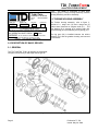
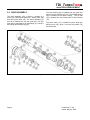
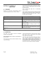
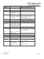
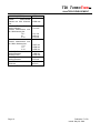
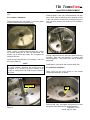
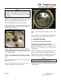
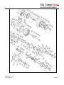
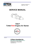
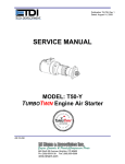
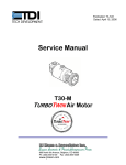
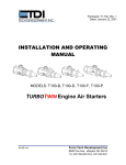
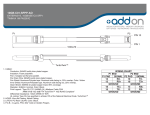
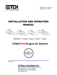
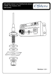
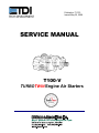
Publication T1-723
Issued May 30, 2008
SERVICE MANUAL
T100-V
TURBOTWIN Engine Air Starters
TDI TURBOTWIN™
FROM TECH DEVELOPMENT
SECTION 1.0 INTRODUCTION
1.1 GENERAL INFORMATION
This manual provides information for servicing,
disassembly, and reassembly of the TDI Turbotwin
T100-V air starters.
If there are questions not
answered by this manual, please contact your local TDI
distributor or dealer for assistance. Illustrations and
exploded views are provided to aid in disassembly and
reassembly.
The TDI Turbotwin T100-V engine starters are specially
designed for starting today’s automated, low-emission
engines. The Turbotwin uses aerodynamic speed
control, eliminating the need for a mechanical
automatic trip valve (ATV) to control starter speed.
The Turbotwin T100-V air starters are suited to operate
within a wide range of inlet pressures and ambient
temperatures.
These starters are designed for
operation with either compressed air or natural gas.
The robust turbine motor design in the Turbotwin T100V starters has no rubbing parts, and is therefore
tolerant of hard and liquid contamination in the supply
gas with almost no adverse affects. The motor is well
adapted to running on “sour” natural gas.
As with all TDI air starter products, there are no rubbing
parts so there is no lubrication required.
This
eliminates failures due to lubricator problems, the
expense of installing and maintaining the system, and
the messy and hazardous oil film around the starter
exhaust. The starter is factory grease packed for the
life of the starter so it requires no maintenance.
NOTE
Throughout this manual, the term “air” is used to
donate the starter drive medium. Unless otherwise
stated, “air” means compressed air or natural gas.
Please review the rest of this manual before attempting
to provide service to the Turbotwin T100-V starters.
1.2 WARNINGS, CAUTIONS, & NOTES
Throughout this manual, certain types of information
will be highlighted for your attention:
WARNING - used where injury to personnel or damage
to equipment is possible.
Publication T1-723
May 30, 2008
CAUTION - used where there is the possibility
of damage to equipment.
NOTE - use to point out special interest
information.
1.3 DESCRIPTION OF OPERATION
The Turbotwin T100-V starters are powered by a pair
of axial flow turbines coupled to a simple planetary
gear reduction set. The T100-V starters incorporate an
inertia bendix drive coupled to the starter gearbox drive
train to provide a means of disengaging the pinion from
the engine’s ring gear.
The high horsepower of the turbine air motor combined
with the spur gear speed reducer results in a very
efficient and compact unit. The Turbotwin T100-V
starters can be used over a wide range of drive
pressures from 40 psig (2.6 BAR) to 150 psig (10 BAR)
and are suitable for operation on air or natural gas.
1.4 INSTALLATION AND SERVICE
It is important to properly install and operate the TDI
Turbotwin T100-V starters to receive the full benefits of
the turbine drive advantages. It must be installed in
accordance with the instructions provided by Tech
Development, Inc. (TDI).
WARNING
Failure to properly install the starter or failure to
operate it according to instructions provided byTDI may
result in damage to the starter or engine, or cause
personal injury. DO NOT OPERATE THIS STARTER UNLESS
IT IS PROPERLY INSTALLED ON AN ENGINE.
Repair technicians or service organizations without
turbine starter experience should not attempt to repair
this starter until they receive factory approved training
from TDI, or its representatives. Proper operation and
repair of your TDI Turbotwin will assure continuous
reliability and superior performance for many years.
1.5 NAMEPLATE INFORMATION
The nameplate located on the turbine housing provides
important information regarding the construction of your
T100-V starters. Refer to Figure 1.
NOTE
You should always have the starter’s Part Number,
Serial Number, Operating Pressure, and Direction of
Rotation information before calling your TDI distributor
or dealer.
Page 1
TDI TURBOTWIN™
FROM TECH DEVELOPMENT
motor.
The starter is composed of three basic
assembly groups: Turbine Housing Assembly; Gearbox
Housing Assembly; and Drive Assembly.
TURBOTWIN™
PNUEMATIC STARTER
TECH
INC.
6800 POE AVE.,DAYTON OH
MODEL NO.
SERIAL NO.
T112V
9911-210
DEVELOPMENT
CW (RH)
(CCW) LH)
X
PART NUMBER
T112-60031-01R-1-03
…
AIR OR NAT. GAS USAGE HOUSING PROOF PRESSURE IS 600 PSIG
MAX OPERATING INLET PRESS. 150
WARNING
PSIG
DO NOT OPERATE UNLOADED, WITHOUT EXHAST
GUARD OR WITHOUT EXHAUST FITTING
Figure 1. TDI Turbotwin Nameplate
2.2 TURBINE HOUSING ASSEMBLY
The Turbine housing assembly, refer to figure 3,
consists of a stage one (16) and a stage two (5)
turbine wheel mounted on sungear shaft (31) . The
front bearing (8) is secured by a retainer plate (30).
The aft bearing (8) is preloaded by a wavy spring (10).
The ring gear (28) is installed between the turbine
assembly (25) and the gearbox housing and secured
by six screws.
2.0 DESCRIPTION OF BASIC GROUPS
2.1 GENERAL
The TDI TurboTwin T100-V air starters are lightweight,
compact units driven by a dual stage turbine type air
Figure 3.
Page 2
Turbine Housing Assembly
Publication T1-723
Issued: May 30, 2008
TDI TURBOTWIN™
FROM TECH DEVELOPMENT
2.3 GEARBOX HOUSING ASSEMBLY
The gearbox housing assembly, refer to figures 4,
consist of a planet gear carrier shaft (33), three planet
gears (35), needle bearings (36), gear spacers (34),
and planet pins (37).
The carrier shaft is mounted on two ball bearings (39)
in the gearbox housing (49). The aft bearing is
preloaded by use of spring washers (40). The forward
bearing is installed into the bearing housing (44), which
is secured by four screws (45) to the gearbox housing.
The spur gear (46) is installed on the carrier shaft and
secured by the bearing locknut (48).
Figure 4. Gearbox Housing Assembly
Publication T1-723
May 30, 2008
Page 3
TDI TURBOTWIN™
FROM TECH DEVELOPMENT
2.4 DRIVE ASSEMBLY
The drive assembly, refer to figure 5, consists of a
piston (54), helical shaft spline (57), dental clutch (59)
and drive pinion shaft (62). The clutch assembly (57
thru 65) is installed into the spur gear (66). The spur
gear (66) is supported by the aft bearing (67), which is
secured by the retaining ring (68).
The roller bearing (69) is installed into spur gear (65)
and secured by retaining ring (70). The forward bearing
(69) is pressed into the drive housing. The lip seal
(76) is pressed into the forward side of drive housing
(73).
The pinion collar (77) is installed on pinion shaft (63)
behind pinion (78), which is secured by washer (79)
and screw (80).
Figure 5. Drive Assembly
Page 4
Publication T1-723
Issued: May 30, 2008
TDI TURBOTWIN™
FROM TECH DEVELOPMENT
SECTION 3.0 DISASSEMBLY
3.1 GENERAL
Always mark adjacent parts on the starter housing;
Nozzle 2/ Containment Ring (12), Turbine Housing
(25), Gearbox Housing (49), and Drive Housing (73) so
these parts can be located in the same relative position
when the starter is reassembled.
Do not disassemble the starter any further than
necessary to replace a worn or damaged part
Always have a complete set of seals and o-rings on
hand before starting any overall of a Turbotwin T100-V
starter. Never use old seals or o-rings.
The tools listed in Table 1 are suggested for use by
technicians servicing the T100-V Turbotwin starters.
The best results can be expected when these tools are
used, however the use of other tools are acceptable.
Contact TDI for a list of additional tools that maybe
required when overhauling T100-V air starters.
TOOL DESCRIPTION
TDI/PN
Spanner wrench
52-20134
Spanner wrench
52-21345
Shaft Removal Tool
2-26945
Stage 2 Rotor Puller Tool
52-20076
Carrier Shaft Holding Tool
52-20202
Tool, Bearing Pressing
52-20143
Tool, Bearing/Seal
2-26943
Table 1. T100-V Service Tools
(80) counterclockwise to remove using a 3/4" socket
and wrench.
NOTE
Use only a soft tooth vise to secure the pinion to avoid
damaging pinion.
This screw is torqued to 100 lb ft during assembly
therefore a large wrench may be required when
removing screw.
Remove washer (79), pinion (78) and spacer (77) from
pinion shaft (62). If pinion is too tight, place a
screwdriver underneath pinion and lift up on pinion to
remove from shaft.
Remove helical spline shaft assembly (55-64) from
spur gear shaft (66). Remove spring (65) from shaft.
Use press tool and arbor press to remove spur gear
shaft (66) from drive housing (73).
Use a screwdriver to remove lip seal (76) from forward
end of drive housing (73).
Use press tool and arbor press to remove spur gear
shaft (66) from drive housing (73).
3.2 DRIVE HOUSING
3.2.1 Removal of Drive Housing
Mark position of drive assembly (73) relative to gearbox
housing (49) for reference during reassembly.
Remove the eight screws (74) and pull drive assembly
from gearbox housing. If drive housing is too tight, tap
it with a mallet to loosen.
Remove o-ring (72) from aft end of drive housing(73).
3.2.2 Pre-engaged Drive Disassembly
Secure pinion (78) in a soft tooth vise while supporting
aft end of the T100-V air starter. Rotate pinion screw
Publication T1-723
May 30, 2008
Remove retainer ring (71) and bearing (70) from
forward end of spur gear shaft (66).
Page 5
TDI TURBOTWIN™
FROM TECH DEVELOPMENT
Remove retainer ring (68) and press bearing (67) from
spur gear shaft (66) as shown.
Remove retainer ring (55) and bearing (56) from helical
spline shaft (57).
Remove bearing from drive housing using bearing
puller and pressing as shown.
3.3 GEARBOX HOUSING
3.3.1 Removal of Gearbox Housing
Remove the screws (50) securing the gearbox (49) to
the turbine assembly (25).
Remove ring gear (28) from turbine (25) or gearbox
assembly (49). The ring gear could remain on either
assembly when separation occurs.
3.3.2 Gearbox Disassembly
Place gearbox assembly (49) on flat surface with aft
end facing up.
Remove four screws (45) and lift carrier shaft assembly
(33) from gearbox housing.
Page 6
Publication T1-723
Issued: May 30, 2008
TDI TURBOTWIN™
FROM TECH DEVELOPMENT
Place carrier shaft assembly on carrier shaft holding
tool (52-20202) and use a screwdriver to remove tang
of lock washer (47) from slot of retainer nut (48).
Place TDI tool P/N 52-20134 (Spanner Wrench) over
shaft and into slots of retainer nut (48). Hold carrier
shaft assembly down and turn spanner wrench CCW to
remove retainer nut, lock washer (47), spur gear (46),
and woodruff key (38) from carrier shaft (33).
Use an arbor press to remove carrier shaft (33) from
bearing housing (44). The bearing housing must be
elevated and supported to remove carrier shaft.
Remove four screws (18) and bearing retainer plate
(30) from turbine housing.
Using the shaft removal tool P/N 2-26945, press on the
aft end of the turbine shaft (31) while supporting the
turbine housing (25).
Press the turbine shaft (31) through the aft bearing (8)
until the shaft is completely out of the housing (25).
Remove the woodruff key (17), seal spacer (14),
bearing spacer (29), and bearing (8) from turbine shaft
NOTE
Do not support the bearing housing on the four lips as
they could break while pressing on carrier shaft.
Remove spring washers (40), spring retaining plates
(41), and bearing spacer (43) from carrier shaft.
Remove aft bearing (39) from shaft by pressing shaft
while supporting bearing.
3.3.3 Planet Gear Disassembly
Remove retainer ring (32) from planet shaft (37) and
push planet shaft through assembly.
Slide the planet gear (35) from carrier shaft and
remove two spacers (34).
Use press tool to remove needle bearing (36) from
planet gear (35).
3.4 TURBINE HOUSING
(31). The forward bearing can be removed from the
shaft by pressing the shaft through the bearing while
supporting bearing.
Separate the stage 2 nozzle assembly (12) from the
turbine assembly (25) by firmly holding the turbine
assembly, while tapping nozzle 2 with a mallet. If
nozzle 2 is too tight, it can be removed by installing two
threaded screws into nozzle 2 and using them as jacks
to separate nozzle 2 from the turbine assembly.
NOTE
Rotate the stage 1 rotor if necessary to allow the jacks
to travel through the large holes in the rotor. The jacks
will damage the stage 1 rotor if pressure is applied to
the rotor while removing nozzle 2.
3.4.1 Stage 2 Rotor Removal
Place the turbine assembly (25) with ring gear (28) on
a flat surface with (exhaust) end up and remove the six
screws (1), and the screen (2).
Secure the stage 2 rotor (5) and remove the turbine
screw (3) and washer (4).
Install the rotor puller tool P/N 52-20076 and remove
the stage 2 rotor.
Remove woodruff key (6) from the turbine shaft (31).
3.4.2 Turbine Shaft Removal
Place the turbine housing on a flat surface with the sun
gear end facing up.
Publication T1-723
May 30, 2008
Remove stage 1 rotor (16) and o-ring (12) from nozzle
2.
Remove the four screws (18) and nozzle 1 (19) from
the turbine assembly.
Remove o-ring (21) from aft end of turbine housing.
Remove the seal spacer (14) from the forward side of
nozzle 2 (12). Place the stage 2 nozzle on the exhaust
end. Press through the forward lip seal onto the
bearing (8) until it, including the aft lip seal and seal
spacer disengages from the nozzle. Turn the nozzle
over and press on the forward lip seal to remove.
Page 7
TDI TURBOTWIN™
FROM TECH DEVELOPMENT
SECTION 4.0 CLEANING and
INSPECTION
Clean aluminum parts using the solutions per Table 2;
soak for 5 minutes. Remove parts, rinse in hot water,
and dry thoroughly.
4.1 CLEANING
Clean corroded steel parts with a commercially
approved stripper.
Degrease all metal parts, except bearings, using a
commercially approved solvent. Refer to Table 2.
Clean corroded aluminum parts by cleaning as stated
above and then immerse the parts in chromic-nitricphosphoric acid pickle solution per Table 2. Rinse in
hot water and dry thoroughly.
MATERIAL or COMPOUND
Degreasing Solvent
Acetone
Aluminum Cleaning Solution
MANUFACTURER
Commercially Available
Commercially Available
Diversey Corp., 212 W. Monroe, Chicago, IL 60606
Dissolve 5 oz of Diversey 808 per gallon of water at
155°- 165°F.
Steel Cleaner - Rust & Corrosion
Oakite Products Corp., 50 Valley Rd., Berkeley
Heights, NJ 07992
Mix 3-5 lb. of Oakite rust Stripper per gallon of water;
use at 160°- 180°F.
Chromic-Nitric-Phosphoric Acid Pickle Solution
Mix 8lb. of chromic acid, 1.9 gal. of phosphoric acid,
1.5 gal. of nitric acid with enough water to make a
total of 10 gal. of solution.
WARNING Follow all instructions provided with the MSDS sheets on the materials and compounds listed
above.
Table 2. Cleaning Materials and Compounds
4.2 INSPECTION
Use Table 3 as a guide to check for acceptable
condition of the parts listed.
Check all threaded parts for galled, crossed stripped, or
broken threads.
Check all parts for cracks, corrosion, distortion, scoring,
or general damage.
Page 8
Check all bearing bores for wear and scoring. Bearing
bores shall be free of scoring lines, not to exceed
0.005″ width and 0.005″ depth.
Check gear teeth and turbine housing ring gear for
wear. In general, visually check for spalling, fretting,
surface flaking, chipping, splitting, and corrosion. If
wear is apparent, check the gear teeth dimensions in
accordance with Table 4. Nicks and dents that cannot
be felt with a .020 inch radius scribe are acceptable.
Publication T1-723
Issued: May 30, 2008
TDI TURBOTWIN™
FROM TECH DEVELOPMENT
Part
Description
Pinion
Drive Housing
Planet Gear
Check For
Chipped Teeth, Cracks
Cracks and breakage
Cracked, chipped, or galled
teeth. Wear must not exceed
limits per Table 4.
Carrier Shaft
Cracks, scoring or raised
metal in planet shaft holes
and keyways.
Integrity of
knurl connection.
Planet Pins
Wear grooves or flat spots
Washers
Gearbox Housing
Sungear
/
Turbine Shaft
Wear created grooves
Cracks and Breakage
Cracks, scoring, wear created
grooves, chipped or broken
gear- teeth, galling or scoring
on bearing surface of shaft.
Raised metal on the keyway.
Parallelism of end surfaces
Cracks and breakage
Spacers
Turbine Housing
Ring Gear
Seal Assembly
Seal Spacer
Needle Bearings
Ball bearings
Containment
Ring/ Nozzle
Turbine Rotors
Cracks, wear, chipped, or
broken gear teeth.
Wear grooves or scratched
surfaces on carbon ring.
Wear Grooves
Freedom of needle rollers
Freedom of rotation without
excessive play between races
Corrosion, erosion, cracks
and broken nozzle edges.
Corrosion, erosion,
and broken edges.
cracks
Requirements
(Defective Parts Must Be Replaced)
Defective unit to be replaced. Use figure 5
as a guideline for acceptable pinion wear.
Cracks are not acceptable
Wear must not exceed limits per table 4.
There shall be no evidence of excessive
wear.
Deformation of metal smearing in planet
pin holes & keyways not acceptable.
Scoring on bearing diameter not to
exceed .005″ depth.
Wear must not exceed limits per Table 4.
Wear grooves in flat spots not permitted.
Wear must not exceed limits per Table 4.
Wear must not exceed limits per Table 4.
Cracks and breakage not acceptable.
Wear must not exceed limits per Table 4.
Ends must be parallel within 0.0005″.
Cracks and breakage are not acceptable.
Minor surface damage is permitted if
function is not impaired.
Wear must not exceed limits per Table 4.
Wear is not permitted.
No wear permitted.
Replace bearings
Replace bearings
Cracks and breakage are not acceptable.
Minor surface damage is permitted if
function is not impaired.
Minor tip rub is permitted if function is not
impaired.
Tip wear; bore and key way Wear is not permitted.
wear
Table 3. Parts Inspection Check Requirements
Publication T1-723
May 30, 2008
Page 9
TDI TURBOTWIN™
FROM TECH DEVELOPMENT
PART DESCRIPTION
LIMIT, Inches
Ring gear / Turbine Housing
Internal
measurement
between two .084″ diameter 5.0890 max.
pins.
Sun Gear / Turbine Shaft
0.6690 min
Bearing diameter
External measurement over
two .096 diameter pins.
7.5:1
0.952 min
9:1
0.808 min
11.4:1
0.670 min
Planet Gear
External measurement over
two .0864″ diameter pins.
2.3067 min
7.5:1
2.3699 min
9:1
2.4359 min
11.4:1
Carrier Shaft
1.1800 min
Bearing Diameter
0.8750 max
Planet Pin Bore
Planet Pins
0.873 min
Bearing Diameter
Thrust Washer
.055 min
Thickness
Table 4. Parts Wear Limits
Page 10
Publication T1-723
Issued: May 30, 2008
TDI TURBOTWIN™
FROM TECH DEVELOPMENT
SECTION 5.0 ASSEMBLY
5.1 GENERAL
The tools listed in Table 1 are suggested for use by
technicians servicing the T100-V starters. The best
results can be expected when the proper tools are
used, however, use of other tools is acceptable.
CAUTION
Replace all screws , O-rings, lip seals, and bearings
when the T100-V starter is reassembled. These parts
are included in the overhaul kit shown in Section 6.0
NOTE
Always press the inner race of a ball bearing when
installing a bearing on a shaft. Always press the outer
race of a ball bearing when installing into a housing.
Refer to Section 6.0, for a list of kits and components,
which are available to aid in rebuilding T100-V starters.
Press the bearing/shaft assembly (8, 31), keyway end
first, into bearing housing of the turbine housing (25).
Use press tool P/N 2-26943 if required. Do not press
on the end of the shaft because the load could damage
the balls of the bearing.
Install bearing retainer plate (30) and secure with four
screws (18). Torque screws to 81 in-lbs.
Lubricate all O-rings with petroleum jelly or Parker-ORing Lube before assembly. Refer to Table 5 for a list
of materials to be use during assembly.
MATERIALS
SOURCE
Petroleum Jelly
Commercially Available
Parker-O-Ring Lube
Commercially Available
Loctite RC290
Commercially Available
Grease, gearbox
TDI P/N 9-94121-001
Table 5. Materials for Assembly
CAUTION
The screws that secure the Containment Ring/ Stage 2
Nozzle must have a drop of Loctite RC290 applied to
the threads before being used.
Place turbine housing with sun gear end down on a flat
surface, while using ring gear to support turbine
housing. Install long bearing space (29) and seal
spacer (14) over shaft.
5.2 TURBINE HOUSING
5.2.1 Turbine Shaft Installation
O-ring
Press the bearing (8) onto the shaft (31) until seated.
Support the shaft and press on the inner race only with
press tool P/N 2-26943.
Publication T1-723
May 30, 2008
Page 11
TDI TURBOTWIN™
FROM TECH DEVELOPMENT
Install o-ring (21) into the aft face of the turbine housing
(25).
5.2.2 Nozzle 1 Installation
Press the lip seal (15) into nozzle 1 (19) using press
tool P/N 2-26943 with the lips facing up.
Install nozzle 1 onto the turbine housing (25). Orient
the nozzles facing the air inlet (23) and install four
screws (18) to secure the nozzle. Do not tighten the
screws at this time.
Install the large woodruff key (17) for stage 1 rotor into
the turbine shaft (31).
NOTE
The rotation of the turbine assembly is opposite from
the pinion rotation, therefore this nozzle must be
configured for LH (CCW) if the pinion rotation is RH
(CCW), or configured for RH (CW) if pinion rotation is
LH (CCW).
5.2.3 Rotor 1 Installation
Install the stage 1 rotor (16), while supporting sun gear
end of shaft, onto the turbine shaft by aligning the slot
in the rotor with the woodruff key and hand press the
rotor until firmly seated. Use press tool P/N 2-26943 if
required.
Visually inspect that the key was not pushed out during
assembly. Note that the direction of rotation was
oriented properly. This turbine rotor can be installed
backwards.
Install spacer (14) onto aft end of turbine shaft (30).
5.2.4 Nozzle 2 Installation
Place o-ring into the inner groove of the nozzle/
containment assembly, as shown.
Woodruff key
o-ring
Page 12
Place lip seal onto seal spacer and press the lip seal
and spacer into forward end of nozzle assembly.
Publication T1-723
Issued: May 30, 2008
TDI TURBOTWIN™
FROM TECH DEVELOPMENT
Place the completed nozzle assembly onto the
completed turbine housing with the dowel pin on the
same side as the inlet. Press down on the nozzle
assembly until it is completely seated, making sure to
line up the holes.
Dowel pin
Place an o-ring into the groove on the nozzle
assembly, as shown.
Place the turbine assembly onto the arbor press and
place a bearing (8) onto the turbine shaft. Using the
press and tool 2-26943, press the bearing into the
nozzle assembly.
o-ring
Place a wave spring washer (10) into the nozzle
assembly so that it rests on the lip seal.
Wave spring
Rotate the turbine shaft so that two of the four holes in
the nozzle assembly are lined up with holes in the
rotor. The four holes are used to access and tighten
the screws securing nozzle 1. Torque screws to 81 in.lbs.
Rotate the turbine shaft again so that the other two
holes in the nozzle assembly are lined up with holes in
the rotor. Again, torque the turbine housing screws to
81 in.-lbs.
Publication T1-723
May 30, 2008
Page 13
TDI TURBOTWIN™
FROM TECH DEVELOPMENT
NOTE
The rotation of the turbine assembly is opposite from
the pinion rotation, therefore this nozzle must be
configured for LH (CCW) rotation if the pinion rotation
is RH (CW), or configured for RH (CW) if pinion rotation
is LH (CCW).
Apply Loc-tite 242 and to the threads and install four
screws (11). Hand-thread the screws into the nozzle
assembly. Torque the four screws to 100 in.-lbs.
Place a bearing spacer (7) over the turbine shaft.
Insert a woodruff key (6) into the upper slot on the
turbine shaft, as shown. Use the pliers to squeeze the
woodruff key into the shaft.
5.2.5 Air Inlet Installation
Woodruff key
Place
(23).
the O-ring (24) into the groove on the air inlet
Install the 2″ NPT air inlet flange (23) and secure with
six screws (22). Tighten the six screws to 385 in-lb.
5.3 GEARBOX HOUSING
5.3.1 Planetary Gear Carrier Reassembly
Place a turbine rotor (5) over the turbine shaft, as
shown. Make sure the notch in the turbine rotor is lined
up with the woodruff key. Press down on the rotor until
it is completely seated.
Obtain a rotor retention screw (3) and place a washer
(4) on it. and hand-thread the screw into the turbine
shaft.
Press needle bearing (36) into planet gears (35). The
planet gears are not identified by part number,
therefore, dimensionally check if correct gears are
being used.
Use table 4 for over the wire
measurements.
With a thrust washer (34) on each side of gear, slide
gear into carrier slots (33), and align with pin holes.
Lightly slide plant shafts into aligned holes, making
sure retainer ring groove on end of pins goes in first.
Using the torque wrench, torque the rotor retention
screw to 220 in.-lbs.
NOTE
Make sure that anti-rotation pins on shafts are properly
located in retaining slots of carrier shaft (32).
Install the exhaust screen (2) and secure with six
screws (1). Tighten the screws to 113 in-lb.
Install retainer ring (32) onto planet shaft (37) using a
retainer ring tool.
Page 14
Publication T1-723
Issued: May 30, 2008
TDI TURBOTWIN™
FROM TECH DEVELOPMENT
Retainer ring
5.3.2 Gearbox Reassembly
Install bearing (39) into the bearing housing (44) and
secure with retaining ring (42).
Place O-ring (13) onto outer diameter of gearbox
housing (49).
Apply grease to spur gear as shown.
Press aft bearing (39) onto carrier shaft (33) using TDI
Tool P/N 52-20143. Pressing force should be on the
inner race of bearing.
Install carrier shaft assembly into aft side of gearbox
housing (49) and secure with four screws (45) as
shown above. Torque to 113 in-lbs.
Install 4 spring washers (40), spring retaining plate (41)
and bearing spacer (43) onto shaft and locate against
bearing as shown above.
Position bearing housing assembly (39,42,44) over
carrier shaft (33) and press until firmly seated as shown
above.
Install woodruff key (38) into slot on carrier shaft (33)
and install spur gear (46) on carrier shaft aligning slot
on gear with woodruff key.
Apply lubrication to o-ring and piston and install o-ring
(53) onto piston (54).
Install piston into forward side of gearbox housing (49).
Piston
Place bearing housing assembly on carrier shaft
holding tool P/N 2-20202. Install lockwasher (47) and
retainer nut (48). Torque to 90-100 ft.lb. Tang lock
washer into retainer nut slot.
Publication T1-723
May 30, 2008
Page 15
TDI TURBOTWIN™
FROM TECH DEVELOPMENT
5.4 DRIVE HOUSING
5.4.1
Drive Reassembly
Install bearing (70) into forward end of spur gear shaft
(66) and secure with retaining ring (71).
Press bearing (67) onto spur gear shaft (66) and
secure with retaining ring (68).
Press bearing (69) into drive housing (73) until seated
firmly into housing.
Install spacer (63), spring (65), and pinion spacer (77)
onto pinion drive shaft assembly and install into aft end
of spur gear (66). The gears on helical shaft (57) must
be aligned into the aft end of the spur gear shaft (66).
Press the helical shaft assembly into the spur gear
shaft until end of shaft protrudes from forward end of
drive housing.
Maintain pressing force and install pinion onto drive
shaft (62). Secure with screw (80). Torque to 100 ft.
lb.
Press lip seal (76) into forward end of drive housing
(73) and install O-ring (72) into O-ring groove on drive
housing.
5.5 FINAL ASSEMBLY
Install spur gear assembly (66-71) into drive housing
(73) until firmly seated.
Thoroughly grease planet gears (35), ring gear (28),
sun gear (31), spur gears using TDI grease P/N: 994121.
Install bearing (56) onto aft end of drive shaft assembly
(57-62) and secure with retaining ring (55).
Place turbine assembly with aft end on a flat surface
and install ring gear (28).
Rotate carrier shaft (33) slightly, and at the same time,
align gearbox into the front of turbine housing (25).
Install six gearbox to turbine assembly screws (50) and
torque 113 in-lbs.
Install drive assembly (73) onto gearbox assembly (49)
and secure with eight screws (74). Torque to 113 in.
lbs.
Retainer ring
Lubricate inner diameter of spur gear assembly (66)
using TDI grease P/N: 9-94121.
Page 16
Publication T1-723
Issued: May 30, 2008
TDI TURBOTWIN™
FROM TECH DEVELOPMENT
SECTION 6.0 PARTS LIST
ILLUSTRATED PARTS LIST FOR MODEL T100-V SERIIES AIR STARTERS
KEY NO.
DESCRIPTION
PART NUMBER
OVERHAUL KIT
P/N: T10V-28574
x
1
Screw (6)
11F- 25020-064
2
Exhaust Guard
2-28175
3
Screw
14F- 25028-012
4
Washer
9-93047
5
Rotor 2 (See Note)
2-26604
6
Woodruff Key
9-90211-006
7
Bearing Spacer
9-93091-005
8
Bearing (2)
9-91224
9
O-ring
9-90001-027
10
Wave Spring Washer
9-90439
11
Screw (4)
11A-37516-008
12
Nozzle 2, R.H. (See Note)
2-27825-00R
12
Nozzle 2, L.H. (See Note)
2-27825-00L
13
O-ring (2)
9-90001-050
14
Seal Spacer (2)
9-93083-001
15
Lip Seal (2)
2-26719
16
Rotor 1 (See Note)
2-26603
17
Woodruff Key
9-90211-009
18
Screw (8)
14F-19024-008
19
Nozzle 1, R.H., 9 Nozzles (See Note)
2-26718-09R
19
Nozzle 1, L.H., 9 Nozzles (See Note)
2-26718-09L
19
Nozzle 1, R.H., 12 Nozzles (See Note)
2-26718-12R
19
Nozzle 1, L.H., 12 Nozzles (See Note)
2-26718-12L
19
Nozzle 1, R.H., 15 Nozzles (See Note)
2-26718-15R
19
Nozzle 1, L.H., 15 Nozzles (See Note)
2-26718-15L
Publication T1-723
May 30, 2008
x
x
x
x
x
x
x
x
x
Page 17
TDI TURBOTWIN™
FROM TECH DEVELOPMENT
KEY
NO.
DESCRIPTION
PART NUMBER
OVERHAUL KIT
P/N: T10V-28574
19
Nozzle 1, R.H., 21 Nozzles (See Note)
2-26718-21R
19
Nozzle 1, L.H., 21 Nozzles (See Note)
2-26718-21L
20
Pipe Plug
9-93556-004
21
O-ring
9-90001-034
x
22
Screw (6)
14F-31218-016
x
23
Inlet Flange
1-18967
24
O-ring
9-90001-037
25
Turbine Housing
2-27869
26
Pipe Plug
9-93501-004
27
O-Ring
9-90001-050
28
Ring Gear
2-27870
29
Bearing Spacer
9-93091-001
30
Clamping Plate
2-26750
31
Turbine Shaft (7.5:1)
2-26554
31
Turbine Shaft (9.0:1)
2-27238
31
Turbine Shaft (11.4:1)
2-28710
32
Retainer Ring (3)
9-92001-001
33
Carrier Shaft (7.5:1)
2-27798-002
33
Carrier Shaft (9.0:1)
2-27798-001
33
Carrier Shaft (11.4:1)
2-27798-003
34
Spacer, Gear (6)
9-93004
35
Planet Gear (3) (7.5:1)
1-19441
35
Planet Gear (3) (9.0:1)
1-18779
35
Planet Gear (3) (11.4:1)
1-19440
36
Needle Bearing (3)
9-91004-001
37
Planet Shaft (3)
2P-20182
Page 18
x
x
x
Publication T1-723
Issued: May 30, 2008
TDI TURBOTWIN™
FROM TECH DEVELOPMENT
KEY
NO.
DESCRIPTION
PART NUMBER
OVERHAUL KIT
P/N: T10V-28574
38
Woodruff Key
9-90227-025
39
Bearing (2)
9-91351
40
Wave Spring Washer
9-90402-025
41
Spring Retaining Plate
2-27731
42
Retaining Ring
9-92001-033
43
Bearing Spacer
9-93007-003
44
Housing, Bearing
2-27726
45
Screw (4)
14F-25020-012
46
Gear, Spur
2-27712
47
Lockwasher, Bearing
9-93061-007
48
Locknut, Bearing
9-92127-007
49
Housing, Gearbox
2-27728
50
Screw (6)
71F-25020-36
51
Fitting, Filter
2-28270
52
Plug, Pipe (2)
9-93556-004
53
O-Ring, Piston
9-90001-327
54
Piston
2-27921
55
Retainer Ring
9-92001-041
56
Bearing
9-91254
57
Spline, Helical Shaft, R.H. (See Note
1)
2-27977-00R
57
Spline, Helical Shaft, L.H. (See Note
1)
2-27977-00L
58
Spring, Compression
9-90444
59
Clutch, Helical, R.H.
2-27713
59
Clutch, Helical, L.H.
2-27716
60
Ring, Retainer
9-92001-037
61
Bearing, Needle Roller
9-91409
Publication T1-723
May 30, 2008
x
x
x
x
x
Page 19
TDI TURBOTWIN™
FROM TECH DEVELOPMENT
KEY
NO.
DESCRIPTION
PART NUMBER
OVERHAUL KIT
P/N: T10V-28574
62
Shaft, Drive Pinion R.H.
2-28169-001
62
Shaft, Drive Pinion L.H.
2-28169-002
63
Washer, Thrust (2)
9-93120
x
64
Ring, Retainer
2-28051
x
65
Spring, Compression
9-90447
66
Gearshaft, Spur
2-27711
67
68
Bearing, Ball
Ring, Retaining
9-91431
9-92001-036
x
69
Bearing, Ball
9-91434
x
70
Bearing, Needle Roller
9-91435
x
71
Ring, Retainer
9-92001-042
72
O-Ring
9-90001-158
73
Housing, SAE
2-27729
74
Screw (8)
71F-25020-016
75
Fitting, Vent
9-93662-012
76
Seal, Lip
2-22084
77
Spacer, Pinion
2-28178
78
Pinion, 6/8P, 12T, Bi-directional
2-28167
78
Pinion, 6/8P, 15T, Bi-directional
2-28568
78
Pinion, 3.5 MOD, 15T, Bi-directional
2-28242
78
Pinion, 3.5 MOD, 17T, Bi-directional
2-28632
79
Washer, Pinion
9-93124
x
80
Screw
71F-50020-016
x
x
x
x
Note: The rotation of the turbine assembly is opposite from the pinion rotation,
therefore the rotors and nozzles must be configured for LH (CCW) rotation if the pinion rotation is
RH (CW), or configured for RH (CW) if pinion rotation is LH (CCW).
Page 20
Publication T1-723
Issued: May 30, 2008
TDI TURBOTWIN™
FROM TECH DEVELOPMENT
Publication T1-723
May 30, 2008
Page 21