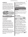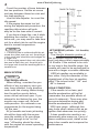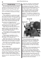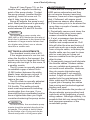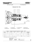
1
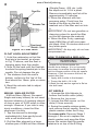
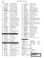
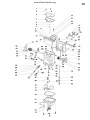
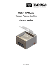
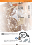
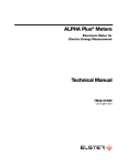
www.ClassicCycles.org
HSR
Tuning Manual
Revised 02/10/03
2
www.ClassicCycles.org
Tuning the HSR42/45/48
Carburetors
Your Mikuni HSR comes from
the factory with the tuning parts we
found to work with the great majority
of engine performance modifications.
However, the large number of
differing after market exhaust and air
cleaner systems makes it virtually
impossible to accommodate all
possible combinations with one
carburetor set-up.
Your HSR will almost certainly
run correctly on your engine with
the installed parts. But, if it doesn’t,
you may alter its tuning to suit your
engine’s needs by following this
guide.
Some exhaust system designs
strongly interfere with carburetor
tuning. For instance, it is very difficult
to get smooth and responsive
carburetion through the entire rpm
range with open straight pipes and
other unbaffled exhausts. In addition,
very small volume, small diameter
mufflers are often ‘seen’ by the
engine as straight pipes and present
similar tuning difficulties.
Very long duration cams often
cause relatively poor running
below 3,000 rpm, depending upon
the individual cam’s intake valve
closing point. Such cams cause
reverse airflow out the mouth of the
carburetor (often called “reversion” or
“stand-off”) that can be mistaken for
a carburetor tuning problem.
If you have any doubts about
a particular exhaust system,
air cleaner or ignition, you may
substitute the Harley Screamin’
Eagle parts as a “reality check.”
When re-tuning is required, it
usually involves small alterations
to the idle and/or main system. The
following pages supply enough
information to make such alterations
relatively simple.
Please note that there is no point
in attempting to tune any carburetor
unless the engine is sound and in a
good state of tune. If you have any
doubts about the general condition of
your engine, have it checked by your
dealer or an experienced mechanic
before attempting to fine-tune your
Mikuni.
AIR LEAKS:
We have found that Harley-pattern
engines tend to develop minor air
leaks between the manifold and
heads. These leaks affect air/fuel
mixtures at low throttle settings and
can be troublesome at idle. For best
performance, it is important that you
test for and eliminate any such leaks.
The test is simple : With the engine
warm and idling, spray WD-40 or
similar paint-safe liquid around the
junctions of the manifold, carb and
heads. If the engine changes from
its steady idle, if it surges or misses,
then there is an air leak that should
be corrected. Be sure to keep the
spray away from the air cleaner to
avoid a false indication.
www.ClassicCycles.org
NOTE:
For a quick and accurate analysis,
when fine-tuning your HSR, we recommend using “witness” marks on the
throttle grip and throttle housing. Use
masking tape on the grip and an indicator mark on the throttle housing. Mark the
tape in 1⁄4 throttle increments from idle
to full throttle. You can then accurately
identify the throttle opening and adjust
the proper tuning components.
Figure: T1
HSR TUNING SYSTEMS:
The HSR carburetor is divided into
four interdependent systems:
1. Choke system
2. Idle system
3. Main system
4. Accelerator pump system
Each of these systems has
its major effects in a different
throttle range. While there may be
some overlap, each system can
generally be treated as though it is
completely responsible for air/fuel
mixtures within its range of throttle
settings. Three of the systems have
replaceable components that allow
fine-tuning should the need arise.
CHOKE SYSTEM:
The choke system’s purpose is to
provide the rich air/fuel mixture an
engine needs to start and run reliably
when cold. There are no replaceable
tuning parts in the HSR choke
mechanism.
3
The choke is designed to work
correctly with the throttle closed.
Opening the throttle greatly reduces
the action of the choke.
NOTE:
Make sure that the stock HarleyDavidson choke cable is fully seated in
the metal elbow at the carburetor end
of the cable assembly (see Installation
Instructions). Harley ‘s cable is stiff and
can fail to fully seat in the elbow. This
condition results in poor mileage and a
poor idle.
The Mikuni choke cable is more flexible
and less likely to jam. Still, it is best to
check to be sure the cable is installed
correctly.
IDLE SYSTEM:
(Idle - 1/8 throttle)
The HSR idle system has two
tunable components: the Pilot Air
Screw and the Pilot Jet. The air
screw’s purpose is to fine-tune the
mixture at idle. The pilot jet controls
the total amount of fuel passing
through the idle system. The pilot
jet can be exchanged for a richer or
leaner one if needed (see the note
on the following page).
The pilot air screw is set at two
turns open from the factory. This is
the position we have found to be
correct most of the time. If the screw
position has been altered, gently
bottom it and re-open it two full turns.
Next, run the engine until it
reaches normal running temperature.
With the engine idling smoothly,
adjust the pilot air screw in slowly
until the idle either slows or becomes
irregular, then turn the screw out until
the engine again slows or begins to
idle irregularly.
www.ClassicCycles.org
4
Count the number of turns between
the two positions. Set the air screw
mid-way between these too-rich and
too-lean positions.
Use the Idle Adjuster to re-set the
idle speed.
If the engine becomes too hot
during the adjustment procedure, the
resulting idle mixture will prob
ably be on the lean side of correct.
If you have a large fan, use it while
adjusting the mixture. If you do not
have one, you may need to take time
out for a short ride to cool the engine
back to normal temperature.
NOTE:
1. If the best idle is achieved with the air
screw less than one turn out, the pilot jet
is too small and should be exchanged for
a larger one.
2. If the engine speed does not slow after
two-and-a-half turns out, the pilot jet is
too large and should be exchanged for a
smaller one.
MAIN SYSTEM
NOTE:
Cam design effects
When testing, consider the rpm
effects of any accessory cam you
may have installed. Long duration
cams with late closing intake timing
tend to perform poorly below
some critical minimum rpm. If you
attempt to test below this rpm, the
engine may seem soft, flat and
unresponsive. No carburetor can
compensate for the engine being
“off the cam.”
All jet needle and main jet testing
should be done with the engine
near the middle of its rpm range,
but high enough to be “on the
cam.” All testing should be done
with the engine at normal operating
temperature.
Figure: T2
JET NEEDLE (off-idle - 1/4 throttle)
(see Fig. T2)
The straight diameter portion of
the jet needle controls the mixture
from just above idle to approximately
1/4 throttle. If the mixture is too rich
or too lean in this throttle range, the
needle will need to be exchanged for
one with a larger or smaller diameter.
HSR jet needles are available in
four sizes. Only the diameter of the
straight part of the four jet needles
differ. The richest is the “-95” and
“-98” is leanest.
LEAN CONDITION:
If the needle is too lean, part
throttle acceleration will be flat
(remember the possible effects of
cams & exhausts). There may also
be some detonation during part
throttle acceleration in the 2500
- 3000 rpm range, (although this
may have other causes such as an
ignition that advances too quickly).
A lean needle also results in an
abnormally slow warm-up. If any of
these conditions exist, install a one
size richer needle and compare the
performance.
www.ClassicCycles.org
RICH CONDITION:
While a black, sooty spark plug is
a sure sign of richness, others are
more subtle. If your engine responds
crisply at low throttle openings when
cold, chances are the needle is one
size smaller (richer) than it needs to
be. This assumes, of course, that the
idle mixture is correctly tuned.
Poor fuel mileage is another sign of
an over-rich condition. Fuel mileage
is usually measured at cruising
speeds (65 mph on a flat, windless
road) where the jet needle is the
main mixture control.
Poor milege at these speeds can
be corrected by fitting a leaner jet
needle. Raising or lowering the jet
needle has no effect on fuel mileage
below about 70 mph.
JET NEEDLE (1/4 - 3/4 THROTTLE)
The tapered portion of the jet
needle rises out of the needle jet at
about 1/4 throttle. From that point
until the main jet takes over near 3/4
throttle, the jet needle taper is the
main control of mixture strength.
LEAN CONDITION:
If acceleration seems soft or flat
and the engine is slow to respond
when the throttle is quickly opened
from the 1/2 throttle position, the
mixture is too lean. Raise the needle
one notch and repeat the test.
RICH CONDITION:
If acceleration is crisp but the
engine hesitates or staggers as the
throttle is quickly closed from 3/4 to
1/2 throttle, the mixture is too rich.
Lower the needle one notch and
repeat the test. The needle will be
correct when acceleration is crisp at
mid-rpm yet the engine does not load
up during throttle shut down.
5
NOTE:
See the “How To” section at the back
of this manual for jet needle adjustment
and removal procedures.
Figure: T3
MAIN JET SELECTION: 3/4 - full
throttle
DYNAMOMETER METHOD:
Dynamometer testing is a quick
and safe way to determine the correct main jet size. The main jet that
delivers the most power is the best
one. If two jets produce the same
power, use the smaller jet.
One possible issue with dyno testing is temperature. Most dynamometers do not have enough cooling
capacity to allow endless engine
runs without overheating. An overheated engine leads to an incorrect
main jet selection. However, skilled
operators can get the main jet sized
properly with only few runs and temperature should not be a common
problem.
www.ClassicCycles.org
6
WARNING
The following tuning methods require
riding the motorcycle on the open road
and the use of full throttle. This can be
dangerous and, if you choose to use
either to these techniques, be aware of
your surroundings and personal safety.
Roll-off Method:
This method is a good way to get
the main jet either correct or within
one size of correct. It is based on the
fact that that as the throttle is closed,
the air/fuel mixture richens momentarily. This normal enrichening can
be used as a diagnostic tool.
The test is started with the engine
running at an rpm high enough to
ensure that it is “on the cam.”
Open the throttle fully and let the
engine pull for several seconds.
Then, quickly close the throttle to
about the 7/8ths position.
If the engine seems to gain power,
the main jet is too small (lean). Fit a
larger jet.
If the engine hesitates as the
throttle is rolled off, the main jet is
too large. Fit a smaller one.
When the main jet is correct, the
engine will continue to run smoothly
and evenly as the throttle is closed.
Note that a main jet that is far too
rich or lean may cause the engine to
misfire at full throttle.
Roll-on Method:
This is the method used by tuners
at race tracks and is generally the
most accurate way to set the main
jet size as it reflects the needs of the
engine under actual riding conditions. It is also the most dangerous
and we do not recommend it for that
reason.
The test consists of making fullthrottle runs between two points
or markers on the track. The jet
that gives the highest speed at the
second marker is the best main
jet. The gear selction and speed
must always be the same at the
first marker when full throttle is
applied. The distance between the
markers must be enough that small
differences in performance can be
detected.
Figure T4
ACCELERATOR PUMP
The accelerator pump has two
adjustments and one replaceable
tuning part. It injects a metered
amount of fuel at a controlled rate
into the engine when the throttle
is opened from or near its closed
position.
The size of the accelerator pump
nozzle determines the fuel flow
rate. The two screws adjust when
the pump action starts and when is
stops. Screw #1 in Figure T4 adjusts
the starting position and screw #2
the stop position. The total amount
of fuel injected is determined by the
positions of the two screws.
www.ClassicCycles.org
Screw #1 (see Figure T4), on the
throttle lever, adjusts the starting
point of the pump stroke. To start
the pump sooner (smaller throttle
opening), back the screw out. To
start it later, turn the screw in.
Screw #2 adjusts the pump’s end
point. Best performance is generally
achieved when the pump stroke
ends between 2/3 and 3/4 throttle.
NOTE:
The accelerator pump nozzle size
(#50, #60 or #70) determines the rate at
which fuel is delivered to the throat of the
carburetor. A larger nozzle delivers fuel
at a higher rate (richer) over a shorter
time than a smaller one.
SETTINGS & ADJUSTMENTS
The standard nozzle size is #70.
If the engine seems to run too rich
when the throttle is first opened, the
nozzle may be too large and the fuel
delivery rate too high. In this case, fit
a smaller nozzle.
The #1 screw is normally adjusted
to establish a gap of about 2mm
(0.080 inches) between the white
plastic lever and pump rod end. If
there is a hesitation just off idle,
reduce the gap.
The #2 screw is normally adjusted
to stop the pump action at about
3/4 throttle. This setting should
meet most requirements including
acceleration from low rpm. If you
downshift before accelerating and/or
have a lighter bike then you might
consider shortening the pump stroke.
NOTE:
For best results, the accelerator pump
nozzle should be pointed directly at the
jet needle. The nozzle is held in place
by the friction of an O-ring and can be
turned easily with a of long-nose plier.
7
MAINTENANCE
There are few moving parts in the
HSR series carburetors and they
do not require frequent servicing.
However, here are a few suggestions
that, if followed, will assure good
performance season after season.
1. If the motorcycle is to be stored for
more than a couple of weeks, drain
the float bowl.
2. Periodically remove and clean the
float bowl drain plug (once each
season should be adequate).
3. If a jet or passage does become
plugged, use only carburetor
cleaner and compressed air. Drill
bits will alter the size and tuning. A
small wire such as a single strand
from a bicycle cable, or motorcycle
throttle cable can be used to clean
pilot or main jets as it does not
remove material from the jet and
alter its size.
4. Occasionally inspect and lubricate
the throttle cables. Modern cables
are very reliable and generally do
not need much attention. However,
they do require lubrication and
can be damaged if not carefully
routed. A light oil such as WD40
applied into the gap between the
inner cable and its sheath does
a good job of keeping the cables
free moving and protected against
binding and wear.
5. Clean and lubricate the junction of
the accelerator pump pushrod and
carb body at the beginning of each
riding season. Although unlikely, it is
possible that dirt can cause binding
and improper operation of the
accelerator pump.
8
www.ClassicCycles.org
Figure T5: Float Level
FLOAT LEVEL ADJUSTMENT
1. Hold the carburetor so that the
float pin is horizontal, as shown
in Fig. T5 above, and the float is
hanging away from the needle.
2. Now, tilt the carb until the float tab
touches the spring-loaded pin in the
needle. Do not depress the pin.
3. The distance from the carb’s
bottom surface to the ‘top’ of the
float should be 18mm, plus or minus
two.
4. Bend the actuator tab to adjust
float level.
MIKUNI / K&N AIR FILTER
K&N air filters (Mikuni, Screamin’
Eagle and many others) do not need
frequent cleaning. A cleaning interval
of once a year or 5,000 miles is often
enough. However, if you ride in very
dusty conditions, clean the filter
whenever it is dirty.
1. Tap the element to dislodge
embedded dirt; then gently brush
with a soft bristle brush.
2. Roll the filter element in a large
shallow pan of K&N air filter cleaner
(Simple Green, 409, etc.) with
the depth set to 1/4 of a pleat.
Remove immediately and let sit for
approximately 10 minutes.
3. Rinse the element with lowpressure water. Flush from the
inside of the filter so the dirt is
washed out of the filter and not into
it.
IMPORTANT: Do not use gasoline or
cleaning solvent to wash the filter,
as this will damage the material.
4. When the filter is dry, sparingly
apply K&N filter oil with one pass
per pleat. Wait 10 minutes and re-oil
any white spots.
IMPORTANT: Air dry only; do not use
compressed air.
HOW TO REMOVE & REPLACE:
WARNING
Please do not disassemble the
throttle lever linkage. It is not normally
necessary to remove the throttle shaft
bolt to change position of the jet needle.
However, if you do remove the bolt, be
certain that you:
1. Apply blue Loctite to the threads.
2. Torque the bolt to 18 in./lb.
3. Bend the tab washer against a flat on
the bolt head.
JET NEEDLE
1. Unscrew the Idle Adjuster to
bottom the throttle valve (slide).
2. Remove the top cover.
3. Loosen the Allen screw on the
slide (2.5mm wrench).
4. Swing the needle retainer aside
and remove the jet needle. Save the
plastic washer under the E-ring.
To reassemble: Reverse Steps 1
through 4. Be sure to replace the
plastic washer and snug the Allen
screw. Be certain that the needle
retainer is on top of the E-Ring.
www.ClassicCycles.org
JET NEEDLE E-RING
1. Place the open end of the E-ring
against a hard surface.
2. Cover the E-ring area with your
hand and press the needle down
to snap the E-ring off the needle.
Be sure that you apply pressure
near the E-ring to avoid bending the
needle.
4. Place the E-ring in the desired
groove.
5. Place the E-ring, open-end up,
against the hard surface.
6. Again cover the E-ring area with
your hand and press down on the
needle to snap the clip into place.
NOTE:
The procedures described below
require that some gasoline be spilled.
There are obvious dangers when doing
this.
MAIN JET
1. Turn the fuel petcock off.
2. Place a container under the
carburetor to catch the fuel in the
carburetor and fuel line.
3. Use an 11/16” or 17mm wrench to
remove the drain plug.
4. Remove the jet.
5. Replace jet. Tighten gently.
6. Replace and tighten drain plug.
PILOT JET
1. Turn the fuel petcock off.
2. Remove the drain plug and drain
the float bowl.
3. Remove the float bowl.
4. Remove the pilot jet (see exploded
view for location).
5. Install new jet. Start the jet by
hand. Do not over-tighten.
6. Reassemble.
ACCELERATOR PUMP NOZZLE
1. Turn the fuel petcock off .
2. Remove the drain plug and drain
the float bowl.
9
3. Remove float bowl.
4. Use your finger to push the nozzle
out of the throat of the carburetor
(see exploded view).
5. Push in new nozzle/O-ring
assembly. Aim the nozzle toward
the jet needle. Note that the nozzle
orifice is located at 90-degrees to
the screwdriver slot.
6. Re-install the float bowl.
7. Turn the fuel petcock on and work
the throttle several times to prime
the accelerator pump.
8. Use long-nose pliers to adjust
the fuel stream to the middle of the
carburetor throat.
NOTE:
It is important that you use a tightfitting screwdriver. Mikuni float bowl and
top cover screws are slightly soft. This
is a deliberate choice: We would rather
strip screw heads than the threads of an
expensive aluminum casting. For this
same reason, we recommend against
installing hardened Allen screws.
NOTES:
_____________________________
_____________________________
_____________________________
_____________________________
_____________________________
_____________________________
_____________________________
_____________________________
10
www.ClassicCycles.org
CHOKE CABLE INSTALLATION
The HSR series carburetors use
either of two choke cables: the stock
Harley-Davidson cable (1990 and
later) or the Mikuni cable. Mikuni
designed the HSR to accept the
Harley cable to save you money and
because the stock cable works well.
The Mikuni cable is furnished for
those installations that do not start
with an installed stock CV carburetor.
The majority of HSR42/45 installations use the Harley cable. Installation is simple when the instructions
are followed, step by step. Those
steps are:
1. Remove the stock Harley choke
cable assembly.
2. Remove the spring and plunger
from the stock cable.
3. Remove the Mikuni “Starter Nut”
from the HSR.
4. Remove the Mikuni spring and
plunger from the HSR.
5. Install the Mikuni spring and
plunger on the Harley choke cable.
6. Install the Harley choke cable with
the fitted Mikuni spring and plunger
into the HSR carburetor.
DO NOT use the Mikuni Starter
Nut; discard it.
DO NOT use the Harley spring or
plunger; discard them.
Note: If you do not have installation
instructions, you may download them
from the “www.mikuni.com” website
in the “manuals” section.
If the Mikuni Starter Nut is fitted to
the Harley cable, the choke plunger
is held off its seat and the choke is
open all the time. If the Harley spring
and plunger are used, the plunger
does not seal and the choke is
open all the time. The result, in both
cases, is very poor fuel mileage (30
mpg or less).
Another possible cause of poor
mileage, rough idle and fouled spark
plugs is incorrect cable routing. The
stock Harley choke cable is very stiff
and may not be fully seated in the
metal elbow at the carburetor end.
On occasion, one of these errors
may have been made by someone
else at another location. The unfortunate mechanic who inherits the
task of correcting the rich condition,
poor idle and poor fuel mileage may
have no clue as to the mismatch of
parts. For this reason, we include the
following photos and text to help you
discover if your installation is correct.
Harley’s choke knob has the word
“CHOKE” in white. The Mikuni knob
has a small brass bump in its center.
.
The Mikuni spring is longer and
stiffer than the Harley part.
www.ClassicCycles.org
The Mikuni nut has a smaller hole
where the cable fits and must not be
used with the Harley choke cable.
The Harley nut is larger and is
knurled on its outer diameter.
The Mikuni “Starter Plunger” and
the Harley plunger are different and
must not be interchanged. While
they are very similar and both slide
into the HSR carburetor, the Harley
plunger does not work in the HSR.
The Harley plunger does not seal
and causes a severe rich condition.
11
The Mikuni choke cable has an
adjuster; the Harley cable does not.
The Mikuni threaded section is steel
while Harley’s is plastic. The Mikuni cable has a hold-open detent;
Harley’s cable has a friction adjuster.
The Mikuni knob has a small brass
center while Harley’s has the word
“CHOKE” in white.
The Harley cable end may not
completely bottom in the socket
formed in the metal elbow. If the
cable is not bottomed, the starter
plunger does not seal. Poor mileage
and a rich idle results.
The fix is to re-route the cable so
that it can bottom. A simple ‘wiggle’
may be enough to get the cable
completely seated.
12
www.ClassicCycles.org
There must be some free play in
the choke cable to ensure that the
choke plunger is bottoming (sealing).
Any amount of free play is okay, but
there must be some.
H-D: Check free play by slightly
loosening the friction nut. Then, slide
the knob in and out to check free
play.
Mikuni: If there is no free play, use
the adjuster under the rubber boot
near the carburetor.
Mikuni’s cable adjuster is covered by a rubber boot. There must
be some free play in the cable.
Any amount will do but there must
be some to ensure that the choke
plunger is fully bottomed.
TROUBLE SHOOTING
OVERFLOW:
(Fuel runs from the tube on bottom of
float bowl or from the vent fitting on
side of carburetor.)
Possible causes:
1. Foreign matter around fuel needle
valve & seat including paint flakes,
rust or bits of fuel hose.
2. Factory one-way tank vents can
cause pressure build-up.
3. Deteriorated gasoline may cause
the fuel needle valve to stick
POOR FUEL ECONOMY:
(Mikuni HSR carbs normally deliver
fuel economy very close to that of a
stock Harley.)
Possible causes:
1. The choke cable must be fully
bottomed in the metal elbow (at carburetor end). There must be some
perceptible free-play in the choke
knob.
2. Current stock Harley tank vents do
not allow gasses to leave the tank
and pressure may develop from
engine heat. Open the vent to allow
two-way air flow.
3. An incorrect jet needle or pilot
jet for a particular tuning set-up or
altitude can reduce fuel mileage.
The speed range in which mileage
is usually recorded is controlled by
the jet needle and pilot jet.
4. Loose pilot or main jets adversely
affect fuel mileage.
www.ClassicCycles.org
POOR IDLE:
(Irregular idle; too rich or too lean.)
Possible causes:
1. Choke cable routing: (see “POOR
FUEL ECONOMY” section)
2. Air leaks: A Harley-pattern engine
may have air leaks around the
intake manifold seals. Such leaks
result in an irregular or unreliable
idle that does not respond properly
to air screw adjustment.
2. The pilot air screw is not adjusted
correctly resulting in a too rich or
too lean idle mixture setting.
3. A pilot jet that is too large or too
small can cause the engine to loadup or lean-out until it stalls.
4. A loose pilot jet will adversely
affect idle performance (too rich).
POOR PART-THROTTLE PERFORMANCE: (1/8–1/4)
(An overly rich or lean condition at
normal cruise speeds. Detonation at
part-throttle)
Possible causes:
1. Choke cable routing: (see “POOR
FUEL ECONOMY” section)
2. A too rich or too lean jet needle for
engine tuning set-up or for operating altitude. Highly tuned engines
often require leaner jet needles as
do engines operating at altitude.
3. Factory one-way tank vents can
cause pressure in the tank.
4. Harley-pattern engines may have
air leaks around the intake manifold seals. An air leak can lead to a
lean running condition and possible
detonation at part throttle.
5. A loose main jet can result in an
overly rich mixture.
13
POOR FULL THROTTLE PERFORMANCE: (Detonation, flat acceleration, misfiring.)
Possible causes:
1. One-way tank vents may fail to
allow enough air into the tank to
replace fuel flow at high throttle
openings. The result is a partial
vacuum and fuel starvation.
2. A clogged fuel filter or petcock
screen can result in fuel starvation.
3. A too large or too small main jet
can lead to poor power output.
4. A partially clogged main jet may
allow enough fuel flow for part
throttle operation and yet starve the
engine at full throttle.
5. Air filters can become dirty enough
to restrict air flow and power output.
This is more likely to be a problem
with the stock filter than aftermarket
filters.
BACKFIRE OUT CARBURETOR:
(Usually when the engine is cold)
Possible causes:
1. When an engine is cold, this
can be considered normal. A cold
engine does not vaporize fuel completely which can result in an overlylean mixture and backfiring through
the carburetor.
2. Cams with early (compared to
stock) intake valve opening angles
encourage backfiring at low rpm.
3. Some very open or incorrectly
designed exhaust systems encourage backfiring. Stock length and
diameter header pipes together with
slip-ons, like those from HarleyDavidson, typically do not have this
problem.
4. If the accelerator pump adjustment
is set to start too late, backfiring
may occur due to an overly lean
mixture just off idle.
www.ClassicCycles.org
14
BACKFIRING IN EXHAUST:
Possible causes:
1. Backfiring when the throttle is
closed (especially noticeable from
high rpm) is not necessarily caused
by lean mixtures. However, lean
mixtures can contribute to its intensity.
2. High performance mufflers with
large exit area or low-restriction
baffles contribute to exhaust backfiring.
3. An exhaust system air leak can
cause or intensify exhaust popping. Air entering at the junction
of the header pipes and mufflers
can cause excessive popping upon
deceleration.
4. Out-of-time ignition together with
misfiring may lead to loud backfiring. Such backfiring usually occurs
irregularly and at large throttle
openings.
NOTES:
_____________________________
_____________________________
_____________________________
_____________________________
_____________________________
_____________________________
_____________________________
HSR Accessories:
These parts may be ordered
through your local Mikuni dealer
Pilot Jet: VM28/486-(Size)
Throttle range: 0 - 1/4
Std. size: 25
Normal range: 17.5 to 30
(Increments of 2.5)
Main Jet: N100.604 – (Size)
Throttle range: 3/4 - full
Std. size: 160
Normal range: 150 to 210
(Increments of 2.5)
Jet Needle:
Throttle range: 1/8 - 3/4
HSR42
HSR45/48
Richer: J8-8DDY01 - 95 J8-8CFY02 - 95
Richer: J8-8DDY01 - 96 J8-8CFY02 - 96
Std:
J8-8DDY01 - 97 J8-8CFY02 - 97
Leaner: J8-8DDY01 - 98 J8-8CFY02 - 98
Standard HSR Jet Needle straight
diameter portion is 2.97 mm. This
portion of the needle affects tuning
from idle to approximately 1⁄4 throttle
opening.
www.ClassicCycles.org
Accelerator Pump Nozzles
Leaner
TM42/11–50
Std. for Sportster
TM42/11–60
Standard
TM42/11–70
Mikuni Jet Kit
Tuning Kit: HSR42:
KHS–025
Jet Kit Contains:
(18) Main Jets (2 each 150 thru 170)
(10) Pilot Jets (2 each 20 thru 32.5)
(3) Needles:–96, –97, –98 (42 only)
(2) Pump Nozzle (#60)
(4) Needle E-Ring Clips & Washers
(2) O-ring, Pump Nozzle(N124.063)
(1) Plastic Box
HSR42/45 Carb Rebuild Kit
Carb Rebuild Kit:
KHS–016
See exploded view drawing for contents.
HSR48 Carb Rebuild Kit
Carb Rebuild Kit:
KHS–031
See exploded view drawing for contents.
Short Idle Screw
Idle Adj Screw (Short).. 990-605-065
(See item #59a in exploded view)
NOTE:
Do not modify the idle screw or any of
its component parts. If you remove the
screw, be sure to re-install it with the
components in place as illustrated in the
exploded view.
NOTES:
15
_________________
_________________
__________________
__________________
_________________
_________________
___________________________
____________________________
_________________
_________________
___________________________
____________________________
www.ClassicCycles.org
16
www.ClassicCycles.org
17
18
www.ClassicCycles.org
#
PART NO.
DESCRIPTION
1. C5=0410-B
Screw, Top Cover
2. CW2=0414-B Screw, Top Cover
3. 776-39005
Top Cover (42/45)
3a. HS42/081
Top Cover (HSR48)
4. TM42/04
Gasket, Top Cover
5. BS32/126
E-Ring, Jet Needle
6. 826-03002
Washer, Jet Needle
7. J8-8DDY01-97 Jet Needle (42)
7a. J8-8CFY02-97 Jet Needle (45/48)
8. TM42/03
Lever, T.V. (42/45)
8a. TM42/08-1A Lever, T.V. (HSR48)
9. B40I/56
E-Ring, Link Lever
10. B40I/10
Packing, Link Lever
11. 834-23041
Pin, Link Lever
12. TM42/08-3.0 Throttle Valve (Slide)
13. 739-13002
Screw, Needle Retainer
14. TM42/16
Clip, Needle Retainer
15. TM42/13
Sealing Ring, T.V. (42/45)
15a. TM48/02
Sealing Ring, T.V. (48)
16. TM42/10
Seal, Throttle Valve
17. 925-98006
Pulley, Cable Bracket
18. 53974
E-Ring, Cable Bracket
19. TM42/51
Bracket Ass’y, Cable
19a. TM42/53
Bracket Ass’y, Sportster
20. B3=0520-B
Bolt, Bracket
21. VM28/204
Spacer, Bracket
22. TM42/38
Plate, Lock Tab
23. C2=0514-B
Screw
24. 640-12001
Starter Nut, Choke
25. VM14/241
Spring, Starter Plunger
26. N189.192
Starter Plunger
27. TM42/06
Body (HSR42/45)
27a. TM48/02
Body (HSR48)
28. 616-94029
Seal, Spigot Body
29. 925-19011
Ring (Steel)
30. TM42/43
Lever, A/P
31. N138.019
Pin, Throttle Lever
32. TM42/48
Lever, Throttle
33. M12F/46-BB Spring, A/P
34. MC-0316-B
Screw, A/P
35. TM42/47
Spring, A/P
36. TM42SS1/01-0 Mixing Body (42/45)
36a. TM48SS1/01 Mixing Body (48)
37. B36/95
Packing, Shaft (Plastic)
38: TM42/36
Adjusting Screw, A/P
39. B30/205
ORing, A/P Screw
40. TM40/89
Bolt
40a. TM42/17
Plate, Lock Tab for Shaft
41. BN38/43
Pin, Return Lever
42. TM42/46
Lever, Return
43. B30/1069
Adjusting Screw, Throttle
44. N3=04
Nut, Throttle Stop
45. TM42/19
Spring, Throttle Return
46. 700-15012
Shaft, Throttle
47. TM42/15
Plate, Fuel Joint Retainer
48. C2=0410-B
Screw, Fuel Joint
49. 604-26014
Screw, Pilot Air
50. N133.206
Spring, Pilot Air
51. VM12/205
Washer, Pilot Air
52. N133.037
ORing, Pilot Air
53. TM40/27
Fuel Joint
54. KV/10
O-Ring, Fuel Joint
55. B30/398
Packing, Idle Adjuster
56. VM22/138
Washer, Idle Adjuster
57. 730-09018
Spring, Idle Adjuster
58. 925-15001
Ring, Idle Adjuster
59. TM42/32
Idle Adjuster (Long)
59a. 990-605-065 Idle Adjuster (Short)
60. BS30/97-00 Air Jet (Blank)
61. 784-430000-Y-6 Needle Jet (723)
62. TM42/11-70 Nozzle, Accel, Pump
63. N124.063
O-Ring, A/P
64. VM28/486-25 Pilot Jet (Sportster - 20)
65. TM42/12
Extender, Main Jet (42/45)
65a. TM42/12-1A Extender, Main Jet (48)
66. N100.604-160 Main Jet (45-175, 48-190)
67. 616-33003
O-Ring N.V.
68. VM13/216
Screw, N.V. Retainer
69. 786-27001-4.2 Needle Valve Ass’y (42/45)
69a. 786-27002-1A Needle Valve Ass’y (48)
70. 859-32027
Float Ass’y
71. BV26/22
Pin, Float
72. C2=0410
Screw, Float Pin
73. 616-94028
Packing, Float Bowl
74. TM42/05
Float, Chamber Body
75. N122.028
Hose, Overflow
76. VM28/254
O-Ring, Drain Plug
77. TM32/41
Drain plug (42/45)
77a. TM32/41-1D Drain plug (48)
78. C2=0412-B
Screw, Flt Bowl, short
79. TM36/44-1A Rod, A/P
80. TM36/64
Boot, A/P Rod
81. TM36/60
Plunger, A/P
82. VM14SC13/89 Spring, A/P
83. N198.063
Rubber Cap, Purge Port
Alternate Parts
Jet Needles:
HSR42
HSR45/48
J8-8DDY01-95
J8-8CFY02-95
Richer
J8-8DDY01-96
J8-8CFY02-96
Richer
J8-8DDY01-97
J8-8CFY02-97
Std
J8-8DDY01-98
J8-8CFY02-98
Leaner
Accelerator Pump Nozzles:
TM42/11-70
Std
TM42/11-60
Leaner
TM42/11-50
Leaner
Needle Valve Assemblies:
786-27002-1A-4.5 Std (HSR48)
786-27001-4.2
Std (HSR42/45)
786-27001-3.5
Smaller
786-27001-2.3
Pressure feed only
NOTE:
Rebuild Kit:
1. Lined through part numHSR42/45: KHS-016 bers are not available.
in bold are included
HSR48:
KHS-031 2.inParts
rebuild kits.
www.ClassicCycles.org
19
U5FB15E0.book Page 3 Tuesday, May 11, 2004 3:55 AM
PARTS & ACCESSORIES
Click on links below
Harley Davidson Motorcycle Parts & Accessories
Shop at CruiserCustomizing.com
Save Up to 45% on Harley Davidson Motorcycle Tires
Shop Revzilla for the Latest in Motorcycle Accessories
Vintage Harley Davidson Motorcycle Parts
Free Shipping - No Minimum - JC Whitney
Harley Davidson High Performance Exhaust Systems
Save up to 75% on Clearance Bike Gear!