1
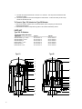
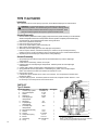
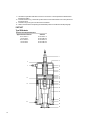
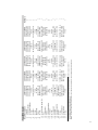
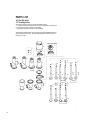
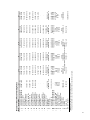
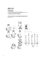
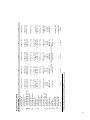
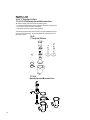
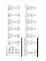
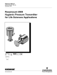
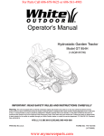
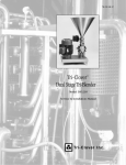
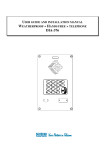
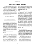
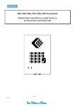
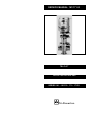
SERVICE MANUAL 161/171-93
TRI-FLO ®
AIR-ACTUATED VALVES
SERIES 161 • 161OY • 171 • 171OY
Tri-Clover Inc.
2
TABLE OF CONTENTS
INTRODUCTION ................................................................................................................................ 3
SAFETY .............................................................................................................................................. 4
VALVE DISASSEMBLY ...................................................................................................................... 4
VALVE INSPECTION ......................................................................................................................... 5
VALVE REASSEMBLY ....................................................................................................................... 5
TYPE 10 & 20 ACTUATOR ................................................................................................................ 7
TYPE 15 ACTUATOR ......................................................................................................................... 10
TYPE 280 ACTUATOR ....................................................................................................................... 11
PARTS LIST
161 SHUT OFF VALVES .................................................................................................................... 14
171 THROTTLING VALVES ............................................................................................................... 14
161 DIVERT VALVES ......................................................................................................................... 16
171 DIVERT VALVES ......................................................................................................................... 16
161-90 "Y" BODY SHUT OFF VALVE ................................................................................................ 18
171-10-90 TRI-FLO MANUALLY OPERATED MICROMETER VALVE ............................................. 18
INTRODUCTION
Thank you for purchasing a Tri-Clover Product!
This manual contains disassembly and assembly instructions, maintenance procedures, and complete
parts list of all Series 161 & 171 Air-Actuated Valves, 161-90 "Y" Body Shut Off Valve, 171-10-90
Manually Operated Micrometer Valve and actuators designed and manufactured by Tri-Clover Inc.,
Kenosha, Wisconsin.
READ THIS MANUAL carefully to learn how to service these valves. Failure to do so could result in
personal injury or equipment damage.
3
SAFETY
Safety is very important!
Included throughout this manual is the safety alert symbol you see to the left.
When you see this symbol be alert to the potential for personal injury.
SIGNAL WORDS: Like DANGER, WARNING, or CAUTION are used with a safety alert symbol.
DANGER-Immediate hazard which WILL result in severe personal injury or death. WARNING-Hazards or
unsafe practices which COULD result in personal injury or death. CAUTION-Hazards or unsafe practices
which COULD result in minor personal injury or product damage.
DO NOT attempt to modify any Tri-Clover product. To do so could create unsafe conditions and void
all warranties. DO NOT place any Tri-Clover product in an application where general product service
ratings are exceeded.
SAFETY LABELS below are placed on every valve. Do not remove any labeling on any Tri-Clover product.
Immediately replace any label that is missing.
WARNING
SPRING UNDER LOAD
ACTUATOR CYLINDER MAY EJECT WITH SUFFICIENT FORCE TO
CAUSE SERIOUS INJURY. REMOVE ACTUATOR FROM VALVE BEFORE
DISASSEMBLING ACTUATOR. REFER TO SERVICE BULLETIN.
Part Number 38-264
VALVE DISASSEMBLY
WARNING: To prevent personal injury, keep hands and tools out of and away
from valve bodies and stems when applying or releasing air to an actuator. The
actuator stem assembly moves with extreme force and suddenness.
•
When disassembling and assembling valve, bench area should be clean to prevent marring and
nicking of seats.
•
161 and 171 Series valves can be equipped with an open yoke. When so equipped, additional parts
are a type 316 stainless steel open yoke insert (located between valve actuator and upper body),
o-ring, clamp, washer, and lower stem. See parts list for related information.
Models 161-10, 21, 23, 30, 41, 43, and 90 Y Body
Models 171-10, 21, and 30
Normally Open: Type 10, 15, and 80 Actuators
1. Remove body clamp, lower body and gasket.
2. Apply air to actuator.
3. Remove valve stem.
4. Release air supply.
5. Remove o-ring from valve stem.
6. Remove actuator clamp, actuator, actuator o-ring, bonnet o-ring, stainless steel washer and upper
body or bonnet.
4
Normally Closed: Type 20 Actuator
1. Apply air to actuator.
2. Remove body clamp, lower body and gasket.
3. Release air supply.
4. Remove valve stem and valve stem o-ring.
5. Remove actuator clamp, actuator, actuator o-ring, bonnet o-ring, stainless steel washer and upper
body.
Models 161-27 and 47
Models 171-27
Normally Closed: Type 20 and 25 Actuators
1. Remove actuator clamp.
2. Apply air to actuator. Remove actuator, actuator o-ring and release air supply.
3. Remove body clamp, lower body and gasket.
4. Remove "E" retaining ring from valve stem.
5. Remove stainless steel washer and bonnet o-ring.
*
Actuator disassembly and service information starts on page five.
Models 171-10
Tri-Flo Manually Operated Micrometer Valve
Type 90 Actuator
1. Put valve in partially open position.
2. Remove body clamp, body, and gasket.
3. Remove clip on top of actuator.
4. Remove valve plug assembly and valve stem o-ring.
5. Unscrew knurled handle.
6. Replace friction buttons if the knurled handle turns freely. Use a notched screwdriver to remove
threaded bushing. This gives access to the friction button, spring and washer.
VALVE INSPECTION
Stem & Seat(s)
Carefully examine the rubber or PTFE valve plug seats for cracking, tearing, checking or excessive wear.
Leakage past the seat(s) may result from these types of irregularities.
Surface Finish
Inspect the valve stem and stem bore in valve upper body or bonnet for signs of galling. Replace both
components if galling exists. Galling will continue to occur if only one part is replaced and the other is
damaged.
Valve Body
Inspect the valve seats in the valve bodies for nicks, scratches and other irregularities. Leakage past the
seats may result from these type of irregularities.
Gaskets & O-ring(s)
Inspect for cuts, abrasions, flat spots or other damage that would cause leakage or ineffective cleaning.
Replace as necessary.
VALVE REASSEMBLY
WARNING: To prevent personal injury, keep hands and tools out of and away
from valve bodies and stems when applying or releasing air to an actuator.
The actuator stem assembly moves with extreme force and suddenness.
•
When disassembling and assembling valve, bench area should be clean to prevent marring and
nicking of seats.
5
Models 161-10, 21, 23, 30, 41, 43, and 90 Y Body
Models 171-10, 21, and 30
Normally Open: Type 10, 15, and 80 Actuators
1. Replace actuator o-ring, bonnet o-ring and stainless steel washer.
2. Clamp actuator to upper body or bonnet with actuator clamp.
3. Install o-ring on valve stem.
4. Apply air to actuator.
5. Insert valve stem through opening in upper valve body and into coupling unit in
actuator. Hold assembly together, then position vertically on top of work bench so that valve plug
rests on top of bench surface. Push down firmly on top of actuator and release air supply. If properly
coupled, stem cannot be removed.
6. Replace gasket, lower body and body clamp.
Normally Closed: Type 20 Actuator
1. Replace actuator o-ring, bonnet o-ring and stainless steel washer.
2. Clamp actuator to upper body or bonnet with actuator clamp.
3. Install o-ring on valve stem.
4. Insert valve stem through upper valve body stem opening and into coupling unit in actuator. Hold
assembly together, then position vertically on top of work bench so that valve plug rests on top of
bench surface. Push down firmly on top of actuator, then apply air to actuator. If properly coupled,
stem cannot be removed.
5. Replace gasket, lower body and body clamp.
6. Release air supply.
Models 161-27 and 47
Model 171-27
Normally Closed: Type 20 and 25 Actuators
1. Install o-ring on the valve stem and insert valve stem through upper body stem opening.
2. Replace bonnet o-ring and stainless steel washer.
3. Snap "E" retaining ring on valve stem.
4. Replace actuator o-ring. Apply air to actuator. Insert valve stem into coupling unit in actuator. Hold
complete assembly, then position vertically on work bench so that the valve plug rests on top of bench
surface. Push down firmly on top of actuator, then release air supply. If properly coupled, valve stem
cannot be removed.
5. Clamp actuator to upper body with actuator clamp. Be sure the valve bonnet and actuator are mated
properly before clamping. Release air supply.
6. Replace body gasket, lower body and body clamp.
Model 171-10
Tri-Flo Manually Operated Micrometer Valve
Type 90 Actuator
1. If friction buttons have been removed, reassemble by inserting spring, washer and friction button.
Screw the threaded bushing into bonnet with a notched screwdriver.
2. Screw knurled handle on actuator body.
3. Install valve stem o-ring and valve plug assembly.
4. Install clip through top of valve stem.
5. Install gasket, body and body clamp.
6
TYPE 10 AND 20 ACTUATORS
Introduction
The 10 & 20 actuators are spring return units used when a spring to open (10) or spring to close (20)
valve is required.
Installation
Connect air supply to the quick coupler fitting or the 1/8-27 FNPT port it is screwed into. Air supply
specifications: 35-50 psig.
WARNING: To prevent personal injury do not attempt to repair an old style
actuator. The old style actuator has a preloaded spring which will eject from the
actuator body with sufficient force to cause serious injury to anyone in the
immediate area. An old style actuator has no "step" between cylinder and
bonnet. See the illustration to the right.
WARNING: To prevent personal injury, hand pressure should be applied to the
top of the cylinder and bonnet Actuator cylinder may eject with sufficient force to
cause serious injury. Remove actuator from valve before disassembling
actuator. On 1" size valves, the actuator spring is not contained. Caution
should be used when the spring force is released.
OLD (No Step)
NEW (Step)
Actuator Disassembly
1. Place the two flats on the actuator bonnet in a vise. This will prevent the actuator bonnet from turning
when removing the cylinder.
2. Remove actuator cylinder from bonnet by applying a strap wrench to the cylinder and turning in a
counterclockwise direction until cylinder and bonnet can be separated.
3. Lift the cylinder off the bonnet.
4. Remove the piston assembly and spring.
5. Remove the actuator stem nut and lockwasher from the piston.
6. Remove the actuator stem from the piston.
7. Remove the o-ring from the actuator stem.
8. Remove the coupler from the actuator stem by applying wrenches to the flats on both parts.
9. Remove both o-rings from the bonnet and remove the bonnet from the vise.
Actuator Reassembly
1. Attach the coupler to actuator stem and replace o-ring on actuator stem.
2. Install new packings on the piston if required.
3. Apply Tri-Clover C137 lubricant to packings and felt seal after installation on the piston. Be sure
packing lip of the upper packing is toward the top of the piston. The lip of the lower packing must
be toward the bottom of the piston.
4. Install the actuator stem lockwasher and nut and tighten.
Type 210
• Place actuator stem through piston with coupler located on cavity side.
Type 220
• Place actuator stem through piston with coupler located on flat side.
5. Now insert the two flats of the actuator bonnet back in a vise.
6. Replace both o-rings in the bonnet.
7. Install the spring and piston.
Type 210
• Place the spring into position in the bonnet with the smaller retainer diameter toward the bonnet.
• Place the piston on the spring with piston cavity facing downward, enclosing the spring.
Type 220
• Set the piston on the bonnet with cavity facing upward.
• Insert the spring into the piston with the smaller retainer diameter towards the top. Be sure it is
centered.
8. Lubricate inside walls of cylinder with C137 lubricant and slowly slide the cylinder over the piston.
Use shim stock or a thin flat tool to compress the upper packing on the piston to get it started in the
cylinder.
7
9. Lubricate the cylinder threads with Tri-Clover C137 lubricant. This will prevent the stainless steel
threads from galling.
10. Thread the cylinder into the bonnet and tighten it until it bottoms. It will be necessary to use a strap
wrench for the last few turns.
To Convert a Type 210 Actuator to a Type 220 Actuator
1. Remove the cylinder, actuator stem, nut and lockwasher, piston and spring as outlined in the
Disassembly instructions.
2. Reassemble as outlined in steps #4 through #10 in the Actuator Reassembly section.
PARTS LIST
Type 10 & 20 Actautors
Actuator Assembly Part Numbers
Application
Shut-Off Valves 1", 11/2" & 2"
Shut-Off Valves 21/2" & 3"
Shut-Off Valves 4"
Divert Valves 11/2" & 2"
Divert Valves 21/2"
Divert Valves 3" & 4"
Type 10
25-161-210-1-S
25-161-210-2-S
25-161-210-4-S
25-161-210-3-S
25-161-210-4-S
25-161-210-5-S
Type 10
Type 20
25-161-220-1-S
25-161-220-2-S
25-161-220-4-S
25-161-220-3-S
25-161-220-4-S
25-161-220-5-S
Type 20
1
1
2
11
3
4
5
14
7
6
13
5
15
8
3
4
14
13
11
7
6
8
9
15
2
10
10
12
12
9
8
9
Description
Actuator body cylinder
Air coupler adapter
Nut
Lockwasher
Piston
Vee block packing
Felt seal
Spring assembly
O-ring, Type 10
Bonnet
Vented plug
O-ring
O-ring
Coupler stud
Coupler
25-161-210-1-S
25-161-210-1-01-S
25-361-210-06-S
NU1700H-SS
LWA1700-SS
25-361-210-02
17-97
17-101
25-161-210-1-07-S
10CPLO-3-73-1A
25-161-210-1-03-S
MS-105-58A-CP
17-2-U
17-35-U
25-161-210-1-09-S
37-95A-SS
25-161-210-2-S
25-161-210-2-01-S
25-361-210-06-S
NU1700H-SS
LWA1700-SS
25-361-210-02
17-97
17-101
25-161-210-2-07-S
10CPLO-3-73-1A
25-161-210-1-03-S
MS-105-58A-CP
17-2-U
17-35-U
25-161-210-1-09-S
37-95A-SS
25-161-210-3-S
25-161-210-3-01-S
25-361-210-06-S
NU1700H-SS
LWA1700-SS
25-361-210-02
17-97
17-101
25-161-210-3-07-S
10CPLO-3-73-1A
25-161-210-1-03-S
MS-105-58A-CP
17-2-U
17-35-U
25-161-210-1-09-S
37-95A-SS
Description
Actuator body cylinder
Air coupler adapter
Nut
Lockwasher
Spring assembly
Vee block packing
Felt seal
Piston
O-ring, Type 20
Bonnet
Vented plug
O-ring
O-ring
Coupler stud
Coupler
25-161-220-1-S
25-161-210-1-01-S
25-361-210-06-S
NU1700H-SS
LWA1700-SS
25-161-210-1-07-S
17-97
17-101
25-361-210-02
10CPLO-3-73-1A-U
25-161-210-1-03-S
MS-105-58A-CP
17-2-U
17-35-U
25-161-210-1-09-S
37-95A-SS
25-161-220-2-S
25-161-210-2-01-S
25-361-210-06-S
NU1700H-SS
LWA1770-SS
25-161-210-2-07-S
17-97
17-101
25-361-210-02
10CPLO-3-73-1A-U
25-161-210-1-03-S
MS-105-58A-CP
17-2-U
17-35-U
25-161-210-1-09-S
37-95A-SS
25-161-220-3-S
25-161-210-3-01-S
25-361-210-06-S
NU1700H-SS
LWA1700-SS
25-161-210-3-07-S
17-97
17-101
25-361-210-02
10CPLO-3-73-1A-U
25-161-210-1-03-S
MS-105-58A-CP
17-2-U
17-35-U
25-161-210-1-09-S
37-95A-SS
case two spares should be stocked.
Note: It is also recommended that a tube of C137 lubricant be stocked for servicing stainless steel actuators.
* It is recommended that one spare part of each item marked (*) with the exception of item 6, in which
Key #
1
2
3
4
5
*6
*7
8
*9
10
11
* 12
* 13
14
* 15
Type 20 Actuator
case two spares should be stocked.
Note: It is also recommended that a tube of C137 lubricant be stocked for servicing stainless steel actuators.
* It is recommended that one spare part of each item marked (*) with the exception of item 6, in which
Key #
1
2
3
4
5
*6
*7
8
*9
10
11
* 12
* 13
14
* 15
Type 10 Actuator
25-161-220-4-S
25-161-210-4-01-S
25-361-210-06-S
NU1700H-SS
LWA1700-SS
25-161-210-4-07-S
17-97
17-101
25-361-210-02
10CPLO-3-73-1A-U
25-161-210-1-03-S
MS-105-58A-CP
17-2-U
17-35-U
25-161-210-1-09-S
37-95A-SS
25-161-210-4-S
25-161-210-4-01-S
25-361-210-06-S
NU1700H-SS
LWA1700-SS
25-361-210-02
17-97
17-101
25-161-210-4-07-S
10CPLO-3-73-1A
25-161-210-1-03-S
MS-105-58A-CP
17-2-U
17-35-U
25-161-210-1-09-S
37-95A-SS
25-161-220-5-S
25-161-210-6-01-S
25-361-210-06-S
NU1700H-SS
LWA1700-SS
25-161-210-5-07-S
17-97
17-101
25-361-210-02
10CPLO-3-73-1A-U
25-161-210-1-03-S
MS-105-58A-CP
17-2-U
17-35-U
25-161210-1-09-S
37-95A-SS
25-161-210-5-S
25-161-210-6-01-S
25-361-210-06-S
NU1700H-SS
LWA1700-SS
25-361-210-02
17-97
17-101
25-161-210-5-07-S
10CPLO-3-73-1A
25-161-210-1-03-S
MS-105-58A-CP
17-2-U
17-35-U
25-161210-1-09-S
37-95A-SS
No. Req'd
1
1
1
1
1
2
1
1
1
1
1
1
1
1
1
No. Req'd
1
1
1
1
1
2
1
1
1
1
1
1
1
1
1
TYPE 15 ACTUATOR
Introduction
The 15 actuator is an air to close-spring to open unit, which utilizes a diaphragm for reduced friction.
WARNING: To prevent personal injury, remove actuator from valve before
disassembling actuator. The actuator spring is not contained. Although preload
force is low, caution should be used when the spring forces is released. Hand
pressure should be applied to the top of the cylinder to restrict its travel.
Actuator Disassembly
1. Remove actuator cylinder from bonnet by applying strap wrench to the cylinder and turning in counterclockwise
direction until cylinder and bonnet can be separated. When the cylinder is completely unscrewed the spring
force will push it up. Apply hand pressure as noted in warning note above.
2. Remove the cylinder from the bonnet.
3. Remove the spring from the bonnet.
4. Remove air coupler adapter, gasket, and sealing nut.
5. Slide cylinder off actuator internals.
6. Slide body insert and diaphragm from outer diaphragm clamp/retainer.
7. Remove coupler, washers, and retainer assembly nut. Retainer nut may be readily removed by
inserting a punch in a hole in the retainer nut face, and tapping the nut in a counterclockwise direction.
8. Separate top and inner diaphragm clamp/retainers, freeing diaphragm.
Actuator Reassembly
1. Spray diaphragm with a silicone spray lubricant and install between top and inner diaphragm
clamp/retainers.
2. Install retainer nut assembly, washers, and coupler.
3. Roll diaphragm onto outer diaphragm clamp/retainer. Slide body insert onto outer diaphragm
clamp/retainer.
4. Carefully slide cylinder over diaphragm so that diaphragm is not abraded or torn.
5. Spray gasket with silicone spray lubricant. Install sealing nut, gasket, and air coupler adapter.
NOTE: Now insert the two flats of the actuator bonnet back into a vise.
6. Place spring in bonnet.
7. Lubricate the cylinder threads with Tri-Clover C137 lubricant. This will prevent the stainless steel
threads from galling.
8. Compress spring by hand. Thread the cylinder into the bonnet, and tighten it until it "bottoms". It will
be necessary to use a strap wrench for the last few turns.
2
PARTS LIST
Type 15 Actuator
Key #
1
2
3
4
5
*7
8
9
10
11
*12
13
14
15
*16
10
Description
Actuator body cylinder
Air coupler adapter
Gasket
Sealing nut
Outer diaphragm
clamp/retainer
Diaphragm
Top diaphragm
clamp/retainer
Inner diaphragm
clamp/retainer
Nut-retainer assembly
Washer
Coupler
Compression spring
Bonnet
Vented plug
O-ring
3
4
Part Number
25-263B-01-S
37-5-S
17-88
13-78-S
36-55
No. Req'd.
1
1
1
1
1
35-1
36-15
1
1
36-3
1
13-15
15-47
37-13A-SS
4-2-S
12-410-2
MS-105-58A-CP
17-2-U
1
1
1
1
1
1
1
10
11
1
8
6
9
7
12
13
15
14
16
* It is recommended that one spare part be stocked
for each item marked (*).
Note: It is also recommended that a tube of C137 lubricant
be stocked for servicing stainless steel actuators.
TYPE 280 ACTUATOR
Introduction
For regular open and closed operation, apply air to the top center air connection. This will fully close the
valve bottom port. Release the air supply to fully open the valve bottom port. The actuator is normally
open to the bottom port.
Installation
For intermediate or split-flow operation, apply air to the side air connection. This will position the valve in
approximately mid position for split flow, depending on how the actuator is adjusted. Adjust the mid
position as follows:
1.
2.
3.
4.
Loosen the jamnut on the top center of the actuator.
Use a wrench on the air coupler hex fitting and rotate the complete air guide stem.
Turn clockwise to give more restriction to the valve bottom port.
Turn counterclockwise to give more restriction to the top port.
NOTE: Use two 3-way solenoid valves to control air to the above connections.
Actuator Disassembly
1. Secure the two flat edges on the actuator ferrule in a vise. This will keep the bonnet from turning
when removing the actuator cylinder.
2. Remove the actuator cylinder from the bonnet by applying a strap wrench to the cylinder and turning
counterclockwise.
3. Lift the spring from the bonnet and remove the bonnet from the vise.
4. Slowly slide the primary piston out of the cylinder.
5. Use suitable wrenches on the machined flats of the coupler and remove the stem nut and lockwasher
from the piston.
6. Remove the coupler stud from the piston. Use suitable wrenches to remove the coupler from the
coupler stud.
7. Remove the jamnut from the upper bonnet.
8. Remove the air guide stem by rotating counterclockwise and removing from inside the cylinder.
9. Slowly slide the secondary piston out of the cylinder.
NOTE: It is not necessary to remove the upper bonnet from the cylinder unless the o-ring does not
seal properly.
Actuator Reassembly
1. Install the upper o-ring and Quad ring on the secondary piston. Lightly coat the inside of the cylinder
wall and the O.D. of the secondary piston with lubricant.
2. Slowly slide the secondary piston into the cylinder. Use shim stock or a thin flat tool to compress the
Quad ring on the piston to get it started in the cylinder. Make sure the piston cavity faces out. Slide
the piston into the cylinder until it seats against the stop on the upper bonnet.
3. Install the o-ring on the air guide stem. Insert the stem into the piston bore and out through the upper
bonnet. Turn in a clockwise direction to the desired position.
4. Install the jamnut to the air guide stem.
5. Install the coupler to the coupler stud. Install the o-ring on the coupler stud. Insert the assembly into
the piston so that the coupler is on the same side as the piston cavity. Secure with the lockwasher
and stem nut.
6. Secure the lower bonnet in a vise and place the spring assembly over the hub in the bonnet. Place
the small diameter of the spring cage into the bonnet first.
7. Apply Tri-Clover C137 lubricant to the O.D. of packings and the felt seal and install in the piston.
Place the piston, with the piston cavity facing the spring, over the spring. Be sure the packing lip of
the upper packing is toward the top of the piston and the lip of the lower packing is toward the
bottom of the piston.
8. Lubricate inside walls of cylinder with C137 lubricant, and slowly slide the cylinder over the piston.
Use a shim stock or a thin, flat tool to compress the upper packing on the piston to get it started in
the cylinder.
11
9. Lubricate the cylinder threads with Tri-Clover C137 lubricant. This will prevent the stainless steel
threads from galling.
10. Install the bonnet o-ring. Thread the cylinder into the bonnet until it bottoms. Use a strap wrench for
the last few turns.
11. Install the o-ring in the groove on the lower bonnet ferrule.
12. Refer to the instructions for adjusting the intermediate position in the INSTALLATION paragraph.
PART LIST
Type 280 Actuator
Actuator Assembly Part Numbers
Application-Divert Valves
161-21-280-11/2
161-21-280-2
161-21-280-21/2
161-21-280-3
161-21-280-4
Actuator
25-161-280-1-S
25-161-280-2-S
25-161-280-3-S
25-161-280-4-S
25-161-280-5-S
1
2
9
3
6
4
10
5
7
12
16
8
11
13
15
14
17
18
19
21
23
22
20
24
12
13
Description
Jamnut
Actuator bonnet
Air coupler adapter
O-ring
Cylinder
O-ring
Quad ring
Piston
O-ring
Air guide stem assembly
Nut
Lockwasher
Piston
Vee block packing
Felt seal
O-ring
Coupler stud
Coupler
Spring assembly
Spacer
O-ring
Lower bonnet
Plug, vented
O-ring
25-161-280-1-S
25-361-280-18-S
25-161-280-1-03
25-361-210-06-S
17-99-U
25-161-280-1-01-S
17-4-U
17-137Q
25-161-280-1-02
60YM23-1-34-U
25-161-280-1-16-S
NU1700H-SS
LWA1700-SS
25-361-210-02
17-97
17-101
17-35-U
25-161-210-1-09-S
37-95A-SS
25-161-210-1-07-S
25-161-280-22-1
10CPLO-3-73-1A-U
25-161-210-1-03-S
MS-105-58A-CP
17-2-U
25-161-280-2-S
25-361-280-18-S
25-161-280-2-03
25-361-210-06-S
17-99-U
25-161-280-2-01-S
17-4-U
17-137Q
25-161-280-2-02
60YM23-1-34-U
25-161-280-2-16-S
NU1700H-SS
LWA1700-SS
25-361-210-02
17-97
17-101
17-35-U
25-161-210-1-09-S
37-95A-SS
25-161-210-2-07-S
10CPLO-3-73-1A-U
25-161-210-1-03-S
MS-105-58A-CP
17-2-U
25-161-280-3-S
25-361-280-18-S
25-161-280-3-03
25-361-210-06-S
17-99-U
25-161-280-3-01-S
17-4-U
17-137Q
25-161-280-3-02
60YM23-1-34-U
25-161-280-3-16-S
NU1700H-SS
LWA1700-SS
25-361-210-02
17-97
17-101
17-35-U
25-161-210-1-09-S
37-95A-SS
25-161-210-3-07-S
10CPLO-3-73-1A-U
25-161-210-1-03-S
MS-105-58A-CP
17-2-U
for which two spares should be stocked.
Note: It is also recommended that a tube of C137 lubricant be stocked for servicing stainless steel actuators.
* It is recommended that one spare part be stocked for each item marked (*), with the exception of item 14,
Key #
1
2
3
*4
5
*6
*7
8
*9
10
11
12
13
* 14
* 15
* 16
17
* 18
19
20
* 21
22
23
24
Type 280 Actuator
25-161-280-4-S
25-361-280-18-S
25-161-280-4-03
25-361-210-06-S
17-99-U
25-161-280-4-01-S
17-4-U
17-137Q
25-161-280-4-02
60YM23-1-34-U
25-161-280-4-16-S
NU1700H-SS
LWA1700-SS
25-361-210-02
17-97
17-101
17-35-U
25-161-210-1-09-S
37-95A-SS
25-161-210-4-07-S
10CPLO-3-73-1A-U
25-161-210-1-03-S
MS-105-58A-CP
17-2-U
25-161-280-5-S
25-361-280-18-S
25-161-280-5-03
25-361-210-06-S
17-99-U
25-161-280-5-01-S
17-4-U
17-137Q
25-161-280-5-02
60YM23-1-34-U
25-161-280-5-16-S
NU1700H-SS
LWA1700-SS
25-361-210-02
17-97
17-101
17-35-U
25-161-210-1-09-S
37-95A-SS
25-161-210-5-07-S
10CPLO-3-73-1A-U
25-161-210-1-03-S
MS-105-58A-CP
17-2-U
No. Req'd.
1
1
1
1
1
1
1
1
1
1
1
1
1
2
1
1
1
1
1
1
1
1
1
PARTS LIST
161 Shut Off Valves
171 Throttling Valves
All orders for repair parts must contain the following data.
1. Complete model number (located on actuator nameplate), including size.
2. Valve serial number (located on nameplate).
3. Description and part number from the parts list.
The following exploded view and accompanying parts list facilitate ordering
repair parts from the factory. All parts illustrated are indexed to the parts
list by key number.
Open Yoke Option
15
16
11
14
10
14
8B
8A
8
9
16A
4" Only
14
14
9
9
9
4C
4A
or
4C
9
5
4A
4B
4D
6
Open Yoke
3
13
13
2
9
9
13
12
9
4" Only
13
12
9
1
4F
4E
4H
Open Yoke
14
9
4G
4B
or
4D
15
12-102-2-316
7-226T-2-316
7-226C-2-316
17-1-U
17-5-U
15-31-S
17-35-U
12-102-11/2-316
7-226T-11/2-316
7-226C-11/2-316
17-1-U
17-5-U
15-31-S
17-35-U
12-102-21/2-316
7-226T-21/2-316
7-226C-21/2-316
17-5-U
17-17-U
15-26-S
17-163-U
19-1292-21/2-316
17-62-21/2-U
H13MHHM-21/2-S
19-1299-2 / -316
1 2
19-986-2 1/2-316
19-748-2 / -316
1 2
19-1286-21/2-316
19-1258-21/2-316
19-269-21/2-316
19-627-21/2-316
7-241A-21/2-316
2 1/2"
7-225T-21/2-316
7-225C-21/2-316
16-5-S
16-5-S
16-5-S
13MHHM-2-S
13-MHHM-2-S
13MHHM-2-S
See appropriate Actuator Section in this manual
12-491-1-S
12-491-1-S
12-491-21/2-S
-
19-1292-2-316
17-62-2-U
H12MHHM-2-S
19-1299-2-316
19-986-2-316
19-748-2-316
19-1286-2-316
19-1258-2-316
19-269-2-316
19-1292-11/2-316
17-62-11/2-U
H13MHHM-11/2-S
19-1299-1 / -316
1 2
19-986-11/2-316
19-748-1 / -316
1 2
19-1286-11/2-316
19-1258-11/2-316
19-269-11/2-316
19-627-2-316
7-241A-2-316
7-241A-11/2-316
19-627-11/2-316
2"
7-225T-2-316
7-225C-2-316
11/2"
7-225T-11/2-316
7-225C-11/2-316
* Note: Specify the type of port connections required.
• It is recommended that one of each of these items be stocked as spare parts.
•
*
*
•
•
•
•
•
•
•
•
•
•
•
Description
1"
Valve, lower body-Model 10
7-225T-1-316
Valve, lower body-Model 30
7-225C-1-316
Valve, lower bodyModels 27 & 47
4A Valve plug assemblyModels 161-10 & 30
19-627-1-316
4B Valve Plug Assembly
Model 171-10 & 30
19-269-1-316
4C Valve plug assemblyModels 161OY-10 & 30
19-1258-1-316
4D Valve plug assemblyModels 171OY-10 & 30
19-1286-1-316
4E Valve plug assemblyModels 161-27 & 47
4F Valve plug assemblyModel 171-27
4G Valve plug assemblyModels 161OY-27 & 47
4H Valve plug assemblyModels 171OY-27
5
Body gasket
17-62-11/2-U
6
Body clamp
H13MHHM-11/2-S
8
Valve bonnetModels 10 & 30
12-102-11/2-316
8A Valve, upper body-Model 27
8B Valve, upper body-Model 47
9
O-ring, valve plug stem
17-1-U
10
O-ring, valve bonnet
17-5-U
11
Stainless steel washer
15-31-S
12
Open Yoke O-Ring
17-35-U
13
E ring-valve plug stemModels 27 & 47
14
Actuator clamp
13MHHM-2-S
15
Actuator
16
Open Yoke
12-491-1-S
16A OY - Bonnet
-
Key #
* 1
* 2
* 3
161 and 171 Shut Off and Throttling Valves
16-5-S
13MHHM-2-S
12-102B-4-316
12-491-21/2-S
-
12-102-4-316
7-226T-4-316
7-226C-4-316
01-1165-11-U
17-17-U
15-26-S
-
17-62-41/2-U
H13MHHM-4-S
-
-
19-748-4-316
19-269-4-316
19-627C-4-316
19-269-4-316
19-627C-4-316
7-241A-4-316
4"
7-225T-4-316
7-225C-4-316
16-5-S
13MHHM-2-S
12-102-3-316
7-226T-3-316
7-226C-3-316
17-5-U
17-17-U
15-26-S
17-163-U
19-1292-3-316
17-62-3-U
H13MHHM-3-S
19-1299-3-316
19-986-3-316
19-748-3-316
19-1286-3-316
19-1258-3-316
19-269-3-316
19-627-3-316
7-241A-3-316
3"
7-225T-3-316
7-225C-3-316
PARTS LIST
161 Divert Valves
171 Divert Valves
All orders for repair parts must contain the following data.
1. Complete model number (located on actuator nameplate), including size.
2. Valve serial number (located on nameplate).
3. Description and part number from the parts list.
The following exploded view and accompanying parts list facilitate ordering
repair parts from the factory. All parts illustrated are indexed to the parts
list by key number.
Open Yoke
12
13
11
10
11
9
13B
4" Only
14
8
14
8
7
8
8
8
6
13A
4" Only
4
3A
5
3B
3D
3C
Open Yoke
Option
1
2
16
3A or 3C
4" Only
17
7-226T-21/2-316
19-1291-21/2-316
17-62-21/2-U
H13MHHM-21/2-S
19-1257-21/2-316
7-225C-21/2-316
79-647-21/2-316
19-281-21/2-316
7-225T-21/2-316
2 1/2"
7-226T-3-316
19-1291-3-316
17-62-3-U
H13MHHM-3-S
19-1257-3-316
7-225C-3-316
19-647-3-316
19-281-3-316
7-225T-3-316
3"
----17-35-U
--17-35-U
--17-163-U
---
--17-163-U
---
7-226C-2-316
7-226C-21/2-316
7-226C-3-316
17-1-U
17-5-U
17-5-U
17-5-U
17-17-U
17-17-U
15-31-S
15-26-S
15-26-S
13MHHM-2-S
13MHHM-2-S
13MHHM-2-S
See appropriate Actuator Section in this manual.
12-491-1-S
12-491-2 1/2-S
12-491-2 1/2-S
7-226T-2-316
---
12-491-1-S
7-226C-11/2-316
17-1-U
17-5-U
15-31-S
13MHHM-2-S
7-226T-1 1/2-316
19-1291-2-316
17-62-2-U
H13MHHM-2-S
19-1257-2-316
19-1257-11/2-316
19-1291-11/2-316
17-62-11/2-U
H13MHHM-11/2-S
7-225C-2-316
19-647-2-316
19-281-2-316
7-225T-2-316
7-225T-1 1/2-316
7-225C-11/2-316
19-947-11/2-316
19-281-11/2-316
2"
11/2"
* Note: Specify the type of port connections required.
• It is recommended that one each of these items be stocked as spare parts.
•
•
*
*
•
•
•
•
•
*
Description
Valve, lower bodyModels 21 & 41
2
Valve, lower bodyModels 23 & 43
3A Valve Plug Assembly - 161
3B Valve Plug Assembly - 171
3C Valve Plug Assmebly
Model 161-OY
3D Valve Plug Assmebly
Model 171-OY
4
Body gasket
5
Body clamp
6
Valve, upper bodyModels 21 & 23
7
Valve, upper bodyModels 41 & 43
8
O-ring, valve plug stem
9
O-ring, valve bonnet
10
SS Washer
11
Actuator clamp
12
Actuator
13
Open Yoke
13A Open Yoke Body
Models 21 & 23
13B Open Yoke Body
Models 41 & 43
14
O-ring
Key #
* 1
161 and 171 Divert Valves
7-226CB-4-316
17-163-U
7-226TB-4-316
---
7-226CA-4-316
1-1165-11-U
17-17-U
15-26-S
13MHHM-2-S
7-226TA-4-316
--17-62-41/2-U
H13MHHM-4-S
19-647A-4-316
7-225C-4-316
19-647A-4-316
---
7-225T-4-316
4"
PARTS LIST
161-90 "Y" Body Shut Off Valve
171-10-90 Tri-Flo Manually Operated Micrometer Valve
All orders for repair parts must contain the following data.
1. Complete model number (located on actuator nameplate), including size.
2. Valve serial number (located on nameplate).
3. Description and part number from the parts list.
The following exploded view and accompanying parts list facilitate ordering
repair parts from the factory. All parts illustrated are indexed to the parts
list be key numbers.
161-90
"Y" Body Shut Off Valve
10
5
7
5A
5
2A
2
11
8
7
9
3
6
4
1
171-10-90
Manually-Operated Micrometer Valve
7
8
11
12
6
9
3
10
5
4
2
1
1A
18
19
Description
Valve, "Y" Body
Valve, plug assembly
OY Valve, plug assembly
Body, gasket
Body, clamp
O-ring, valve plug stem
OY O-ring, valve plug stem
Valve, bonnet
Actuator clamp
Stainless steel washer
O-ring, valve bonnet
Actuator-Type 10
Actuator-Type 20
Actuator-Type 30
Yoke
1"
60YMMP-1-51-316
19-821-1-316
19-1259-1-316
60YM-1-15B-U
16-138-S
17-1-U
17-35-U
12-15-316
13MHHM-2-S
15-31-S
17-5-U
25-161-210-90-1-S
25-161-220-90-1-S
25-161-230-90-1-S
12-491-1-S
11/2"
60YMMP-11/2-51-316
19-821-11/2-316
19-1259-11/2-316
40MP-U-21/2
H13MHHM-2-S
17-1-U
17-35-U
12-16-316
13MHHM-2-S
15-31-S
17-5-U
25-161-210-1-S
25-161-220-1-S
25-161-230-1-S
12-491-1-S
Description
Body - Tee
Body - Cross
Stem
Gasket
Clamp
O-ring
Bonnet
Clip
Knurled handle
Spring
Washer
Friction button
Threaded bushing
1"
7-225T-1-316
7-225C-1-316
19-797-1-316
17-62-11/2-U
H13MHHM-11/2-S
17-1-U
12-368-11/2-316
10-1164-03-S
8-1-S
4-36
15-110
24-21
40-7-S
11/2"
7-225T-11/2-316
7-225C-11/2-316
19-797-11/2-316
17-62-11/2-U
H13MHHM-11/2-S
17-1-U
12-368-11/2-316
10-1164-03-S
8-1-S
4-36
15-110
24-21
40-7-S
2"
7-225T-2-316
7-225C-2-316
19-797-2-316
17-62-2-U
H13MHHM-2-S
17-1-U
12-368-2-316
10-1164-03-S
8-1-S
4-36
15-110
24-21
40-7-S
2"
60YMMP-2-51-316
19-821-2-316
19-1259-2-316
40MP-U-3
H13MHHM-21/2-S
17-1-U
17-35-U
12-17-316
13MHHM-2-S
15-31-S
17-5-U
25-161-210-3-S
25-161-220-3-S
25-161-230-3-S
12-491-1-S
§ Note: Quantity required for 1", 11/2" and 2" is 2 each; 21/2", 3" and 4" are 3 each.
* Note: Specify the type of port connections required.
• It is recommended that one each of these items be stocked as spare parts except item 10 as noted.
Key #
* 1
* 1A
2
• 3
4
• 5
6
• 7
8
§ 9
§ 10
• § 11
§ 12
171-10-90 Tri-Flo Manually Operated Micrometer Valve
* Note: Specify the type of port connections required.
• It is recommended that one each of these items be stocked as spare parts.
Key #
* 1
• 2
• 2A
• 3
4
• 5
• 5A
6
7
8
• 9
10
10
10
11
161-90 "Y" Body Shut Off Valve
21/2"
7-225T-21/2-316
7-225C-21/2 -316
19-797-21/2-316
17-62-21/2-U
H13MHHM-21/2-S
17-5-U
12-368-21/2-316
10-1164-04-S
8-18-S
4-36
15-110
24-21
40-7-S
21/2"
60YMMP-21/2-51-316
19-821-21/2-316
19-1259-21/2-316
40MP-U-4
13MHHM-161-90-21/2-S
17-5-U
17-163-U
12-18A-316
13MHHM-2-S
15-26-S
17-17-U
25-161-210-4-S
25-161-230-4-S
12-491-21/2-S
3"
7-225T-3-316
7-225C-3-316
19-797-3-316
17-62-3-U
H13MHHM-3-S
17-5-U
12-368-3-316
10-1164-04-S
8-18-S
4-36
15-110
24-21
40-7-S
3"
60YMMP-3-316L
19-821-3-316
19-1259-3-316
40MP-U-5
16-94-S
17-5-U
17-163-U
12-19-316
13MHHM-2-S
15-26-S
17-17-U
25-161-210-5-S
25-161-230-5-S
12-491-21/2-S
4"
7-225T-4-316
7-225C-4-316
19-797-4-316
17-62-41/2-U
H13MHHM-4-S
17-5-U
12-368-4-316
10-1164-04-S
8-18-S
4-36
15-110
24-21
40-7-S
4"
E60YMMP-4-51-316L
19-821-4-316
19-1259-4-316
60YM-4-15B-U
13MHHVM-161-90-4-S
17-5-U
17-163-U
12-20-316
13MHHM-2-S
15-26-S
17-17-U
On Application
25-161-230-7-S
12-491-21/2-S
Tri-Clover
manufactures
a complete line of
TRI-WELD® fittings
TRI-CLAMP® fittings
BEVEL SEAT fittings
POSITIVE PUMPS
CENTRIFUGAL PUMPS
AUTOMATIC Air Actuated VALVES
STAINLESS STEEL TUBING
AUTOMATED FLOW CONTROL SYSTEMS
Terms, Warranty Provisions, Notice of Claims and Limitation of Liability
Prices and all terms and conditions of sale are established
in current price sheets and are subject to change without notice.
All orders are subject to acceptance by Tri-Clover Inc. at its
Kenosha, Wisconsin or Distribution Center* offices only. No
assignment of the purchaser’s rights may be made without
consent of Tri-Clover Inc.
Each Tri-Clover item is warranted to be free from manufacturing defects for a period of one (1) year from the date of
shipment, providing it has been used as recommended and in
accordance with recognized piping practice, and providing it has
not been worn out due to severe service, such as encountered
under extremely corrosive or abrasive conditions.
This warranty is expressly in lieu of any other warranties, express or implied, including but not limited to, any
implied warranty of merchantability or fitness for a particular purpose.
All claims must be in writing and must be mailed or delivered
by purchaser within thirty (30) days after purchaser learns of the
facts upon which such claim is based. Any claim not made in
writing and within the time period specified above shall be
deemed waived.
Purchaser’s sole and exclusive remedy and Tri-Clover
Inc.’s maximum liability for claims arising hereunder or for
negligence for any and all losses and damages resulting
from any cause shall be either the repair or replacement of
defective items or, at Tri-Clover Inc.’s option, the refund of
the purchase price for such items. In no event, including in
the case of a claim for negligence, shall Tri-Clover be liable
for incidental or consequential damages including loss of
profits.
No person, including any representative, employee or agent
of Tri-Clover, is authorized to assume on behalf of Tri-Clover Inc.,
any liability or responsibility in addition to or different from that
described in this provision. Any and all representations, promises, warranties or statements that are in addition to or different
from the terms of this provision are of no force or effect.
*Distribution Centers in Union City, California and Memphis,
Tennessee
Tri-Clover Inc.
An Alfa Laval Flow Company
9201 Wilmot Road
Kenosha, Wisconsin 53141-1413
414-694-5511
FAX: 414-694-7104
International Sales: 414-697-3170
FAX: 414-694-8188
Tri-Clover Canada Ltd.
P.O. Box 430
Brantford, Ontario N3T 5P3
519-753-4158
FAX: 519-759-8709
161/171-93
Printed in November 1993