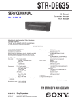
1
KGC-222 Revision History KGC-222 Service Manual Doc No: 0093822202 Document Revision History No. Doc. No-Rev. No. Date revised Revised content (Y/M/D) 0 0093822202-00 2014/03/13 First edition 1 0093822202-01 2014/09/18 System Configuration, Chapter 2, Chapter 3 2 3 4 5 6 7 8 9 10 Document No. Revised Version Norm When part of the document needs to be revised, the document has advanced revision number. The document No. is indicated at the lower right side on the cover and at the left or right side of the footer region of each page. © 2014 Koden Electronics Co., Ltd. All rights reserved. No part of this publication may be reproduced, transmitted, translated in any form by any means without the written permission of Koden Electronics Co., Ltd. The technical descriptions contained in this publication are subject to change without notice. Koden assumes no responsibility for any errors, incidentals or consequential damages caused by misinterpretation of the descriptions contained in this publication. 0093822202-01 i Important Notice KGC-222 Important Notice For copy and transcription of this Service Manual (hereinafter referred to as this manual), permission from Koden is needed. Koden prohibits the un-authorized copy and transcription of this manual. If this manual is lost or damaged, consult a dealer of Koden or Koden. The specification of the products and the contents in this manual are subject to change without notice. The contents displayed on the menu of product may be different from the expression of this manual. The fonts and shapes of the keys and menus in the illustration may differ from the actual ones, and some parts may be omitted. Koden is not liable for damages and troubles arisen from misunderstanding of the contents in this manual. Koden is not liable for any damages caused by earthquake, lightning, wind and flood damage and fire for which Koden is not responsible, and actions by third parties, other accidents, customer’s unintended error/abuse and the use under other abnormal conditions. Koden is not liable for damages of accompaniment (change/loss of memorized content, loss of business profit, stop of business) arisen from use or failure of our products. If the stored data are changed or lost, irrespective of causes of troubles and damages, Koden is not liable for them. Koden is not liable for any damages arisen from malfunction caused by combination of software and connected equipment in which Koden is not engaged. ii 0093822202-01 KGC-222 For Your Safe Operation For Your Safe Operation Pictograms used in this Service Manual The following pictograms are used in this manual. The meaning of each symbols shall be well understood and the maintenance and inspection shall be carried out. Symbol Meaning Mark for warning This mark denotes that there is a risk of death or serious injury when Warning dealt with incorrectly. Mark for danger of high voltage This mark denotes that there is a risk of death or serious injury due to electric shock when dealt with incorrectly. Mark for caution This mark denotes that there is a risk of slight injury or damages of Caution devices when dealt with incorrectly. Mark for prohibition This mark denotes prohibition of specified conducts. Description of the prohibition is displayed near the mark. Precautions on equipment Warning Warning Caution 0093822202-01 Be careful of high voltage inside High voltage, which may risk you life, is used. This high voltage may remain in the circuit even after the power is switched off. To prevent contact with the high voltage circuits accidentally, a protective cover or the label with this mark is provided on the high voltage circuit. When the inside is to be checked, ensure to switch off the power and to discharge the residual voltage for safety. An engineer authorized by Koden shall carry out the inspection and maintenance works. Power off in the boat An accidental power-on during works may result in worker’s electrification. To prevent such accident in advance, ensure that power in the boat and on the equipment are switched off. Furthermore, it is safer to hang a caution tag saying “Under work” near the power switch of equipment. Be careful of dust Inhaled dust may cause respiratory affection. At the time of cleaning the inside of equipment, be careful not to inhale dust. Wearing a safety mask is recommended. Caution on location of installment The equipment shall not be installed at locations which are excessively damp and suffers from water drops. Otherwise, dew condensation may occur inside the display screen, and corrosion may occur inside the unit box. iii For Your Safe Operation Caution Caution KGC-222 Measures against static electricity Static electricity may be generated from the carpet on the floor in the cabin or clothes made of synthetic fiber, and it may destroy the electronic components on circuit boards. The circuit boards shall be handled with appropriate measures against static electricity. Caution at installation of transducer Transducer shall be installed at locations where there is no effect by bubble and noise. Bubble and noise may seriously degrade the performance of this equipment. Precautions on handling Warning Warning Caution Caution Caution iv No disassembly or modification of this equipment is allowed. It may lead to failure, firing, smoking or electric shock. In case of failure, please contact Koden’s dealers or Koden. In case of smoking or firing, switch off the power in the boat and of this equipment. It may lead to firing, electric shock or damages. Be careful of residual high voltage High voltage may remain in capacitors for several minutes after switching off the power. Before inspection of the inside, please wait at least 5 minutes after switching off or discharge the residual electricity in an appropriate manner. Then, start the work. The information displayed on this equipment is not intended to use for your navigation. For your navigation, be sure to see the specified materials. Please use the specified fuses. If un-specified fuses are used, they may cause firing, smoking or damages. Be sure to submerge the transducer in water before transmission. If not, it may be damaged. 0093822202-01 KGC-222 Contents Contents Document Revision History .............................................................................................. i Important Notice .............................................................................................................. ii For Your Safe Operation ................................................................................................. iii Contents ........................................................................................................................ v Introduction.................................................................................................................... vii System Configuration ....................................................................................................viii System Configuration (with Junction box) ...................................................................... ix Pin Assignment of Rear Connector ................................................................................. x Connection with Junction box (JB-35) ............................................................................ xi Configuration of Equipment ........................................................................................... xii External view and dimensions ...................................................................................... xiv Specifications ............................................................................................................... xvi Chapter 1 Installation .......................................................................... 1-1 1.1 Items of Caution on Installation ............................................................................1-1 Unpacking the components ................................................................................ 1-1 Appearance varification of each unit and accessories........................................ 1-1 Selection of location for installation .................................................................... 1-1 Laying and Connection of Cable ........................................................................ 1-3 Confirmation after Installation ............................................................................. 1-4 1.2 Installation of Display unit ....................................................................................1-5 Table mounting ................................................................................................... 1-5 Flush mounting ................................................................................................... 1-6 1.3 Installation of GPS antenna GA-12 ......................................................................1-7 Antenna cable layout method ............................................................................. 1-7 Installation of GPS antenna ................................................................................ 1-8 Angle compensation of Antenna ......................................................................... 1-9 Connecting and waterproofing the connector ..................................................... 1-9 Connecting the 60m antenna cable kit CW-394.KIT to GPS antenna .............. 1-10 Installing the bird protector to Antenna unit ....................................................... 1-11 1.4 Wiring.................................................................................................................1-12 Chapter 2 Maintenance and Troubleshooting ..................................... 2-1 2.1 Inspection ...............................................................................................................2-1 2.2 Cleaning .................................................................................................................2-1 Display unit ......................................................................................................... 2-1 2.3 If you suspect a trouble ..........................................................................................2-1 2.4 Error Message ........................................................................................................2-2 2.5 Initialize ..................................................................................................................2-4 0093822202-01 v Contents KGC-222 Initialization of KGC-222 is performed. ............................................................... 2-4 Chapter 3 Detail of the serial output data ............................................ 3-1 3.1 Output data format ............................................................................................... 3-1 3.2 Details of the output data format .......................................................................... 3-1 3.3 Output data specification ..................................................................................... 3-1 3.4 Details of output sentences ................................................................................. 3-1 Chapter 4 Technical references ........................................................... 4-1 vi 4.1 Maintenance parts list .......................................................................................... 4-1 4.2 Exploded view drawing ........................................................................................ 4-2 4.3 Block diagram ...................................................................................................... 4-3 0093822202-01 KGC-222 Introduction Introduction KGC-222 is a GPS compass. Through the use of GPS satellites, it outputs the heading of vessel with a high degree of accuracy by calibrating the phase difference of two GPS antennas. The main features of this unit are as follows: KGC-222 consists of two main components, Display and Antenna. Display unit has processor, receiver and LCD display built-in. KGC-222 has internal electronic compass as backup sensor. This enables the backup sensor to output heading even if the GPS signals are interrupted in such case as the vessel passing under a bridge. KGC-222 can also output pitch / roll and heaving data. When KGC-222 is used with an echo sounder with heaving compensation function, you can obtain stable sea bottom without effect from heaves and waves. It has 3 heading data output ports. Up to 5 ports will be available with connecting an optional junction box. 0093822202-01 vii System Configuration KGC-222 System Configuration Connection diagram Legend GPS antenna Standard configuration Option Owner supply 緊急 GA-12 With Bird protector Display unit KGC-222 With mounting bracket and vinyl cover CW-392-15M CW-392-15M KBG-3 POWER Connector Software virsion: KM-E34G and after is required. DATA 3 Connector DATA 3 Connector CW-266-1.8M CW-373-5M Chart Plotter Echo sounder CW-376-5M DATA 2 Connector CW-373-5M CW-376-5M Marine radar Chart Plotter Echo sounder Auto pilot DATA 1 Connector CW-373-5M CW-376-5M Marine radar Chart Plotter Echo sounder Auto pilot Red + 10.8 to 31.2VDC Black - viii 0093822202-01 KGC-222 System Configuration System Configuration (with Junction box) Connection diagram Legend 緊急 GPS Antenna GA-12 Standard configuration Option Owner supply With Bird protector Display unit KGC-222 With mounting bracket and vinyl cover CW-392-15M CW-392-15M KBG-3 Software virsion: KM-E34G and after is required. DATA 3 Connector DATA 3 Connector POWER Connector CW-373-5M Chart Plotter Echo sounder CW-376-5M CW-266-1.8M CW-376-5M DATA 2 Connector CW-373-5M Junction Box JB-35 CW-376-5M DATA 4 Connector CW-376-5M DATA 5 Connector CW-376-5M DATA 1 Connector CW-376-5M Red + Marine radar Chart Plotter Echo sounder Auto pilot Marine radar Chart Plotter Echo sounder Auto pilot Marine radar Chart Plotter Echo sounder Auto pilot Marine radar Chart Plotter Echo sounder Auto pilot 10.8 to 31.2VDC Black - 0093822202-01 ix System Configuration KGC-222 Pin Assignment of Rear Connector The pin assignment is viewed from the rear of the Display unit. Power Input 1 2 3 3 1 2 POWER+ F.GND POWER- POWER DATA IN/OUT 1 2 5 6 4 3 1 2 3 4 5 6 GND TX+ TXRX+ RX+12V (Maximum 300 mA) Caution: The maximum current capacity is 300 mA in total, then it should not exceed. Take care that the grand total of each connector does not exceed 300 mA. DATA1/2/3 Connector acceptable: LTWBD-06BFFA-L18 Caution: KGC-222 Compass has 12V power on PIN 6 of each DATA connector. Please pay attention not to accidentally connect 12V to other equipment NMEA input. Equipment damage may occur. For reference: Wire color of CW-376-5M x 1 2 3 4 5 6 Blue+Shield White Red Orange Black Green 0093822202-01 KGC-222 System Configuration Connection with Junction box (JB-35) To extend the ports, connect the junction box (JB-35) to the data connectors as shown in the figure below. Set the DIP switch (S1) as shown in the figure below. Wire the cables with the CW-376-5M (option) as shown in the following color chart. Green Black Orange Red White Blue+Shield +12V TXTX+ RXRX+ GND To DATA1 of Display unit CW-376-5M JB-35 MASTER 1 2 3 4 5 6 7 8 ON OFF SLAVE1 S1 Green Black Orange Red White Blue+Shield NC TXTX+ RXRX+ GND Assigned to DATA4 To connection equipment SLAVE3 SLAVE2 Assigned to DATA5 To connection equipment ALL OFF NC TXTX+ RXRX+ GND 0093822202-01 Green Black Orange Red White Blue+Shield Green Black Orange Red Assigned to DATA1 White Blue+Shield NC TXTX+ RXRX+ GND To external equipment xi Configuration of Equipment KGC-222 Configuration of Equipment Standard Equipment Configuration List No. Name of item Type Remark 1 Display unit KGC-222.MU With mounting bracket and vinyl cover 2 DC power cable CW-266-1.8M With a 3-pin connector and one end plain 3 GPS antenna GA-12 With bird protector 4 Antenna cable CW-392-15M 3D-2V With BNC connectors on the both sides 5 Installation material TPT5 X 20U T.5X20MMX10M 10M [gray] B8X25U 6 Operation Manual KGC-222.OM.E Truss tapping screw (2) Self-bonding tape (1) PVC tape (1) Hexagon bolt for antenna installation (4) English 7 Cautionary Note KGC-222.RM.E English xii Weight/ Length 0.87 kg 1.8m Qty 1 1 1 15m 2 1 set 1 1 0093822202-01 KGC-222 Configuration of Equipment Option List No. 1 Name of Item Connecting cable 2 3 4 5 6 7 Specification CW-373-5M CW-376-5M Junction box Power rectifier AC power cable Flush mount kit JB-35 PS-010 VV-2D8-3M Antenna cable extension kit CW-393-30M 8 FMK-1 CW-394-60M KIT 9 Connector 10 Mount base LTWBD-06BFFA-L1 80 D86MB21110 11 Attachment D86MB21120 0093822202-01 Remark Weight/ Length 6P water resistant connectors at both 5m ends With 6P water resistant connector 5m and one end plain 1 input, 3 outputs with CW-376-5M With 5A fuses 2pcs 3.5kg Without connectors on the both sides 3m (cable for PS-010) Flush mount frame with bolts, washers and screws 5D-FB cable with BNC connectors at 30m both ends (2cables/1 unit) 8D-SFA cable with N connector and 60m other end plain, N connector, and CW-826-0.5M (2sets/1 unit) 6P water resistant connector For Antenna (GA-12) 1 Conversion metal attachment (Switching the mounting holes of GA11 to GA12) 1 xiii External view and dimensions KGC-222 External view and dimensions Display unit: KGC-222.MU Front view Side view Rear view Weight: 0.89kg (With mounting bracket) Unit: mm (inch) xiv 0093822202-01 KGC-222 External view and dimensions GPS antenna: GA-12 Weight: 2.2kg (With antenna cables) Unit: mm (inch) 0093822202-01 xv Specifications KGC-222 Specifications Model Display unit : KGC-222.MU GPSantenna : GA-12 Receiving frequency 1575.42MKz±1MHz Receiving channel Parallel 16 channel Sensitivity Better than -130 dBm Setting time 2 minutes (at standard hot-start time) Heading accuracy 1° rms Heading resolution 0.1° Maximum rate of turn 45°/s Maximum follow-up 1g acceleration Maximum role / pitch 30° angle Base line length 0.5m Time to position fix Cold start 50 sec (standard) Warm start 45 sec (standard) Hot start 20 sec (standard) Positioning accuracy Position GPS: 10m (2 drms, SA:OFF, PDOP: 3 or less) DGPS: 3m (2 drms, SA:OFF, PDOP: 3 or less) Velocity 1 m / sec (rms, SA:OFF, PDOP: 3 or less) Datum 88 (WGS-84, Tokyo etc.) Output data port 3 (standard), 5 (with connecting an optional junction box) Output data Format NMEA 0183 Ver2.0 Heading data sentence ATT, HDM, HDT, HVE, ROT, PKODG,21 Navigation data sentence DTM, GGA, GLL, GSA, GSV, MSS, RMC, VTG, ZDA, PKODA, PKODG,1, PKODG,7, PKODQ Data level RS-422 Output current 20mA Output interval 20ms, 40ms, 50ms, 100ms, 200ms, 1s Power supply 10.8 to 31.2VDC Power Consumption 9W or less (at 24 VDC) Operating temperature -15°C to +55°C Water protection Display unit IPX4 GPS antenna IPX6 Store temperature -30°C to +70°C Upper limit of humidity 93% +/- 3% @ +40°C xvi 0093822202-01 KGC-222 Chapter 1 Installation Chapter 1 Installation 1.1 Items of Caution on Installation In order to obtain the maximum performance of the GPS compass, this compass should be installed by a qualified technician. Installation procedures include the following: (1) Unpacking the components (2) Inspection of configuration unit, spare parts, accessories and installation materials (3) Checking of supply voltage and current capacity (4) Selection of installation location (5) Installation of Display unit and Antenna (6) Attachment of accessories (7) Planing and implementation of cable layout and connection (8) Coordinataion after installation Unpacking the components Unpack components and check that all of the items correspond with the contents discription of the packing list. When a discrepancy or damage has been found, contact the dealer you purchased this product. Appearance varification of each unit and accessories Inspect the appearance of each components and accessories and check that no dents or damage exist. If any dents or damages exist and they are believed to be caused by accident during transportation, contact the transportation and insurance company and consult our sales company or our dealer nearest to you. Selection of location for installation In order to obtain the maximum performance of the unit, it is necessary to install following below recommendations. 1. Display unit of KGC-222 (1) Install the display in the bridge where it will be easy to see and read. (2) Choose the best location from humidity, spray, rain and direct sunlight. (3) Keep safety distance from magnetic objects such as magnetic compasses. (4) Keep sufficient maintenance space around the equipment, pay attention to the back of the display where cables are connected. (5) Keep the equipment as far away from wireless transmitter/receivers as possible. 0093822202-01 1-1 Chapter 1 Installation KGC-222 2. GPS antenna: GA-12 To operate the equipment in good order, the following points should be observed for installation of GPS antenna. The GPS antenna GA-12 must be installed where good radio wave reception is achieved. No obstacles should be located above the antenna otherwise the radio wave reception may be interrupted. This causes the available GPS service hours to be reduced and degrades the positioning accuracy. (1) Select a site away from metallic objects, where possible. (2) Locate the GPS antenna at least 4 m away from radio antennas such as, Inverted-L antennas for MF/HF transmission, Whip Antennas for VHF or UHF. (3) Locate the GPS antenna at least 1.5 m above any Inverted-L antenna for MF/HF transmission. (4) Locate the GPS antenna at least 1 m from receiving antennas. (5) Locate the GPS antenna away from radar beams (Vertical beam width: 30o to 40o). (6) Locate the GPS antenna at least 1 m away from radar antennas. (7) Locate the GPS antenna at least 5 m away from Inmarsat radomes. (8) Locate the GPS antenna at least 3 m away from DF loop antennas. (9) Locate the GPS antenna at least 2 m away from the ship’s engine. (10) Locate the GPS antenna at least 0.5 m away from metallic objects. Should any of the requirements mentioned in item (1) to item (10) not be met, try to fulfill the requirements of item (10) and install the GPS Antenna as far as possible from the antennas described in item (1) to item (9). Put the GPS Antenna as trial on a promising site to make sure that the unit operates as specified before fixing the GPS Antenna position and then fix the antenna firmly. The GPS Antenna installed in an improper site may result in poor bearing accuracy and positioning error that may lead to potential hazards. 1-2 0093822202-01 KGC-222 Chapter 1 Installation [Scale differs among drawings.] VHF Whip Antenna 4 m or more 4 m or more Loop Antenna 1 m or more Receiving Whip Antenna Inmarsat Antenna 3 m or more HF Whip Antenna GA-12 See NOTE 5 m or more 1 m or more Avoid radar beam illumination (30o to 40o) 1.5 m or more 4 m or more MF/HF Inverted-L Antenna Radar beam NOTE: Keep away from metallic objects at least 0.5 m. Laying and Connection of Cable (1) Keep the antenna cable and power cable as far away from the cables of other electronic equipment as possible. (2) The cabinet of Display unit shall be securely grounded to the hull, using the ground terminal on the rear panel. (3) If you connect the power cable directly to the battery, the interference from other electronic equipment is expected to be less. (See Fig. 1.1.) Display unit Good example Bad example KGC-222 Display unit KGC-222 Battery Battery Noise Noise Fig. 1.1 Connection of Power Line 0093822202-01 1-3 Chapter 1 Installation KGC-222 Confirmation after Installation Be sure to confirm the following points before starting up this equipment. The confirmation is mandatory to operate the equipment normally. (1) Is the power voltage in the boat within the appropriate voltage range? Is the current capacity enough? (Voltage Range: 10.8 to 31.2 VDC when measured at the power connector input.) (2) Is the electric current capacity sufficient? (Power consumption: 10 W) (3) Is the wiring correct? Is the wiring shorted? 1-4 0093822202-01 KGC-222 Chapter 1 Installation 1.2 Installation of Display unit Display unit can be installed either on pedestal or flush-mounted. The following points shall be taken into consideration: (1) The KGC-222 has a magnetic backup sensor built in and needs to be installed as far away from other magnetic equipment or ferrous objects as possible, such as compass and others. Strong magnetic field may cause interference during backup function of the display. (2) When Pitch/Roll and Heaving data is used with other equipment such as echo sounder, the display needs to be installed in head up orientation, if display is installed at an angle with the bow line then it needs to be compensated in the menu. 90° Display unit HDG Install the Display unit as follows. Table mounting (1) Remove two knob bolts fixing the display unit to the bracket. (2) Remove the display unit from the bracket and place it on the stable flat place. (3) Place the bracket on the position where the display unit will be installed and fix the bracket with two (2) attached truss tapping screws. (4) Place the display unit on the installation bracket and fix the display unit with two knob bolts removed in step 1. Unit: mm (inch) 0093822202-01 1-5 Chapter 1 Installation KGC-222 Caution: In the case of mounting the display unit on the table, some maintenance space is required for cabling, connector access, fuse replacement, fastening of bolts, etc. as shown in the following illustration. Maintenance space Front Unit: mm Flush mounting (1) Make a square hole at the location to be installed. (2) Loosen two (2) fixing knobs that fasten the Display unit onto the mounting bracket. The bracket and knob bolts are no longer used. (3) Install the Display unit on the Flush mount kit and fix it with two (2) slotted-head screws. (4) Connect the connectors for power, DATA, and antenna to the Display unit respectively. (5) Install the Display unit in the installing location (square hole) and fix it with four 4mm tapping screws. (Prepare 4mm screws suitable for thickness of installing location.) Unit: mm (inch) 1-6 0093822202-01 KGC-222 Chapter 1 Installation 1.3 Installation of GPS antenna GA-12 The GPS antenna GA-12 should be installed, as illustrated below, on the keel line with the BOW mark oriented to the ship’s bow. If this is not possible due to the ship’s superstructure, the antenna may be moved in parallel to the keel line. However, the antenna should be, where possible, installed on the midship, to minimize bearing deviation between the ship’s bearing and course. BOW mark Ship’s bow Ship’s stern Antenna cable layout method Two ways to run antenna cable from the antenna. (1) Antenna cable inserted into the bracked and ran inside the mast pipe. Cable clamp position Bottom view of GA-12 (2) Antenna cable is dropped off from the side of the antennal and ran outside of the mast pipe. In this case it is necessary to change the setting position of the cable clamp. Cable clamp position Bottom view of GA-12 0093822202-01 1-7 Chapter 1 Installation KGC-222 Installation of GPS antenna To attach the GPS antenna, four (4) M8 bolts are used. Referring to the illustration below, make four (4) holes on the cradle, fix the bracket. When the thickness of the bracket is 4 to 5mm, supplied bolts may be used (M8 x 25). When the bracket is more than 6 mm thick, the bolts should be choosen from the below table. Unit: mm (inch) Drawing of work for mounting holes on the Bracket Platform thickness Bolt for fixing the antenna 4 to 5 mm M8x25 6 to 10 mm M8x30 HDG 4-M8 hexagon bolt Unit: mm (inch) Unit: mm (inch) 1-8 0093822202-01 KGC-222 Chapter 1 Installation Angle compensation of Antenna The GPS antenna should be installed on the keel line with the BOW mark oriented to the ship’s bow. If not, HDG should be compensated. When it is installed with θ° clockwise off, enter a compensation value [-θ] in the “MENU 3, COMPENSATION”. When it is installed with θ° counterclockwise off, enter a compensation value [+θ] in the menu. θ: Compensable angle HDG Connecting and waterproofing the connector Make sure the BOW antenna cable is connected to ANT 1 of the display unit. (1) Pay attention to the BOW antenna cable marked with tape. To GPS antenna (BOW) CW-392-15M Color tape To Display (ANT 1) Color tape (2) Wind the self-bonding tape around the joint section after connecting. Pull the end of the tape and stretch it to twice its length. Wrap it around joint section a total of 3 layers. When completed, apply gentle pressure over the surface with fingers to expedite the fusion. (3) Use PVC tape for extra protection. PVC tape should not be strained. Wrap it around joint section a total of 3 layers. When finished, press the surface evenly without strain for complete adhesion of the tape. Wind the tape this way Connector Self-bonding tape 0093822202-01 PVC tape for protection 1-9 Chapter 1 Installation KGC-222 To prevent the tension hanging over the connector junction, the cable shall be fixed as described in the illustration below. Connector junction Fix the cable by forming a loop on the mast. Connecting the 60m antenna cable kit CW-394.KIT to GPS antenna The optional 60 m length cable kit, CW-394.KIT, is composed of the Antenna cable CW-394-60M and the N-to BNC conversion connector. Connect the GPS antenna and Display unit via the cable kit as shown in the following figure. (1) Connection at GPS Antenna side To Display unit To GPS antenna Conversion connector NP-BNCP Antenna cable CW-394-60M Waterproof the jointing section using self-bonding tape and PVC tape. (Refer to page 1-9 for detail) (2) Connecting the Display unit Cut the cable to a required length and attach the type N plug to its end. To GPS antenna Antenna cable CW-394-60M 1-10 Type N connector N-SJ-8DSFA To ANT 1 or ANT 2 connector at Display unit Connecting cable CW-826 0093822202-01 KGC-222 Chapter 1 Installation Installing the bird protector to Antenna unit Sea birds such as seagulls may be the cause of poor reception of the GPS signal when perched on top of the GPS antenna unit. The use of bird protector is recommended to avoid this problem. To fit this device, use the following procedure: Bird protector Remove the surface sheet of a self-adhesive tape and put it on. Fit the latch. Caution: Put it on the surface without any gaps. 0093822202-01 1-11 Chapter 1 Installation 1.4 KGC-222 Wiring Connect the power cable and cables from the antenna to the connectors on the Display unit. Connect the cables from the external equipments to the DATA connectors on the Display unit. • DATA 3 is for navigational data. Be sure to connect the Plotter or the KBG-3 to DATA 3. Legend Standard configuration Option Owner supply KBG-3 Software virsion: KM-E34G and after is required. Color tape (BOW side) ANT2 ANT1 DATA3 GND POWER + 10.8 to 31.2VDC 1-12 DATA1 DATA2 DATA3 Marine radar Chart Plotter Echo sounder Auto pilot Marine radar Chart Plotter Echo sounder Auto pilot Chart Plotter Echo sounder 0093822202-01 KGC-222 Chapter 1 Installation Wiring with optional Junction box (JB-35) • Be sure to connect JB-35 to DATA 1. Legend Standard configuration Option Owner supply KBG-3 Software virsion: KM-E34G and after is required. Color tape (BOW side) ANT2 ANT1 DATA3 GND POWER (DATA1) DATA2 DATA4 Junction Box + 10.8 to 31.2VDC JB-35 DATA1 DATA5 Marine radar Chart Plotter Echo sounder Auto pilot 0093822202-01 Marine radar Chart Plotter Echo sounder Auto pilot DATA3 Chart Plotter Echo sounder Marine radar Chart Plotter Echo sounder Auto pilot Marine radar Chart Plotter Echo sounder Auto pilot 1-13 KGC-222 Chapter 2 Maintenance and Troubleshooting Chapter 2 Maintenance and Troubleshooting 2.1 Inspection The daily maintenance and inspection extends the life of equipment. To always keep the equipment in the best condition, implement periodically the inspection shown in the table below. Item Connector at the rear of Display unit Wiring of cables Grounding of display unit Content of Inspection Check the looseness. Check the wiring of cables connecting the equipment and the damage of cable. Scrape the rust off the ground terminal and make its contact well. 2.2 Cleaning Display unit Contamination on the screen may cause faint images. For cleaning the screen, wipe the screen with soft and clean cloth dipped with diluted neutral detergent. Pay full attention as the screen is easily getting scratched. No thinner shall be used. Caution: Do not use a solvent such as paint thinner, acetone, alcohol, and benzene, etc. Strong rubbing may cause bruising and scratching. For cleaning the housing, do not use a solvent such as thinner or alcohol. Painting on the surface and characters at the operating portion may melt. After wiping with soft and clean cloth dipped with diluted neutral detergent, wipe away with dry soft and clean cloth. 2.3 If you suspect a trouble Symptom Possible cause of trouble Even with power on, • Power connector may be nothing is displayed. loose. • The power supply voltage is out of specification (10.8 to 31.2 VDC). • Poor connection between power cable and battery. • Defect of LCD display block. Measure • Connect the connector securely. Heading bearing is not displayed. (---.-° is displayed) • Connect the connector securely. • Antenna Connection on the back of display may be loose. • Antenna View may be blocked by obstacles. • Use a proper power as per specification. • Check the connection between power cable and battery. • Replace the main PCB (D86-700*) • Change the installation position of the Antenna. *Subject to version change 0093822202-01 2-1 Chapter 2 Maintenance and Troubleshooting Heading bearing is displayed, but heading output is not available. Incorrect heading bearing data is displayed / output. The heaving data is not compensated. The rolling/pitching data is abnormal. KGC-222 • DATA connector of Display unit • Tighten the connector surely. may be loose. • The baud rate output for • Change the baud rate output external equipment is wrong. (4800 or 38400) for proper connection with external equipment.(Refer to MENU 5:Interface, 3:BAUD RATE) • Heading data output may be • Check Sentence output. turned off in settings. • Cables on the back of the • Connect the bow side antenna display may be swapped cable to ANT 1 of Display unit, between ANT1 and ANT2 and connect the stern side antenna cable to ANT 2 of Display unit. • Forward orientation of the • The direction of GPS antenna antenna may not be correct. should be installed in conformity to the ship’s bow. Compensate of HDG. (Refer to MENU 3: Compensation, 1:HDG ) • Compensated value of Display • Input the Compensation angle unit installation is wrong. value of Display unit installation correctly. (Refer to MENU 3: Compensation, 2:DISPLAY) 2.4 Error Message The error messages are as follows. Error message display area Error message Power Down **** Vin Over High Load **** **** Possible cause Measure • Instantaneous interruption of • Check the connection the power source is betweeen power cable and battery. occurred. • Power supply voltage is • Set the power supply voltage below normal. to more than 10.8V. • Power supply voltage is too • Set the power supply voltage high. below 31.2V. • Electrical power of internal • Check the external equipment is over load. equipment. (For effect of external equipment) • Electrical power of internal • Replace the main PCB equipment is over load. (D86-700*) (Display unit may be broken.) *Subject to version change 2-2 0093822202-01 KGC-222 Chapter 2 Maintenance and Troubleshooting RTC Error **** ANT **** RAM1 Error Error **** FPGA Error **** LSI Error **** CPU1 Error **** ROM2 Error **** CPU2 Error **** • Back up of Time Clock failure. • Consumption of the battery (BT1). • Short-circuits of the antenna cable. • Backup DATA failure. • Internal circuits or parts failure. • Replace the main PCB (D86-700*) • Replace the battery (BT1). (Reference figure below) • Check the insulation of antenna cables. • Press to initialize. • If the situation does not change even if the unit has been initialized, replace the main PCB (D86-700*) • Replace the main PCB (D86-700*) *Subject to version change BT1: CR-2032-1HF [Main PCB: D86-700*] *Subject to version change 0093822202-01 2-3 Chapter 2 Maintenance and Troubleshooting KGC-222 2.5 Initialize Initialization of KGC-222 is performed. When some malfunction of Display unit is found, followng initialization procedure may be required. It returns all the settings in the menu to the factory settings. Before initializing please note all system parameters and reset them after initialize. Initialization (1) Press to power on. (2) Press → → → to move to INITIAL MENU during displaying self check. (3) [ ] or [INITIAL MENU] will appear at the top of the display. Press → (4) Press / Press → to initialize. to select the language to be used, and press to display the HDG1 screen. (2) . (3) (1) (4)-1 2-4 (4)-2 0093822202-01 KGC-222 Chapter 3 Detail of the serial output data Chapter 3 Detail of the serial output data 3.1 Output data format Serial data name: NMEA0183 Ver.2.0 3.2 Details of the output data format Data per one byte is as follows: (TX+) Logic0 Start bit D 0 Parity bit: none D1 D2 D3 D4 D5 D6 D7 Stop bit Logic 1 1 bit1, logic 0 3.3 1 bit or more, logic 1 Output data specification Output level Baud rate 4800/38400 bps 3.4 Data bit (ASCII code) RS-422 Output current 20mA max. Sentence Output interval DTM, GGA, GLL, GSA, GSV, MSS, RMC, VTG, ZDA, 1sec PKODA, PKODG,1, PKODG,7, PKODQ 20ms 40ms ATT, HDM, HDT, 50ms HVE, ROT, 100ms PKODG,21 200ms 1sec Details of output sentences Sentenc e name Data name and contents NOTE: Checksum is a total sum of EX-ORed data that are put between the $ and asterisk (*) signs. HDT Ship’s heading (True bearing) $ GPHDT, xxx.x, T *hh <CR><LF> Checksum Ship’s Heading Sentence name Talker device code Start of sentence 0093822202-01 3-1 Chapter 3 Detail of the serial output data HDM KGC-222 Ship’s heading (Magnetic bearing) $ GPHDM, xxx.x, M *hh <CR><LF> Checksum Ship’s Heading ROT Rate of turn $ GPROT, 0/-xxx.x, a *hh <CR><LF> Checksum (-Neg)/ Angular speed, deg/min GGA Status A: Valid V: Void GPS position data $ GP GGA, hhmmss, xxxx.xxx, N/S, xxxxx.xxx, E/W, x, xx, Number of satellite in use Longitude Latitude Time of measurement (Hour, Min,Sec) N:North latitude S:South latitude Status of GPS fix measurement 0: Fix unable 1: GPS fix 2: DGPS fix E: East longitude: W: West longitude xxx, 0/-xxxx, M, 0/-xxx, M, xxx, xxxx *hh <CR><LF> HDOP value Meter Antenna height Meter Checksum Gioid height DGPS reference station ID -: Negative DGPS data correction time elapsed -: Negative GLL Ground position (Latitude/Longitude) $ GP GLL, xxxx.xxx, N/S, xxxxx.xxx, E/W,hhmmss , a *hh <CR><LF> Longitude Latitude Checksum Status A: Valid V: Void N: North latitude S: South latitude E: East longitude W: West longitude GSA Fix measurement time elapsed (Hour, Min, Sec) Satellite in use and DOP $ GP GSA, M/A, x, xx,xx,xx,xx,xx,xx,xx,xx,xx,xx,xx,xx, x.x, x.x, x.x *hh <CR><LF> Satellite number in use M: Manual A: Auto 3-2 Checksum PDOP value GPS DOP 1: Fix unable 2: 2 dimensions 3: 3 dimensions VDOP value HDOP value 0093822202-01 KGC-222 GSV Chapter 3 Detail of the serial output data Available satellite $GPGSV , x , x , xx , xx , xx , xx , xx ,・・・・・・・・・・・・・・・・・ *hh <CR><LF> 2nd sv, 3rd sv ….. Checksum S/N (Signal to Noise ratio) Azimuth angle Elevation angle First satellite Satellite No. Available number of satellites Message number Total message number, 1 ~ 3 ZDA Time and date $ GPZDA , hhmmss , xx , xx , xxxx, , *hh <CR><LF> Checksum Time (H,M,S) Day Month Year This field is not used RMC Minimum sentence for GPS/TRANSIT navigation data $ GPRMC , hhmmss , x , xxxx.xxx, N/S, xxxxx.xxx, E/W, x.x , xxx.x , Longitude Latitude N: North latitude S: South latitude Meassurement Time (H,M,S) A: Data valid V: Alarm vaid for Nav receiver E: East latitude W: West latitude Track bearing (True bearing) Ground speed (KNT) ddmmyy , x.x ,E/W *hh <CR><LF> Checksum Date (D, M, Y) E : East longitude W: West longitude Magnetic deviation VTG Ver2.0 Course and ground speed $GPVTG, xxx.x, T, xxx.x, M , xx.x, N, xx.x, K *hh <CR><LF> Track bearing (True) VTG 61162-1 Track bearing (Magnetic) Ground speed (KNT) Ground speed (Km/H) Checksum Course and ground speed $GPVTG, xxx.x, T, xxx.x, M , xx.x, N, xx.x, K, a *hh <CR><LF> Track bearing (True) 0093822202-01 Track bearing (Magnetic) Ground speed (KNT) Ground speed (Km/H) Checksum Mode A: Data valid (Autonomous mode) D: Data valid (Differential mode) N: Data invalid 3-3 Chapter 3 Detail of the serial output data DTM KGC-222 Datum reference $GPDTM, ccc, , x.x, a, x.x, a, , W84 *hh <CR><LF> Checksum Reference datum WGS84 Lon offset, min, E/W Lat offset, min, N/S Local datum W84: WGS84 W72: WGS72 999 : user IHO datum code MSS MSK receiver signal status $ GPMSS, , xx, xxx.x, xxx <CR><LF> Beacon bit rate (50, 100, 200) bits/s Beacon frequency (283.5 ~ 325.0 kHz) S/N ratio (0 ~ 31dB) This field is not used PKODA Satellite information (KODEN proprietary sentence) $ PKODA, P/H, xxx.x, xx, xx, xx, xx, xx, xx, xx, xx, xxx, M, xxx.x, N, xxx.x, PDOP value Satellite No. in use (1 ~ 4 channel) P: PDOP H: HDOP 0/-xx.x, x, x <CR><LF> Knot Meter Antenna height True bearing Ground speed S/N ratio of the satellite in use (1 ~ 4 channel) Longitude (1/1000 min) Latitude (1/1000 min) X’tal deviation (0: Positive, -: Negative) PKODG,1 Satellite information (KODEN proprietary sentence) $ PKODG, 1, x, xx, +/-xx, xxx, xx, xx, xx, xx, xx, xx, xx, xx, xx, <CR><LF> Year Month Satellite No. Day Satellite elevation angle Satellite azimuth angle Reception quality 1:GPS fix available 0: Fix unable 3-4 Geodetic system Averaging constant PDOP limit value HDOP limit value S/N limit value Elevation angle limit 0093822202-01 KGC-222 PKODG,7 Chapter 3 Detail of the serial output data DGPS information (KODEN proprietary sentence) $ PKODG, 7, x, x, xxx <CR><LF> Time out value (010 ~ 180 sec) DGPS status (1: DGPS ON, 0: DGPS OFF) DGPS (0: OFF, 1: RTCM ON, 2: SBAS ON) PKODG,21 Ship’s heading, Pitch/Roll and Heaving information (KODEN proprietary sentence) $PKODG, 21 ,xxx.x, +/-xx.x, +/-xx.x, +/-xx.xxx, a *hh <CR><LF> Checksum Status A: Valid V: Void Heaving data Rolling data Pitching data Ship’s Heading PKODQ Type 16 weather information (KODEN proprietary sentence) $ PKODQ, xxxx, x……x, xxx, xxm, xxxxhPa, Wavexxm <CR><LF> Observation time Atmospheric pressure (hPa) Wind direction Observation point Wave height (m) Wind speed *Only be used in japan with message type 16 provided from a Japanese beacon station. ATT Ship’s heading, Pitch and Roll information (FURUNO proprietary sentence) $ PEFC,GPatt, xxx.x, +/-00.0, +/-00.0 *hh <CR><LF> Checksum Rolling data Pitching data Ship’s Heading HVE Heaving information (FURUNO proprietary sentence) $ PEFC,GPhve, +/-00.011, A *hh <CR><LF> Checksum Status A: Valid V: Void Heaving data 0093822202-01 3-5 KGC-222 Chapter 4 Technical references Chapter 4 Technical references 4.1 Maintenance parts list Maintenance parts list of KGC-222 * “No.” corresponds to “Exploded view of Display Unit, D86BG13021”. No. 15 6 12 42 Parts Code 0060772012 0060390060 0059543080 0056870105 0021988170 0035283925 Name PCB assembly PCB assembly LCD module assembly DC power cable Antenna unit Antenna cable Description D86-700* D35-900* RS12864LRU-XTA-K02 CW-266-1.8M GA-12 CW-392-15M Q'ty 1 1 1 1 1 1 Remarks Main processor Operation panel Display *Subject to version change 0093822202-01 4-1 Chapter 4 Technical references 4.2 4-2 KGC-222 Exploded view drawing 0093822202-01 KGC-222 4.3 Chapter 4 Technical references Block diagram 0093822202-01 4-3