1
B245/B268/B269/B276/B277
SERVICE MANUAL
002706MIU
B245/B268/B269/B276/B277
SERVICE MANUAL
B245/B268/B269/
B276/B277
SERVICE MANUAL
002706MIU
It is the reader's responsibility when discussing the information contained
within this document to maintain a level of confidentiality that is in the best
interest of Ricoh Corporation and its member companies.
NO PART OF THIS DOCUMENT MAY BE REPRODUCED IN ANY
FASHION AND DISTRIBUTED WITHOUT THE PRIOR
PERMISSION OF RICOH CORPORATION.
All product names, domain names or product illustrations, including
desktop images, used in this document are trademarks, registered
trademarks or the property of their respective companies.
They are used throughout this book in an informational or editorial fashion
only and for the benefit of such companies. No such use, or the use of
any trade name, or web site is intended to convey endorsement or other
affiliation with Ricoh products.
© 2006 RICOH Corporation. All rights reserved.
WARNING
The Service Manual contains information
regarding service techniques, procedures,
processes and spare parts of office equipment
distributed by Ricoh Corporation. Users of this
manual should be either service trained or
certified by successfully completing a Ricoh
Technical Training Program.
Untrained and uncertified users utilizing
information contained in this service manual to
repair or modify Ricoh equipment risk personal
injury, damage to property or loss of warranty
protection.
Ricoh Corporation
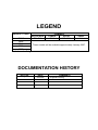
LEGEND
PRODUCT CODE
*B245
B268
B269
B276
B277
*Latin America Only
GESTETNER
DSm715
COMPANY
LANIER
RICOH
LD315
MP 1500
SAVIN
N/A
These models will be available approximately January 2007.
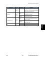
DOCUMENTATION HISTORY
REV. NO.
*
DATE
06/2006
COMMENTS
Original Printing
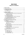
B245/B268/B269/B276/B277
TABLE OF CONTENTS
INSTALLATION
1. INSTALLATION ....................................................................... 1-1
1.1 INSTALLATION REQUIREMENTS .......................................................1-1
1.1.1 ENVIRONMENT ...........................................................................1-1
1.1.2 MACHINE LEVEL.........................................................................1-2
1.1.3 MINIMUM SPACE REQUIREMENTS ..........................................1-2
1.1.4 POWER REQUIREMENTS ..........................................................1-2
1.2 COPIER INSTALLATION ......................................................................1-4
1.2.1 POWER SOCKETS FOR PERIPHERALS ...................................1-4
1.2.2 ACCESSORY CHECK .................................................................1-4
1.2.3 INSTALLATION PROCEDURE ....................................................1-5
1.3 PLATEN COVER INSTALLATION ........................................................1-9
1.3.1 ACCESSORY CHECK .................................................................1-9
1.3.2 INSTALLATION PROCEDURE ....................................................1-9
1.4 ARDF INSTALLATION ........................................................................1-10
1.4.1 ACCESSORY CHECK ...............................................................1-10
1.4.2 INSTALLATION PROCEDURE ..................................................1-11
1.5 ADF INSTALLATION ...........................................................................1-14
1.5.1 ACCESSORY CHECK ...............................................................1-14
1.5.2 INSTALLATION PROCEDURE ..................................................1-15
1.6 TWO-TRAY PAPER TRAY UNIT INSTALLATION ..............................1-18
1.6.1 ACCESSORY CHECK ...............................................................1-18
1.6.2 INSTALLATION PROCEDURE ..................................................1-18
1.7 ONE-TRAY PAPER TRAY UNIT INSTALLATION...............................1-23
1.7.1 ACCESSORY CHECK ...............................................................1-23
1.7.2 INSTALLATION PROCEDURE ..................................................1-23
1.8 ONE-BIN TRAY INSTALLATION.........................................................1-27
1.8.1 ACCESSORY CHECK ...............................................................1-27
1.8.2 INSTALLATION PROCEDURE ..................................................1-27
1.9 ANTI-CONDENSATION HEATER INSTALLATION ............................1-30
1.10 TRAY HEATERS .............................................................................1-31
1.10.1 UPPER TRAY HEATER ...........................................................1-31
1.10.2 LOWER TRAY HEATER (TWO-TRAY MODEL ONLY) ...........1-33
1.10.3 TRAY HEATERS FOR THE OPTIONAL PAPER FEED UNITS1-34
1.11 KEY COUNTER INSTALLATION ....................................................1-38
1.12 GDI EXPANSION ............................................................................1-41
1.12.1 ACCESSORY CHECK .............................................................1-41
1.12.2 INSTALLING EXPANSION COMPONENT ..............................1-41
1.13 INSTALLING PANELS AND KEYS .................................................1-43
SM
i
B245/B268/B269/B276/B277
PREVENTIVE MAINTENANCE
2. PREVENTIVE MAINTENANCE ............................................... 2-1
2.1 PM TABLES ..........................................................................................2-1
2.2 HOW TO RESET THE PM COUNTER..................................................2-4
REPLACEMENT AND ADJUSTMENT
3. REPLACEMENT AND ADJUSTMENT .................................... 3-1
3.1 GENERAL CAUTIONS ..........................................................................3-1
3.1.1 PCU (PHOTOCONDUCTOR UNIT) .............................................3-1
3.1.2 TRANSFER ROLLER...................................................................3-1
3.1.3 SCANNER UNIT...........................................................................3-1
3.1.4 LASER UNIT ................................................................................3-2
3.1.5 FUSING UNIT ..............................................................................3-2
3.1.6 PAPER FEED...............................................................................3-2
3.2 SPECIAL TOOLS AND LUBRICANTS ..................................................3-3
3.3 EXTERIOR COVERS & OPERATION PANEL ......................................3-4
3.3.1 REAR COVER..............................................................................3-4
3.3.2 REAR LOWER COVER (TWO-TRAY MODELS ONLY) ..............3-4
3.3.3 COPY TRAY.................................................................................3-5
3.3.4 UPPER COVERS .........................................................................3-5
3.3.5 LEFT COVER ...............................................................................3-6
3.3.6 FRONT COVER ...........................................................................3-6
3.3.7 FRONT RIGHT COVER ...............................................................3-7
3.3.8 RIGHT REAR COVER..................................................................3-7
3.3.9 RIGHT DOOR (DUPLEX UNIT (B269/B277)) ..............................3-8
3.3.10 BY-PASS TRAY .........................................................................3-8
3.3.11 LEFT LOWER COVER (TWO-TRAY MODELS ONLY)..............3-9
3.3.12 RIGHT LOWER COVER (TWO-TRAY MODELS ONLY) ...........3-9
3.3.13 PLATEN COVER SENSOR......................................................3-10
3.4 SCANNER UNIT..................................................................................3-11
3.4.1 EXPOSURE GLASS/DF EXPOSURE GLASS ...........................3-11
3.4.2 LENS BLOCK .............................................................................3-11
3.4.3 LAMP STABILIZER BOARD AND EXPOSURE LAMP ..............3-12
3.4.4 ORIGINAL WIDTH/LENGTH SENSOR ......................................3-13
3.4.5 SCANNER MOTOR....................................................................3-15
3.4.6 SCANNER HOME POSITION SENSOR ....................................3-16
3.4.7 ADJUSTING SCANNER POSITIONS ........................................3-17
3.5 LASER UNIT .......................................................................................3-21
3.5.1 LOCATION OF CAUTION DECAL .............................................3-21
3.5.2 TONER SHIELD GLASS ............................................................3-21
3.5.3 LASER UNIT ..............................................................................3-22
3.5.4 LD UNIT .....................................................................................3-23
3.5.5 POLYGONAL MIRROR MOTOR................................................3-23
3.5.6 LASER UNIT ALIGNMENT ADJUSTMENT ...............................3-24
3.6 PCU SECTION ....................................................................................3-26
B245/B268/B269/B276/B277
ii
SM
3.6.1 PCU............................................................................................3-26
3.6.2 PICK-OFF PAWLS AND TONER DENSITY SENSOR...............3-27
3.6.3 OPC DRUM ................................................................................3-28
3.6.4 CHARGE ROLLER AND CLEANING BRUSH ...........................3-29
3.6.5 CLEANING BLADE ....................................................................3-29
3.6.6 DEVELOPER .............................................................................3-30
3.6.7 AFTER REPLACEMENT OR ADJUSTMENT ............................3-31
3.7 TONER SUPPLY MOTOR...................................................................3-32
3.8 PAPER FEED SECTION .....................................................................3-33
3.8.1 PAPER FEED ROLLER .............................................................3-33
3.8.2 FRICTION PAD ..........................................................................3-33
3.8.3 PAPER END SENSOR...............................................................3-34
3.8.4 EXIT SENSOR ...........................................................................3-34
3.8.5 BY-PASS FEED ROLLER AND PAPER END SENSOR............3-35
3.8.6 REGISTRATION ROLLER .........................................................3-36
3.8.7 BY-PASS PAPER SIZE SWITCH...............................................3-37
3.8.8 REGISTRATION CLUTCH .........................................................3-38
3.8.9 REGISTRATION SENSOR ........................................................3-38
3.8.10 UPPER PAPER FEED CLUTCH AND BY-PASS FEED CLUTCH3-39
3.8.11 RELAY CLUTCH ......................................................................3-39
3.8.12 RELAY SENSOR......................................................................3-40
3.8.13 LOWER PAPER FEED CLUTCH (TWO-TRAY MODELS ONLY)3-40
3.8.14 VERTICAL TRANSPORT SENSOR (TWO-TRAY MODELS ONLY)3-41
3.8.15 PAPER SIZE SWITCH .............................................................3-41
3.9 IMAGE TRANSFER.............................................................................3-42
3.9.1 IMAGE TRANSFER ROLLER ....................................................3-42
3.9.2 IMAGE DENSITY SENSOR .......................................................3-42
3.10 FUSING ...........................................................................................3-44
3.10.1 FUSING UNIT ..........................................................................3-44
3.10.2 THERMISTOR..........................................................................3-44
3.10.3 FUSING LAMPS.......................................................................3-45
3.10.4 HOT ROLLER STRIPPER PAWLS ..........................................3-46
3.10.5 HOT ROLLER ..........................................................................3-46
3.10.6 THERMOSTAT.........................................................................3-47
3.10.7 PRESSURE ROLLER AND BUSHINGS ..................................3-47
3.10.8 NIP BAND WIDTH ADJUSTMENT...........................................3-48
3.10.9 CLEANING ROLLER................................................................3-49
3.11 DUPLEX UNIT (DUPLEX MODELS B269/B277 ONLY)..................3-50
3.11.1 DUPLEX EXIT SENSOR ..........................................................3-50
3.11.2 DUPLEX ENTRANCE SENSOR ..............................................3-50
3.11.3 DUPLEX INVERTER SENSOR ................................................3-51
3.11.4 DUPLEX TRANSPORT MOTOR..............................................3-51
3.11.5 DUPLEX INVERTER MOTOR..................................................3-52
3.11.6 DUPLEX CONTROL BOARD ...................................................3-52
3.12 OTHER REPLACEMENTS..............................................................3-53
3.12.1 QUENCHING LAMP.................................................................3-53
3.12.2 HIGH-VOLTAGE POWER SUPPLY BOARD ...........................3-53
3.12.3 BICU (BASE-ENGINE IMAGE CONTROL UNIT).....................3-54
3.12.4 MAIN MOTOR ..........................................................................3-54
SM
iii
B245/B268/B269/B276/B277
3.12.5 REAR EXHAUST FAN (B269/B277 ONLY)..............................3-55
3.12.6 LEFT EXHAUST FAN...............................................................3-55
3.12.7 PSU (POWER SUPPLY UNIT).................................................3-56
3.12.8 GEARBOX................................................................................3-57
3.13 COPY ADJUSTMENTS PRINTING/SCANNING .............................3-60
3.13.1 PRINTING ................................................................................3-60
3.13.2 SCANNING ..............................................................................3-62
3.13.3 ADF IMAGE ADJUSTMENT.....................................................3-64
TROUBLESHOOTING
4. TROUBLESHOOTING ............................................................. 4-1
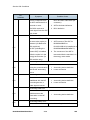
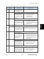
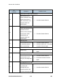
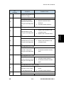
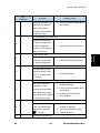
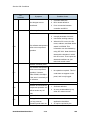
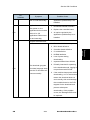
4.1 SERVICE CALL CONDITIONS .............................................................4-1
4.1.1 SUMMARY ...................................................................................4-1
4.1.2 SC CODE DESCRIPTIONS .........................................................4-2
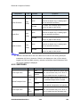
4.2 ELECTRICAL COMPONENT DEFECTS.............................................4-18
4.2.1 SENSORS..................................................................................4-18
4.2.2 SWITCHES ................................................................................4-20
4.3 BLOWN FUSE CONDITIONS .............................................................4-22
4.4 LED DISPLAY .....................................................................................4-23
4.4.1 BICU...........................................................................................4-23
SERVICE TABLES
5. SERVICE TABLES .................................................................. 5-1
5.1 SERVICE PROGRAM MODE................................................................5-1
5.1.1 HOW TO ENTER THE SP MODE ................................................5-1
5.2 SP MODE TABLES ...............................................................................5-3
5.2.1 SP1-XXX (FEED) .........................................................................5-3
5.2.2 SP2-XXX (DRUM) ........................................................................5-6
5.2.3 SP4-XXX (SCANNER) ...............................................................5-12
5.2.4 SP5-XXX (MODE) ......................................................................5-18
5.2.5 SP6-XXX (PERIPHERALS) ........................................................5-21
5.2.6 SP7-XXX (DATA LOG)...............................................................5-23
5.2.7 SP8-XXX (HISTORY) .................................................................5-27
5.2.8 SP9-XXX (ETC.).........................................................................5-32
5.3 USING SP MODES .............................................................................5-33
5.3.1 ADJUSTING REGISTRATION AND MAGNIFICATION .............5-33
5.3.2 ID SENSOR ERROR ANALYSIS (SP 2221) ..............................5-35
5.3.3 DISPLAY APS DATA (SP 4301 1)..............................................5-35
5.3.4 MEMORY CLEAR ......................................................................5-37
5.3.5 INPUT CHECK (SP 5803) ..........................................................5-39
5.3.6 OUTPUT CHECK (SP 5804) ......................................................5-42
5.3.7 SERIAL NUMBER INPUT (SP 5811) .........................................5-44
5.3.8 NVRAM DATA UPLOAD/DOWNLOAD (SP 5824/5825) ............5-44
5.3.9 FIRMWARE UPDATE PROCEDURE.........................................5-46
5.3.10 TEST PATTERN PRINT (SP 5902 1).......................................5-49
B245/B268/B269/B276/B277
iv
SM
5.3.11
5.3.12
5.3.13
5.3.14
PAPER JAM COUNTERS (SP 7504) .......................................5-51
SMC PRINT (SP 5990).............................................................5-52
ORIGINAL JAM HISTORY DISPLAY (SP 7508) ......................5-53
ADF APS SENSOR OUTPUT DISPLAY (SP 6901) .................5-53
DETAILED DESCRIPTIONS
6. DETAILED SECTION DESCRIPTIONS................................... 6-1
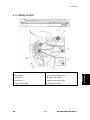
6.1 OVERVIEW ...........................................................................................6-1
6.1.1 COMPONENT LAYOUT...............................................................6-1
6.1.2 PAPER PATH...............................................................................6-2
6.1.3 DRIVE LAYOUT ...........................................................................6-3
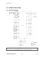
6.2 BOARD STRUCTURE...........................................................................6-4
6.2.1 BLOCK DIAGRAM........................................................................6-4
6.2.2 BICU (BASE ENGINE AND IMAGE CONTROL UNIT) ................6-5
6.2.3 SBU (SENSOR BOARD UNIT) ....................................................6-5
6.3 COPY PROCESS OVERVIEW..............................................................6-6
6.4 SCANNING............................................................................................6-8
6.4.1 OVERVIEW ..................................................................................6-8
6.4.2 SCANNER DRIVE ........................................................................6-9
6.4.3 ORIGINAL SIZE DETECTION IN PLATEN MODE.....................6-10
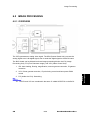
6.5 IMAGE PROCESSING ........................................................................6-13
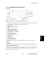
6.5.1 OVERVIEW ................................................................................6-13
6.5.2 SBU (SENSOR BOARD UNIT) ..................................................6-14
6.5.3 IPU (IMAGE PROCESSING UNIT) ............................................6-15
6.5.4 VIDEO CONTROL UNIT (VCU)..................................................6-25
6.6 LASER EXPOSURE ............................................................................6-27
6.6.1 OVERVIEW ................................................................................6-27
6.6.2 AUTO POWER CONTROL (APC)..............................................6-28
6.6.3 LD SAFETY SWITCH.................................................................6-29
6.7 PHOTOCONDUCTOR UNIT (PCU) ....................................................6-30
6.7.1 OVERVIEW ................................................................................6-30
6.7.2 DRIVE ........................................................................................6-31
6.8 DRUM CHARGE .................................................................................6-32
6.8.1 OVERVIEW ................................................................................6-32
6.8.2 CHARGE ROLLER VOLTAGE CORRECTION ..........................6-33
6.8.3 ID SENSOR PATTERN PRODUCTION TIMING........................6-34
6.8.4 DRUM CHARGE ROLLER CLEANING......................................6-34
6.9 DEVELOPMENT .................................................................................6-35
6.9.1 OVERVIEW ................................................................................6-35
6.9.2 DRIVE ........................................................................................6-36
6.9.3 DEVELOPER MIXING................................................................6-36
6.9.4 DEVELOPMENT BIAS ...............................................................6-37
6.9.5 TONER SUPPLY........................................................................6-38
6.9.6 TONER SUPPLY MECHANISM .................................................6-39
6.9.7 TONER DENSITY CONTROL ....................................................6-39
6.9.8 TONER SUPPLY IN ABNORMAL SENSOR CONDITIONS.......6-43
6.9.9 TONER NEAR END/END DETECTION AND RECOVERY........6-44
SM
v
B245/B268/B269/B276/B277
6.10 DRUM CLEANING AND TONER RECYCLING...............................6-45
6.10.1 DRUM CLEANING ...................................................................6-45
6.10.2 TONER RECYCLING ...............................................................6-46
6.11 PAPER FEED..................................................................................6-47
6.11.1 OVERVIEW ..............................................................................6-47
6.11.2 PAPER FEED DRIVE MECHANISM ........................................6-48
6.11.3 PAPER FEED AND SEPARATION MECHANISM ...................6-48
6.11.4 PAPER LIFT MECHANISM ......................................................6-49
6.11.5 PAPER END DETECTION .......................................................6-49
6.11.6 PAPER SIZE DETECTION.......................................................6-50
6.11.7 SIDE FENCES .........................................................................6-52
6.11.8 PAPER REGISTRATION .........................................................6-52
6.12 IMAGE TRANSFER AND PAPER SEPARATION ...........................6-54
6.12.1 OVERVIEW ..............................................................................6-54
6.12.2 IMAGE TRANSFER CURRENT TIMING..................................6-55
6.12.3 TRANSFER ROLLER CLEANING............................................6-56
6.12.4 PAPER SEPARATION MECHANISM ......................................6-56
6.13 IMAGE FUSING AND PAPER EXIT ................................................6-58
6.13.1 OVERVIEW ..............................................................................6-58
6.13.2 FUSING UNIT DRIVE AND RELEASE MECHANISM..............6-59
6.13.3 FUSING ENTRANCE GUIDE SHIFT........................................6-60
6.13.4 PRESSURE ROLLER ..............................................................6-61
6.13.5 FUSING TEMPERATURE CONTROL .....................................6-61
6.13.6 OVERHEAT PROTECTION .....................................................6-63
6.14 DUPLEX UNIT.................................................................................6-65
6.14.1 OVERALL.................................................................................6-65
6.14.2 DRIVE MECHANISM................................................................6-66
6.14.3 BASIC OPERATION.................................................................6-66
6.14.4 FEED IN AND EXIT MECHANISM ...........................................6-69
6.15 ENERGY SAVER MODES OF BASIC MACHINES.........................6-70
6.15.1 OVERVIEW ..............................................................................6-70
6.15.2 AOF ..........................................................................................6-71
6.15.3 TIMERS....................................................................................6-71
6.15.4 RECOVERY .............................................................................6-71
6.16 ENERGY SAVER MODES OF GDI MACHINES .............................6-72
6.16.1 OVERVIEW ..............................................................................6-72
6.16.2 AOF ..........................................................................................6-73
6.16.3 TIMERS....................................................................................6-73
6.16.4 RECOVERY .............................................................................6-73
SPECIFICATIONS
7. SPECIFICATIONS ................................................................... 7-1
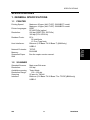
7.1 GENERAL SPECIFICATIONS...............................................................7-1
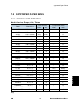
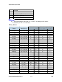
7.2 SUPPORTED PAPER SIZES................................................................7-5
7.2.1 ORIGINAL SIZE DETECTION......................................................7-5
7.2.2 PAPER FEED AND EXIT .............................................................7-7
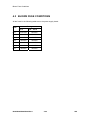
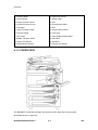
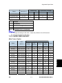
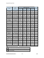
7.3 MACHINE CONFIGURATION .............................................................7-10
B245/B268/B269/B276/B277
vi
SM
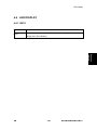
7.4 OPTIONAL EQUIPMENT ....................................................................7-12
7.4.1 ARDF..........................................................................................7-12
7.4.2 ADF ............................................................................................7-12
7.4.3 ONE-TRAY PAPER TRAY UNIT ................................................7-13
7.4.4 TWO-TRAY PAPER TRAY UNIT ...............................................7-13
7.4.5 ONE-BIN TRAY .........................................................................7-14
DOCUMENT FEEDER (B813)/ARDF (B814)
SEE SECTION B813/B814 FOR DETAILED TABLE OF CONTENTS
DDST UNIT (B865/B866)
SEE SECTION B865/B866 FOR DETAILED TABLE OF CONTENTS
SM
vii
B245/B268/B269/B276/B277
Read This First
Safety Notices and Symbols & Abbreviations
Important Safety Notices
Prevention of Physical Injury
1. Before disassembling or assembling parts of the copier and peripherals,
make sure that the power cord is unplugged.
2. The wall outlet should be near the copier and easily accessible.
3. Note that some components of the copier and the paper tray unit are
supplied with electrical voltage even if the main power switch is turned off.
4. If a job has started before the copier completes the warm-up or initializing
period, keep hands away from the mechanical and electrical components
because the starts making copies as soon as the warm-up period is
completed.
5. The inside and the metal parts of the fusing unit become extremely hot
while the copier is operating. Be careful to avoid touching those
components with your bare hands.
Health Safety Conditions
Toner and developer are non-toxic, but if you get either of them in your eyes by accident, it
may cause temporary eye discomfort. Try to remove with eye drops or flush with water as
first aid. If unsuccessful, get medical attention.
Observance of Electrical Safety Standards
The copier and its peripherals must be installed and maintained by a customer service
representative who has completed the training course on those models.
Safety and Ecological Notes for Disposal
1. Do not incinerate toner bottles or used toner. Toner dust may ignite
suddenly when exposed to an open flame.
2. Dispose of used toner, developer, and organic photoconductors in
accordance with local regulations. (These are non-toxic supplies.)
3. Dispose of replaced parts in accordance with local regulations.
Laser Safety
The Center for Devices and Radiological Health (CDRH) prohibits the repair of laser-based
optical units in the field. The optical housing unit can only be repaired in a factory or at a
location with the requisite equipment. The laser subsystem is replaceable in the field by a
qualified Customer Engineer. The laser chassis is not repairable in the field. Customer
Engineers are therefore directed to return all chassis and laser subsystems to the factory
or service depot when replacement of the optical subsystem is required.
-1. Use of controls, or adjustment, or performance of procedures other than
those specified in this manual may result in hazardous radiation exposure.
WARNING FOR LASER UNIT
WARNING: Turn off the main switch before attempting any of the procedures in the
Laser Unit section. Laser beams can seriously damage your eyes.
CAUTION MARKING:
Symbols and Abbreviations
This manual uses several symbols and abbreviations. The meaning of those symbols and
abbreviations are as follows:
See or Refer to
Clip ring
Screw
Connector
SEF
Short Edge Feed
LEF
Long Edge Feed
REPLACEMENT AND ADJUSTMENT
TROUBLESHOOTING
TAB
POSITION 1
TAB
POSITION 5
DETAILED DESCRIPTIONS
TAB
POSITION 8
SPECIFICATIONS
TAB
POSITION 7
SERVICE TABLES
TAB
POSITION 6
DDST UNIT B865/B866
TAB
POSITION 2
PREVENTIVE MAINTENANCE
TAB
POSITION 3
DOCUMENT FEEDER B813/ARDF B814
TAB
POSITION 4
INSTALLATION
INSTALLATION
Installation
Installation Requirements
1. INSTALLATION
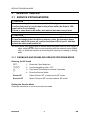
1.1 INSTALLATION REQUIREMENTS
-21. Before installing options, please do the following:
-6850556.
If there is a printer option in the machine, print out all data in the printer
buffer.
-6850555.
Turn off the main switch and disconnect the power cord, the telephone
line, and the network cable.
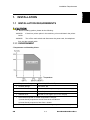
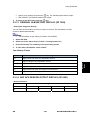
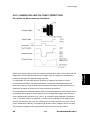
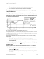
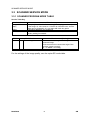
1.1.1 ENVIRONMENT
–Temperature and Humidity Chart–
1. Temperature Range:
10C to 32C (50F to 89.6F)
1. Humidity Range:
15% to 80% RH
1. Ambient Illumination:
Less than 1,500 lux (do not expose to direct sunlight)
1. Ventilation:
3 times/hr/person or more
1. Ambient Dust:
Less than 0.075 mg/m3 (2.0 x 10⁻⁶ oz/yd3)
1. Avoid areas exposed to sudden temperature changes:
1) Areas directly exposed to cool air from an air conditioner.
2) Areas directly exposed to heat from a heater.
1. Do not place the machine in areas where it can get exposed to corrosive gases.
SM
1-1
B245/B268/B269/B276/B277
Installation Requirements
1. Do not install the machine at any location over 2,000 m (6,500 ft.) above sea level.
1. Place the machine on a strong and level base. (Inclination on any side should be no
more than 5 mm.)
1. Do not place the machine where it is subjected to strong vibrations.
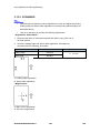
1.1.2 MACHINE LEVEL
Front to back:
Within 5 mm (0.2") of level
Right to left:
Within 5 mm (0.2") of level
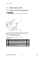
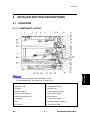
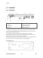
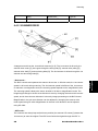
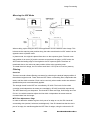
1.1.3 MINIMUM SPACE REQUIREMENTS
Place the copier near the power source, providing clearance as shown:
A (front): 750 mm (30")
B (left): 150 mm (6")
C (rear): 50 mm (2")
D (right): 250 mm (10")
The recommended 750 mm front space is sufficient to allow the paper tray to be pulled out.
Additional front space is required to allow operators to stand at the front of the machine.
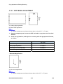
1.1.4 POWER REQUIREMENTS
-6850556.
Make sure that the wall outlet is near the machine and easily accessible.
After. completing installation, make sure the plug fits firmly into the outlet.
-6850555.
Avoid multi-wiring.
-6850554.
Be sure to ground the machine
Input voltage:
North and South America, Taiwan: 110 – 120 V, 60 Hz, 12 A
B245/B268/B269/B276/B277
1-2
SM
Europe, Asia:
SM
Installation
Installation Requirements
220 – 240 V, 50/60 Hz, 7 A
1-3
B245/B268/B269/B276/B277
Copier Installation
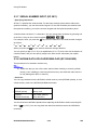
1.2 COPIER INSTALLATION
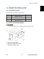
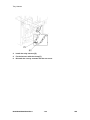
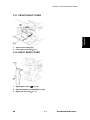
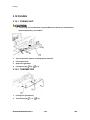
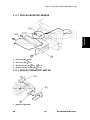
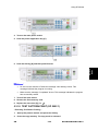
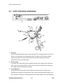
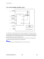
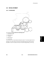
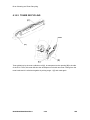
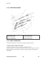
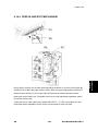
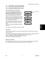
1.2.1 POWER SOCKETS FOR PERIPHERALS
-21. Make sure to plug the cables into the correct sockets.
[A]: Socket for ADF/ARDF (Rated voltage output max. DC24 V)
[B]: Socket for paper tray unit (Rated voltage output max. DC24 V)
1.2.2 ACCESSORY CHECK
Check that you have the accessories in this list.
Basic Machines
No.
Description
Q’ty
1
NECR-English /Multi-language (-17, -27,-19, -29)
1
2
EU Safety Sheet (-27, -22,-24, -26)
1
3
Laser Decal (-27, -22,-24, -26, -19, -28, -29)
1
4
Model Name Plate (-22,-29)
1
B245/B268/B269/B276/B277
1-4
SM
Installation
Copier Installation
GDI Machines
No.
Description
Q’ty
1
NECR-English /Multi-language (-19, -29)
1
2
Laser Decal (-19, -29)
1
3
Model Name Plate (-19, -29)
1
4
Operating Instructions (-19, -29)
1
5
General Setting Guide (-19, -29)
1
6
Copy Reference (-19, -29)
1
7
Printer/Scanner Reference (-19, -29)
1
8
Network Reference (-19, -29)
1
9
Quick Guide Copy Edition (-19, -29)
1
10 Quick Guide Printer/Scanner Edition (-19, -29)
1
11 Manual for this machine (-19, -29)
1
12 Safety Information (-19, -29)
1
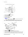
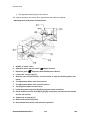
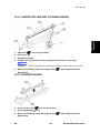
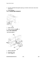
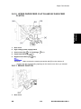
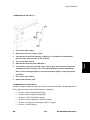
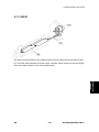
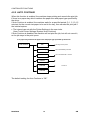
1.2.3 INSTALLATION PROCEDURE
-21. Unplug the machine power cord before starting the following procedure.
1.
SM
Remove filament tape and other padding.
1-5
B245/B268/B269/B276/B277
Copier Installation
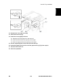
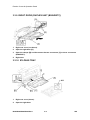
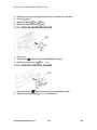
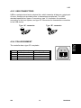
2.
Open the front door and remove the toner bottle holder [A]
3.
Open the right door [B], and remove the PCU (photoconductor unit) [C].
4.
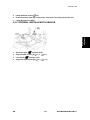
Separate the PCU into the upper part and the lower part (
5.
Put a sheet of paper on a level surface and place the upper part on it.
B245/B268/B269/B276/B277
1-6
x 5).
SM
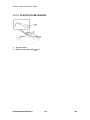
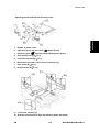
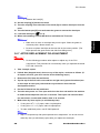
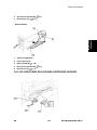
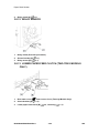
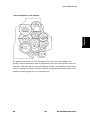
-6850556.
6.
This prevents foreign material from getting on the sleeve rollers
Distribute a pack of developer [D] to all openings equally.
-6850556.
Do not spill the developer on the gears [E]. If you have spilled it, remove
the developer by using a magnet or magnetized screwdriver.
-6850555.
Do not turn the gear [E] too much. The developer may spill.
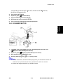
7.
Reassemble the PCU and reinstall it.
8.
Shake the toner bottle [F] several times. (Do not remove the bottle cap [G] before
you shake the bottle.)
9.
Remove the bottle cap [G] and install the bottle on the holder. (Do not touch the
inner cap [H].)
10. Set the holder (with the toner bottle) in the machine.
SM
1-7
B245/B268/B269/B276/B277
Installation
Copier Installation
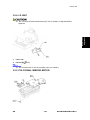
Copier Installation
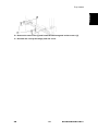
11. Pull out the paper tray [I] and turn the paper size dial to the appropriate size.
Adjust the positions of the end and side guides.
-6850556.
To move the side guides, release the green lock on the rear side guide.
12. Install the optional ARDF, ADF, or platen cover.
13. Plug in the main power cord and turn on the main switch.
14. Activate the SP mode and execute "Devlpr Initialize" (SP 2214 1).
15. Wait until the message "Completed" shows (about 45 seconds).
16. Activate the User Tools and select the menu "Language."
17. Specify a language. This language is used for the operation panel.
18. Load the paper in the paper tray and make a full size copy, and make sure the
side-to-side and leading edge registrations are correct.
B245/B268/B269/B276/B277
1-8
SM
Installation
Platen Cover Installation
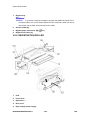
1.3 PLATEN COVER INSTALLATION
1.3.1 ACCESSORY CHECK
Check that you have the accessories indicated below.
No.
Description
Q’ty
1
Stepped Screw
2
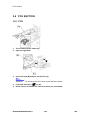
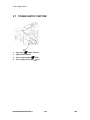
1.3.2 INSTALLATION PROCEDURE
-21. Unplug the machine power cord before starting the following procedure.
Install the platen cover (
SM
x 2).
1-9
B245/B268/B269/B276/B277
ARDF Installation
1.4 ARDF INSTALLATION
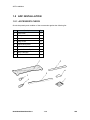
1.4.1 ACCESSORY CHECK
Check the quantity and condition of the accessories against the following list.
No.
Description
Q’ty
1
Scale Guide
1
2
DF Exposure Glass
1
3
Stud Screw
2
4
Knob Screw
2
5
Original Size Decal
2
6
Screwdriver Tool
1
7
Attention Decal—Top Cover
1
8
Stamp Cartridge
1
9
Installation Procedure
1
B245/B268/B269/B276/B277
1-10
SM
Installation
ARDF Installation
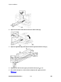
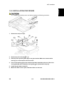
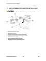
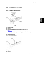
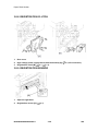
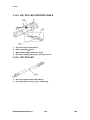
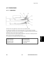
1.4.2 INSTALLATION PROCEDURE
-21. Unplug the copier power cord before starting the following procedure.
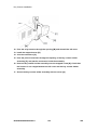
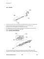
1.
Remove the strips of tape.
2.
Remove the left scale [A] (
3.
Place the DF exposure glass [B] on the glass holder. Make sure that the white
x 2).
mark [C] is on the bottom at the front end.
4.
Peel off the backing [D] of the double-sided tape attached to the rear side of the
scale guide [E], then install the scale guide (
x 2 [removed in step 2]).
5.
Install the two stud screws [F].
6.
Mount the ARDF on the copier, and then slide it to the front.
SM
1-11
B245/B268/B269/B276/B277
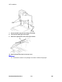
ARDF Installation
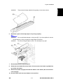
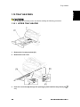
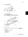
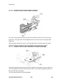
7.
Secure the ARDF unit with the knob screws [G].
8.
Connect the cable [H] to the copier.
9.
Attach the appropriate original size decal [I] as shown.
10. Attach an attention decal to the top cover.
-21. The attention decals in the package are written in different languages.
B245/B268/B269/B276/B277
1-12
SM
Installation
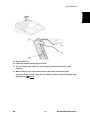
ARDF Installation
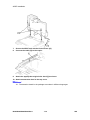
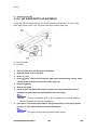
11. Open the ARDF [J].
12. Install the stamp cartridge [K] to the ARDF.
13. Make a full size copy, and check that the side-to-side and leading edge
registrations are correct. If they are not, adjust the side-to-side and leading edge
registrations. (
SM
p.3-64)
1-13
B245/B268/B269/B276/B277
ADF Installation
1.5 ADF INSTALLATION
1.5.1 ACCESSORY CHECK
Check the quantity and condition of the accessories against the following list.
No.
Description
Q’ty
1
Scale Guide
1
2
DF Exposure Glass
1
3
Stud Screw
2
4
Fixing Screw
2
5
Original Size Decal
2
6
Screwdriver Tool
1
7
Attention Decal—Top Cover
1
8
Stamp Cartridge
1
9
Installation Procedure
1
B245/B268/B269/B276/B277
1-14
SM
Installation
ADF Installation
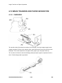
1.5.2 INSTALLATION PROCEDURE
-21. Unplug the machine power cord before starting the following procedure.
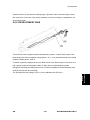
1.
Remove the strips of tape.
2.
Remove the left scale [A] (
3.
Place the DF exposure glass [B] on the glass holder. Make sure that the white
x 2).
mark [C] is on the bottom at the front end.
4.
Peel off the backing [D] of the double-sided tape attached to the rear side of the
scale guide [E], then install the scale guide (
x 2 [removed in step 2]).
5.
Install the two stud screws [F].
6.
Mount the ADF on the copier, and then slide it to the front.
SM
1-15
B245/B268/B269/B276/B277
ADF Installation
7.
Secure the ADF unit with the fixing screws [G].
8.
Connect the cable [H] to the copier.
9.
Attach the appropriate scale decal [I] as shown.
10. Attach an attention decal to the top cover.
-21. The attention decals in the package are written in different languages.
B245/B268/B269/B276/B277
1-16
SM
Installation
ADF Installation
11. Open the ADF [J].
12. Install the stamp cartridge [K] to the ADF
13. Turn the main power switch on. Then check if the document feeder works
properly.
14. Make a full size copy, and check that the side-to-side and leading edge
registrations are correct. If they are not, adjust the side-to-side and leading edge
registrations. (
SM
p.114).
1-17
B245/B268/B269/B276/B277
Two-tray Paper Tray Unit Installation
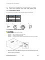
1.6 TWO-TRAY PAPER TRAY UNIT INSTALLATION
1.6.1 ACCESSORY CHECK
Check the quantity and condition of the accessories against the following list.
No.
Description
Q’ty
1
Screw – M4x10
10
2
Unit Holder
3
Adjuster
1
4
Unit Holder
2
2 x 2 pieces
1.6.2 INSTALLATION PROCEDURE
-21. If the optional printer unit is installed:
1.
-6850556.
Print out all data in the printer buffer.
-6850555.
Disconnect the network cable.
-6850554.
Unplug the machine power cord before starting the following procedure.
Remove the strips of tape. Make sure that you have removed all the strips of tape
and all the pieces of cardboard.
B245/B268/B269/B276/B277
1-18
SM
-6850556.
After removing the tape that secures the peripheral components and
cardboard to the paper tray, make sure that there is no tape and/or tape reside
remaining on the tray.
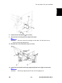
2.
Attach the adjuster [A] to the base plate as shown.
-21. This step is not necessary if a cabinet is installed.
3.
SM
Remove the cover [B] (1 rivet).
1-19
B245/B268/B269/B276/B277
Installation
Two-tray Paper Tray Unit Installation
Two-tray Paper Tray Unit Installation
4.
Set the copier on the paper tray unit.
-6850556.
Before placing the copier on the paper tray unit, make sure that the
harness [C] is securely routed. The paper tray unit does not function properly if the
harness is damaged.
5.
One-tray copier model (B268/B276): Remove the 1st tray cassette [D].
Two-tray copier models (B269/B277): Remove the 2nd tray cassette [D].
6.
Install the two screws [E].
7.
Reinstall the tray cassette.
B245/B268/B269/B276/B277
1-20
SM
Installation
Two-tray Paper Tray Unit Installation
8.
Install the two brackets [F] (
9.
Connect the connecting harness [G] to the copier.
-6850556.
x 1 (each))
There are cutouts for the plugs on both sides. The left side has one
cutout, and the right side has two.
10. Reinstall the cover removed in step 3 (1 rivet).
11. Install the four brackets with long supports [H] and covers [I](2 screws each).
-6850556.
SM
These long supports prevent the unit from tipping over.
1-21
B245/B268/B269/B276/B277
Two-tray Paper Tray Unit Installation
12. Rotate the adjuster (installed at step 2) to fix the machine in place.
-6850556.
If a cabinet is installed, this step is unnecessary.
13. Load the paper in the paper trays and make full size copies from each tray.
Check if the side-to-side and leading edge registrations are correct. If they are
not, adjust the registrations (
B245/B268/B269/B276/B277
Copy Adjustments Printing/Scanning).
1-22
SM
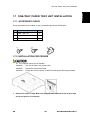
1.7 ONE-TRAY PAPER TRAY UNIT INSTALLATION
1.7.1 ACCESSORY CHECK
Check the quantity and condition of the accessories against the following list.
No.
1
Description
Q’ty
Screw – M4 x 10
2
2
Stepped Screw – M4 x 10
2
3
Unit Holder
2
1.7.2 INSTALLATION PROCEDURE
-21. If the optional printer unit is installed:
1.
-6850556.
Print out all data in the printer buffer.
-6850555.
Disconnect the network cable.
-6850554.
Unplug the machine power cord before starting the following procedure.
Remove the strips of tape. Make sure that you have removed all the strips of tape
and all the pieces of cardboard.
SM
1-23
B245/B268/B269/B276/B277
Installation
One-tray Paper Tray Unit Installation
One-tray Paper Tray Unit Installation
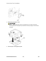
2.
Remove the cover [A] (1 rivet).
-6850556.
Before placing the copier on the paper tray unit, make sure that the
harness [B] is safe. The paper tray unit does not function properly if the harness is
damaged.
3.
Set the copier on the paper tray unit.
B245/B268/B269/B276/B277
1-24
SM
Installation
One-tray Paper Tray Unit Installation
4.
One-tray copier model (B268/B276): Remove the 1st tray cassette [C].
Two-tray copier models (B269/B277): Remove the 2nd tray cassette [C].
5.
Install the two screws [D].
6.
Reinstall the tray cassette.
SM
1-25
B245/B268/B269/B276/B277
One-tray Paper Tray Unit Installation
7.
Install the two brackets [E]. (1 stepped screw each).
8.
Connect the connecting harness [F] to the copier.
-6850556.
There are cutouts for the plugs on both sides. The left side has one
cutout, and the right side has two.
9.
Reinstall the cover removed in step 2.
10. Load the paper in the paper tray and make full size copies from tray. Check if the
side-to-side and leading edge registrations are correct. If they are not, adjust the
registrations (
p.3-60).
B245/B268/B269/B276/B277
1-26
SM
Installation
One-Bin Tray Installation
1.8 ONE-BIN TRAY INSTALLATION
1.8.1 ACCESSORY CHECK
Check the quantity and condition of the accessories.
No.
Description
Q’ty
1
Installation procedure
1
2
One-bin sorter
1
3
Exit tray
1
4
Tapping screw M3 x 6
1
1.8.2 INSTALLATION PROCEDURE
-21. Unplug the machine power cord before starting the following procedure.
1.
Remove the inverter tray [A].
2.
Remove the rail [B] (2 knob screws).
3.
Remove the cover [C] (1 rivet).
SM
1-27
B245/B268/B269/B276/B277
One-Bin Tray Installation
4.
Open the front cover [D].
5.
Remove the front right cover [E] (
6.
Disconnect the connector [F].
7.
Cut the front cover as shown, to make an opening [G] for the 1-bin tray.
8.
Install the 1-bin tray [H].
9.
Make sure the connectors [I] are connected firmly.
x 1).
10. Fasten the screw.
11. Connect the connector [J] that you removed in step 6.
-6850556.
Make sure that the connector is connected.
B245/B268/B269/B276/B277
1-28
SM
Installation
One-Bin Tray Installation
12. Reattach the front right cover [K].
13. Close the front cover [L].
14. Install the exit tray [M] as follows:
-21. Keep the front end higher than the rear end.
-20. Push the left hook into the opening in the copier.
-19. Push the right hook into the opening in the copier.
15. Pull the support [N] out of the left end of the exit tray.
16. Insert the support into the left end of the paper exit tray [O] (of the copier).
17. Turn the main switch on.
18. Check the operation.
SM
1-29
B245/B268/B269/B276/B277
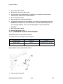
Anti-condensation Heater Installation
1.9 ANTI-CONDENSATION HEATER INSTALLATION
-21. Unplug the machine power cord before starting the following procedure.
1.
Remove the exposure glass.
2.
Remove the left cover.
3.
Pass the connector [A] through the opening [B].
4.
Install the anti-condensation heater [C], as shown.
5.
Join the connectors [A, D].
6.
Clamp the harness with the clamp [E].
7.
Reinstall the left cover and exposure glass.
B245/B268/B269/B276/B277
1-30
SM
Installation
Tray Heaters
1.10 TRAY HEATERS
-21. Unplug the machine power cord before starting the following procedure.
1.10.1 UPPER TRAY HEATER
1.
Remove the 1st tray cassette [A].
2.
Remove the rear cover.
3.
Pass the connector [B] through the opening [C] and install the tray heater [D] (
x 1).
SM
1-31
B245/B268/B269/B276/B277
Tray Heaters
4.
Install the relay harness [E].
5.
Fix the harness with the clamp [F].
6.
Reinstall the 1st tray cassette and the rear cover.
B245/B268/B269/B276/B277
1-32
SM
1.10.2 LOWER TRAY HEATER (TWO-TRAY MODEL ONLY)
1.
Remove the 2nd tray cassette [A].
2.
Remove the rear lower cover.
3.
B277/B269 only: Remove the DCB [B] with bracket (
4.
Pass the connector [C] through the opening [D] and install the tray heater [E] (
x 4,
x 3).
x 1).
5.
Join the connectors [F].
6.
Reinstall the 2nd tray cassette, DCB, and rear lower cover.
SM
1-33
B245/B268/B269/B276/B277
Installation
Tray Heaters
Tray Heaters
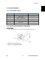
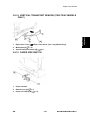
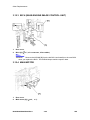
1.10.3 TRAY HEATERS FOR THE OPTIONAL PAPER FEED
UNITS
1.
Remove the rear cover [A] for the paper tray unit.
One-tray paper
feed unit:
Two-tray paper
feed unit:
2.
Two-tray unit only: Remove the cable guide [B].
B245/B268/B269/B276/B277
1-34
SM
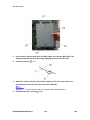
3.
Installation
Tray Heaters
Install the clamps [C].
One-tray paper
feed unit:
Two-tray paper
feed unit:
4.
Pass the connector [D] through the opening [E].
5.
Install the tray heater [F] (
SM
x 1).
1-35
B245/B268/B269/B276/B277
Tray Heaters
One-tray paper
feed unit:
Two-tray paper
feed unit:
6.
Clamp the cables [G], as shown.
7.
Join the connectors [H].
8.
Two-tray unit only: Reinstall the cable guide.
9.
One-tray copier model (B268/B276): Remove the 1st tray cassette.
Two-tray copier models (B269/B277): Remove the 2nd tray cassette.
B245/B268/B269/B276/B277
1-36
SM
Installation
Tray Heaters
10. Remove the two screws [I] and install the two hexagonal socket screws [J].
11. Reinstall the 1st tray/2nd tray(s) and rear cover.
SM
1-37
B245/B268/B269/B276/B277
Key Counter Installation
1.11 KEY COUNTER INSTALLATION
-21. Unplug the machine power cord before starting the following procedure.
1.
Remove the left cover.
2.
Remove the rear cover.
3.
Cut the cap [A] with nippers.
4.
Punch out the small hole [B] using a screwdriver.
5.
Hold the key counter plate nuts [C] on the inside of the key counter bracket [D]
and insert the key counter holder [E].
6.
Secure the key counter holder to the bracket (
7.
Install the key counter cover [F] (
B245/B268/B269/B276/B277
x 2).
x 2).
1-38
SM
Installation
Key Counter Installation
8.
Connect the connector [G] to CN126 on the BICU.
9.
Hold the harness with the clamps [H][I][J].
-6850556.
The relay harness is not included in the key counter bracket accessories.
10. Join the relay harness [K] with the connector [L].
11. Reinstall the rear cover.
SM
1-39
B245/B268/B269/B276/B277
Key Counter Installation
12. Pass the relay harness through the opening [M] and reinstall the left cover.
13. Install the stepped screw [N].
14. Join the connectors [O].
15. Pass the joined connectors through the opening of the key counter holder
assembly [P], and put the connectors inside the assembly.
16. Hook the key counter holder assembly onto the stepped screw [N]. Check that
the harness is not caught between the left cover and the key counter holder
assembly.
17. Secure the key counter holder assembly with the screw [Q].
B245/B268/B269/B276/B277
1-40
SM
Installation
GDI Expansion
1.12 GDI EXPANSION
1.12.1 ACCESSORY CHECK
No.
Description
Q’ty
1
Cover-CPS NA
1
2
Cover-CPS EU
1
3
Ferrite Core (B866 only)
1
4
Tapping Screw-M3X6
6
5
Sheet-EULA
1
6
Seal-Caution
1
7
Installation Procedure
1
1.12.2 INSTALLING EXPANSION COMPONENT
-21. Unplug the machine power cord before starting the following procedure.
x 6).
1.
Remove the rear cover [A] (
2.
Remove one screw [B] from the BICU.
SM
1-41
B245/B268/B269/B276/B277
GDI Expansion
3.
Connect the controller box [D] to the BICU. Make sure that the BICU [E] is not
damaged and that the three openings [F][G][H] hold the controller box.
4.
Fasten the screws (
5.
Attach the ferrite core [I] to the network cable [J]. The end of the ferrite core
x 7).
must be about 10 cm (4") from the end of the cable [K].
-6850556.
6.
This procedure is only for machines with the B866 option.
Re-attach the rear cover [A] (
B245/B268/B269/B276/B277
x 6).
1-42
SM
Installation
Installing Panels and Keys
1.13 INSTALLING PANELS AND KEYS
1.
Remove the dummy cover [A] from the operation panel.
2.
Install the printer/scanner panel [B] on the operation panel.
SM
1-43
B245/B268/B269/B276/B277
PREVENTIVE MAINTENANCE
PM Tables
2. PREVENTIVE MAINTENANCE
-21. After preventive maintenance work, reset the PM counter (SP 7804 1).
-20. PM intervals (60k, 80k, and 120K) indicate the number of prints.
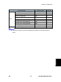
Key: AN: As necessary C: Clean R: Replace
L: Lubricate
I: Inspect
Optics
EM
60k
120k
AN
NOTE
Reflector
C
Optics cloth
1st mirror
C
C
Optics cloth
2nd mirror
C
C
Optics cloth
3rd mirror
C
C
Optics cloth
Scanner guide rails
C
Do not use alcohol.
Replace the platen sheet if
I
C
necessary.
Platen cover
Blower brush or alcohol
Exposure glass
C
C
Blower brush or alcohol
Toner shield glass
C
Blower brush
APS sensors
C
Blower brush
Drum Area
EM
60k
PCU
I
Drum
R
Developer
R
Charge roller
R
Cleaning brush (charge roller)
R
Cleaning blade (OPC drum)
R
Pick-off pawls (OPC drum)
R
Transfer roller
ID sensor
SM
120k
AN
NOTE
R
C
C
2-1
Blower brush
B245/B268/B269/B276/B277
Preventive
Maintenance
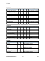
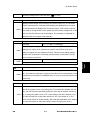
2.1 PM TABLES
PM Tables
Paper Feed
EM
60k
120k
AN
NOTE
Paper feed roller (each tray)
C
R
C
Clean with water or alcohol.
Friction pad (each tray)
C
R
C
Clean with water or alcohol.
Bottom-plate pad (each tray)
C
C
Clean with water or alcohol.
Paper feed roller (bypass tray)
C
C
Clean with water or alcohol.
Friction pad (bypass tray)
C
C
Clean with water or alcohol.
Bottom-plate pad (by-pass tray)
C
C
Clean with water or alcohol.
Registration rollers
C
C
Clean with water or alcohol.
Relay rollers
C
C
Clean with water or alcohol.
Paper feed guides
C
C
Clean with water or alcohol.
Paper-dust Mylar
C
C
Clean with water or alcohol.
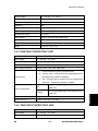
AN
NOTE
Fusing Unit
EM
60k
120k
Hot roller
R
Pressure roller
R
Pressure roller cleaning roller
R
Hot roller bushings
I
Pressure-roller bushing
R
Hot roller stripper pawls
R
Thermistor
C
Cleaning roller bushing
C
C
Dry cloth
C
Dry cloth
C
Dry cloth
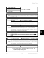
ADF/ARDF
80k
AN
Feed belt
R
C
Clean with water or alcohol.
Separation roller
R
C
Clean with water or alcohol.
Pick-up roller
R
C
Clean with water or alcohol.
Stamp
R
Replace when necessary.
White plate
C
Clean with water or alcohol.
DF exposure glass
C
Clean with water or alcohol.
Platen cover
C
Clean with water or alcohol.
B245/B268/B269/B276/B277
NOTE
2-2
SM
PM Tables
Paper Tray Unit
Paper feed rollers
120k
AN
NOTE
R
C
Dry or damp cloth
Bottom-plate pads
C
C
Dry cloth
Paper-feed guides
C
C
Clean with water or alcohol.
C
Dry or damp cloth
C
Dry cloth
Friction pads
R
Relay clutch (B384 only)
I
Feed clutches (B384 only)
I
Relay roller (B384 only)
C
SM
2-3
B245/B268/B269/B276/B277
Preventive
Maintenance
60k
How to Reset the PM Counter
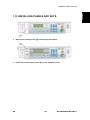
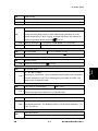
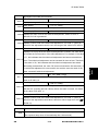
2.2 HOW TO RESET THE PM COUNTER
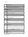
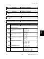
After preventive maintenance work, reset the PM counter (SP 7804 1) as follows:
1. Activate the SP mode (
p.5-1).
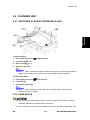
Select SP 7804 1 (Reset–PM Counter).
Press the OK key [A]. The message "Execute" shows.
Press the button [B] below the message "Execute."
The messages "Execute?" followed by "Cancel" and "Execute" show.
B245/B268/B269/B276/B277
2-4
SM
Preventive
Maintenance
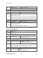
How to Reset the PM Counter
To reset the PM counter, press the button [C] below the message "Execute."
Wait until the message "Completed" shows.
Quit the SP mode.
SM
2-5
B245/B268/B269/B276/B277
REPLACEMENT AND ADJUSTMENT
General Cautions
3. REPLACEMENT AND ADJUSTMENT
3.1 GENERAL CAUTIONS
Do not turn off the main switch while any of the electrical components are active. Doing so
may result in damage to units (such as the PCU) as they are pulled out or replaced.
The PCU consists of the OPC drum, charge roller, development unit, and cleaning
components. Observe the following precautions when handling the PCU.
1. Never touch the drum surface with bare hands. If the drum surface is dirty
or if you have accidentally touched it, wipe it with a dry cloth, or clean it
with wet cotton and then wipe it dry with a cloth.
2. Never use alcohol to clean the drum. Alcohol will dissolve the drum
surface.
3. Store the PCU in a cool dry place.
4. Do not expose the drum to corrosive gases (ammonia, etc.).
5. Do not shake a used PCU, as this may cause toner and developer to spill
out.
6. Dispose of used PCU components in accordance with local regulations.
3.1.2 TRANSFER ROLLER
1. Never touch the surface of the transfer roller with bare hands.
2. Be careful not to scratch the transfer roller, as the surface is easily
damaged.
3.1.3 SCANNER UNIT
1. Use alcohol or glass cleaner to clean the exposure and scanning glass.
This will reduce the static charge on the glass.
2. Use a blower brush or a water-moistened cotton pad to clean the mirrors
and lenses.
3. Make sure to not bend or crease the exposure lamp’s ribbon cable.
4. Do not disassemble the lens unit. This will cause the lens and copy image
to get out of focus.
5. Do not turn any of the CCD positioning screws. This will put the CCD out
of position. The CCD position cannot be re-adjusted in the field.
SM
3-1
B245/B268/B269/B276/B277
Replacement
Adjustment
3.1.1 PCU (PHOTOCONDUCTOR UNIT)
General Cautions
3.1.4 LASER UNIT
1. Do not loosen or adjust the screws securing the LD drive board on the LD
unit. This will put the LD unit out of adjustment. The LD Unit position
cannot be re-adjusted properly in the field.
2. Do not adjust the variable resistors on the LD unit. These are adjusted at
the factory.
3. The polygonal mirror and F-theta lens are very sensitive to dust.
4. Do not touch the toner shield glass or the surface of the polygonal mirror
with bare hands.
3.1.5 FUSING UNIT
1. After installing the fusing thermistor, make sure that it is in contact with the
hot roller and that the roller can rotate freely.
2. Be careful to avoid damage to the hot roller stripper pawls and their
tension springs.
3. Do not touch the fusing lamp and rollers with bare hands.
4. Make sure that the fusing lamp is positioned correctly and that it does not
touch the inner surface of the hot roller.
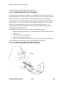
3.1.6 PAPER FEED
1. Do not touch the surface of the paper feed rollers.
2. To avoid misfeeds, the side and end fences in each paper tray must be
positioned correctly so as to align with the actual paper size.
•
You must run SP 2214 to initialize the TD sensor after you install a new PCU. After
starting initialization, be sure to wait for it to reach completion (wait for the motor to
stop) before you re-open the front cover or turn off the main switch.
•
If the optional tray heater or optics anti-condensation heater is installed, keep the
machine's power cord plugged in even while the main switch is off, to keep the
heater(s) energized.
B245/B268/B269/B276/B277
3-2
SM
Special Tools and Lubricants
3.2 SPECIAL TOOLS AND LUBRICANTS
SM
Description
Q’ty
A0069104
Scanner Positioning Pins (4 pins/set)
1 set
A2929500
Test Chart S5S (10 pcs/set)
1 set
VSSM9000
FLUKE 87 Digital Multimeter
1
N8036701
4MB Flash Memory Card
1
A2579300
Grease Barrierta S552R
1
52039502
Grease G-501
1
3-3
B245/B268/B269/B276/B277
Replacement
Adjustment
Part Number
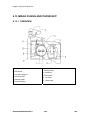
Exterior Covers & Operation Panel
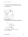
3.3 EXTERIOR COVERS & OPERATION PANEL
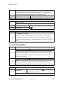
3.3.1 REAR COVER
1.
Unplug the DF cable [A] (if installed).
2.
Rear cover [B] (
x 6).
3.3.2 REAR LOWER COVER (TWO-TRAY MODELS ONLY)
1.
Rear cover (see above) or tray harness cover [A] (1 rivet).
2.
Rear lower cover [B] (
B245/B268/B269/B276/B277
x 2).
3-4
SM
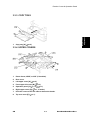
Exterior Covers & Operation Panel
1.
Copy tray [A] (
Replacement
Adjustment
3.3.3 COPY TRAY
x 2).
3.3.4 UPPER COVERS
1.
Platen Cover, ARDF, or ADF (if installed).
2.
Rear cover.
3.
Left upper cover [A] (
4.
Front upper left cover [B] (
5.
Operation panel [C] (
6.
Right upper cover [D] (
7.
Push the cover to the rear side to release the hooks.
8.
Top rear cover [E] (
SM
x 2).
x 4,
x 3).
x 1).
x 1, 3 hooks).
x 1).
3-5
B245/B268/B269/B276/B277
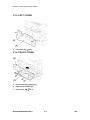
Exterior Covers & Operation Panel
3.3.5 LEFT COVER
1.
Left cover [A] (
x 3).
3.3.6 FRONT COVER
1.
Pull out the (top) paper tray.
2.
Open the front door [A].
3.
Front cover [B] (
x 4).
B245/B268/B269/B276/B277
3-6
SM
Exterior Covers & Operation Panel
Replacement
Adjustment
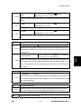
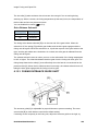
3.3.7 FRONT RIGHT COVER
1.
Open the front door [A].
2.
Front right cover [B] (
x 1).
3.3.8 RIGHT REAR COVER
p.3-5).
1.
Right upper cover (
2.
Open the duplex unit (B269/B277 only).
3.
Right rear cover [A] (
SM
x 1).
3-7
B245/B268/B269/B276/B277
Exterior Covers & Operation Panel
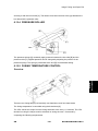
3.3.9 RIGHT DOOR (DUPLEX UNIT (B269/B277))
1.
Right rear cover (see above).
2.
Open the right door [A].
3.
Open the clamps [B] and disconnect the two connectors [C] or three connectors
(B269/B277).
4.
Right door
3.3.10 BY-PASS TRAY
1.
Right rear cover (above).
2.
Open the right door.
B245/B268/B269/B276/B277
3-8
SM
Exterior Covers & Operation Panel
3.
Release the by-pass tray cable from the clamps (see [B] on the preceding
procedure) and disconnect the connector (5-pin connector with colored wires).
4.
Cable holder [A] (B269/B277 only).
5.
Front-side clip ring [B].
6.
Front-side pin [C] (You can push the pin from behind the right door.).
7.
Front-side tray holder arm [D].
8.
Remove the rear-side clip ring, pin, and tray holder arm in the same manner.
9.
By-pass tray [E].
Replacement
Adjustment
3.3.11 LEFT LOWER COVER (TWO-TRAY MODELS ONLY)
1.
Left lower cover [A] (
x 2).
3.3.12 RIGHT LOWER COVER (TWO-TRAY MODELS ONLY)
1.
SM
Right lower cover [A] (1 pin).
3-9
B245/B268/B269/B276/B277
Exterior Covers & Operation Panel
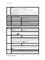
3.3.13 PLATEN COVER SENSOR
1.
Top rear cover.
2.
Platen cover sensor [A] (
B245/B268/B269/B276/B277
x 1).
3-10
SM
Scanner Unit
3.4 SCANNER UNIT
Replacement
Adjustment
3.4.1 EXPOSURE GLASS/DF EXPOSURE GLASS
- Exposure Glass 1.
Front upper left cover (
2.
Left scale [A] (
x 2).
3.
Rear scale [B] (
x 3.
4.
Exposure glass [C]
-6850556.
Upper Covers).
Make sure that the mark is at the rear left corner, and that the left edge is
aligned to the support on the frame when you reinstall the exposure glass.
- DF Exposure Glass 1.
Front upper left cover (
2.
Left scale [A].
3.
DF exposure glass [D].
-6850556.
Upper Covers).
Make sure that the mark [E] is on the bottom at the front end when
reinstall the exposure glass.
3.4.2 LENS BLOCK
-21. Do not touch the paint-locked screws on the lens block. The position of the lens
assembly (black part) is adjusted before shipment.
-20. Do not grasp the PCB or the lens assembly when you handle the lens block. The
SM
3-11
B245/B268/B269/B276/B277
Scanner Unit
lens assembly may slide out of position.
1.
Exposure glass (
2.
Lens cover [A] (
3.
Disconnect the flat cable [B].
4.
Lens block [C] (
-6850556.
Scanner Unit).
x 5).
x 4).
Adjust the image quality (
Copy Adjustments Printing/Scanning)
after you install a new lens block.
3.4.3 LAMP STABILIZER BOARD AND EXPOSURE LAMP
1.
Operation panel (
Upper Covers).
2.
Exposure glass (
Exposure Glass/DF Exposure Glass).
3.
Slide the first scanner to a position where the front end of the lamp is visible.
4.
Place one hand under the lamp stabilizer board [A] and release the hook [B].
B245/B268/B269/B276/B277
3-12
SM
Scanner Unit
5.
Lamp stabilizer board (
x 2).
6.
Press the plastic latch [C] and push the front end of the lamp toward the rear.
7.
Lamp [D] (with the cable).
Replacement
Adjustment
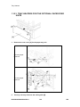
3.4.4 ORIGINAL WIDTH/LENGTH SENSOR
1.
Exposure glass (
2.
Original width sensor [A] (
3.
Lens block (
4.
Original length sensor [B] (
SM
Scanner Unit).
x 1,
x 1).
Scanner Unit).
x 1,
x 1).
3-13
B245/B268/B269/B276/B277
Scanner Unit
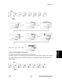
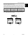
- Sensor Positions Sensor positions vary according to regions as shown below.
Asia (including Taiwan; excluding China),
Europe
America
China (Sensor positions for China model (8K/16K)
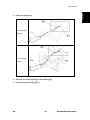
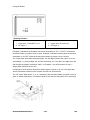
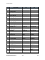
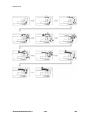
- Sensor Positions for China Model (8K/16K) This procedure is for China models only. You must rearrange the positions of the original
width and length sensors for the copier to detect the following original sizes:
1. 8K SEF (270 x 390 mm)
2. 16K SEF (195 x 270 mm)
3. 16K LEF (270 x 195 mm)
After you have rearranged the positions, the sensors work as listed in the table. Rearrange
the sensor positions as follows:
Original Size
1.
Length Sensors
Width Sensors
8K-SEF
L1
L2
W1
W2
16K-SEF
X
X
X
O
16K-LEF
X
O
O
O
16K-SEF
O
O
X
O
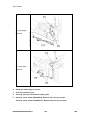
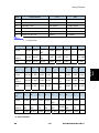
Specify SP mode settings:
Select SP 4305 1, and specify 2 (=Yes). The machine will detect 8K/16K rather than
B245/B268/B269/B276/B277
3-14
SM
Scanner Unit
A3/A4/B4/B5 (A3-SEF/B4-SEF
B5-LEF/A4-LEF
8K-SEF; B5-SEF/A4-SEF
16K-SEF;
16K-LEF).
2.
Turn off the main switch.
3.
Exposure glass (
4.
Original width/length sensors [A] [B]
5.
Rearrange the sensor positions [C] [D].
6.
Turn on the main switch and check the operations.
Scanner Unit).
Replacement
Adjustment
3.4.5 SCANNER MOTOR
1.
Left upper cover, front upper left cover, operation panel, top rear cover
(
Exposure Glass/DF Exposure Glass).
Exposure Glass/DF Exposure Glass).
2.
Exposure glass (
3.
Rear exhaust fan [A] (B269/B277 only).
4.
Scanner motor [B] ( x 3,
x 1, 1 spring, 1 belt).
-21. Install the belt first, and then set the spring when you reassemble. Fasten the
leftmost screw (viewed from the rear), and fasten the other two screws.
-20. Adjust the image quality after you install the motor.
SM
3-15
B245/B268/B269/B276/B277
Scanner Unit
3.4.6 SCANNER HOME POSITION SENSOR
1.
Left upper cover, top rear cover (
Original Width/Length Sensor).
2.
Exposure glass, DF exposure glass (if installed) (
Exposure Glass/DF
Exposure Glass).
3.
Disconnect the connector [A].
4.
Scanner left lid [B] (
5.
Sensor tape [C].
6.
Scanner home position sensor [D].
B245/B268/B269/B276/B277
x 7).
3-16
SM
Scanner Unit
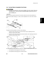
3.4.7 ADJUSTING SCANNER POSITIONS
-21. Grasp the front and rear ends (not the middle) of the first scanner when you
manually move it. The first scanner may be damaged if you press, push, or
pull its middle part.
- Overview Adjust the scanner positions when the first scanner [C] and second scanner [B] are not
parallel with the side frames [A], or, when you have replaced one or more of the scanner
Replacement
Adjustment
belts.
To adjust the scanner positions, do either of the following:
1. Adjust the belt contact points on the first scanner. (See " Adjusting the First
Scanner Contact Points" below.).
2. Adjust the belt contact points on the scanner bracket. (See ”Adjusting the Second
Scanner Contact Points" below.).
The two actions above have the same objectives--to align the following holes and marks:
1. The adjustment holes [H] [J] in the first scanner
2. The adjustment holes [H] [J] in the second scanner
SM
3-17
B245/B268/B269/B276/B277
Scanner Unit
3. The alignment marks [G] [I] on the frames
The scanner positions are correct when these holes and marks are aligned.
- Adjusting the First Scanner Contact Points -
1.
A(R)DF or platen cover.
2.
Operation panel, top rear cover (
3.
Exposure glass (
4.
Loosen the 2 screws [A] [F].
5.
Slide the 1st and 2nd scanners, or one of them, to align the following holes and
Upper Covers).
Exposure Glass/DF Exposure Glass).
marks.
6.
The adjustment holes in the first scanner.
7.
The adjustment holes in the second scanner.
8.
The alignment marks on the frames.
9.
Insert the positioning tools [D] [E] through the holes and marks.
10. Check that the scanner belts [B] [C] [G] [H] are properly set between the bracket
and the 1st scanner.
11. Tighten the screws [A] [F].
12. Remove the positioning tools.
13. Reassemble the machine and check the operation.
B245/B268/B269/B276/B277
3-18
SM
Scanner Unit
1.
A(R)DF or platen cover.
2.
Operation panel, top rear cover (
3.
Exposure glass (
4.
Rear exhaust fan [A] (
5.
Controller bracket [B] (
6.
Disconnect the platen-cover-sensor connector [C].
7.
Rear frame [D] (
8.
Scale bracket [E] (
9.
Loosen the 2 screws [F].
Replacement
Adjustment
- Adjusting the Second Scanner Contact Points -
Upper Cover).
Exposure Glass/DF Exposure Glass).
x 2).
x 3).
x 7).
x 2).
10. Slide the 2nd scanner to align the following holes and marks.
SM
3-19
B245/B268/B269/B276/B277
Scanner Unit
11. The adjustment holes in the first scanner.
12. The adjustment holes in the second scanner.
13. The alignment marks on the frames.
14. Insert the positioning tools [G] [H] through the holes and marks.
15. Check that the scanner belts are properly set in the brackets.
16. Remove the positioning tools.
17. Reassemble the machine and check the operation.
B245/B268/B269/B276/B277
3-20
SM
Laser Unit
3.5 LASER UNIT
-21. The laser beam can seriously damage your eyes. Be absolutely sure that the
main power switch is off and that the machine is unplugged before you
access the laser unit.
Replacement
Adjustment
3.5.1 LOCATION OF CAUTION DECAL
3.5.2 TONER SHIELD GLASS
1.
Open the front door.
2.
Lift the toner cartridge latch [A].
3.
Press the toner shield glass cover [B] to the left and pull it out.
SM
3-21
B245/B268/B269/B276/B277
Laser Unit
4.
Pull out the toner shield glass [C].
3.5.3 LASER UNIT
1.
Toner shield glass.
2.
Copy tray.
3.
Pull out the (upper) paper tray.
4.
Front cover .
5.
Laser unit [A] (
x 2,
x 4).
-21. The screw at the left front position [B] is longer than the other three.
B245/B268/B269/B276/B277
3-22
SM
Laser Unit
3.5.4 LD UNIT
-21. Do not touch the paint-locked screw [A]. The LD position is adjusted before
Replacement
Adjustment
shipment.
1.
Laser unit.
2.
LD unit [B] (
x 1).
-21. Do not screw the LD unit in too tightly when you install it.
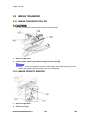
3.5.5 POLYGONAL MIRROR MOTOR
SM
3-23
B245/B268/B269/B276/B277
Laser Unit
1.
Laser unit.
2.
Two rubber bushings [A].
3.
Laser unit cover [B] (
4.
Polygonal mirror motor [C] (
5.
After reassembling, adjust the image quality. (
x 1).
x 4).
Copy Adjustments
Printing/Scanning).
6.
Laser Unit Alignment Adjustment.
-21. Reinstall the copy exit tray before you turn the main switch on. The laser
beam may go out of the copier when the copy exit tray is not installed. The
laser beam can seriously damage your eyes.
1.
Start the SP mode.
2.
Select SP 5902-1 and output the ‘Trimming Area’ pattern (pattern 10).
3.
Make sure that the four corners of the pattern make right angles:
-21. If they make right angles, you do not need to adjust the laser unit alignment.
-20. If they do not make right angles, go on to the next step.
4.
Check the screw position on the lever [B].
-21. If the screw is in the hole [C], go on to the next step.
-20. If the screw is in the slot [D], loosen the screw on the lever, loosen the four screws
on the laser unit, and go on to step 9.
-6850556.
5.
The initial position of the screw is in hole [C].
Four screws in the laser unit (
B245/B268/B269/B276/B277
Laser Unit).
3-24
SM
Laser Unit
6.
Remove the lever (
x 1), confirm the position of the hole beneath the slot [D],
and reinstall the lever.
7.
Install the screw (through the slot [D]) loosely into the hole beneath the slot (do
not tighten the screw).
8.
Install the four screws for the laser unit loosely (do not tighten the screws).
9.
When you rotate the lever clockwise or counterclockwise by one notch of the
lever, the corners of the pattern shift by 0.4 mm (from the leading and trailing
edges). See the trim pattern made in step 2, and find how much the corners
Replacement
Adjustment
should be shifted.
10. Tighten the screw [A].
11. Tighten the screws on the laser unit.
12. Reinstall the copy tray.
13. Print the trim pattern and check the result. Do the procedure again if further
adjustment is required.
SM
3-25
B245/B268/B269/B276/B277
PCU Section
3.6 PCU SECTION
3.6.1 PCU
1.
Toner bottle with the holder [A].
2.
Open the right door.
3.
Press the latch [B] and pull out the PCU [C].
-6850556.
Do not touch the OPC drum surface with bare hands.
p.3-30).
4.
Load new developer (
5.
Do SP 2214 to reinitialize the TD sensor when you reassemble.
B245/B268/B269/B276/B277
3-26
SM
PCU Section
3.6.2 PICK-OFF PAWLS AND TONER DENSITY SENSOR
Replacement
Adjustment
-21. Do not turn the PCU upside down. This causes toner and developer to spill out.
1.
PCU (
2.
Pawl [A].
-6850556.
3.
Previous procedure).
Pull down the pawl and release the bottom end.
Toner density sensor [B] (
-6850556.
x 1).
The toner density sensor is taped to the bottom of the PCU. Pry it off with
a regular screwdriver
4.
After reinstalling the pick-off pawls or toner density sensor, adjust the image
quality (
SM
After Replacement and Adjustment).
3-27
B245/B268/B269/B276/B277
PCU Section
3.6.3 OPC DRUM
PCU).
1.
PCU (
2.
Front side piece [A] (
3.
Rear side piece [B] (
4.
Separate the drum section [C] from the developer section [D].
-6850556.
x 1).
x 2, 1 coupling).
To ensure that the left-side gears line up, keep the drum cover [E] closed
when reinserting the front side piece.
5.
Pry out the drum retaining clip [F].
-6850556.
Install the clip in the same orientation (with the lip facing away from the
drum shaft) when you reassemble.
6.
OPC drum [G]
7.
When reassembling, adjust the image quality (
After Replacement and
Adjustment).
B245/B268/B269/B276/B277
3-28
SM
PCU Section
Replacement
Adjustment
3.6.4 CHARGE ROLLER AND CLEANING BRUSH
Previous procedure).
1.
OPC Drum (
2.
Holding pin [A].
3.
Stepped screw [B].
4.
Charge roller [C] and cleaning brush [D] (with the holders and springs).
-6850556.
5.
Turn the gear [E] (as necessary) so that the rear holder [F] comes out.
When reassembling, adjust the image quality (
After Replacement and
Adjustment).
3.6.5 CLEANING BLADE
1.
Drum charge roller (
2.
Cleaning blade [B] (
3.
When reassembling, adjust the image quality (
Previous procedure).
x 2).
After Replacement and
Adjustment).
SM
3-29
B245/B268/B269/B276/B277
PCU Section
Reassembling
Apply toner to the edge of the new cleaning blade when you replace the cleaning blade.
This prevents possible damage to the OPC drum and blade.
1. After installing the cleaning blade, remove some of the toner from the old
blade with your finger.
2. Apply the toner to the edge [A] of the new cleaning blade. Make sure to
apply the toner evenly along full length of the new cleaning blade.
3.6.6 DEVELOPER
1.
PCU (
2.
To let the toner fall to the development section, gently tap about eight different
PCU).
spots on the top of the PCU with a screwdriver. Each spot must be
approximately at an equal distance from the next spot.
3.
Reinstall the PCU in the copier.
4.
Turn the main switch on.
5.
Open and close the front door and wait for the machine to rotate the
development roller for about 10 seconds.
6.
Repeat the previous step two more times.
7.
PCU (
8.
Separate the developer section from the OPC drum section (
9.
Top part [A] of the development unit (
PCU).
B245/B268/B269/B276/B277
OPC Drum).
x 5).
3-30
SM
PCU Section
•
Release the hook [B].
10. Set the coupling [C] back to the shaft.
11. Turn the coupling in the direction of the arrow [D] to remove developer from the
roller.
12. Turn the bottom part [E] over and rotate the gears to remove the developer.
13. Load new developer (
p.1-5).
•
Make sure no toner or developer stays on the gear. Clean the gears as
necessary with a blower brush, etc.
•
Be sure to replace the Mylar at the rear side in the correct position. (The
Mylar protects the gears at the rear side from falling toner).
3.6.7 AFTER REPLACEMENT OR ADJUSTMENT
•
Do the following procedure after replace or adjust any of the PCU
components. This procedure is not necessary when you replaced the whole
PCU with a new one.
1.
Take 5 sample copies.
2.
If black dots (dropped toner) show on any of the copies, continue as follows. (If
all copies are clean, you don't need to do the following steps.)
3.
Remove the PCU from the mainframe.
4.
Tap the top of the PCU with a screwdriver at eight evenly spaced locations (two
or three taps at each spot), to knock the recycled toner down into the
development section.
5.
Put the PCU back into the mainframe.
6.
Turn the main power on. Then open and close the door and wait for the machine
to rotate the development roller for 10 seconds. Then open and close the door
two more times, so that total rotation time is 30 seconds.
7.
Make some sky-shot copies (or solid black prints).
•
If using A4 or 81/2" x 11" paper, make 4 copies/prints.
•
If using A3 or 11" x 17" paper, make 2 copies/prints.
•
To make solid black prints, use SP 5902 pattern 8.
•
Step 7 is required only after parts replacement or adjustment. You do not need to
make sky-shot (or solid black) copies after you replace the developer.
SM
3-31
B245/B268/B269/B276/B277
Replacement
Adjustment
14. When reassembling, execute SP 2214 to reinitialize the TD sensor.
Toner Supply Motor
3.7 TONER SUPPLY MOTOR
Upper Covers).
1.
Copy tray (
2.
Open the front door.
3.
Toner bottle holder (
4.
Toner supply motor [A] (
B245/B268/B269/B276/B277
PCU).
x 1).
3-32
SM
Paper Feed Section
3.8 PAPER FEED SECTION
Replacement
Adjustment
3.8.1 PAPER FEED ROLLER
1.
Paper cassette.
2.
Clip [A].
3.
Push the shaft back through the opening, and tilt it up.
-6850556.
If the black plastic bushing [B] comes off, make sure you remount it when
reinstall the shaft.
4.
Paper feed roller [C]
3.8.2 FRICTION PAD
1.
Paper cassette.
2.
Clip [A].
SM
3-33
B245/B268/B269/B276/B277
Paper Feed Section
3.
Push the shaft back through the opening, so that the roller moves clear of the
friction pad.
4.
Friction pad [B]
3.8.3 PAPER END SENSOR
1.
Paper cassette.
2.
Paper end sensor [A] (
x 1).
3.8.4 EXIT SENSOR
- Non-Duplex Models -
1.
Open the right door.
2.
Front right cover).
3.
Guide [A] (
x 2).
B245/B268/B269/B276/B277
3-34
SM
Paper Feed Section
4.
Exit sensor bracket [B] (
5.
Exit sensor [C] (
x 1).
x 1).
Replacement
Adjustment
- Duplex Models -
1.
Open the right door.
2.
Front right cover.
3.
Upper guide [D] (
4.
Exit sensor bracket [E] (
5.
Exit sensor [F] (
x 2).
x 1).
x 1).
3.8.5 BY-PASS FEED ROLLER AND PAPER END SENSOR
SM
3-35
B245/B268/B269/B276/B277
Paper Feed Section
1.
By-pass tray.
-6850556.
If you have a support to keep the by-pass tray within the reach of the
connector cable, you do not need to disconnect the connector. When you do so,
use caution not to place too much load on the cable.
2.
Sensor holder [A].
3.
By-pass paper end sensor [B] (
4.
By-pass feed roller [C].
x 1).
3.8.6 REGISTRATION ROLLER
1.
PCU.
2.
Front cover.
3.
Right door .)
4.
Rear cover.
5.
High-voltage power supply .
B245/B268/B269/B276/B277
3-36
SM
Paper Feed Section
6.
Registration clutch.
7.
Unhook the springs [A] and [B] at the rear and front sides.
8.
Guide support [C] and guide [D] (
9.
Bushing [E] (
x 1,
x 1).
x 1).
10. Gear [F] and bushing [G] (
x 1).
11. Registration roller [H] with the image transfer unit [I].
Replacement
Adjustment
3.8.7 BY-PASS PAPER SIZE SWITCH
1.
By-pass tray.
2.
Tray lever [A] (
3.
Lift the upper tray [B].
4.
By-pass paper size switch [C] ( x 1).
-6850556.
x 1, 1 pin).
When reinstalling the switch: Move the paper guides to their middle
position (about halfway between fully open and fully closed), and install the round
gear so that the hole in the gear [D] aligns with the peg [E] on the sliding gear.
SM
3-37
B245/B268/B269/B276/B277
Paper Feed Section
3.8.8 REGISTRATION CLUTCH
1.
Rear cover.
2.
High-voltage power supply board (with the bracket) [A] (
3.
Registration clutch [B] (
x 1,
x 4, all connectors).
x 1).
3.8.9 REGISTRATION SENSOR
1.
Open the right door.
2.
Registration sensor [A] (
B245/B268/B269/B276/B277
x 1).
3-38
SM
Paper Feed Section
Replacement
Adjustment
3.8.10 UPPER PAPER FEED CLUTCH AND BY-PASS FEED
CLUTCH
1.
Rear cover.
2.
High-voltage power supply board.
3.
Clutch cover [A] (
4.
Paper feed clutch [B] (
5.
By-pass feed clutch [C] (
-6850556.
x 2, 2 bushings,
x 2 ).
x 1).
x 1).
Make sure that the rotation-prevention tabs [D] on the clutches fit
correctly into the corresponding openings on the clutch cover when you reinstall.
3.8.11 RELAY CLUTCH
1.
SM
Rear cover.
3-39
B245/B268/B269/B276/B277
Paper Feed Section
2.
Relay clutch [A] (
x 1).
3.8.12 RELAY SENSOR
1.
Relay clutch (Previous procedure).
2.
Sensor bracket [A] (
3.
Relay sensor [B] (
x 1).
x 1).
3.8.13 LOWER PAPER FEED CLUTCH (TWO-TRAY MODELS
ONLY)
1.
Rear lower cover (
2.
Clutch bracket [A] (
3.
Lower paper feed clutch [B] (
Rear Lower Cover (Two-tray Models Only).
x 2).
B245/B268/B269/B276/B277
x 2, 1 bushing,
3-40
x 1).
SM
Paper Feed Section
Rear Lower Cover (Two –tray Models Only).
1.
Right lower cover (
2.
Metal plate [A] (
3.
Vertical transport sensor [B] (
x 3).
x 1).
3.8.15 PAPER SIZE SWITCH
1.
Paper cassette.
2.
Switch cover [A] (
3.
Paper size switch [B] (
SM
x 1).
x 1).
3-41
B245/B268/B269/B276/B277
Replacement
Adjustment
3.8.14 VERTICAL TRANSPORT SENSOR (TWO-TRAY MODELS
ONLY)
Image Transfer
3.9 IMAGE TRANSFER
3.9.1 IMAGE TRANSFER ROLLER
-21. Do not touch the transfer roller surface with bare hands.
1.
Open the right door.
2.
Lift the plastic holders [A] with the image transfer roller [B].
-6850556.
Leave the springs under the holders. Make sure that the pegs [C] on the
holders [D] engage with the springs when you reassemble.
3.9.2 IMAGE DENSITY SENSOR
1.
Open the right door.
2.
Plastic cover [A].
B245/B268/B269/B276/B277
3-42
SM
Image Transfer
3.
Image transfer roller (Previous procedure).
4.
Push down on the notch [B] to free the sensor.
5.
Image density sensor [C] (
Replacement
Adjustment
x 1).
SM
3-43
B245/B268/B269/B276/B277
Fusing
3.10 FUSING
3.10.1 FUSING UNIT
-21. The fusing unit can become very hot. Make sure that it has cooled down
sufficiently before you handle it.
1.
Turn off the main switch, and unplug the machine.
2.
Front right cover.
3.
Open the right door.
4.
Fusing unit [A] (
x 2,
x 4).
3.10.2 THERMISTOR
1.
Fusing unit (see above).
2.
Thermistors [A] (
x 1,
B245/B268/B269/B276/B277
x 1).
3-44
SM
Fusing
Replacement
Adjustment
3.10.3 FUSING LAMPS
1.
Fusing unit.
2.
Separate the hot roller section [A] from the pressure roller section [B] (
3.
Front holding plate [C] (
4.
Rear holding plate [D] (
5.
Fusing lamp with the connector (600W) [E] (
x 2).
6.
Fusing lamp with the connector (550W) [F] (
x 2).
-6850556.
x 4).
x 1).
x 1).
Check that the front ends of the two lamps fit in the front holding plate
when you reassemble. If the lamps are seated incorrectly, they do not fit in the
holding plate.
SM
3-45
B245/B268/B269/B276/B277
Fusing
3.10.4 HOT ROLLER STRIPPER PAWLS
1.
Hot roller section (See above).
2.
Roller guard [A] (
3.
Metal holders [B] (1 holder for each).
4.
Hot roller stripper pawls [C] (1 spring for each).
x 3).
3.10.5 HOT ROLLER
1.
Hot roller stripper pawls (See above).
2.
Hot roller [A] (2 C-rings, 1 gear, 2 bearings).
B245/B268/B269/B276/B277
3-46
SM
Fusing
1.
Hot roller (See above).
2.
Thermostat [A] (
Replacement
Adjustment
3.10.6 THERMOSTAT
x 2 for each).
3.10.7 PRESSURE ROLLER AND BUSHINGS
1.
Separate the hot roller section from the pressure roller section (
Fusing
Lamps).
2.
Fusing entrance guide [A] (
3.
2 springs [B].
4.
2 pressure arms [C].
5.
2 Bushings [D].
SM
x 2).
3-47
B245/B268/B269/B276/B277
Fusing
6.
Pressure roller [E]
3.10.8 NIP BAND WIDTH ADJUSTMENT
Do this adjustment when the fusing unit is at its operating temperature. The size of the
OHP sheet must be A4/LT LEF. Any other sizes may cause a paper jam.
A. Pressure roller
B. Hot roller
1.
Place an OHP sheet on the by-pass feed table.
2.
Enter SP mode, and run SP 1109.
3.
Press ‘1’ (Yes).
4.
Press
twice. The machine feeds the OHP sheet into the fusing section, stops
it there for 20 seconds, then ejects it to the copy tray.
5.
Press the
6.
Quit the SP mode.
7.
Check that the nip band (the opaque stripe) across the ejected OHP sheet is
key.
symmetrical, with both ends slightly thicker than the center.
-6850556.
There is no standard value for the nip band on this machine. Make the
adjustment based on the band's appearance.
8.
If the band is not as described above, change the position of the spring hooks
[C] (one on each side), and then check the band again.
-6850556.
The higher hook position produces greater tension.
B245/B268/B269/B276/B277
3-48
SM
Fusing
1.
Pressure roller and bushings (
2.
Cleaning roller [A]
SM
Replacement
Adjustment
3.10.9 CLEANING ROLLER
p.3-47)
3-49
B245/B268/B269/B276/B277
Duplex Unit (Duplex Models B269/B277 Only)
3.11 DUPLEX UNIT (DUPLEX MODELS B269/B277
ONLY)
3.11.1 DUPLEX EXIT SENSOR
1.
Open the right door.
2.
Sensor bracket [A] (
-6850556.
3.
x 1).
Another bracket [B] comes off with the sensor bracket.
Duplex exit sensor [C] (
x 1).
3.11.2 DUPLEX ENTRANCE SENSOR
1.
Open the right door.
2.
Lift the duplex guide [A].
3.
Entrance sensor bracket [B] and bracket cover [C] (
4.
Duplex entrance sensor [D].
B245/B268/B269/B276/B277
3-50
x 2).
SM
Duplex Unit (Duplex Models B269/B277 Only)
Replacement
Adjustment
3.11.3 DUPLEX INVERTER SENSOR
1.
Copy tray [A] (
x 2).
2.
Exit cover [B] (
x 1).
3.
Sensor bracket [C] (
4.
Duplex inverter sensor [D] (
x 1,
x 1).
x 1).
3.11.4 DUPLEX TRANSPORT MOTOR
1.
SM
Open the right door.
3-51
B245/B268/B269/B276/B277
Duplex Unit (Duplex Models B269/B277 Only)
2.
Detach the chain and spring from the frame, and lower the right door.
3.
Cover [A] (
4.
Motor bracket [B] (
5.
Duplex transport motor [C] (
x 1).
x 4,
x 1).
x 2).
3.11.5 DUPLEX INVERTER MOTOR
1.
Rear cover
2.
Exhaust fan (
3.
Duplex inverter motor [A] (
Rear Exhaust Fan {B269/B277 Only}).
x 2,
x 1).
3.11.6 DUPLEX CONTROL BOARD
1.
Rear lower cover (
2.
Duplex control board [A] (
B245/B268/B269/B276/B277
Rear Lower Cover Two-tray Models Only).
x 4 , all connectors).
3-52
SM
Other Replacements
3.12 OTHER REPLACEMENTS
Replacement
Adjustment
3.12.1 QUENCHING LAMP
1.
PCU (
2.
Quenching lamp [A] (
p.3-26 ).
x 1).
3.12.2 HIGH-VOLTAGE POWER SUPPLY BOARD
1.
Rear cover .
2.
High-voltage power supply board [A] (
SM
x 2, 3 standoffs, all connectors).
3-53
B245/B268/B269/B276/B277
Other Replacements
3.12.3 BICU (BASE-ENGINE IMAGE CONTROL UNIT)
1.
Rear cover.
2.
BICU [A] (
x 7, all connectors, 2 flat cables).
-6850556.
Remove the NVRAM [B] from the old BICU and install it on the new BICU
when you replace the BICU. The NVRAM keeps machine-specific data.
3.12.4 MAIN MOTOR
1.
Rear cover.
2.
Main motor [A] (
x 4,
B245/B268/B269/B276/B277
x 1).
3-54
SM
Other Replacements
1.
Rear cover.
2.
Rear exhaust fan [A] (
x 2,
Replacement
Adjustment
3.12.5 REAR EXHAUST FAN (B269/B277 ONLY)
x 1).
-21. Reassembling -20. Make sure that the arrow on the fan [B] points the outside of the copier when you
reassemble The arrow indicates the direction of the air current.
3.12.6 LEFT EXHAUST FAN
1.
Rear cover.
2.
Left cover.
3.
Fan cover [A] (
4.
Fan [B] (
SM
x 3,
x 3).
x 1).
3-55
B245/B268/B269/B276/B277
Other Replacements
-21. Reassembling -20. Make sure that the arrow on the fan [C] points the outside of the copier when you
reassemble. (The arrow indicates the direction of the air current).
3.12.7 PSU (POWER SUPPLY UNIT)
1.
Left cover.
2.
PSU [A] (All connectors,
B245/B268/B269/B276/B277
x 6).
3-56
SM
Other Replacements
Replacement
Adjustment
3.12.8 GEARBOX
- Replacement Procedure 1.
Inverter tray [A].
2. Two screws [B] from the middle rear cover.
•
This step releases the topmost part of the BICU bracket.
3. High-voltage power supply board (with the bracket) (
Registration
Clutch).
4. BICU (with the bracket) [C] (
•
x 6).
If you have difficulty to remove the bracket, remove the screw at the middle of
the crosspiece (see step 6).
5. Main motor (
6. Crosspiece [D] (
p.3-54).
x 3).
7. Registration clutch.
SM
3-57
B245/B268/B269/B276/B277
Other Replacements
8. PCU.
•
This step releases the gear (on the gearbox) that drives the PCU.
9. Ground plate [E] (
10. Gearbox [F] (
x 2).
x 5, 1 belt).
Do not change the position of the spring [G] and make sure that the bushing [H] on
the PCU drive shaft is in the correct position you when you reassemble. You can
adjust its position by rotating the gear [I] seen from the opening of the gearbox.
B245/B268/B269/B276/B277
3-58
SM
Other Replacements
Replacement
Adjustment
- Gear Arrangement in the Gearbox -
The gears are numbered 1 to 12, in the order in which they are to be installed in the
gearbox. These numbers show both on the gearbox and on the front (exposed) surface of
each gear. If the gears fall out, start by finding gear number 1 and installing it onto location
number 1 (setting it into place so that the side with the printed number stays visible). Then
install the remaining gears (2 to 12) in the same way.
SM
3-59
B245/B268/B269/B276/B277
Copy Adjustments Printing/Scanning
3.13 COPY ADJUSTMENTS PRINTING/SCANNING
You need to perform the adjustment after you do a Memory All Clear, and after you
replace or adjust any of the following parts.
•
First or second scanner
Lens Block
Scanner Motor
Polygonal Mirror Motor
Paper Tray
Paper Side Fence
For detailed explanations about how to access and use the SP modes, see
Section 5.
3.13.1 PRINTING
•
Make sure the paper is installed correctly in each paper tray before you start
these adjustments.
•
Use the Trimming Area Pattern (SP 5902, No.10) to print the test pattern for
the printing adjustments below.
•
Set SP 5902 to 0 again after you complete these printing adjustments.
- Registration - Leading Edge/Side-to-Side 1. Check the leading edge registration for each paper feed
station, and adjust each of these registrations using SP 1001.
2. Check the side-to-side registration for each paper feed station,
and adjust these registrations using SP 1002. (Adjust the trays
in order: the 1st tray first, then the 2nd tray, etc.)
Tray
SP mode
Any paper tray
SP 1001 1
By-pass feed
SP 1001 2
Duplex
SP 1001 3
1st tray
SP 1002 1
2nd tray
SP 1002 2
3rd tray
(Optional PFU tray 1)
B245/B268/B269/B276/B277
Specification
2
1.5 mm
SP 1002 3
3-60
SM
Copy Adjustments Printing/Scanning
Tray
SP mode
By-pass feed
SP 1002 4
Duplex
SP 1002 5
Specification
A: Leading Edge Registration
B: Side-to-side Registration
- Blank Margin If the leading edge or side-to-side registration cannot be adjusted to within the
specification, then adjust the leading-edge blank margin or the left-side blank
margin.
1. Check the trailing edge and right side edge blank margins, and adjust
them using the following SP modes.
SP mode
Trailing edge
SP 2101 2
Right edge
SP 2101 4
Leading edge
SP 2101 1
Left edge
SP 2101 3
Specification
2 +2.5/–1.5 mm
2
1.5 mm
A: Trailing Edge Blank Margin
B: Right Edge Blank Margin
C: Leading Edge Blank Margin
D: Left Edge Blank Margin
- Main Scan Magnification 1. Print the single-dot grid pattern (SP 5902 1).
2. Check the magnification (the grid size should be 2.7 x 2.7 mm), and if
necessary use SP 2998 to adjust it. The specification is 100
SM
3-61
1%.
B245/B268/B269/B276/B277
Replacement
Adjustment
•
Copy Adjustments Printing/Scanning
3.13.2 SCANNING
•
Before doing the following scanner adjustments, check and adjust the printing
leading-edge and side-to-side registrations and the printing blank margins (as
described above).
•
Use an A3 test chart to perform the following adjustments.
- Registration: Platen Mode 1. Place the test chart on the exposure glass and make a copy from one of
the feed stations.
2. Check the leading edge and side-to-side registration, and adjust as
necessary with the following SP modes.
SP mode
Leading edge
SP 4010
Side-to-side
SP 4011
Specification
2
1.5 mm
A: Leading edge registration
B: Side-to-side registration
- Magnification -
A: Main scan magnification
B: Sub-scan magnification
B245/B268/B269/B276/B277
3-62
SM
Copy Adjustments Printing/Scanning
- Main Scan Magnification 1. Place the A3 test chart on the exposure glass and make a copy from one
of the feed stations.
2. Check the magnification ratio. If necessary, adjust the magnification using
the following SP mode.
SP mode
Specification
SP 4009
1.0%
Main Scan Magnification
1. Place the OS-A3 test chart on the exposure glass and make a copy from
one of the feed stations.
2. Check the magnification ratio. If necessary, adjust the magnification with
the following SP mode.
SP mode
Specification
SP 4008
1.0%
Sub-scan magnification
- Standard White Density Adjustment -
This procedure adjusts the standard white density level. Do this adjustment after you do
any of the following:
1. After you replace the standard white plate.
2. After you replace the NVRAM on the BICU. (But note that you do not need to carry
out this adjustment if you have replaced the BICU itself but retained the previous
NVRAM board [by moving it over onto the new BICU]).
3. After you perform a memory all clear (SP 5801 2).
Procedure:
1.
Place 10 sheets of new A4/LTR paper (sideways, LEF) or new A3/DLT paper on
the exposure glass, and close the platen cover or the ADF.
2.
Enter SP 4428 1 and select “1: YES”. The machine automatically adjusts the
standard white density.
SM
3-63
B245/B268/B269/B276/B277
Replacement
Adjustment
- Sub-Scan Magnification -
Copy Adjustments Printing/Scanning
3.13.3 ADF IMAGE ADJUSTMENT
A: Leading edge registration
B: Side-to-side registration
-21. Make a temporary test chart as shown above, using A3/11" x 17" paper.
1.
Place the temporary test chart on the ADF and make a copy from one of the feed
stations.
2.
Check the registrations, and adjust as necessary with the appropriate SP modes,
as follows.
SP mode
Side-to-side registration
SP 6006 1
Leading edge registration
SP 6006 2
Blank margin for the trailing edge
SP 6006 3
Side-to-side registration (Duplex: back side)
SP 6006 4
- Sub-scan Magnification -
A: Sub-scan magnification
-21. Make a temporary test chart as shown above, with A3/11" x 17" paper.
B245/B268/B269/B276/B277
3-64
SM
Copy Adjustments Printing/Scanning
1.
Place the temporary test chart on the ADF and make a copy from one of the feed
stations.
2.
Check the registration, and if necessary adjust it with SP 6006 5. The
1.0%.
Replacement
Adjustment
specification is
SM
3-65
B245/B268/B269/B276/B277
TROUBLESHOOTING
Service Call Conditions
4. TROUBLESHOOTING
4.1 SERVICE CALL CONDITIONS
4.1.1 SUMMARY
There are four levels of service call conditions.
Definition
Reset Procedure
To prevent damage to the machine, the main
A
machine cannot be operated until the SC has
been reset by a service representative (see the
note below).
If the SC was caused by incorrect sensor
B
detection, the SC can be reset by turning the
main power switch off and on.
C
D
Enter SP mode, and then turn
the main power switch off and
on.
Turn the main power switch off
and on.
The main machine can be operated as usual,
Turn the main power switch off
excluding the unit related to the service call.
and on.
The SC history is updated. The machine can be The SC will not be displayed.
operated as usual.
•
Only the SC history is updated.
If the malfunction is potentially related to electrical circuit boards, first
disconnect then reconnect the connectors before replacing the PCBs.
•
If the problem concerns a motor lock, first check the mechanical load
before replacing motors or sensors.
SM
4-1
B245/B268/B269/B276/B277
Troubleshooting
Level
Service Call Conditions
4.1.2 SC CODE DESCRIPTIONS
No.
Symptom
Definition
Possible Cause
Exposure Lamp Error
1. Exposure lamp defective
2. Exposure lamp stabilizer
defective
3. Exposure lamp connector
The standard white level
101
B
was not detected properly
when scanning the white
plate.
defective
4. Dirty scanner mirror or scanner
mirror out of position
5. SBU board defective
6. SBU connector defective
7. Lens block out of position
8. Incorrect position or width of
white plate scanning (
p.5-12)
Scanner home position error 1
1. Scanner home position sensor
defective
The scanner home
120
B
position sensor does not
detect the off condition
during initialization or
2. Scanner drive motor defective
3. Scanner home position sensor
connector defective
4. Scanner drive motor connector
copying.
defective
5. BICU board defective
Scanner home position error 2
1. Scanner home position sensor
defective
The scanner home
121
B
position sensor does not
detect the on condition
during initialization or
2. Scanner drive motor defective
3. Scanner home position sensor
connector defective
4. Scanner drive motor connector
copying.
defective
5. BICU board defective
B245/B268/B269/B276/B277
4-2
SM
Service Call Conditions
No.
Symptom
Definition
Possible Cause
SBU white/black level correction error
The automatic SBU
adjustment has failed to
correct the black level.
143
D
The automatic SBU
1. Exposure lamp defective
2. Dirty white plate
3. Incorrect position or width of
white plate scanning (
adjustment has failed to
correct the white level
twenty times
p.5-12)
4. BICU board defective
5. SBU board defective
consecutively.
Communication Error between BICU and SBU
1. The flat cable between the BICU
144
B
The BICU board cannot
detect the SBU connect
connection
2. The flat cable between the BICU
signal.
board and the SBU is damaged
3. BICU board defective
4. SBU defective
Automatic SBU adjustment error
During the automatic SBU
adjustment, the machine
145
D
detects that the white
level read from the white
plate or paper is out of
range. (
p.5-12)
1. Exposure lamp defective
2. Dirty white plate
3. Incorrect position or width of
white plate scanning
(
p.5-12)
4. BICU board defective
5. SBU board defective
Image transfer error
Scanned images are not
193
B
transferred to the
1. BICU board defective
controller memory within 1
2. Controller board defective
minute.
Memory address error
198
B
The BICU board does not
receive memory
SM
1. The firmware programs of the
engine and the controller do not
4-3
B245/B268/B269/B276/B277
Troubleshooting
board and the SBU has a poor
Service Call Conditions
No.
Symptom
Definition
Possible Cause
addresses from the
match.
controller board.
2. BICU board defective
3. Controller board defective
Charge roller current leak
302
B
A current leak signal for
the charge roller is
1. Charge roller damaged
2. High voltage supply board
defective
detected.
3. Poor connection of the PCU
Polygonal mirror motor error
The polygon mirror motor
does not reach operating
speed within 10 seconds
320
B
after the motor ON signal
is sent, or does not turn
on within one of the 200
ms check intervals during
operation.
1. Polygon mirror motor defective
2. Poor connection between the
polygonal mirror motor driver and
the BICU board
3. Damaged cable between BICU
and polygonal mirror motor driver
4. BICU board defective
No laser writing signal (F-GATE) error
The laser-writing signal
(F-GATE) fails to turn Low
321
C
after the laser crosses 5
mm on the drum surface
from the laser writing start
position.
1. BICU board defective
2. The fax controller or printer
controller has a poor connection
3. Fax controller or printer controller
defective
Laser synchronization error
The main scan
1. Poor connection between the LD
synchronization detector
322
390
B
B
board cannot detect the
laser synchronization
unit and the BICU board
2. Damaged cable between BICU
and LD unit
signal for more than 5
3. LD unit out of position
consecutive 100 ms
4. LD unit defective
intervals.
5. BICU board defective
TD sensor error
B245/B268/B269/B276/B277
4-4
SM
Service Call Conditions
No.
Definition
Symptom
Possible Cause
The TD sensor outputs
less than 0.2 V or more
than 4.0 V 10 times
1. TD sensor abnormal
2. Poor connection of the PCU
consecutively during
copying.
Development bias leak
391
B
A development bias leak
signal is detected.
1. Poor connection of the PCU
2. High voltage supply board
defective
TD sensor initial setting error
1. ID sensor defective
392
B
TD sensor initial setting is
not performed correctly.
3. Drum does not turn
4. Development roller does not turn
5. Poor connection of the PCU
6. The voltage is not applied to
charge roller
Transfer roller leak error 1
A current leak signal for
the transfer roller is
401
B
1. High voltage supply board
defective
detected.
2. Poor connection of the PCU
A current feedback signal
3. Transfer/separation unit set
for the transfer roller is not
detected.
incorrectly
4. Transfer roller damaged
Transfer roller leak error 2
A current leak signal for
the transfer roller is
402
B
defective
detected.
2. Poor connection of the PCU
A current feedback signal
3. Transfer/separation unit set
for the transfer roller is not
detected.
500
SM
B
1. High voltage supply board
incorrectly
4. Transfer roller damaged
Main motor lock
A main motor lock signal
4-5
1. Too much load on the drive
B245/B268/B269/B276/B277
Troubleshooting
2. No developer
Service Call Conditions
No.
Symptom
Definition
Possible Cause
is not detected for more
than 7 consecutive
mechanism
2. Main motor defective
checks (700 ms) after the
main motor starts to
rotate, or the lock signal is
not detected for more
than 7 consecutive
checks during rotation
after the last signal.
Tray 2 lift motor malfunction (Optional paper tray units)
502
C
The paper lift sensor fails
1. Paper lift sensor defective
to activate twice
2. Tray lift motor defective
continuously after the tray
3. Too much load on the drive
lift motor has been on for
18 seconds.
mechanism
4. Poor tray lift motor connection
Tray 3 lift motor malfunction (optional paper tray units)
503
C
The paper lift sensor fails
1. Paper lift sensor defective
to activate twice
2. Tray lift motor defective
continuously after the tray
3. Too much load on the drive
lift motor has been on for
18 seconds.
mechanism
4. Poor tray lift motor connection
Tray 4 lift motor malfunction (optional two-tray paper tray unit)
504
C
The paper lift sensor fails
1. Paper lift sensor defective
to activate twice
2. Tray lift motor defective
continuously after the tray
3. Too much load on the drive
lift motor has been on for
18 seconds.
mechanism
4. Poor tray lift motor connection
Paper feed motor lock (optional paper tray units)
A motor lock signal is not
506
C
detected for more than
1. Paper feed motor defective
1.5 s or the lock signal is
2. Too much load on the drive
not detected for more
mechanism
than 1.0 s during rotation.
B245/B268/B269/B276/B277
4-6
SM
Service Call Conditions
No.
Symptom
Definition
Possible Cause
Fusing thermistor open (center)
The fusing temperature
541
A
detected by the thermistor
is below 71C and is not
corrected after the main
power switch is turned on.
1. Fusing thermistor defective or
out of position
2. Power supply board defective
3. Loose connectors
Fusing temperature warm-up error (center)
The fusing temperature
rises less than 7 degrees
in 2 seconds, and this
A
continues 5 times
out of position
consecutively.
12. Fusing lamp open
The fusing temperature is
13. Power supply board defective
not detected in 25 or 35
seconds.
Fusing overheat error (center)
The fusing temperature is
543
A
over 230C for 1 second
1. Fusing thermistor defective
(detected by the
2. Power supply board defective
thermistor).
Fusing overheat error (center) 2
The fusing temperature is
544
A
over 250C for 1 second
(detected by the fusing
temperature monitor
1. Fusing thermistor defective
2. Power supply board defective
circuit).
Fusing lamp overheat error (center)
After the fusing
temperature reaches the
545
A
target temperature, the
fusing lamp does not turn
off for 12 consecutive
1. Fusing thermistor defective or
out of position
2. Power supply board defective
seconds.
SM
4-7
B245/B268/B269/B276/B277
Troubleshooting
542
11. Fusing thermistor defective or
Service Call Conditions
No.
Symptom
Definition
Possible Cause
Unstable fusing temperature (center)
The fusing temperature
546
A
varies 50C or more within
1 second, and this occurs
2 consecutive times.
1. Thermistor defective or out of
position
2. Power supply unit defective
Zero cross signal malfunction
Zero cross signals are not
detected within 5 seconds
547
B
after the main power
switch is turned on, or are
not detected within 1
1. Power supply board defective
2. BICU defective
second after operation
begins.
Fusing thermistor open (rear)
The fusing temperature
551
A
detected by the thermistor
is below 71C and is not
corrected after the main
power switch is turned on.
1. Fusing thermistor defective or
out of position
2. Power supply board defective
3. Loose connectors
Fusing temperature warm-up error (rear)
The fusing temperature
rises less than 7 degrees
in 2 seconds, and this
552
A
continues 5 times
1. Fusing thermistor defective or
out of position
consecutively.
2. Fusing lamp open
The fusing temperature is
3. Power supply board defective
not detected in 25 or 35
seconds.
Fusing overheat error (rear)
The fusing temperature is
553
A
over 230C for 1 second
1. Fusing thermistor defective
(detected by the
2. Power supply board defective
thermistor).
B245/B268/B269/B276/B277
4-8
SM
Service Call Conditions
No.
Definition
Symptom
Possible Cause
Fusing lamp overheat error (rear)
After the fusing
temperature reaches the
555
A
1. Fusing thermistor defective or
target temperature, the
out of position
fusing lamp does not turn
2. Power supply board defective
off for 20 consecutive
seconds.
Unstable fusing temperature (rear)
The fusing temperature
A
1. Thermistor defective or out of
varies 50C or more within
position
1 second, and this occurs
2. Power supply unit defective
2 consecutive times.
Jam error detected 3 times in succession
1. The exit sensor
and the duplex
559
Paper jams can occur for the following
reasons.
sensor detect a
3. Dampness
paper jam 3 times
4. Paper curl
in succession
5. Incorrect paper setting in the
2. This condition can
occur when SP
paper tray
Stripper pawls coming apart
1159 1 is set to
‘on’. The default
is ‘off’.
Left exhaust fan motor error
590
B
The CPU detects an
1. Loose connection of the exhaust
exhaust fan lock signal for
more than 5 seconds.
fan motor
2. Too much load on the motor drive
Rear exhaust fan motor error
591
B
The CPU detects an
1. Loose connection of the exhaust
exhaust fan lock signal for
more than 5 seconds.
620
SM
B
fan motor
2. Too much load on the motor drive
Communication error between BICU and ADF
The BICU does not
1. Poor connection between the
4-9
B245/B268/B269/B276/B277
Troubleshooting
556
Service Call Conditions
No.
Symptom
Definition
Possible Cause
receive a response from
BICU and ADF main board (DF
the ADF main board for 4
connector)
seconds or more.
2. ADF main board defective
The BICU receives a
3. BICU defective
break signal from the ADF
main board.
ADF connection error
An incorrect ADF (an ADF
for some other copier) is
621
B
1. ADF incorrect (The ADF for
detected. (for Basic and
B039/B040/B043 or
GDI machines)
B121/B122/B123 is installed on a
An ADF (including the
B245/B268/B269/B276/B277.)
correct ADF) is installed
2. The connector of the ADF is
while the copier is in the
removed while the machine is in
energy saver mode. (for
the energy saver mode.
GDI machine only)
Accounting error 1
An error is detected
632
C
during the communication
1. Accounting device defective
with the MF accounting
2. Loose connection
device.
Accounting error 2
After communication is
633
C
established with the MF
1. Accounting device defective
accounting device, a
2. Loose connection
brake signal is issued.
Accounting RAM error
An error is detected in the
634
C
RAM that saves the
information on the MF
1. Accounting device defective
accounting.
635
B
Accounting battery error
An error is detected in the
B245/B268/B269/B276/B277
4-10
1. Accounting device defective
SM
Service Call Conditions
No.
Symptom
Definition
Possible Cause
battery that is in the MF
accounting device.
Engine start error
The engine-ready signal
670
C
is not issued within 70
seconds after the switch is
turned on.
1. Engine board defective
2. Controller defective
3. Loose connection
Controller board communication abnormal
692
B
between the printer part of
the controller board and
BICU.
1. The connector is abnormal
between the controller board and
the BICU board.
Controller board communication abnormal
Communication error
694
The connector is abnormal between the
between the scanner part controller board and the BICU board.
of the controller board and
BICU.
ADF gate abnormal 1
The ADF Gate signal line
760
B
between the ADF main
board and the BICU is
disconnected.
1. ADF main board defective
2. Input/output board defective
3. Poor connection (ADF Gate line)
between the ADF main board
and the BICU.
ADF gate abnormal 2
The FGATE signal is not
761
B
issued from the ADF
1. ADF connector defective
within 30 seconds after
2. SBU board defective
the ADF starts feeding.
ADF gate abnormal 3
The FGATE signal is not
762
B
terminated by the ADF
1. ADF connector defective
within 60 seconds after
2. SBU board defective
the ADF starts feeding.
SM
4-11
B245/B268/B269/B276/B277
Troubleshooting
Communication error
Service Call Conditions
No.
Symptom
Definition
Possible Cause
Startup without video output end error
Video transfer to the
engine is started, but the
800
B
engine did not issue a
video transmission end
1. Controller board defective
command within the
specified time.
Startup without video input end
A video transmission was
requested from the
804
B
scanner, but the scanner
did not issue a video
1. Controller board defective
transmission end
command within the
specified time.
Watchdog error
818
B
The CPU does not access
1. Controller board defective
the watchdog register
2. Software malfunction – download
within a certain time.
controller firmware again
Kernel mismatch error
819
B
1. Download controller firmware
Software bug
again
Self-Diagnostic Error: CPU
The central processing
820
B
unit returned an error
during the self-diagnostic
test.
1. Controller board defective
2. Download controller firmware
again
Self-Diagnostic Error: ASIC
The ASIC returned an
821
B
error during the
self-diagnostic test
1. Controller board defective
because the ASIC and
CPU timer interrupts were
B245/B268/B269/B276/B277
4-12
SM
Service Call Conditions
No.
Symptom
Definition
Possible Cause
compared and determined
to be out of range.
Self-diagnostic Error: Network Interface
The network interface
823
C
board returned an error
during the self-diagnostic
test.
1. Network interface board
defective
2. Controller board defective
Self-diagnostic Error: NVRAM
824
B
RAM returned an error
during the self-diagnostic
test.
1. Replace the NVRAM on the
controller board
2. Replace the controller board
Self-diagnostic Error: NVRAM/Optional NVRAM
The NVRAM or optional
826
B
NVRAM returned an error
during the self-diagnostic
1. Replace the NVRAM on the
controller board
test.
Self-diagnostic Error: RAM
The resident RAM
827
B
returned a verify error
during the self-diagnostic
1. Download controller firmware
again
test.
Self-diagnostic Error: ROM
The resident read-only
828
B
memory returned an error
during the self-diagnostic
test.
1. Controller board defective
2. Download controller firmware
again
Self-diagnostic Error: Optional RAM
829
C
The optional RAM
1. Replace the optional memory
returned an error during
the self-diagnostic test.
838
SM
B
board
2. Controller board defective
Self-diagnostic Error: Clock Generator
A verify error occurred
4-13
1. Replace the controller board
B245/B268/B269/B276/B277
Troubleshooting
The resident non-volatile
Service Call Conditions
No.
Symptom
Definition
Possible Cause
when setting data was
read from the clock
generator via the I2C bus.
Network I/F Abnormal
850
C
1. NIB defective
NIB interface error.
2. Controller board defective
USB I/F Error
857
C
USB interface error
1. Defective controller
detected.
Electrical total counter error
900
B
The electrical total
counter does not work
properly.
1. NVRAM on the GDI controller
board defective
Mechanical total counter
1. Mechanical total counter
901
B
The mechanical total
defective
counter does not work
2. BICU defective
properly.
3. Disconnected mechanical total
counter
Engine total counter error
903
B
The checksum of the total
counter is not correct.
1. NVRAM on the BICU defective
Printer error
920
C
A fatal error is detected in
the printer application
program
1. Printer application program
defective
2. Hardware configuration incorrect
(including memory shortage)
Printer font error
921
C
Necessary font files are
not found.
1. Font file not installed
Memory error
928
B
The machine detects a
1. Memory defective
discrepancy in the
2. BICU defective
B245/B268/B269/B276/B277
4-14
SM
Service Call Conditions
No.
Symptom
Definition
Possible Cause
write/read data during its
3. Poor connection between BICU
write/read test (done at
and memory
power off/on and at
recovery from low power
or night/off mode).
Printer application program error
The printer status does
954
B
not become ready when
the printer application
1. Application program defective
program is necessary for
image processing.
955
B
The controller is not able
to transfer images when
1. Application program defective
the engine needs them.
Status error (laser optics housing unit)
The optics-housing unit
964
B
does not become ready
within 17 seconds after
1. Software defective
the request.
NVRAM error
The machine detects a
discrepancy in the
981
B
NVRAM write/read data
when attempting to save
actual data to the NVRAM
(i.e. during actual use).
1. NVRAM defective
2. Poor connection between BICU
and NVRAM
3. NVRAM is not connected
4. BICU defective
Localization error
The localization settings
982
B
in the nonvolatile ROM
and RAM are different
(
984
SM
B
1. First machine start after the
NVRAM is replaced
2. Incorrect localization setting
3. NVRAM defective
p.5-188).
Print image transfer error
4-15
B245/B268/B269/B276/B277
Troubleshooting
Image transfer error
Service Call Conditions
No.
Symptom
Definition
Possible Cause
1. Controller defective
Print images are not
2. BICU board defective
transferred.
3. Poor connection between
controller and BICU
Software performance error
1. Software defective
2. Internal parameter incorrect
3. Insufficient working memory
4. When this SC occurs, the file
990
B
name, address, and data will be
The software attempted to
stored in NVRAM. This
perform an unexpected
information can be checked by
operation.
using SP 7403. Note the above
data and the situation in which
this SC occurs. Then report the
data and conditions to your
technical control center.
Software continuity error
The software attempted to
perform an unexpected
991
D
operation. However,
1. No operation required. This SC
code does not appear on the
unlike SC990, the object
panel, and is only logged.
of the error is continuity of
the software.
Unexpected Software Error
Software encountered an
992
B
unexpected operation not
defined under any SC
1. Software defective
2. An error undetectable by any
other SC code occurred
code.
Application function selection error
997
B
The application selected
by a key press on
application that failed
operation panel does not
B245/B268/B269/B276/B277
1. Download the firmware for the
4-16
2. An option required by the
SM
Service Call Conditions
No.
Definition
Symptom
Possible Cause
start or ends abnormally.
application (RAM board) is not
installed
Application start error.
After power on, the
998
B
application does not start
within 60 s. (All
applications neither start
nor end normally.)
1. Download controller firmware
2. Replace the controller board
3. An option required by the
application (RAM board) is not
installed
Program download error
1. Board installed incorrectly
2. BICU board defective
4. IC card defective
5. NVRAM defective
6. Loss of power during
downloading
7. Important Notes About SC999
The download (program,
999
B
print data, language data)
from the IC card does not
execute normally.
8. Primarily intended for operating
in the download mode, logging is
not performed with SC999.
9. If the machine loses power while
downloading, or if for some other
reason the download does not
end normally, this could damage
the controller board or the PCB
targeted for the download and
prevent subsequent
downloading. If this problem
occurs, the damaged PCB must
be replaced.
SM
4-17
B245/B268/B269/B276/B277
Troubleshooting
3. Controller board defective
Electrical Component Defects
4.2 ELECTRICAL COMPONENT DEFECTS
4.2.1 SENSORS
Component
CN
Condition
Symptom
The Paper Jam message will appear
Registration
111-2
Open
whenever a copy is made (paper has not
reached the sensor).
(BICU)
Shorted
The Paper Jam message appears even if
there is no paper at the sensor.
The Paper Jam message will appear
Relay
111-5
Open
whenever a copy is made except for 1st
and by-pass tray feeding.
(BICU)
Shorted
The Paper Jam message appears even if
there is no paper at the sensor.
The Paper End indicator lights when the
Open
1st paper tray is selected, even if there is
paper in the tray.
Upper Paper End
114-2
The Paper End indicator does not light
(BICU)
when the 1st paper tray is selected, even if
Shorted
there is no paper in the tray. The Paper
Jam message will appear whenever a copy
is made from the 1st paper tray.
The Paper Jam message will appear
Vertical Transport
110-2
Open
whenever a copy is made from an optional
paper tray unit.
(BICU)
Shorted
The Paper Jam message appears even if
there is no paper at the sensor.
The Paper End indicator lights when the
Lower Paper End
113-6
(BICU)
Open
2nd paper tray is selected, even if there is
paper in the tray (B276/B277/B268/B269
models only).
Shorted
The Paper End indicator does not light
when the 2nd paper tray is selected, even if
B245/B268/B269/B276/B277
4-18
SM
Electrical Component Defects
Component
CN
Condition
Symptom
there is no paper in the tray. The Paper
Jam message will appear whenever a copy
is made from the 2nd paper tray.
(B276/B277/B268/B269 models only).
Shorted
The Paper End indicator lights when the
Open
bypass tray is selected, even if there is
paper in the tray.
By-pass Paper End
136-7
The Paper End indicator does not light
(BICU)
when the bypass tray is selected, even if
Shorted
there is no paper in the tray. The Paper
Jam message will appear whenever a copy
The Paper Jam message will appear
Exit
124-2
Open
reached the sensor).
(BICU)
Shorted
Toner Density
Image Density
Scanner H.P.
The Paper Jam message appears even if
there is no paper at the sensor.
125-3
Open
(BICU)
Shorted
123-2
Open
The toner density control process is
(BICU)
Shorted
changed (see the note below the table).
102-2
Open
(BICU)
Shorted
Open
Platen Cover
whenever a copy is made (paper has not
102-5
(BICU)
SC390 is displayed.
SC120 shows.
APS and Auto Reduce/Enlarge do not
function correctly.
If the Start button is pressed with the platen
Shorted
cover or A(R) DF closed, “Cannot detect
original size” is displayed.
Original Width
Original Length
SM
103-3,4
Open
The CPU cannot detect the original size
properly. APS and Auto Reduce/Enlarge do
(BICU)
Shorted
103-8,9
Open
The CPU cannot detect the original size
(BICU)
Shorted
properly. APS and Auto Reduce/Enlarge do
not function correctly.
4-19
B245/B268/B269/B276/B277
Troubleshooting
is made from the bypass tray.
Electrical Component Defects
Component
CN
Condition
Symptom
not function correctly.
The Paper Jam message will appear
Duplex Entrance
Open
222-2
whenever a duplex copy is made (paper
has not reached the sensor).
(DCB)
The Paper Jam message appears even if
Shorted
there is no paper at the sensor.
The Paper Jam message will appear
Duplex Exit
Open
222-5
whenever a duplex copy is made (paper
has not reached the sensor).
(DCB)
The Paper Jam message appears even if
Shorted
there is no paper at the sensor.
The Paper Jam message will appear
Duplex Inverter
Open
220-6
whenever a duplex copy is made (paper
has not reached the sensor).
(DCB)
The Paper Jam message appears even if
Shorted
there is no paper at the sensor.
-21. SC392 is activated when the CPU detects an ID sensor error during developer
initialization (SP 2214). However, SC392 is not displayed on the LCD but simply
logged in the SC log (SMC printout), unless the technician exits SP Mode as soon
as an error message is displayed.
4.2.2 SWITCHES
Component
CN
115-
Upper Paper Size
1,2,4
(BICU)
Vertical Transport Door
110-5
(BICU)
113Lower Paper Size
1,2,4
(BICU)
By-pass Paper Size
136-
B245/B268/B269/B276/B277
Condition
Open
Symptom
The CPU cannot detect the proper paper
size, and misfeeds may occur when a
Shorted
copy is made from the 1st paper tray.
The Cover Open indicator is lit even if
Open
the vertical transport door is closed.
The Cover Open indicator is not lit even
Shorted
if the vertical transport door is opened.
Open
The CPU cannot detect the proper paper
size, and misfeeds may occur when a
Shorted
copy is made from the 2nd paper tray.
Open
The CPU misdetects or is not able to
4-20
SM
Electrical Component Defects
Component
CN
Condition
Symptom
1,2,4,5
detect the size of the paper set in the
(BICU)
bypass tray, causing possible misfeeds
when feeding from this tray.
Right Door
Front/Right Cover
(BICU)
130-1
(BICU)
the right door is closed.
The Cover Open indicator is not lit even
Shorted
if the right door is open.
The Cover Open indicator is lit even if
Open
doors are closed.
The Cover Open indicator is not lit even
Shorted
if doors are open.
281-3,4
Open
The machine does not turn on.
(PSU)
Shorted
The machine does not turn off.
Troubleshooting
Main
124-5
The Cover Open indicator is lit even if
Open
SM
4-21
B245/B268/B269/B276/B277
Blown Fuse Conditions
4.3 BLOWN FUSE CONDITIONS
All the fuses in the following table are on the power supply board.
Fuse
Rating
120 V
220 – 240 V
FU1
15A/125V
8A/250V
FU2
5A/125V
2.5A/250V
FU3
1A/250V
1A/250V
FU4
4A/250V
4A/250V
FU5
4A/250V
4A/250V
FU6
4A/250V
4A/250V
FU7
4A/250V
4A/250V
B245/B268/B269/B276/B277
4-22
SM
LED Display
4.4 LED DISPLAY
4.4.1 BICU
Number
Monitors the +5 V line for the CPU and the surrounding circuit.
Usually, this LED is blinking.
Troubleshooting
LED 1
Function
SM
4-23
B245/B268/B269/B276/B277
SERVICE TABLES
Service Program Mode
5. SERVICE TABLES
5.1 SERVICE PROGRAM MODE
-21. Do not allow the user to access the SP mode. Only service representatives are
allowed to access the SP mode. The machine quality and its operation is NOT
guaranteed if persons other than service representatives accesses the SP mode.
5.1.1 HOW TO ENTER THE SP MODE
The following two modes are available:
1. SP Mode (Service Program Mode): The SP Mode includes the programs that are
necessary for standard maintenance work.
2. SSP Mode (Special SP Mode): The SSP Mode includes SP-Mode programs and
some special programs. You need some extra knowledge to manipulate these
Service
Tables
special programs. For details, consult your supervisor.
Starting SP Mode
1. Type the keys as follows: [Clear Modes] > [1] > [0] > [7]
2. Press the [Clear/Stop] key and hold it down until the SP-mode menu is
displayed (about 3 seconds).
Starting SSP Mode
For the basic machine (the machine without the optional controller box), perform as listed
in steps 1 through 4. For the GDI machine (the machine with the optional controller box),
perform as listed in steps 1 through 5.
1. Type the keys as follows: [Clear Modes] > [1] > [0] > [7]
2. Press the
key and hold it down until the SP-mode menu shows (about
3 seconds).
SM
5-1
B245/B268/B269/B276/B277
Service Program Mode
3. Press the [Enter] key and hold it down.
4. While holding down the [Enter] key, press the [1] key (on the numeric
keypad).
5. While holding down the [Enter] key, press the "OK" key.
Selecting Programs
1. When a blinking underscore (or several blinking underscores) shows, you can type
a number from the numeric keypad [D].
2. When the sign "
/OK" [A] shows in the upper right corner, you can scroll through
the menu by pressing the left-arrow key [B] or the right-arrow key [C]. To select a
program, press the "OK" key [F].
Specifying Values
1. After locating a program, press the "OK" key. A blinking underscore (or
several blinking underscores) indicates which value you can change. The
value in parentheses is the default value of the menu.
2. Type a necessary value from the numeric keypad. To switch between
positive (plus) and negative (minus) values, press the [./*] (period/asterisk)
key.
3. To validate the value, press the "OK" key. To cancel the value, press the
cancel key [E].
Activating Copy Mode
You can activate the copy mode while the SP mode is running. When you do so, the copier
outputs images or patterns that help you adjust the SP-mode program.
1. Press the
key. The copy mode is activated.
2. Specify copy settings and press the "OK" key.
3. To return to the SP mode, press the
•
key.
You cannot end the SP mode while the copy mode is activated.
Quitting Programs/Ending (S)SP Mode
Press the
key or the "Cancel" key to quit the program. You can end the SP mode by
pressing one of these keys several times.
B245/B268/B269/B276/B277
5-2
SM
SP Mode Tables
5.2 SP MODE TABLES
The following codes are used:
3. Asterisk (*): The settings are saved in the NVRAM. Most of them return to the
default values when you execute SP 5801 2
4. The DFU menu is for design or factory use only. You must not change the settings.
5. Brackets ([ ]): The brackets enclose the setting rage, default value, and minimum
step (with unit) as follows: [Minimum Maximum / Default / Step].
6. SSP: The program is in the SSP Mode only. Consult your supervisor before you
use this program.
5.2.1 SP1-XXX (FEED)
1001*
Leading Edge Registration
Adjusts the printing leading-edge registration from paper trays.
1001 1 All Trays
1001 2 By-pass
[–9.0 ~ 9.0 / 0.0 / 0.1 mm/step] (
p.3-60)
Side-to-Side Registration
Adjusts the printing side-to-side registration from each paper feed station, using
the Trimming Area Pattern (SP 5902, No.10). Adjustments are supported for all
1002*
4 possible feed trays (including optional trays).
The SP 1002 1 setting is applied to all trays, not just the 1st tray. Settings for
trays 2 to 4 are offsets relative to the SP 1002 1 setting.
For duplex copies, the value for the front side is determined by SP 1002 1 to
4, and the value for the rear side is determined by SP 1002 6.
1002 1 1st tray
1002 2 2nd tray
1002 3 3rd tray
1002 4 4th tray
[–9.0 ~ 9.0 / 0.0 / 0.1 mm/step] (
p.3-60)
1002 5 By-pass
1002 6 Duplex
1003*
SM
Paper Feed Timing
5-3
B245/B268/B269/B276/B277
Service
Tables
1001 3 Duplex
SP Mode Tables
Adjusts the amount of buckle the paper feed clutch applies to the paper after
the registration sensor is activated. A higher setting applies greater buckling.
1003 1 1st tray
[0 ~ 10 / 5 / 1 mm/step]
1003 2 2nd tray (B276/B277 only)
[0 ~ 10 / 5 / 1 mm/step]
1003 3 Optional tray
[0 ~ 10 / 5 / 1 mm/step]
1003 4 By-pass feed
[0 ~ 10 / 6 / 1 mm/step]
1003 5 Duplex
[0 ~ 20 / 6 / 1 mm/step]
Display By-pass
1007
1007 1 Display By-pass
Displays the by-pass paper width switch output.
Fusing Idling
This program decides the action of the Fusing Drive Release Mechanism.
1103*
When you select "1," the contact/release control is disabled and the drive
power is always transmitted to the fusing unit. As a result, the machine takes a
longer time to warm up the fusing unit. Use SP 1103 1 if fusing quality is low
even when the room temperature is not very low.
1103 1 Fusing Idling
[0 = No / 1 = Yes]
Fusing Temperature Adjustment
1105*
Adjusts the target fusing temperature. "Center" indicates the center of the roller;
"End" indicates the front and rear ends.
1105 1 Warm Up-Center
1105 2 Warm Up-End
[140 ~ 180 / 160 / 1°C/step]
1105 3 Standby-Center
[140 ~ 170 / 155 / 1°C/step]
1105 4 Standby-End
[140 ~ 165 / 150 / 1°C/step]
1105 5 Copying-Center
1105 6 Copying-End
1105 7 Low Level 2-Center
1105 8 Low Level 2-End
1105 9 Thick-Center
1105 10 Thick-End
1105 11 Warm Up Low-Center
1105 12 Warm Up Low-End
B245/B268/B269/B276/B277
[140 ~ 185 / 160 / 1°C/step]
[0 ~ 80 / 60 / 1°C/step]
[140 ~ 185 / 175 / 1°C/step]
[140 ~ 180 / 170 / 1°C/step]
5-4
SM
SP Mode Tables
Display Fusing
1106
1106 1 Displays the fusing temperature (center)
1106 2 Displays the fusing temperature (end)
Fusing Soft Start
Adjusts the number of zero-cross cycles of the fusing lamp AC supply needed
1107*
to bring the fusing lamp power to 100% while bringing the lamp up to the
standby temperature or while copying. Increase this value if the machine is
p.6-61).
experiencing sudden power dropouts (
1107 1 Warm Up Soft Start [0 = 10 cycles / 1 = 20 cycles / 2 = 50 cycles]
1107 2 Other Soft Start
[0 = 5 cycles / 1 = 10 cycles / 2 = 20 cycles]
Set-Fusing Start
1108*
[0 = 1s / 1 = 1.5s / 2 = 2s]
1108 1 Specifies the interval for fusing-temperature control (
p.6-61).
Nip Band Check
1109 1 Checks the fusing nip band (
p.3-48).
Fan Control Timer
1110*
[30 ~ 60 / 30 / 1 s/step]
1110 1
Inputs the fan control time. The fan maintains normal speed for the specified
time after occurrence of an SC or following entry into Warm-up mode, Low
Power mode, or Night/Off mode.
Fusing Jam SC Code Setting
1159*
1159 1
0=No 1=Yes
This SP mode detects SC559. Set this SP mode to ‘Yes’ if the machine
experiences paper jam problems on a continual basis.
Display-AC Freq.
1902
Displays the fusing lamp power control frequency (as detected by the zero
1902 1 cross signal generator). The displayed value is 1/5 the actual frequency: 10 =
50 Hz, 12 = 60 Hz.
1903*
SM
Feed Clutch Boost
Adjusts the amount of extra push that the feed clutch gives to the paper after
5-5
B245/B268/B269/B276/B277
Service
Tables
1109
SP Mode Tables
the skew has been corrected at registration. This feature helps the registration
roller feed certain types of paper (such as thick paper). Increase the value if
thick paper is jamming after feeding from the registration roller.
1903 1 By-pass tray
[0 ~ 10 / 6 / 1 mm/step]
1903 2 2nd, 3rd, 4th tray
[0 ~ 10 / 3 / 1 mm/step]
Optional Tray Adj.
1908*
Adjusts the reverse time for the upper and lower paper lift motors.
1908 1 1st optional
[–2 ~ +2 / 0 / 1/step]
1908 2 2nd optional
(
p.7-12)
By-pass Envelope
1911*
[0 = Disabled / 1= Enabled
The program dedicated to envelope printing runs when you enable this
1911 1 program (SP 1911 1) and you select "Thick Paper" as the paper type of the
by-pass tray (System Settings > Tray Paper Settings > Paper Type: Bypass
Tray).
5.2.2 SP2-XXX (DRUM)
2001*
Charge Roller Bias Adjustment
Printing
[–2100 ~ –1500 / –1700 / 1 V/step]
Adjusts the voltage applied to the charge roller when printing. The actually
2001 1 applied voltage changes automatically as charge roller voltage correction is
carried out. The value you set here becomes the base value on which this
correction is carried out.
ID sensor pattern
2001 2
[0 ~ 400 / 300 / 1 V/step]
Adjusts the voltage applied to the charge roller when generating the Vsdp ID
sensor pattern (as part of charge roller voltage correction). The actual
charge-roller voltage is obtained by adding this value to the value of SP 2001 1.
2101*
2101 1
Erase Margin Adjustment
Leading edge
[0.0 ~ 9.0 / 2.0 / 0.1 mm/step] (
p.3-60)
Specification: 2 ± 1.5 mm
Adjusts the leading edge erase margin.
B245/B268/B269/B276/B277
5-6
SM
SP Mode Tables
Trailing
2101 2
[0.0 ~ 9.0 / 3.0 / 0.1 mm/step] (
p.3-60)
Specification: 2 +2.5/–1.5 mm
Adjusts the trailing edge erase margin. The rear trailing edge is this value plus
1.2 mm.
Left side
2101 3
[0.0 ~ 9.0 / 2.0 / 0.1 mm/step] (
p.3-60)
Specification: 2 ± 1.5 mm
Adjusts the left edge erase margin. The rear left edge is this value plus 0.3 mm.
Right side
2101 4
[0.0 ~ 9.0 / 2.0 / 0.1 mm/step] (
p.3-60)
Specification: 2 +2.5/–1.5 mm
Adjusts the right edge erase margin. The rear right edge is this value plus 0.3
mm.
Development Bias Adjustment
2201*
Printing
2201 1
[–1500 ~ –200 / –650 / 1 V/step]
Adjusts the voltage applied to the development roller when printing. This can
be adjusted as a temporary measure if faint copies are being produced due to
an aging drum.
2201 2
[–2 = LL (220 V) / -1 = L (260 V) / 0 = N (300 V) /
1 = H (340 V) / 2 = HH (380 V)]
Adjusts the voltage applied to the development roller when generating the ID
sensor pattern. The actual voltage applied is this setting plus the value of SP
2201 1. The setting affects ID sensor pattern density, which in turn affects the
toner supply.
Outputs after Near End
2213*
[0 = 50 pages / 1 = 20 pages]
2213 1
Sets the number of copy/print pages that can be made after toner near-end has
been detected. Reduce the number of pages if the user normally makes copies
with a high image ratio.
Developer Initialization
2214
2214 1
2220
SM
Initializes both the TD sensor toner supply target voltage and the TD sensor
gain value. Carry this out after replacing the developer or the TD sensor.
TD Sensor Output Value Display
5-7
B245/B268/B269/B276/B277
Service
Tables
ID sensor pattern
SP Mode Tables
Displays:
1. Vt: the current TD sensor output value and
2220 1
2. Vref: the target TD output value Vts (SP 2926) + correction for
ID sensor output.
The TD sensor output value changes every copy. If 1 > 2, toner is supplied to
the development unit.
ID Sensor Error Analysis
2221
2221 1 Vsg
Displays the Vsg value.
2221 2 Vsp
Displays the Vsp value.
2221 3 PWM
Displays the PWM value.
2221 4 Vsdp
Displays the Vsdp value.
2221 5 Vt
Displays the Vt value.
2221 6 Vts
Displays the Vts value.
2301*
Transfer Current Adjustment
Normal paper
[–2 = –4 mA / –1 = –2 mA / 0 = 0 mA / 1 = 2 mA /
2 = +4 mA]
2301 1 Adjusts the current applied to the transfer roller when feeding from a paper tray.
Use a high setting if the user normally feeds relatively thick paper (within spec)
from a paper tray (
Thick/Special paper
2301 2
p.6-55).
[–2 = –4 mA / –1 = –2 mA / 0 = 0 mA / 1 = 2 mA /
2 = +4 mA]
Adjusts the current applied to the transfer roller when feeding from the by-pass
tray. Use a high setting (a) if the user normally feeds relatively thick paper from
the by-pass tray, or (b) if waste toner is re-attracted from the drum (which can
occur when using transparencies). (
Duplex
p.6-55)
[–2 = –4 mA / –1 = –2 mA / 0 = 0 mA / 1 = 2 mA
/ 2 = +4 mA]
2301 3 Adjusts the current applied to the transfer roller when carrying out a duplex job.
Use this SP if there is poor image transfer on the rear side of duplex copies
(
p.6-55).
Cleaning
[–10 ~ 0 / –1 / 1 mA/step]
2301 4 Adjusts the current applied to the transfer roller for roller cleaning. Increase the
current if toner remains on the roller after cleaning. (Remaining toner may
B245/B268/B269/B276/B277
5-8
SM
SP Mode Tables
cause dirty background on the rear side.) (
p.6-55)
Forced Developer Churning
2802
Initializes the developer and checks the TD sensor output (Vt). The machine
mixes the developer for 2 minutes while reading and displaying the Vt value.
2802 1
The machine does not initialize the TD sensor output. If the machine has not
been used for a long period of time, prints may have a dirty background. In this
case, use this SP mode to mix the developer. The message "Completed" is
displayed when the program ends normally.
2906*
Tailing Correction
Shift value
[0.0 ~ 1.0 / 0.0 / 0.1 mm/step]
Shifts the image writing position in intervals specified by SP 2906 2. When
2906 1
making many copies of an original that contains vertical lines (such as in
tables), the paper may not separate correctly. This can cause tailing images
(ghosts of the vertical lines continuing past the bottom of the table). This SP
can be used to prevent this.
Interval
[1 ~ 10 / 1 / 1 page/step]
Changes the interval for the image shift specified by SP 2906 1.
Service
Tables
2906 2
Forced Toner Supply
2908
Forces the toner bottle to supply toner to the toner supply unit. Press “1” to
2908 1
start. The machine continues to supply toner until the toner concentration in the
development unit reaches the standard level, or for up to 2 minutes (whichever
comes first).
2915*
Polygon Mirror Motor Idling Time
[0 = None / 1 = 15 s / 2 = 25 s]
Selects the polygon mirror motor idling time. To increase the speed of the first
copy, the mirror motor begins idling when the user sets an original, touches a
2915 1 key, or opens the platen cover or DF. If this setting is left at the default (15 s),
the motor will stop if the user does nothing for 15s. If the setting is “0”, the
motor will not switch off during standby. (But note that regardless of the setting,
the motor will switch off when the machine enters energy saver mode.)
SM
5-9
B245/B268/B269/B276/B277
SP Mode Tables
2921*
Toner Supply Mode
[0 = Sensor 1 / 1 = Sensor 2 (DFU) / 2 = Fixed 1 (DFU) / 3 = Fixed 2]
2921 1
Selects the toner supply mode. Under normal conditions this should be set to
“0”. You can temporarily change this to “3” if the TD sensor is defective. Do not
set to “1” or “2”, as these are for design use only (
2922*
p.6-39).
Toner Supply Time
[0.1 ~ 5.0 / 0.4 / 0.1 s/step]
Adjusts the toner supply motor ON time for Sensor 1 and Sensor 2 toner supply
2922 1
mode. Accordingly, this setting is effective only if SP 2921 is set to “0” or “1”
Raising this value increases the toner supply motor ON time. Set to a high
value if the user tends to make many copies having high proportions of solid
black image areas (
2923*
p.6-39).
Toner Recovery Time
[3 ~ 60 / 30 / 1 s/step]
Adjusts the toner supply motor ON time used during toner recovery from Toner
2923 1 Near End or Toner End. This setting is effective only if SP 2921 is set to “0”
Since toner recovery is carried out in 3-second cycles, the input value should
p.6-39)
be a multiple of 3 (3, 6, 9...). (
2925*
Toner Supply Rate
Adjusts the toner supply time for fixed toner supply mode. This setting is
effective only if SP 2921 is set to “2” or “3”.[0 ~ 7 / 0]t = 200ms, and settings are
as follows
2925 1
0 = t , 1 = 2t, 2 = 4t, 3 = 8t, 4 = 12t, 5 = 16t,
6 = on continuously, 7 = 0 s
Raising this value increases the toner supply motor ON time. Set to a high
value if the user tends to make many copies having high proportions of solid
black image areas (
2926*
p.6-39).
Standard Vt
[0.00 ~ 5.00 / 2.50 / 0.01 V/step] DFU
2926 1 Adjusts Vts (the Vt value for new developer). The TD sensor output is adjusted
to this value during the TD sensor initial setting process]. This SP is effective
B245/B268/B269/B276/B277
5-10
SM
SP Mode Tables
only when SP 2921 is “0”, “1”, or “2”.
2927*
ID Sensor Control
[0 = No / 1 = Yes]
2927 1
Selects whether the ID sensor is or is not used for toner density control. This
value should normally be left at “1”. If the value is “0”, dirty background may
occur after long periods of non-use.
Toner End Clear
2928
Clears the toner end condition without adding new toner. The following are
cleared:
1. Toner end indicator (goes out)·
2. Toner near-end counter
2928 1
3. Toner near-end level
This function should generally not be used. If you clear the toner end condition
without adding new toner, there is a risk that the drum may eventually begin to
attract carrier after many more copies are made and toner runs out. This
2929*
Service
Tables
attracted carrier may damage the drum.
Vref Limits
Adjust the upper or lower Vref limit.
2929 1 Upper
[0.50 ~ 3.50 / 3.20 / 0.01V/step] DFU
2929 2 Lower
[0.50 ~ 3.50 / 0.70 / 0.01V/step] DFU
2994*
ID Sensor Detection Temperature [30 ~ 90 / 30 / 1 C/step]
While the machine is recovering from an energy saver mode, or while the
2994 1 machine starts, the controller ignores the ID-sensor signals if the fusing
temperature is at the specified value or higher.
2996*
Transfer Roller Cleaning
Selects whether the transfer roller is cleaned before each copy job. Set this to
2996 1
“1” if dirty background is appearing on the reverse side of the first page of copy
jobs. Note that this will increase the time required to generate the first copy. If
the setting is “0”, the transfer roller is never cleaned (
SM
5-11
p.6-56).
B245/B268/B269/B276/B277
SP Mode Tables
2997*
2998*
2998 1
Toner Density Sensor Standard
[0 / 2.5 / 5/ 0.01V/step] DFU
Voltage
Main Scan Magnification
[–0.5 ~ +0.5 / 0.0 / 0.1%/step]
Adjusts the magnification along the main scan direction, for all print modes
(copy, printing). The specification is 100 ± 1.0% (
p.3-60).
5.2.3 SP4-XXX (SCANNER)
4008*
4008 1
4009*
Sub-Scan Magnification (Scanner)
[-0.9 ~ +0.9 / 0.0 / 0.1%/step]
Adjusts the actual sub-scan direction scanning magnification. The higher the
setting, the lower the scanner motor speedError! No bookmark name given..
Main Scan Magnification (Scanner)
[–0.9 ~ +0.9 / 0.0 / 0.1%/step]
Adjusts the magnification along the main scan direction, for scanning.
4009 1
The specification is 100 ± 1.0%
Main scan magnification is implemented in steps of 0.5. Accordingly, your input
value should be a multiple of 0.5 (–1.0, –0.5, 0, +0.5, or +1.0)
4010*
Leading Edge Registration (Scanner)
[–5.0 ~ +5.0 / 0.0 / 0.1 mm/step]
Adjusts the leading edge registration for scanning in platen mode (
p.3-60).
4010 1 (–): The image moves toward the leading edge.
(+): The image moves toward the trailing edge·
The specification is 2 ± 1.5 mm.
4011*
Side-to-side Registration (Scanner) [–4.2 ~ +4.2 / 0.0 / 0.1 mm/step]
Adjusts the side-to-side registration for scanning in platen mode (
p.3-60
4011 1 Increasing the value shifts the image to the right
The specification is 2 ± 1.5 mm.
Scan Erase Margin
4012*
Adjusts the scanning margin individually for each of the four edges. It is
generally best to adjust the scanning margin as little as possible, and use the
printing margin for image adjustments.
B245/B268/B269/B276/B277
5-12
SM
SP Mode Tables
4012 1 Leading edge
4012 2 Trailing edge
4012 3 Left
[0 ~ 9.0 / 1.0 / 0.1 mm/step]
4012 4 Right
Scanner Free Run
4013
4013 1
4015*
Performs a scanner free run with the exposure lamp on. Press ON or to start.
Press OFF to stop.
White Plate Scanning
Start position
4015 1
[–3.0 ~ +6.0 / 0.0 / 0.1 mm/step]
Adjusts the scanning start position on the white plate for auto shading. The
base value stored in the machine is 15.2 mm toward the white plate from the
scanner HP. This SP setting specifies the offset from this base value.
Scanning length
[–3.0 ~ +6.0 / 0.0 / 0.1 mm/step]
Adjusts the length of the white plate scan, in the main scan direction. The scan
4015 2 begins at the start position set above [in SP 4015 1] and extends for the
specified length. The base value stored in the machine is 4.76 mm. This SP
Service
Tables
setting specifies the offset from this base value.
Display-APS Data
4301
4301 1
4303*
Displays the status of the APS sensors and platen/DF cover sensor (
p.5-53).
APS Small Size Original
[0 = No (not detected) / 1 = Yes (A5/HLT LEF)]
Selects whether or not the copier will consider the original to be A5/HLT LEF
4303 1
when the APS sensors cannot detect its size. If “Yes” is selected, paper sizes
that cannot be detected by the APS sensors are regarded as A5/HLT LEF. If
“No" is selected, “Cannot detect original size” will be displayed.
4305*
APS Priority
[0 = Normal / 1 = A4/LT / 2 = 8K/16K]
1. A4/LT
4305 1
1. North America model:
controller interprets it as the A4 size.
2. Other models:
SM
When the ASP detects the LT size, the
When the ASP detects the A4 size, the controller
5-13
B245/B268/B269/B276/B277
SP Mode Tables
interprets it as the LT size. 2. 8K/16K (for the China model only)
3. When the ASP detects the A3/B4 SEF, the controller interprets it as the
8K SEF.
4. When the ASP detects the B5/A4 SEF, the controller interprets it as the
16K SEF.
5. When the ASP detects the B5/A4 LEF, the controller interprets it as the
16K LEF.
The Europe model interprets undetected original sizes as A5 LEF under the
following conditions:
1. SP 4303 1 is "Yes," and
2. SP 4305 1 is "Normal"
The Europe model interprets undetected original sizes as LT SEF under the
following conditions:
1. SP 4303 1 is "Yes," and
2. SP 4305 1 is "A4/LT"
Scan Auto-Adjustment
4428
4428 1
Performs the automatic scanner adjustment. Use this SP mode after replacing
the white plate.
SBU White Level Adjustment
4901
Black Display-Error
[0 = Normal / 1 = Error]
4901 1 Displays the return code of the black-level adjustment. When an error is
detected, SC143 or SC145 is generated.
Black Feedback-EVEN
4901 2
[0
8191]
Displays the feedback value of the even channels given by the SBU. Normally,
the value is 1, 2, 3, ..., 8188, 8189, or 8190. However, machine may operate
normally even when the value is 0 or 8191.
Black Feedback-ODD
4901 3
[0
8191]
Displays the feedback value of the odd channels given by the SBU. Normally,
the value is 1, 2, 3, ..., 8188, 8189, or 8190. However, machine may operate
normally even when the value is 0 or 8191.
Black Display-Target
[0
63 / 10 /step]
4901 4 Displays the target value for the black-level adjustment executed during
machine initialization. Normally, the value is 10. Other values indicate that the
B245/B268/B269/B276/B277
5-14
SM
SP Mode Tables
adjustment has ended unsuccessfully.
4901 5*
4901 6
White Target
[0
511 / 511 / 1/step]
Displays the target value for the white-level adjustment.
White Result
[0
511 / 0 / 1/step]
Displays the result of the white-level adjustment.
White Display-Error
[0 = Normal / 1 = Error]
4901 8 Displays the return code of the white-level adjustment. When an error is
detected, SC143 is generated.
White Display-Overflow
[0 = Normal / 1 = Error]
4901 9 Displays a return code of the white-level adjustment. The code "1" (error) is
returned if the adjustment result is not in the range of the values in SP 4901 6.
White Number of Attempt
[0
20 / 0 / 1/step]
Displays how many times the white-level adjustment is retried. The value does
not include the first execution of the white adjustment. For example, if the value
is "2", this indicates that the white-level adjustment has been executed three
4901 10 times. The white-level adjustment can be executed 20 times or less. Therefore,
if the value is "20," this indicates that the white-level adjustment has ended
abnormally (as described, the value "20" does not include the first execution). If
latest, successful white-level adjustment.
Auto Adjustment Setting
[222
281 / 256 / 1/step]
4901 11 Displays the parameter of the white-level adjustment. The value is based on the
result of SP 4901 12.
Auto Adjustment-Result
4901 12
[0
600 / 0 / 1/step]
Displays the result of the white-level adjustment. Normally, the value is between
228 and 281 (including the both values). When the value is normal, it is stored
as the value of SP 4901 11.
Auto Adjustment-Error
4901 14
[0 = Normal / 1 = Error]
Displays a return code of the white-level adjustment. The code "1" (error) is
returned if the adjustment result value is less than 228 or larger than 281 (
SP490 12).
4902*
4902 1
SM
Exposure Lamp ON
Turns the exposure lamp on or off. To turn off the exposure lamp, select “OFF”.
(The exposure lamp shuts off automatically after 180 seconds.)
5-15
B245/B268/B269/B276/B277
Service
Tables
the white-level adjustment is unsuccessful, the machine uses the result of the
SP Mode Tables
ADS Level
4903*
[0
255 / 252 / 1/step]
[0
255 / 80 / 1/step]
4903 1 Adjusts the ADS level.
ADS Lower Limit
4904*
4904 1 Adjusts the ADS lower limit.
ADS Level
4905*
4905 1
[0 = All / 1 = One]
Checks the whole area (0 = All) or the area between 15 mm and 90 mm from
the left edge (1 = One) to adjust the ADS level.
Image Adj Selection
4921*
Image Adj Selection (Copy)
4921 1
[0 ~ 10 / 0 / 1]
Selects which mode the settings from SP 4922 to SP 4932 and are used for:
0 = None, 1 = Text 1, 2 =Text 2, 3= Photo 1, 4 = Photo 2, 5 = Photo 3, 6 =
Special 1, 7 = Special 2, 8 = Special 3, 9 = Special 4, 10 = Special 5
Scanner Gamma
4922*
Selects “text” or “photo” as the priority output mode. This setting is applied to all
image processing modes of SP 4921.
4922 1 Scanner Gamma (Copy)
[0=System default/1=Text/2=Photo]
4922 3
Notch Selection
Selects the value of the center ID adjustment notch for the ID adjustment LEDs.
4923*
Normally the center notch is 3 (range 1-5). If –1 is selected, each notch shifts
down (becomes lighter). If +1 is selected, each notch shifts up (becomes
darker).·
This setting is applied to all image processing modes of SP 4921.
4923 1 Notch Selection (Copy)
[–1 = Light / 0 = Normal / +1 = Dark]
Texture Removal
4926*
Adjusts the texture removal level that is used with error diffusion. 0: The default
value for each mode is used. Text 1, Photo 2, Special 2, and Special 5 have a
default of 3 and Photo 1, 3 have a default of 1.
B245/B268/B269/B276/B277
5-16
SM
SP Mode Tables
1: No removal applied.
2 – 5: Removal applied at the level specified here. The higher the setting
(level), the less clear the image will become (more texture removal). This
setting is only applied to the originals in SP 4921.
4926 1 Texture Removal (Copy)
[0 ~ 6 / 1/step]
4926 3 Texture Removal (Scanner)
[0 ~ 6 / 1/step]
Line Width Correction
4927*
Adjusts the line width correction algorithm. Positive settings produce thicker
lines; negative settings produce thinner lines. This setting is only applied to the
originals in SP 4921.
4927 1 Line Width Correction (Copy)
[–2 ~ 2 / 0 / 1/step]
4927 3 Line Width Correction (Scanner) [–2 ~ 2 / 0 / 1/step]
Independent Dot Erase
4928*
Selects the dot erase level. Higher settings provide greater erasure. This
setting is only applied to the originals in SP 4921.
[–2 ~ 2 / 0 / 1/step]
4928 3 Independent Dot Erase (Scanner) [–2 ~ 2 / 0 / 1/step]
4929*
Positive/Negative
[0 = No, 1 = Yes]
Inverts white and black. This setting is only applied to the originals in SP 4921.
4929 1 Positive/Negative (Copy)
4930*
Sharpness-Edge
[–2 ~ 2 / 0 / 1/step]
Adjust the clarity. This setting is only applied to the originals in SP 4921.
4930 1 Sharpness-Edge (Copy)
4930 3 Sharpness-Edge (Scanner)
4931*
Sharpness-Solid
[–2 ~ 2 / 0 / 1/step]
Adjust the clarity. This setting is only applied to the originals in SP 4921.
4931 1 Sharpness-Solid (Copy)
4931 3 Sharpness-Solid (Scanner)
SM
5-17
B245/B268/B269/B276/B277
Service
Tables
4928 1 Independent Dot Erase (Copy)
SP Mode Tables
4932*
Sharpness-Low ID
[–2 ~ 2 / 0 / 1/step]
Adjust the clarity. This setting is only applied to the originals in SP 4921.
4932 1 Sharpness- Low ID (Copy)
4941*
White Line Erase
[0 ~ 2 / 1 / 1/step]
Selects the white line erase level.
0: None, 1: Weak, 2: Strong
4941 1 This setting is effective only Photo 1, Photo 3, Special 3 or Special 4 mode.
0: White line erase is not used, and white level
correction is used instead·
This setting is applied regardless of what mode has been selected in SP 4921.
4942*
Black Line Erase
[0 ~ 3 / 2 / 1/step]
Selects the black line erase level. This setting is effective only when originals
4942 1
are scanned by the A(R)DF.
[0 = No / 1 = Very weak / 2 = Weak / 3 = Strong]
This setting is applied regardless of what mode has been selected in SP 4921.
5.2.4 SP5-XXX (MODE)
All Indicators On
5001
5001 1
5045*
All LEDs turn on. The LCD turns on or off every 3 seconds. Press the reset key
to end this program.
[Accounting count]
[0 to 1 / 1 / -]
0: Developments, 1: Pages
5045 1 Selects the counting method to either developments or prints.
5104*
A3/DLT Double Count
[0 = Enabled / 1 = Disabled /
2 = Disabled if the size is undetected]
Selects whether the machine counts twice for each sheet of A3/11"x 17". If this
5104 1 is set to “Yes” is selected, the total (mechanical) counter and the current user
counter will both increment by two for each A3/11" x 17" sheet.
5113*
Optional Counter Type
B245/B268/B269/B276/B277
0: None
11: MF key card (Increment)
5-18
SM
SP Mode Tables
12: MF key card (Decrement)
5113 1 Selects the corresponding key for installed devices such as coin lock.
5120*
Clr-OP Count Remv
[0=Yes / 1=Standby only / 2=No]
Determines under which conditions the copy job settings are reset when the
key counter is removed. With 0, the settings are cleared if the counter is
5120 1
removed at the end of a job or midway through a job. With 1, they are only
cleared if the counter is removed at the end of a job. With 2, they are not
cleared at all, under either condition. With duplex copies, the job settings are
always preserved, regardless of the setting of this SP mode.
5121*
5121 1
5127*
Count Up Timing
[0 = Feed In / 1 = Exit]
Selects whether the key counter increments at time of paper feed-in or at time
of paper exit.
APS Mode
[0 = Enabled / 1 = Disabled]
5501*
PM Alarm Interval (Printout) [0 ~ 9999 / 0 / 0K copies/step]
5501 1 Specifies when the PM alarm occurs.
Memory Clear
5801
5801 2 Engine (
Machine Free Run
5802
5802 1
5803
5804
SM
p.5-37)
Starts a free run of both the scanner and the printer. Press "ON" to start; press
"OFF" to stop.
Input Check
(
p.5-39)
Output Check
(
p.5-42)
5-19
B245/B268/B269/B276/B277
Service
Tables
5127 1 Enables or disables the APS mode..
SP Mode Tables
5807*
Area Selection
Selects the display language group.
5807 1
1 = Japan, 2 = North America, 3 = Europe, 4 = Taiwan, 5 = Asia,
6 = China, 7 = Korea
SP 5807 1 is not cleared by SP 5801 2 (
5810*
p.5-37).
SC Code Reset
Resets all level-A service call conditions, such as fusing errors. If the reset is
5810 1 successful, the display shows "Completed." If the reset fails, an error message
shows.
5811*
Serial Num Input
5811 1 Setting
Sets the machine serial number. FA
5811 3 ID 2 Code Display
Displays the ID 2 Code (used for NRS
5812*
Service TEL
Service TEL (Telephone)
5812 1
Use this to input the telephone number of the service representative. (The
number is displayed when a service call condition occurs.) To input a dash,
press
. To delete the current telephone number, press .
Service TEL (Facsimile)
5812 2 Use this to input the fax number printed on user counter reports. To input a
dash, press
5824
p.5-44)
NVRAM Download
5825 1 (
5827
.
NVRAM Upload
5824 1 (
5825
. To delete the current fax number, press
p.5-44)
Program Download
5827 1 Downloads programs to the machine
5901
Printer Free Run
B245/B268/B269/B276/B277
5-20
SM
SP Mode Tables
5901 1 Executes the free run. Press "ON" to start; press "OFF" to stop.
Test Pattern Print
5902
5902 1 (
p.5-49)
Plug & Play Setting
5907*
Selects the brand name and production name for the Plug and Play function.
These names are registered in the NVRAM. If the NVRAM becomes defective,
5907 1
these names should be re-registered. Use the right-arrow or left-arrow key to
scroll through the list of brand names. To select a brand name, press the OK
key. An asterisk (*) indicates which manufacture is currently selected. (
p.5-37)
A3/DLT Counter Display
5918*
5918 1
[0 = Off / 1 = On]
Sets the key press display for the counter key. This setting has no relation to
(SSP) SP5-104 A3/DLT Double Count.
SMC Print
5990
Service
Tables
5990 1 All
5990 2 SP
5990 3 User Program
(
p.5-52)
5990 4 Logging Data
5990 5 Big font
5993
DFU
5993 1
Memory Clear
5998
5998 1 Memory Clear
5.2.5 SP6-XXX (PERIPHERALS)
6006*
ADF Adjustment (
p.3-64
NOTE: Available menus depend on the machine model and its configuration.
6006 1 ADF Adjustment (StoS/Front Regist) [–5.0 ~ +5.0 / 0.0 / 0.1 mm/step]
SM
5-21
B245/B268/B269/B276/B277
SP Mode Tables
Adjusts the side-to-side registration for the front side of the original, for ADF
mode. Use the
key to select “+” or “–” before entering the value
ADF Adjustment (Leading Regist)
[–5.0 ~ +5.0 / 0.0 / 0.1 mm/step]
6006 2 Adjusts the leading edge registration for ADF mode. Use the
key to select
“+” or “–” before entering the value.
ADF Adjustment (Trailing Erase)
[–3.0 ~ +3.0 / –1.0 / 0.1 mm/step]
6006 3 Adjusts the trailing edge erase margin for ADF mode. Use the
key to select
“+” or “–” before entering the value.
ADF Adjustment (StoS/Rear Regist) [–5.0 ~ +5.0 / 0.0 / 0.5 mm/step]
6006 4 Adjusts the side-to-side registration for the rear side of duplex originals, for ADF
mode. Use the
6006 5
key to select “+” or “–” before entering the value.
ADF Adjustment (Sub-scan Magnif) [–0.9 ~ +0.9 / 0.0 / 0.1 %/step]
Adjust the sub-scan magnification for the ADF.
ADF Adjustment (Original Curl Adj) [0 = No / 1 = Yes]
6006 6
Enables or disables the skew adjustment for the reverse sides of originals.
When you enable SP6-006-6, adjust the distance of the skew adjustment (SP
6006 7).
ADF Adjustment (Skew Correction) [–20 ~ +20 / 0 / 1 mm/step]
6006 7 Specifies the distance of the skew adjustment. SP 6006 7 is effective when you
enable SP 6006 6 (ADF Adjustment [Original Curl Adj]).
ADF Free Run
6009
6009 1 Performs an ADF free run. Press "ON" to start; press "OFF" to stop.
Stamp Position Adjustment
6010
[–10 ~ +10 / 0 / 1 mm/step]
6010 1 Adjusts the stamp position in the sub-scan direction. for the fax mode.
Display ADF/APS
6901
6901 1 Displays the status of the ADF original size sensors (
6910*
ADF Shading Time
p.5-53).
[0 ~ 60 / 10 / 1 s/step]
Adjusts the interval used for the shading processing in the ADF mode. Light
6910 1 and heat in the room may affect the scanner response. Reduce this setting if
copy quality indicates that the white level is drifting during ADF copy jobs.
B245/B268/B269/B276/B277
5-22
SM
SP Mode Tables
5.2.6 SP7-XXX (DATA LOG)
7001*
Total Operation
7001 1 Shows the total operation time (total drum rotation time).
7401*
Counter–SC Total
[0 ~ 9999 / 0 / 1/step]
7401 1 Shows how many times SC codes are generated.
7403*
SC History
7403 1 Shows the histories of the latest 10 SC codes.
7502*
Counter–Paper Jam
[0 ~ 9999 / 0 / 1/step]
7502 1 Shows the total number of copy paper jams.
7503*
Counter–Orgn Jam
[0 ~ 9999 / 0 / 1/step]
7503 1 Shows the total number of original jams,
Counter-Each P Jam
7504*
[0 ~ 9999 / 0 / 1/step]
7504 1
7504 10
7504 11
7504 12
7504 21
7504 22
Service
Tables
Displays the total number of the paper jams classified by timing and location.
Counter-Each P Jam (At power on)
Paper jam occurs at power on.
Counter-Each P Jam (Off-Regist NoFeed)
Paper does not reach the registration sensor (from a paper tray).
Counter-Each P Jam (Off-1 Vertical SN)
Paper does not reach the relay sensor.
Counter-Each P Jam (On-1 Vertical SN)
Paper is caught at the relay sensor.
Counter-Each P Jam (Off-2 Vertical SN)
Paper does not reach the vertical transport sensor.
Counter-Each P Jam (On-2 Vertical SN)
Paper is caught at the vertical transport sensor.
Counter Each P Jam (Off-3 Vertical SN)
7504 31 Paper does not reach the vertical transport sensor in the optional paper feed
unit.
7504 32 Counter Each P Jam (On-3 Vertical SN)
SM
5-23
B245/B268/B269/B276/B277
SP Mode Tables
Paper is caught at the vertical transport sensor in the optional paper feed
unit.
7504 50
Counter-Each P Jam (Off-Regist Bypass)
Paper does not reach the registration sensor (from the by-pass tray).
Counter-Each P Jam (Off-Regist Duplex)
7504 60 Paper does not reach the registration sensor during reverse-side printing (for
duplex printing).
7504 70
7504 120
7504 121
7504 122
7504 123
7504 125
7504 126
7504 127
7504 128
7504 129
7504 130
7504 131
7505*
Counter-Each P Jam (On-Regist SN)
Paper is caught at the registration sensor.
Counter-Each P Jam (On-Exit SN)
Paper is caught at the exit sensor (previous page).
Counter-Each P Jam (Off-Exit SN)
Paper does not reach the exit sensor.
Counter-Each P Jam (On-Exit SN)
Paper is caught at the exit sensor.
Counter-Each P Jam (Off-Dup Inverter)
Paper does not reach the duplex inverter sensor (from the registration roller).
Counter-Each P Jam (On-Dup Inverter)
Paper is caught at the duplex inverter sensor.
Counter-Each P Jam (Off-Dup Entrance)
Paper does not reach the duplex entrance sensor.
Counter-Each P Jam (Off-Dup Entrance)
Paper is caught at the duplex entrance sensor.
Counter-Each P Jam (Off-Duplex Exit)
Paper does not reach the duplex exit sensor.
Counter-Each P Jam (On-Duplex Exit)
Paper is caught at the duplex exit sensor.
Counter-Each P Jam (Off-1 bin Exit SN)
Paper does not reach the one-bin tray.
Counter-Each P Jam (On-1 bin Exit SN)
Paper is caught at the one-bin tray.
Counter-Each O Jam
[0 ~ 9999 / 0 / 1/step]
Displays the total number of the original jams on the ADF that have occurred
B245/B268/B269/B276/B277
5-24
SM
SP Mode Tables
at a certain timing or at a certain location.
7505 210
7505 211
7505 212
7505 213
7505 214
7505 215
Counter-Each O Jam (Off-Regist SN)
The original does not reach the registration sensor.
Counter-Each O Jam (On-Regist SN)
The original is caught at the registration sensor.
Counter-Each O Jam (Off-Relay SN)
The original does not reach the exit sensor.
Counter-Each O Jam (On-Relay SN)
The original is caught at the exit sensor.
Counter-Each O Jam (Off-Inverter SN)
The original does not reach the reverse sensor.
Counter-Each O Jam (On Inverter SN)
The original is caught at the reverse sensor.
Counter-Each O Jam (Insufficient gap)
7505 216 The distance between originals is not sufficient. This jam can occur when the
original is not of the standard size.
Displays the latest 10 paper-jam history. The list below shows the possible 22
codes:
7507 1
1, 10, 11, 12, 21, 22, 31, 32, 50, 60, 70, 120, 121, 122, 123, 125, 126, 127, 128,
129, 130, 131
The codes correspond to the menus of SP 7504. For example, the code 1
corresponds to SP 7504 1, and the code 10 corresponds to SP 7504 10.
7508*
Dsply-O Jam Hist
Displays the total number of the original-jams history. The following are the
possible seven codes:
7508 1 210, 211, 212, 213, 214, 215, 216
The codes correspond to the menus of SP 7505. For example, the code 210
corresponds to SP 7505 210, and the code 211 corresponds to SP 7505 211.
Memory/Version/PN
7801
7801 2
SM
Memory/Version (BICU)
Displays the version of the BICU board
5-25
B245/B268/B269/B276/B277
Service
Tables
Dsply-P Jam Hist
7507*
SP Mode Tables
7801 5
7801 15
7803*
Memory/Version (ADF)
Displays the P/N and suffix of the ADF ROM.
Memory/Version (Printer/Scanner)
Displays the P/N and suffix of the Printer/Scanner ROM.
Display–PM Count
7803 1 Displays the PM counter.
Reset–PM Counter
7804
7804 1
Resets the PM counter (SP 7803 1). When the program ends normally, the
message "Completed" is displayed.
Reset–SC/Jam Counters
7807
Resets the SC, paper, original, and total jam counters. When the program ends
7807 1
normally, the message "Completed" is displayed. SP 7807 1 does not reset the
following logs: SP 7507 (Display-Paper Jam History) and SP 7508
(Display-Original Jam History).
Reset–Counters
7808
Resets all counters except for the management counters. The management
7808 1
counters are the counters that are not changed by NVRAM Download (SP 5825
1) When the program ends normally, the message the message "Completed" is
displayed.
Reset–Key Op Code
7810
Resets the key operator code. Use SP 7810 1 when the customer has forgotten
the key-operator code. When the program ends normally, the message
7810 1
"Completed" is displayed, if the program ends abnormally, an error message is
displayed. If the customer forgets the key operator code. To specify a new
key-operator code, use the User Tools: System Settings
Key Operator Code
7832*
7832 1
On
Key Operator Tools
Enter Key Operator Code.
Display-Self-Diag
Displays the SC codes and the number of their occurrences. Each number is in
the range of 0 to 9999.
B245/B268/B269/B276/B277
5-26
SM
SP Mode Tables
Dsply–Info Count
7991*
Displays the total operating time or the total number of operations. The time is
displayed in the following format: day:hour:minute:second.
Dsply–Info Count (Dsply-Timer Count)
7991 1 The total of the time when the main switch is kept on (excluding the time when
the safety switch is off (
7991 3
7991 4
7991 5
7992*
7992 1
7992 5
Dsply–Info Count (Dsply-APS Working)
The total of the time when the APS is working.
Dsply-Info Count (Dsply-ID S Work)
The total of the time when the ID sensor is working.
Dsply-Info Count (Dsply-Dev Counter)
The total number of paper outputs.
Dsply-Info Count (Dsply-ID Er Count)
The total number of ID-sensor errors.
Reset–Info Count
Reset–Info Count (Reset-Timer Count)
Clears the counter of SP 7991 1.
Service
Tables
7991 2
p.6-29).
Reset-Info Count (Reset-ID Er Count)
Clears the counter of SP 7991 5.
5.2.7 SP8-XXX (HISTORY)
8191*
8191 1
8192*
8192 1
8195*
8195 1
SM
T: Total Scan PGS
[0
9999999 / 0 / 1 sheet/step]
Displays the total number of scanned pages. Both sides are counted when the
front and reverse sides of an original (fed from the ADF) are scanned.
C: Total Scan PGS
[0
9999999 / 0 / 1 sheet/step]
Displays the total number of scanned copies. Both sides are counted when the
front and reverse sides of an original (fed from the ADF) are scanned.
S: Total Scan PGS
[0
9999999 / 0 / 1 sheet/step]
Displays the total number of scanned originals. Both sides are counted when
the front and reverse sides of an original (fed from the ADF) are scanned.
5-27
B245/B268/B269/B276/B277
SP Mode Tables
T: L Size Scan PGS
8201
8201 1
jobs) classified by paper size. The following size is counted: A3/DLT and larger.
(A3/DLT, Larger)
8205 1
8221*
8221 1
9999999 / 0 / 1 sheet/step]
Displays the total number of scanned originals (by copying jobs and scanning
S: L Size Scan PGS
8205
[0
[0
9999999 / 0 / 1 sheet/step]
Displays the total number of scanned originals (by scanning jobs) classified by
paper size. The following size is counted: A3/DLT and larger.
ADF Org Feed
[0
9999999 / 0 / 1 sheet/step]
ADF Org Feed (Front)
Displays the total number of scanned front sides of originals fed from the ADF.
ADF Org Feed (Back)
8221 2 Displays the total number of scanned reverse sides of originals fed from the
ADF.
8291*
T: Scan PGS/TWAIN
[0
9999999 / 0 / 1 sheet/step]
8291 1 Displays the total number of sheets stamped by the ADF in scanning jobs.
8293*
F: Scan PGS/TWAIN
[0
9999999 / 0 / 1 sheet/step]
8293 1 Displays the total number of sheets stamped by the ADF in fax jobs.
8381*
T: Total Prt PGS
[0
9999999 / 0 / 1 sheet/step]
8381 1 Displays the print count of all application programs.
8382*
C: Total Prt PGS
[0
9999999 / 0 / 1 sheet/step]
8382 1 Displays the print count of the copier application program.
8383*
F: Total Prt PGS
[0
9999999 / 0 / 1 sheet/step]
8383 1 Displays the print count of the fax application program.
8384*
P: Total Prt PGS
[0
9999999 / 0 / 1 sheet/step]
8384 1 Displays the print count of the printer application program.
B245/B268/B269/B276/B277
5-28
SM
SP Mode Tables
S: Total Prt PGS
8385*
[0
9999999 / 0 / 1 sheet/step]
8385 1 Displays the print count of the scanner application program.
O: Total Prt PGS
8387*
8387 1
8391*
[0
9999999 / 0 / 1 sheet/step]
Displays the print count of application programs other than copier, printer, or
scanner programs (such as external application programs).
L size Prt PGS (A3/DLT, Larger) [0
9999999 / 0 / 1 sheet/step]
8391 1 Displays the print count of the AS/DLT size or larger paper.
8411*
Prints/Duplex
[0
9999999 / 0 / 1 sheet/step]
8411 1 Displays the total count of the duplex printing.
C: PrtPGS/Dup Comb
8422*
[0
9999999 / 0 / 1 sheet/step]
Displays the total print count of copier application classified by
combination/duple type.
8422 2
8422 4
8422 5
Original Print
Duplex)
C: PrtPGS/Dup Comb (Duplex >
Original Print
Duplex)
Original Print
C: PrtPGS/Dup Comb (Simplex
Combine)
Original Print
C: PrtPGS/Dup Comb (Duplex
Combine)
Original Print
8422 6 C: PrtPGS/Dup Comb (2>)
Original Print
8422 7 C: PrtPGS/Dup Comb(4>)
SM
5-29
B245/B268/B269/B276/B277
Service
Tables
8422 1
C: PrtPGS/Dup Comb (Simplex >
SP Mode Tables
T: PrtPGS/Ppr Size
8441*
[0
9999999 / 0 / 1 sheet/step]
Displays the total print count classified by paper size. This is the total for all
application programs.
8441 1 (A3)
8441 2 (A4)
8441 3 (A5)
8441 4 (B4)
8441 5 (B5)
8441 6 (DLT)
8441 7 (LG)
8441 8 (LT)
8441 9 (HLT)
8441 254 Other (Standard)
8441 255 Other (Custom)
8442*
C: PrtPGS/Ppr Size
[0
9999999 / 0 / 1 sheet/step]
Displays the number of pages printed by the copier application program.
8442 1 (A3)
8442 2 (A4)
8442 3 (A5)
8442 4 (B4)
8442 5 (B5)
8442 6 (DLT)
8442 7 (LG)
8442 8 (LT)
8442 9 (HLT)
8442 254 Other (Standard)
8442 255 Other (Custom)
8445*
P: PrtPGS/Ppr Size
[0
9999999 / 0 / 1 sheet/step]
Displays the number of pages printed by the copier application program.
8445 1 (A3)
8445 2 (A4)
8445 3 (A5)
B245/B268/B269/B276/B277
5-30
SM
SP Mode Tables
8445 4 (B4)
8445 5 (B5)
8445 6 (DLT)
8445 7 (LG)
8445 8 (LT)
8445 9 HLT
8445 254 Other (Standard)
8445 255 Other (Custom)
8451*
C: PrtPGS/Ppr Tray
[0
9999999 / 0 / 1 sheet/step]
Displays the total print count classified by paper source.
8451 1 Bypass Tray
8451 2 Tray 1
8451 3 Tray 2
8451 4 Tray 3
8451 5 Tray 4
8461*
[0
9999999 / 0 / 1 sheet/step]
Displays the total print count classified by paper size. This is the total for all
application programs.
8461 1 Normal
8461 4 Thick
8461 7 OHP
8461 8 Other
8462*
C: PrtPGS/Ppr Type
[0
9999999 / 0 / 1 sheet/step]
Displays the total print count classified by paper size.
8462 1 Normal
8462 4 Thick
8462 7 OHP
8462 8 Other
8464*
SM
P: PrtPGS/Ppr Type
[0
9999999 / 0 / 1 sheet/step]
Displays the total print count classified by paper size. This is the total for all
5-31
B245/B268/B269/B276/B277
Service
Tables
T: PrtPGS/Ppr Type
SP Mode Tables
application programs.
8464 1 Normal
8464 4 Thick
8464 7 OHP
8464 8 Other
8522*
C: PrtPGS/FIN (Sort)
[0
9999999 / 0 / 1 sheet/step]
8522 1 Displays the total number of printing classified by paper size.
5.2.8 SP9-XXX (ETC.)
Not used in this machine.
B245/B268/B269/B276/B277
5-32
SM
Using SP Modes
5.3 USING SP MODES
5.3.1 ADJUSTING REGISTRATION AND MAGNIFICATION
To adjust the registration and magnification, you need to use several service programs.
The chart shows an example of the procedure to adjust the machine in the basic
Service
Tables
configuration.
SM
5-33
B245/B268/B269/B276/B277
Using SP Modes
B245/B268/B269/B276/B277
5-34
SM
Using SP Modes
5.3.2 ID SENSOR ERROR ANALYSIS (SP 2221)
The image quality may become very degraded when the ID sensor does not operate
properly. However, there is no such SC code that indicates ID-sensor malfunction. Instead,
SP 2221 shows information about the ID sensor. Check this information when the image
quality is unacceptable.
The table below lists the information shown with SP 2221 (ID Sensor Error Analysis).
SP
Error condition
SP 2221 1 Vsg
(VG in the display)
Possible cause
Remarks
1. ID sensor
Vsg < 2.5V or
(Vsg – Vsp) < 1.00V
defective
2. ID sensor dirty
3. Drum not charged
SP 2221 2 Vsp
(VP in the display)
1. Toner density very
Vsp > 2.5V or
(Vsg – Vsp) < 1.00V
low
2. ID sensor pattern
not created
(PW in the display)
Vsg < 3.5V
when maximum
power (979) is
applied
SP 2221 4 Vsdp
No Error Conditions
SP 2221 5 Vt
Vt > 4.5V or
1. ID sensor
defective
2. ID sensor dirty
3. Drum not get
Power source for the
ID-sensor light
charged
1. TD sensor
Vt < 0.2V
defective
SP 2221 6 Vts
5.3.3 DISPLAY APS DATA (SP 4301 1)
- Sensor Positions The APS (auto paper select) sensors are arranged as shown in the diagram.
SM
5-35
B245/B268/B269/B276/B277
Service
Tables
SP 2221 3 Power
Using SP Modes
- Reading the Data Example 1
Example 2
1
1. Paper Size: 11000000 8 /2x13
1. Paper Size: 00110000 A4
2. DF Open: 1
2. DF Open: 0
Example 1 indicates that the paper size and its orientation is "81/2 x 13 SEF," and that the
document feeder (or platen cover) is open. Example 2 indicates that the paper size and its
orientation is "A4 LEF," and that the document feeder (or platen cover) is closed.
The "Paper Size" data starts with eight digits. The first digit indicates the output of L2; the
second digit, L1; the third digit, W2; and the fourth digit, W1. The other four digits (from the
fifth through the eighth) are always "0000." In Example 1, the APS sensors L2 and L1
detect paper (W2 and W1 do not).
In Example 2, APS sensors W2 and W1 detect paper (L2 and L1 do not). The paper size
and its orientation is based on the outputs of these four APS sensors.
The "DF Open" data shows "1" or "0," indicating if the document feeder (or platen cover) is
open or closed respectively. The data is based on the output of the platen cover sensor [A].
B245/B268/B269/B276/B277
5-36
SM
Using SP Modes
5.3.4 MEMORY CLEAR
The basic machine (the machine without the optional controller box) stores all the data in
the NVRAM on the BICU. The data is cleared by SP 5801 2 (see list on the following page).
002
Main Motor Reverse
003
Quenching Lamp
The GDI machine (the machine with the optional controller box) stores the engine data in
the NVRAM on the BICU, and stores the other data in the NVRAM on the optional
controller. To distinguish between the engine data and the other data, see SP 5801 3
through 15. This service program (SP 5801) manages the controller data. Any data that is
not handled by SP 5801 is the engine data. The data in the BICU NVRAM (engine data) is
cleared by SP 5998 1, while the data in the controller NVRAM (controller data) is cleared by
SP 5801-xxx (see list on the following page).
Main Motor Reverse
003
Quenching Lamp
Machine
Basic
Data
All data
NVRAM
BICU
Cleared by
Remarks
SP 5801 2
Any data other
Engine data
BICU
SP 5998 1
than controller
data
SCS, IMH, MCS,
Copier
application,
GDI
Printer
Controller data
Controller
SP 5801-xxx
application,
Scanner
application, Web
service/network
application, NCS,
R-Fax, DCS, UCS
SM
5-37
B245/B268/B269/B276/B277
Service
Tables
002
Using SP Modes
- Exceptions SP 5801 2 (basic machine) and SP 5998 1 (GDI machine) clears most of the settings and
counters stored in the NVRAM on the BICU (the values return to their default values).
However, the following settings are not cleared:
1. SP 5807 (Area Selection)
2. SP 5811 1 (Serial Num Input [Code Set])
3. SP 5811 3 (Serial Num Input [ID2 Code Display])
4. SP 5812 1 (Service TEL [Telephone])
5. SP 5812 2 (Service TEL [Facsimile])
6. SP 5907 (Plug & Play)
7. SP 7 (Data Log)
8. SP 8 (History)
Use SP 5802 2 (basic machine) or SP 5998 1 (GDI machine) after you have replaced the
BICU NVRAM or when the BICU NVRAM data is corrupted. When the program ends
normally, the message "Completed" shows. When you have replaced the controller
NVRAM or when the controller NVRAM data is corrupted, use SP 5801 1. The message is
the same as the basic machine.
- With Flash Memory Card
1.
Upload the NVRAM data to a flash memory card (
2.
Print out all SMC data lists (
-6850556.
p.5-44).
p.5-52).
Be sure to print out all the lists. You have to manually change the SP
settings if the NVRAM data upload ends abnormally.
3.
Select SP 5801 2.
4.
Press the OK key.
5.
Select "Execute." The messages "Execute?" followed by "Cancel" and
"Execute" shows.
6.
Select "Execute."
7.
When the program has ended normally, the message "Completed" shows. If the
program has ended abnormally, an error message shows.
8.
Press the cancel key.
9.
Turn the main switch off and on.
10. Download the NVRAM data from a flash memory card (
p.5-44)
- Without Flash Memory Card 1.
Print out all SMC data lists (
B245/B268/B269/B276/B277
p.5-52).
5-38
SM
Using SP Modes
2.
Select SP 5-801 (basic machine) or SP 5998 1
3.
Press the OK key.
4.
Select "Execute." The messages "Execute?" followed by "Cancel" and
"Execute" show.
5.
Select "Execute."
6.
When the program has ended normally, the message "Completed" is displayed.
If the program has ended abnormally, an error message shows.
7.
Turn the main switch off and on.
8.
Adjust the printer and scanner registration and magnification (
9.
Refer to the SMC lists, and enter any values that differ from the factory settings.
p.3-60).
Double-check the values for SP 4901.
10. Adjust the standard white level (SP 4428).
11. Initialize the TD sensor (SP 2214).
12. Check the copy quality and the paper path.
5.3.5 INPUT CHECK (SP 5803)
1.
Select SP 5803.
2.
Select the number (see the table below) corresponding to the component.
3.
Select "Execute." The copy mode is activated.
4.
The symbols "01H" or "00H" will show (see the table below to cross-reference
these symbols).
- Input Check Table Num.
Sensor/Switch
01H
00H
001
Safety SW
Open
Closed
002
Safety SW-LD 5V
Open
Closed
003
Right Cover SW
Open
Closed
004
Right Low Cover SW
Open
Closed
005
Tray Cover SW
Open
Closed
006
Upper Relay S
Paper detected
Not detected
007
Lower Relay S
Paper detected
Not detected
008
Vertical Trans S
Paper detected
Not detected
009
Registration Sensor
Paper detected
Not detected
010
Exit Sensor
Paper detected
Not detected
011
Duplex Inverter S
Paper detected
Not detected
012
Duplex Entrance S
Paper detected
Not detected
SM
5-39
B245/B268/B269/B276/B277
Service
Tables
- Conducting an Input Check -
Using SP Modes
Num.
Sensor/Switch
01H
00H
013
Duplex Exit S
Paper detected
Not detected
014
By-pass PE S
Paper detected
Not detected
015
By-pass P Size S
*1
016
Upper PE S
Paper detected
Not detected
017
Lower PE S
Paper detected
Not detected
018
Upper P Size SW
*1
019
Lower P Size SW
*1
020
BK-Upper Paper End S
Paper detected
Not detected
021
BK-Lower Paper End S
Paper detected
Not detected
022
BK-Up P Size SW
*1
023
BK-Low P Size SW
*1
024
BK-Up P Height S
*2
025
BK-Low P Height S
*2
026
BK-Upper Lift S
At upper limit
028
BK type
*3
030
Duplex Installed
Installed
Not installed
031
Lower Lift S
At upper limit
Not at upper limit
032
Main M Lock
Locked
Not locked
033
Polygon M Lock
Locked
Not locked
034
BK-Lift M Lock
Locked
Not locked
035
Total CO Install
Installed
Not installed
036
Key CO Install
Installed
Not installed
037
L-Synchronization
Detected
Not detected
038
DF-Position S
Detected
Not detected
039
DF-Cover Open S
Detected
Not detected
040
DF-Original Set S
Detected
Not detected
041
DF-Registration S
Detected
Not detected
042
DF-Exit S
Detected
Not detected
043
DF-Trailing S
Detected
Not detected
044
DF-Reverse S
Detected
Not detected
045
Platen Cover S
Open
Closed
046
1 bin Installed
Installed
Not installed
047
1 bin Exit S
Paper detected
Not detected
B245/B268/B269/B276/B277
5-40
Not at upper limit
SM
Using SP Modes
Num.
Sensor/Switch
01H
00H
048
1 bin Paper S
Paper detected
Not detected
049
1 bin Tray S
Open
Closed
050
Fan Motor Lock
High speed
Not high speed
051
2 Tray BK Install
Installed
Not installed
053
HP Sensor
Detected
Not detected
054
Duplex Fan M Lock
Locked
Not locked
•
*1 Paper Size
00
01
Europe
Not set
A4 LEF
Not set
A4 LEF
Not set
A4 LEF B5 LEF
North
America
China
Paper Feed
Unit
Europe
North
America
China
By-Pass
Tray
00
01
02
03
8Hx13
SEF
8Hx13
SEF
03
04
06
07
A4 SEF A5 LEF LT LEF
--
A3 SEF
LT SEF
--
DLT SEF
04
05
Not set LT SEF LG SEF A4 LEF -Not set LT SEF LG SEF A4 LEF --
0C
08
LG SEF LT LEF
A4 SEF A5 LEF B4 SEF --
Not set LT SEF LG SEF A4 LEF --
04
05
00
01
8x13
0A
0C
DLT
A3 SEF
0E
0F
A4 SEF LT LEF A3 SEF
SEF
DLT
A4 SEF LT LEF A3 SEF
SEF
DLT
A4 SEF LT LEF A3 SEF
SEF
03
02
06
Europe
A5 SEF A5 SEF A5 SEF A5 SEF
North
HLT
HLT
HLT
HLT
HLT
America
SEF
SEF
SEF
SEF
SEF
China
B6 SEF B6 SEF A5 SEF A5 SEF B5 SEF A4 SEF B4 SEF A3 SEF
SEF
A4 SEF A3 SEF A3 SEF
LG SEF
DLT
DLT
SEF
SEF
- *2 Paper Amount -
SM
5-41
B245/B268/B269/B276/B277
Service
Tables
Copier
Using SP Modes
10
Near end
11
About 25%
00
About 75%
00
About 100%
- *3 Available Paper Feed Unit 00
None
20
2-tray paper feed unit
30
1-tray paper feed unit
5.3.6 OUTPUT CHECK (SP 5804)
- Conducting an Output Check –
•
To prevent mechanical or electrical damage, do not keep an electrical
component on for a long time.
1.
Select SP 5804.
2.
Select the number (see the table below) corresponding to the component.
3.
Select "ON."
4.
To stop the operation, select "OFF."
- Output Check Table •
Number 005, 006, 040, and 041 may not respond when the fusing temperature is
high.
Num.
Component
001
Main Motor Forward
002
Main Motor Reverse
003
Quenching Lamp
004
Toner Supply Motor Forward
005
Fan Motor High
006
Fan Motor Low
007
Registration Clutch
008
By-pass Feed Clutch
009
Upper Feed Clutch
B245/B268/B269/B276/B277
5-42
SM
Using SP Modes
Component
010
Lower Feed Clutch
011
BK-Low Lift Motor Up
012
BK-Low Lift Motor Down
013
Relay Clutch
014
BK-Relay Clutch
015
BK-Upper Feed Clutch
016
BK-Lower Feed Clutch
017
BK-Lift Motor
018
BK-Up Lift Motor Up
019
BK-Up Lift Motor Down
020
Duplex Inv Motor Reverse
021
Duplex Inv Motor Forward
022
Duplex Trans Motor
023
Duplex Gate Solenoid
024
Duplex Inv Motor Hold
025
Dup Trans Motor Hold
026
Polygon Motor
027
Polygon M/LD
028
LD
029
DF-Transport Motor
030
DF-Feed Motor
031
DF-Feed Clutch
032
DF-Pickup Solenoid
033
DF-Stamp Solenoid
034
DF-Gate Solenoid
035
1 bin Gate Solenoid
036
1 bin Tray Motor
037
1 bin Tray Motor Hold
038
Fusing Solenoid
040
Duplex Fan Motor High
041
Duplex Fan Motor Low
SM
Service
Tables
Num.
5-43
B245/B268/B269/B276/B277
Using SP Modes
5.3.7 SERIAL NUMBER INPUT (SP 5811)
- Specifying Characters SP 5811 1 specifies the serial number. For the basic machine (the machine without the
optional controller), you use the numeric keypad. For the GDI machine (the machine with
the optional controller), you use the numeric keypad and the optional operation panel.
A serial number consists of 11 characters. You can change each character by pressing one
of the first 11 keys on the numeric keypad ( ,
For example, when you press the
,
, ... ,
,
).
key, the first character of the serial number changes
as follows:
0
1
2
...
When you press the
8
9
A
B
...
X
Y
Z.
key, the second character changes likewise.
You can specify a digit ("0" to "9") or a capital letter ("A" to "Z") for the first four characters of
a serial number, and you can specify a digit in the other seven characters (not capital
letters).
5.3.8 NVRAM DATA UPLOAD/DOWNLOAD (SP 5824/5825)
This procedure is for the basic machine only.
-21. Make sure that you turn off the main switch before inserting or removing a flash
memory card. Installing or removing a flash memory card while the main switch is
on may damage the BICU or memory.
- Overview You can copy the data from the NVRAM to a flash memory card (NVRAM Upload), or from
a flash memory card to the NVRAM (NVRAM download).
SP 5824 1
From the BICU to a flash
(NVRAM Upload)
memory card
SP 5825 1
From a flash memory
(NVRAM Download)
card to the BICU
You should execute NVRAM Upload before replacing the NVRAM or before executing SP
5801 2 (
p.5-37). You can copy back the data from the flash card to the NVRAM as
necessary.
B245/B268/B269/B276/B277
5-44
SM
Using SP Modes
- NVRAM Upload (SP 5824 1) -
1.
Turn off the main switch.
2.
Remove the card cover [B] (1 rivet).
3.
Turn the face of the flash memory card [A] ("A" is printed on it) toward your
4.
Turn on the main switch.
5.
Start the SP mode and select SP 5824 1.
6.
The machine erases the settings on the card (if any), then writes the machine’s
settings to the flash memory card. This takes about 20 seconds. If uploading
fails, an error message appears. If an error message appears, retry the upload
procedure.
7.
Turn off the main switch.
8.
Remove the memory card.
- NVRAM Download (SP 5825 1) SP 5825 1 copies the data from the flash memory card to the NVRAM. The following data is
NOT copied (the data in the NVRAM remains unchanged).
SM
•
SP 8221 1 (ADF Original Feed [Front])
•
SP 8221 2 (ADF Original Feed [Back])
•
SP 8381 1 (Total: Total Printer Pages)
•
SP 8382 1 (Copy Application: Total Print Pages)
•
SP 8391 1 (Large Size Print Pages [A3/DLT, Larger])
•
SP 8411 1 (Prints Duplex)
5-45
B245/B268/B269/B276/B277
Service
Tables
left-hand side, and insert it into the card slot.
Using SP Modes
1.
Turn off the main switch.
2.
Remove the card cover [B] (1 rivet).
3.
Turn the face of the flash memory card [A] ("A" is printed on it) toward your
left-hand side, and insert it into the card slot.
4.
Turn on the main switch.
5.
Start the SP mode and select SP 5825 1.
6.
The machine erases the current settings, then writes the new settings onto the
NVRAM on the BICU board. This takes about 1 second. If downloading fails, an
error message appears. If an error message appears, retry the download
procedure.
7.
Turn off the main switch.
8.
Remove the memory card.
5.3.9 FIRMWARE UPDATE PROCEDURE
This section shows how to update the firmware.
The machine has the following firmware programs
Firmware Type
SP Mode
Version
Engine (BICU)
7801 2
B2435581 Ver 0.04 EXP
GDI (Printer/Scanner)
7801 15
A.001
Engine (BICU) Firmware Update Procedure
1.
Turn the main switch off.
B245/B268/B269/B276/B277
5-46
SM
Using SP Modes
2.
Remove the card cover [B] (1 rivet).
3.
Insert the flash memory card [A].
4.
Press down the power switch on the operation panel and hold it, and turn on the
main switch.
5.
Select "Execute" [C].
6.
Do not touch any key while the message "Load Status..." shows. This message
Service
Tables
indicates that the program is running.
7.
Make sure the message "End Sum..." shows. This message indicates that the
program has ended normally.
8.
Turn off the main switch.
9.
Remove the flash memory card.
10. Replace the card cover [B] (1 rivet).
11. Turn the main switch on.
12. Check the operation.
GDI (Printer Scanner) Update Procedure
SM
5-47
B245/B268/B269/B276/B277
Using SP Modes
1.
Turn the main switch off.
2. Remove the slot cover [A] (1 x
).
3. Insert the flash memory card [B] as shown above.
B245/B268/B269/B276/B277
5-48
SM
Using SP Modes
4. Turn on the main power switch.
5. Push the printer application key [C].
Service
Tables
6. Push the OK key [D] and then push Execute.
•
Do not turn the machine off while the message “Now Writing” shows. This
message indicates the program is running.
•
Make sure the message “Completed” shows. This message indicates the program
has successfully ended.
7. Turn off the main switch.
8. Remove the flash memory card.
9. Replace the slot cover [A] (1 x
).
5.3.10 TEST PATTERN PRINT (SP 5902 1)
- Executing Test Pattern Printing 1.
Specify the pattern number and press the OK key.
2.
Press the copy start key. The copy mode is activated
SM
5-49
B245/B268/B269/B276/B277
Using SP Modes
3.
Specify copy settings and press the
key.
4.
To return to the SP mode, press the
key.
- Test Patterns Test Patterns Using VCU
No.
Pattern
0
(No print)
1
Vertical Lines (Single Dot)
2
Horizontal Lines (Single Dot)
3
Vertical Lines (Double Dot)
4
Horizontal Lines (Double Dot)
5
Grid Pattern (Single Dot)
6
Grid Pattern (Double Dot)
7
Alternating Dot Pattern
8
Isolated one dot
9
Black Band (Horizontal)
10
Trimming Area
11
Argyle Pattern (Single Dot)
12
Grayscales (Horizontal)
13
Grayscales (Vertical)
14
Grayscales (Vertical/Horizontal)
15
Grayscales (Vertical/Horizontal Overlay)
16
Grayscales With White Lines (Horizontal)
17
Grayscales with White Lines (Vertical)
18
Grayscales with White Lines (Vertical/Horizontal)
Test Patterns Using IPU
No.
Pattern
30
Vertical Lines (Single Dot)
31
Horizontal Lines (Single Dot)
32
Vertical Lines (Double Dot)
33
Horizontal Lines (Double Dot)
34
Isolated Four Dots
35
Grid Pattern (Double Dot)
B245/B268/B269/B276/B277
5-50
SM
Using SP Modes
Test Patterns Using IPU
36
Black Band (Vertical, 1024 Dots)
37
Grayscales (Horizontal, 512 Dots)
38
Grayscales (Vertical, 256 Dots)
39
ID Patch
40
Cross
41
Argyle Pattern (128-Dot Pitch)
42
Square Gradation (64 Grades)
43
Square Gradation (256 Grades)
44
Grayscales (Horizontal, 32-Dot Width)
45
Grayscales (Vertical, 32-Dot Width)
46
Trimming Area (A3)
47
A4 Gradation Patches 1 (128 Grades)
48
A4 Gradation Patches 2 (128 Grades)
49
Trimming Area (A4)
Test Patterns Using SBU
Pattern
51
Grid Pattern (double dot)
52
Gray scale 1 (256 grades)
53
Gray scale 2 (256 grades)
Service
Tables
No.
5.3.11 PAPER JAM COUNTERS (SP 7504)
The table below lists the menu numbers (the last three digits of SP 7504 XXX), and the
paper jam timings and locations.
Code
001
Paper jam occurs at power on.
010
Paper does not reach the registration sensor (from a paper tray).
011
Paper does not reach the relay sensor.
012
Paper is caught at the relay sensor.
021
Paper does not reach the vertical transport sensor.
022
Paper is caught at the vertical transport sensor.
031
Paper does not reach the vertical transport sensor in the optional paper feed
SM
5-51
B245/B268/B269/B276/B277
Using SP Modes
Code
unit.
032
Paper is caught at the vertical transport sensor in the optional paper feed unit.
050
Paper does not reach the registration sensor (from the by-pass tray).
Paper does not reach the registration sensor during reverse-side printing (for
060
duplex printing).
070
Paper is caught at the registration sensor.
120
Paper is caught at the exit sensor (previous page).
121
Paper does not reach the exit sensor.
122
Paper is caught at the exit sensor.
123
Paper does not reach the duplex inverter sensor (from the registration roller).
125
Paper is caught at the duplex inverter sensor.
126
Paper does not reach the duplex entrance sensor.
127
Paper is caught at the duplex entrance sensor.
128
Paper does not reach the duplex exit sensor.
129
Paper is caught at the duplex exit sensor.
130
Paper does not reach the one-bin tray.
131
Paper is caught at the one-bin tray.
5.3.12 SMC PRINT (SP 5990)
SP 5990 outputs machine status lists.
1.
Select SP 5990.
2.
Select a menu:
•
Basic machine: 001 All, 002 SP, 003 UP, 004 Log, or 005 Big Font
•
GDI machine: 001 All (Data List), 002 SP (Mode Data List), 003 User Program, 004
Logging Data, 005 Diagnostic Report, 006 Non-Default, 007 NIB Summary, 008
Net File Log, 021 Copier User Program, 022 Scanner SP, 023 Scanner User
Program, 040 Parts Alarm Counter Print, 064 Normal Count Print, 065 User Code
Counter, 066 Key Operator Counter, 067 Contact List Print, 069 Heading1 print,
071 Heading3 print, 072 Group List Print, 128 ACC Pattern, 129 User Color
Pattern, or 160:ACC Pattern Scan
•
3.
The output given by the menu "Big Font" is suitable for faxing.
Press the "Execute" key.
•
Basic machine: The copy mode is activated.
B245/B268/B269/B276/B277
5-52
SM
Using SP Modes
4.
•
Specify copy settings and press the
•
GDI machine: The machine status list is output.
To return to the SP mode, press the
key. The machine status lists is output.
key.
5.3.13 ORIGINAL JAM HISTORY DISPLAY (SP 7508)
- Viewing the Copy Jam History You can view the information on the most recent 10 events. The information on older
events is deleted automatically.
•
The information on jam history is saved in the NVRAM.
1.
Select SP 7508.
2.
Select one of the menu items ("Latest 1" through Latest 10").
3.
Press the OK key. The summary of the jam history shows.
4.
To view more information, select "Detail."
Jam History Codes
Meaning
210
Original does not reach the registration sensor.
211
Original caught at the registration sensor.
212
Original does not reach the original exit sensor.
213
Original caught at the original exit sensor.
214
Original does not reach the original reverse sensor.
215
Original caught at the original reverse sensor.
Service
Tables
Code
5.3.14 ADF APS SENSOR OUTPUT DISPLAY (SP 6901)
- Sensor Positions Large to Small
W1
1
0
0
1
W2
0
0
1
1
SM
5-53
B245/B268/B269/B276/B277
Using SP Modes
- Reading Data W1
W2
L1
L2
0
0
0
0
0
0
1
0
1
Paper Size
NA
EU/AA
0
—
B5 LEF
1
1
11" x 17"
B4
0
0
81/2" x 51/2" LEF
A5 LEF
1
1
0
8 /2" x 11" SEF
1
A4 SEF
1
1
1
1
8 /2" x 14"
81/2" x 13"
1
0
0
0
11" x 81/2" LEF
A4 LEF
1
0
1
1
11" x 17"
A3
1
1
1
1
0
0
5 /2" X 8 /2" SEF
A5 SEF
1
1
1
0
—
B5 SEF
1: Detected
B245/B268/B269/B276/B277
5-54
SM
DETAILED SECTION DESCRIPTIONS
Overview
6. DETAILED SECTION DESCRIPTIONS
6.1 OVERVIEW
-21. The above illustration is the B269/B277 model.
-20. B245/B268/B276: No duplex unit, one paper tray
1. 2nd Mirror
21. Registration Roller
2. Exposure Lamp
22. Registration Sensor
3. 1st Mirror
23. By-pass Tray
4. Exposure Glass
24. Lower Transport Roller
5. Original Width Sensors
25. Upper Relay Roller
6. Original Length Sensors
26. Relay Sensor
7. Lens Block
27. Lower Relay Roller
8. SBU
28. Vertical Transport Sensor
9. Exit Sensor
29. Paper Feed Roller
SM
6-1
B245/B268/B269/B276/B277
Detailed
Descriptions
6.1.1 COMPONENT LAYOUT
Overview
10. Scanner Motor
30. Paper End Sensor
11. Inverter Roller
31. Bottom Plate
12. Duplex Inverter Sensor
32. PCU
13. Duplex Entrance Sensor
33. Development Roller
14. Hot Roller
34. WTL
15. Upper Transport Roller
35. Polygon Mirror Motor
16. Pressure Roller
36. Laser Unit
17. OPC Drum
37. Toner Supply Bottle Holder
18. Middle Transport Roller
38. Exit Roller
19. Duplex Exit Sensor
39. 3rd Mirror
20. Image Density Sensor
40. Scanner HP Sensor
6.1.2 PAPER PATH
The B269/B277 model has a duplex unit mounted on the right side of the machine.
All models have a by-pass tray.
B245/B268/B269/B276/B277
6-2
SM
Overview
1. Scanner Motor
6. Relay Clutch
2. Main Motor
7. Lower Paper Feed Clutch
3. Hot Roller
8. By-pass Feed Clutch
4. OPC Drum
9. Upper Paper Feed Clutch
5. Development Roller
10. Registration Clutch
SM
6-3
B245/B268/B269/B276/B277
Detailed
Descriptions
6.1.3 DRIVE LAYOUT
Board Structure
6.2 BOARD STRUCTURE
6.2.1 BLOCK DIAGRAM
Only B269/B277 models contain the duplex unit.
The one-bin tray is for models B268/B269 (with the optional controller box).
B245/B268/B269/B276/B277
6-4
SM
Board Structure
6.2.2 BICU (BASE ENGINE AND IMAGE CONTROL UNIT)
The main board controls the following functions:
1. Engine sequence
2. Timing control for peripherals
3. Image processing, video control
4. Operation control, system control (Basic machine only)
5. Machine control
6. Drive control for the sensors, motors, and clutches of the printer and scanner
7. High voltage supply board control
8. Serial interfaces with peripherals
9. Fusing control
6.2.3 SBU (SENSOR BOARD UNIT)
The SBU deals with the analog signals from the CCD and converts them into digital
Detailed
Descriptions
signals.
SM
6-5
B245/B268/B269/B276/B277
Copy Process Overview
6.3 COPY PROCESS OVERVIEW
1.
Exposure
A xenon lamp exposes the original. Light reflected from the original passes to the CCD,
where it is converted into an analog data signal. This data is converted to a digital
signal, processed and stored in the memory. At the time of printing, the data is
retrieved and sent to the laser diode.
2.
Drum Charge
In the dark, the charge roller gives a negative charge to the organic photo-conductive
(OPC) drum. The charge remains on the surface of the drum because the OPC layer
has a high electrical resistance in the dark.
3.
Laser Exposure
The processed data scanned from the original is retrieved from the memory and
transferred to the drum by a laser beam, which forms an electrical latent image on the
drum surface. The amount of charge remaining as a latent image on the drum depends
B245/B268/B269/B276/B277
6-6
SM
Copy Process Overview
on the laser beam intensity, which is controlled by the BICU board.
4.
Development
The magnetic developer brush on the development roller comes in contact with the
latent image on the drum surface. Toner particles are electrostatically attached to the
areas of the drum surface where the laser reduced the negative charge on the drum.
5.
ID Sensor
The laser forms a sensor pattern on the drum surface. The ID sensor measures the
reflectivity of the pattern. The output signal is one of the factors used for toner supply
control. Also, the ID sensor measures the reflectivity of the drum surface. The output
signal is used for charge roller voltage control.
6.
Image Transfer
Paper is fed to the area between the drum surface and the transfer roller at the proper
time for aligning the copy paper and the developed image on the drum surface. Then,
the transfer roller applies a high positive charge to the reverse side of the paper. This
positive charge pulls the toner particles from the drum surface onto the paper. At the
same time, the paper is electrostatically attracted to the transfer roller.
7.
Paper Separation
Paper separates from the drum as a result of the electrostatic attraction between the
paper and the transfer roller. The discharge plate (grounded) helps separate the paper
from the drum.
8.
Cleaning
The cleaning blade removes any toner remaining on the drum surface after the image
9.
Quenching
The light from the quenching lamp electrically neutralizes the charge on the drum
surface.
SM
6-7
B245/B268/B269/B276/B277
Detailed
Descriptions
transfers to the paper.
Scanning
6.4 SCANNING
6.4.1 OVERVIEW
1. Exposure Lamp
5. Scanner Motor
2. 1st Scanner
6. Original Length Sensor
3. Exposure Glass
7. Original Width Sensors
4. Lens Block
8. Scanner HP Sensor
The original is illuminated by the exposure lamp (a xenon lamp). The image is reflected
onto a CCD (charge coupled device) on the lens block via the 1st, 2nd, and 3rd mirrors,
and through the lens on the lens block.
The 1st scanner consists of the exposure lamp, a reflector, and the 1st mirror.
A lamp stabilizer energizes the exposure lamp. The light reflected by the reflector is of
almost equal intensity, to reduce shadows on pasted originals.
An optics anti-condensation heater is available as an option. It can be installed on the left
side of the scanner. It turns on whenever the power cord is plugged in.
Lamp Stabilizer Fuse
B245/B268/B269/B276/B277
6-8
SM
Scanning
ICP1
Rating
Manufacturer
Type No.
DC50 V/1.5 A
ROHM CO.,LTD
ICP–N38
6.4.2 SCANNER DRIVE
A stepper motor drives the 1st and 2nd scanners [A, B]. The 1st scanner is driven by the
scanner drive motor [C], drive gear through the timing belt [D], scanner drive pulley [E],
scanner drive shaft [F], and two timing belts [G]. The 2nd scanner is driven through the 1st
scanner and two timing belts [H].
The BICU controls and operates the scanner drive motor. In full size mode, the 1st scanner
speed is 100 mm/s during scanning. The 2nd scanner speed is half that of the 1st scanner.
In reduction or enlargement mode, the scanning speed depends on the magnification ratio.
The returning speed is always the same, whether in full size or magnification mode. The
image length change in the sub scan direction is done by changing the scanner drive motor
speed, and in the main scan direction it is done by image processing on the BICU board.
Magnification in the sub-scan direction can be adjusted by changing the scanner drive
motor speed using SP 4008. Magnification in the main scan direction can be adjusted
using SP 4009.
- ADF mode The scanners are always kept at their home position (the scanner HP. sensor [I] detects the
1st scanner) to scan the original. The ADF motor feeds the original through the ADF. In
SM
6-9
B245/B268/B269/B276/B277
Detailed
Descriptions
- Book mode -
Scanning
reduction/enlargement mode, the image length change in the sub-scan direction is done by
changing the ADF motor speed. Magnification in the main scan direction is done in the
BICU board, like for book mode.
Magnification in the sub-scan direction can be adjusted by changing the ADF motor speed
using SP 6006 5. In the main scan direction, it can be adjusted with SP 4009, like for book
mode.
6.4.3 ORIGINAL SIZE DETECTION IN PLATEN MODE
In the optics cavity for original size detection, there are four reflective sensors. The original
width sensors [A] detect the original width, and the original length sensors [B] detect the
original length. These are the APS (Auto Paper Select) sensors. Each APS sensor is a
reflective photosensor.
While the main switch is on, these sensors are active and the original size data is always
sent to the CPU. However, the CPU checks the data only when the platen cover sensor [C]
is activated. This is when the platen is positioned about 15 cm above the exposure glass,
for example while it is being closed. The CPU can recognize the original size from the
combination of on/off signals from the APS sensors.
If the copy is made with the platen fully open, the CPU decides the original size from the
sensor outputs when the Start key is pressed.
B245/B268/B269/B276/B277
6-10
SM
Scanning
Length Sensors
A4/A3 version LT/DLT version
Width Sensors
SP 4301
L2
L1
W2
W1
display
A3
11" x 17"
1
1
1
1
11110000
B4
8.5" x 14"
1
1
0
1
11010000
8.5" x 13"
—
1
1
0
0
11000000
A4-SEF
8.5" x 13"
0
1
0
0
01000000
A4-LEF
11" x 8.5"
0
0
1
1
00110000
B5-LEF
8.5" x 11"
0
0
0
1
00010000
A5-LEF
8.5" x 5.5"
0
0
0
0
00000000
—
8.5" x 13"
0
1
0
1
01010000
-21. 0: High (no paper), 1: Low (paper present)
The above table shows the outputs of the sensors for each original size. This original size
detection method eliminates the necessity for a pre-scan and increases the machine's
productivity.
For other combinations, “Cannot Detect Original Size” will be indicated on the operation
panel display (if SP 4303 is kept at the default setting).
However, if the by-pass feeder is used, note that the machine assumes that the copy paper
is short-edge first. For example, if A4 paper is placed long-edge first on the by-pass tray,
the machine assumes it is A3 paper and scans the full A3 area for the first copy of each
SM
6-11
B245/B268/B269/B276/B277
Detailed
Descriptions
Original Size
Scanning
page of the original, disregarding the original size sensors. However, for each page, the
data signal to the laser diode is stopped to match the copy paper length detected by the
registration sensor. This means that copy time for the first page may be slower (because of
the longer time required for scanning), but it will be normal for the rest of the job.
Original size detection using the ADF is described in the manual for the ADF.
B245/B268/B269/B276/B277
6-12
SM
Image Processing
6.5 IMAGE PROCESSING
6.5.1 OVERVIEW
The CCD generates an analog video signal. The SBU (Sensor Board Unit) converts the
analog signal to an 8-bit digital signal, then it sends the digital signal to the BICU board.
The BICU board can be divided into three image-processing blocks: the IPU (Image
Processing Unit), FCI (Fine Character Image), and VCU (Video Control Unit).
1. IPU: Auto shading, filtering, magnification, scanner gamma correction, ID gamma
correction
control
3. FCI (inside the VCU): Smoothing
-21. The IPU and VCU are contained in the same IC called SCRATCH on the BICU.
SM
6-13
B245/B268/B269/B276/B277
Detailed
Descriptions
2. VCU: Printer gamma correction, LD print timing control and laser power PWM
Image Processing
6.5.2 SBU (SENSOR BOARD UNIT)
The CCD converts the light reflected from the original into an analog signal. The CCD line
has 7,400 pixels and the resolution is 600 dpi (23.6 lines/mm).
The CCD has two output lines, for odd and even pixels, to the analog processing circuit.
The analog processing circuit performs the following operations on the signals from the
CCD:
1. Z/C (Zero Clamp):
Adjusts the black level reference for even pixels to match the odd pixels.
2. Signal Amplification:
The analog signal is amplified by operational amplifiers.
After the above processing, the analog signals are converted to 8-bit signals by the A/D
converter. Each pixel will be assigned a value on a scale of 256 grades. Then, the digitized
image data goes to the BICU board.
B245/B268/B269/B276/B277
6-14
SM
Image Processing
6.5.3 IPU (IMAGE PROCESSING UNIT)
Overview
The image data from the SBU goes to the IPU (Image Processing Unit) on the BICU board,
which carries out the following processes on the image data:
1. Auto shading
2. White/black line correction
3. ADS
4. Scanner gamma correction
5. Magnification (main scan)
6. Filtering (MTF and smoothing)
7. ID gamma correction
8. Binary picture processing
10. Dithering
11. Video path control
12. Test pattern generation
The image data then goes to the VCU (basic machine) or to the GDI controller (GDI
machine).
•
The IPU and VCU are contained in the same IC (called SCRATCH) on the BICU.
Image Processing Modes
The user can select Text, Photo and Special original types. However, each of these original
types has a range of different choices (such as “sharp”, “photographs”, etc), which are
listed in the table on the next page.
SM
6-15
B245/B268/B269/B276/B277
Detailed
Descriptions
9. Error diffusion
Image Processing
•
All modes can be customized with a range of SP modes that can be adjusted to
meet user requirements.
•
The user can select the mode that best suits their original with the following user
tool: Original Type: User Tools – Copier Features – Image Adjustment
Original Type
Text
Mode
Targeted Original Type
Normal
Normal text originals
Sharp
Photo priority
Photo
Newspapers, originals through which the rear side
is moderately visible as faint text.
Text/photo images which contain mainly photo
areas
Text priority
Text/photo images which contain mainly text areas
Photographs
Actual photographs
Originals through which the rear side is extremely
Unneeded
visible (or have a colored background) with faint
background
text. Also for originals with very grainy backgrounds
(some newspapers) and faint text.
Colored text
Originals with colored text and lines.
Photo images created by dither patterns (dots
Normal Pixel Photo
visible), such as newspaper photos – normal
resolution.
Special
Photo images created by dither patterns (dots
Coarse Pixel Photo
visible), such as newspaper photos – coarse
resolution.
Use instead of Normal Text if, e.g. an embedded
Preserved
white area causes Auto Image Density to initially
Background (Normal remove the surrounding (darker) background but
Text)
leave the rest. Use if the customer wishes to keep
this background.
Image Processing Path
The following diagram shows the various stages of image processing and where they are
performed.
B245/B268/B269/B276/B277
6-16
SM
Detailed
Descriptions
Image Processing
SM
6-17
B245/B268/B269/B276/B277
Image Processing
Original Modes
The machine has 10 original modes. There are two text modes, three photo modes, and
five “special” modes.
The original mode key on the operation panel has two settings, text and photo. With the
default settings, the machine uses
and uses
“Normal Text (Text 1)” when the Text indicator is lit,
“Photo Priority (Photo 1)” when the Photo indicator is lit.
The customer can allocate different modes to the Text and Photo indicators with User Tools
– Copier Features – Image Adjustment. Note that the Text indicator does not have to be
allocated to a Text mode and the Photo key does not have to be allocated to a Photo mode.
For example, the Text indicator can be allocated to Photo 3, and the Photo indicator can be
allocated to Special 4.
If the user wishes to customize one of the original modes, the technician can change the
settings using SP 4922 to SP 4942. Refer to “SP Modes for Each Image Processing Step”.
However, only one of the original modes can be customized at any one time.
SP Modes for Each Image Processing Step
The table on the next page shows which SP modes are used for each step of image
processing.
1. 4921: Selects which original mode the settings from SP 4922 to SP 4932 will be
applied to.
2. 4922: Selects the scanner curve. You can select either a curve for text-based
originals (brings out text) or a curve for photo originals (better distinctions between
shades of dark colors).
3. 4923: Selects the central notch position for the ID adjustment LEDs.
4. 4926: Adjusts the texture removal level (used with error diffusion).
5. 4927: Adjusts the line width.
6. 4928: Selects the dot erase level.
7. 4929: Converts white to black, and black to white
8. 4930: Adjusts the clarity of line images and the edges of solid images.
9. 4931: Adjusts the clarity of solid image areas.
10. 4932: Adjusts the clarity of low ID lines.
11. 4941: Selects the white line erase level.
12. 4942: Selects the black line erase level.
If a fax and/or scanner/printer option is installed, you can make separate settings for copier,
fax, and scanner/printer mode with these SPs.
B245/B268/B269/B276/B277
6-18
SM
Detailed
Descriptions
Image Processing
Auto Shading
Overview
There are two auto shading methods: black level correction and white level correction. Auto
SM
6-19
B245/B268/B269/B276/B277
Image Processing
shading corrects errors in the signal level for each pixel.
Black and white level correction is always done.
Black Level Correction
The IPU detects the black dummy data from one end of the CCD signal (32 pixels at the
end are blacked off) and takes the average of the black dummy data. Then, the black level
value from each image pixel is detected.
White Level Correction
Previous machines used 8-bit data (256 gradations), but this machine uses 6-bit data (64
gradations). When white level correction is applied to 8-bit data, white lines are more easily
generated. This is because the normal variations in CCD pixel response (which are very
slight), when rounded off by white level correction, will show up much easier on the copy
when the data is divided into 256 gradations.
Before scanning the original, the machine reads a reference waveform from the white plate.
The average of the white video level for each pixel is stored as the white shading data in
the FIFO memory in the IPU (SCRATCH) chip.
The video signal information for each pixel obtained during image scanning is corrected by
the IPU (SCRATCH) chip. If the maximum value of the video level is 64 or less, SC101
(exposure lamp error) is generated.
Auto shading is done before scanning for the first original as well as after scanning each
page to prepare for the next page.
If the image density or the original mode is changed during a copy run, auto shading is
done before scanning the next original.
White Line Erase
The white line erase feature is validated (default) when you specify a value other than "0" in
SP 4941 1. This feature works as follows:
1. The copier scans the original.
2. The density level of each pixel is compared with its adjacent pixels.
3. If the density level of a pixel is extremely lower then adjacent pixels, the
level is corrected. The density levels of the adjacent pixels are considered.
When you validate the white line erase feature, the feature works for all originals. This
feature erases the white lines of 1- through 6-pixel width (approximately, up to 0.25 mm).
The white lines that exceed this width are not erased.
When you specify "2," instead of "1," in SP 4941 1, the feature erases darker white lines
(namely, less whiter lines). Note that this SP does not affect the width of white lines to be
erased.
B245/B268/B269/B276/B277
6-20
SM
Image Processing
Black Line Erase
The black line erase feature is the function that erases black lines made by the dust or dirt
on the exposure glass. The feature is validated (default) when you specify a value other
than "0" in SP 4942 1.
When you specify a larger value in this SP, the feature erases weaker black lines (namely,
less blacker lines). This SP also affects the width of black lines to be erased. If you specify
"1" or "2," the feature erases the black lines of 1- through 4-pixel width (approximately, up
to 0.17 mm); if you specify "3," the feature erases the black lines of 1- through 6-pixel width
(approximately, up to 0.25 mm). Note that some black lines on the original may be erased
when you specify a larger value in the SP.
Auto Image Density (ADS)
In the SBU
ADS prevents the background of an original from appearing on copies. As the scanner
scans down the page, the IPU on the BICU detects the peak white level for each scan line.
The IPU determines the reference value for the A/D conversion for a particular scan line
using the peak white level for that scan line. Then, the IPU sends the reference value data
to the reference controller on the SBU.
When an original with a gray background is scanned, the density of the gray area is the
peak white level density. Therefore, the original background will not appear on copies.
Because peak level data is taken for each scan line, ADS corrects for any changes in
background density down the page.
As with previous digital copiers, the user can select manual image density when selecting
By Original Type
ADS mode is only enabled when the user has selected:
1. Text mode 1 or 2 (Normal or Sharp), Photo mode 2 (Text/Priority), or Special mode
1 or 2 (Unneeded background or Colored Text).
This can be done using Adjust Original Mode (3) in User Tools (Copier Features).
Scanner Gamma Correction
The CCD output is not proportional to the quantity of light received. Scanner
correction
corrects the CCD output so that grayscale data is proportional to the quantity of light
received.
The machine has two possible scanner gamma curves: Text and Photo. When selecting
Text, the machine does not use scanner gamma correction. As a result, the output is darker
than the image density on the original. The advantage of this is that the machine can bring
SM
6-21
B245/B268/B269/B276/B277
Detailed
Descriptions
ADS, and the machine will use both settings when processing the original.
Image Processing
out gradations in paler areas. The disadvantage is that the machine cannot bring out
gradations in darker areas, i.e. differences in shades of dark colors are hard to distinguish.
When selecting Photo, the machine uses scanner gamma correction. One advantage of
this is that the machine can bring out gradations in dark areas of photo image originals.
The disadvantage is that it in some cases images come out lighter than the customer
desires.
Main Scan Magnification
Changing the scanner speed enables enlargement and reduction along the sub scan
direction. However, enlargement and reduction along the main scan direction is handled by
the IPU (SCRATCH) chip. The processing for main scan enlargement/reduction is the
same as in previous digital machines.
B245/B268/B269/B276/B277
6-22
SM
Image Processing
Mirroring for ADF Mode
When making copies using the ADF, the magnification circuit creates a mirror image. This
is because the scanning start position along the main scan direction in ADF mode is at the
opposite corner of platen mode.
In platen mode, the original is placed face down on the exposure glass. The main scan
start position is at corner [A], and the scanner moves down the page. In ADF mode, the
ADF feeds the leading edge of the original to the DF exposure glass. Therefore as
mentioned above, the main scan start position will be at the opposite corner.
To create the mirror image, the IPU stores each line in LIFO (Last In First Out) memory.
Filtering
There are several software filtering processes for enhancing the desired image qualities of
the selected original mode. There are three MTF filters: a smoothing filter; independent dot
erase, and line width correction. Each can be used only when certain modes are selected
(details below) and are automatically applied.
The strength levels for the MTF are controlled by SP 4932. The levels for line width
correction and independent dot erase are controlled by SP 4927 and 4928, respectively.
The MTF filters bring out sharpness. The three MTF filters are Edge, Solid Image and Low
ID Line. Line width correction adjusts the line width. Independent dot erase removes
unwanted dots from the image.
MTF Filter Adjustment - Edge
In order to determine whether a given dot is part of an edge or not, the IPU checks all
surrounding dots (vertical, horizontal, and diagonal). If the IPU determines that the dot is
part of an edge, the machine applies the MTF filter for edges, using the value set in SP
SM
6-23
B245/B268/B269/B276/B277
Detailed
Descriptions
Overview
Image Processing
4930. The higher the setting, the sharper the image. However, this is only used when the
customer uses Text 1, Text 2, Photo 1-3, Special 1, Special 2, or Special 5.
The default value is “0” for each mode. However the actual strength of “0” differs from
mode to mode.
MTF Filter Adjustment - Solid
If the IPU detects that the dot is not part of an edge, the machine applies the MTF filter for
solid areas using the value set in SP 4931. The higher the setting, the sharper the image.
However, this is only used when the customer uses Text 2.
The default value is “0” for each mode. However the actual strength of “0” differs from
mode to mode.
MTF Filter Adjustment - Low ID Line
The IPU also checks the image density of all dots. If a succession of low-density dots is
detected, the machine interprets this as a low ID line and applies the MTF filter for low ID
lines, using the value set in SP 4932. The higher the setting, the sharper the image.
However, this is only used when the customer uses Text 1, Text 2, Photo 2, Special 1,
Special 2, or Special 5.
The default value is “0” for each mode. However, the actual strength of “0” differs from
mode to mode.
Independent Dot Erase
When the user selects Text 1 and 2, Photo 2, and Special 1, 2, and 5 modes, independent
dots are detected using a matrix and erased from the image. The detection level can be
adjusted with SP 4928.
The higher setting, the greater number of dots the machine will erase. The machine erases
the dots regardless of their image density. However, note that dots in mesh-like images
may be mistakenly detected as independent dots.
Line Width Correction
When the user selects Text 1 and 2, Photo 2, Special 1, 2, and 5, the thickness of lines is
adjusted using the setting of SP4-927. Note that the default for all modes except Special 2
is OFF.
Line width correction is done by the IPU (SCRATCH) chip.
ID Gamma Correction
The machine automatically selects the most appropriate ID gamma correction based on
the selected original type and the operation panel ID setting.
In all modes, ID gamma correction can be adjusted with SP 4923.
Gradation Processing
Overview
B245/B268/B269/B276/B277
6-24
SM
Image Processing
There are three types of gradation processing (listed below). Refer to the “Default Image
Processing Mode for Each Original Type” section for more details on which processes are
used for each original mode.
1. Binary picture processing
2. Error diffusion
3. Dithering
Binary Picture Processing
The 8-bit image data is converted into 1-bit data (black and white image data). This is done
when the user selects Text 2 or Special 1. The threshold for deciding whether a pixel is
black or white cannot be adjusted.
Error Diffusion
Error diffusion reduces the difference in contrast between light and dark areas of a halftone
image. Each pixel is corrected using the difference between it and the surrounding pixels.
The corrected pixels are compared with an error diffusion matrix.
Error diffusion is applied when the user selects Text 1, Photo 1-3 and Special 2 and 5.
As the final step in error diffusion, a process called Texture Removal is applied to Text 1,
Photo 2, Special 2, and Special 5 by default, but can also be applied to Photo 1 and 3 by
changing the value of SP 4926.
Texture removal uses 256 threshold values in an 8 x 8 matrix. The value of SP 4926
controls the application of Texture Removal for each of the 6 modes listed above. The
settings are as follows:
0: The default value for each mode is used. Text 1, Photo 2, Special 2, and Special 5 have
1: No removal applied.
2 – 6: Removal applied at the level specified here. The higher the setting (level), the less
clear the image will become (more texture removal).
Dithering
Each pixel is compared with the threshold in a dither matrix. Several matrices are available
to bring out half-tone areas in images such as newspaper-type photographs. Dithering is
only used for Special 3 and Special 4.
6.5.4 VIDEO CONTROL UNIT (VCU)
Fine Character and Image (FCI)
The FCI performs image smoothing. This functions only affects binary picture processed
images for certain original modes.
SM
6-25
B245/B268/B269/B276/B277
Detailed
Descriptions
a default of 3 (see below) and Photo 1 and 3 have a default of 1.
Image Processing
Usually, binary picture processing generates jagged edges on characters, as shown in the
above illustration. These are reduced using edge smoothing. The FCI changes the laser
pulse duration and position for certain pixels.
Fig. A shows the four possible pulse durations, and Fig. B shows how the laser pulse can
be in one of three positions within the pixel. Fig. C shows an example of how edge
smoothing is used.
FCI smoothing is only effective when Text 2 or Special 1 is selected. There is no SP
adjustment for this.
Printer Gamma Correction
Printer correction corrects the data output from the IPU to the laser diode to account for the
characteristics of the engine components (e.g. drum, laser diode, lenses).
The machine chooses the most suitable gamma curve for the original type selected by the
user. There is no SP adjustment for this.
B245/B268/B269/B276/B277
6-26
SM
Laser Exposure
6.6 LASER EXPOSURE
6.6.1 OVERVIEW
2. Synchronization detector lens
3. Double toroidal lens
4. Shield glass
5. OPC drum
6. 1st mirror
7. 2nd mirror
8. F-theta lens
9. Polygon mirror
10. Cylindrical lens
11. Synchronization detector mirror
1. The LD drive board controls both the laser output and laser synchronization
mechanism.
2. The machine cuts off the power supply to the LD drive board if the front or right
cover is opened.
SM
6-27
B245/B268/B269/B276/B277
Detailed
Descriptions
1. LD unit
Laser Exposure
6.6.2 AUTO POWER CONTROL (APC)
The LD driver IC drives the laser diode. To prevent the intensity of the laser beam from
changing because of the temperature, the machine monitors the current passing through
the laser diode (LD). The machine adjusts the current to the laser diode by comparing it
with the reference level from the reference circuit.
This auto power control is done just after the machine is turned on and during printing.
The laser diode power is adjusted on the production line.
•
Do not touch the variable resistors on the LD unit in the field.
B245/B268/B269/B276/B277
6-28
SM
Laser Exposure
6.6.3 LD SAFETY SWITCH
To ensure technician and user safety and to prevent the laser beam from inadvertently
switching on during servicing, there are safety switches at the front and right covers.
When the front cover or the right cover is opened, the power supply to the laser diode is
interrupted.
The switches are installed on the +24V line coming from the power supply unit, then the
Detailed
Descriptions
+5VLD is generated from the +24V supply after it goes through the interlock switches.
SM
6-29
B245/B268/B269/B276/B277
Photoconductor Unit (PCU)
6.7 PHOTOCONDUCTOR UNIT (PCU)
6.7.1 OVERVIEW
The PCU consists of the components shown in the above illustration. An organic
photoconductor (OPC) drum (diameter: 30 mm) is used in this machine.
1. Cleaning Blade
6. Development Roller
2. Toner Collection Coil
7. Development Unit
3. Pick-off Pawl
8. Charge Roller
4. OPC Drum
9. Charge Roller Cleaning Brush
5. ID Sensor (see note)
10. Quenching Lamp (see note)
-21. The ID sensor and quenching lamp are not included in the PCU.
B245/B268/B269/B276/B277
6-30
SM
Photoconductor Unit (PCU)
6.7.2 DRIVE
The main motor [A] drives the drum [B] through a series of gears and the drum drive shaft
[C]. The main motor assembly includes a drive controller, which outputs a motor lock signal
Detailed
Descriptions
when the rotation speed is out of the specified range.
SM
6-31
B245/B268/B269/B276/B277
Drum Charge
6.8 DRUM CHARGE
6.8.1 OVERVIEW
This copier uses a drum charge roller to charge the drum. The drum charge roller [A]
always contacts the surface of the drum [B] to give it a negative charge of –950 V.
The high voltage supply board gives a negative charge of –1700 V to the drum charge
roller through the screw [C] and terminal plate [D]. This voltage can be changed using SP
2001 1.
B245/B268/B269/B276/B277
6-32
SM
Drum Charge
6.8.2 CHARGE ROLLER VOLTAGE CORRECTION
Correction for Environmental Conditions
temperature and humidity around the drum charge roller. The higher the temperature or
humidity is the higher the applied voltage required.
To compensate, the machine uses the ID sensor to measure the effects of current
environmental conditions. For this measurement, the process control parameters are
balanced so that any small change in drum potential caused by environmental effects is
reflected in a change in the amount of toner transferred to the drum.
This measurement is made immediately after the ID sensor pattern for toner density control.
Immediately after making ID sensor pattern [A], the charge roller voltage stays the same,
but the development bias goes up to –600 V; as a result the drum potential is reduced to
–650 V. The laser diode is not switched on, and the drum potential is now slightly higher
than the development bias, so a very small amount of toner transfers to the drum. The ID
sensor measures the density of this pattern [B], and the output voltage is known as Vsdp.
This voltage is compared with Vsg (read from the bare drum at the same time).
SM
6-33
B245/B268/B269/B276/B277
Detailed
Descriptions
With a drum charge roller system, the voltage transferred from roller to drum varies with the
Drum Charge
If the humidity drops, the drum potential goes up (to a higher negative voltage) even if the
charge roller voltage supply stays the same (efficiency of voltage transfer is higher with
lower humidity). As a result, less toner is transferred to ID sensor pattern [B]. If the sensor
output reaches a certain point, the drum charge voltage will be reduced.
To determine whether to change the drum charge roller voltage, the machine compares
Vsdp with Vsg.
1. Vsdp/Vsg > 0.95 = Make the drum charge voltage less negative (smaller) by 50 V
2. Vsdp/Vsg < 0.90 = Make the drum charge voltage more negative (larger) by 50 V
6.8.3 ID SENSOR PATTERN PRODUCTION TIMING
The ID sensor pattern is made at the following times. (Not made every page or every job.)
1. During warm-up at power on
2. When the machine starts warming up from energy saver mode and the
temperature is less than the target temperature as set with SP Mode.
3. When the machine starts warming up from energy saver mode and the machine
prints more than 100 prints after generating the p-pattern.
6.8.4 DRUM CHARGE ROLLER CLEANING
Because the drum charge roller [A] always contacts the drum, it gets dirty easily. So, the
cleaning brush [B] also contacts the drum charge roller all the time to clean the surface of
the drum charge roller.
B245/B268/B269/B276/B277
6-34
SM
Development
6.9 DEVELOPMENT
6.9.1 OVERVIEW
The development unit consists of the following parts.
1. Development roller
3. TD sensor
4. Mixing auger 1
5. Doctor blade
This machine uses a single-roller development system. Two mixing augers mix the
developer. The toner density (TD) sensor and image density (ID) sensor (see the
illustration in the PCU section) are used to control the image density on the copy.
SM
6-35
B245/B268/B269/B276/B277
Detailed
Descriptions
2. Mixing auger 2
Development
6.9.2 DRIVE
The main motor [A] drives the development roller [B] and mixing augers [C] through a train
of gears and the development drive shaft [D]. When the PCU is pushed in, the
development drive shaft engages the development roller gear.
The development drive gears (except for the gears in the development unit) are helical
gears. These gears are quieter than normal gears.
6.9.3 DEVELOPER MIXING
The two mixing augers, [A, B] keep the developer evenly mixed. Mixing auger 2 [A]
transports excess developer, scraped off the development roller [C] by the doctor blade [D],
B245/B268/B269/B276/B277
6-36
SM
Development
towards the front of the machine. Mixing auger 1 [B] returns the excess developer, along
with new toner, to the rear of the mixing assembly. Here the developer is reapplied to the
development roller.
6.9.4 DEVELOPMENT BIAS
This machine uses a negative-positive development system, in which black areas of the
latent image are at a low negative charge (about –154
50 V) and white areas are at a high
negative charge (about –950 V).
To attract negatively charged toner to the black areas of the latent image on the drum, the
high voltage supply board applies a bias of –650 volts to the development rollers
throughout the image development process. The bias is applied to the development roller
shaft [A] through the drive shaft [B].
Detailed
Descriptions
The development bias voltage (–650 V) can be adjusted with SP 2201 1.
SM
6-37
B245/B268/B269/B276/B277
Development
6.9.5 TONER SUPPLY
Toner Bottle Replenishment Mechanism
When a toner bottle is placed in the bottle holder unit [A] and the unit is pushed in
completely, toner shutter [B] moves against the side [C] of the PCU. When the toner bottle
holder lever [D] is put back in the original position, the cap [E] on the toner bottle is pulled
away and kept in place by the chuck [F].
The toner supply mechanism transports toner from the bottle to the development unit. The
toner bottle has a spiral groove [G] that helps move toner to the development unit.
To add a new toner bottle, first lift the toner bottle holder. When this is done, the chuck
releases the toner bottle cap into its proper position to prevent toner from scattering.
Then, when the bottle holder unit is pulled out to add a new toner bottle, the toner shutter
shuts to block the opening as a result of pressure from a spring.
B245/B268/B269/B276/B277
6-38
SM
Development
6.9.6 TONER SUPPLY MECHANISM
The toner supply motor [A] drives the toner bottle [B] and the mylar blades [C]. First, the
toner to the slit [D]. When the PCU is installed in the machine, the shutter [E] above the
PCU is opened by the toner bottle holder. Then the toner falls down into the development
unit through the slit and the shutter.
6.9.7 TONER DENSITY CONTROL
Overview
There are four modes for controlling toner supply as shown in the following tables, which
can be changed with by SP 2921. The factory setting is sensor control 1 mode.
Basically, the toner concentration in the developer is controlled using the standard TD
sensor voltage (Vts), toner supply reference voltage (Vref), actual TD sensor output voltage
(Vt), and ID sensor output data (Vsp/Vsg).
SM
6-39
B245/B268/B269/B276/B277
Detailed
Descriptions
toner falls down into the toner bottle holder. The toner supply mylar blades transfer the
Development
The four-toner density control modes are as follows.
Sensor control 1
Mode
Sensor control 1 (SP 2921, “0”): Normally use this setting only
Toner supply decision Compare Vt with a reference voltage (Vts or Vref)
Toner is supplied to the development unit when Vt is higher than the
reference voltage (Vts or Vref). This mode keeps the Vref value for
use with the next toner density control.
Toner control process Vts is used for the first toner density control after a new PCU has
been installed, until it has been corrected with the ID sensor output.
Vref is used after Vts has been corrected with the ID sensor output
voltage (corrected during the first toner density control for a new
PCU).
Toner supply amount
Varies
Toner end detection
Performed
Sensor control 2
Mode
Sensor control 2 (SP 2921, “1”): For designer’s use only; do not use
in the field
Toner supply decision Compare Vt with a reference voltage (Vts)
Toner control process
This toner control process is the same as sensor control 1 mode.
B245/B268/B269/B276/B277
6-40
SM
Development
However, the reference voltage used is always Vts.
Toner supply amount
Varies
Toner end detection
Performed
Fixed control 1
Mode
Fixed control 1 (SP 2921, “2”): For designer’s use only; do not use in
the field
Toner supply decision Compare Vt with a reference voltage (Vts or Vref)
Toner control process
This toner control process is the same as sensor control 1 mode.
Toner supply amount
Fixed (SP 2925)
Toner end detection
Performed
Fixed control 2
Mode
Fixed control 2 (SP 2921, “3”): Use temporarily if the TD sensor
needs to be replaced
Toner supply decision None
Toner control process
Toner is supplied every printed page regardless of Vt.
Toner supply amount
Fixed (SP 2925)
Toner end detection
Not performed
Toner Density Sensor Initial Setting
replacing the developer. During TD sensor initial setting, the TD sensor is set so that the
TD sensor output is the value of SP 2926 (default: 2.4 V). This value will be used as the
standard reference voltage (Vts) of the TD sensor.
Toner Concentration Measurement
The toner concentration in the developer is detected once every copy cycle. The sensor
output voltage (Vt) during the detection cycle is compared with the standard reference
voltage (Vts) or the toner supply reference voltage (Vref).
Vsp/Vsg Detection
The ID sensor detects the following voltages.
1. Vsg: The ID sensor output when checking the drum surface
2. Vsp: The ID sensor output when checking the ID sensor pattern
In this way, the reflectivity of both the drum surface and the pattern on the drum are
SM
6-41
B245/B268/B269/B276/B277
Detailed
Descriptions
The TD sensor initial setting (SP 2214: Developer Initialize) procedure must be done after
Development
checked, compensating for any variations in the reflectivity of the pattern on the drum or
the reflectivity of the drum surface.
The ID sensor pattern is made on the drum by the charge roller and laser diode.
Vsp/Vsg is not detected every page or job; it is detected at the following times to decide
Vref.
1. During warm-up at power on
If the machine starts warming up when the fusing temperature is 30C or less (default) after
entering night mode or low power mode (SP 2994 specifies the temperature setting).
Toner Supply Reference Voltage (Vref) Determination
The toner supply reference voltage (Vref) is used for toner supply determination (see
below). Vref is determined using the following data:
1. ID sensor output (Vsp/Vsg)
2. (Vts or the current Vref) - Vt
Toner Supply Determination
The reference voltage (Vts or Vref) is the threshold voltage for determining whether or not
to supply toner. If Vt becomes greater than the reference voltage, the machine supplies
additional toner.
This can be checked using SP 2220.
Toner Supply Motor On Time Determinations
For fixed control mode, the toner supply motor on time is specified by the setting of SP
2925, and does not vary. The default setting is 200 ms for each copy. The toner supply
motor on time for each value of SP 2925 is as follows.
Value of SP2-925
Motor On Time (t = 200 ms)
0
T
1
2t
2
4t
3
8t
4
12t
5
16t
6
Continuously
7
Not supplied
For sensor control modes 1 and 2, the toner supply motor on time is decided by the
following factors.
1. Vt
2. Vref or Vts
B245/B268/B269/B276/B277
6-42
SM
Development
3. TD sensor sensitivity (coefficient: S, value is 0.4)
There are seven levels for toner supply motor on time as shown below.
Level
Decision
Motor On Time (seconds)
1
(Vts or Vref) < Vt (Vts or Vref) + S/16
t (0.4)
2
(Vts or Vref) < Vt (Vts or Vref) + S/8
t x 2 (0.8)
3
(Vts or Vref) < Vt (Vts or Vref) + S/4
t x 4 (1.6)
4
(Vts or Vref) < Vt (Vts or Vref) + S/2
t x 8 (3.2)
5
(Vts or Vref) < Vt (Vts or Vref) + 4S/5
t x 16 (6.4)
6
Vt (Vts or Vref) + 4S/16 (near-end)
T (30); see note 3
7
Vt (Vts or Vref) + S (toner end)
T (30); see note 3
-21. The value of “t” can be changed using SP 2922 (default: 0.4 second)
-20. The value of “T” can be changed using SP 2923 (default: 30 seconds)
-19. T (30) means that toner is supplied intermittently in a 1/3 duty cycle (1 s on, 2 s
off) for 30 seconds
6.9.8 TONER SUPPLY IN ABNORMAL SENSOR CONDITIONS
ID Sensor
Readings are abnormal if any of the following conditions occur:
1. Vsg
2.5V
2. Vsg < 3.5V when maximum power (979) is applied
3. Vsp
2.5V
5. Vt
4.5V or Vt
Detailed
Descriptions
4. (Vsg – Vsp) < 1.0V
0.2V
The above ID sensor values can be checked using SP 2221.
When this is detected, the machine changes the value of Vref to 2.5 V then does the toner
density control process (in a similar way to sensor control mode 2).
No SC code is generated if the ID sensor is defective.
TD Sensor
The TD sensor output is checked every copy. If the readings from the TD sensor become
abnormal, the machine changes the toner density control mode to fixed supply mode 2,
and the toner supply amount per page is always 200 ms, regardless of the value of SP
2925. If the machine detects the TD sensor error condition 10 times consecutively, an SC
code is generated (SC390) and the machine must be repaired.
SM
6-43
B245/B268/B269/B276/B277
Development
6.9.9 TONER NEAR END/END DETECTION AND RECOVERY
The toner near end and end conditions are detected using the Vt and Vref values, in a
similar way to toner density control.
This is done in all toner supply modes except for fixed mode 2, when toner end is not
detected.
Toner Near End Detection
If Vt is at level 6 (see the table on the previous page) five times consecutively, the machine
enters the toner near end condition and the toner end indicator starts blinking. Then the
machine supplies toner for a certain time, which depends on the setting of SP 2923 (see
the previous page).
Toner Near End Recovery
If the machine detects “Vt < (Vref or Vts) + 4S/5” twice consecutively in any of the following
situations, the machine clears the toner near end condition.
1. While in the toner recovery cycle (supplying toner on and off for 30 seconds) after
the machine has detected a toner near end condition.
2. During copying in the toner near end condition.
3. If the front cover is opened and closed for more than 10 seconds while a toner near
end condition exists.
Toner End Detection
There are two situations for entering the toner end condition.
1. When Vt is level 7 three times consecutively, the machine enters the toner end
condition.
2. When 50 copies have been made since entering the toner near end condition. The
number of copies between toner near-end and toner end can be changed using SP
2213.
Toner End Recovery
While turning on the main switch, if the front cover is opened for 10 seconds or more and
then closed while a Toner End condition exists (following toner bottle replacement), the
machine clears the Toner End condition. The recovery procedure is the same as for toner
near end. It takes about two minutes.
B245/B268/B269/B276/B277
6-44
SM
Drum Cleaning and Toner Recycling
6.10 DRUM CLEANING AND TONER RECYCLING
6.10.1 DRUM CLEANING
The cleaning blade [A] removes any toner remaining on the drum after the image is
transferred to the paper. This model uses a counter blade system.
The cleaning blade scrapes off toner remaining on the drum. When toner builds up in the
cleaning unit, toner at the top of the pile is removed by the toner collection coil [B].
To remove the toner and other particles that are accumulated at the edge of the cleaning
Detailed
Descriptions
blade, the drum turns in reverse for about 5 mm at the end of every copy job.
SM
6-45
B245/B268/B269/B276/B277
Drum Cleaning and Toner Recycling
6.10.2 TONER RECYCLING
Toner picked up by the toner collection coil [A], is transported to the opening [B] in the side
of the PCU. Then, this toner falls into the development unit with new toner coming from the
toner bottle and it is all mixed together by mixing auger 1 [C] and used again.
B245/B268/B269/B276/B277
6-46
SM
Paper Feed
6.11 PAPER FEED
6.11.1 OVERVIEW
There are one or two paper trays, each of which can hold 250 sheets.
The paper tray feed stations use a friction pad system. To prevent paper from getting
caught inside the machine when the tray is pulled out, the paper feed roller and shaft do not
separate from the tray when the tray is pulled out.
The two relay sensors are used for paper jam detection. The lower one detects jams when
The components of the paper feed station are as follows.
1. Paper End Sensor
5. Upper Relay Roller
2. Paper Feed Roller
6. Upper Relay Sensor
3. Registration Roller
7. Lower Relay Sensor
4. Paper Size Switch
8. Friction Pad
SM
6-47
B245/B268/B269/B276/B277
Detailed
Descriptions
paper is fed up from the optional paper feed unit.
Paper Feed
6.11.2 PAPER FEED DRIVE MECHANISM
The main motor [A] drives the pick-up and feed mechanism of both the first and second
paper trays. The paper feed clutches [B] transfer drive from this motor to the paper feed
rollers [C].
When the paper feed clutch turns on, the feed roller starts to feed the paper. The paper
feed clutch stays on until shortly after the registration sensor has been activated.
6.11.3 PAPER FEED AND SEPARATION MECHANISM
The paper feed roller [A] drives the top sheet of paper from the paper tray to the copier. The
friction pad [B] allows only one sheet to feed at a time. The friction pad applies pressure to
the feed roller with a spring [C].
The friction pad pressure cannot be adjusted.
B245/B268/B269/B276/B277
6-48
SM
Paper Feed
6.11.4 PAPER LIFT MECHANISM
When the paper tray [A] is closed, projection [B] on the copier frame pushes slider [C] (on
the bottom part of the paper tray) off the bottom plate hook [D]. After the release slide
comes off, compressed springs lift the bottom plate.
Detailed
Descriptions
6.11.5 PAPER END DETECTION
If there is any paper in the paper tray, the paper stack lifts the feeler, the paper end sensor
[A] is deactivated.
When the paper tray runs out of paper, the paper end feeler drops into the cutout [B] in the
tray bottom plate and the paper end sensor is activated.
When the paper tray is drawn out with no paper in the tray, the shape of the paper end
feeler causes it to lift up.
SM
6-49
B245/B268/B269/B276/B277
Paper Feed
6.11.6 PAPER SIZE DETECTION
Paper Tray
SW
1
2
3
A3, 11" x 17"
Off
Off
Off
A4 LEF
Size
On
On
Off
1
On
Off
Off
1
A5 LEF, 8 /2" x 14"
Off
On
On
81/2" x 13"
On
Off
On
11" x 81/2"
Off
On
Off
* (Asterisk)
Off
Off
On
A4 SEF, 8 /2" x 11"
ON=Not pushed, OFF=Pushed
There are three paper size micro-switches [A] on the front right plate of the paper tray unit.
The switches are actuated by a paper size actuator [B] behind the paper size indicator
plate, which is on the front right of the tray.
Each paper size has its own actuator, with a unique combination of notches. To determine
which size has been installed, the CPU reads which micro-switches the actuator has
switched off.
The CPU disables paper feed from a tray if the paper size cannot be detected. If the paper
size actuator is broken, or if there is no tray installed, the Add Paper indicator will light.
When the paper size actuator is at the “*” mark, the paper tray can be set up to
accommodate one of a wider range of paper sizes by using User Tools. If the paper size for
this position is changed without changing the User Tool setting, a paper jam will result.
B245/B268/B269/B276/B277
6-50
SM
Paper Feed
By-pass Tray
The by-pass feed paper size switch [A] monitors the paper width. The side fence is
connected to the terminal plate gear. When the side fences move to match the paper width,
the circular terminal plate rotates over the wiring patterns on the rectangular part of the
paper size switch. The patterns for each paper width in the paper size switch are unique.
North America
CN No. (BICU)
11" x 17"
81/2" x 14"
51/2" x 81/2"
CN136-1
ON/OFF
OFF
OFF
OFF
OFF
CN136-2
OFF
OFF
OFF
ON
OFF
CN136-3 (GND)
OFF
OFF
OFF
OFF
OFF
CN136-4
OFF
ON
OFF
OFF
ON
CN136-5
ON
ON
OFF
OFF
OFF
CN No. (BICU)
A3
A4 SEF
8" x 13"
A5 SEF
CN136-1
ON/OFF
OFF
OFF
OFF
CN136-2
OFF
OFF
OFF
ON/OFF
CN136-3 (GND)
OFF
OFF
OFF
OFF
CN136-4
OFF
ON
ON
OFF
CN136-5
ON
ON
OFF
OFF
SM
6-51
B245/B268/B269/B276/B277
Detailed
Descriptions
Europe/Asia
Paper Feed
6.11.7 SIDE FENCES
If the tray is full of paper and it is pushed in strongly, the fences may deform or bend. This
may cause the paper to skew or the side-to-side registration to be incorrect. To correct this,
each side fence has a stopper [A] attached to it. Each side fence can be secured with a
screw, for customers who do not want to change the paper size.
6.11.8 PAPER REGISTRATION
The drive from the main motor [A] is transmitted to the registration roller through the
registration clutch gear [B].
The registration sensor [C] is used for correcting paper skew and for detecting paper
misfeeds.
The cleaning mylar [D] contacts the registration roller. It removes paper dust from the
registration roller so that this dust will not transfer into the development unit through the
drum-cleaning unit.
B245/B268/B269/B276/B277
6-52
SM
Paper Feed
The amount of paper buckle at the registration roller to correct skew can be adjusted with
SP 1003.
If jams frequently occur after registration, SP 1903 can be used to activate the relay clutch
so that the relay roller assists the registration roller in feeding the paper along. When
feeding from the by-pass tray, the by-pass feed clutch is activated, turning the by-pass feed
roller. This feature may be needed when feeding thick paper, and cannot be used for the
Detailed
Descriptions
first paper feed tray.
SM
6-53
B245/B268/B269/B276/B277
Image Transfer and Paper Separation
6.12 IMAGE TRANSFER AND PAPER SEPARATION
6.12.1 OVERVIEW
The transfer roller [A] touches the surface of the drum [B]. The high voltage supply board
supplies a positive current to the transfer roller, which attracts the toner from the drum onto
the paper. The current depends on the paper width, paper type, and paper feed tray.
The curvature of the drum and the discharge plate [C] help the paper to separate from the
drum. The discharge plate is grounded.
B245/B268/B269/B276/B277
6-54
SM
Image Transfer and Paper Separation
Drive from the drum through a gear [D] turns the transfer roller.
6.12.2 IMAGE TRANSFER CURRENT TIMING
There are two transfer current levels: low and high. The image transfer procedure is as
follows:
1. When the CPU receives the image writing start signal, the CPU instructs
the high voltage supply board to supply +10 microamperes (low transfer
current level) to the roller. This prevents any positively charged toner on
the drum surface from transferring to the transfer roller.
2. At a certain time after the low transfer current has been supplied to the
roller, high transfer current is applied to the roller to transfer the toner to
the paper (see the table below).
3. After the trailing edge of the paper has passed through the roller, transfer
current turns off. In multiple copy mode, the transfer current shifts again to
the low transfer current.
The high transfer current levels (default) are as shown in the following table. With SP 2301,
the high transfer current level used for the paper feed trays, duplex tray, by-pass tray, and
By-pass Tray
(Thick/OHP)
Paper Tray/
By-pass Tray
By-pass Tray
(Special/
(Normal)
Envelope)
Duplex
Duplex
(2nd Side)
(2nd Side)
A3/A4 LEF
11
A
12
A
13
A
12
A
17
A
DLT
12
A
18
A
15
A
18
A
17
A
B4 SEF
12
A
12
A
15
A
12
A
18
A
LT SEF
17
A
17
A
15
A
17
A
24
A
A4 SEF
21
A
15
A
28
A
15
A
24
A
B5 SEF
22
A
19
A
28
A
19
A
22
A
A5 SEF
22
A
19
A
28
A
19
A
28
A
HLT SEF
22
A
19
A
28
A
—
—
B6 SEF
22
A
19
A
28
A
—
—
A6 SEF
22
A
19
A
34
A
—
—
22
A
19
A
34
A
—
—
Post card/
Envelope
Be careful when increasing the transfer current. This may cause a ghosting effect, in which
part of the image at the top of the page is repeated lower down the page at a lower density.
SM
6-55
B245/B268/B269/B276/B277
Detailed
Descriptions
cleaning an be adjusted.
Image Transfer and Paper Separation
In the worst case, it may also damage the OPC drum.
6.12.3 TRANSFER ROLLER CLEANING
If the paper size is smaller than the image, or if a paper jam occurs during printing, toner
may be transferred to the roller surface. To prevent the toner from transferring to the back
side of the printouts, the transfer roller requires cleaning before the next printing run.
During transfer roller cleaning, the high voltage supply unit supplies a negative cleaning
voltage (about –1 kV) to the transfer roller. Any negatively charged toner on the transfer
roller is then transferred back to the drum. Then a positive cleaning current (+10
microamperes) is applied to the transfer roller to push back to the drum any positively
charged toner on the transfer roller.
The machine goes through the cleaning mode in the following conditions:
1. Before starting the printing job (only if enabled with SP 2996; note that the default
setting is off).
2. Just after the power is switched on.
3. After a copy jam has been cleared.
4. After 10 or more sheets of paper have been copied and the copy job has finished.
Also, the transfer roller cleaning current can be adjusted using SP 2301 4.
6.12.4 PAPER SEPARATION MECHANISM
B245/B268/B269/B276/B277
6-56
SM
Image Transfer and Paper Separation
The discharge plate [A] and the drum curvature of the drum help the paper to separate
Detailed
Descriptions
away from the drum. The discharge plate is grounded.
SM
6-57
B245/B268/B269/B276/B277
Image Fusing and Paper Exit
6.13 IMAGE FUSING AND PAPER EXIT
6.13.1 OVERVIEW
1. Paper exit roller
2. Exit sensor
3. Hot roller strippers
4. Pressure roller
5. Cleaning roller
6. Pressure spring
B245/B268/B269/B276/B277
7. Fusing lamps
8. Thermistor
9. Thermostat
10. Hot roller
11. Thermostat
6-58
SM
Image Fusing and Paper Exit
6.13.2 FUSING UNIT DRIVE AND RELEASE MECHANISM
Fusing Unit Drive
The main motor [C] drives the fusing unit through a gear train, and drives the paper exit
rollers [A] through the timing belt [B].
Drive Release Mechanism
When the right door [I] is open, the spring [G] pushes the top end of the gear holder [F] to
right door, the mechanical link [H] pushes the spring [G]. The gear holder turns
counterclockwise by the force of another spring [D], and engages with the fusing-unit drive
gear.
Contact/Release Control
The drive power is not transmitted to the fusing unit during warming up when the fusing
temperature (at the start) is 18°C or higher. The drive power is transmitted when the fusing
temperature is less than 18°C. This contact/release control is based on the following
conditions.
SM
Fusing Temp.
Contact/Release
18C or higher
Release
Less than 18C
Contact
6-59
B245/B268/B269/B276/B277
Detailed
Descriptions
the right. The drive gear is released from the fusing-unit drive gear [J]. When you close the
Image Fusing and Paper Exit
The hot roller [L] takes a shorter time to become hot enough if it is not turning during
warming up. When, however, the fusing temperature (at the start) is low, the temperature of
the hot-roller surface may become uneven.
You can disable this control (
p.5-3).
Drive Release Solenoid
Solenoid
Drive gear
Off
Engaged
On
Released
The fusing drive release solenoid [E] is on the rear end of the gear holder. When the
solenoid is off, the spring [D] pulls the gear holder, and the drive gear engages with the
fusing unit drive gear. When the solenoid is on, it pulls the top end of the gear holder to the
right, and the gear holder turns clockwise. As a result, the drive gear is released from the
fusing unit drive gear.
The release solenoid comes on when you turn on the main switch if the fusing temperature
is 18C or higher. The solenoid releases the drive gear from the fusing unit drive gear. The
fusing lamps heat the hot roller [L] more effectively since the heat is not conducted to the
pressure roller [K]. When the hot roller becomes hot enough, the release solenoid turns off,
letting the drive gear engage with the fusing unit drive gear.
6.13.3 FUSING ENTRANCE GUIDE SHIFT
The entrance guide [A] is adjustable for paper thickness to prevent creasing. The outer
screw holes [B] on each side are used as the default setting.
If creasing occurs frequently in the fusing unit, adjust the entrance guide to the right, by
B245/B268/B269/B276/B277
6-60
SM
Image Fusing and Paper Exit
securing it with the inner holes [C]. This allows more direct access to the gap between the
hot roller and the pressure roller.
6.13.4 PRESSURE ROLLER
The pressure springs [A] constantly apply pressure between the hot roller [B] and the
pressure roller [C]. Applied pressure can be changed by adjusting the position of the
pressure springs. The spring is positioned at the end [D] as the default setting.
6.13.5 FUSING TEMPERATURE CONTROL
Detailed
Descriptions
Overview
There are two fusing lamps (not identical), two thermistors, and four thermostats.
The fusing temperature is controlled using the thermistors [A].
The CPU checks the output from the fusing thermistor once every 1.5 seconds. The CPU
decides how long the lamps must be switched on during the next 1.5 seconds by
comparing the following temperatures:
SM
6-61
B245/B268/B269/B276/B277
Image Fusing and Paper Exit
1. The center thermistor temperature and the target center temperature
2. The end thermistor temperature and the target end temperature
The fusing lamp works to maintain a target fusing temperature of 160C during copying.
Temperature Control
According to the operation mode, the fusing temperature is controlled. The diagram
illustrates the transition of fusing temperature. After you turn the main switch on, the fusing
temperature rises from the room temperature (t0) to one of the specified temperatures. You
can adjust some of the temperatures.
A1: Regular Start Mode/A2: Cold Start Mode (SP 1107 1-2)
Turning the fusing lamp on and off may affect the voltage of the power source in the room,
causing the fluorescent lights in the room to flicker. To lighten this problem, you can reduce
the checking repetition to 20 times.
When machine initialization ends, the fusing temperature is set to one of the following
temperatures:
1. The Standby Temperature (T2: SP 1105 3-4) when there is no print job.
2. The First Print Temperature when the copier has received a print request during
machine initialization.
You cannot directly adjust the First Print Temperature. This temperature is 10C higher (up
to 185C) than the Copying Temperature (
p.3-60).
C: Copying Mode
When the copier is making copies, the fusing temperature is set to one of the following
temperatures:
1. The Warm Up Temperature (SP 1105 1-2) to output the first print after the Low
Power Mode (
p.3-60)
2. The Copying Temperature (T4: SP 1105 5-6) to output the second print (and after
the second)
B245/B268/B269/B276/B277
6-62
SM
Image Fusing and Paper Exit
You can raise the Warm Up Temperature to make better the fusing quality of the first print.
While the copier is adjusting the fusing temperature to the Warm Up Temperature, the
message "Copy starts after warm up" is displayed.
c : Thick Paper Mode
When the machine is making copies on thick paper, the fusing temperature is set to the
Thick Paper Temperature (SP 1105 9-10). When thick paper reaches the registration
sensor, the copier checks the fusing temperature, and executes one of the following
processing:
1. Stops feeding the thick paper (and keeps it at the registration sensor) and waits for
the fusing temperature to reach the predefined temperature–the temperature 5C
lower than the Thick Paper Temperature. (The fusing temperature keeps rising
until it reaches the Thick Paper Temperature while the thick paper travels from the
registration sensor to the fusing unit.)
2. Continues feeding paper and executes the print job if the fusing temperature is
high enough.
b1/b2: Standby Mode
When the copier is not making copies, the fusing temperature is set to the Standby
Temperature (T2: SP 1105 3-4). You can adjust this temperature. However, if you have
raised this temperature, the BICU may be unable to generate a SC code in the event of
fusing lamp error.
While in the Standby Mode, the copier checks the fusing temperature every 1.5 seconds
(G: SP 1108 1). Turning on and off the fusing lamp may affect the voltage of the power
trouble, you can adjust the control period. However, if you elongate this period (to two
seconds or longer), the BICU may be unable to generate a SC code in the event of a fusing
lamp error.
e: Low Power Mode
When the Energy Saver Timer (
> System Settings > Timer Settings > Energy Saver
Timer) expires, the fusing temperature is set to the Low Power Temperature (T1: SP 1105
7-8).
6.13.6 OVERHEAT PROTECTION
This machine protects its hardware from overheat by three features. Normally, the first
feature can fully protect the hardware. The second feature works as the fail-safe feature for
the first one. The third feature works as the fail-safe feature for the second one.
First Feature:
If the fusing temperature reaches 230C (or higher) and stays so for one second, the
SM
6-63
B245/B268/B269/B276/B277
Detailed
Descriptions
source (in the room), causing the fluorescent lights (in the room) to flicker. To lighten such
Image Fusing and Paper Exit
controller turns the fusing lamp off. In a case like this, SC543 or SC553 shows.
Second Feature:
If the fusing feature reaches 250C, the controller cuts off the 24V line. (The fusing lamps
are on the 24V line.)
Third Feature:
Two thermostats are attached on each line of the two fusing lamps. (four thermostats in
total). One of the two thermostats cuts the power supply to the fusing lamp at 179C, and
the other cuts the power supply at 180C. (Note that the thermostat temperature is
somewhat lower than the fusing temperature.)
B245/B268/B269/B276/B277
6-64
SM
Duplex Unit
6.14 DUPLEX UNIT
6.14.1 OVERALL
The printed page from the fusing unit goes straight through to the exit tray, or upward to the
If the user selects duplex mode, the page is directed to the inverter tray, then reversed
through the duplex unit, and back into the machine for printing the second side.
1. Duplex Inverter Roller
5. Duplex Exit Sensor
2. Duplex Entrance Sensor
6. Lower Transport Roller
3. Upper Transport Roller
7. Junction Gate
4. Middle Transport Roller
8. Duplex Inverter Sensor
SM
6-65
B245/B268/B269/B276/B277
Detailed
Descriptions
inverter section, depending on the position of the junction gate.
Duplex Unit
6.14.2 DRIVE MECHANISM
1. Duplex Inverter Roller
4. Duplex Transport Motor
2. Duplex Inverter Motor
5. Lower Transport Roller
3. Upper Transport Roller
6. Middle Transport Roller
6.14.3 BASIC OPERATION
To increase the productivity of the duplex unit, copies are printed as follows.
- Larger than A4 Short-edge/LT Short-edge The paper feed path can hold only one sheet of copy paper at a time.
Example: 8 pages. The number [A] in the illustration shows the order of pages. The number
[B] in the illustration shows the order of sheets of copy paper (if black, this indicates the
second side).
B245/B268/B269/B276/B277
6-66
SM
- Up to A4 Short-edge/LT Short-edge The paper feed path can hold two sheets of copy paper.
Example: 8 pages. The number [A] in the illustration shows the order of pages. The number
[B] in the illustration shows the order of sheets of copy paper (if black, this indicates the
second side).
SM
6-67
B245/B268/B269/B276/B277
Detailed
Descriptions
Duplex Unit
Duplex Unit
B245/B268/B269/B276/B277
6-68
SM
Duplex Unit
During duplex copying, the inverter gate solenoid [A] switches on and the junction gate [B]
switches over to direct the paper to the inverter. When the paper trailing edge reaches the
duplex inverter sensor [C], the inverter roller [D] reverses its rotation direction and the
paper goes to the duplex unit. The paper is then sent to the mainframe registration rollers
to print the reverse side.
If there are two or more copies being made with A4/81/2" x 11" SEF (or smaller), the next
sheet waits at the registration sensor for the current sheet to exit the inverter.
SM
6-69
B245/B268/B269/B276/B277
Detailed
Descriptions
6.14.4 FEED IN AND EXIT MECHANISM
Energy Saver Modes of Basic Machines
6.15 ENERGY SAVER MODES OF BASIC MACHINES
This section illustrates the energy saver modes of the basic machine (the machine without
the optional controller). For the energy saver modes of the GDI machine (the machine with
the optional controller), see the section of "Energy Saver Modes of GDI Machines".
6.15.1 OVERVIEW
The machine has two energy-saver modes: the Low Power Mode and the Night/Off Mode.
The table lists the status of several components. For the fusing temperature, see the
section of "Fusing Temperature Control".
Operation panel
Engine
Exhaust fan
Operating Mode*
On
On
On
Low Power Mode
Off
On
Off
Night/Off Mode
*
Off
**
Off
Off
The "Operating Mode" here refers to all the modes (and status) other than the Low Power
Mode and Night/Off Mode. Actual power consumption (during the Operating Mode)
depends on job status and environmental conditions.
**
The SRAM is alive and backs up the engine controller.
B245/B268/B269/B276/B277
6-70
SM
Energy Saver Modes of Basic Machines
6.15.2 AOF
When AOF is off, the engine controller is unable to start the Night/Off Mode. The user
should keep AOF on (
> System Settings > Key Operator Tools > AOF).
6.15.3 TIMERS
The engine controller references the Energy Saver Timer to start the Low Power Mode,
and references the Auto Off Timer to start the Night/Off Mode. The user can set these
timers (
> System Settings > Timer Settings).
The Energy Saver Timer and the Auto Off Timer start at the same time (t0) when the
machine ends all jobs or when the user ends all manual operations. Note that the Auto Off
Timer does not wait for the Energy Saver Timer. Therefore, if the user specifies a smaller
value in the Energy Saver Timer, the Auto Off Timer expires earlier than the Energy Saver
Timer. In a case like this, the Low Power Mode is not activated. Instead, the engine
controller starts the Night/Off Mode when the Auto Off Timer expires.
Specified value
Low Power Mode
Night/Off Mode
Energy Saver Timer > Auto Off Timer
Can start
Can start
Energy Saver Timer = Auto Off Timer
Cannot start
Can start
Energy Saver Timer < Auto Off Timer
Cannot start
Can start
6.15.4 RECOVERY
Any of the following operations brings the machine back to the Operating Mode:
Detailed
Descriptions
1. The power switch is pressed.
2. Originals are set on the document feeder.
3. The platen cover (or document feeder) is opened.
SM
6-71
B245/B268/B269/B276/B277
Energy Saver Modes of GDI Machines
6.16 ENERGY SAVER MODES OF GDI MACHINES
This section illustrates the energy saver modes of the GDI machine (the machine with the
optional controller). For the energy saver modes of the basic machine (the machine without
the optional controller), see the section of "Energy Saver Modes of Basic Machines".
6.16.1 OVERVIEW
The machine has three energy-saver modes: the Low Power Mode, the Transit Mode, and
the Night/Off Mode. The Transit Mode continues for about two seconds (probably, the user
does not recognize this mode when it occurs). The table lists the status of several
components. For the fusing temperature, see the section of "Fusing Temperature Control".
Operation panel
Engine
Exhaust fan
Operating Mode*
On
On
On
Low Power Mode
Off
On
Off
Transit Mode
Off
On
Off
Night/Off Mode
Off
Off**
Off
*
The "Operating Mode" here refers to all the modes (or status) other than the Low Power
Mode and Night/Off Mode. Actual power consumption (during the Operating Mode)
B245/B268/B269/B276/B277
6-72
SM
Energy Saver Modes of GDI Machines
depends on job status and environmental conditions.
**
The SRAM is alive and backs up the engine controller.
6.16.2 AOF
See "" in the section of "Energy Saver Modes of Basic Machines".
6.16.3 TIMERS
The Energy Saver Timer and Auto Off Timer start at the same time (t0) when the machine
ends all jobs, when the user ends all manual operations, or when the controller starts the
default application program (the program specified by the user [
> System Settings >
General Features > Function Priority]). The default application program starts when the
System Auto Reset Timer expires (
> System Settings > Timer Settings > System Auto
Reset Timer).
For more information, see "s" in the section of "Energy Saver Modes of Basic Machines".
6.16.4 RECOVERY
Any of the following operations brings the machine back to the Operating Mode:
1. The power switch is pressed.
2. Originals are set on the document feeder.
3. The platen cover (or document feeder) is opened.
4. The controller receives a job over the network or the telephone line.
Detailed
Descriptions
5. An SC code is generated.
SM
6-73
B245/B268/B269/B276/B277
SPECIFICATIONS
General Specifications
7. SPECIFICATIONS
7.1 GENERAL SPECIFICATIONS
Configuration:
Desktop
Copy Process:
Dry electrostatic transfer system
Originals:
Sheet/Book/Object
Original Size:
Maximum A3/11" x 17"
Maximum:
A3/11" x 17"
A5 LEF/81/2" x 51/2" (Paper tray),
Minimum:
Copy Paper Size:
A6 SEF/51/2" x 81/2" (Bypass)
Custom sizes in
Width: 90 – 297 mm (3.55" – 11.69"),
the bypass tray:
Length: 148 – 600 mm (5.83" – 23.62")
NOTE: Physically, the by-pass tray can handle the following
size (but this size is not recognized by the application
software):
Width: 305 mm
Length: 1,260 mm
Reproduction Ratios:
Bypass: 52 – 162 g/m2, 14 – 43 lb.
3 enlargement and 4 reduction
A4/A3 Version
LT/DLT Version
200%
155%
141%
129%
122%
121%
100%
100%
93%
93%
82%
78%
71%
65%
50%
50%
Enlargement
Full Size
Reduction
Zoom:
50% to 200%, in 1% steps
Power Source:
Taiwan:
110 V, 60 Hz, 12 A
Korea:
220 V, 60 Hz, 7 A
SM
7-1
B245/B268/B269/B276/B277
Specifications
Copy Paper Weight:
Paper Tray: 60 – 90 g/m2, 16 – 24 lb.
General Specifications
Power Consumption:
North and South America:
120 V, 60 Hz, 12 A
Europe, Asia:
220 – 240 V, 50/60 Hz, 7 A
Full System:
Not above 1.28 kW
Off Mode (GDI):
Not above 10 W
Off Mode (Basic):
Not above 1 W
-21. Full system - Maximum possible power consumption
(any combination of mainframe and options), excluding
optional heaters, key counter, fax unit, and printer
controller.
Standby (Mainframe/Full system): Not above 40 dB(A)
Operating (Mainframe only):
Not above 62 dB(A)
Operating (Full System):
Not above 66 dB(A)
Noise Emission:
-21. The above measurements were made in accordance
with ISO 7779. Measurements were taken from the
normal position of the operator.
B245/B276/B268: 550 x 568 x 420 mm (21.7" x 22.4" x 16.5")
B269/B277: 587 x 568 x 558 mm (23.1" x 22.4" x 23.0")
Dimensions (W x D x H):
Measurement Conditions
1. With bypass feed table closed
2. Without the A(R)DF
B245: 35 kg (78 lb.)
B268/B276: 44 kg (96 lb.)
Weight:
B269/B277: 47 kg (103 lb.)
(Excluding A(R)DF, platen cover, toner, and developer)
Copying Speed in Multicopy Mode (copies/minute):
Mode
B245 B276 B277
1-sided
Memory copy
1-sided
A4
A3 SEF/11" 17"
9
10
11
A4 LEF/11" x 81/2"
15
16
20
A3 SEF/11" 17"
8
8
8
15
16
18
DF 1-to-1
LEF/11"
B245/B268/B269/B276/B277
7-2
SM
General Specifications
Mode
B245 B276 B277
1
x 8 /2"
1-sided
A3 SEF/11"
Memory copy
2-sided
17"
—
—
5
A4 LEF/11" x 81/2"
—
—
20
-21. Measurement Conditions:
-6850556.
Figures are for one-sided original to one-sided copy except where stated
otherwise
-6850555.
Not APS mode
-6850554.
100% size
Warm-up Time:
Basic model: Less than 10 seconds (at 20C [68F])
GDI model: Less than 10 seconds (at 20C [68F])
Not more than 6.5 seconds
Measurement Conditions
1. From the ready state, with the polygonal
First Copy Time:
mirror motor operating.
2. A4/LT copying
3. Not APS mode
4. 100%size
5. Paper feed from the upper tray
Copy Number Input:
Numeric keypad, 1 to 99 (increment, decrement)
Manual Image Density:
5 steps
Automatic Shut-off:
Default is 60 seconds. Can be set from 10 to 999 seconds
with user tools.
Default is 1 minute. Can be set from 1 to 240 minutes with
user tools.
Paper Tray:
1. 250 sheets (B245/B276/B268)
2. 250 sheets x 2 (B277/B269)
Copy Paper Capacity:
Optional Paper Tray Unit:
1. 500 sheets x 1, or 500 sheets x 2
Bypass Tray:
1. 100 sheets (sheets up to 432 mm [17"])
SM
7-3
B245/B268/B269/B276/B277
Specifications
Automatic Reset:
General Specifications
2. 40 postcards
3. 10 envelopes
Copy weight: 80 g/m2 (20 lb.)
Toner Replenishment:
Cartridge replacement (260 g/cartridge)
1. Platen cover
2. Auto document feeder
3. Auto-reverse document feeder (B269/B277 only)
4. Paper tray unit (1 tray)
Optional Equipment:
5. Paper tray unit (2 trays)
6. 1-bin tray (B269/B277 only)
7. Tray heater (B269/B277 only)
8. Optics anti-condensation heater
9. GDI controller board
Toner Yield:
Copy-Tray Capacity
9k copies (A4 LEF, 6% full black, 1 to 2 copying, normal text
mode)
250 sheets
Basic Model: 16 MB (BICU)
Memory
GDI Model: 16 MB (BICU) + 32 MB Controller
GDI + NIC Model: 16 MB (BICU) + 64 MB Controller
Duplex Unit (B269/B277 only)
Copy Paper Size:
Copy Paper Weight:
B245/B268/B269/B276/B277
Maximum ¬ A3/11" x 17"
Minimum ¬ A5/81/2" x 11"
64 – 90 g/m2 (20 – 24 lb.)
7-4
SM
Supported Paper Sizes
7.2 SUPPORTED PAPER SIZES
7.2.1 ORIGINAL SIZE DETECTION
North America, Europe, Asia, Taiwan
Size (W x L)
A3 SEF
North America
Europe/Asia/Taiwan
Platen
ADF
Platen
ADF
297 x 420 mm
O
O
X
X
B4 SEF
257 x 364 mm
O
O
X
X
A4 SEF
210 x 297 mm
A4/LT
A4/LT
X
X
A4 LEF
297 x 210 mm
A4/LT
A4/LT
X
X
B5 SEF
182 x 257 mm
O
O
O
X
B5 LEF
257 x 182 mm
O
O
X
X
A5 SEF
148 x 210 mm
O
O
O
X
A5 LEF
210 x 148 mm
O
O
Sa
X
B6 SEF
128 x 182 mm
O
O
O
O
B6 LEF
182 x 128 mm
O
O
O
O
8K SEF
267 x 390 mm
O
O
O
O
16K SEF
195 x 267 mm
O
O
O
O
16K LEF
267 x 195 mm
O
O
O
O
DLT SEF
11" x 17"
X
X
O
O
SEF
11" x 15"
O
O
O
O
LG SEF
81/2" x 14"
X
X
O
O
X
X
A4/LT
A4/LT
LT SEF
1
8 /2" x 11"
1
LT LEF
11" x 8 /2"
X
X
A4/LT
A4/LT
HLT SEF
51/2" x 81/2"
O
X
O
O
HLT LEF
81/2" x 51/2"
S
X
O
O
F/GL (F4) SEF
8" x 13"
F
O
F
F
Foolscap SEF
1
8 /2" x 13"
F
O
F
F
Folio SEF
81/4" x 13"
F
O
F
F
USB4 SEF
10" x 14"
O
O
O
O
Eng Quarto SEF
8" x 10"
O
O
O
O
Eng Quarto LEF
10" x 8"
O
O
O
O
Key:
SM
7-5
B245/B268/B269/B276/B277
Specifications
Paper
Supported Paper Sizes
X:
Detected
O:
Not detected
F:
Detected as F (81/2" x 13")
S:
Detected as specified
A4/LT:
Detected as A4 or LT as specified
-21.
a
When the settings of SP 4305 1 is "1: A4/LT," the settings of SP 4303 is
invalidated (A5 LEF is not detected).
China, Korea
Paper
Size (W x L)
A3 SEF
China/Korea
China/Korea (localized)
Platen
ADF
Platenb
ADFc
297 x 420 mm
X
X
X
O
B4 SEF
257 x 364 mm
X
X
O
O
A4 SEF
210 x 297 mm
X
X
X
O
A4 LEF
297 x 210 mm
X
X
X
O
B5 SEF
182 x 257 mm
X
X
O
O
B5 LEF
257 x 182 mm
X
X
O
O
A5 SEF
148 x 210 mm
O
X
O
X
A5 LEF
210 x 148 mm
S
X
S
X
B6 SEF
128 x 182 mm
O
O
O
O
B6 LEF
182 x 128 mm
O
O
O
O
8K SEF
267 x 390 mm
O
O
X
X
16K SEF
195 x 267 mm
O
O
X
X
16K LEF
267 x 195 mm
O
O
X
X
DLT SEF
11" x 17"
O
O
O
O
SEF
11" x 15"
O
O
O
O
LG SEF
81/2" x 14"
O
O
O
O
LT SEF
81/2" x 11"
A4/LT
A4/LT
O
O
A4/LT
A4/LT
O
O
LT LEF
1
11" x 8 /2"
1
1
HLT SEF
5 /2" x 8 /2"
O
O
O
O
HLT LEF
81/2" x 51/2"
O
O
O
O
F/GL (F4) SEF
8" x 13"
O
F
O
F
Foolscap SEF
1
O
F
O
F
1
O
F
O
F
Folio SEF
8 /2" x 13"
8 /4" x 13"
B245/B268/B269/B276/B277
7-6
SM
Supported Paper Sizes
Paper
Size (W x L)
USB4 SEF
China/Korea
China/Korea (localized)
Platen
ADF
Platenb
ADFc
10" x 14"
O
O
O
O
Eng Quarto SEF
8" x 10"
O
O
O
O
Eng Quarto LEF
10" x 8"
O
O
O
O
Key:
X:
Detected
O:
Not detected
F:
Detected as F (81/2" x 13")
S:
Detected as specified
A4/LT:
Detected as A4 or LT as specified
-21. bChange the settings of SP 4305 1. Adjust the positions of the APS sensors.
-20. cChange the settings of SP 4305 1.
7.2.2 PAPER FEED AND EXIT
Main Frame, Duplex
SM
(W x L)
Main frame tray
China/
North
Korea
America
Europe
Asia/
Duplex
Taiwan
A3 SEF
297 x 420 mm
X
M
X
X
X
A3 LEF
420 x 297 mm
O
O
O
O
O
B4 SEF
257 x 364 mm
X
M
M
M
X
B4 LEF
364 x 257 mm
O
O
O
O
O
A4 SEF
210 x 297 mm
X
M
X
X
X
A4 LEF
297 x 210 mm
X
X
X
X
X
B5 SEF
182 x 257 mm
M
M
M
M
X
B5 LEF
257 x 182 mm
X
M
M
M
X
A5 SEF
148 x 210 mm
O
O
O
O
X
A5 LEF
210 x 148 mm
X
M
X
X
X
B6 SEF
128 x 182 mm
O
O
O
O
O
B6 LEF
182 x 128 mm
O
O
O
O
O
A6 SEF
105 x 148 mm
O
O
O
O
O
A6 LEF
148 x 105 mm
O
O
O
O
O
DLT SEF
11" x 17"
M
X
M
M
X
7-7
B245/B268/B269/B276/B277
Specifications
Paper
Size
Supported Paper Sizes
Paper
DLT LEF
LG SEF
Main frame tray
Size
(W x L)
17" x 11"
1
8 /2" x 14"
1
North
Korea
America
O
O
O
O
O
M
X
M
M
X
Europe
Asia/
Duplex
China/
Taiwan
LG LEF
14" x 8 /2"
O
O
O
O
O
Gov. LG SEF
81/4" x 14"
M
M
M
M
X
Gov. LG LEF
14" x 81/4"
O
O
O
O
O
M
X
M
M
X
LT SEF
1
8 /2" x 11"
1
LT LEF
11" x 8 /2"
M
X
X
X
X
HLT SEF
51/2" x 81/2"
O
O
O
O
O
HLT LEF
81/2" x 51/2"
M
M
M
M
O
Executive SEF
1
1
M
M
M
M
X
Executive LEF
1
10 /2" x 71/4"
M
M
M
M
X
F SEF
8" x 13"
M
M
M
M
X
F LEF
13" x 8"
O
O
O
O
O
1
M
X
X
X
X
Foolscap SEF
7 /4" x 10 /2"
8 /2" x 13"
1
Foolscap LEF
13" x 8 /2"
O
O
O
O
O
Folio SEF
81/4" x 13"
M
M
M
M
X
Folio LEF
13" x 81/4"
O
O
O
O
O
8K SEF
267 x 390 mm
M
M
M
M
X
8K LEF
390 x 267 mm
O
O
O
O
O
16K SEF
195 x 267 mm
M
M
M
M
X
16K LEF
267 x 195 mm
M
M
M
M
X
C5 Env. SEF
162 x 229 mm
O
O
O
O
O
C6 Env. SEF
114 x 162 mm
O
O
O
O
O
DL Env. SEF
110 x 220 mm
O
O
O
O
O
Com10 SEF
41/8" x 91/2"
O
O
O
O
O
O
O
O
O
O
O
O
O
O
O
Monarch SEF
7
1
3 /8" x 7 /2"
Custom
Key:
X:
Detected (Main frame tray)/Processed (Duplex)
O:
Not detected (Main frame tray)/Not processed (Duplex)
M:
Selected manually
B245/B268/B269/B276/B277
7-8
SM
Supported Paper Sizes
K:
Specified from the key pad
W: 90 to 297 mm L: 148 to 600 mm
Specifications
-21. Custom
SM
7-9
B245/B268/B269/B276/B277
Machine Configuration
7.3 MACHINE CONFIGURATION
B245/B268/B269/B276/B277
7-10
SM
Machine Configuration
Unit/Component
Copier
GDI
Machine Code
Diagram
Copier (1-tray non-duplex model)
B245/B268/B276
[D]
Copier (2-tray with duplex)
B269/B277
[C] + [G]
Platen cover (optional)
B406
[B]
ADF (optional)
B813
[A]
ARDF (optional)
B814
[A]
Paper tray unit–1 tray (optional)
B385
[F]
Paper tray unit–2 trays (optional)
B384
[E]
1-bin tray (optional)
B621
[H]
GDI controller (optional)
B865/B866
[I]
-21. The GDI controller comes with a dedicated controller box and printer/scanner
Specifications
panel.
SM
7-11
B245/B268/B269/B276/B277
Optional Equipment
7.4 OPTIONAL EQUIPMENT
7.4.1 ARDF
Standard sizes
1. Single-sided mode: A3 to A5, 11" x 17" to
51/2" x 81/2"
2. Double-sided mode: A3 to A5, 11" x 17" to
Original Size:
51/2" x 81/2"
Non-standard sizes (Single-sided mode only)
1. Max. width 297 mm
2. Min. width 105 mm
3. Max. length 1260 mm
4. Min. length 128 mm
Original Weight:
Single-sided mode: 40 – 128 g/m2,10 – 34 lb.
Double-sided mode: 52 – 105 g/m2,14 – 28 lb.
Table Capacity:
50 sheets (80 g/m2, 70 kg)
Original Standard Position:
Center
Separation:
FRR
Original Transport:
Roller transport
Original Feed Order:
From the top original
Reproduction Range:
50 to 200% (Sub scan direction only)
Power Source:
24 and 5 Vdc from the copier
Power Consumption:
50 W
Dimensions (W x D x H):
550 x 470 x 130 mm
Weight:
10 kg (22 lbs)
7.4.2 ADF
Standard sizes (Single-sided mode only):
1. A3 to A5, 11" x 17" to 51/2" x 81/2"
Non-standard sizes (Single-sided mode only):
Original Size:
1. Max. width 297 mm
2. Min. width 105 mm
3. Max. length 1,260 mm
4. Min. length 128 mm
B245/B268/B269/B276/B277
7-12
SM
Optional Equipment
Original Weight:
52 – 105 g/m2 (14 – 28 lb)
Table Capacity:
30 sheets (80 g/m2, 22 lb)
Original Standard Position:
Center
Separation:
FRR
Original Transport:
Roller transport
Original Feed Order:
From the top original
Reproduction Range:
50 – 200%
Power Source:
24 and 5 Vdc (from the main frame)
Power Consumption:
25 W
Dimensions (W x D x H):
550 mm x 470 mm x 90 mm
Weight:
Not above 7 kg (15 lb)
7.4.3 ONE-TRAY PAPER TRAY UNIT
Paper Size
A5 to A3, 51/2" x 81/2" SEF to 11" x 17"
Paper Weight:
60 – 105 g/m2, 16 – 28 lb
Tray Capacity:
500 sheets (80 g/m2, 20 lb ) x 1 tray
Paper Feed System:
Feed roller and friction pad
Paper Height Detection:
4 steps (100%, 70%, 30%, Near end)
1. 24 Vdc and 5Vdc (from the copier/printer):
2. 120 Vac (120 V version) from the copier/printer when
Power Source:
the optional tray heater is installed
3. 220 – 240 Vac (230 V version) from the copier/printer
when the
Power Consumption:
Average:
20 W (Copying/printing) 23 W (Optional Tray
Heater On)
13 W (Copying/printing) 15 W (Optional Tray
Heater On)
Weight:
12 kg (26.4 lb)
Size (W x D x H):
550 mm x 520 mm x 134 mm
Specifications
Max:
optional tray heater is installed
7.4.4 TWO-TRAY PAPER TRAY UNIT
Paper Size
A5 to A3, 51/2" x 81/2" SEF to 11" x 17"
Paper Weight:
60 – 105 g/m2, 16 – 28 lb
Tray Capacity:
500 sheets (80 g/m2, 20 lb) x 2 trays
SM
7-13
B245/B268/B269/B276/B277
Optional Equipment
Paper Feed System:
Feed roller and friction pad
Paper Height Detection:
4 steps (100%, 70%, 30%, Near end)
1. 24 Vdc and 5Vdc (from the copier/printer):
2. 120 Vac (120 V version) from the copier/printer when
Power Source:
the optional tray heater is installed
3. 220 – 240 Vac (230 V version) from the copier/printer
when the
optional tray heater is installed
30 W (Copying/printing) 23 W (Optional Tray
Max:
Heater On)
Power Consumption:
Average:
17 W (Copying/printing) 15 W (Optional Tray
Heater On)
Weight:
25 kg (55 lb)
Size (W x D x H):
550 mm x 520 mm x 271 mm
7.4.5 ONE-BIN TRAY
Paper Size:
Width: 140 ~ 297 mm
Length: 140 ~ 432 mm
Output Standard Position:
Center
Paper Weight:
60 ~ 105 g/m², 16 ~ 28 lb
Tray Capacity:
100 sheets (A4 LEF 80 g/m2, 20 lb)
Power Source:
5 VDC, 24 VDC (from the copier)
Power Consumption:
Max. 20 W
Weight:
1.55 kg (Base unit: 1.1 kg, Tray: 0.45 kg)
Size (W x D x H):
B245/B268/B269/B276/B277
461 mm x 478 mm x 104 mm
(508 mm x 478 mm x 104 mm when tray extended)
7-14
SM
AUTO DOCUMENT FEEDER DF2000
B813/
AUTO REVERSE DOCUMENT FEEDER
ARDF2010 B814
ADF B813 AND ARDF B814
ADF B813 and ARDF B814 are both applicable to model K-C3 (B813, B814) and
model PG-C1 (B229). When the copier (K-C3 or PG-C1) starts, the controller of the
document feeder communicates with the controller of the copier. The documentfeeder controller checks the line speed of the copier, and decides the line speed of
the document feeder. The table lists the line speeds of ADF B813 and ARDF B814.
When installed on K-C3
ADF B813
100 mm/sec
ARDF B814
100 mm/sec
When installed on PG-C1
100 mm/sec (Color mode:
66.7 mm/sec)
100 mm/sec (Color mode:
66.7 mm/sec)
NOTE: The line speed of K-C3 is 100 mm/sec; the line speed of PG-C1 is 100
mm/sec (Color mode: 66.7 mm/sec).
B813D901.WMF
K-C3
SM
PG-C1
1
B813/B814
DF B813/
ARDF B814
ADF B813 AND ARDF B814
DDST UNIT TYPE A/B
B865/B866
Trademarks
Microsoft®, Windows®, and MS-DOS® are registered trademarks of Microsoft
Corporation in the United States and /or other countries.
PCL® is a registered trademark of Hewlett-Packard Company.
Ethernet® is a registered trademark of Xerox Corporation.
Other product names used herein are for identification purposes only and may be
trademarks of their respective companies. We disclaim any and all rights involved
with those marks.
B865/B866
TABLE OF CONTENTS
1. INSTALLATION................................................................................1
2. TROUBLESHOOTING .....................................................................2
2.1 CONTROLLER ERRORS............................................................................. 2
2.2 LED DISPLAY .............................................................................................. 2
2.1.1 FATAL ERROR ................................................................................... 2
3. SERVICE TABLES...........................................................................4
3.1 SERVICE PROGRAM MODE....................................................................... 4
3.1.1 ENABLING AND DISABLING SERVICE PROGRAM MODE .............. 4
Entering the SP mode.............................................................................. 4
Exiting the Service Mode ......................................................................... 4
3.2 PRINTER SERVICE MODE ......................................................................... 5
3.2.1 SERVICE MODE TABLE..................................................................... 5
3.2.2 SP MODES RELATED TO PRINTER CONTROLLER ........................ 5
3.3 SCANNER SERVICE MODE........................................................................ 6
3.3.1 SCANNER PROGRAM MODE TABLE................................................ 6
3.4 FIRMWARE UPDATE PROCEDURE........................................................... 7
3.5 POWER-ON SELF TEST ............................................................................. 7
4. DETAILED SECTION DESCRIPTIONS ...........................................8
4.1 OVERVIEW .................................................................................................. 8
4.2 CONTROLLER FUNCTIONS ....................................................................... 9
4.2.1 PAPER SOURCE SELECTION ........................................................... 9
Tray Priority (Auto Tray Select)................................................................ 9
Tray Lock ................................................................................................. 9
Manual Tray Select .................................................................................. 9
4.2.2 AUTO CONTINUE ............................................................................. 10
4.2.3 PAPER OUTPUT TRAY (ONLY WHEN 1 BIN-TRAY IS INSTALLED) ............. 11
Output Tray Selected ............................................................................. 11
4.2.4 DUPLEX PRINTING .......................................................................... 11
4.3 SCANNER FUNCTIONS ............................................................................ 11
4.3.1 IMAGE PROCESSING FOR SCANNER MODE ............................... 11
Image Data Path .................................................................................... 11
4.4 NETWORK INTERFACE (B866 ONLY) ..................................................... 13
4.4.1 LED INDICATORS............................................................................. 13
4.5 USB ............................................................................................................ 14
4.5.1 SPECIFICATIONS............................................................................. 14
4.5.2 USB 1.1/2.0 ....................................................................................... 14
4.5.3 USB CONNECTORS......................................................................... 15
4.5.4 PIN ASSIGNMENT ............................................................................ 15
4.5.5 REMARKS ABOUT USB ................................................................... 16
SM
i
B865/B866
Related SP Mode................................................................................... 16
4.6 NVRAM ON THE GDI CONTROLLER ....................................................... 16
SPECIFICATIONS
1. GENERAL SPECIFICATIONS
1.1 PRINTER.............................................................................................. 17
1.2 SCANNER ............................................................................................ 17
2. SOFTWARE ACCESSORIES
2.1 PRINTER.............................................................................................. 18
PRINTER DRIVERS .............................................................................. 18
UTILITY SOFTWARE ............................................................................ 18
2.2 SCANNER ............................................................................................ 19
SCANNER DRIVER............................................................................... 19
SCANNER UTILITIES............................................................................ 19
3. MACHINE CONFIGURATION
3.1 SYSTEM COMPONENTS .................................................................. 20
B865/B866
ii
SM
INSTALLATION
1. INSTALLATION
DDST Unit
B865/B866
Please refer to section 1 of the main unit service manual.
SM
1
B865/B866
CONTROLLER ERRORS
2. TROUBLESHOOTING
2.1 CONTROLLER ERRORS
ERROR CODES
Code ROM error
INDICATION ON THE OPERATION PANEL
ROM Error
Resident RAM error
On Board Memory Error
Option RAM error
DIMM has a problem
CPU error
CPU Error
NVRAM error
NV-RAM Error
NIB interface error
Ethernet Board Error
USB error
USB Error
Refer to the main unit service manual for descriptions on SC code.
NOTE: The following error messages only display when you press print buttom
2.2 LED DISPLAY
The controller uses two LEDs to display error status even swhile the LED message
is not active.
To see these LEDs, remove the machine’s rear cover and the cover of the
controller.
2.2.1 FATAL ERROR
If the controller detected a fatal error during the power-on self-test, it uses 2 LEDs
to notify the cause of the error.
If one of the following fatal errors happens, the LED status changes as shown
(read from the left of the diagram to the right).
LED1=LED5 on the board (Red)
LED2=LED6 on the board (Yellow)
Code ROM Error
LED1
(Upper)
LED2
(Lower)
: ON
: OFF
B865T901.WMF
B865/B866
2
SM
LED DISPLAY
Resident RAM Error
LED1
(Upper)
LED2
(Lower)
: ON
: OFF
B865T902.WMF
CPU Error
LED1
(Upper)
LED2
(Lower)
: ON
: OFF
B865T903.WMF
Idel
LED1
(Upper)
LED2
(Lower)
: ON
DDST Unit
B865/B866
: OFF
B865T904.WMF
During ROM Downloard
LED1
(Upper)
LED2
(Lower)
: ON
: OFF
B865T905.WMF
ROM Downloard Completed
LED1
(Upper)
LED2
(Lower)
: ON
: OFF
B865T906.WMF
Turn off the machine and turn it back on. If the controller detects the same error,
Replace the controller.
SM
3
B865/B866
SERVICE PROGRAM MODE
3. SERVICE TABLES
3.1 SERVICE PROGRAM MODE
CAUTION
Before accessing the service menu, do the following:
Confirm that there is no print data in the printer buffer (the Data In LED
must not be lit or blinking).
If there is some data in the buffer, wait until all data has been printed.
CAUTION
Never turn off the main power switch when the power LED is lit or flashing.
To avoid damaging the hard disk or memory, press the operation power
switch to switch the power off, wait for the power LED to go off, and then
switch the main power switch off.
The main power LED (
) lights or flashes while the platen cover or ADF/ARDF is
open, while the main unit is communicating with the network server (B866
only), or while the machine is accessing the memory for reading or writing
data.
3.1.1 ENABLING AND DISABLING SERVICE PROGRAM MODE
Entering the SP mode
S
1. Press the Clear Mode key.
2. Use the keypad to enter “107”.
D
3. Hold down Clear/Stop for at least 3 seconds.
4. Enter the Service Mode.
Printer SP
Select “Printer SP” to enter printer SP mode.
Scanner SP
Select “Scanner SP” to enter scanner SP mode.
Exiting the Service Mode
Press the cancel key to exit from the service mode.
B865/B866
4
SM
PRINTER SERVICE MODE
3.2 PRINTER SERVICE MODE
3.2.1 SERVICE MODE TABLE
SP No.
1003
1005
Description
Clear Setting
Display Version
Function and Setting
Clear Initialize System
Displays the version of the controller firmware.
3.2.2 SP MODES RELATED TO PRINTER CONTROLLER
SP No.
5104
SM
Description
A3/DLT Double
Count
5801
Memory All Clear
5907
Plug & Play
7832
Detailed Display of
Self-Diagnostics
Function and Setting
Specifies whether the counter is doubled for A3/DLT.
0: No, 1: Yes
If is selected, the total counter and the current user
code counter count up twice when A3 or DLT paper is
used.
Resets data for process control and all software counters,
and returns all modes and adjustments to their defaults
values.
the main unit manual for details.
Selects the brand name and the production name for
Windows Plug & Play. This information is stored in
NVRAM.
Displays the controller self-diagnostic result.
this manual for details.
5
B865/B866
DDST Unit
B865/B866
The following SP modes are located in the copier SP mode. Refer to the main unit
service manual.
SCANNER SERVICE MODE
3.3 SCANNER SERVICE MODE
3.3.1 SCANNER PROGRAM MODE TABLE
Service Table Key
Notation
[range / default /
step]
italics
*
SP No.
1005*
1
What it means
Example: [-9 ~ +9 / +3.0 / 0.1 mm step]. The setting can be adjusted
in the range ±9, value reset to +3.0 after an NVRAM reset, and the
value can be changed in 0.1 mm steps with each key press.
Comments added for your reference.
This value is stored in NVRAM. After a RAM reset, the default value
(factory setting) is restored.
Mode Number
Erase Margin
Function and [Setting]
Creates an erase margin for all edges of the
scanned image.
If the machine has scanned the edge of the
original, create a margin.
[0 – 5 / 0mm / 1mm step]
For the settings of the image quality, see the copier SP-mode table.
B865/B866
6
SM
FIRMWARE UPDATE PROCEDURE
3.4 FIRMWARE UPDATE PROCEDURE
Firmware updating procedure is described in the copier service manual.
3.5
USER PROGRAM MODE
DDST Unit
B865/B866
See the copier Operating Instruction.
SM
7
B865/B866
OVERVIEW
4. DETAILED SECTION DESCRIPTIONS
4.1 OVERVIEW
B865 (Without Network Interface Card)
Resident
SDRAM
(32MB)
NVRAM
(8kB )
M em ory B U S
I2C
B IC U
P C IB U S
D8701
APIP I/F
FPGA
NET2282
V ideo B U S
USB
Connector
ExternalB U S
System
Flash ROM
(1MB)
FROM Card
I/F
PCL
Connector
Ver Up
FROM Card
PCL Board
O ption
B866 (With Network Interface Card)
Resident
SDRAM
(64MB)
NVRAM
(8kB )
M em ory B U S
I2C
B IC U
D8701
APIP I/F
FPGA
V ideo B U S
B IC U
P C IB U S
NET2282
USB
Connector
RTL8100
LAN
Connector
ExternalB U S
NVRAM
(128MB)
System
Flash ROM
(4MB)
FROM Card
I/F
PCL
Connector
Ver Up
FROM Card
PCL Board
O ption
This machine uses the GDI controller to enable the printer features.
Main components:
• CPU: D8701
• Flash ROM: 1MB/4MB
• SDRAM: 32MB/64MB 96MHz
• NVRAM(8KB): Stores the controller setting
• NVRAM(128MB):Store the MAC address
• USB: NET2282
Optional components:
• PCL Board
B865/B866
8
SM
CONTROLLER FUNCTIONS
4.2 CONTROLLER FUNCTIONS
4.2.1 PAPER SOURCE SELECTION
Tray Priority (Auto Tray Select)
When no tray contains paper that matches
the paper size and type specified by the
driver, the controller stops printing until the
user loads the correct paper.
The Tray Priority setting can be specified
using the Paper Size Setting in the user
tools.
(User Tools/ System Settings/ Paper Size
Settings)
Priority Tray
Start of Tray Search
Tray 1
Tray 2
Tray 3 (Optional)
Tray 4 (Optional)
B865D902.WMF
DDST Unit
B865/B866
The Tray Priority setting determines the
start of the tray search when the user
selects “Auto Tray Select” with the driver.
The machine searches for a paper tray
with the specified paper size and type.
The by-pass tray is not part of the tray search.
Tray Lock
If Tray Lock is enabled for a tray, the controller skips the “locked” tray in the tray
search process.
The Tray Lock setting can be specified by selecting “No” for the “Apply Auto Paper
Select” setting in the Paper Size Setting screen in the user tools.
(User Tools/ System Settings/ Paper Size Settings)
The by-pass feeder cannot be locked.
Manual Tray Select
If the selected tray does not have the paper size and type specified by the driver,
the controller stops printing until the user loads the correct paper.
SM
9
B865/B866
CONTROLLER FUNCTIONS
4.2.2 AUTO CONTINUE
When this function is enabled, the machine stops printing and cancels the print job
if there is no paper tray which matches the paper size and paper type specified by
the driver.
If Auto Continue is enabled, the machine waits for a specified period (0, 1, 5, 10, 15
minutes) for the correct size paper to be set in the tray, then cancels the print job if
the interval expires.
• The interval can set with the Printer Settings in the user tools.
(User Tools/ Printer Settings/ System/ Auto Continue)
If Auto Continue is disabled, the machine will not print the job, but will not cancel it,
so the job stays in the print queue.
If no paper tray matches the paper size and paper type specified by the driver:
Auto Continue
OFF
Immediately
1 minute
Job stays in the printer
Job is immediately canceled
Job is canceled after 1 minute
5 minute
10 minute
and so on
15 minute
B865D903.WMF
The default setting for Auto Continue is “Off.”
B865/B866
10
SM
SCANNER FUNCTIONS
4.2.3 PAPER OUTPUT TRAY (ONLY WHEN 1 BIN-TRAY IS
INSTALLED)
The default paper output tray for each application (copy/printer) can be selected
using the System Settings menu in the user tools.
(User Tools/ System Settings/ General Features)
If a print job does not specify an output tray or if the driver specifies the default tray,
the default paper output tray is used.
Output Tray Selected
• If an output tray is specified by the driver, it overrides the default tray setting in
the user tools.
• If the machine cannot print to the selected output tray, it prints to the default
paper output tray.
Duplex printing is available with all output bin options but not all paper sizes. If a
job specifies duplex printing but the paper size to be used cannot be used by the
duplex unit, the job will be printed single-sided.
• When the by-pass feeder is selected as the paper source, duplex printing is
automatically disabled.
4.3 SCANNER FUNCTIONS
4.3.1 IMAGE PROCESSING FOR SCANNER MODE
The image processing for scanner mode is done in the IPU chip on the BICU
board. The IPU chip chooses the most suitable image processing methods
(gamma tables, dither patterns, etc) depending on the settings made in the driver.
The image compression method can be selected with SP mode (MR/MH/MMR for
binary picture processing).
Image Data Path
1. Image Store/Image Delivery Mode
The user can select the following modes from the LCD.
1) Delivery only
Image
Scanning
Image
Processing
SBU
BICU
Image
Compression
RAM
Controller
Network
I/F
File
Server
B865D904.WMF
SM
11
B865/B866
DDST Unit
B865/B866
4.2.4 DUPLEX PRINTING
SCANNER FUNCTIONS
After image processing and image compression, all image data for the job are
stored in the printer controller RAM using TIFF file or PDF file format (binary
picture processing). The type of TIFF or PDF format used depends on the user’s
scanner settings.
When delivery mode is selected, the controller creates a file which contains the
destination and page information, then the controller sends the file to a server.
2. Twain Mode
After image processing and image compression, the data (TIFF or PDF) is sent
to the scanner Twain driver directory on the computer.
Image
Scanning
Image
Processing
SBU
BICU
Image
Compression
Controller
Network
I/F
Image
PC
B865D905.WMF
B865/B866
12
SM
NETWORK INTERFACE (B866 ONLY)
4.4 NETWORK INTERFACE (B866 ONLY)
4.4.1 LED INDICATORS
The LED is on the optional controller box.
LED1 (Green)
LED2 (Yellow)
B865D906.WMF
On
Link success
100 Mbps
Off
Link failure
10 Mbps
DDST Unit
B865/B866
Description
LED1 (Green): Link status
LED2 (Yellow): Data rate
SM
13
B865/B866
USB
4.5 USB
4.5.1 SPECIFICATIONS
USB connectivity is provided as an option for this machine.
Interface:
Data rates:
USB 1.1, USB 2.0
480 Mbps (high speed), 12 Mbps (full speed)
High speed mode is only supported by USB 2.0.
4.5.2 USB 1.1/2.0
USB (Universal Serial Bus) offers simple connectivity for computers, printers,
keyboards, and other peripherals. In a USB environment, terminators, device IDs
(like SCSI), and DIP switch settings are not necessary.
USB 1.1 provides the following features:
• Plug & Play. As soon as a new device is connected via USB, the operating
system recognizes it, and the appropriate driver is installed for it automatically if
the driver is available. If the driver is not available, a message prompts the user
for the driver disk for immediate installation.
• Hot swapping (cables can be connected and disconnected while the computer
and other devices are switched on)
• No terminator or device ID required
• Data rates of 12 Mbps (full speed)
• Common connectors for different devices
• Bi-directional data communication between device and host computer via a 4byte header and DEVICE ID.
USB 2.0 is an evolution of the USB 1.1 specification. It uses the same cables,
connectors, and software interfaces so the user will see no change. It provides an
easy-to-use connection to a wide range of products with a maximum data rate of
480 Mbps (high speed).
Up to 127 devices can be connected and 6 cascade connections are allowed.
Power is supplied from the computer and the maximum cable length is 5 m.
B865/B866
14
SM
USB
4.5.3 USB CONNECTORS
USB is a serial protocol and a physical link, which transmits all data on a single pair
of wires. Another pair provides power to downstream peripherals. The USB
standard specifies two types of connectors, type “A” connectors for upstream
connection to the host system, and type “B” connectors for downstream connection
to the USB device.
Type “A” connector
Type “B” connector
B865D908.WMF
B865D907.WMF
The controller has a type “B” receptacle.
Pin No.
1
2
3
4
Signal Description
Power
Data –
Data +
Power GND
Wiring Assignment
Red
White
Green
White
2 1
3 4
B865D909.WMF
SM
15
B865/B866
DDST Unit
B865/B866
4.5.4 PIN ASSIGNMENT
NVRAM ON THE GDI CONTROLLER
4.5.5 REMARKS ABOUT USB
• The machine does not print reports specifically for USB.
• Only one host computer is allowed for the USB connection.
• After starting a job using USB, do not switch the printer off until the job has been
completed. When a user cancels a print job, if data transmitted to the printer has
not been printed at the time of cancellation, the job will continue to print up to the
page where the print job was cancelled
• When the controller board is replaced, the host computer will recognize the
machine as a different device.
Related SP Mode
“USB Settings” in the printer engine service mode. Data rates can be adjusted to
full speed fixed (12 Mbps). This switch may be used for troubleshooting if there is a
data transfer error using the high speed mode (480 Mbps).
Data rates can also be adjusted using the UP mode “USB Setting” in the Host
Interface in the System menu. This mode can be accessed only when the “Enter”,
“Escape”, then “Menu” keys are pressed to enter the UP mode.
4.6 NVRAM ON THE GDI CONTROLLER
• Socket type
• When the GDI controller is replaced, remove the NVRAM from the old GDI
controller and install it on the new GDI controller. NVRAM keeps machinespecific data (IP address and controller setting).
B865/B866
16
SM
SPECIFICATIONS
SPECIFICATIONS
1. GENERAL SPECIFICATIONS
1.1
PRINTER
Printing Speed:
Printer Languages:
Resolution:
Resident Fonts:
Host Interfaces:
Maximum 20 ppm (A4/LT LEF): B269/B277 model
Maximum 16 ppm (A4/LT LEF): B268/B276 model
DDST
PCL6/PCL5e (option)
600 dpi (DDST/PCL 6/PCL5e)
300 dpi (PCL 6/PCL5e)
PCL:
35 Intellifonts
10 True Type fonts
Ethernet (100 Base-TX/10 Base-T) (B866only)
Network Protocols:
TCP/IP
Memory:
32/64 MB
Supported Paper
Size
See the copier service manual.
1.2
SCANNER
Standard Scanner
Resolution:
Available scanning
Resolution Range:
Scanning
Interface:
SM
DDST Unit
B865/B866
USB2.0
Main scan/Sub scan
600 dpi
Twain Mode:
100 ~ 600 dpi
25 spm for TWAIN
Ethernet (100 Base-TX/10 Base-T for TCP/IP)(B866only)
USB2.0
17
B865/B866
SPECIFICATIONS
2. SOFTWARE ACCESSORIES
2.1
PRINTER
The printer drivers and utility software are provided on one CD-ROM. An auto-run
installer allows you to select which components to install.
PRINTER DRIVERS
Printer Language
DDST
PCL 6 (option)
PCL 5e (option)
Windows
98SE/ME
Yes
Yes
Yes
Windows NT4.0 Windows 2000
Yes
Yes
Yes
Yes
Yes
Yes
Macintosh
No
No
No
NOTE: 1) The printer drivers for Windows NT 4.0 are only for the Intel x86
platform. There is no Windows NT 4.0 printer driver for the PowerPC,
Alpha, or MIPS platforms.
UTILITY SOFTWARE
Software
Agfa Font Manager
(Win 98SE/ME, NT4, 2000)
Smart DeviceMonitor for
Admin
(Win 98SE/ME, NT4, 2000)
DeskTopBinder
(Win 98SE/ME, NT4, 2000)
DeskTopBinder Lite
(Win 98SE/ME, NT4, 2000)
Printer Utility for Mac
B865/B866
Description
A font management utility with screen fonts for the printer.
A printer management utility for network administrators. NIB
setup utilities are also available.
A printer management utility for client users. Peer-to-peer
printing utility and parallel/recovery printing functions are
included.
A utility for document management
This software provides several convenient functions for
printing from Macintosh clients.
18
SM
SPECIFICATIONS
2.2
SCANNER
The scanner driver and utility software are provided on one CD-ROM.
SCANNER DRIVER
• Network Twain Driver for Win98SE/ME/NT3.51/NT4.0/2000
DDST Unit
B865/B866
SCANNER UTILITIES
• Scan Router V2 Lite (Cherry-Lite) for Win98SE/ME/NT4.0/2000
• Desk Top Binder V2 Lite (Plumeria-Lite) for Win98SE/ME/NT4.0/2000
SM
19
B865/B866
SPECIFICATIONS
3. MACHINE CONFIGURATION
3.1
SYSTEM COMPONENTS
[A]
[B]
B866V901.WMF
Item
Controller Box
PCL option
B865/B866
Machine Code
B865/866
-
[A]
[B]
20
Remarks
Required to install the printer/scanner unit
Only installing PCL driver
SM