
1
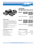
3CP Plunger Pump
3CP1120,3CP1130
3CP1140
3CP1120G
FEATURES
Model 3CP1120 Shown
(Rails and shaft protector sold separately)
Triplex design offers high efficiency and low pulsation.
Durable high pressure seals are lubricated and cooled by pumped
liquid.
Pre-set Lo-Pressure Seals provide secondary protection against
external leaks and require no packing adjustment.
Special high-density, polished, concentric plungers provide a true
wear surface and extended seal life.
Specially formulated seals offer unmatched performance and
extended life.
Optional STHT, FPM and EPDM elastomers for compatibility with
many liquids and temperaturesup to 200°F.
Convenient press in style seal case and interchangeable inlet and
discharge valves for easy servicing
Wet-end easily serviced without entering crankcase.
COMMON SPECIFICATIONS
Inlet Pressure Range .................... Flooded to 70 PSI (Flooded to 4.9 BAR)
Bore ..........................................................................0.709”
(18 mm)
Crankcase Capacity............................................. 12 oz.
(0.35 L)
Standard Liquid Temperature .........................160°F
(71°C)
Above 130°F call CAT PUMPS for inlet conditions and elastomer recommendations.
Inlet Ports (2) ................................................. 1/2” NPTF
(1/2” NPTF)
Discharge Ports (2) ...................................... 3/8” NPTF
(3/8” NPTF)
Pulley Mounting .........................................Either Side
(Either Side)
Shaft Diameter .....................................................0.650”
(16.5 mm)
Weight .............................................................. 14.84 lbs.
(6.7 kg)
Dimensions ........................................9.1 x 8.78 x 5.47” (231 x 223 x 139 mm)
All High Pressure Systems require a primary pressure regulating device (i.e. regulator,
unloader) and a secondary pressure relief device (i.e. pop-off valve, relief valve). Failure
to install such relief devices could result in personal injury or damage to pump or
property. CAT PUMPS does not assume any liability or responsibility for the operation
of a customer’s high pressure system.
Read all CAUTIONS and WARNINGS before commencing service or operation of any
high pressure system. The CAUTIONS and WARNINGS are included in each service
manual and with each Accessory Data sheet. CAUTIONS and WARNINGS can also be
viewed online at www.catpumps.com/cautions-warnings or can be requested directly
from CAT PUMPS.
SPECIFICATIONS
U.S. Measure
Metric Measure
Flow ......................................................................4.2 gpm
Pressure Range ...................................100 to 2200 psi
RPM....................................................................1725 rpm
Stroke.......................................................................0.500”
(16 lpm)
(7 to 155 bar)
(1725 rpm)
(12.7 mm)
MODEL 3CP1120 DIRECT DRIVE
MODEL 3CP1120G GEARBOX (2.55 : 1 RATIO)
Flow ......................................................................3.5 gpm
Pressure Range ...................................100 to 2200 psi
Pump RPM ......................................................1420 rpm
Engine RPM ....................................................3600 rpm
Stroke.......................................................................0.500”
(13.2 lpm)
(7 to 155 bar)
(1420 rpm)
(3600 rpm)
(12.7 mm)
MODEL 3CP1130 DIRECT DRIVE
Flow ......................................................................2.4 gpm
Pressure Range ...................................100 to 2200 psi
RPM....................................................................1725 rpm
Stroke.......................................................................0.276”
(9 lpm)
(7 to 155 bar)
(1725 rpm)
(7 mm)
MODEL 3CP1140 DIRECT DRIVE
Flow ......................................................................3.6 gpm
Pressure Range ...................................100 to 2200 psi
RPM....................................................................1725 rpm
Stroke.......................................................................0.433”
(13.6 lpm)
(7 to 155 bar)
(1725 rpm)
(11 mm)
ELECTRIC HORSEPOWER REQUIREMENTS
MODELS
3CP1120
3CP1130
3CP1140
3CP1120G
FLOW
PRESSURE
MOTOR PULLEY SIZE
psi
psi
psi
psi
1200 1500 2000 2200 rpm
bar bar bar bar
85 105 140 155
35
4.3
5.8
6.3 1725
2.9
3.6
4.8
5.3 1531
2.5
3.1
4.2
4.5 1313
1.9
2.4
3.2
3.6 1725
Using 1750 rpm Motor
5.0” Pump Pulley O.D.
Pulley
O.D.
Direct Drive
4.4
3.8
Direct Drive
gpm
4.2
3.5
3.0
2.4
lpm
16
13.2
11.4
9
3.6
13.6
3.0
3.7
5.0
5.4
1725
Direct Drive
3.5
13.2
2.9
3.6
4.8
5.3
1420
Gearbox
DETERMINING
THE PUMP R.P.M.
DETERMINING
THE REQUIRED H.P.
DETERMINING
MOTOR PULLEY SIZE
Rated gpm
Rated rpm
gpm x psi
1460
Motor Pulley O.D.
Pump rpm
=
=
=
“Desired” gpm
“Desired” rpm
Electric Brake
H. P. Required
Pump Pulley O.D.
Motor rpm
See complete Drive Packages [Inclds: Pulleys, Belts, Hubs, Key] Tech Bulletin 003.
Refer to pump Service Manual for repair procedure and additional technical information.
Pressure Sensitive
Regulating Unloader
Models
FEATURES
Maintains full system pressure while running
in by-pass without full load on pump.
Offers pump protection against pressure
fluctuations and system changes.
Minimum pressure fluctuations with alternating
use of multiple guns.
Adjusting cap permits easy adjustments of
pressure.
All High Pressure Systems require a primary pressure regulating device (i.e. regulator, unloader)
and a secondary pressure relief device (i.e. pop-off valve, relief valve). Failure to install such relief
devices could result in personal injury or damage to pump or property. CAT PUMPS does not
assume any liability or responsibility for the operation of a customer’s high pressure system.
Read all CAUTIONS and WARNINGS before commencing service or operation of any high
pressure system. The CAUTIONS and WARNINGS are included in each service manual and with
each Data sheet. CAUTIONS and WARNINGS can also be viewed online at
www.catpumps.com/cautions-warnings or can be requested directly from CAT PUMPS.
SPECIFICATIONS
7500S
7600S
U.S. Measure
Metric Measure
MODEL 7500S
Flow Range ...............................0.5-6.0 GPM
(1.89-23.0 L/M)
Pressure Range ....................... 100-2000 PSI
(7-140 BAR)
Weight ................................................14.4 oz
(0.41 kg)
Dimensions ...........................3.0 x 1.0 x 4.25” (76 x 25x 108 mm)
MODEL 7600S
Flow Range ...............................2.0-5.0 GPM
(7.6-19.0 L/M)
Pressure Range ....................... 700-3500 PSI
(48-245 BAR)
Weight ................................................21.6 oz
(0.61 kg)
Dimensions ...........................3.25 x 1.0 x 5.0” (82 x 25x 127 mm)
COMMON SPECIFICATIONS
Max. Temperature ................................ 180°F
Inlet Port .......................................3/8” NPTM
By-Pass Port .................................3/8” NPTF
Outlet Port ....................................3/8” NPTM
(82°C)
(3/8” NPTM)
(3/8” NPTF)
(3/8” NPTM)
For Relief Valve version add .100 to unloader model number.
Read all CAUTIONS and WARNINGS before commencing
service or operation of any high-pressure system
SELECTION
PRESSURE ADJUSTMENT
These are pressure sensitive regulating unloaders, designed for systems
with single or multiple pumps, solenoid (gate) valves, nozzles, standard
or “weep” guns.
1. Setting and adjusting the unloader pressure must be done with the
system “on”.
Note: For multiple pump systems, it is best to use a pressure regulator
not a pressure sensitive regulating unloader.
2. Start the system with unloader backed off to the lowest pressure
setting (counterclockwise direction).
3. Squeeze the trigger and read the pressure on the gauge at the
pump.
These pressure sensitive regulating unloaders should meet both the
desired system flow (combined nozzle flow rate requirement) and the
desired system pressure.
Note: Do not read the pressure at the gun or nozzle.
Note: Operation below the minimum flow of the unloader causes the
unloader to cycle. Operation above the maximum flow of the unloader
causes premature unloader wear, cycling and prevents attaining desired
system pressure
5. Squeeze the trigger and read the pressure.
INSTALLATION
7. Once the desired system pressure is reached, stop turning the hex
adjusting cap.
These unloaders operate properly when mounted in any direction,
however, it is preferred to keep the plumbing to a minimum and the hex
adjusting cap easily accessible. The best mounting location is directly
onto the pump discharge manifold head.
Note: Pressure is not set at the factory
The inlet connection is a 3/8” NPTM sized port located on the back side
of the unloader. An arrow is cast into the body indicating the direction
of flow through the valve. Liquid from the discharge of the pump goes
through this connection.
The discharge connection is a 3/8” NPTM sized port located on the
front side (hex end). An arrow and the word OUT is cast into the body
indicating the direction of flow. Plumbing for spray guns, solenoid (gate)
valves or nozzles is connected here.
The by-pass connection is a 3/8” NPTF sized port located on the
bottom. By-Pass liquid is directed out of this port and can be routed to a
reservoir (preferred method), or to a drain or to the pump inlet.
OPERATION
These pressure sensitive regulating unloaders hold established
system pressure in the discharge line when the trigger gun is closed or
solenoid (gate) valve is closed or the nozzle is clogged, thus by-passing
all unrequired flow. Squeezing the trigger gun or opening the solenoid
(gate) valve will close off the by-pass and return to established system
pressure without delay.
TYPICAL UNLOADER INSTALLATION
4. If more pressure is desired, release the trigger, turn hex adjusting
cap one quarter turn in clockwise direction.
6. Repeat this process until desired system pressure is attained.
Caution: A minimum by-pass flow of 5% of the unloader rated flow
capacity is required for proper unloader performance. If the entire out
is directed through the nozzle (zero by-pass) the “cushioning” feature
of the by-pass liquid is eliminated and the unloader can malfunction or
wear prematurely.
8. If desired system pressure cannot be reached, review
TROUBLESHOOTING chart.
9. When servicing existing systems, follow adjustment procedures as
stated above for new unloaders.
Note: Do not adjust unloader pressure setting to compensate for a worn
nozzle. Check the nozzle as part of the regular maintenance and replace
if worn.
Note: A secondary pressure relief device (i.e. pop-off valve) should
be used along with this pressure sensitive regulating unloader. Final
adjustment for the relief valve should relieve at 200 psi above the
system operating pressure.
Read all CAUTIONS and WARNINGS before commencing
service or operation of any high-pressure system
SERVICING
16. Examine piston retainer for wear. Examine o-rings and back-upring for cuts or wear and replace as needed.
Disassembly:
1. Disconnect by-pass, discharge and inlet plumbing from
unloader.
2. Remove unloader from pump.
3. Secure body of unloader in a vise with hex adjusting cap facing
up.
4. Model 7500S: Remove discharge fitting and o-ring, spring, check
valve and o-ring.
Model 7600S: Remove discharge fitting and o-ring, spring, check
valve and o-ring, collar, check valve seat and o-ring.
Note: Seat for check valve will remain in the unloader. Exercise caution
in removing to avoid damage to unloader walls and seat.
5. Examine check valve, check valve seat, collar and discharge
fitting for wear, spring for wear or fatigue and o-rings for cuts or
wear and replace as needed.
Note: While the discharge fitting is removed, inspect sealing area where
the check valve makes contact within the internal body of the unloader
for grooves, pitting and wear. If damage is found, stop the repair and
replace with complete new unloader. If not, proceed with disassembly.
6. If supplied with a lock nut, the lock nut does not need to be
removed. Turn lock nut down towards unloader body.
7. Remove hex adjusting cap by turning in a counterclockwise
direction.
8. Remove spring and spring retainer.
9. Examine spring and spring retainer for scale build up, fatigue or
wear and replace as needed.
10. Remove by-pass fitting with o-ring from bottom port.
11. Remove seat with o-ring from the male threaded side of by-pass
fitting.
12. Examine seat for scale build up, scoring and wear and replace as
needed. Examine o-ring for cuts or wear and replace as needed.
13. Removal of piston stem and valve/ball assembly requires the use
of a small hex socket and screwdriver. Insert screwdriver from
the top and place in slotted head of piston stem. Insert small
hex socket into bottom port and secure valve/ball assembly.
Unthread by turning in a counterclockwise direction.
14. Examine piston stem and valve/ball assembly for scale build up,
scoring, pitting and wear and replace as needed. Examine o-rings
and backup ring for cuts or wear and replace as needed.
15. Remove piston retainer with o-rings and backup rings by turning
in a counterclockwise direction.
Reassembly:
1. Lubricate and install small body back-up-ring and then body
o-ring into unloader body.
2. Lubricate and install o-ring over threads of piston retainer.
3. Carefully hand thread piston retainer with small diameter hole
facing down into unloader body and tighten with a wrench.
4. Lubricate and install o-ring over piston stem head and then
backup-ring into groove of piston stem.
5. Apply Loctite® 242® to the last few threads of the piston stem.
6. Insert piston stem from the top through the piston retainer until
seated.
7. Using the same tools in removing the piston stem and valve/
ball assembly, place valve/ball assembly into hex socket tool
with ball surface facing down into socket. Place screwdriver tip
into piston stem slotted head. Thread piston stem into valve/ball
assembly.
8. Place by-pass fitting on flat surface with male threads facing up.
9. Lubricate and install o-ring onto seat. Press seat into by-pass
fitting. Hand thread by-pass fitting into lower port of unloader
body and tighten with wrench.
10. Lubricate and install o-ring on discharge fitting.
11. Model 7500S: Insert spring into discharge filling, then insert
check valve with small step end into spring. Hand thread into
unloader body and tighten with wrench.
Model 7600S: Lubricate and install o-ring onto check valve seat.
Insert check valve seat with o-ring into unloader body. Install
collar with notches facing in towards check valve seat. Insert
spring into discharge fitting, then insert check valve with small
step end into spring. Hand thread into unloader body and tighten
with wrench.
12. Place spring retainer on top of piston stem.
13. Place spring on to spring retainer.
14. Thread hex adjusting cap onto piston retainer.
15. Remove unloader from vise.
16. Re-install unloader onto pump.
17. Reconnect by-pass, discharge and inlet plumbing to unloader.
18. Proceed to PRESSURE ADJUSTMENT.
TROUBLESHOOTING
PRESSURE READING
Unloader cycles
Check for leak downstream of unloader.
Worn O-ring or check valve.
Air in system, poor connection.
O-ring in gun worn.
Insufficient flow through unloader.
Liquid leaking from
bottom fitting
O-ring for fitting cut or worn.
O-ring for seat cut or worn.
Liquid leaking from
middle
O-ring for piston worn or cut.
O-rings for piston stem worn or cut.
Unloader will not come
up to pressure
Not properly sized for system pressure.
Foreign material in unloader. Clean filter.
Piston stem O-rings worn.
Nozzle worn.
Insufficient flow to pump.
Extreme pressure
spikes
Adjusting nut turned completely
into unloader.
Restricted by-pass or no by-pass.
System flow exceeds unloader rating.
Filtration
Clean filter on regular schedule to
avoid cavitation.
Loctite® and 242® are registered trademarks of the Henkel
Corporation.
Approximate
Pressure Reading
at Gauge
Gauge
Between
Pump/Unloader
Gauge
Between
Unloader/Gun-Nozzle-Valve
System in operation
(gun open)
system pressure
system pressure
System in by-pass
(all guns,valves closed)
low pressure
0-150 PSI
system pressure
+200 PSI
EXPLODED VIEW
7500S Unloader
EXPLODED VIEW
7600S Unloader
PARTS LIST
PARTS LIST
ITEM
P/N MATL DESCRIPTION
QTY.
402 540081 BB
Cap, Hex Adjusting
1
403
31047 BB
Nut, Lock (M18 x 1)
1
408
32094 STZP R Spring, Pressure
1
410 107672 BB
Retainer, Spring
1
412
45694 S
Stem, Piston (M5)
1
414
20184 PTFE
Back-up-Ring, Piston Stem
1
415
14190 NBR
O-Ring, Piston Stem - 70D
1
14161 FPM
O-Ring, Piston Stem - 70D
1
425 107673 BB
Retainer, Piston
1
428
13969 NBR
O-Ring, Piston Retainer - 70D
1
14320 FPM
O-Ring, Piston Retainer - 70D
1
429
14759 NBR
O-Ring, Body
1
14160 FPM
O-Ring, Body - 80D
1
430 107675 PTFE
Back-up-Ring, Body
1
435
45696 BB
Valve and Ball Assembly (M5)
1
436 107680 S
Seat
1
437
13963 NBR
O-Ring, Seat - 70D
1
14303 FPM
O-Ring, Seat - 70D
1
440
— BB
Body
1
442
13969 NBR
O-Ring, By-Pass Fitting - 70D
1
14320 FPM
O-Ring, By-Pass Fitting - 70D
1
443 541060 BB
Valve, Check w/O-Ring
1
444
45924 S
Spring
1
446
13969 NBR
O-Ring, Discharge Fitting - 70D
1
14320 FPM
O-Ring, Discharge Fitting - 70D
1
455
45695 BB
Fitting, By-Pass (3/8” NPTF)
1
460 107681 BB
Fitting, Discharge (3/8” NPTM)
1
468
32097 NBR
Kit, O-Ring (Inclds: 414,415, 428 - 430, 437, 442, 446)
1
31627 FPM
Kit, O-Ring (Inclds: 414,415, 428 - 430, 437, 442, 446)
1
Italics are optional items. R Components comply with RoHS Directive.
MATERIAL CODES (Not Part of Part Number): BB=Brass FPM=Fluorocarbon
NBR=Medium Nitrile (Buna-N) PTFE=Pure Polytetrafluoroethylene S=304SS
STZP=Steel/Zinc Plated
ITEM
P/N MATL
402
45197 BB
404
45201 BB
408
45198 ZP
410
45199 BB
412
45694 S
414
20184 PTFE
415
14190 NBR
425
45200 BB
428
26133 NBR
429
14759 NBR
430 107675 PTFE
435
45716 S
436 107680 S
437
26127 NBR
438
45206 S
439
45205 BB
440
— BB
441
13963 NBR
442
26133 NBR
443
35203 BB
444
45924 S
446
26133 NBR
455
45695 BB
460 107681 BB
468
32098 NBR
DESCRIPTION
QTY.
Cap, Hex Adjusting
1
Nut, Lock (M25x1)
1
Spring, Pressure
1
Retainer, Spring
1
Stem, Piston (M5)
1
Back-up-Ring, Piston Stem
1
O-Ring, Piston Stem - 70D
1
Retainer, Piston
1
O-Ring, Piston Guide - 80D
1
O-Ring, Body
1
Back-up-Ring, Body
1
Valve and Ball Assembly (M5)
1
Seat
1
O-Ring, Seat
1
Seat, C-Valve
1
Collar
1
Body
1
O-Ring, Seat - 70D
1
O-Ring, Adapter - 80D
1
Valve, Check w/O-Ring
1
Spring
1
O-Ring, Discharge Fitting - 80D
1
Fitting, By-Pass (3/8” NPTF)
1
Fitting, Discharge (3/8” NPTM)
1
Kit, O-Ring (Inclds: 414,415,428,429,430,437,441,442,446) 1
Italics are optional items.
MATERIAL CODES (Not Part of Part Number):
BB=Brass NBR=Medium Nitrile (Buna-N) PTFE=Pure Polytetrafluoroethylene
S=304SS ZP=Zinc Plated
CAT PUMPS (U.K.) LTD.
World Headquarters
CAT PUMPS
1681 - 94th Lane N.E. Minneapolis, MN 55449-4324
Phone (763) 780-5440 — FAX (763) 780-2958
N.V. CAT PUMPS INTERNATIONAL S.A
The Pumps with Nine Lives
International Inquiries
FAX (763) 785-4329
“Original Instructions”
CAT PUMPS DEUTSCHLAND GmbH
PARTS LIST
ITEM
2
5
8
10
11
15
20
25
32
33
37
38
40
48
49
50
51
53
64
65
70
75
88
90
98
99
100
106
120
121
125
139
163
164
166
167
168
172
174
185
188
196
250
260
265
270
283
299
300
310
350
500
—
P/N
MATL
DESCRIPTION
30047
92519
125824
46901
48259
14028
43222
14480
48730
46927
46994
46991
48484
48257
46798
14179
92241
44428
92519
125824
25625
23170
46939
14041
48644
46615
48459
46839
43900
45697
46976
46730
48394
† 48201
46541
43243
44926
76243
46625
13976
48522
43245
44925
46652
43448
17547
11685
45790
43723
43750
44565
17615
15855
46756
46616
126512
22187
118672
30612
30641
30246
34334
76334
814841
33983
33257
31983
76526
76983
33062
33258
30696
8075
6107
STL
STZP
STCP R
AL
AL
NBR
NBR
STL
TNM
FCM
FCM
FCM
FCM
FCM
RTP
NBR
—
NBR
STZP
STCP R
STCP
NBR
AL
NBR
AL
CM
BBNP
NBR
S
S
CC
NBR
FPM
SS
PVDF
NBR
FPM
ST
BB
NBR
FPM
SNG
FPM
HT
BB
NBR
FPM
S
S
S
PVDF
NBR
FPM
BB
FBB
STCP R
BBCP
STCP
STZP
—
STL
—
—
FBB
NBR
FPM
HT
STHT
STHT
NBR
FPM
STZP
—
—
Key (M5x5x24)
Screw, HHC Sems (M6x16)
Screw, HHC Sems (M6x16)
Cover, Bearing
Cover, Blind - 3CP1120G
O-Ring, Bearing Cover - 70D
Seal, Oil, Crankshaft - 70D
Bearing, Ball
Rod, Connecting, Assembly [5/01]
Crankshaft, Dual End - 3CP1120 (M12.7)
Crankshaft, Dual End - 3CP1130 (M7)
Crankshaft, Dual End - 3CP1140 (M11)
Crankshaft, Single End - 3CP1140CS, (M11)
Crankshaft, Single End - 3CP1120G (M12.7)
Cap, Oil Filler
O-Ring, Oil Filler Cap - 70D
Gauge, Oil, Bubble w/Gasket
Gasket, Flat, Oil Gauge - 80D
Screw, HHC Sems (M6x16)
Screw, HHC Sems (M6x16)
Plug, Drain (1/4”x19BSP)
O-Ring, Drain Plug - 70D
Cover, Rear
O-Ring, Rear Cover - 70D
Crankcase
Pin, Crosshead
Rod, Plunger
Seal, Oil, Crankcase
Slinger, Barrier
Washer, Keyhole (M18 x 10)
Plunger (M18x43)
Washer, Seal - 90D
Washer, Seal - 90D
Retainer, Plunger w/Stud (M6)
Retainer, Seal
Seal, LPS w/S-Spg
Seal, LPS w/SS-Spg
Seal, LPS w/S-Spg
Case, Seal (See Tech Bulletin #110)
O-Ring, Seal Case - 70D
O-Ring, Seal Case
Seal, HPS w/S
Seal, HPS w/SS
Seal, HPS “Hi-Temp”, 2-Pc w/S-Support
Plug, Inlet (1/2”NPT)
O-Ring, Seat - 85D
O-Ring, Seat - 85D
Seat
Valve
Spring
Retainer, Spring
O-Ring, Valve Plug - 75D
O-Ring, Valve Plug - 70D
Plug, Valve
Manifold, Head
Screw, HSH (M8x65)
Plug, Discharge (3/8”NPT)
Protector, Shaft
Mount, Rail Assy
Mount, Assy (Inclds: 30612, 30032, 30047, 118672)
Assy, Pulley & Key (Inclds: 30032, 30047) (See Tech Bulletin 003)
Kit, Oil Drain (3/8” x 24”) (See individual Data Sheet)
Kit, Oil Indicator (3/8” x 24”) (See individual Data Sheet)
Head, Complete
Kit, Seal (Inclds: 98, 106, 121, 125)
Kit, Seal (Inclds: 98, 106, 121, 125)
Kit, Seal (Inclds: 98, 106, 121, 125)
Kit, Seal (Inclds: 98, 106, 120, 121, 125) Prior to 4/10
Kit, Seal (Inclds: 98, 106, 121, 125) After 4/10
Kit, Valve (Inclds: 163, 164, 166, 167, 168, 172)
Kit, Valve (Inclds: 163, 164, 166, 167, 168, 172)
Plier, Reverse
Gearbox (See Individual Data Sheet)
Oil, Bottle (21 oz.) ISO 68 Hydraulic
(Fill to specified crankcase capacity prior to start-up)
QTY
1
8
8
2
1
2
1/2
2
3
1
1
1
1
1
1
1
1
1
4
4
1
1
1
1
1
3
3
3
3
3
3
3
3
3
3
3
3
3
3
3
3
3
3
3
1
6
6
6
6
6
6
6
6
6
1
8
1
1
1
1
1
1
1
1
1
1
1
1
1
2
2
1
1
1
Bold print part numbers are unique to a particular pump model. Italics are optional items. [ ] Date of latest production change.
† Production parts are different than repair parts. R Components comply with RoHS Directive.
View Tech Bulletins 002, 003, 024, 036, 064, 073, 074, 077, 083, and 110 for additional information.
For motorized versions see BD motor data sheet. For Gearbox version see 8075 data sheet.
MATERIAL CODES (Not Part of Part Number): AL=Aluminum BB=Brass BBCP=Brass/Chrome Plated BBNP=Brass Nickel Plated CC=Ceramic
CM=Chrome-moly FBB=Forged Brass FCM=Forged Chrome-Moly FPM=Fluorocarbon HT=Hi-Temp (EPDM Alternative) NBR=Medium Nitrile (Buna-N)
PVDF=Polyvinylidene Fluoride RTP=Reinforced Composite S=304SS SNG=Special Blend (Buna) ST=Polyetheretherketon
STHT=Special PTFE High Temp STL=Steel STCP=Steel/Chrome Plated STZP=Steel/Zinc Plated TNM=Special High Strength
EXPLODED VIEW
Models
3CP1120, 3CP1120G,
3CP1130, 3CP1140
February 2011
Models 3CP1120, 3CP1120G, 3CP1130, 3CP1140
4
3
5
1
4
1 Special concentric, high-density, polished,
solid ceramic plungers provide a true
wear surface and extended seal life.
2 Manifolds are a high tensile strength
forged brass for long term, continuous duty.
3 100% wet seal design adds to service life
by allowing pumped liquids to cool and
lubricate on both sides of the seals.
4 Stainless steel valves, seats and springs
provide corrosion-resistance, ultimate
seating and extended life.
2
5 Specially formulated, Cat Pump exclusive,
Hi-Pressure Seals offer unmatched performance and seal life.
CAT PUMPS
1681 - 94TH LANE N.E. MINNEAPOLIS, MN 55449-4324
PHONE (763) 780-5440 — FAX (763) 780-2958
e-mail: [email protected]
www.catpumps.com
For International Inquiries go to www.catpumps.com and navigate to the “Contact Us” link.
PN 993101 Rev G 2/11 11145


![DTF-7500S 機能追加のお知らせ [PDF:76.1KB]](http://vs1.manualzilla.com/store/data/006673767_2-d94886004dd4730bddb55701cf046dda-150x150.png)
