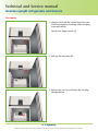
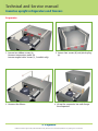
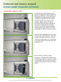
1
Technical and Service manual Inventus upright refrigerators and freezers C&F Rev. 201405 Technical and Service manual Inventus upright refrigerators and freezers Contents User manual - Control unit XW70K and D50K 4 Wiring diagram C 14 Wiring diagram F 15 Troubleshooting 16 Fan motor 20 Evaporator 21 Cleaning the condenser filter 22 Probes, P1 temperature probe 23 Probes, P2 defrost probe 24 Probes, P3 condenser probe 24 How to change the hinging of the solid door 26 EC-declaration of conformity for electrical equipment 30 2 Porkka reserves the right to make product alterations at any time and can not be held responsible for any printing errors or omissions. Technical and Service manual Inventus upright refrigerators and freezers 3 Porkka reserves the right to make product alterations at any time and can not be held responsible for any printing errors or omissions. Technical and Service manual Inventus upright refrigerators and freezers User manual - Control unit XW70K AND D50K 3.4.2 Timed activation of the fans when the compressor is off. XW70K AND D50K 1 When FnC=C-n or C-Y (fans in parallel to the compressor), the fans will be able to carry out on and off cycles even if the compressor is switched off. The on and off interval of time follow the Fon and FoF parameters. When the compressor is stopped the fans will go on working for the Fon time. On the other side, with Fon=0 the fans will stay always off when the compressor is off. GENERAL WARNING 1.1 PLEASE READ BEFORE USING THIS MANUAL 4 By means of the parameter oA4 (28-29) it’s possible to configure the functions of the TRIAC output, as described in the following paragraphs: This manual is part of the product and should be kept near the instrument for easy and quick reference. The instrument shall not be used for purposes different from those described hereunder. It cannot be used as a safety device. Check the application limits before proceeding. 4.1 ON –OFF OUTPUT (DEAFALUT SETTING OA4 = ONF) By setting oA4 =onF, the TRIAC will operate as “on-off”: it will be activated when the controller is switched on and it will be switched off when the controller is in stand-by status. 1.2 SAFETY PRECAUTIONS 2 4.2 LIGHT OUTPUT (OA4 = LIG) Check the supply voltage is correct before connecting the instrument. Do not expose to water or moisture: use the controller only within the operating limits avoiding sudden temperature changes with high atmospheric humidity to prevent formation of condensation Warning: disconnect all electrical connections before any kind of maintenance. Fit the probe where it is not accessible by the End User. The instrument must not be opened. In case of failure or faulty operation send the instrument back to the distributor or to “Dixell S.r.l.” (see address) with a detailed description of the fault. Consider the maximum current which can be applied to each relay (see Technical Data). Ensure that the wires for probes, loads and the power supply are separated and far enough from each other, without crossing or intertwining. In case of applications in industrial environments, the use of mains filters (our mod. FT1) in parallel with inductive loads could be useful. Dixell Srl reserves the right to change the composition of its products, even without notice, ensuring the same and unchanged functionality. By setting oA4=Lig the TRIAC will work as light, it is switched on and off by the light button on the keyboard and is affected by status of the digital input when i1F=dor. The parameter LHt (Light timer) sets the time the light will stay on after pressing the light switch on the keyboard. Every time the key is pushed the timer is re-loaded. 4.3 SECOND COMPRESSOR MANAGEMENT (OA4 = CP2) By setting oA4 =CP2, the correspondent TRIAC will operate as “second compressor”. It will be activated in parallel with the first compressor, with a possible delay set in the AC1 parameter (seconds). Both the compressors are switched off at the same time. 4.4 AUXILIARY OUTPUT (OA4 = AUS) By setting oA4 =AUS, the TRIAC will work as auxiliary thermostat (ex. anti condensing heater). Parameters involved: ACH (cL, Ht): Kind of regulation for the auxiliary output : Ht = heating / CL = cooling; SAA (-50÷150) Set point for auxiliary output SHy (0÷25.5°C) Differential for auxiliary output. With ACH = CL: aux output cut in is SAA+SHy, cut out SAA. With ACH = Ht: aux output cut in is SAA-SHy, cut out SAA. ArP (nP, P1, P2, P3, P4) Probe for auxiliary output Sdd (n, Y) Auxiliary output working during defrost GENERAL DESCRIPTION Model XW70K is microprocessor based controller suitable for applications on medium or low temperature refrigerating units. It has to be connected by means of a two-wire shielded twisted cable ( 1mm) at a distance of up to 30 meters to the keyboard T620T or T620 or V620 or CX620. It is provided with four relay outputs to control compressor, defrost - which can be either electrical or hot gas - the evaporator fans and light. It is also provided with 4 NTC or PTC probe inputs, one for temperature control, one to control the defrost end temperature of the evaporator and the third and fourth to control condenser temperature or to display another temperature. The HOT KEY output allows to connect the unit, by means of the external module XJ485-CX, to a network line ModBUS-RTU compatible such as the dIXEL monitoring units of X-WEB family. It allows to program the controller by means the HOT KEY programming keyboard. The instrument is fully configurable through special parameters that can be easily programmed through the keyboard. 3 SPECIAL FUNCTIONS 4.5 ALARM OUTPUT (OA4 = ALR) By setting oA4 = ALr the correspondent output will work as alarm, it is switched on when an alarm happens. Parameters involved: tbA (n, y) Alarm output silencing AoP (cL; oP) Alarm output polarity 4.6 NEUTRAL ZONE (OA4 = DB) CONTROLLING LOADS By setting oA4 =db the controller will perform a “neutral zone” regulation. The heating element has to be connected to the correspondent relay. If the temperature increases and reaches set point plus differential (HY) the compressor is started and then turned off when the temperature reaches the set point value again. If the temperature decreases and reaches the set point minus differential (HY) the output (heater) is switched on and then turned OFF when the temperature reaches again the set point. 3.1 THE COMPRESSOR The regulation is performed according to the temperature measured by the thermostat probe with a positive differential from the set point: if the temperature increases and reaches set point plus differential the compressor is started and then turned off when the temperature reaches the set point value again. In case of fault in the thermostat probe the start and stop of the compressor are timed through parameters Con and CoF. The relay of the second compressor is activated in parallel with the relay of the first compressor, with a possible delay set in the AC1 parameter. Both the compressors are switched off at the same time. 3.2 FAST FREEZING When defrost is not in progress, it can be activated by holding the UP key pressed for about 3 sec. The compressor operates to maintain the CCS set point for the time set through the CCt parameter. The cycle can be terminated before the end of the set time using the same activation key UP for 3 sec. 3.3 DEFROST Two defrost modes are available through the “tdF” parameter: defrost through electrical heater (tdF = EL) and hot gas defrost (tdF = in). Other parameters are used to control the interval between defrost cycles (IdF), its maximum length (MdF) and two defrost modes: timed or controlled by the evaporator’s probe (P2P). Two defrost modes are available through the tdF parameter: defrost through electrical heater (tdF = EL) and hot gas defrost (tdF = in). A defrost starts after elapsing the idF time. Other parameters are used to control defrost cycles: its maximum length (MdF) and two defrost modes: timed or controlled by the evaporator’s probe. At the end of defrost dripping time is started, its length is set in the Fdt parameter. With Fdt=0 the dripping time is disabled. 3.4 CONTROL OF EVAPORATOR FANS The fan control mode is selected by means of the FnC parameter: FnC = C_n: fans will switch ON and OFF with the compressor and not run during defrost; FnC = o_n fans will run even if the compressor is off, and not run during defrost; After defrost, there is a timed fan delay allowing for drip time, set by means of the Fnd parameter. FnC = C_Y fans will switch ON and OFF with the compressor and run during defrost; FnC = o_Y fans will run continuously also during defrost. An additional parameter FSt provides the setting of temperature, detected by the evaporator probe, above which the fans are always OFF. This is used to make sure circulation of air only if his temperature is lower than set in FSt. 3.4.1 Forced activation for fans This function, managed by the FCt parameter, is designed to avoid short cycles of fans, that could happen when the controller is switched on or after a defrost, when the room air warms the evaporator. If the difference between the evaporator temperature and the room temperature is higher than the FCt value, the controller will activate the fans. This function is disabled if FCt=0. 1598027800 XW70K GB PKK R1.0 10.12.2013doc.docx XW70K 1/6 4 Porkka reserves the right to make product alterations at any time and can not be held responsible for any printing errors or omissions. Technical and Service manual Inventus upright refrigerators and freezers User manual - Control unit XW70K AND D50K 5 KEYBOARD °C/°F 6 ON Light on ON ON Auxiliary relay on (CX620 only) Measurement unit (CX620 only) CONTROLLER INTERFACE 6.1 HOW TO SEE THE MIN TEMPERATURE 1. 2. 3. Press and release the DOWN key. The “Lo” message will be displayed followed by the minimum temperature recorded. By pressing the DOWN key or waiting for 5 sec the normal display will be restored. 6.2 HOW TO SEE THE MAX TEMPERATURE 1. 2. 3. Press and release the UP key. The “Hi” message will be displayed followed by the maximum temperature recorded. By pressing the UP key or waiting for 5 sec the normal display will be restored. 6.3 HOW TO RESET THE MAX AND MIN TEMPERATURE RECORDED To reset the stored temperature, when max or min temperature is displayed: 1. Press SET key until “rST” label starts blinking. Note: after the installation remember to RESET the temperature stored. 6.4 HOW TO SEE AND MODIFY THE SET POINT 1. 2. 3. Push and immediately release the SET key: the display will show the Set point value; To change the SEt value, push the UP or DOWN arrows within 10 sec. To memorise the new set point value push the SET key again or wait for 10 sec. 6.5 TO START A MANUAL DEFROST 1. Push the DEF key for more than 2 sec and a manual defrost will start. 6.6 TO ENTER IN PARAMETERS LIST “PR1” To enter the parameter list “Pr1” (user accessible parameters) operate as follows: 1. Enter the Programming mode by pressing the Set and DOWN key start blinking). for few seconds ( and 2. The instrument will show the first parameter present in “Pr1” + 6.7 THE HIDDEN MENU In the hidden menu there are all the parameters of the instrument. To display and modify target set point; in programming mode it selects a parameter or confirm an operation. By holding it pressed for 3 sec when max or min temperature is displayed it will be erased. (UP) To see the max stored temperature; in programming mode it browses the parameter codes or increases the displayed value. By holding it pressed for 3s the fast freezing cycle is started. (DOWN) To see the min stored temperature; in programming mode it browses the parameter codes or decreases the displayed value. 6.7.1 ENTERING THE HIDDEN MENU 1. Enter the Programming mode by pressing the SET+DOWN keys for 3 sec (the “°C” or “°F” LED will start blinking). 2. Release the keys and then push again the SET+DOWN keys more than 7 sec. The “Pr2” label will be displayed immediately, followed from the HY parameter. NOW THE HIDDEN MENU IS DISPLAYED 3. Select the required parameter. 4. Press SET key to display its actual value 5. Use UP or DOWN keys to change its value. 6. Press SET to store the new value and move to the following parameter. To exit: Press SET+UP or wait for 15 sec without pressing any key. (DEF) By holding it pressed for 3 sec the defrost is started. NOTE1: if no parameter is present in the “Pr1” level, after the first 3 sec the “noP” message will be displayed. Keep SET+DOWN keys pushed till the “Pr2” message will be displayed. (ONOFF) Switch ON and OFF the instrument. NOTE2: the new set value will be stored even if the procedure is exited by waiting for the time-out to expire. 6.7.2 HOW TO: MOVE A PARAMETER FROM THE HIDDEN MENU TO THE FIRST LEVEL AND VICEVERSA. KEY COMBINATIONS + To lock and unlock the keyboard. + To enter the programming mode. + To exit the programming mode. Each parameter present in the HIDDEN MENU can be moved or put into “THE FIRST LEVEL” (user level) by pressing SET+DOWN keys. In HIDDEN MENU, if a parameter is present also in the First Level (Pr1), the decimal point will be lit. 6.7.3 HOW TO CHANGE THE PARAMETER VALUE 1. Enter the Programming mode. 2. Select the required parameter with UP or DOWN. 3. Press the “SET” key to display its value ( and LED starts blinking). 4. Use UP or DOWN to change its value. 5. Press SET to store the new value and move to the following parameter. To exit: Press SET+UP or wait for 15 sec without pressing any key. NOTE: the new programming is stored even when the procedure is exited by waiting the time-out. 5.1 USE OF LEDS Each LED function is described in the following table. LED MODE ON FLASHING ON FLASHING ON FLASHING ON ON ON ON 6.8 HOW TO LOCK THE KEYBOARD (MANUALLY) Function The compressor is running - Programming Phase (flashing with LED - Anti-short cycle delay enabled The fan is running Programming Phase (flashing with LED The defrost is enabled Drip time in progress 1. ) Keep the UP and DOWN keys pressed together for more than 3 sec the UP and DOWN keys. The “PoF” message will be displayed and the keyboard is locked. At this point it is only possible the viewing of the set point or the MAX o Min temperature stored and to switch ON and OFF the light, the auxiliary output and the instrument. 2. + ) TO UNLOCK THE KEYBOARD Keep the UP and DOWN keys pressed together for more than 3 sec. The Fast Freezing cycle is enabled - ALARM signal - In “Pr2” indicates that the parameter is also present in “Pr1” Continuous cycle is running Energy saving enabled 1598027800 XW70K GB PKK R1.0 10.12.2013doc.docx XW70K 2/6 5 Porkka reserves the right to make product alterations at any time and can not be held responsible for any printing errors or omissions. Technical and Service manual Inventus upright refrigerators and freezers User manual - Control unit XW70K AND D50K dPo dAF 6.9 ON/OFF FUNCTION (STAND BY) By pushing the ON/OFF key, the instrument shows “OFF” for 5 sec. and the ON/OFF LED is switched ON. During the OFF status, all the relays are switched OFF and the regulations are stopped; if a monitoring system is connected, it does not record the instrument data and alarms. When the instrument is in stand by the keyboard displays “oFF”. FANS FnC N.B. During the OFF status the Light and AUX buttons are active. Fnd 6.10 TO SEE THE PROBE VALUES 1. 2. Enter in “Pr1” level. Parameters “dP1”, “dP2”, “dP3” and “dP4” display the value of probes 1, 2, 3 and 4. 7 PARAMETER LIST FCt FSt REGULATION HY LS US ot P2P oE P3P o3 P4P o4 odS AC AC1 rtr CCt CCS Con CoF Fon Differential: (0.1 to 25.5°C; 1 to 45°F) intervention differential for set point. Compressor Cut IN is Set Point + differential (HY). Compressor Cut OUT is when the temperature reaches the set point. Minimum set point: (-55°C to SET; -67°F to SET) sets the minimum value for the set point. Maximum set point: (SET to 150°C; SET to 302°F) set the maximum value for set point. Thermostat probe calibration: (-12.0 to 12.0°C; -21 to 21°F) allows to adjust possible offset of the thermostat probe. Terminals 1-2. Second probe presence: (n; Y) n = not present, the defrost stops by time; Y = present, the defrost stops by temperature. Terminals 2-3 Second probe calibration: (-12.0 to 12.0°C; -21 to 21°F) allows to adjust possible offset of the second probe. Terminals 2-3. Third probe presence (P3): (n; Y) n = not present, Y = present. Terminals 4-5 Third probe calibration (P3): (-12.0 to 12.0°C; -21 to 21°F) allows to adjust possible offset of the third probe. Terminals 4-5 Fourth probe presence: (n; Y) n = Not present; Y = present. Terminals 5-6 Fourth probe calibration: (-12.0 to 12.0°C; -21 to 21°F) allows to adjust possible offset of the fourth probe. Terminals 5-6 Outputs activation delay at start up: (0 to 255min) this function is enabled at the initial start up of the instrument and inhibits any output activation for the period of time set in the parameter. Anti-short cycle delay: (0 to 50min) minimum interval between the compressor stop and the following restart. 2nd compressor delay at start up (0÷255s) Used only with oA3 or oA4 = cP2 Time interval between the switching on of the first compressor and the second one. Percentage of the second and first probe for regulation: (0 to 100; 100=P1, 0=P2) it allows to set the regulation according to the percentage of the first and second probe, as for the following formula (rtr(P1-P2)/100 + P2). Compressor ON time during continuous cycle: (0.0 to 24h00min, res. 10min) allows to set the length of the continuous cycle. Compressor stays on without interruption during CCt time. This is useful, for instance, when the room is filled with new products. Set point for continuous cycle: (-55 to 150°C; -67 to 302°F) it sets the set point used during the continuous cycle. Compressor ON time with faulty probe: (0 to 255min) time during which the compressor is active in case of faulty thermostat probe. With Con=0 compressor is always OFF. Compressor OFF time with faulty probe: (0 to 255min) time during which the compressor is OFF in case of faulty thermostat probe. With CoF=0 compressor is always active. FoF FAP rES rEd dLY dtr ACH SAA SHY ArP Sdd dtE idF MdF dSd dFd dAd Fdt ALP ALC ALU ALL AFH Temperature measurement unit: (°C; °F) °C = Celsius; °F = Fahrenheit. WARNING: When the measurement unit is changed the SET point and the values of the parameters related to the temperature have to be checked and modified (if necessary). Resolution (for °C): (in=1°C; dE=0.1°C) allows decimal point display. Probe display (P1; P2, P3, P4, SET, dtr) it selects which probe is displayed by the controller. P1 = Thermostat probe; P2 = Second probe; P3 = Third probe; P4 = Fourth probe, SET = set point; dtr = percentage of visualization. Display delay: (0 to 20min00s; res. 10s) when the temperature increases, the display is updated of 1°C or 1°F after this time. Percentage of the second and first probe for visualization when Lod=dtr: (0 to 99; 100=P1, 0=P2) if Lod=dtr it allows to set the visualization according to the percentage of the first and second probe, as for the following formula (dtr(P1-P2)/100 + P2). ALd dot dAo Probe selection for alarm: (nP; P1; P2; P3; P4) nP = no probe, the temperature alarms are disabled; P1 = Probe 1 (Thermostat probe); P2 = Probe 2; P3 = Probe 3; P4 = Fourth probe. Temperature alarms configuration: (Ab; rE) Ab = absolute temperature, alarm temperature is given by the ALL or ALU values. rE = temperature alarms are referred to the set point. Temperature alarm is enabled when the temperature exceeds the [SET+ALU] or [SET-ALL] values. MAXIMUM temperature alarm: If ALC=Ab: [ALL to 150.0°C or ALL to 302°F] If ALC=rE: [0.0 to 50.0°C or 0 to 90°F] when this temperature is reached the alarm is enabled, after the ALd delay time. Minimum temperature alarm: If ALC=Ab: [-55°C to ALU; -67 to ALU] If ALC=rE: [0.0 to 50.0°C or 0 to 90°F] when this temperature is reached the alarm is enabled, after the ALd delay time. Differential for temperature alarm recovery: (0.1 to 25.5°C; 1 to 45°F) intervention differential for recovery of temperature alarm. Temperature alarm delay: (0 to 255 min) time interval between the detection of an alarm condition and alarm signalling. Temperature alarm delay, with door open: (0 to 255 min) time interval between the detection of temperature alarm condition and alarm signaling with door open. Exclusion of temperature alarm at start-up: (0.0 to 24h00min, res. 10min) time interval between the detection of the temperature alarm condition after instrument power on and alarm signalling. CONDENSER TEMPERATURE ALARM AP2 AL2 Au2 Defrost type: (EL; in) EL = electrical heater; in = hot gas. Probe selection for defrost termination: (nP; P1; P2; P3; P4) nP = no probe; P1 =thermostat probe; P2 = Second probe; P3 =Third probe; P4 = Fourth Probe Defrost termination temperature: (-55 to 50°C; -67 to 122°F) (enabled only when EdF=Pb) sets the temperature measured by the evaporator probe, which causes the end of defrost. Interval between defrost cycles: (0 to 120hours) determines the interval of time between two defrost cycles. (Maximum) length for defrost: (0 to 255min) when P2P = nP, (not evaporator probe: timed defrost) it sets the defrost duration. When P2P different from nP (defrost end based on temperature) it sets the maximum length for defrost. Start defrost delay: (0 to 99min) this is useful when different defrost start times are necessary to avoid overloading the plant. Temperature displayed during defrost: (rt; it; SEt; dEF) rt = real temperature; it = temperature at defrost start; SEt = set point; dEF = “dEF” label. MAX display delay after defrost: (0 to 255min) sets the maximum time between the end of defrost and the restarting of the real room temperature display. Drip time: (0 to 120min) time interval between reaching defrost termination temperature and the restoring of the control’s normal operation. This time allows the evaporator to eliminate water drops that might have formed due to defrost. 1598027800 XW70K GB PKK R1.0 10.12.2013doc.docx Kind of regulation for auxiliary output: (Ht; CL) Ht = heating; CL = cooling. Set Point for auxiliary output: (-55.0 to 150.0°C; -67 to 302°F) it defines the room temperature set point to switch auxiliary output. Differential for auxiliary output: (0.1 to 25.5°C; 1 to 45°F) intervention differential for auxiliary output set point. ACH=CL, AUX Cut in is [SAA+SHY]; AUX Cut out is SAA. ACH=Ht, AUX Cut in is [SAA–SHY]; AUX Cut out is SAA. Probe selection for auxiliary: (nP; P1; P2; P3; P4) nP = no probe, the auxiliary output is switched only by the digital input; P1 = Probe 1 (Thermostat probe); P2 = Probe 2; P3 = Probe 3; P4 = Probe 4. Auxiliary output off during defrost: (n; Y) n = the auxiliary output operates during defrost. Y = the auxiliary output is switched off during defrost. ALARMS DEFROST tdF dFP Fans operating mode: (C-n; o-n; C-Y; o-Y) C-n = runs with the compressor, OFF during defrost; o-n = continuous mode, OFF during defrost; C-Y = runs with the compressor, ON during defrost; o-Y = continuous mode, ON during defrost. Fans delay after defrost: (0 to 255min) interval between end of defrost and evaporator fans start. Temperature differential to avoid fan short cycles: (0 to 59°C; 0 to 90°F) (N.B.: FCt=0 means function disabled) if the difference of temperature between the evaporator and the room probes is higher than FCt value, the fans will be switched on. Fans stop temperature: (-55 to 50°C; -67 to 122°F) setting of temperature, detected by evaporator probe, above which fans are always OFF. Fan ON time: (0 to 15min) with Fnc=C_n or C_Y, (fan activated in parallel with compressor) it sets the evaporator fan ON cycling time when the compressor is off. With Fon=0 and FoF≠0 the fan are always off, with Fon=0 and FoF=0 the fan are always off. Fan OFF time: (0 to 15min) With FnC=C_n or C_Y, (fan activated in parallel with compressor) it sets the evaporator fan off cycling time when the compressor is off. With Fon=0 and FoF≠0 the fan are always off, with Fon=0 and FoF=0 the fan are always off. Probe selection for fan management: (nP; P1; P2; P3; P4) nP = no probe; P1 =thermostat probe; P2 = Second probe; P3 =Third probe; P4 =Fourth probe. OA4 = AUS: AUXILIARY THERMOSTAT CONFIGURATION (terms. 28-29) DISPLAY CF First defrost after start-up: (n; Y) n = after the idF time, Y = immediately. Defrost delay after continuous cycle: (0.0 to 24h00min, res. 10min) time interval between the end of the fast freezing cycle and the following defrost related to it. AH2 Ad2 dA2 bLL AC2 Probe selection for temperature alarm of condenser: (nP; P1; P2; P3; P4) nP = no probe; P1 = thermostat probe; P2 = second probe; P3 = Third probe; P4 = Fourth probe. Low temperature alarm of condenser: (-55 to 150°C; -67 to 302°F) when this temperature is reached the LA2 alarm is signalled, possibly after the Ad2 delay. High temperature alarm of condenser: (-55 to 150°C; -67 to 302°F) when this temperature is reached the HA2 alarm is signalled, possibly after the Ad2 delay. Differential for temperature condenser alarm recovery: 0.1 to 25.5°C; 1 to 45°F. Condenser temperature alarm delay: (0 to 255 min) time interval between the detection of the condenser alarm condition and alarm signalling. Condenser temperature alarm exclusion at start up: 0.0 to 24h00min, res. 10min. Compressor off with low temperature alarm of condenser: (n; Y) n = compressor keeps on working; Y = compressor is switched off till the alarm is present, in any case regulation restarts after AC time at minimum. Compressor off with high temperature alarm of condenser: (n; Y) n = compressor keeps on working; Y = compressor is switched off till the alarm is present, in any case regulation restarts after AC time at minimum. RELAY OA3 (22-23) CONFIGURATION tbA oA4 Alarm relay silencing (with oAx =ALr): (n; Y) n = silencing disabled: alarm relay stays on till alarm condition lasts. Y = silencing enabled: alarm relay is switched OFF by pressing a key during an alarm. TRIAN output configuration, terminals 28-29: (dEF; FAn; ALr; LiG; AUS; onF; db; dEF2; HES) dEF = defrost; FAn = Fan; ALr = alarm; LiG = light; AUS = Auxiliary relay; onF = always on with instrument on; db = neutral zone; dEF2 = do not select it; HES = night blind. XW70K 3/6 6 Porkka reserves the right to make product alterations at any time and can not be held responsible for any printing errors or omissions. Technical and Service manual Inventus upright refrigerators and freezers User manual - Control unit XW70K AND D50K AoP Alarm relay polarity: (CL; oP) it set if the alarm relay is open or closed when an alarm occurs. CL = terminals closed during an alarm; oP = terminals open during an alarm. 8.6 START DEFROST (I1F = DFR) It starts a defrost if there are the right conditions. After the defrost is finished, the normal regulation will restart only if the digital input is disabled otherwise the instrument will wait until the MdF safety time is expired. DIGITAL INPUT i1P i1F did I2P I2F d2d nPS odC rrd LES HES First digital input polarity: (oP; CL) oP = the digital input is activated by opening the contact; CL = the digital input is activated by closing the contact. First digital input configuration: (EAL; bAL; PAL; dor; dEF; ES; AUS; Htr; FAn; HdF; onF; Sbt) EAL = external alarm: “EA” message is displayed; bAL = serious alarm “CA” message is displayed; PAL = pressure switch alarm, “CA” message is displayed; dor = door switch function; dEF = activation of a defrost cycle; AUS = auxiliary output activation with oA4=AUS; Htr = type of inverting action (cooling or heating); FAn = fan; ES = energy saving; HdF = Holiday defrost (enable only with RTC); onF = to switch the controller off; LHt = to activate the light. Digital input 1 alarm delay: (0 to 255 min) delay between the detection of the external alarm condition and its signalling. When i1F= PAL, it is the interval of time to calculate the number of pressure switch activation. Second digital input polarity: (oP; CL) oP = the digital input is activated by opening the contact; CL = the digital input is activated by closing the contact. Second digital input configuration: (EAL; bAL; PAL; dor; dEF; ES; AUS; Htr; FAn; HdF; onF; Sbt) EAL = external alarm: “EA” message is displayed; bAL = serious alarm “CA” message is displayed; PAL = pressure switch alarm, “CA” message is displayed; dor = door switch function; dEF = activation of a defrost cycle; AUS = auxiliary relay activation with oA3=AUS; Htr = type of inverting action (cooling or heating); FAn = fan; ES = energy saving; HdF = Holiday defrost (enable only with RTC); onF = to switch the controller off; LHt = to activate the light. Digital input 2 alarm delay: (0 to 255 min) delay between the detection of the external alarm condition and its signalling. When i2F= PAL, it is the interval of time to calculate the number of pressure switch activation. Number of pressure switch activation: (0 to 15) Number of activation, during the did or d2d interval, before signalling an alarm event (i1F, i2F=PAL). If the nPS activation during did or d2d time is reached, switch off and on the instrument to restart normal regulation. Compressor status when open door: (no; FAn; CPr;F_C;) no = normal; FAn = normal; CPr = compressor OFF, F_C = compressor OFF. Outputs restart after door open alarm: (n; Y) n = outputs follow the odC parameter. Y = outputs restart with a door open alarm. Light off during Energy Saving status: n; Y. Delta temperature during an Energy Saving cycle: (-30.0 to 30.0°C; -54 to 54°F) it sets the increasing value of the set point [SET+HES] during the Energy Saving cycle. 8.7 KIND OF ACTION: HEATING OR COOLING (I1F = HTR) This function allows to invert the regulation of the controller: from cooling to heating and viceversa. 8.8 ENERGY SAVING (I1F = ES) The Energy Saving function allows to change the set point value as the result of the SET+HES (parameter) sum. This function is enabled until the digital input is activated. 8.9 DIGITAL INPUTS POLARITY The digital input polarity depends on the i1P or i2P parameters: i1P or i2P=CL: the input is activated by closing the contact. i1P or i2P =OP: the input is activated by opening the contact 9 INSTALLATION AND MOUNTING D50K keyboard shall be mounted on vertical panel, and fixed using two columns according to the following dimensions. OTHER Adr PbC onF dP1 dP2 dP3 dP4 rSE rEL Ptb 8 Serial address: (1 to 247) identifies the instrument address when connected to a ModBUS compatible monitoring system. Type of probe: (PtC; ntC) it allows to set the kind of probe used by the instrument: PtC = PTC probe; ntC = NTC probe. On/Off key enabling: (nU; oFF; ES) nU = disabled; oFF = enabled; ES = not set it. Thermostat probe display. Second probe display. Third probe display. Fourth probe display (only for XW60LT models). Real set point: it shows the set point used during the energy saving cycle or during the continuous cycle. Software release for internal use. Parameter table code: readable only. The controller XW70K shall be mounted in a din rail It must be connected to the keyboard by means of a two-wire cable ( 1mm). The temperature range allowed for correct operation is 0 to 60°C. Avoid places subject to strong vibrations, corrosive gases, excessive dirt or humidity. The same recommendations apply to probes. Let the air circulate by the cooling holes. 9.1 XW70K – 8 DIN CASE - DIMENSIONS DIGITAL INPUT The free voltage digital inputs are programmable in different configurations by the i1F or i2F parameters. 8.1 DOOR SWITCH INPUT ( DOR) It signals the door status and the corresponding relay output status through the odC parameter: no = normal (any change); Fan = Fan OFF; CPr = Compressor OFF; F_C = Compressor and fan OFF. Since the door is opened, after the delay time set through parameter did, the door alarm is enabled, the display shows the message “dA” and the regulation restarts is rtr = yES. The alarm stops as soon as the external digital input is disabled again. With the door open, the high and low temperature alarms are disabled. 10 ELECTRICAL CONNECTIONS XW70K is provided with screw terminal blocks to connect cables with a cross section up to 2.5 mm2 for the RS485 (optional) and the keyboard. To connect the other inputs, power supply and relays, XW70K is provided with Faston connections (6.3mm). Heat-resistant cables have to be used. Before connecting cables make sure the power supply complies with the instrument’s requirements. Separate the probe cables from the power supply cables, from the outputs and the power connections. Do not exceed the maximum current allowed on each relay, in case of heavier loads use a suitable external relay. NOTE: the maximum current allowed for all the loads is 20A. 8.2 GENERIC ALARM ( EAL) As soon as the digital input is activated the unit will wait for did time delay before signalling the “EAL” alarm message. The outputs status doesn’t change. The alarm stops just after the digital input is deactivated. 8.3 SERIOUS ALARM MODE (BAL) When the digital input is activated, the unit will wait for did delay before signalling the “CA” alarm message. The relay outputs are switched OFF. The alarm will stop as soon as the digital input is deactivated. 10.1 PROBE CONNECTIONS The probes shall be mounted with the bulb upwards to prevent damages due to casual liquid infiltration. It is recommended to place the thermostat probe away from air streams to correctly measure the average room temperature. Place the defrost termination probe among the evaporator fins in the coldest place, where most ice is formed, far from heaters or from the warmest place during defrost, to prevent premature defrost termination. 8.4 PRESSURE SWITCH (PAL) If during the interval time set by did parameter, the pressure switch has reached the number of activation of the nPS parameter, the “CA” pressure alarm message will be displayed. The compressor and the regulation are stopped. When the digital input is ON the compressor is always OFF. If the nPS activation in the did time is reached, switch off and on the instrument to restart normal regulation. 11 TTL/RS485 SERIAL LINE The TTL connector allows, by means of the external module TTL/RS485 (XJ485CX), to connect the unit to a network line ModBUS-RTU compatible as the dIXEL monitoring system. The same TTL connector is used to upload and download the parameter list of the “HOT-KEY”. 8.5 AUXILIARY OUTPUT SWITCHING (AUS) With oA1 or oA2 or oA3=AUS and i1F or i2F=AUX it switches the correspondent relay. 1598027800 XW70K GB PKK R1.0 10.12.2013doc.docx XW70K 4/6 7 Porkka reserves the right to make product alterations at any time and can not be held responsible for any printing errors or omissions. Technical and Service manual Inventus upright refrigerators and freezers User manual - Control unit XW70K AND D50K 12 HOW TO: USE OF THE PROGRAMMING “HOT KEY” Kind of action: 1B Pollution degree: normal Software class: A Operating temperature: 0 to 60°C (32 to 140°F) Storage temperature: -25 to 60°C (-13 to 140°F) Relative humidity: 20 to 85% (no condensing) Measuring and regulation range: NTC probe: -40 to 110°C (-58 to 230°F) PTC probe: -50 to 150°C (-58 to 302°F) Resolution: 0.1°C or 1°C or 1°F (selectable) Accuracy (ambient temp. 25°C): ±0.5°C ±1 digit 12.1 PROGRAM A HOT-KEY FROM AN INSTRUMENT (UPLOAD) 1. 2. 3. 4. Program one controller with the front keypad. When the controller is ON, insert the “HOT-KEY” and push UP button; the “uPL” message appears followed a by a flashing “End” label. Push SET button and the “End” will stop flashing. Turn OFF the instrument, remove the “HOT-KEY” and then turn it ON again. NOTE: the “Err” message appears in case of a failed programming operation. In this case push again button if you want to restart the upload again or remove the “HOT-KEY” to abort the operation. 15 CONNECTIONS 12.2 PROGRAM AN INSTRUMENT BY USING A HOT-KEY (DOWNLOAD) 1. 2. 3. 4. 5. 15.1 XW70K Turn OFF the instrument. Insert a pre-programmed “HOT-KEY” into the 5-PIN receptacle and then turn the Controller ON. The parameter list of the “HOT-KEY” will be automatically downloaded into the Controller memory. The “doL” message will blink followed a by a flashing “End” label. After 10 seconds the instrument will restart working with the new parameters. Remove the “HOT-KEY”. NOTE: the message “Err” is displayed for failed programming. In this case turn the unit off and then on if you want to restart the download again or remove the “HOT-KEY” to abort the operation. 13 ALARM SIGNALS 16 Default setting values Message Cause P1 Thermostat probe failure P2 P3 P4 HA LA HA2 LA2 dA EA CA CA EE noL Outputs Alarm output ON; Compressor output according to parameters Con and CoF. Second probe failure Alarm output ON; Other outputs unchanged Third probe failure Alarm output ON; Other outputs unchanged Fourth probe failure Alarm output ON; Other outputs unchanged Maximum temperature alarm Alarm output ON; Other outputs unchanged Minimum temperature alarm Alarm output ON; Other outputs unchanged Condenser high temperature It depends on the AC2 parameter Condenser low temperature It depends on the bLL parameter Door open Compressor and fans restarts External alarm Output unchanged. Serious external alarm (i1F=bAL) All outputs OFF. Pressure switch alarm (i1F=PAL) All outputs OFF Data or memory failure Alarm output ON; Other outputs unchanged No communication between base Unchanged and keyboard Label Range Default Level REGULATION Hy Differential LS Minimum set point US Maximum set point ot Thermostat probe calibration P2P Second probe presence oE Second probe calibration P3P Third probe presence o3 The alarm message is displayed until the alarm condition is recovery. All the alarm messages are showed alternating with the room temperature except for the “P1” which is flashing. To reset the “EE” alarm and restart the normal functioning press any key, the “rSt” message is displayed for about 3 sec. Third probe calibration P4P Fourth probe presence o4 Fourth probe calibration Outputs activation delay at start up AC Anti-short cycle delay Ac1 Second compressor delay rtr P1-P2 percentage for regulation Compressor ON time during fast CCt freezing LS; US [0.1 to 25.5°C] [1 to 45°F] [-55.0°C to SET] [-67°F to SET] [SET to 150°C] [SET to 302°F] [-12 to 12°C] [-21 to 21°F] n=not present; Y=pres. [-12 to 12°C] [-21 to 21°F] n=not present; Y=pres. [-12 to 12°C] [-21 to 21°F] n=not present; Y=pres. [-12 to 12°C] [-21 to 21°F] Once the alarm signal is detected the buzzer can be silenced by pressing any key. Buzzer is mounted in the keyboard and it is an option. 13.2 “EE” ALARM The dIXEL instruments are provided with an internal check for the data integrity. The “EE” alarm flashes when a failure in the memory data occurs. In such cases the alarm output is enabled. CCS Set point for continuous cycle Probe alarms: “P1” (probe1 faulty), “P2”, “P3” and “P4”; they automatically stop 10 sec after the probe restarts normal operation. Check connections before replacing the probe. Temperature alarms “HA”, “LA” “HA2” and “LA2” automatically stop as soon as the temperature returns to normal values. Alarms “EA” and “CA” (with i1F=bAL) recover as soon as the digital input is disabled. Alarm “CA” (with i1F=PAL) recovers only by switching off and on the instrument. --- 2.0 Pr1 -50.0 Pr2 110 Pr2 0.0 Pr1 Y Pr1 0.0 Pr2 n Pr2 0 Pr2 n Pr2 0 Pr2 0 Pr2 0 to 30 min 0 to 255 sec 0 to 100 (100=P1 , 0=P2) 1 5 100 Pr1 Pr2 Pr2 0.0 to 23h50min, res. 10 min 0.0 Pr2 [-55.0 to 150.0°C] [-67 to 302°F] -5 Pr2 0 to 255 min 15 Pr2 0 to 255 min 30 Pr2 °C dE P1 0 50 Pr2 Pr1 Pr2 Pr2 Pr2 EL Pr1 P2 Pr2 Compressor ON time with faulty Con probe Compressor OFF time with faulty CoF probe 13.3 ALARM RECOVERY -5.0 0 to 255 min odS 13.1 SILENCING BUZZER DISPLAY CF rES rEd dLy dtr 14 Technical data Keyboards Housing: self extinguishing ABS Case: open board: facia 35x86 mm; depth 9mm Mounting: panel mounting Protection: IP00; Connections: pins connections type JST EHR-2 Power supply: from XW70K power module Display: 3 digits, red LED, 18 mm high Optional output: buzzer. Temperature measurement unit Resolution (integer/decimal point) Remote display Display temperature delay P1-P2 percentage for disply tdF Defrost type Probe selection for defrost termination dFP dtE Defrost termination temperature idF MdF dSd dFd dAd Fdt dPo dAF Power module XW70K Case: 8 DN: 140X176X148 Connections: Screw terminal block 2.5 mm2 heat-resistant wiring and 6.3mm Faston Power supply: 230Vac or. 110Vac 10% or 24Vac Power absorption: 10VA max Inputs: 4 NTC or PTC probes Digital inputs: 1 free voltage Relay outputs: Total current on loads MAX. 20A Compressor/Valve: relay SPST 8(3) A, 250Vac Fan: relay SPST 16(5) A, 250Vac Defrost: relay SPST 20(8) A, 250Vac Light : relay SPST 16(5) A, 250Vac On/off : TRIAC 2A max, 250Vac Serial output: TTL standard Communication protocol: Modbus - RTU Data storing: on the non-volatile memory (EEPROM) 1598027800 XW70K GB PKK R1.0 10.12.2013doc.docx Name SEt Set point Interval between defrost cycles (Maximum) length for 1° defrost Start defrost delay Displaying during defrost MAX display delay after defrost Draining time First defrost after start up Defrost delay after fast freezing FnC Fans operating mode Fnd Fans delay after defrost Differential of temperature for FCt forced activation of fans FSt Fans stop temperature Fon Fan on time with compressor off FoF Fan off time with compressor off Probe selection for fan FAP management XW70K °C; °F in; dE P1; dtr 0.0 to 20min00sec, res. 10 sec 1; 100 DEFROST EL; in nP; P1; P2; P3; P4 [-50.0 to 150°C] [-58 to 302°F] 1 to 120 h 0 to 255 min 0 to 99 min rt; it; SEt; dEF; dEG 0 to 255 min 0 to 60 min n; Y 0.0 to 23h50min, res. 10 min FANS C-n; C-y; O-n; O-y 0 to 255 min [0 to 50°C] [0 to 90°F] [-55.0 to 50°C] [-67 to 302°F] 0 to 15 min 0 to 15 min nP; P1; P2; P3; P4 8.0 Pr1 6 30 0 it 30 0 n 0.0 Pr1 Pr1 Pr2 Pr2 Pr2 Pr2 Pr2 Pr2 o-n 10 Pr1 Pr1 10 Pr2 2 Pr1 0 0 Pr2 Pr2 P2 Pr2 5/6 8 Porkka reserves the right to make product alterations at any time and can not be held responsible for any printing errors or omissions. Technical and Service manual Inventus upright refrigerators and freezers User manual - Control unit XW70K AND D50K Label Name Range AUXILIARY THERMOSTAT ACH Kind of action for auxiliary relay CL; Ht [-55.0 to 150°C] SAA Set Point for auxiliary relay [-67 to 302°F] [0.1 to 25.5°C] SHy Differential for auxiliary relay [1 to 45°F] ArP Probe selection for auxiliary relay nP; P1; P2; P3 Sdd Aux.output working during defrost n; Y ALARMS Probe setting for temperature ALP P1; P2; P3; P4 alarm ALC Temperature alarms configuration rE; Ab [-55.0 to 150.0°C] ALU MAXIMUM temperature alarm [-67 to 302°F] [-55.0 to 150.0°C] ALL minimum temperature alarm [-67 to 302°F] Temperature alarm and fan [0.1 to 25.5°C] AFH differential [1 to 45°F] ALd Temperature alarm delay 0 to 255 min Temperature alarm delay with dot 0 to 255 min door open dAo AP2 AL2 AU2 AH2 Ad2 dA2 bLL AC2 tbA buM oA4 AoP i1P i1F did i2b i2P i2F d2d nPS odC Delay of temperature alarm at 0.0 to 23h50min, res. 10 min start up Probe for temperat. alarm of nP; P1; P2; P3; P4 condenser Condenser for low temperat. [-55.0 to 150.0°C] alarm [-67 to 302°F] Condenser for high temperat. [-55.0 to 150.0°C] alarm [-67 to 302°F] Differential for condenser [0.1 to 25.5°C] temperature alarm recovery [1 to 45°F] Condenser temperature alarm 0 to 254 min , 255=nU delay Delay of cond. temper. alarm at 0.0 to 23h50min, res. 10 min start up Compressor off because of n(0); Y(1) condenser low temperature alarm Compr. off for condenser high n(0); Y(1) temperature alarm AUXILIARY OUTPUT Alarm relay disabling n=no; Y=yes Buzzer silencing n(0); Y(1) ALr = alarm; dEF = do not select it; Lig =Light; AUS =AUX; onF=always on; Fan= TRIAC configuration (28-29) do not select it; db = do not select it; dF2 = do not select it Alarm relay polarity (oA4=ALr) oP; CL DIGITAL INPUT Digital input polarity oP=opening;CL=closing Digital input configuration EAL; bAL; PAL; dor; dEF; Htr; AUS Digital input alarm delay 0 to 255 min Second Digital input on base n,y Digital input polarity oP=opening;CL=closing Digital input configuration EAL; bAL; PAL; dor; dEF; Htr; AUS Digital input alarm delay 0 to 255 min Number of activation of pressure 0 to 15 switch Compress and fan status when no; FAn; CPr; F_C open door Regulation restart with door open alarm Light off during energy saving LES status rrd HES Differential for Energy Saving Default Level Ht Pr2 5 Pr2 2 Pr2 nP no Pr2 Pr2 P1 Pr2 Ab Pr2 110,0 Pr1 -50,0 Pr1 2,0 Pr2 15 Pr2 15 Pr2 1,3 Pr2 P4 Pr2 -40 Pr2 110 Pr2 5 Pr2 15 Pr2 1,3 Pr2 n Pr2 n Pr2 y yes Pr2 Pr2 onF Pr2 CL Pr2 cL dor 5 CL EAL 0 15 Pr1 Pr1 Pr1 Pr1 Pr1 Pr1 Pr2 F-C Pr2 yes Pr2 n; Y no Pr2 n; Y 0 Pr2 [-30 to 30°C] [-54 to 54°F] 0 Pr2 1 ntC oFF - Pr1 Pr2 Pr2 Pr1 Pr1 Pr1 Pr1 Pr1 Pr2 Pr2 OTHER Adr PbC onF dP1 dP2 dP3 dP4 rSE rEL Ptb Serial address Kind of probe on/off key enabling Room probe display Second probe display Third probe display Fourth probe display Current set point Software release Map code 1598027800 XW70K GB PKK R1.0 10.12.2013doc.docx 1 to 247 PtC; ntC nu, oFF; ES read only read only read only read only read only read only read only 9.4 - XW70K 6/6 9 Porkka reserves the right to make product alterations at any time and can not be held responsible for any printing errors or omissions. Technical and Service manual Inventus upright refrigerators and freezers Parameters C Group Regulation Parameter Description Koodi/Edit Hy Differential 2 Regulation LS Minimum set point 2 Regulation US Maximum set point 12 Probes ot Probes P2P Probes oE Probes P3P Probes o3 Probes P4P Probes Regulation o4 odS Air temperature probe calibration Evaporator (defrost) probe presence Evaporator (defrost) probe calibration Condenser probe presence 0 yes 0 yes Condenser probe calibration 0 Fourth probe presence (not in use) no Fourth probe calibration (not in use) 0 Delay at start up 1 3 Regulation AC Anti-short cycle delay Regulation AC1 Second compressor start delay (not in use) Regulation rtr 5 P1-P2 percentage for regulation (not in use) 100 0.00 Regulation CCt Continuous cycle duration (not in use) Regulation CCS Set point for continuous cycle (not in use) Regulation Con Compressor ON time with faulty probe 3 Regulation CoF Compressor OFF time with faulty probe 20 °C 0 Regulation CF Temperature measurement unit Regulation rES Resolution in Regulation rEd Probe for Temperature display P1 Regulation dLy Display temperature delay Regulation dtr P1-P2 percentage for display (not in use) Defrost tdF Defrost type EL Defrost dFP Probe selection for defrost P2 Defrost dtE Defrost termination temperature 6 Defrost idF Interval between defrost cycles 12 Defrost MdF Maximum time for defrost 25 Defrost dSd Start defrost delay Defrost dFd Display during defrost shows dEF Defrost dAd Display delay after defrost 20 Defrost Fdt Draining time Defrost dPo First defrost after start-up (not in use) Defrost dAF Defrost delay after fast freezing (not in use) 0.00 O_Y 1.00 50 0 0 no Fan FnC Evaporator fan operating mode Fan Fnd Fan delay after defrost 0 Fan FCt Differential of temperature for forced activation of fans (not in use) 10 Fan FSt Evaporator fan stop temperature 30 Fan Fon Evaporator fan on time with compressor off (not in use) Fan FoF Evaporator fan off time with compressor off (not in use) Fan FAP Probe selection for evaporator fan Auxiliary ACH Kind of action for condenser fan (auxiliary relay) CL Auxiliary SAA Set point for condenser fan (auxiliary relay) 28 Auxiliary SHy Differential for condenser fan (auxiliary relay) 2 Auxiliary ArP Probe selection condenser fan (auxiliary relay) P3 Auxiliary Sdd condenser fan (auxiliary relay) switched off during defrost no 10 Porkka reserves the right to make product alterations at any time and can not be held responsible for any printing errors or omissions. 0 0 P2 Technical and Service manual Inventus upright refrigerators and freezers Alarm ALP Probe selection for temperature alarms P1 Alarm ALC Temperature alarms configuration rE Alarm ALU Maximum temperature alarm (setpoint + value of ALU) 5 Alarm ALL Minimum temperature alarm (setpoint - value of ALL) 5 Alarm AFH Differential for temperature alarm recovery Alarm ALd Temperature alarm delay 15 Alarm dot Temperature alarm delay (open door) 15 Alarm dAo Delay of temperature alarm at start up Alarm AP2 Probe selection for condenser temperature alarms Alarm AL2 Condenser low temperature alarm (not in use) 0 Alarm AU2 Condenser high temperature alarm 55 Alarm AH2 Differ. for condenser temp. alarm recovery 20 Alarm Ad2 Condenser temperature alarm delay Alarm dA2 Delay of condenser temper. alarm at start up Alarm bLL Compressor off for condenser low temperature alarm no Alarm AC2 Compressor off for condenser high temperature alarm yes Alarm tbA Alarm relay switched off by pushing a key yes Alarm bUM Buzzer switched off by pushing a key (not in use) yes Configuration oA3 Condenser fan (third relay) configuration AUS Configuration oA4 Frame heater (fourth relay) configuration OnF Alarm AoP Alarm relay polarity OP 1 1.50 P3 0 0.00 Digital inputs i1P Door switch polarity (digital input 1) OP Digital inputs i1F Door switch configuration (digital input 1) dor Digital inputs did Door switch alarm delay (digital input 1) Digital inputs i2P Digital input 2 polarity (not in use) 1 CL Digital inputs i2F Digital input 2 configuration (not in use) Digital inputs d2d Digital input 2 alarm delay (not in use) 0 Digital inputs nPS Number of activation of pressure switch (not in use) 0 Digital inputs odC Evaporator fan mode when door open FAn Alarm rrd Automatic restart with door open alarm yes Energy Saving LES Light off during energy saving mode (not in use) no Energy Saving HES Differential for energy saving mode (not in use) 0 Other Adr TTL ModBus - serial address 1 Probes PbC Kind of probe ntC Configuration onF On/Off button configuration OFF Other dP1 Displaying value of air temperature probe Other dP2 Displaying value of evaporator probe Other dP3 Displaying value of condenser probe Other dP4 Displaying value of probe 4 probe (not in use) Other rSE Real Set point “SET + ES + SETd” (not in use) Other rEL Firmware Release Other Ptb Map code 2 Regulation SEt Set point 4 11 Porkka reserves the right to make product alterations at any time and can not be held responsible for any printing errors or omissions. EAL Technical and Service manual Inventus upright refrigerators and freezers Parameters F Group Regulation Parameter Description Koodi/Edit Hy Differential 2 Regulation LS Minimum set point -25 Regulation US Maximum set point -15 Probes ot Air temperature probe calibration Probes P2P Probes oE Probes P3P Probes o3 Probes P4P Probes Regulation o4 odS Evaporator (defrost) probe presence Evaporator (defrost) probe calibration Condenser probe presence 0 yes 0 yes Condenser probe calibration 0 Fourth probe presence (not in use) no Fourth probe calibration (not in use) 0 Delay at start up 1 3 Regulation AC Anti-short cycle delay Regulation AC1 Second compressor start delay (not in use) Regulation rtr 5 P1-P2 percentage for regulation (not in use) 100 0.00 Regulation CCt Continuous cycle duration (not in use) Regulation CCS Set point for continuous cycle (not in use) Regulation Con Compressor ON time with faulty probe 3 Regulation CoF Compressor OFF time with faulty probe 20 °C 0 Regulation CF Temperature measurement unit Regulation rES Resolution in Regulation rEd Probe for Temperature display P1 Regulation dLy Display temperature delay Regulation dtr P1-P2 percentage for display (not in use) Defrost tdF Defrost type in Defrost dFP Probe selection for defrost P2 Defrost dtE Defrost termination temperature 6 Defrost idF Interval between defrost cycles 6 Defrost MdF Maximum time for defrost 25 Defrost dSd Start defrost delay Defrost dFd Display during defrost shows dEF Defrost dAd Display delay after defrost 20 Defrost Fdt Draining time Defrost dPo First defrost after start-up (not in use) Defrost dAF Defrost delay after fast freezing (not in use) 0.00 O_n 1.00 50 0 4 no Fan FnC Evaporator fan operating mode Fan Fnd Fan delay after defrost 6 Fan FCt Differential of temperature for forced activation of fans (not in use) 10 Fan FSt Evaporator fan stop temperature 30 Fan Fon Evaporator fan on time with compressor off (not in use) Fan FoF Evaporator fan off time with compressor off (not in use) Fan FAP Probe selection for evaporator fan Auxiliary ACH Kind of action for condenser fan (auxiliary relay) CL Auxiliary SAA Set point for condenser fan (auxiliary relay) 28 Auxiliary SHy Differential for condenser fan (auxiliary relay) 2 Auxiliary ArP Probe selection condenser fan (auxiliary relay) P3 Auxiliary Sdd condenser fan (auxiliary relay) switched off during defrost yes 12 Porkka reserves the right to make product alterations at any time and can not be held responsible for any printing errors or omissions. 0 0 P2 Technical and Service manual Inventus upright refrigerators and freezers Alarm ALP Probe selection for temperature alarms P1 Alarm ALC Temperature alarms configuration rE Alarm ALU Maximum temperature alarm (setpoint + value of ALU) 5 Alarm ALL Minimum temperature alarm (setpoint - value of ALL) 5 Alarm AFH Differential for temperature alarm recovery Alarm ALd Temperature alarm delay 15 Alarm dot Temperature alarm delay (open door) 15 Alarm dAo Delay of temperature alarm at start up Alarm AP2 Probe selection for condenser temperature alarms Alarm AL2 Condenser low temperature alarm (not in use) 0 Alarm AU2 Condenser high temperature alarm 55 Alarm AH2 Differ. for condenser temp. alarm recovery 20 Alarm Ad2 Condenser temperature alarm delay Alarm dA2 Delay of condenser temper. alarm at start up Alarm bLL Compressor off for condenser low temperature alarm no Alarm AC2 Compressor off for condenser high temperature alarm yes Alarm tbA Alarm relay switched off by pushing a key yes Alarm bUM Buzzer switched off by pushing a key (not in use) yes Configuration oA3 Condenser fan (third relay) configuration AUS Configuration oA4 Frame heater (fourth relay) configuration OnF Alarm AoP Alarm relay polarity OP 1 2.00 P3 0 0.00 Digital inputs i1P Door switch polarity (digital input 1) OP Digital inputs i1F Door switch configuration (digital input 1) dor Digital inputs did Door switch alarm delay (digital input 1) Digital inputs i2P Digital input 2 polarity (not in use) 1 CL Digital inputs i2F Digital input 2 configuration (not in use) Digital inputs d2d Digital input 2 alarm delay (not in use) 0 Digital inputs nPS Number of activation of pressure switch (not in use) 0 Digital inputs odC Evaporator fan mode when door open FAn Alarm rrd Automatic restart with door open alarm yes Energy Saving LES Light off during energy saving mode (not in use) no Energy Saving HES Differential for energy saving mode (not in use) 0 Other Adr TTL ModBus - serial address 1 Probes PbC Kind of probe ntC Configuration onF On/Off button configuration OFF Other dP1 Displaying value of air temperature probe Other dP2 Displaying value of evaporator probe Other dP3 Displaying value of condenser probe Other dP4 Displaying value of probe 4 probe (not in use) Other rSE Real Set point “SET + ES + SETd” (not in use) Other rEL Firmware Release Other Ptb Map code 2 Regulation SEt Set point -20 13 Porkka reserves the right to make product alterations at any time and can not be held responsible for any printing errors or omissions. EAL Technical and Service manual Inventus upright refrigerators and freezers Wiring diagram C 14 Porkka reserves the right to make product alterations at any time and can not be held responsible for any printing errors or omissions. Technical and Service manual Inventus upright refrigerators and freezers Wiring diagram F 15 Porkka reserves the right to make product alterations at any time and can not be held responsible for any printing errors or omissions. Technical and Service manual Inventus upright refrigerators and freezers Troubleshooting Probe alarm P1, P2 or P3 shown on the display The unit gives ”HA” or ”LA” temperature alarm The probe cable has come off the card connectors Attach the cable to the card connectors The probe cable is broken Replace the probe The control probe P1 for the temperature inside the cabinet does not function properly. Replace the P1 probe If the control probe P1 measures the temperature incorrectly, the compressor could run for too long periods, if the compressor signal LED is seen on the display all the time. The fault may cause low temperature alarm”LA”. T1 may also cause high temperature alarm ”HA” when the compressor does not start, or functions for too short a period. Measure the real temperature inside the cabinet with a separate thermometer and compare with the temperature display of the control unit. In case there is a big difference, the P1 probe is probably malfunctioning. The fan signal LED in the control device is not on and the evaporator fan does not rotate. It is also possible that the display will show ”HA” alarm because of too high a temperature inside the cabinet (Note! Only in models with probe P2) The evaporator probe P2 does not function properly. The fan signal LED on the control device is not on and the evaporator fan does not rotate. It is also possible that the unit shows ”HA” alarm because of too high temperature inside the cabinet (Note! Only models with door switch). The door switch does not function properly. Replace the probe P2 Check the reading of probe P2 with the ”Probe” button and compare it to with the value of the Fst parameter. If the Fst has been adjusted to e.g. -5°C and the unit feels cold but the ”P2” reading is e.g. +10°C, the fault is probably in the probe P2. The false temperature data of the probe P2 prevents the evaporator fan from starting. Replace the switch. Leave the door ajar for 3 minutes. It the control display shows ”dA” ”door open” alarm, the door switch is OK. If there is no alarm, the door switch is out of order. You can also measure the functionality with a multimeter of the card connectors. 16 Porkka reserves the right to make product alterations at any time and can not be held responsible for any printing errors or omissions. Technical and Service manual Inventus upright refrigerators and freezers Troubleshooting The fan signal LED in the control device is on but the evaporator fan does not rotate. It is possible that the unit gives ”HA” alarm because of too high temperature inside the cabinet. Measure the boards connectors, if voltage comes to the fan points. If there is voltage to the points, the fan is out of order. Replace the fan Measure the board connectors for the fan. If the control voltage does not come to the points, the board is defective. Replace the board The unit gives ”Csd” alarm. First, make sure that the signal LED on the display condenser fan is on. If so, the condenser fan should running. If the fan does not operate even though its signal LED is on, measure the board connectors if voltage comes to the fan points the fan is out of order. Replace the fan Measure the board connectors to see if voltage comes to the fan points. If there is no power to the points, the board is defective. Replace the board The evaporator ice’s up, the cabinet will begin to warm up or the temperature of a freezer cabinet ‘F’ is slow to regain back to the set temperature. A. The fault can be structural Check the door gasket RAPID CHECK ABC The evaporator ice’s up, the cabinet will begin to warm up or the temperature of a freezer cabinet ‘F’ is slow to regain back to the set temperature. The fault can be structural. Check if the unit is tight. Close the door and pull it immediately open. If you need strength to open the door, the cabinet is probably tight. If it is easy to open, there is an air leakage somewhere. B. The fault can be caused by misuse of the unit, negligence of cleaning and/or the ambient conditions C. The fault can be caused by an electric and/or refrigeration technical problem Replace the probe Measure if the suction pressure if exceptionally low. Normally about: 1 bar F, 1-4 bar C The door gasket leaks. The gasket can be torn, hardened or fatigued. Even the frame of the cabinet can be distorted if it has been incorrectly assembled. Replace the gasket and/or refit the cabinet Either the inlet or the sealing face of the evaporator box leaks. Check first the tightness of the inlet. Only then remove the evaporator box. Change the sealings if necessary The sealing face of the machine cassette leaks. Remove the machine cassette. Add butyl mastic on the sealing face if necessary 17 Porkka reserves the right to make product alterations at any time and can not be held responsible for any printing errors or omissions. Technical and Service manual Inventus upright refrigerators and freezers Troubleshooting The evaporator ice’s up, the cabinet will begin to warm up or the temperature of a freezer cabinet ‘F’ is slow to regain back to the set temperature. The air circulation of the condenser has been blocked Check that the air by something. circulation is not blocked. The condenser or the condenser filter is dirty and blocked. Clean the filter and/or the condenser. The condenser fan does not function. See the item: The unit gives ”Csd” alarm. The equipment being used to other purpose of use than it was meant for. Check that no one is trying to refrigerate or freeze warm foodstuffs. Air circulation inside the cabinet is blocked. Check that the air circulation is not blocked. See the item ” The fan signal LED in the control device is on but the evaporator fan does not rotate.” Replace the fan In case the equipment has two evaporator fans, check that both fans function. If one of them does not function it is probably not possible to reach the required temperature. Replace the fan The fault can be caused by the condenser. The evaporator ice’s up, the cabinet will begin to warm up or the temperature of a freezer cabinet ‘F’ is slow to regain back to the set temperature. The fault can be caused by Misuse of the unit. The evaporator ice’s up, the cabinet will begin to warm up or the temperature of a freezer cabinet ‘F’ is slow to regain back to the set temperature. The fault can be caused by the Function of the evaporator fan. The evaporator ice’s up, the cabinet will begin to warm up or the temperature of a freezer cabinet ‘F’ is slow to regain back to the set temperature. The fault can be caused by the function of defrosting. See the item ”The evaporator probe P2 does not function properly”. The hot-gas defrosting of the cabinet with own cooling unit does not function. Replace the magnet valve if necessary. Check the function of the electromagnetic valve. The valve pipe to the evaporator is hot in the beginning of defrosting if the valve opens normally. The electric defrosting of the cabinet with central cooling unit does not function. Replace the board. Measure the function of the defrost relay of the control board connectors. If no voltage comes to the points, the relay is defective. The electric defrosting of the cabinet with central cooling unit does not function. Replace the heater. Measure the function of the defrost relay of the control board connectors. If voltage comes to the points, the heater is defective. 18 Porkka reserves the right to make product alterations at any time and can not be held responsible for any printing errors or omissions. Technical and Service manual Inventus upright refrigerators and freezers Troubleshooting The compressor does not start, the unit does not become cold. Measure of the boards’ connectors, if there is no voltage to the compressor points. Replace the board. If voltage comes to the connectors, the relay and or the compressor may be defective. Replace the relay unit and/or the compressor. 19 Porkka reserves the right to make product alterations at any time and can not be held responsible for any printing errors or omissions. Technical and Service manual Inventus upright refrigerators and freezers Fan motor 1. Always switch off the cabinet from the main electrical supply by removing cable and plug from wall socket. Loosen four finger screws (a). (a) 2. Pull out the roof plate (b). (b) 3. Remove the fan (c) and loosen the fan plug. Change the fan. (c) 20 Porkka reserves the right to make product alterations at any time and can not be held responsible for any printing errors or omissions. Technical and Service manual Inventus upright refrigerators and freezers Evaporator (a) (c) (b) (a) (d) 1. Loosen two ribbon screws (a). Remove temperature probe (b). Loosen magnet valve screws (c, F models only). 3. Remove the ribbons. (e) (d) 2. Loosen four screws (d) and plastic plug (e). 4. Lift up the evaporator box and change the evaporator. 21 Porkka reserves the right to make product alterations at any time and can not be held responsible for any printing errors or omissions. Technical and Service manual Inventus upright refrigerators and freezers Cleaning the condenser filter 1. Switch off the cabinet from the main electrical supply by removing cable and plug from wall socket. The condenser is situated on the right hand side of the machine compartment of the cabinet when facing the front. Remove the knurled - head screw on the lower part of the top front panel, then pivot the panel (a) upwards on it’s hinges until it is secure, leaving the machine compartment open. Take care that the panel will not fall back and cause injury. (a) 2. Push the filter holding bracket (b) down from the top until it becomes free, then swing to the right, when you can then remove the filter and or use a dry brush or vacuum cleaner to remove dust from condenser fins. (b) 3. Was the filter (c) with e.g. liquid detergent, rinse the filter and let it dry, and then put replace. Switch that cabinet on only when the front cover has been replaced in position and screw is back in place. (c) 22 Porkka reserves the right to make product alterations at any time and can not be held responsible for any printing errors or omissions. Technical and Service manual Inventus upright refrigerators and freezers Probes, P1 Temperature probe 1. Pull out the temperature probe (a). (a) 2. Pull out the probe adapter (b). Replace the probe and reinstall the whole set. (b) 3. Probe + adapter 20mm 23 Porkka reserves the right to make product alterations at any time and can not be held responsible for any printing errors or omissions. Technical and Service manual Inventus upright refrigerators and freezers Probes, P2 defrost probe 1. Lift up the evaporator box, see page 13. 2. Replace the probe. Use two cable ties and insulation material. (a) Probes, P3 condenser probe 1. Pivot the panel upwards on it’s hinges until it is secure, leaving the machine compartment open. Take care that the panel will not fall back and cause injury. 2. Replace the probe (a). Use cable tie and insulation material. (a) 24 Porkka reserves the right to make product alterations at any time and can not be held responsible for any printing errors or omissions. Technical and Service manual Inventus upright refrigerators and freezers 25 Porkka reserves the right to make product alterations at any time and can not be held responsible for any printing errors or omissions. Not proof read yet! Technical and Service manual Inventus upright refrigerators and freezers How to change the hinging of the solid door You will need a straight ball head allen key (4 mm), a sharp flat screw driver, a sheat-knife and a hammer. 1. Open the door over 90 °C and carefully remove the black sealing plugs on the other side with your knife. 2. Loosen the two hex screws in the upper hinge, supporting the door with your foot 3. Lift the door off the lower hinge. Do not change the angle. 26 Porkka reserves the right to make product alterations at any time and can not be held responsible for any printing errors or omissions. Not proof read yet! Technical and Service manual Inventus upright refrigerators and freezers How to change the hinging of the solid door 4. Place the door steadily against the wall, the handle being on the bottom side. Carefully tap off the former upper hinge with a hammer. Remove the lock counter bracket, too. 5. Install the former upper hinge and replace the lower hinge by screwing it to its place. The hinge is pretensioned, so be carefull not to release it. If released, retension the spring as shown. 27 Porkka reserves the right to make product alterations at any time and can not be held responsible for any printing errors or omissions. Not proof read yet! Technical and Service manual Inventus upright refrigerators and freezers How to change the hinging of the solid door 6. Loosen the former lower hinge from the body and tap it carefully with a hammer to replace the former upper hinge you just took off from the door leaf. Position according to pics. The hinge is pretensioned, so be carefull not to release it. 7. ”Drop” the door with care to rest on the lower hinge and support the front of the door with your foot. Should the mounting hole of the upper hinge not match with the holes in the body, the door is not in its place. Screw the upper hinge to the body while the door is opened more than 90°C. Fix the sealing plugs (4 pcs) back to their place. 28 Porkka reserves the right to make product alterations at any time and can not be held responsible for any printing errors or omissions. Technical and Service manual Inventus upright refrigerators and freezers 29 Porkka reserves the right to make product alterations at any time and can not be held responsible for any printing errors or omissions. Technical and Service manual Inventus upright refrigerators and freezers EC-declaration of conformity for electrical equipment Manufacturer PORKKA FINLAND OY Address Soisalmentie 3, FI-15860 HOLLOLA 2, Finland Herewith declares that the Inventus chiller and freezer cabinets C6, C7, C8 F6, F7, F8 are in conformity with the provisions of Low Voltage Directive (Directive 2006/95/EC), as amended, and with national implementing legislation; are in conformity with the provisions of the following other IEC directives CB EMC EMC directive 2004/108/EC, and furthermore declares that the following harmonized standards have been applied IEC 335-2-24 EN953 WEEE 2012/19/EU RoHS 2011/65/EC Ozone Deplating Substances Regulation 1005/2009 Fluorinated Greenhause GasesRegulation 842/2006 Ecodesign 327/2011 Also Porkka Finland use in own production following quality standard ISO 9001 ISO 14001 Hollola, 2.01.2014 PORKKA FINLAND OY Timo Masanen Product manager 30 Porkka reserves the right to make product alterations at any time and can not be held responsible for any printing errors or omissions. Technical and Service manual Inventus upright refrigerators and freezers 31 Porkka reserves the right to make product alterations at any time and can not be held responsible for any printing errors or omissions. Porkka Finland Oy is an internationally recognised designer and manufacturer of Refrigeration and Food Storage/Display Equipment. Porkka Finland Oy is an internationally recognised designer and manufacturer of Refrigeration and Food Storage/Display Equipment. The range incorporates Chilled, Frozen and Heated options. Major clients include commercial kitchens, restaurants, fast food outlets, hotels, industrial canteens, hospitals, laboratories and retailers throughout the World. Our main markets outside of Finland include Scandinavia, United Kingdom, Germany, Switzerland, Holland, Belgium, Russia and the Baltic regions. 80% of the companies’ turnover is derived from foreign transactions and exports. On going and adaptive development by numerous foreign subsidiaries and representatives ensures our continued growth. Porkka’s success is based on decades of experience, customer focused design and continuous product development. Porkka Finland Oy is part of the Huurre Group. Porkka and Huurre brands are well known for their quality and reliability throughout the world. Porkka Finland Oy designs and manufactures to a quality standard ISO 9001 which is controlled and certified by Lloyd’s Register Quality Assurance. We also hold the environmental certificate ISO 14001 which also has been issued by LRQA, where environment impact in production is kept to a minimum. Porkka Finland Oy reserves the right to make any changes without prior notice. Porkka Finland Oy Soisalmentie 3 FI-15860 Hollola, Finland Tel. +358 20 5555 12 Fax. +358 20 5555 497 e-mail: [email protected] www.porkka.fi Porkka Scandinavia AB Industrigatan 21 S-61933 Trosa, Sverige Tel. +46 156 348 40 Fax +46 156 167 50 e-post: [email protected] www.porkka.se Porkka Norge AS Lensmannslia 30 N-1386 Asker, Norge Tel. +47 66 98 77 77 Fax +47 66 98 77 88 e-post: [email protected] www.porkka.no Porkka (U.K.) Limited 29B Greenhill Crescent Watford Business Park, Watford Hertfordshire, WD18 8YB, UK Tel. +44 1923 23 36 75 Fax +44 1923 80 57 17 e-mail: [email protected] www.porkka.co.uk