1
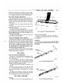
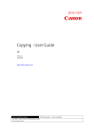
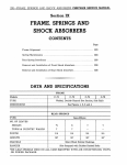
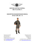
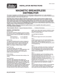
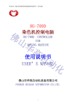
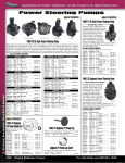
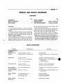
GROUP 17
SPRINGS AND SHOCK ABSORBERS
CONIINTS
Page
Page
1
1
3
SHOCK ABSORBERS . . . .
............
2
SPECIFICATIONS
(At Rear of Manual)
TIGHTENING REFERENCE . . . . (At Rear of Manual)
DESCRIPTION . . . . . . . . . . . . . . . . . . . . .
SERVICE DIAGNOSIS
REAR SPRINGS
Description
It is important that spring " U " bolts be inspected
at regular intervals and kept tight to prevent spring
breakage.
The spring shackles should be inspected occasionally to make sure they are tight, but not binding. N o
lubrication of any kind should be used on the rear
springs or rubber bushings.
Zinc Interleaves—Zinc Interleaves are used between the spring leaves for heavy duty suspension
equipped vehicles to help increase spring life. Zinc Interleaves are flat pieces of zinc or metal to help cush-
ion the spring leaves. They are used between each
leaf for heavy duty suspension.
Springs may "bottom" under abnormal loading conditions, particularly when road dips and railroad crossings are encountered at relatively high speeds.
The oriflow shock absorber cannot be refilled or
disassembled. When servicing is required, the shock
absorber must be removed and a new unit installed.
NOTE . Shock absorbers should only be replaced if
they have lost their resistance, are damaged, or if
they drip oil. Evidence of slight oil moisture on outside of shock absorber is not cause to replace them.
8
SERVICE DIAGNOSIS
Condition
Possible
Correction
Cause
S P R I N G S A N D SHOCK
ABSORBERS
SPRINGS S A G OR
(a) Springs sagged or taken set.
(a) Replace spring.
BOTTOM
(b) Broken, bent or weak spring leaves.
(b) Replace spring main leaf, or spring as necessary.
SPRING NOISE
(a) Loose " U " bolts.
(a) Tighten " U " bolt nuts 45 foot-pounds.
(b) Replace bushings and tighten shackle bolt nuts
(b) Loose or worn shackle bushings.
40 foot-pounds.
(c) Install new interliners.
(c) Worn or missing interliners.
(a) Tighten " U " bolt nuts 45 foot-pounds.
SPRING BREAKAGE
STRUT C R A C K I N G
(a) Loose " U " bolts.
(b) Replace spring and shock absorber.
(b) Shock absorber inoperative.
(a) Tighten the strut bushing bolt nut to 65 foot-
(a) Loose strut bushing bolt nut.
(b) Install new bushing. Tighten bushing bolt nut to
pounds.
OR GRUNTING N O I S E
AT REAR O F IMPERIAL
MODELS
65 foot-pounds.
(b) Faulty strut bushing.
(a) Replace bushings.
S H O C K ABSORBER
(a) Bushing excessively worn.
NOISY
(b) Faulty internal valve.
(b) Replace shock absorber.
(c) Air trapped in unit.
(c) Bleed the shock absorber.
(a) Faulty seal.
(a) Replace shock absorber.
S H O C K ABSORBER
DRIPPING OIL
17-2
SPRINGS AND SHOCK ABSORBERS
SERVICE PROCEDURES
SHOCK ABSORBERS
Front Shod Absorber Removal
(1) Remove the nut and washer (Fig. 1) from the up-
per end of the shock absorber control rod.
(2) Compress the shock absorber by pushing the
rod through the shock absorber support.
(3) Remove the lower mounting bolt and remove the
shock absorber.
(4) If the upper bushing appears worn, damaged
or deteriorated remove it by first pressing out the inner steel sleeve, then prying-out or cutting-out the
rubber bushing. (This bushing takes some permanent
set so that once removed it should be replaced.)
(5) If the lower bushing is to be replaced, remove it
from the shock absorber, using Tool C-3553 to press
on the outer sleeve of the bushing (Fig. 2). (Pressing on the inner sleeve will not remove the outer
sleeve from the shock absorber.)
Installation
(1) To aid the installation of the upper bushing, dip
the bushing in water, start it into the frame opening
with a twisting motion, then press or tap it into place.
When installed properly, the groove in the bushing
will index with the opening in the shock absorber tower.
(2) Install the steel sleeve in the bushing.
KP71
Fig. 2 — R e p l a c i n g Shock Absorber
(3) Using Tool C-3553, press the lower bushing into
the shock absorber eye until it is centered. Always
press against the outer steel sleeve to avoid damage
to the assembly.
(4) Bleed and test the shock absorber then compress
it to the shortest length.
(5) Install the lower cup washer (concave side up)
on the rod and into position.
(6) Hold the shock absorber in the installed position in the frame. Slide the upper cup washer (concave side down) over piston rod and down onto the
bushing. Install the nut finger tight.
(7) Position the lower end of the shock absorber in
the mounting bracket on the lower control arm, and
NK542
Fig. 1—Front
Shock
Absorber
Bushing
Fig. 3—Rear
Shock
Absorber
SPRINGS A N D SHOCK ABSORBERS
17-3
install the retaining bolt, lockwasher, and nut. Tighten the nut to 55 foot-pounds. While holding the piston rod, tighten the piston rod nut to 25 foot-pounds.
Rear Shock Absorber
Replacement
On Imperial models, the rear shock absorbers are
mounted on studs at the upper and lower ends. On
Chrysler models, the shock absorbers are attached to
studs on the lower ends and by bolts at the upper
ends (Fig. 3).
(1) Remove nuts and washers attaching the shock
absorbers.
(2) Inspect the bushings for wear or damage and
replace as necessary.
(3) Test and bleed the shock absorber.
(4) Position the shock absorber on the mounting
studs or bolts and install the cupped washers and nuts.
SPRING
SP-3178
N Y 204
F i g . 4—Spring
Pivot Bushing
Replacement
Do not tighten the nuts until the full weight of the
vehicle is on the wheels.
(5) Tighten the lower stud nut 50 foot-pounds and
the upper nuts 70 foot-pounds.
Testing and Bleeding
Shock
Absorbers
Hold the shock absorber in an upright position with
the dust shield or piston rod section upward. Extend
the shock absorber to the maximum length and turn
it upside down. Compress the shock absorber. Repeat
this procedure to make sure all air is removed from
sorbers are fully extended.
(2) Remove the alignment clips from the spring.
(3) Separate the spring leaves (Fig. 5) and remove
the interliners.
Installation
(1) With the leaves separated, be sure the spring
leaf area where the interliner makes contact, is clean
and smooth.
the unit. Do not extend shock absorber when it is in
the upside down or in a horizontal position, otherwise air will enter the cylinder tube.
A steady resistance should be felt when the shock
absorber is extended or compressed. If no resistance
is felt, replace the shock absorber.
REAR SPRINGS
Front Pivot Bushing
Replacement
Removal of the old bushing and installation of the
new bushing is performed in one operation using
Tool C-3709 (Fig. 4).
(1) On bolt SP-3178, position the bearing washer
SP-92, thrust bearing SP-332, bushing adapter SP-3179
(flat side of adapter next to the washer), spring leaf
bushing and remover adapter SP-3180.
(2) Insert bolt SP-3178 through the bushing to be
removed.
(3) Install adapter SP-3242 on bolt SP-3178. The
slot in adapter SP-3242 should be visible to aid in
the correct positioning of the bushing as it is being
installed.
(4) Tighten bolt SP-3178 to remove the old bushing and install the new bushing. Remove the tool after
the new bushing has been correctly positioned.
61x269B
F i g . 5 — S e p a r a t i n g Spring
Leaves
REAR SPRING INTERLINERS
;;
Removal
(1) Raise the rear of the vehicle until the shock ab-
F i g . 6 — P o s i t i o n i n g the
Interliner
61 x 2 7 0 B
17-4
SPRINGS AND SHOCK ABSORBERS
(2) Insert the interliner between the spring leaves
(Fig. 6) until the fasteners are aligned with the
holes.
(3) Force the fastener into the hole in the spring
leaf (Fig. 7).
(4) Position the aligning clip (Fig. 8) and tighten
the retainer nut. Do not lubricate the rear springs.
The interliners act as the friction control and need
no lubrication.
ZINC INTERLEAF REPLACEMENT (Heavy Duty
Suspension—AC-1, A C - 2 , A C - 3 Models)
(1) Remove the rear spring.
(2) Remove the center bolt from the spring and separate the leaves.
(3) Install the zinc interleaves between the spring
leaves and install the center bolt.
(4) Tighten the center bolt to 10 foot-pounds.
Measuring
Rear Spring
Height
When measuring the rear spring heights, the vehicle
should be placed on a level floor, have the correct
front suspension height, the correct tire pressures, no
passenger or luggage compartment load and a full
tank of fuel.
(1) Jounce the vehicle several times (front bumper
first). Release the bumpers at the same point in each
cycle.
(2) Measure the shortest distance from the highest
point on the underside of the rear axle bumper strap
(at the rear of the bumper) to the top of the axle housing.
(3) Measure both the right and left sides.
If these measurements vary by more than % inch
(from side to side), it is an indication that one of the
rear springs may need replacing. It is normal for rear
springs to show some reverse arch, even with no load,
so appearance alone should not be the reason for
spring replacement.
Rear Spring
61 x 2 7 2 B
F i g . 8—Positioning
Clip
floor stands and jack pressure under the axle housing, disconnect the shock absorbers from the studs on
the spring plates.
(2) Lower the jack until it supports only the weight
of the axle housing and remove the rear spring rear
shackle (Fig. 9).
(3) Loosen the rear spring pivot bolt nut. The nut
should be backed off until it is retained on the pivot
bolt by two or three threads.
(4) Using a pry bar between the pivot bolt nut and
the body frame, force the pivot bolt outward until the
nut contacts the spring mounting bracket.
(5) Remove the pivot bolt nut and using a suitable
tool, force the. pivot bolt out of the spring.
(6) Remove the spring " U " bolts and the spring.
Rear Spring
Installation
(1) Position the springs in their respective front
NUT
INSERT
C.._
/
BUSHING
PLATE
STATION
WAGON
Removal
Alignment
SPRING
SHACKLE
(1) With the vehicle body frame supported on the
SHACKLE
BUSHING
BUSHING
SCREW
NK536
61 x 271B
Fig. 7—Installing
Interliner
Fastener
Fig. 9 — R e a r Spring
Assembly
SPRINGS AND SHOCK ABSORBERS
hangers and install the pivot bolts and nuts (finger
tight only).
(2) Install the spring shackles and nuts.
(3) Install the spring " U " bolts and nuts.
(4) Tighten the spring U-bolt nuts 50 foot-pounds
and shackle bolt nuts 40 foot-pounds.
(5) Connect the shock absorbers.
17-5
(6) Remove the vehicle floor stands and with the
vehicle weight on the wheels, tighten the front pivot
bolt to 125 foot-pounds torque.
(7) The bushings and shackles should not be lubricated at any time. Measure the vehicle curb height
whenever a rear spring or shackle has been replaced.