1
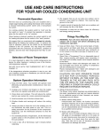
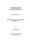
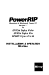
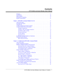
TABLE OF C O N T E N T S
Page
No
.
INTRODUCTION
.............................................................
1
...........................................................
1
............................................................
2
BASIC PROCEDURE
TEST EQUIPMENT
..................................................
2
.....................................................
2
............................................................
2
.......................................
2
......................................
2
............................
3
Vacuum-Tube Voltmeter
R-F Signal Generator
POWER SUPPLIES
General Function of the Power Supply
Localizing Trouble to the Power Supply
Isolating and Locating Trouble in the Power Supply
AUDIO CIRCUITS
............................................................
5
General Function of the Audio Circuits . . . . . . . . . . . . . . . . . . . . . . . . . . . . . . . . . . . . . . .
5
Localizing Trouble to the Audio Circuits . . . . . . . . . . . . . . . . . . . . . . . . . . . . . . . . . . . . . .
5
Isolating and Locating Trouble in the Audio Circuits
...........................
5
...............................................................
General Function of the I-F Circuits . . . . . . . . . . . . . . . . . . . . . . . . . . . . . . . . . . . . . . . . . .
8
.........................................
8
I-F CIRCUITS
Localizing Trouble to the I-F Circuits
Isolating and Locating Trouble in the I-F Circuits . . . . . . . . . . . . . . . . . . . . . . . . . . . . . . .
8
8
CONVERTER (OSCILLATOR AND MIXER) CIRCUITS . . . . . . . . . . . . . . . . . . . . . . . . . . . . . . . . . . .
9
General Function of the Converter Circuits . . . . . . . . . . . . . . . . . . . . . . . . . . . . . . . . . . . .
9
Localizing Trouble to the Converter Circuits . . . . . . . . . . . . . . . . . . . . . . . . . . . . . . . . . . . .
9
........................
10
Isolating and Locating Trouble in the Converter Circuits
......................................................
11
.................................
11
Localizing Trouble to the R-F Circuits . . . . . . . . . . . . . . . . . . . . . . . . . . . . . . . . . . . . . . . . .
11
lsolating and Locating Trouble in the R-F Circuits . . . . . . . . . . . . . . . . . . . . . . . . . . . . . . .
11
R-F AMPLIFIER CIRCUITS
General Function of the R-F Amplifier Circuits
.
.
Copyright, 1952 PHlLCO CORPORATION
C
TROUBLE-SHOOTING TECHNIQUES
INTRODUCTION
This handbook is intended to familiarize the technician with a
methodical procedure for trouble-shooting radio receivers primarily,
but the principles can also be applied to other types of electronic
equipment. This method, which is simplified and easy to use, results in faster, more efficient servicing. Personnel with limited
experience will find that it enables them to trouble-shoot equipment with a minimum of time and. labor.
BASIC PROCEDURE
In order to simplify the use of schematic diagrams,
certain test points have been specially marked with
letter symbols.
The basic method of trouble shooting has three
principal subdivisions:
1. General LOCALIZATION of trouble to a single
SECTION of the radio receiver, by making checks a t
certain designated test points.
2. ISOLATION of the faulty CIRCUIT within
chat section by making checks at other test points
designated in the procedure.
3. LOCATION of the defective PART within t h a t
circuit by making simple voltage and resistance measurements, and in some cases, part substitutions.
The functional sections into which the receiver is
divided for trouble shooting are:
1. Power supply.
2. Audio circuits.
3. I-F, detector, and a-v-ccircuits.
4. R-Fand converter circuits.
Analysis by functional sections enables the technician
to apply this knowledge to any particular radio. A
typical block diagram of a superheterodyne radio receiver is shown in figure 1.
NOTE: The trouble-shooting procedure in this manual i s
bared on the assumption that the various sections of
the radio ore checked in the order given, and that
when a defective component is found, the trouble is
cleored before proceeding.
ANTENNA
SPEAKER
AUDIO
OSCILLATOR
POWER
SUPPLY
TP2-977
Figure I .
Block D i a g r a m of Typical Superheterodyne Receiver
TROUBLE-SHOOTING TECHNIQUES
POWER SUPPLIES
TEST EQUIPMENT
For efficient radio servicing it is important that the
technician be equipped with the necessary test equip
ment. The following equipment is desirable:
VACUUM-TUBE VOLTMETER
A good vacuum-tube voltmeter, such as the Philco
Electronic Circuit Master Model 7001, is capable of
making all the measurements required in the everyday
work of the serviceman. These include:
D-C voltage ranges to 1000 volts; current ranges
to 100 m a and 30 amp.
A-C voltage ranges to 1000 volts (60 to 400 cycles);
current ranges to 10 amp.
Resistance ranges to 1000 megohms.
Capacitance ranges to 50,000 ppf and 500 pf.
GENERAL FUNCTION OF THE
POWER SUPPLY
The power supply in a radio receiver performs the
following functions:
1. Supplies the proper filament voltage to all sections.
2. Supplies the proper B-plus voltage to all sections.
3. Supplies bias voltage to some sect ions.
4. Provides adequate filtering when the source of
supply is other than pure direct current supplied by a
battery.
LOCALIZING TROUBLE TO THE
POWER SUPPLY
WARNING
If a vacuum-tube voltmeter is not available, a good
volt-ohm-milliammeter such as the Philco Circuit
Tester Model 7005, may be used for most of these measurements.
When moking msistonce measurements, or when trouble
R-F SIGNAL GENERATOR
sistor, and with the hand well insulated, short-circuit
The &plus
voltoge is high enough to cause injury.
When making voltoge measurements, be coreful not to
touch live
terminals.
shooting, turn off the power. Using o low-volue re-
When trouble-shooting r-f, i-f, and audio circuits, a
good r-f signal generator, such as Philco Model 7070,
is required. A generator of this type is capable of
radio-frequency coverage from 100 kc. to 110 mc. (six
bands), with a 400-cycle modulating frequency also
available.
the filter copociton. Failure to do this may result in
damoge to the test equipment.
1. A resistance measurement between B plus and B
minus should be made at the output of the filter network. The resistance measured will vary with each
radio, and should be in accordance with the manufac-
TP2-978
Figure 2.
A-C Power Supply
TROUBLE-SHOOTING TECHNIQUES
turer's specifications. Normally this resistance will be
approximately that of the bleeder resistor, or in circuits
that do not have a bleeder resistor, the resistance will
be approximately that of a good output filter capacitor.
If the resistance is too low, check for shorts before
turning the set on.
2. When the power is turned on, allow the tubes to
warm up for several minutes. Listen and look for arcing, crackling noises, or unusual odors emanating from
the radio. If any of these conditions exist, turn off the
radio immediately and seek out the parts causing these
noises or odors. If none of the above symptoms appear,
check the B-plus voltage at the output of the power supply. This is done to determine whether the power supply is a source'of trouble. An abnormal voitage reading
at this point (as compared to the value given in the
service manual for that model) indicates that there is
trouble within the power supply. The next step in the
trouble-shooting procedure consists of isolating the
trouble to a particular circuit in the power supply.
ISOLATING AND LOCATING TROUBLE
IN 'THE POWER SUPPLY
A-C Power Supplies
A typical a-c power supply is shown in figure 2.
With this type of power supply the a-c line voltage
is connected (through the on-off switch) to the primary of the power transformer (TI). The high voltage output of the power transformer is connected to
the plates of the rectifier tube. A pulsating d.c. at the
output (cathode) of the rectifier tube is then connected
to the filter network. Troubles localized to the power
supply can therefore be isolated by a logical sequence of
voltage and resistance checks, starting at the output
of the filter network and working back to the rectifier
tube and the power transformer.
As shown in figure 2, the filter choke ( L l ) is connected to one side of the rectifier tube filament; this
connection is usually made at the rectifier tube socket.
The other side of L1 connects to the B-plus terminal of
the power-supply output (test point B). Therefore, locating this lead in the chassis and tracing it from L1
to a terminal will locate the B-plus point in the chassis.
CAUTION
To prevent damage, always use the highest range of
the voltmeter when measuring unknown voltage values.
After the approximate value is determined, disconnect
the meter, select a suitable range, and then reconnect
the meter.
Most troubles in power supplies are caused by a
breakdown of parts in the filter circuits. Inasmuch as
the filter circuits are practically alike for all power
supplies operated on a.c., the procedure for isolating
and locating trouble described here should be followed.
T o isolate trouble in an a-c power supply, begin by
measuring the voltage from test point B to B minus
(test point A). Low voltage at this test point is usually
the result of a leaky output filter capacitor (C4), a
defective bleeder resistor ( R l ) , or a high-resistance
filter choke (Ll). If there is no voltage between test
point B and B minus (test point A) look for a shofted
filter capacitor (C4), an open filter choke (Ll) or a
defective bleeder resistor (Rl). Continuing through the
circuit, measure the voltage between test point C and
B minus (test point A). Low voltage here indicates a
leaky filter capacitor (C3) or a defective rectifier tube.
Absence of voltage at this test point is the result of a
defective rectifier tube or a shorted filter capacitor (C3).
The voltage between test point D and test point E
shodld equal the full, a-c, high-voltage output of the
power transformer (TI). Low voltage between test
points D and E could be caused by a low-resistance
(partially shorted) secondary winding or low a-c line
voltage. Zero voltage between test points D and E
indicates an open secondary winding. Check for a high
resistance or open winding between test points D or E
and B minus (test point A); approximately one half
(depending on the location of the tap), the full a-c,
rated, output voltage of the power transformer should
be indicated. If a' continuity check shows a normal
indication for all secondary windings, check for a highresistance primary, an open primary, or a shorted line
by-pass capacitor (C1 or C2).
WARNING
The voltage stored in filter capacitors deer r-f c!v:cy:
leak off when the power supply is disconnected from
the supply line. To avoid shock, short-circuit all capacitors with a low-value resistor before handling components of power supply. Avoid personal contact with
the live terminals.
A-C/D-C Power Supplies
A typical a-c/d-c power supply is shown in figure 3.
The a-c line voltage is connected directly to the radio
tubes through the on-off switch, S1. The tube filaments, connected in series, drop the line voltage proportionally, and all tubes have the same filament-current rating. The B-voltage circuit uses one side of the
a-c line as B minus (test point A). The cathode of the
rectifier tube is connected directly to the input of the
filter network. This filter differs from the a-c filter circuit only in the use of resistors (R1 and R2) in place
of the choke.
TROUBLE-SHOOTING TECHNIQUES
RECTIFIER
II
Figure 3.
A-C/D-C Power S u p p l y
Comparable, relative voltages are shown in figure 3.
These voltages by no means constitute actual voltages
of the radio under test. For exact voltage measurements,
refer to the service information provided by the manuf acturer.
T o isolate trouble in this type of power supply, start
by measuring the voltage from test point B to B minus
(test point A). Low voltage at this test point is usually
an indication of a leaky filter capacitor (C4) or a defective filter resistor (R2). Absence of voltage at test point
B is caused by a short circuit in filter capacitor C4 or
an open circuit in filter resistor R2.
Having eliminated the possible troubles at test point
B, proceed with voltage checks from test point C to B
minus (test point A). Low voltage at this test point is
usually caused by leaky filter capacitors (C3 or C4) or
defective filter resistor (Rl). If there is no voltage at
test point' C, filter capacitor C3 is short-circuited or
filter resistor R l is open.
Low voltage between test point D and B minus (test
point A) can be caused by a defective rectifier tube,
leaky or open filter capacitor (C2), shorted filter capacitor (C3 or C4), or a shorted pilot lamp (11). A
no-voltage condition will be present when the rectifier
tube is defective or filter capacitor C2 is shorted.
A defective switch (Sl), line cord, or line-cord plug
(Wl), or a shorted line-filter capacitor (Cl) should not
be overlooked as possible sources of trouble.
Vibrator Power Supplies
Vibrator power supplies contain the following major components: vibrator (VBI), power transformer
( T I ) , rectifier, and filter networks, as shown in figure 4.
The common troubles found in vibrator power supplies
RF CHOKE
Figure 4.
Vibrator Power S u p p l y
nnnr
are complete inoperation, noise, erratic operation, and
low voltage output.
Complete inoperation is usually caused by an open
or short circuit, o r a defective vibrator (VB1). Measuring the input voltage at the fuse terminals of the
power supply will disclose an open supply line or a
blown fuse. If the vibrator is operating normally, a
slight buzz can usually be heard, or by gently touching
the vibrator case, a slight vibration can be felt. If the
vibrator is inoperative, check the components of the
input filter circuits for open circuits. If the vibrator
is operating, measure the a-c voltage across the secondary of the power transformer ( T I ) , using a high scale
of the a-c voltmeter. Zero, or low voltage reading at
this point indicates a possible short circuit, or partial
short circuit in buffer capacitor C3. T h e remainder of
the vibrator power supply is similar to a-c power
supplies.
Noise is usually caused by loose connections or loose
shielding. A n interference known as vibrator hash,
caused by arcing of the vibrator contacts, will be quite
objectionable unless all shielding contact surfaces are
tight and clean, and the shielding is well grounded.
Often this type of interference can be corrected by replacing the vibrator (VB1) with a new one.
Erratic operation is caused by a high-resistance or
loose connections, or a defective vibrator. A systematic
check of all components is necessary to locate the
trouble. Often resoldering all connections to the input
filter circuit will correct erratic operation. In some
instances, replacing the vibrator will correct the
trouble.
Low output voltage is usually caused by a partially
shorted filter capacitor, a weak rectifier tube, or defective vibrator. Resistance measurements will reveal
faulty filter capacitors. T h e vibrator (VB1) can be
tested i n a power supply known to be operating
properly.
Battery Power Supplies
Many radio sets use dry batteries for power. Noisy,
weak, o r erratic operation of the radio is usually caused
by batteries which have weakened beyond their useful life.
AUDIO ClRCLllTS
GENERAL FUNCTION OF THE
AUDIO CIRCUITS
T h e second audio amplifier, or output amplifier, is
designed to amplify the signal voltage from the first
audio amplifier and to convert this voltage to audio
power sufficient to drive the speaker.
T h e first audio amplifier tube operates as a voltage
amplifier. I t amplifies the output signal voltage from
the detector to a level sufficient to drive the output
audio amplifier.
TROUBLE-SHOOTINGTECHNIQUES
IS1 AUDIO
ourput
TP2-981
Figure 5.
Typical Audio Amplifier
LOCALIZING TROUBLE TO THE
AUDIO CIRCUITS
NOTE: The checks in this section are based on the
assumption that the power supply i s functioning normally.
I n order to determine whether the audio circuits are
at fault, an audio signal generator and a vacuum-tube
voltmeter or 20,000 ohms-per-volt voltmeter are required.
Most of the audio circuits to which the signal is
supplied by the signal have high-impedance input circuits; therefore when it is desired to make tests without
causing undue disturbance to these high-impedance
,
.
clrcults, coacect s small c p c i t o r ir: series with the
output lead of the signal generator. Usually capacitance
between 100 ppf. and 0.001 pf. will be found satisfactory.
T h e diagram in figure 5 shows the audio circuits of
a typical radio receiver. T h e test points are indicated
by the letters A, B, and C.
T o determine whether the audio circuits are at fault,
inject a moderate signal at the grid of the first audio
tube (test point B). T h e normal indication at the
speaker should be a loud, clear signal. If a normal
indication is not obtained, the trouble may be assumed
to be i n the audio circuits.
ISOLATING A N D LOCATING TROUBLE
IN THE AUDIO CIRCUITS
T h e trouble has now been LOCALIZED to the audio
section of the receiver; the next step to be considered
is the ISOLATION of the faulty circujt within that
section.
TROUBLE-SHOOTING TECHNIQUES
Using an audio signal generator, inject a signal at
the control grid of the audio output tube (test point C,
figure 5). With a strong signal input the normal indication at the speaker should be a loud, clear signal. If
this is not the case, the audio output circuit may be
assumed to be at fault. If the normal indication is present, the stage may be assumed to be operating correctly, and the trouble is in the first audio amplifier
circuit.
Once the faulty circuit has been ISOLATED, the
next step is to LOCATE the defective part within that
circuit.
Troubles That Occur in Audio
Output Circuits
NOTE: Before proceeding with circuit test, certain p r c
liminary checks should be made. Carefully inspect both
the top and bottom of the chassis. Make sure that a l l
tubes ore secure in the proper sockets, and look for
broken or shorted connections, burned resistors, or other
obvious sources of trouble.
T h e cathode by-pass capacitor (C4) can be a source
of trouble, because of internal short circuits, open
circuits, or leakage. An inherent characteristic of electrolytic capacitors, is that they tend to dry out with
age, and as a result the capacitance decreases sharply.
T h e effect on the circuit is similar to having an open
capacitor.
An open cathode by-pass capacitor (C4) will cause
low gain and poor frequency response. This condition
can be detected by shorting the capacitor with one of
similar value or larger. Immediate improvement in
output proves that the original capacitor is open.
If the by-pass capacitor is paralleled as before, but
no improvement in output results, the capacitor may
have a bad leak or a short circuit. Because of the decrease in bias due to the short-circuited capacitor, the
plate current increases and causes an abnormal voltage
drop across the primary of the output transformer. The
plate voltage is lowered, and the potential difference
between the plate and screen is large. These symptoms
can be regarded as further indications of the trouble
in the by-pass capacitor. It is always wise to check the
cathode resistor before replacing the capacitor, as an
open resistor may have caused the breakdown of the
capacitor.
T h e capacitor should be replaced with one of similar
value. It is important that polarity be observed when
installing electrolytic capacitors.
The cathode biasing resistor (R4) carries heavy current, and is consequently subject to heating which may
cause it to change in value or open-circuit.
If the resistor changes in value the tone quality will
be affected.
An open cathode resistor renders the output stage
practically inqperative so far as normal signal amplification is concerned. However, if a strong signal is
fed into the grid circuit of this stage, some signal output will be obtained. The signal will not be constant
and definitely will be distorted. It will sound choked.
D-C voltage measurements will indicate that the
plate voltage, the screen voltage, and the cathode voltage are higher than normal with respect to B minus.
Resistance measurements will be normal from plate
to B minus and from screen to B minus, but the resistance of the cathode will be equal to the leakage
resistance of the cathode capacitor. Since this leakage
resistance is many times greater than the normal value
of the cathode resistor, this check is a positive means
of verifying the failure of the cathode resistor.
Hum or badly distorted signals at the speaker may
be caused by an open grid resistor (R3). An open circuit here removes the bias, from the tube, and causes
the plate to draw heavy current. The result is an abnormal voltage drop across the primary winding of the
output transformer, and consequently a lower voltage
at the plate. The screen voltage remains practically unaffected; therefore the difference of potential between
the screen and plate will be large, affording another clue to this type of trouble.
A 20-percent margin of error is allowed when replacing this resistor, although the ideal replacement
would be one of like value.
Breakdowns in the tone compensating capacitor
(C5) sometimes occur, because of the high, a-c, signal
voltages to which it is subjected, and the high d-c
potential established if one side of this capacitor is
grounded. Because of the high voltages the dielectric
breaks down, and the capacitor is short-circuited. Because of its position in the receiver circuit, the defective capacitor short-circuits the output transformer
( T I ) , and the result is a dead set. An open tone compensation capacitor is difficult to detect. because of the
fact that the only appreciable effect is an increased
h i ~ h ~ f r e q u e n cresponse.
y . ..
When replacing this capacitor, use one of exactly
the same value and breakdown rating, as any change
in its value will directly affect the frequency response
of the receiver.
T h e most common trouble associated with the output transformer (Tl) is that of an open primary. This
winding is subjected to the same high d-c voltage and
a-c signal voltage as are applied to the tone compensation capacitor. If the plate circuit opens, the screen
grid, which is operating at a positive potential, will
attract the full cathode emission. This element is not
designed to carry this heavy current and consequently
will glow bright red. This symptom.can be used as a
guide in determining that the plate circuit is open.
When replacing the output transformer select one
of exactly the same rating. If this is not available a
universal type may be substituted.
One of the causes of trouble in the audio output
w'
stage that is most overlooked is that of a defective
speaker (LS1). An open voice coil will result in a dead
speaker. Therefore it is wise to test the speaker by
continuity check or by substitution. If the speaker produces an erratic buzz, look for iron filings or other
foreign particles lodged in the air gap.
When replacing the speaker, select one of like rating in order to obtain a proper impedance match.
A common source of trouble in the audio output
stage is the tube itself. T h e trouble may result from
low emission, which directly affects the gain and power
handling capacity of the tube. Loose or shorted elements may cause the tube to be noisy. T h e most effective means of checking this trouble is by tube substitution.
Troubles That Occur in
Audio-Amplifier Circuits
If plate load resistor (R2) is open, B plus potential
is removed from the plate of the audio tube, stopping
current flow through the entire plate circuit. Carbon
(composition) resistors are generally used in highresistance, low-current circuits of this type. Aging, and
overheating by excessive currents may cause them to
open. Since the resistor is removed from the plate,
trouble symptoms are: extremely high resistance between plate and ground, normal resistance between
cathode and ground, and extremely high resistance
between plate and B plus.
A short-circuited plate load resistor can be detected
in several ways. The short-circuit eliminates the voltage
drop across the resistor, and this can be observed on the
voltmeter. The increased potential on the plate causes
greater current flow through the circuit, and hence
increased IR drop across the cathode resistor. This too
can be detected by the voltmeter. Since the plate resistor is short-circuited, the resistance between plate
and ground is about eyual to r h e hlppd~rresistance of
the power supply; between cathode and ground it is
normal; and between plate and B plus it is zero.
Carbon resistors themselves do not usually shortcircuit, although certain types sometimes drop in resistance value.
A short-circuit between the audio tube plate and
ground places the plate of the tube at ground potential, causing tube current to stop flowing. Since it is
connected to B plus, there is a large IR drop across
the plate load resistor, due to the greatly increased
current through it. A voltage check will confirm this
fault. Since the plate is shorted to ground, the resistance between plate and ground is zero; between
cathode and ground it is normal.
This trouble is usually caused by a short-circuited
r-f by-pass capacitor (C2, figure 5 ) , a small mica capacitor shunted across the output circuit of the first
audio tube to by-pass to ground any stray r-f or i-t cur-
TROUBLE-SHOOTING TECHNIQUES
rents not completely removed from the audio signal
by preceding filters.
When cathode biasing is employed, it should be
noted that a short-circuited by-pass capacitor between
plate and cathode would produce somewhat different
effects from those occurring when the plate is grounded. In this case heavy current would pass through the
cathode resistor, producing a large voltage drop across
this part. This method of by-passing is not illustrated
in the circuit of figure 5, but as this plate-to-cathode
connection is often used for by-pass capacitors instead
of the plate-to-ground connection, the distinction in
the effects produced should be thoroughly understood.
Sometimes the plate is grounded by accidental contact of the plate lead of the by-pass capacitor with the
chassis or some grounded object.
Since every trouble mentioned in this description
results in no output from the first audio tube, there is
no signal from the loud speaker.
T h e input coupling capacitor ( C l ) is not a frequent
cause of trouble. However, it may open, rendering the
circuit inoperative by removing the signal to the grid
of the first audio tube.
This capacitor can be easily tested by injecting an
audio signal at the grid of the first audio tube; if the
normal indication is present at the loudspeaker, the circuit is operating correctly. If the normal indication is
not present when the signal is next injected at the
volume control the input coupler can be assumed to be
defective.
When replacing, use a capacitor of like value and
rating. Place it in the same position as the defective
component and use care in dressing the leads. Lead
dress in this location is important, because any hum
picked up as a result of misplaced leads will be amplified through the entire amplifier circuit.
The output coupling capacitor (C3) is frequently a
cause of trouble. If it opens the result is a dead receiver because the signal is no longer coupled from
the first a-f tube to the grid of the second a-f tube.
If it becomes short-circuited, tone quality will be
seriously affected. This is due to the fact that positive
voltage from the first a-f plate is connected through the
defective component to the grid of the output tube,
causing variations in grid voltage which produce distortion.
An open grid load resistor ( R l ) removes the bias
from the first a-f tube and causes motorboating or hum.
This condition is similar to that which was described
for the grid load resistor in the audio output stage.
When replacing this resistor choose one of exactly
the same resistance, because any change in value of this
part will have a direct effect on grid bias, and will
probably result in poor tone.
The first a-f tube is often a source of trouble. Such
effects as hum, intermittent operation, noise, poor
TROUBLE-SHOOTING TECHNIQUES
reception, or dead receiver may be caused by it. Some
of the causes of trouble may not even be detected by a
tube checker; the only practical way to check this tube
is to replace it with one known to be good. If the
trouble persists, it can be assumed that the original
tube was not at fault.
I-F CIRCUITS
point C, figure 6); use a reliable signal generator tuned
to the intermediate frequency of the receiver. If a clear
modulated note is heard at the loud speaker, the i-f
section is in normal working order. An abnormal
indication at this point indicates trouble within the i-f
circuits, which can be isolated in the following paragraphs.
ISOLATING AND LOCATING TROUBLE
IN THE I-F CIRCUITS
GENERAL FUNCTION OF THE
I-F CIRCUITS
The intermediate frequency (i-f) section or stage of
the radio performs the following functions:
1. Amplifies the modulated difference frequency resulting from the mixing of the local-oscillator output
with the incoming radio frequency (r.f.).
2. Couples the combined, audio-modulated, i-f signal to the detector, where the i-f portion is filtered out,
allowing only the detected audio component to pass
through to the first audio amplifier.
3. Provides additional selectivity.
LOCALIZING TROUBLE TO THE
I-F CIRCUITS
A typical i-f circuit is shown in figure 6; the three
major parts with their associated components are the
input i-f transformer ( Z l ) , the i-f amplifier tube, and
the output i-f transformer (22).
Troubles That Occur in
I-F Circuits
The function of the output i-f transformer is to
couple the output signal from the i-f amplifier tube to
the second detector. If a modulated signal at the intermediate frequency is applied to the grid of the i-f
amplifier tube (between test points A and B) a clear
modulated note should be heard at the loudspeaker.
If the signal does not pass through, check the foIlowing
component parts of the output i-f section:
1. Check the i-f amplifier tube; a similar tube of
known quality may be substituted.
NOTE: The checks in this section are based on the assumption that the power supply and the audio circuits
are functioning normally.
T o either localize or eliminate the i-f section as a
source of trouble, inject a modulated signal at the plate
of the converter tube (between test point A and test
2. Check for a misaligned output i-f transformer by
injecting the i-f test signal at the grid (test point B)
of the i-f amplifier tube. With the aid of an output
meter connected from the plate of the second audio-
I
1
AVC
I
C3
T
'P'
-
TP2-982
Figure 6.
Typical I-F Amplifier
TROUBLE-SHOOTING TECHNIQUES
frequency amplifier tube to B minus, adjust TC4 and
TC3 (located on 22) for maximum output. When aligning a section or stage, the r-f circuits leading back to
the antenna should be made inoperative. This is best
done by grounding the oscillator stator of the tuning
gang. If aligning the stage does not cure the trouble,
check for a defective i-f transformer (22).
3. Check for a defective circuit component associated with the output tube and output i-f transformer
( 2 2 ) , such as a defective cathode resistor (R2), or a
shorted cathode capacitor (Cl). Lack of B-plus voltage
at the plate and screen of the i-f amplifier tube can be
traced to a short-circuited B-plus by-pass condenser
(C2). Abnormal voltage at the screen of the i-f amplifier tube can be traced to a defective screen dropping
resistor (Rl). If there is B-plus voltage at the screen,
but not at the plate, of the i-f amplifier tube, check
for an open primary coil (TC3) in the output i-f transformer (22). The i-f filter resistor (R3) and the volume
control (R4) are actually part of a voltage divider.
An increase in resistance of R3 will proportionally decrease the output voltage to the detector. If the filter
resistor (R3) is open, there will be no voltage
- output
to the grid of the-first audio amplifier.
Troubles That Occur in Detector
and A-V-C Circuits
The detector circuit consists essentially of a tuned
circuit, a voltage divider, and a half-wave rectifier.
The tuned circuit is the output section of 22, and is
tuned to the intermediate frequency, usually 455 kc.
In series with the tuned circuit is the voltage divider;
this includes the i-f filter resistor (R3) and the detector
load resistor, which is also the volume control (R4).
The low side of the latter is at B minus, as is the cathode
of the half-wave rectifier tube. Conduction through the
tube from the cathode (pin 4) to the diode plate (pin 1;)
completes the circuit.
Trouble in this circuit can be isolated and lccated by
substitution of the detector tube, resistance measurements of R3 and R4, and a continuity check between
terminals 1 and 2 of 2 2 . A resistance check between
terminals 2 and 5, and terminals 5 and 6 of 2 2 will
determine whether an i-f filter capacitor is shortcircuited.
The a-v-c voltage is developed across resistors R3 and
R4 and is present at the other diode plate (pin 5) of
the combined detector-avc tube. The a-v-c voltage is
negative, and is fed to the r-f stages. The i.f. is filtered
out to B minus through the a-v-c filter capacitor (C3).
If C3 becomes shorted, a-v-c voltage disappears, but if
the capacitor is open-circuited spurious signals will
appear in the audio output because of the i-f component
feeding back to the r-f stages. If the a-v-c filter resistor
(R5) is open no a-v-c voltage will be developed, because the voltage divider is no longer complete.
The input i-f transformer is also tuned to the intermediate frequency of the particular receiver. The function of the input i-f transformer is to couple the signal
from the converter plate to the grid of the i-f amplifier
tube. Having eliminated all possible sources of trouble
in the i-f amplifier tube and the output i-f transformer,
the only remaining check to make is a continuity check
of the input i-f transformer.
CONVERTER (OSCILLATOR AND
MIXER) CIRCUITS
GENERAL FUNCTION OF
CONVERTER CIRCUITS
The function of the converter is to supply an unmodulated r-f. signal of a fixed amplitude and of a
frequency different from (and usually higher than) the
incoming broadcast signal by exactly the amount of
the intermediate frequency. I t also beats the r-f input
signal against the signal of the oscillator stage to produce the intermediate-frequency signal.
LOCALIZING TROUBLE TO THE
CONVERTER CIRCUITS
NOTE: The checks in this section are based on the
assumption that the power supply, audio, i-f, detector,
and a-v-c circuits are functioning normally.
The circuit diagram of a typical converter is shown
in figure 7. The test points are indicated by the letters
A, B, and C.
/
TRANS
1
8
+
8
+
+Ti
AVC
.1Ur
- -.
Figure 7.
Typical Converter
TP2~583
9
TROUBLE-SHOOTING TECHNIQUES
T o determine whether the oscillator section of the
converter is at fault set the receiver on 700kc., and
using a signal generator, inject a modulated signal of
slightly less than 700kc. at the mixer grid (test point
B). As the signal-generator frequency is advanced a
note is heard in the loudspeaker at the frequency of
the modulating signal and gradually disappears again
as the generator frequency passes 700kc. If by the
above procedure the oscillator section is shown to be
operating, the mixer section is at fault.
ISOLATING AND LOCATING
TROUBLE IN CONVERTER CIRCUITS
Troubles That Occur in
Oscillator Circuits
Trouble localized to an r-f oscillator stage is frequently found to be one of three types: failure to
oscillate, weak oscillation, or oscillation at the wrong
frequency.
If the tube fails to oscillate, there will be no output
from the receiver. The trouble usually can be traced
to an open or short-circuited coupling between the
plate and grid circuit of the tube, an open or shortcircuited grid resistor (R2), a short-circuited trimmer
or tuning capacitor, or a faulty tube. Some tubes will
be encountered which test satisfactorily on a tube
tester; yet, when placed in the circuit, fail to oscillate.
T h e first step in isolating trouble in an oscillator stage
is to check the socket voltages against the voltages
indicated on the schematic for the specific receiver
under test. Any material deviation from the given
standards indicates trouble in that portion of the circuit
where incorrect voltage occurs. Localization of the
faulty component can be accomplished quickly by continuity and resistance checks with .ao nh.mrneter Svhstitution of a new tube is advisable when voltage and
resistance checks fail to disclose any part failures.
Weak oscillation produces a considerable loss of
sensitivity in a receiver, with an attendant drop in
over-all performance. The fault generally lies in an
open or partially shorted coupling between the grid
and plate circuits of the tube. Where the coupling is
capacitive, a leaky capacitor will decrease the arnplitude of oscillation. In the case of transformer coupling,
a partially short-circuited or open coupling coil will
have a similar effect. Check coupling capacitors for
leaks, and coils for continuity. Low plate voltage will
cause weak oscillation. I n converter tubes, low screen
voltage or lack of screen voltage produces a like
result.
Oscillation at the wrong frequency is characterized
by either no response from a receiver or reception of
only a portion of the coverage of the receiver at either
the lower or upper end of the band, depending upon
which side of the fundamental frequency the oscillator
is designed to operate. This condition can be caused by
a change in the value of components, a partially shorted
tank coil or tuning capacitor, an incorrectly aligned
oscillator, or a faulty tube. Trouble from a faulty tube
is most evident at the higher frequencies, where a
change in the interelectrode capacitance of the tube
elements can cause a frequency shift. Check components
for value, and test for continuity and short-circuits.
Troubles That Occur in
Mixer Circuits
When troubles are isolated to a mixer stage, the
various frequencies and tube-socket voltages encountered must be considered. The function of a mixer stage
is to beat the r-f input signal against the signal of the
oscillator stage to produce the intermediate-frequency
signaL T o obtain this result, the tube voltages are critical; therefore the first step in isolating trouble within
a mixer stage is a comparison of voltage measurements
with those specified on the schematic diagram for the
particular receiver.
-
-
T h e common troubles in a mixer stage are complete
inoperation, weakness, distortion, intermittent operation, and noise.
In an inoperative stage, voltage measurements at
the tube socket, followed by resistance measurements of
the circuits in question, will usually disclose any open
or shorted components. T h e components to be concerned with are: shorted R2, shorted C5, open C2, or
a defective converter tube.
A weak mixer stage may be caused by the changing
in value or partial breakdown of any of the components mentioned above. Voltage and resistance measurements will usually disclose the defective part.
Distortion can be caused by a faulty tube or improper bias voltages. T h e tube should be changed if
there is any doubt, regardless of its condition as indicated by a tube tester. Defective components in the
cathode and control-grid circuits cause improper bias
voltage, and each capacitor and rksistor should be
individually checked to determine its condition. The
typical circuit diagram (figure 7) should be closely
followed to avoid overlooking a component in the
interconnecting grid, cathode, and plate circuits.
Intermittent trouble in a mixer stage is often difficult
to locate because many components and circuit conditions can cause this trouble. Service and operation
reports should be studied, then the receiver should be
placed in operation for a reasonable length of time to
TROUBLE-SHOOTING TECHNIQUES
allow the trouble to appear before any circuits are disturbed. Should the radio operate correctly during this
period, all wiring and components should be moved
and tapped gently with an insulated prod. If the receiver cuts in and out rapidly, there is generally a loose
connection in the wiring. Should this action be slow,
there may be a dielectric leakage, or a circuit may be
opening and closing by thermal action. Voltage measurements made when the receiver is operating will not
indicate the trouble. The application of test instruments to an intermittent circuit may create a very small
voltage fluctuation that would cause the circuit to
resume operation. Therefore a very careful visual
examination of electrical components, soldered and
mechanical connections is important.
eliminates image frequencies common to radio receivers of the superheterodyne variety.
LOCALIZING TROUBLE TO THE
R-F CIRCUITS
NOTE: The checks in this section are based on the
assumption that all other circuits are operating normally.
Using an r-f modulated signal generator, inject a
signal at the antenna input (test point B, figure 8).
The normal indication at the speaker, with a weak
signal input, should be a loud clear signal. If the indication is abnormal the r-f amplifier may be assumed
to be at fault.
ISOLATING AND LOCATING
TROUBLE I N R-F AMPLIFIER CIRCUITS
Noise which has been isolated to a mixer stage may
be due to low signal gain in the r-f stages. Should a
low-gain r-f signal be impressed on the mixer stage,
the noise frequencies may be amplified more than the
signal. This condition should be determined, as it cannot be corrected in the mixer stage.
A typical r-f amplifier is shown in figure 8, and the
test points are indicated by the letters A, B, C, and D.
Troubles That Occur in R-F
Amplifier Circuits
The common troubles in r-f amplifiers are: complete inoperation, intermittent operation, weakness,
oscillation, and distortion.
R-F AMPLIFIER
GENERAL FUNCTION OF THE
R-F AMPLIFIER
A stage is usually inoperative because of lack of
voltage at one or more points, or because of a shorted
or open circuit. The circuit components to check, and
their defects are: open C1, open or shorted loop, shorted
R3, open 21, shorted C6, open C3, open or shorted
The r-f amplifier is designed to increase the sensitivity and selectivity of the receiver. It also contributes
to noise reduction by providing a stronger input signal
for the converter circuit. It improves a-v-c action and
LIT
ANT
/
-
I N T E N M I SECTION O F
TUNING GANG
PAP1
TP2-984
Figure 8.
TypicalR-F Amplifier
TROUBLE-SHOOTING TECHNIQUES
TC1 or TC2, shorted C2, open R2, or a defective antenna section of the tuning gang. The usual voltage
and resistance measurements should indicate the defective component quickly.
A n intermittent r-f stage should receive the same
treatment as intermittent mixer stages.
Low amplification in an r-f stage is generally caused
by improper voltage, partially open or shorted coil
windings in 2 1 o r 22, or misalignment.
A stage operating at low gain will give partial voltage and resistance readings, and extreme care should
be taken to apply them logically to the apparent
trouble.
Oscillation may be due to loose shielding, a defective
tube, or interstage coupling. T o check these conditions,
place the receiver in operation and tap coil 2 1 and the
tube with the hand. Examine all shielded wiring for
cuts, worn spots, and poor ground connections. Vacuum
tubes can cause oscillation by virtue of leakage between
elements, and since tube testers do not always indicate
this condition, the tube should be replaced if no part
failure has been found.
Distortion is usually caused by improper bias voltage, which may be traced to a defective R1, R2, C5, or
other components which may be in the biasing circuits. Potentials should be measured at the tube socket,
and should be followed by resistance measurements if
there are any discrepancies. Close examination of all
soldered connections and mounting hardware is
necessary.