1
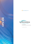
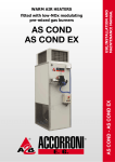
Publication T3-722
Dated: April 15, 2006
Service Manual
T30-M
TURBOTWIN Air Motor
TDI TURBOTWINÔ
FROM
TECH DEVELOPMENT
TABLE OF CONTENTS
Section
1.0
2.0
3.0
4.0
5.0
6.0
Subject
Introduction………………………………………..
Description of Basic Groups……………………..
Disassembly……………………………………….
Cleaning and Inspection………………………….
Assembly…………………………………………..
Parts…………………………………………………
Page
1
3
5
7
10
12
LIST OF TABLES
Table No.
1
2
3
4
5
6
Title
Page
T30 Series Service Tool Kits…………………….. 5
Cleaning Materials and Compounds………….… 7
Parts Inspection Check Requirements………….. 8
Parts Wear Limits……………………………….…. 9
Torque Values……………………………………… 9
Materials for Assembly……………………………..10
LIST OF ILLUSTRATIONS
Figure
1
2
3
4
5
6
7
8
9
10
Title
Page
TDI Turbotwin Nameplate………………………… 2
T30 Series Part Number Coding………………… 2
Turbine Housing Assembly………………………. 3
Gearbox Housing Assembly……………………... 4
Carrier Shaft Disassembly…….……………….… 5
Turbine Rotor Removal…………………………… 6
Nozzle 2 Removal………………………………… 6
Turbine Shaft Removal…………………………… 6
Turbine Shaft Installation………………………….10
T30-M Illustrated Parts Breakdown………………14
Page: i
Publication T3-722
Issued April 15, 2006
TDI TURBOTWIN™
FROM TECH
SECTION 1.0 INTRODUCTION
1.1 GENERAL INFORMATION
This manual provides information for servicing,
disassembly, and re-assembly of the TDI Turbotwin
T30-M air motor. If there are questions not answered
by this manual, please contact your local TDI
distributor or dealer for assistance. Illustrations and
exploded views are provided to aid in disassembly and
re-assembly.
The TDI Turbotwin T30-M air motor fits a wide range of
engine applications up to 20 horsepower. One basic
design can be used on a broad range of pre-lube and
post-lube pump motors, plus extended cycle
operations.
The Turbotwin T30-M air motor is suited to operate
within a wide range of inlet pressures and ambient
temperatures. This motor is designed for operation
with either compressed air or natural gas.
The robust turbine motor design in the Turbotwin T30M air motor has no rubbing parts, and is therefore
tolerant of hard and liquid contamination in the supply
gas with almost no adverse affects. The motor is well
adapted to running on “sour” natural gas.
As with all TDI air motor products, there are no rubbing
parts so there is no lubrication required.
This
eliminates failures due to lubricator problems, the
expense of installing and maintaining the system, and
the messy and hazardous oil film around the motor
exhaust. The motor is factory grease packed for the
life of the motor so it requires no maintenance.
NOTE
Throughout this manual, the term “air” is used to
donate the motor drive medium. Unless otherwise
stated, “air” means compressed air or natural gas.
Please review the rest of this manual before attempting
to provide service to the TDI Turbotwin T30-M air
motor.
DEVELOPMENT
WARNING - used where injury to personnel or
damage to equipment is likely.
CAUTION - used where there is the possibility
of damage to equipment.
NOTE - use to point out special interest
information.
1.3 DESCRIPTION OF OPERATION
The Turbotwin T30-M air motor is powered by a pair of
axial flow turbines coupled to a simple planetary gear
reduction set.
The high horsepower of the turbine air motor combined
with the planetary gear speed reducer results in a very
efficient and compact unit. The Turbotwin T30-M air
motor can be used over a wide range of drive
pressures from 30 psig (2 BAR) to 120 psig (8 BAR)
and is suitable for operation on either air or natural gas.
The T30-M weighs approximately 29 pounds (13KG)
and is capable of delivering over 25 HP (18.7 kW) of
cranking power at the maximum pressure of 120 psig
(8 BAR).
1.4 INSTALLATION AND SERVICE
It is important to properly install and operate the T30-M
air motor to receive the full benefits of the turbine drive
advantages. It must be installed in accordance with the
instructions provided by Tech Development, Inc. (TDI).
WARNING
Failure to properly install the motor or failure to operate
it according to instructions provided byTDI may result in
damage to the motor or cause personal injury. DO
NOT OPERATE THIS MOTOR UNLESS IT IS
PROPERLY INSTALLED.
Repair technicians or service organizations without
turbine motor experience should not attempt to repair
this motor until they receive factory approved training
from TDI, or its representatives. Proper operation and
repair of your TDI Turbotwin will assure continuous
reliability and superior performance for many years.
1.2 WARNINGS, CAUTIONS, & NOTES
Throughout this manual, certain types of information
will be highlighted for your attention:
Publication T3-722
Issued April 15, 2006
Page 1
TDI TURBOTWIN™
FROM TECH
TURBOTWIN™
1.5 NAMEPLATE INFORMATION
The nameplate, located on the turbine housing,
provides
important
information
regarding
the
construction of your T30-M air motor, refer to Figure 1.
The part number coding explanation, refer to Figure 2,
can help you when talking to your distributor.
DEVELOPMENT
PNUEMATIC MOTOR
SERIAL NO.
T30-M
CW (RH)
TECH DEVELOPMENT INC.
6800 POE AVE.,DAYTON
OH
MODEL NO.
(CCW)LH)
9708-105
X.
PART NUMBER
NOTE
You should always have the motor’s Part Number,
Serial Number, Operating Pressure, and Direction of
Rotation information before calling your TDI distributor
or dealer.
T306-60016-00L-1
.
AIR OR NAT. GAS USAGE HOUSING PROOF PRESSURE IS 600 PSIG
MAX OPERATING INLET PRESS. 120
WARNING
PSIG
DO NOT OPERATE UNLOADED, WITHOUT EXHAST
GUARD OR WITHOUT EXHAUST FITTING
Figure 1. TDI TURBOTWIN Nameplate
Figure 2. T30 Series Part Number Coding
Page 2
Publication T3-722
Issued April 15, 2006
TDI TURBOTWIN™
FROM TECH
SECTION 2.0 DESCRIPTION OF
BASIC GROUPS
2.1 GENERAL
The TDI Turbotwin T30-M air motor is a lightweight,
compact unit driven by a two stage turbine air motor.
The motor is composed of two basic assembly groups:
Turbine Housing Assembly and Gearbox Housing
Assembly.
DEVELOPMENT
2.2 TURBINE HOUSING ASSEMBLY
The Turbine housing assembly, refer to figure 3,
consists of a stage one (18) and a stage two turbine
rotor (9) mounted on sungear shaft (24). The front
bearing (8) is secured by a retainer plate (22) and the
aft bearing is pre-load by a spring washer (12).
The ring gear (25) is installed into the front of the
turbine housing (21) and secured by four screws.
Figure 3. Turbine Housing Assembly
Publication T3-722
Issued April 15, 2006
Page 3
TDI TURBOTWIN™
FROM TECH
2.3 GEARBOX HOUSING ASSEMBLY
The gearbox housing assembly, refer to figure 4,
consist of a planet gear carrier and output shaft (26),
three planet gears (29), needle bearings (30), spacers
(28), and planet shafts (27).
DEVELOPMENT
The carrier shaft (26) is mounted on two ball bearings
(31, 37) in the gearbox housing (35). The retainer nut
(38) secures the carrier shaft and the front bearing (37)
in the gearbox housing. The aft bearing (31) is
preloaded by use of a spring washer (32).
Figure 4. Gearbox Housing Assembly
Page 4
Publication T3-722
Issued April 15, 2006
TDI TURBOTWIN™
FROM TECH
DEVELOPMENT
SECTION 3.0 DISASSEMBLY
3.1 GENERAL
Always mark adjacent parts on the motor housing;
Nozzle 2/ Containment Ring (13), Turbine Housing
(19), Gearbox Housing (35) so these parts can be
located in the same relative position when the motor is
re-assembled.
Do not disassemble the motor any further than
necessary to replace a worn or damaged part, unless a
complete overhaul is being performed.
Always have a complete set of seals and o-rings on
hand before starting any overall of a Turbotwin T30-M
air motor. Never use old seals or o-rings.
The tools listed in Table 1 are suggested for use by
technicians servicing the Turbotwin T30-M air motor.
The best results can be expected when these tools are
used, however, the use of other tools are acceptable.
brace may be required. Remove spacer (34) and
spring washer (32) from carrier shaft.
Press bearing (37) from gearbox housing (35) by
tapping inner race.
3.3.3 Carrier Shaft/Planet Gear Disassembly
Place carrier shaft/gear assembly on arbor press with
shaft up. With carrier shaft (26) supported, press each
planet shaft (27) out opposite the spline shaft. Refer to
figure 5.
Remove the planet gears (29) and spacers (28) from
the carrier shaft (26).
Needle bearings (30)
replacement is required.
may
be
pressed
out
if
TOOL DESCRIPTION
TDI/PN
Spanner wrench
2-27272
Stage 2 Rotor Puller Tool
52-20076
Tool, Turbine Bearing
45-25294
Tool, Bearing/Seal
2-26943
Table 1. T30 Service Tool Kit (P/N: T30-27639)
3.2 GEARBOX HOUSING
3.3.1 Removal of Gearbox Housing
Remove the four screws (42) and remove the flange
(41) from the gearbox assembly (35)
Remove four screws (36) and separate the gearbox
assembly from the turbine assembly.
Figure 5. Carrier Shaft Disassembly
3.4 TURBINE HOUSING
3.3.2 Gearbox Disassembly
3.4.1 Stage 2 Rotor Removal
Set the gearbox on the gearbox holding tool with the
three holes on the gearbox over the dowel pins on the
holding tool.
Remove seven screws (3), and remove the exhaust
elbow (5) from the turbine assembly (16)
Install spanner wrench on the bearing retaining nut (38)
and turn CCW to remove.
Hold the stage 2 rotor (9) and remove the turbine screw
(7) and washer (8).
Apply pressure to the carrier shaft (26) to remove it
from the gearbox housing (35). An arbor press and
Install rotor puller tool P/N 52-20076 and remove the
stage 2 rotor per figure 6.
Publication T3-722
Issued April 15, 2006
Page 5
TDI TURBOTWIN™
FROM TECH
Remove the square key (10)) from turbine shaft (24).
DEVELOPMENT
Remove the bearing spacer (13) from the turbine shaft.
Remove turbine bearing (11) and preload spring (12)
from nozzle 2 (16).
Remove four screws (23) and bearing retainer plate
(22) from turbine housing (21).
Press turbine shaft (24) through turbine housing (21) as
shown in figure 8. Remove bearing spacer from
turbine shaft.
Remove the stage 1 rotor (18) and square key (10).
Press turbine shaft. (24) through bearing (11) to
remove bearing from shaft.
Figure 6. Turbine Rotor Removal
Press the lip seal (19) from the turbine housing by
applying pressure to the seal through the housing.
3.4.2 Turbine Housing Disassembly
Remove five screws (17) from the stage 2 nozzle (16)
and separate it from turbine housing (21). If turbine
housing is too tight, it can be removed by installing two
threaded screws into nozzle 2 (exhaust end) and using
them as jacks to separate the turbine housing from
nozzle 2. The stage 1 rotor may require slight rotation
to allow the threaded screws to travel through the holes
in the rotor. Refer to Figure 7.
Figure 8. Turbine Shaft Removal
Figure 7. Nozzle 2 Removal
Page 6
Publication T3-722
Issued April 15, 2006
TDI TURBOTWIN™
FROM TECH
DEVELOPMENT
SECTION 4.0 CLEANING and
INSPECTION
Clean aluminum parts using the solutions per Table 2;
soak for 5 minutes. Remove parts, rinse in hot water,
and dry thoroughly.
4.1 CLEANING
Clean corroded steel parts with a commercially
approved stripper.
Degrease all metal parts, except bearings, using a
commercially approved solvent. Refer to Table 2.
NOTE
Never wash bendix assembly or bearings in cleaning
solvents. It is recommended that the bearings be
replaced with new parts.
Clean corroded aluminum parts by cleaning as stated
above and then immerse the parts in chromic-nitricphosphoric acid pickle solution per Table 2. Rinse in
hot water and dry thoroughly.
MATERIAL or COMPOUND
Degreasing Solvent (Trichloroethylene) (O-T-634)
Acetone
Aluminum Cleaning Solution
MANUFACTURER
Commercially Available
Commercially Available
Diversey Corp., 212 W. Monroe, Chicago, IL 60606
Dissolve 5 oz of Diversey 808 per gallon of water at
155°- 165°F.
Steel Cleaner - Rust & Corrosion
Oakite Products Corp., 50 Valley Rd., Berkeley
Heights, NJ 07992
Mix 3-5 lb. of Oakite rust Stripper per gallon of water;
use at 160°- 180°F.
Chromic-Nitric-Phosphoric Acid Pickle Solution
Mix 8lb. of chromic acid, 1.9 gal. of phosphoric acid,
1.5 gal. of nitric acid with enough water to make a
total of 10 gal. of solution.
WARNING Follow all instructions provided with the MSDS sheets on the materials and compounds listed
above.
Table 2. Cleaning Materials and Compounds
4.2 INSPECTION
Use Table 3 as a guide to check for acceptable
condition of the parts listed.
Check all threaded parts for galled, crossed stripped, or
broken threads.
Check all parts for cracks, corrosion, distortion, scoring,
or general damage.
Publication T3-722
Issued April 15, 2006
Check all bearing bores for wear and scoring. Bearing
bores shall be free of scoring lines, not to exceed
0.005″ width and 0.005″ depth.
Check gear teeth and turbine housing ring gear for
wear. In general, visually check for spalling, fretting,
surface flaking, chipping, splitting, and corrosion. If
wear is apparent, check the gear teeth dimensions in
accordance with Table 4. Nicks and dents that cannot
be felt with a .020 inch radius scribe are acceptable.
Page 7
TDI TURBOTWIN™
FROM TECH
Part
Description
Planet Gear
Check For
Cracked, chipped, or galled
teeth. Wear must not exceed
limits per Table 4.
Carrier Shaft
Cracks, scoring or raised
metal in planet shaft holes
and keyways.
Integrity of
knurl connection.
Planet Pins
Wear grooves or flat spots
Washers
Gearbox Housing
Sungear/Turbine
Shaft
Wear created grooves
Cracks and Breakage
Cracks, scoring, wear created
grooves, chipped or broken
gear- teeth, galling or scoring
on bearing surface of shaft.
Raised metal on the keyway.
Parallelism of end surfaces
Cracks and breakage
Spacers
Turbine Housing
Ring Gear
Seal Assembly
Seal Spacer
Needle Bearings
Ball bearings
Containment
Ring/ Nozzle
Turbine Rotors
Cracks, wear, chipped, or
broken gear teeth.
Wear grooves or scratched
surfaces on carbon ring.
Wear Grooves
Freedom of needle rollers
Freedom of rotation without
excessive play between races
Corrosion, erosion, cracks
and broken nozzle edges.
Corrosion, erosion,
and broken edges.
cracks
DEVELOPMENT
Requirements
(Defective Parts Must Be Replaced)
Wear must not exceed limits per table 4.
There shall be no evidence of excessive
wear.
Deformation of metal smearing in planet
pin holes & keyways not acceptable.
Scoring on bearing diameter not to
exceed .005″ depth.
Wear must not exceed limits per Table 4.
Wear grooves in flat spots not permitted.
Wear must not exceed limits per Table 4.
Wear must not exceed limits per Table 4.
Cracks and breakage not acceptable.
Wear must not exceed limits per Table 4.
Ends must be parallel within 0.0005″.
Cracks and breakage are not acceptable.
Minor surface damage is permitted if
function is not impaired.
Wear must not exceed limits per Table 4.
Wear is not permitted.
No wear permitted.
Replace bearings
Replace bearings
Cracks and breakage are not acceptable.
Minor surface damage is permitted if
function is not impaired.
Minor tip rub is permitted if function is not
impaired.
Tip wear; bore and key way Wear is not permitted.
wear
Table 3. Parts Inspection Check Requirements
Page 8
Publication T3-722
Issued April 15, 2006
TDI TURBOTWIN™
FROM TECH
PART DESCRIPTION
LIMIT, Inches
Ring gear / Turbine Housing
Internal
measurement
between two .084″ diameter 5.0890 max.
pins.
Sun Gear / Turbine Shaft
0.6690 min
Bearing diameter
External measurement over
two .096 diameter pins.
7.5:1
0.952 min
9:1
0.808 min
11.4:1
0.670 min
Planet Gear
External measurement over
two .0864″ diameter pins.
2.3067 min
7.5:1
2.3699 min
9:1
2.4359 min
11.4:1
Carrier Shaft
1.1800 min
Bearing Diameter
0.8750 max
Planet Pin Bore
Planet Pins
0.873 min
Bearing Diameter
Thrust Washer
.055 min
Thickness
Table 4. Parts Wear Limits
Publication T3-722
Issued April 15, 2006
DEVELOPMENT
TORQUE
In-lbs
Nm
1 (Screw)
50
68
4 (Screw)
180
245
14 (Screw)
75
102
21 (Screw)
113
154
33 (Screw)
113
154
38 (Retainer Nut)
125
170
* Refer to section 6 for part number identification.
Table 5. Torque Values
ITEM NUMBER *
Page 9
TDI TURBOTWIN™
FROM TECH
DEVELOPMENT
SECTION 5.0 ASSEMBLY
5.1 GENERAL INFORMATION
The tools listed in Table 1 are suggested for use by
technicians servicing the Turbotwin T30-M air motor.
The best results can be expected when these tools are
used, however, the use of other tools is acceptable.
CAUTION
Replace all screws, o-rings, lip seals, and bearings
when the T30-M motor is assembled. These parts are
included in the overhaul kit shown in the Parts List,
Section 6.0.
NOTE
Always press the inner race of a ball bearing when
installing a bearing onto a shaft. Always press the
outer race of a ball bearing when installing into a
housing.
Lubricate all o-rings with petroleum jelly or Parker Oring Lube before assembly unless otherwise noted.
Refer to Table 6 for a list of materials to be used during
assembly.
Figure 9. Turbine Shaft Installation
Install the bearing retainer (22) onto the turbine
housing (21) and secure with four screws (23) Torque
to 113 in-lbs.
5.2.2
MATERIALS
SOURCE
Petroleum Jelly
Commercially Available
Parker-O-Ring Lube
Commercially Available
Loctite RC290
Commercially Available
Grease, gearbox
TDI P/N 9-94121-001
Table 6. Materials for Assembly
5.2 TURBINE HOUSING
5.2.1
TURBINE BEARING INSTALLATION
Press the lip seal (19) onto the large end of he bearing
spacer (20) with the lips facing up.
Press the lip seal/bearing spacer assembly (19,20) into
the stage 1 turbine housing (21).
Press the turbine bearing (11) onto the turbine shaft
(24) until seated using press tool 2-26943.
Press the turbine bearing/shaft assembly (11,24) into
the turbine housing (21). Use press tool P/N 2-26943 if
required per figure 9. Do not press on the end of the
shaft because the load could damage the balls of the
bearings.
Page 10
722
ROTOR 1 INSTALLATION
Turn the turbine nozzle over (exhaust end up) and
press the square key (10) into the turbine shaft (24)
until seated.
Install stage 1 rotor (18) by sliding over turbine shaft
(24), while simultaneously aligning the key with the
keyway in the rotor.
5.2.3
STAGE 2 NOZLE INSTALLATION
Slip o-ring (6) over stage 1 rotor and into the groove of
the turbine housing (21).
Install the stage 2 nozzle (16) over the turbine housing
(21) and secure with five (17) hex screws. Torque to 75
in-lb.
NOTE
The air inlet port on nozzle 2 must be aligned with the
casting indentation on the turbine housing.
Publication T3Issued April 15, 2006
TDI TURBOTWIN™
FROM TECH
5.2.4
ROTOR 2 INSTALLATION
Slide bearing spacer (13) over turbine shaft (24). Place
pre-load spring (12) into bearing bore.
Apply a light coating of oil to the bearing bore in the
nozzle 2 containment assembly and press the bearing
over the turbine shaft and into the bearing bore.
Insert key (10) into turbine shaft keyway and install
stage 2 rotor (9) onto shaft, while simultaneously
aligning the key with the keyway in the rotor.
Secure stage 2 rotor with rotor washer (5) and rotor
screw (4). Torque to 180 in-lb.
If removed Install plug (14) into nozzle 2 containment
assembly.
Hand press ring (25) gear into turbine housing with ring
gear holes aligning with holes on gearbox.
5.3 GEAR BOX ASSEMBLY
5.3.1 PLANETARY GEAR CARRIER ASSEMBLY
If disassembled, press needle bearings (30) into planet
gear (29) using arbor press.
Place thrust washer (28) on each side of planet gear
(29) and install into carrier shaft (26) slot opening.
Press planet shafts (27) into the carrier weldment using
arbor press.
5.3.2
DEVELOPMENT
Place wavy washer (32) and bearing spacer on carrier
shaft. The wavy washer should be centered on rear
bearing.
Place carrier shaft assembly on a flat surface and hand
press the gearbox housing (35) onto carrier shaft.
Press forward bearing (37) over carrier shaft and into
gearbox housing using arbor press.
Place carrier shaft assembly on holding tool. Install
locknut (38) onto carrier shaft. Tighten locknut using
spanner wrench. Torque to 125 in-lb.
5.4 FINAL ASSEMBLY
Temporarily install one screw (36) into ring gear (25) to
prevent it from rotating while applying grease. Remove
screw after grease is applied to ring gear.
Apply liberal amounts of grease (approximately 100115 grams) to planet gears (29), turbine shaft sun gear
(24), and ring gear (25).
CAUTION
The grease used in the planetary system has a shelf
life of 2 years. Therefore, if the starter is NOT installed
and operated on the engine for 2 years after the starter
is manufactured, the grease should be replaced prior to
starter operation. The manufactured date is reflected
in the starter serial number. (Ex: 0602-0567 has a
manufactured date of February 2006).
Align gearbox assembly with turbine assembly and
secure with four screws.
CARRIER SHAFT INSTALLATION
Press lip seal (33) into aft side on gearbox housing (35)
with lips facing up.
Press lip seal (39) into mounting flange (41) with lips
facing forward.
Install o-ring (40) on mounting flange (41)
Press aft bearing (31) onto carrier shaft using arbor
press.
Install flange (41) on gearbox assembly using four
screws (42).
Install exhaust elbow (5) using seven screws (3).
Torque to 50 in-lb.
Publication T3-722
Issued April 15, 2006
Page 11
TDI TURBOTWIN™
FROM TECH
SECTION 6.0 PARTS LIST
The components illustrated and/or described in this
section are for the Turbotwin T30-M air motor.
ITEM #
DESCRIPTION
1
Inlet Adaptor, 2" NPT; S/N: Before 9608-001
2
Screw Used with Item #1 Before 9608-001
3
Screw
4
Hollow Hex Plug, Exhaust Check Port
5
Exhaust Adaptor Elbow (Before S/N: 9608-001)
5
Exhaust Elbow, 11/2" NPT (After S/N: 9608-001)
6
O-Ring
7
Screw, Rotor Attachment
8
Rotor Washer
9
Stage 2 Rotor
10
Square Key (1/8")
11
Turbine Bearing
12
Bearing Pre-Load Spring
13
Bearing Spacer
14
Hollow Hex Plug
15
1" NPT Caplug
16
Stage 2 Noz/ Containment (RH)
16
Stage 2 Noz/ Containment (LH)
17
Screw
18
Stage 1 Rotor
19
Lip Seal
20
Spacer/SealBearing
21
Turbine Hsg. / Stage 1 (3 Noz. RH)
21
Turbine Hsg. / Stage 1 (3 Noz. LH)
21
Turbine Hsg. / Stage 1 (6 Noz. RH)
21
Turbine Hsg. / Stage 1 (6 Noz. LH)
21
Turbine Hsg. / Stage 1 (12 Noz. RH)
21
Turbine Hsg. / Stage 1 (12 Noz. LH)
22
Bearing Retainer
23
Screw
24
Turbine Shaft (11.4:1)
25
Ring Gear
26
Carrier Shaft Weldment (11.4:1)
27
Planet Shaft
28
Planet Gear Spacer
29
Planet Gear (11.4:1)
Page 12
722
DEVELOPMENT
When rebuilding the T30-M, it is recommended to
purchase and completely install the appropriate service
kit(s).
PART NUMBER
2-27275
14F-31218-028
14F-16432-008
9-93501-002
2-27248
2-27555
9-90001-047
14F-25028-012
9-93047
2-27232
9-90220-050
9-91224
9-90439
9-93091-003
9-93501-002
9-93502-006
2-27405-00R
2-27405-00L
24F-25020-012
2-27225
2-26719
9-93114
2-27389-03R
2-27389-03L
2-27389-06R
2-27389-06L
2-27389-12R
2-27389-12L
2-27406
14F-25020-012
2-27391-002
2-27395
2-27422-001
2-22051
9-93065
2-21988
QTY
1
4
7
1
1
1
2
1
1
1
2
2
1
1
1
1
1
1
5
1
2
1
1
1
1
1
1
1
1
4
1
1
1
3
6
3
Overhaul Kit
T30M-27625001
√
√
√
√
√
√
√
√
√
√
Publication T3Issued April 15, 2006
TDI TURBOTWIN™
FROM TECH
ITEM #
DESCRIPTION
30 Planet Bearing
31 Gearbox Bearing
32 Bearing Pre-Load Spring
33 Lip Seal, Gearbox Grease
34 Bearing Spacer (Gearbox)
35 Gearbox Housing
36 Hex Bolts (Gearbox Attachment)
37 Gearbox Bearing (Sames as #31)
38 Bearing Retainer Nut
39 Lip Seal
40 O-Ring
41 Mounting Flange
42 Screw
43 Inlet O-Ring used only before S/N: 9608-001
44 O-Ring (Gearbox to Turbine Assy)
Publication T3-722
Issued April 15, 2006
PART NUMBER
9-91389
9-91394
9-90402-023
9-90033
9-93119
2-27408
14F-25020-024
9-91394
9-92105-006
2-23978
9-90001-039
2-23976
14F-25020-012
9-90001-035
9-90001-049
QTY
3
1
1
1
1
1
4
1
1
1
1
1
4
1
1
DEVELOPMENT
Overhaul Kit
T30M-27625-001
√
√
√
√
√
√
√
√
√
√
√
Page 13
TDI TURBOTWIN™
FROM TECH
DEVELOPMENT
Figure 10. T30-M Illustrated Parts Breakdown
Page 14
722
Publication T3Issued April 15, 2006