1
Model AT-C1
Machine Code: B230/B237
SERVICE MANUAL
Apr. 21st, 2006
Subject to change
B230 Service Manual
21-Apr-2006
Read This First
Safety Notices
Important Safety Notices
Prevention of Physical Injury
1.
Before disassembling or assembling parts of the copier and peripherals, make sure that
the copier power cord is unplugged.
2.
The wall outlet should be near the copier and easily accessible.
3.
If any adjustment or operation check has to be made with exterior covers off or open
while the main switch is turned on, keep hands away from electrified or mechanically
driven components.
4.
The copier drives some of its components when it completes the warm-up period. Be
careful to keep hands away from the mechanical and electrical components as the copier
starts operation.
5.
The inside and the metal parts of the fusing unit become extremely hot while the copier is
operating. Be careful to avoid touching those components with your bare hands.
Health Safety Conditions
1.
Toner and developer are non-toxic, but if you get either of them in your eyes by accident,
it may cause temporary eye discomfort. Immediately wash eyes with plenty of water. If
unsuccessful, get medical attention.
2.
The copier, which use high voltage power source, can generate ozone gas. High ozone
density is harmful to human health. Therefore, the machine must be installed in a
well-ventilated room.
Observance of Electrical Safety Standards
The copier and its peripherals must be serviced by a customer service representative who
has completed the training course on those models.
Keep the machine away from flammable liquids, gases, and aerosols. A fire or an
explosion might occur.
The Controller board on this machine contains a lithium battery. The danger of
i
B230 Service Manual
21-Apr-2006
explosion exists if a battery of this type is incorrectly replaced. Replace only with the
same or an equivalent type recommended by the manufacturer. Discard batteries in
accordance with the manufacturer's instructions and local regulations.
The optional fax and memory expansion units contain lithium batteries, which can
explode if replaced incorrectly. Replace only with the same or an equivalent type
recommended by the manufacturer. Do not recharge or burn the batteries. Used
batteries must be handled in accordance with local regulations.
Safety and Ecological Notes for Disposal
1.
Do not incinerate toner bottles or used toner. Toner dust may ignite suddenly when
exposed to an open flame.
2.
Dispose of used toner, the maintenance unit which includes developer or the organic
photoconductor in accordance with local regulations. (These are non-toxic supplies.)
3.
Dispose of replaced parts in accordance with local regulations.
4.
When keeping used lithium batteries in order to dispose of them later, do not put more
than 100 batteries per sealed box. Storing larger numbers or not sealing them apart may
lead to chemical reactions and heat build-up.
Laser Safety
The Center for Devices and Radiological Health (CDRH) prohibits the repair of laser-based
optical units in the field. The optical housing unit can only be repaired in a factory or at a
location with the requisite equipment. The laser subsystem is replaceable in the field by a
qualified Customer Engineer. The laser chassis is not repairable in the field. Customer
engineers are therefore directed to return all chassis and laser subsystems to the factory or
service depot when replacement of the optical subsystem is required.
Use of controls, or adjustment, or performance of procedures other than
those specified in this manual may result in hazardous radiation exposure.
WARNING: Turn off the main switch before attempting any of the procedures in the
Laser Optics Housing Unit section. Laser beams can seriously damage your eyes.
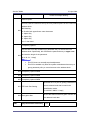
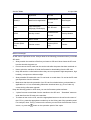
CAUTION MARKING:
ii
B230 Service Manual
21-Apr-2006
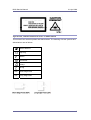
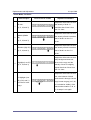
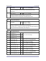
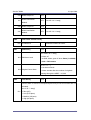
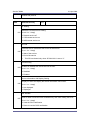
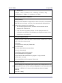
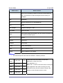
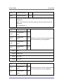
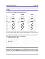
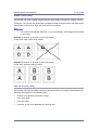
Symbols, Abbreviations and Trademarks
This manual uses several symbols and abbreviations. The meaning of those symbols and
abbreviations are as follows:
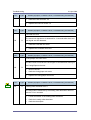
See or Refer to
Clip ring
Screw
Connector
Clamp
E-ring
SEF
Short Edge Feed
LEF
Long Edge Feed
iii
B230 Service Manual
21-Apr-2006
Trademarks
Microsoft®, Windows®, and MS-DOS® are registered trademarks of Microsoft Corporation in
the United States and /or other countries.
PostScript® is a registered trademark of Adobe Systems, Incorporated.
PCL® is a registered trademark of Hewlett-Packard Company.
Ethernet® is a registered trademark of Xerox Corporation.
PowerPC® is a registered trademark of International Business Machines Corporation.
Other product names used herein are for identification purposes only and may be trademarks
of their respective companies. We disclaim any and all rights involved with those marks.
iv
B230 Service Manual
21-Apr-2006
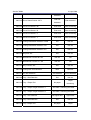
Table of Contents
Read This First ...................................................................................................................... i
Safety Notices .................................................................................................................... i
Important Safety Notices ................................................................................................ i
Safety and Ecological Notes for Disposal ...................................................................... ii
Laser Safety .................................................................................................................. ii
Symbols, Abbreviations and Trademarks ..........................................................................iii
Trademarks................................................................................................................... iv
Table of Contents.................................................................................................................. v
1.
Installation ..................................................................................................................... 1
Installation Requirements.................................................................................................. 1
Environment ..................................................................................................................1
Machine Level ............................................................................................................... 1
Machine Space Requirements....................................................................................... 2
Power Requirements ..................................................................................................... 2
Optional Unit Combinations...............................................................................................3
Machine Options............................................................................................................ 3
Controller Options.......................................................................................................... 3
Copier Installation ............................................................................................................. 5
Power Sockets for Peripherals ...................................................................................... 5
Installation Flow Chart ...................................................................................................6
Accessory Check........................................................................................................... 7
Installation Procedure .................................................................................................... 9
Moving the Machine .................................................................................................... 15
Transporting the Machine ............................................................................................ 16
Paper Feed Unit (B800) .................................................................................................. 17
Accessory Check......................................................................................................... 17
Installation Procedure .................................................................................................. 18
LCT (B801)...................................................................................................................... 21
Accessory Check......................................................................................................... 21
Installation Procedure .................................................................................................. 22
Auto Reverse Document Feeder (B789) ......................................................................... 25
Component Check ....................................................................................................... 25
Installation Procedure .................................................................................................. 26
1-Bin Tray Unit (B790)..................................................................................................... 29
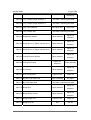
v
B230 Service Manual
21-Apr-2006
Component Check ....................................................................................................... 29
Installation Procedure .................................................................................................. 29
Shift Tray Unit (B791) ...................................................................................................... 32
Component Check ....................................................................................................... 32
Installation Procedure .................................................................................................. 33
Bridge Unit (B227)........................................................................................................... 35
Component Check ....................................................................................................... 35
Installation Procedure .................................................................................................. 35
500-Sheet Finisher (B792) .............................................................................................. 38
Accessory Check......................................................................................................... 38
Installation Procedure .................................................................................................. 39
1000-Sheet Finisher (B408) ............................................................................................ 42
Accessory Check......................................................................................................... 42
Installation Procedure .................................................................................................. 43
1000-Sheet Booklet Finisher (B793) ............................................................................... 45
Accessory Check......................................................................................................... 45
Installation Procedure .................................................................................................. 46
Punch Unit....................................................................................................................... 49
Component Check ....................................................................................................... 49
Installation ................................................................................................................... 50
Mechanical Counter (NA Only)........................................................................................ 55
Installation Procedure .................................................................................................. 55
Key Counter Bracket ....................................................................................................... 56
Installation Procedure .................................................................................................. 56
Key Counter Interface Unit .............................................................................................. 58
Installation Procedure .................................................................................................. 58
Anti-Condensation Heater (Scanner) .............................................................................. 59
Installation Procedure .................................................................................................. 59
Tray Heater ..................................................................................................................... 60
Installation Procedure .................................................................................................. 60
Controller Options ........................................................................................................... 61
Overview...................................................................................................................... 61
SD Card Appli Move .................................................................................................... 62
PostScript 3 ................................................................................................................. 65
File Format Converter.................................................................................................. 66
IEEE1394 (FireWire) ................................................................................................... 67
vi
B230 Service Manual
21-Apr-2006
IEEE1284 .................................................................................................................... 69
IEEE 802.11b (Wireless LAN)...................................................................................... 70
Bluetooth .....................................................................................................................73
Copy Data Security Unit .............................................................................................. 74
Data Overwrite Security Unit Type D (B735) ............................................................... 75
USB Host Interface ...................................................................................................... 79
PictBridge .................................................................................................................... 80
Browser Unit Type B .................................................................................................... 81
Check All Connections................................................................................................. 82
2.
Preventive Maintenance .............................................................................................. 83
Settings ........................................................................................................................... 83
Before removing the old PM parts ............................................................................... 83
After installing the new PM parts ................................................................................. 84
Preparation before operation check............................................................................. 84
Operation check .......................................................................................................... 84
Maintenance Tables ........................................................................................................ 85
Preventive Maintenance Tables ................................................................................... 85
Others in Mainframe .................................................................................................... 90
3.
Replacement and Adjustment...................................................................................... 91
Beforehand...................................................................................................................... 91
Special Tools ................................................................................................................... 92
Image Adjustment ........................................................................................................... 93
Scanning...................................................................................................................... 93
ARDF........................................................................................................................... 94
Registration ................................................................................................................. 95
Erase Margin Adjustment............................................................................................. 97
Color Registration........................................................................................................ 97
Printer Gamma Correction........................................................................................... 98
Exterior Covers ............................................................................................................. 104
Front Door ................................................................................................................. 104
Left Cover .................................................................................................................. 105
Rear Cover ................................................................................................................ 105
Right Rear Cover ....................................................................................................... 106
Operation Panel......................................................................................................... 106
Dust Filter .................................................................................................................. 107
Scanner Unit ................................................................................................................. 108
vii
B230 Service Manual
21-Apr-2006
Exposure Glass ......................................................................................................... 108
Original Length/Width Sensors .................................................................................. 109
Exposure Lamp ......................................................................................................... 109
Scanner Motor ........................................................................................................... 112
Sensor Board Unit (SBU)........................................................................................... 112
Exposure Lamp Stabilizer .......................................................................................... 113
Front Scanner Wire ................................................................................................... 114
Rear Scanner Wire .................................................................................................... 117
Touch Panel Position Adjustment .............................................................................. 118
Laser Optics .................................................................................................................. 119
Caution Decal Location.............................................................................................. 119
Laser Optics Housing Unit ......................................................................................... 119
Polygon Mirror Motor ................................................................................................. 125
Image Creation.............................................................................................................. 126
PCU ........................................................................................................................... 126
Drum Unit and Development Unit .............................................................................. 126
Toner Collection Bottle............................................................................................... 130
Toner Supply Tube Fan.............................................................................................. 131
Toner Pump Unit........................................................................................................ 131
Toner End Sensor...................................................................................................... 137
Image Transfer .............................................................................................................. 138
Image Transfer Belt Unit ............................................................................................ 138
Image Transfer Belt Cleaning Unit............................................................................. 139
Image Transfer Belt ................................................................................................... 140
Paper Transfer .............................................................................................................. 145
Paper Transfer Roller Unit ......................................................................................... 145
Paper Transfer Unit ................................................................................................... 145
ID Sensor Board ........................................................................................................ 148
Drive Unit ...................................................................................................................... 150
Drive Unit Fan............................................................................................................ 151
Gear Unit ................................................................................................................... 151
Registration Motor ..................................................................................................... 154
Paper Feed Motor...................................................................................................... 154
Drum/Development Motor-K ...................................................................................... 155
ITB Drive Motor ......................................................................................................... 156
Fusing/Paper Exit Motor ............................................................................................ 156
viii
B230 Service Manual
21-Apr-2006
Image Transfer Belt Contact Motor ............................................................................ 157
Paper Transfer Contact Motor ................................................................................... 157
Duplex Inverter Motor ................................................................................................ 158
Toner Transport Motor ............................................................................................... 158
Toner Collection Unit ................................................................................................. 159
Paper Feed Clutches ................................................................................................. 159
Drum Motor-MCY ...................................................................................................... 161
Development Motor-MCY .......................................................................................... 161
Development Clutch-K............................................................................................... 162
Fusing ........................................................................................................................... 163
Fusing Unit ................................................................................................................ 163
Fusing Belt, Pressure Roller, Fusing Lamps.............................................................. 164
Heating, Fusing and Tension Roller ........................................................................... 169
Lubricant Roller and Cleaning Roller ......................................................................... 170
Fusing/Paper Exit Fan ............................................................................................... 171
Heating Roller Thermostats ....................................................................................... 172
Heating Roller Thermistor.......................................................................................... 172
Pressure Roller Thermistor and Thermostat .............................................................. 173
Thermopile................................................................................................................. 174
Fusing Gear and One-way Clutch ............................................................................. 176
Heating Roller Bearing and Insulating Bushing ......................................................... 177
Pressure Roller Bearing............................................................................................. 179
Paper Feed ................................................................................................................... 180
Paper Feed Unit ........................................................................................................ 180
Pick-Up, Feed and Separation Rollers....................................................................... 181
Tray Lift Motor............................................................................................................ 182
Vertical Transport Sensor, Paper Overflow Sensor and Paper End Sensor .............. 183
Registration Sensor ................................................................................................... 184
By-pass Paper Size Detection Switch........................................................................ 185
By-pass Paper Feed Unit........................................................................................... 187
Duplex Unit.................................................................................................................... 188
Duplex Unit ................................................................................................................ 188
Duplex Transport Motor ............................................................................................. 188
Electrical Components .................................................................................................. 190
Controller Unit............................................................................................................ 190
Controller Box Cover ................................................................................................. 190
ix
B230 Service Manual
21-Apr-2006
Controller Box............................................................................................................ 191
BICU .......................................................................................................................... 193
IOB ............................................................................................................................ 194
PSU ........................................................................................................................... 194
SIO (Scanner In/Out) Board ...................................................................................... 195
High Voltage Supply Board........................................................................................ 196
High Voltage Supply Board Bracket........................................................................... 197
Controller Board ........................................................................................................ 198
HDD........................................................................................................................... 199
NVRAM Replacement Procedure .............................................................................. 200
4.
Troubleshooting ......................................................................................................... 203
Process Control Error Conditions.................................................................................. 203
Developer Initialization Result ................................................................................... 203
Process Control Self-Check Result ........................................................................... 204
Line Position Adjustment Result ................................................................................ 208
Scanner Test Mode ....................................................................................................... 209
VPU Test Mode.......................................................................................................... 209
BICU (IPU) Test Mode ............................................................................................... 209
Service Call Conditions ................................................................................................. 211
Summary ................................................................................................................... 211
SC Table........................................................................................................................ 215
Troubleshooting Guide .................................................................................................. 285
Image Quality ............................................................................................................ 285
Line Position Adjustment ........................................................................................... 288
Jam Detection ............................................................................................................... 295
Paper Jam Display .................................................................................................... 295
Jam Codes and Display Codes ................................................................................. 295
Electrical Component Defects ....................................................................................... 305
Sensors ..................................................................................................................... 305
Blown Fuse Conditions .............................................................................................. 310
5.
Service Tables ........................................................................................................... 311
Service Program Mode ................................................................................................. 311
Enabling and Disabling Service Program Mode ........................................................ 311
Types of SP Modes.................................................................................................... 311
Remarks .................................................................................................................... 315
Copy Service Mode....................................................................................................... 317
x
B230 Service Manual
21-Apr-2006
Service Mode Table ................................................................................................... 317
Input Check Table ...................................................................................................... 676
Output Check Table ................................................................................................... 689
Test Pattern Printing .................................................................................................. 701
Printer Service Mode..................................................................................................... 704
SP1-XXX (Service Mode) .......................................................................................... 704
Scanner Service Mode .................................................................................................. 708
SP1-XXX (System and Others) ................................................................................. 708
SP2-XXX (Scanning-image quality) ........................................................................... 708
Reboot/System Setting Reset ....................................................................................... 710
Software Reset .......................................................................................................... 710
System Settings And Copy Setting Reset.................................................................. 710
Firmware Update........................................................................................................... 712
Type of Firmware ....................................................................................................... 712
Before You Begin....................................................................................................... 713
Updating Firmware .................................................................................................... 714
Updating the LCDC for the Operation Panel.............................................................. 716
Downloading Stamp Data .......................................................................................... 717
NVRAM Data Upload/Download ................................................................................ 717
Address Book Upload/Download ............................................................................... 719
Installing Another Language ...................................................................................... 720
Handling Firmware Update Errors ............................................................................. 722
SD Card Appli Move...................................................................................................... 725
Overview.................................................................................................................... 725
Move Exec................................................................................................................. 726
Undo Exec ................................................................................................................. 726
Controller Self-Diagnostics............................................................................................ 728
Overview.................................................................................................................... 728
Detailed self-diagnostics............................................................................................ 729
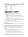
Using the Debug Log .................................................................................................... 730
Switching ON and Setting UP Save Debug Log ........................................................ 730
Retrieving the Debug Log from the HDD ................................................................... 734
Recording Errors Manually ........................................................................................ 734
New Debug Log Codes.............................................................................................. 735
Dip Switches ................................................................................................................. 737
Controller Board ........................................................................................................ 737
xi
B230 Service Manual
21-Apr-2006
BICU Board ............................................................................................................... 737
6.
Detailed Section Descriptions.................................................................................... 738
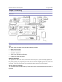
Overview ....................................................................................................................... 738
Component Layout .................................................................................................... 738
Paper Path................................................................................................................. 739
Drive Layout .............................................................................................................. 740
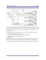
Board Structure.......................................................................................................... 741
Printing Process ........................................................................................................ 743
Process Control............................................................................................................. 745
Overview.................................................................................................................... 745
Potential Control ........................................................................................................ 745
Process Control Self Check Procedure ..................................................................... 747
Toner Density Adjustment Mode ................................................................................ 749
Toner Supply Control ................................................................................................. 749
Toner Near End/Toner End Detection ........................................................................ 751
Developer Initialization............................................................................................... 752
Scanning ....................................................................................................................... 753
Overview.................................................................................................................... 753
Scanner Drive............................................................................................................ 754
Original Size Detection .............................................................................................. 755
Anti-Condensation Heater ......................................................................................... 756
Image Processing ......................................................................................................... 757
Overview.................................................................................................................... 757
SBU (Sensor Board Unit)........................................................................................... 757
IPU (Image Processing Unit) ..................................................................................... 758
Laser Exposure ............................................................................................................. 759
Overview.................................................................................................................... 759
Optical Path ............................................................................................................... 760
Laser Synchronizing Detectors.................................................................................. 761
LD Safety Switch ....................................................................................................... 762
Automatic Line Position Adjustment .......................................................................... 763
Shutter Mechanism.................................................................................................... 767
PCU (Photo Conductor Unit) ......................................................................................... 768
Overview.................................................................................................................... 768
Around the Drum ....................................................................................................... 769
Development ............................................................................................................. 772
xii
B230 Service Manual
21-Apr-2006
Toner Supply ................................................................................................................. 775
Overview.................................................................................................................... 775
Toner Supply Mechanism .......................................................................................... 776
Toner Cartridge.......................................................................................................... 778
Waste Toner Collection ................................................................................................. 779
Toner Collection Path and Drive ................................................................................ 779
Toner Collection Bottle Set/ Near-Full/ Full Detection................................................ 781
Image Transfer and Paper Separation .......................................................................... 782
Image Transfer .......................................................................................................... 782
Paper Transfer and Separation.................................................................................. 788
Paper Feed ................................................................................................................... 791
Overview.................................................................................................................... 791
Drive – Tray 1, Tray 2, and By-Pass Tray .................................................................. 792
Paper Lift – Trays 1 & 2 ............................................................................................. 793
Paper Size Detection – Trays 1 & 2........................................................................... 794
Paper Height Detection – Trays 1 & 2 ....................................................................... 795
Paper End Detection – Trays 1 & 2 ........................................................................... 796
Registration ............................................................................................................... 797
Paper Feed Line Speed ............................................................................................. 797
Tray Lock Mechanism................................................................................................ 798
Paper Dust Collection ................................................................................................ 799
By-pass Paper Separation......................................................................................... 800
By-pass Paper Size Detection ................................................................................... 800
Fusing ........................................................................................................................... 801
Overview.................................................................................................................... 801
Fusing Unit Drive ....................................................................................................... 802
Pressure Release Mechanism................................................................................... 803
Fusing Temperature Control ...................................................................................... 804
Energy Saver Modes ................................................................................................. 807
New Unit Detection.................................................................................................... 809
Paper Exit...................................................................................................................... 811
Overview.................................................................................................................... 811
Junction Gate Mechanism ......................................................................................... 812
Duplex Unit.................................................................................................................... 813
Overview.................................................................................................................... 813
Duplex Drive .............................................................................................................. 814
xiii
B230 Service Manual
21-Apr-2006
Inverter Mechanism ................................................................................................... 815
Duplex Operation....................................................................................................... 816
Printer Functions ........................................................................................................... 818
Overview.................................................................................................................... 818
Hard Disk................................................................................................................... 820
Controller Functions .................................................................................................. 820
Job Spooling .............................................................................................................. 821
PictBridge...................................................................................................................... 824
General Function ....................................................................................................... 824
Printing Function List ................................................................................................. 824
Printing Function Description..................................................................................... 825
Copy Data Security Unit ................................................................................................ 833
General Function ....................................................................................................... 833
Mask Type for copying............................................................................................... 834
File Format Converter (MLB)......................................................................................... 835
Data Overwrite Security Unit (B735) ............................................................................. 836
Auto Erase Memory ................................................................................................... 836
7.
Specifications............................................................................................................. 838
General Specifications .................................................................................................. 838
Main Frame ............................................................................................................... 838
Printer ........................................................................................................................... 842
Scanner......................................................................................................................... 844
Supported Paper Sizes ................................................................................................. 845
Paper Feed................................................................................................................ 845
Paper Exit .................................................................................................................. 848
Platen/ARDF Original Size Detection ........................................................................ 853
Software Accessories .................................................................................................... 856
Printer Drivers............................................................................................................ 856
Scanner and LAN FAX drivers................................................................................... 856
Utility Software........................................................................................................... 857
Machine Configuration .................................................................................................. 858
Optional Equipment....................................................................................................... 862
ARDF......................................................................................................................... 862
Paper Feed Unit ........................................................................................................ 863
Large Capacity Tray................................................................................................... 863
1000-Sheet Booklet Finisher & Punch Unit................................................................ 864
xiv
B230 Service Manual
21-Apr-2006
1000-Sheet Finisher .................................................................................................. 865
500-Sheet Finisher .................................................................................................... 866
Bridge Unit................................................................................................................. 867
Shift Tray Unit ............................................................................................................ 867
1-bin Tray Unit ........................................................................................................... 867
xv
Installation
21-Apr-2006
1. Installation
Installation Requirements
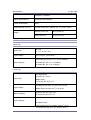
Environment
1.
Temperature Range: 10°C to 32°C (50°F to 89.6°F)
2.
Humidity Range: 15% to 80% RH
3.
Ambient Illumination: Less than 1500 lux (do not expose to direct sunlight)
4.
Ventilation: 3 times/hr/person or more
5.
Do not let the machine get exposed to the following:
1) Cool air from an air conditioner
2) Heat from a heater
6.
Do not install the machine in areas that are exposed to corrosive gas.
7.
Install the machine at locations lower than 2,500 m (8,200 ft.) above sea level.
8.
Install the machine on a strong, level base. (Inclination on any side must be no more than
5 mm.)
9.
Do not install the machine in areas that get strong vibrations.
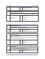
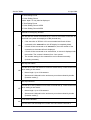
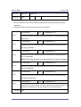
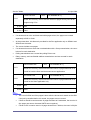
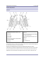
Machine Level
Front to back: Within 5 mm (0.2")
Right to left: Within 5 mm (0.2")
1
Installation
21-Apr-2006
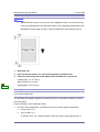
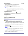
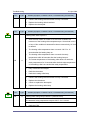
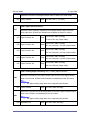
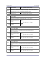
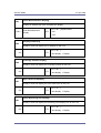
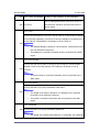
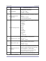
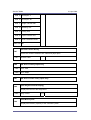
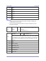
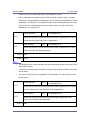
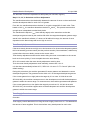
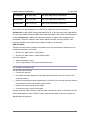
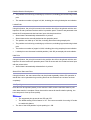
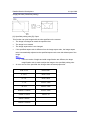
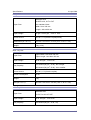
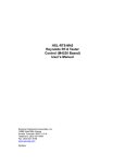
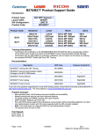
Machine Space Requirements
This machine, which uses high voltage power sources, can generate ozone gas.
High ozone density is harmful to human health. Therefore, the machine must be
installed in a well-ventilated room.
A: Over 100 mm (3.9")
B: Over 100 mm (3.9")
C: Over 100 mm (3.9")
D: Over 100 mm (3.9")
Put the machine near the power source with the clearance shown above.
Power Requirements
1.
Insert the plug firmly in the outlet.
Do not use an outlet extension plug or cord.
Ground the machine.
Input voltage level:
120 V, 60 Hz: More than 12 A
220 V to 240 V, 50 Hz/60 Hz: More than 8 A
2.
Permissible voltage fluctuation: ±10 %
3.
Do not put things on the power cord.
2
Installation
21-Apr-2006
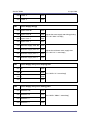
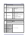
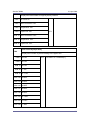
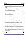
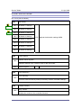
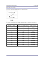
Optional Unit Combinations
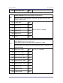
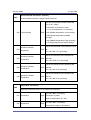
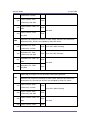
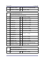
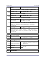
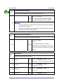
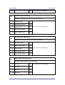
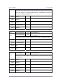
Machine Options
No.
Options
1
2-tray paper feed unit
2
Large capacity tray
3
Platen cover
4
ARDF
5
1-bin tray unit
6
Bridge unit
7
Shift tray
8
1000-sheet booklet finisher
9
*Punch kit (3 types)
10
1000-sheet finisher
11
500-sheet finisher
Remarks
One from No.1 or No.2
One from No.3 or No.4
-
One from No.6 or No.7
One from No.8, No.10 or No.11;
Requires No.6 and one from No.1 and No.2.
No. 8 required; One of the three types
One from No.8, No.10 or No.11;
Requires No.6 and one from No.1 and No.2.
One from No.8, No.10 or No.11;
Requires No.6.
*: Child options (Child options require a parent option.)
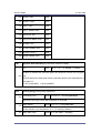
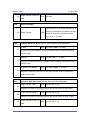
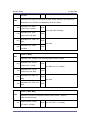
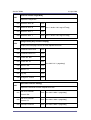
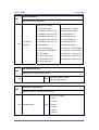
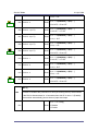
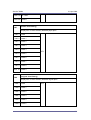
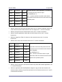
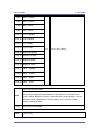
Controller Options
No.
Options
1
IEEE 1394
2
USB Host Interface Unit
3
IEEE 802.11b
4
IEEE 1284
Remarks
One from the two (I/F Slot A)
One from the three (I/F Slot B)
3
Installation
21-Apr-2006
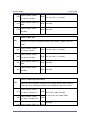
5
Bluetooth
6
File Format Converter
7
PostScript 3
8
PictBridge Option
9
Data Overwrite Security Unit
11
Browser Unit
SD card slot 3 (during installation only)
12
Copy Data Security Unit
-
I/F Slot C
Requires fax unit option (B786)
One from the three (SD card slot 2)
4
Installation
21-Apr-2006
Copier Installation
Make sure that the image transfer belt is in its correct position before you move the
machine. Otherwise, the image transfer belt and the black PCU can be damaged.
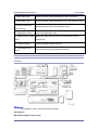
Power Sockets for Peripherals
Rating voltage for peripherals.
Make sure to plug the cables into the correct sockets.
5
Installation
21-Apr-2006
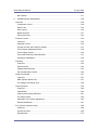
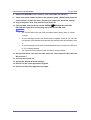
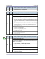
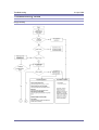
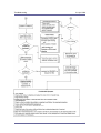
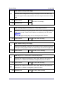
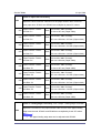
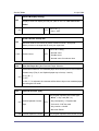
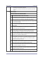
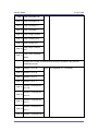
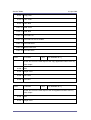
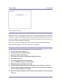
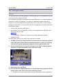
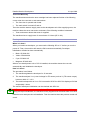
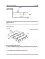
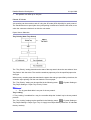
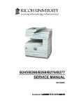
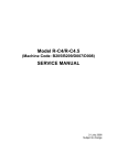
Installation Flow Chart
This flow chart shows the best procedure for installation.
You need the optional paper tray unit or the LCT if you want to install the finisher (B408 or
B793).
The punch unit is for 1000-sheet booklet finisher (B793).
6
Installation
21-Apr-2006
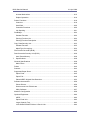
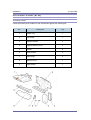
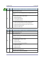
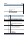
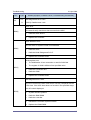
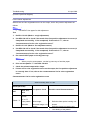
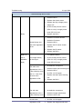
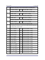
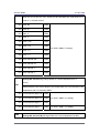
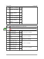
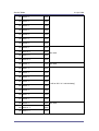
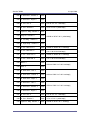
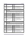
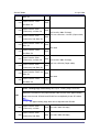
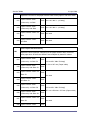
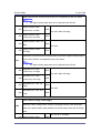
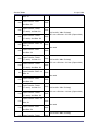
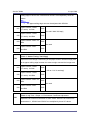
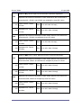
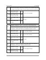
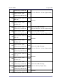
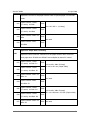
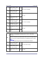
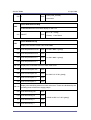
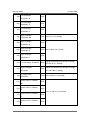
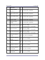
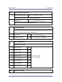
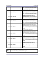
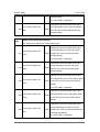
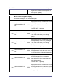
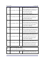
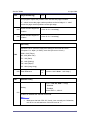
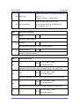
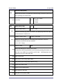
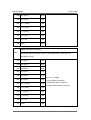
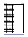
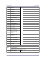
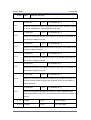
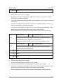
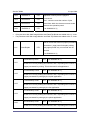
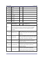
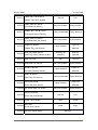
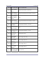
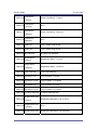
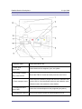
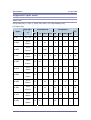
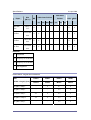
Accessory Check
Check the quantity and condition of these accessories.
Description
Q'ty
Destination
1.
Operating Instruction - Troubleshooting
1
-57 -29 -58 -21 -19
2.
Operating Instruction - About This Machine
1
-57 -29 -58 -21 -19
3.
Operating Instruction - Security
1
-57 -29 -58 -21 -19
4.
Operation Instruction - Quick Reference Guide
1
-29 -21 -19
5.
Operation Instruction - Printer Quick Reference
1
-29 -21 -19
6.
Operation Instruction - Scanner Quick Reference
1
-29 -21 -19
7.
CD-ROM - Instruction
1
-29
8.
CD-ROM - Printer Instruction - RIC
1
-67 -29 -26
9.
CD-ROM - Printer Instruction - NRG
1
-67
10.
CD-ROM - Printeer Instruction - LAN
1
-67
11.
CD-ROM - Scanner Instruction - RIC
1
-67 -29 -26
12.
CD-ROM - Scanner Instruction - NRG
1
-67
13.
CD-ROM - Scanner Instruction - LAN
1
-67
14.
Model Name Decal
1
-57 -67 -29 -58
15
Stamp
1
-57 -29 -28 -19 -58
16
Cloth Holder
1
17
Exposure Glass Cleaning Cloth
1
18
Rivet
2
-57 -67 -29 -28 -21 -19
-58 -26
-57 -67 -29 -28 -21 -19
-58 -26
-57 -67 -29 -28 -21 -19
-58 -26
7
Installation
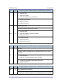
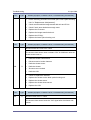
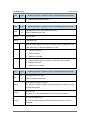
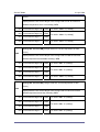
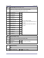
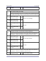
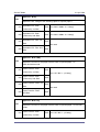
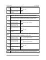
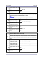
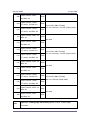
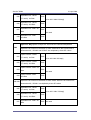
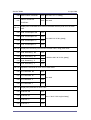
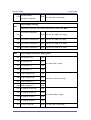
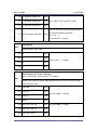
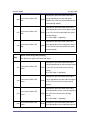
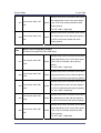
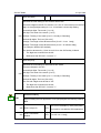
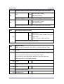
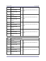
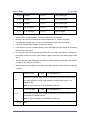
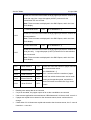
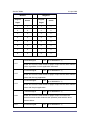
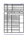
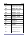
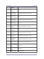
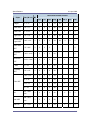
21-Apr-2006
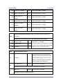
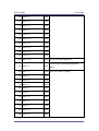
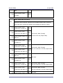
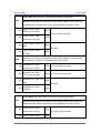
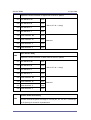
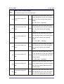
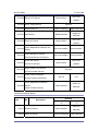
Description
Q'ty
Destination
-57 -67 -29 -28 -21 -19
19
Operating Instructions Holder
1
20
Ferrite Core
1
21
Power Supply Cord
1
22
Cover
1
23
Decal - Paper Size
1
24
Emblem Cover
1
-57 -67 -29 -58
25
Sheet - Eula: 16 Languages
1
-57 -67 -29 -26 -58
26
Sheet - Caution 16 Languages
1
-57 -67 -29 -26 -58
27
Decal - Safety Sheet
1
-67 -26
28
Decal - Caution - Original
1
-67 -29 -28 -26 -57 -58
29
Sheet Data
1
-67 -29 -28 -26 -21
30
Decal - Caution - Inkjet
1
-67 -26 (14 Lang.)
31
Sheet - Caution - Security Reference
1
-29
32
Warranty Sheet (Chinese)
1
-21
33
Sheet - Name - Tel
1
-21
-58 -26
-57 -67 -29 -28 -21 -19
-58 -26
-57 -67 -29 -28 -21 -19
-58
-57 -67 -29 -28 -21 -19
-58 -26
-57 -67 -29 -28 -21 -19
-58 -26
8
Installation
21-Apr-2006
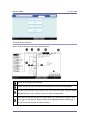
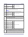
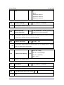
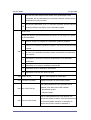
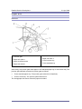
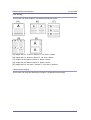
Installation Procedure
Remove the tape from the development units before you turn the main switch
on. The development units can be severely damaged if you do not remove the
tape.
Put the machine on the paper tray unit or the LCT first if you install an optional paper tray unit
or the optional LCT at the same time. Then install the machine and other options.
Keep the shipping retainers after you install the machine. You may need them in the
future if you transport the machine to another location.
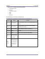
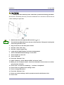
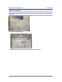
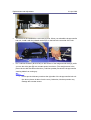
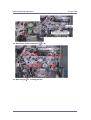
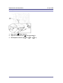
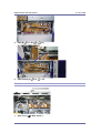
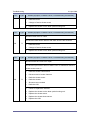
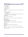
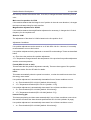
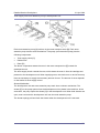
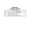
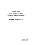
Tapes and Retainers
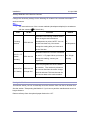
1.
Remove all the tapes and retainers on the machine.
2.
Remove all the tapes and retainers in trays 1 and 2, and then take out the power
cord from tray 1 (if applicable).
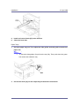
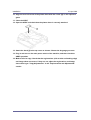
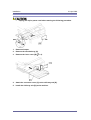
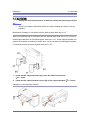
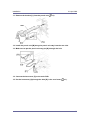
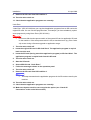
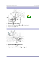
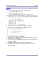
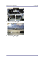
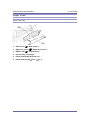
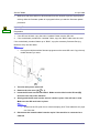
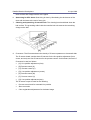
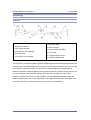
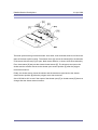
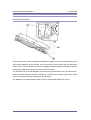
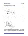
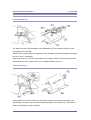
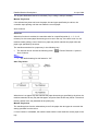
3.
Remove the scanner unit stay [A].
4.
Open the front door [B], and then remove the jam location sheet [C].
5.
Keep the scanner unit stay [A] inside the front door [B].
6.
Reattach the jam location sheet.
7.
Close the front door.
9
Installation
21-Apr-2006
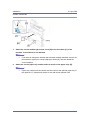
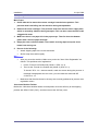
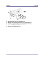
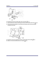
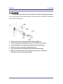
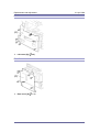
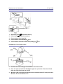
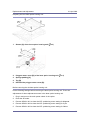
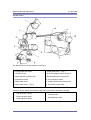
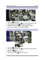
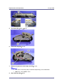
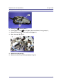
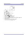
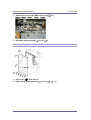
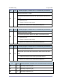
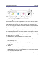
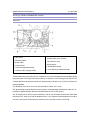
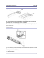
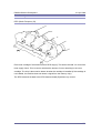
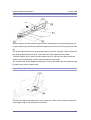
Developer and Toner Bottles
1.
Open the front door [A].
GSA model (-58) and EU models (-67/-26) do not require steps from 2 to 7. Skip to step 8 if
you install these models.
1.
Remove the stopper [B] (
2.
x 1).
This stopper locks the drum positioning plate lever.
Release the image transfer belt lever [C], and turn the drum positioning plate lever
[D] counterclockwise.
3.
Open the drum positioning plate [E].
4.
Remove all tapes [F] from the four development units.
When you remove the tape from the development unit, hold the development
unit with your hand, and then pull the tape.
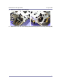
5.
Close the drum positioning plate. Then lock the image transfer belt lever and turn
the drum positioning plate lever clockwise.
6.
Lock the drum positioning plate lever with the stopper [B] (
7.
Shake each toner bottle five or six times.
x 1).
10
Installation
21-Apr-2006
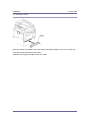
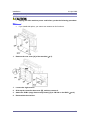
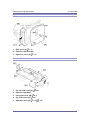
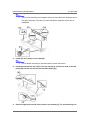
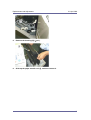
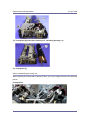
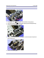
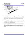
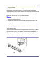
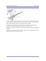
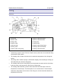
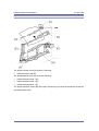
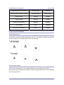
8.
Install each toner bottle [G] in the machine.
9.
Close the front door.
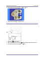
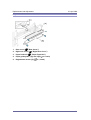
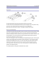
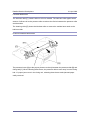
Paper Trays
1.
Pull each paper tray out. Then adjust the side guides and end guide to match the
paper size.
To move the side guides, first pull out the tray fully. Then push down the green
lock at the rear inside the tray.
2.
Pull out the feeler [A] for the output tray full detection mechanism.
11
Installation
21-Apr-2006
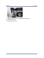
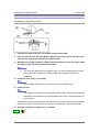
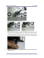
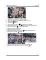
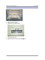
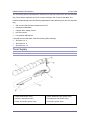
Emblem and Decals
1.
Attach the correct emblem [A] and the cover [B] to the front door [C] of the
machine, if the emblem is not attached.
If you want to change the emblem that has been already attached, remove the
panel with an object (not a sharp object) as shown [D], and then install the
correct emblem.
2.
Attach the correct paper tray number and size decals to the paper trays [E].
Paper tray number and size decals are also used for the optional paper tray or
the optional LCT. Keep these decals for use with these optional units.
12
Installation
21-Apr-2006
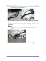
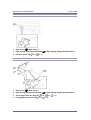
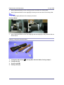
Fire Prevention Cover
When the copier is installed on the floor without the optional paper tray unit or a table, the
cover [A] must be attached to the copier.
Install the cover [A] at the right side of the copier.
13
Installation
21-Apr-2006
Manual Pocket Attachment
1.
Attach the manual pocket [A] to the left side of the copier (snap rivet x 2).
2.
If any finisher has been installed, attach the manual pocket [B] to the rear side of a
finisher (snap rivet x 2).
Initialize the Developer
1.
Plug in the machine.
2.
Make sure that the platen or ARDF is closed and the main power is turned off.
3.
Turn the main power switch on. The machine automatically starts the initialization
procedure. The Start button LED ( ) turns green when this procedure has
finished.
4.
Make copies of image samples (text, photo, and text/photo modes).
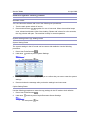
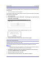
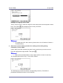
5.
Do the Automatic Color Calibration process (ACC) as follows:
6.
1.
Print the ACC test pattern (User tools > Maintenance > ACC > Start).
2.
Put the printout on the exposure glass.
3.
Put 10 sheets of white paper on top of the test chart.
4.
Close the ARDF or the platen cover.
5.
Press “Start Scanning” on the LCD panel. The machine starts the ACC.
Check that the sample image has been copied normally.
14
Installation
21-Apr-2006
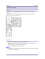
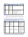
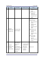
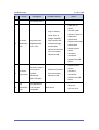
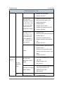
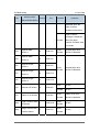
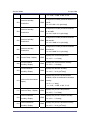
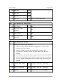
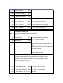
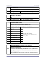
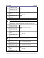
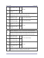
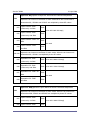
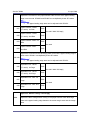
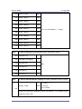
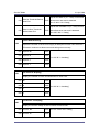
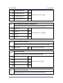
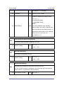
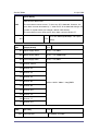
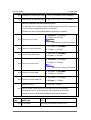
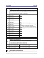
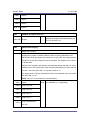
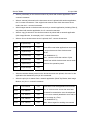
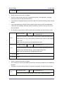
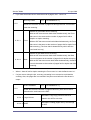
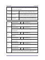
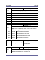
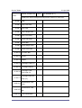
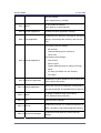
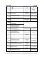
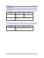
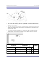
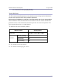
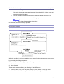
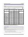
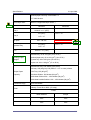
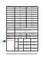
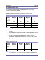
Settings Relevant to the Service Contract
Change the necessary settings for the following SP modes if the customer has made a
service contract.
You must select one of the counter methods (developments/prints) in accordance
with the contract (
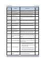
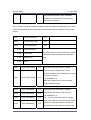
Item
SP5-045-001).
SP No.
Function
Default
Specifies if the counting method used in
meter charge mode is based on
Counting
method
SP5-045-001
developments or prints. NOTE: You can
“0”:
set this one time only. You cannot
Developments
change the setting after you have set it
for the first time.
Specifies whether the counter is doubled
A3/11" x 17"
double
SP5-104-001
counting
for A3/11" x 17" paper. When you have to “No”: Single
change this setting, contact your
counting
supervisor.
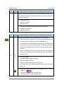
5812-002 programs the service station
Service Tel.
SP5-812-001
No. Setting
through 004
fax number. The number is printed on
the counter list when the meter charge
mode is selected. This lets the user fax
the counter data to the service station.
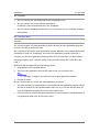
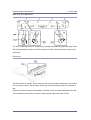
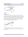
Moving the Machine
This section shows you how to manually move the machine from one floor to another floor.
See the section “Transporting the Machine” if you have to pack the machine and move it a
longer distance.
Remove all trays from the optional paper feed unit or LCT.
15
Installation
21-Apr-2006
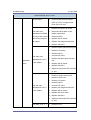
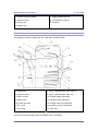
Transporting the Machine
Main Frame
1.
Do SP 4806-001 to move the scanner carriage from the home position. This
prevents dust from falling into the machine during transportation.
2.
Remove the toner cartridges. This prevents toner flow into the toner supply tube,
which is caused by vibration during transport. This can also cause the tube to be
clogged with toner.
3.
Make sure there is no paper left in the paper trays. Then fix down the bottom
plates with a sheet of paper and tape.
4.
Empty the toner collection bottle. Then attach securing tape to stop the toner
bottle from coming out.
5.
Do one of the following:
Attach shipping tape to the covers and doors.
Shrink-wrap the machine tightly.
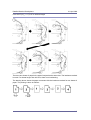
After you move the machine, Make sure you do the "Auto Color Registration" as
follows. This optimizes color registration.
1.
Do the "Forced Line Position Adj. Mode c" (SP2-111-3).
2.
Then do the "Forced Line Position Adj. Mode a" (SP2-111-1).
To check if SP 2-111-1 was successful, watch the screen during the process. A
message is displayed at the end. Also, you can check the result with SP
2-194-10 to -12.
Make sure that the side fences in the trays are correctly positioned to prevent color
registration errors.
1000-sheet Booklet Finisher
Before the 1000-sheet booklet finisher is transported, move the shift tray to the shipping
position with SP6137-003 ("ON"), and then remove the shift tray cover.
16
Installation
21-Apr-2006
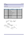
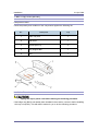
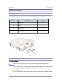
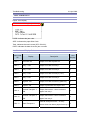
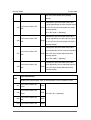
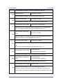
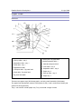
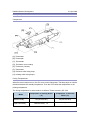
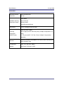
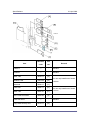
Paper Feed Unit (B800)
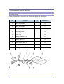
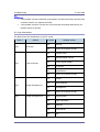
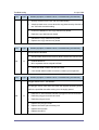
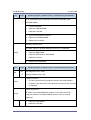
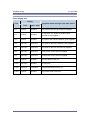
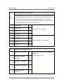
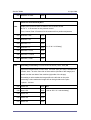
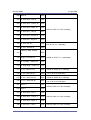
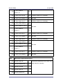
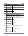
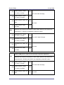
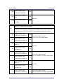
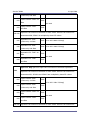
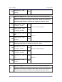
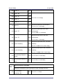
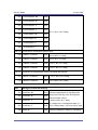
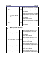
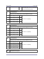
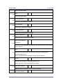
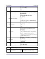
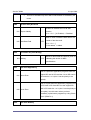
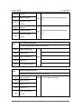
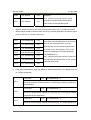
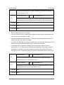
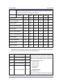
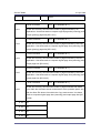
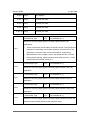
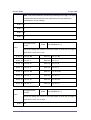
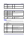
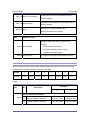
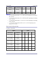
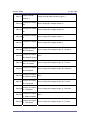
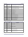
Accessory Check
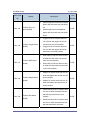
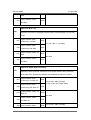
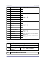
Check the quantity and condition of the accessories against the following list.
No.
Description
Q’ty
1
Caster stand
6
2
Securing bracket
2
3
Screw (M3x6 x 6, M4x10 x 2)
8
4
Spring Washer Screw
1
5
Rear stand cover
1
6
Left stand cover
1
7
Front stand cover
1
17
Installation
21-Apr-2006
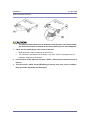
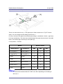
Installation Procedure
Turn off the main switch of the copier and unplug the power cord before you
start the installation procedure.
You need two or more persons to lift the copier. The copier is highly unstable
when lifted by one person, and may cause human injury or property damage.
Do not lift the copier with the paper feed unit installed. Otherwise, the handle
and grips may be damaged.
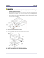
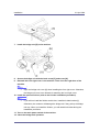
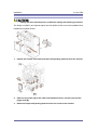
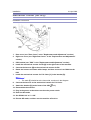
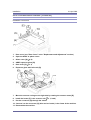
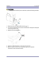
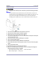
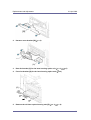
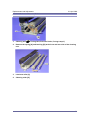
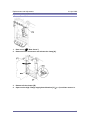
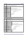
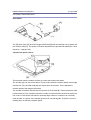
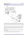
1.
Remove all tape on the paper feed unit.
2.
Remove the paper trays and remove all tape and padding.
3.
Grasp the handle [A] and grips [B] of the machine.
4.
Lift the copier and install it on the paper feed unit [C].
18
Installation
21-Apr-2006
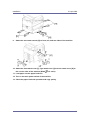
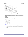
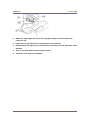
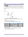
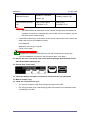
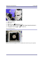
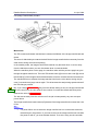
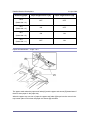
5.
Remove tray 2 of the machine.
6.
Fasten the spring washer screw [D], using the cutout in the securing bracket [E]
as a tool.
7.
Reinstall tray 2.
8.
Attach the securing brackets [E] (M4x10
x 1 each).
One of the securing brackets is used as a securing tool (the cutout [F] is used in
step 6). But the cutout [G] is for attaching the tray heater. Therefore, attach the
securing brackets [E] after installing the tray heater if you will install the tray
heater.
19
Installation
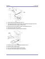
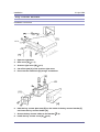
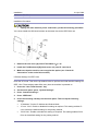
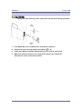
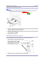
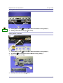
9.
21-Apr-2006
Attach the two caster stands [H] to front, left, and rear sides of the machine.
10. Attach the front stand cover [I], right stand cover [J] and rear stand cover [K] to
the correct sides of the machine (M3x6
x 2: each).
11. Load paper into the paper feed unit.
12. Turn on the main power switch of the machine.
13. Check the paper feed unit operation and copy quality.
20
Installation
21-Apr-2006
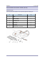
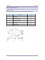
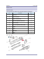
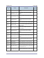
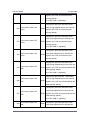
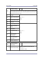
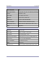
LCT (B801)
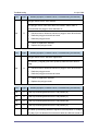
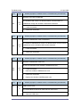
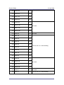
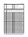
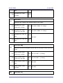
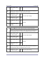
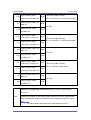
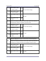
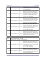
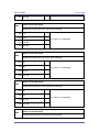
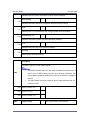
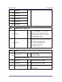
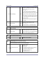
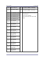
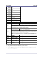
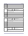
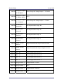
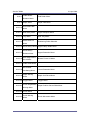
Accessory Check
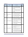
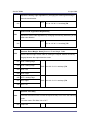
Check the quantity and condition of the accessories against the following list.
No.
Description
Q’ty
1
Caster stand
6
2
Securing bracket
2
3
Screw (M3x6 x 6, M4x10 x 2)
8
4
Spring washer screw
1
5
Rear stand cover
1
6
Right stand cover
1
7
Front stand cover
1
21
Installation
21-Apr-2006
Installation Procedure
Turn off the main switch of the copier and unplug the power cord before you
start the installation procedure.
You need two or more persons to lift the copier. The copier is highly unstable
when lifted by one person, and may cause human injury or property damage.
Do not lift the copier with the paper feed unit installed. Otherwise, the handle
and grips may be damaged.
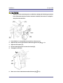
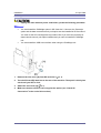
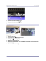
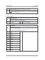
1.
Remove all tapes and retainers in the LCT.
2.
Grasp the handle [A] and grips [B] of the machine.
3.
Lift the copier and install it on the LCT [C].
22
Installation
21-Apr-2006
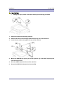
4.
Remove tray 2 of the machine.
5.
Fasten the spring washer screw [D], using the cutout in the securing bracket [E]
as a tool.
6.
Reinstall tray 2.
7.
Attach the securing brackets [E] (M4x10
x 1each).
One of the securing brackets is used as a securing tool (the cutout [F] is used in
step 6). But the cutout [G] is for attaching the tray heater. Therefore, attach the
securing brackets [E] after installing the tray heater if you will install the tray
heater.
23
Installation
21-Apr-2006
8.
Attach the two caster stands [H] to the front, right, and rear sides of the machine.
9.
Attach the front stand cover [I], right stand cover [J] and rear stand cover [K] to
the correct sides of the machine (M3x6
x 2 each).
10. Load paper into the LCT.
11. Turn on the main power switch of the machine.
12. Check the LCT operation and copy quality.
24
Installation
21-Apr-2006
Auto Reverse Document Feeder (B789)
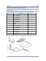
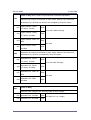
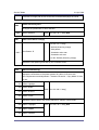
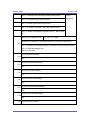
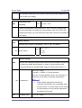
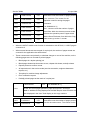
Component Check
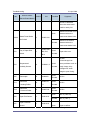
Check the quantity and condition of the components against the following list.
No.
Description
Q’ty
1
ARDF
1
2
Stamp Cartridge
1
3
Screwdriver Tool
1
4
Knob Screw
2
5
Stud Screw
2
6
Attention Decal – Top Cover
1
25
Installation
21-Apr-2006
Installation Procedure
Unplug the copier power cord before starting the following procedure.
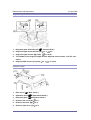
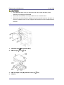
1.
Remove all tapes and shipping retainers.
2.
Remove the two screws already installed at the top rear of the machine.
3.
Insert the two stud screws [A] on the top of the machine.
4.
Mount the ARDF [B] by aligning the screw keyholes [C] in the ARDF support plate
over the stud screws.
5.
Slide the ARDF toward the front of the machine.
6.
Secure the ARDF with the two knob screws [D].
26
Installation
7.
Remove two screws [E] from the bottom of the ARDF.
8.
Install the stamp cartridge [F] in the ARDF.
9.
Peel off the platen sheet [G] and place it on the exposure glass.
21-Apr-2006
27
Installation
21-Apr-2006
10. Align the rear left corner of the platen sheet with the corner [H] on the exposure
glass.
11. Close the ARDF.
12. Open the ARDF and check that the platen sheet is correctly attached.
13. Attach the decal [I] to the top cover as shown. Choose the language you want.
14. Plug in and turn on the main power switch of the machine, and then check the
ARDF operation.
15. Make a full size copy. Check that the registrations (side-to-side and leading edge)
and image skew are correct. If they are not, adjust the registrations and image
skew referring to "Copy Adjustments" in the "Replacements and Adjustments”
section.
28
Installation
21-Apr-2006
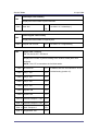
1-Bin Tray Unit (B790)
Component Check
Check the quantity and condition of the components against the following list.
No.
Description
Q’ty
1
1-Bin Tray Unit
1
2
End-fence
1
3
Screws (M3 x 8)
3
4
Tray Support Bar
1
5
Tray
1
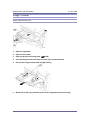
Installation Procedure
Unplug the copier power cord before starting the following procedure.
If the bridge unit (B227) has already been installed in the machine, remove it before installing
1-bin tray unit (B790). This will make it easier for you to do the following procedure.
29
Installation
21-Apr-2006
1.
Remove all tapes.
2.
Open the duplex unit at the right side of the machine.
3.
Remove the front right cover [A] (
4.
Remove the cover [B].
5.
Remove the tray [C].
6.
Remove the paper exit unit [D] (
1.
Install the 1-bin tray unit [E] (
x 1,
x 1).
x 1).
x 1).
30
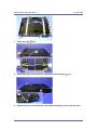
Installation
2.
21-Apr-2006
Attach the tray support bar [F] to the tray [G] as shown, and then attach the
end-fence [H].
3.
Install the tray [G] (with the tray support bar) in the machine.
4.
Reinstall the front right cover in the machine, and then close the right door of the
machine.
5.
Turn on the main power switch of the machine.
6.
Check the 1-bin tray unit operation.
31
Installation
21-Apr-2006
Shift Tray Unit (B791)
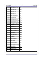
Component Check
Check the quantity and condition of the components against the following list.
No.
Description
Q’ty
1
Shift Tray Unit
1
2
Paper Guide - Large
1
3
Paper Guide - Small
2
4
Knob Screw
1
5
Connector Cover
1
32
Installation
21-Apr-2006
Installation Procedure
Unplug the copier power cord before starting the following procedure.
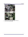
1.
Remove all tapes.
2.
Remove the standard tray [A].
3.
Remove the inner cover [B] (
4.
Attach the connector cover [C] to the shift tray unit [D].
5.
Install the shift tray unit [D] to the machine.
x 1).
33
Installation
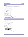
6.
Open the left side door [E] of the shift tray unit.
7.
Attach the shift tray unit to the machine with the knob screw [F].
8.
Install the large paper guide [G] and two small paper guides [H].
9.
Turn on the main power switch of the machine.
21-Apr-2006
10. Check the shift tray unit operation.
34
Installation
21-Apr-2006
Bridge Unit (B227)
Component Check
Check the quantity and condition of the components against the following list.
No.
Description
Q’ty
1
Bridge Unit
1
2
Screw
1
3
Knob screw
1
4
Holder bracket
1
Installation Procedure
Unplug the copier power cord before starting the following procedure.
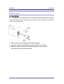
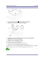
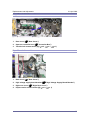
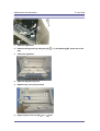
1. If you will install the 1-bin tray (B790) in the machine, install the 1-bin tray before
you installing the bridge unit (B227). This will make it easier for you to do the
following procedure.
2. If you will install a finisher (B408, B792 or B793) in the machine, install the finisher
35
Installation
21-Apr-2006
after you install the bridge unit (B227).
1.
Remove all tapes.
2.
If the sensor feeler [A] is out, fold it into the machine.
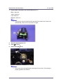
3.
Open the duplex unit at the right side of the machine.
4.
Remove the standard tray [B].
5.
Remove the front right cover [C] (
x 1).
6.
Remove the connector cover [D] (
x 1).
36
Installation
21-Apr-2006
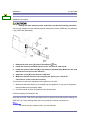
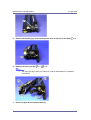
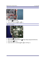
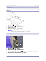
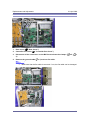
7.
Install the bridge unit [E] in the machine.
8.
Secure the bridge unit with the knob screw [F] and screw [G].
9.
Reinstall the front right cover in the machine. Then close the right door of the
machine.
Open the bridge unit cover [H] when installing the front right cover. Otherwise,
the bridge unit cover is an obstacle for attaching the front right cover.
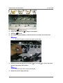
10. Install the optional finisher (refer to the finisher installation procedure).
If you will not install the finisher at this time, install the holder bracket [I].
Otherwise, the customer will damage the bridge unit if they pull up the bridge
unit tray. When you install the finisher, you will need this bracket during the
installation procedure.
11. Turn on the main power switch of the machine.
12. Check the bridge unit operation.
37
Installation
21-Apr-2006
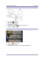
500-Sheet Finisher (B792)
Accessory Check
Check the quantity and condition of the accessories against the following list.
No.
Description
Q’ty
1
Output Tray
1
2
Unit Holder
1
3
Support Bracket
2
4
Support Bracket Cover
2
5
Screws
6
6
Knob Screws
4
7
Snap Rings
2
8
Bracket Cover
1
9
Paper Guide
1
38
Installation
21-Apr-2006
Installation Procedure
Unplug the main machine power cord before starting the following procedure.
Before you install the 500-sheet finisher, the optional bridge unit (B227) must be
installed
Beforehand: Installing on a machine with the optional paper feed unit or LCT
When you install this unit on a machine with the optional paper feed unit or LCT, you must
install support brackets on the optional paper feed unit or LCT. These support brackets can
prevent the machine from falling to the left side. You do not need to install support brackets
on machines without the optional paper feed unit or LCT.
1.
Install the two support brackets [A] on the left side of the machine
(
2.
x 1 each).
Install the two support bracket covers [B] on the support brackets (
x 1 each).
Installation of the 500-Sheet Finisher
39
Installation
21-Apr-2006
1.
Unpack the finisher and remove all tapes and retainers.
2.
Attach the paper guide [A].
3.
Attach the unit holder [B] and the holder bracket [C] (knob screw x 4).
The holder bracket [C] must be placed outside the unit holder [B]. The holder
bracket is provided with the bridge unit (B227).
4.
Install the 500-sheet finisher [D] on the machine (
x 1).
40
Installation
21-Apr-2006
5.
Attach the bracket cover [E].
6.
Install the output tray [F] on the 500-sheet finisher (2 snap rings).
7.
Pull out the tray extension [G] of the bridge unit.
8.
Turn on the main power switch, and then check the finisher operation.
41
Installation
21-Apr-2006
1000-Sheet Finisher (B408)
Accessory Check
Check the quantity and condition of the accessories against the following list.
No.
Description
Q’ty
B230/B237
1
Front Joint Bracket
1
O
2
Rear Joint Bracket
1
---
3
Rear Joint Bracket
1
O
4
Grounding Plate
1
O
5
Copy Tray
1
O
6
Staple Position Decal
1
O
7
Screw - M4 x 14
4
O
8
Knob Screw - M4 x 10
1
O
9
Screw - M3 x 8
1
O
10
Knob Screw - M3 x 8
1
O
O = Necessary, --- = Not necessary
42
Installation
21-Apr-2006
Installation Procedure
Unplug the main machine power cord before starting the following procedure.
If this finisher will be installed on the B230 or B237 copier, the following options must be
installed before installing this finisher.
- Bridge Unit (B227)
- Paper Feed Unit (B800) or LCT (B801)
1.
Unpack the finisher, and then remove the stopper [A] and tapes (
2.
Install the front joint bracket [B], holder bracket [C] (
bracket [D] (
x 1).
x 2 - M4 x 14), and rear joint
x 2 - M4 x 14).
The holder bracket [C] must be placed outside the front joint bracket [B]. The
holder bracket is provided with the bridge unit (B227).
43
Installation
3.
21-Apr-2006
Install the grounding plate [E] on the finisher (
x 2 - M3 x 8).
Use the screw removed in step 1 and the screw from the accessory box.
4.
Open the front door [F] of the finisher, and then pull the locking lever [G].
5.
Align the finisher on the joint brackets, and lock it in place by pushing the locking
lever.
6.
Secure the locking lever (1 knob screw - M3 x 8).
7.
Close the front door.
8.
Install the copy tray [H] (1 knob screw - M4 x 10).
9.
Connect the finisher cable [I] to the main machine below the right rear handle.
10. Attach the staple position decal [J] to the ARDF as shown.
11. Turn on the main power switch and check the finisher operation.
44
Installation
21-Apr-2006
1000-Sheet Booklet Finisher (B793)
Accessory Check
Check the quantity and condition of the accessories against the following list.
No.
Description
Q’ty
1
Rear Joint Bracket
1
2
Front Joint Bracket
1
3
Grounding Plate
1
4
Upper Output Tray
1
5
Cushion
2
6
Lower Output Tray
1
7
Short Knob Screw
1
8
Long Knob Screw
1
9
Screw (M3 x 8)
2
10
Screw (M4 x 14)
4
45
Installation
21-Apr-2006
Installation Procedure
Unplug the main machine power cord before starting the following procedure.
The bridge unit (B227) and optional paper feed unit (B800 or B801) must be installed before
installing this finisher (B793).
1.
Unpack the finisher and remove all tapes and packing materials from the finisher.
2.
Open the front door [A] of the 1000-sheet booklet finisher, and then pull out the
jogger unit [B].
3.
Remove all tapes and packing materials from the inside of the finisher.
46
Installation
4.
21-Apr-2006
Attach the cushions [C] to the finisher.
Make sure that the cushions are placed within 0 to 1 mm [D] from the edge of the
cover or frame.
5.
Install the ground plate [E] on the finisher (
6.
Attach the rear joint bracket [F]
x 2; M3 x 8).
( x 2, M4 x 14).
7.
Attach the front joint bracket [G] and the holder bracket [H] (
x 2; M4 x 14).
The holder bracket [H] must be placed outside the front joint bracket [G]. The
holder bracket is provided with the bridge unit (B227).
47
Installation
21-Apr-2006
8.
Pull the lock lever [I] (Long knob screw x 1).
9.
Slowly push the finisher to the left side of the machine, keeping its front door
open until the brackets [J] [K] go into their slots.
10. Push the lock lever [I], and then secure it (Long knob screw x 1).
11. Close the front door of the finisher.
12. Connect the finisher connector [L] to the machine.
13. Install the upper output tray [M] (Short knob screw x 1).
14. Install the lower output tray [N].
15. Turn on the main power switch of the machine.
16. Check the 1000-sheet booklet finisher operation.
48
Installation
21-Apr-2006
Punch Unit
Component Check
Check the quantity and condition of the components against the following list.
No.
Description
Q’ty
1
Punch Unit
1
2
Punch Drive Motor
1
3
Hopper Full Sensor Arm
1
4
Sub-scan Registration Sensor Unit
1
5
Punch Unit Stay
1
6
Sub-scan Registration Sensor Guide
1
7
Hopper
1
8
Screw
1
9
Step Screw
1
10
Spring
1
49
Installation
21-Apr-2006
Installation
Unplug the main machine power cord before starting the following procedure.
If the 1000-sheet booklet finisher has been installed, disconnect it and pull it
away from the machine.
1.
If the finisher is connected to the machine, disconnect it.
2.
Open the top cover [A] and then release the guide arm [B] (
3.
Open the front door [C].
4.
Pull the hook [D] up then remove the knob [E].
5.
Timing belt cover [F].
6.
Rear cover of the 1000-sheet booklet finisher [G] (
x 1).
x 2).
50
Installation
7.
Cover bracket [H] ( x 1)
8.
Remove the paper guide plate [I] from the rear side (
9.
Install the punch unit stay [J] from the front side (
21-Apr-2006
x 4).
x 3).
10. Install the sub-scan registration sensor guide [K] from the top (
x 1).
51
Installation
11. Remove the bracket [L] from the punch unit (
21-Apr-2006
x 1).
12. Install the punch unit [M] along the punch unit stay from the rear side.
13. Make sure to put the punch unit stay pin [N] through the hole
14. Connect the harnesses [P] to the main PCB.
15. Put the harnesses [Q] through the hole [R] in the rear frame (
x 1).
52
Installation
21-Apr-2006
16. Install the punch drive motor [S] on the rear frame (
x 2).
17. Connect the drive motor harness [T] to the harness from the punch unit (
x 1).
18. Connect the home position sensor harness from the punch unit to the home
position sensor [U].
19. Install the sub-scan registration sensor unit [V] from the rear side (
20. Route and connect the harnesses as shown (
x 2).
x 2).
53
Installation
21-Apr-2006
21. Install the hopper full sensor arm [W] (
x 1, spring x 1).
22. Connect the harness from the sub-scan registration sensor unit to the hopper full
sensor [X].
23. Install the hopper [Y] from the front side.
24. Reinstall the timing belt cover and knob.
25. Reinstall the rear cover (
x 2).
26. Close the front door and top cover.
27. Install the 1000-sheet booklet finisher on the copier.
28. Plug in and turn on the main power switch.
29. Check the 1000-sheet booklet finisher operation.
54
Installation
21-Apr-2006
Mechanical Counter (NA Only)
Installation Procedure
1.
Rear cover (see "Rear Cover" in the "Replacement and Adjustment" section)
2.
Right rear cover (see "Right Rear Cover" in the "Replacement and Adjustment"
section)
3.
PSU bracket (see "PSU" in the "Replacement and Adjustment" section)
4.
Install the mechanical counter for Bk [A] in the right frame of the machine.
5.
Connect the harness [B] to the mechanical counter for Bk.
6.
Route the harness as shown with clamps, and then connect it to CN260 on the
IOB.
7.
Install the mechanical counter for Full Color [C] in the bracket [D].
The mark [E] should be at the lower side, as shown in the diagram.
8.
Connect the harness to the mechanical counter for Full Color.
9.
Attach the bracket [D] to the frame of the IOB (
x 1).
10. Reassemble the machine.
11. Plug in the power cord and turn on the main power switch.
12. Enter the SP mode.
13. Set SP5987-001 to "1: ON".
14. Exit the SP mode, and then turn the machine off and on.
55
Installation
21-Apr-2006
Key Counter Bracket
Installation Procedure
1.
Open the right door.
2.
Rear cover [A] (
3.
Scanner right cover [B] (
4.
Cut off the part [C] of the scanner right cover.
5.
Punch out the small hole [D] using a screwdriver.
6.
Hold the key counter plate nuts [E] on the inside of the key counter bracket [F]
x 7)
x 2)
and insert the key counter holder [G].
7.
Secure the key counter holder to the bracket ( x 2).
8.
Install the key counter cover [H] (
x 2).
56
Installation
9.
21-Apr-2006
Connect the harness to the connector [I] inside the machine.
10. Install the key counter.
11. Reassemble the machine.
57
Installation
21-Apr-2006
Key Counter Interface Unit
Installation Procedure
1.
Rear cover (see "Rear Cover" in the "Replacement and Adjustment" section)
2.
PSU bracket (see "PSU" in the "Replacement and Adjustment" section)
3.
Install the four stud stays [A] in the PSU bracket.
4.
Install the key counter interface board [B] to the PSU bracket with the four stud
stays.
5.
Connect the harness [C] between CN252 on the IOB and the connector of the key
counter interface board.
6.
Cut off the part [D] of the rear cover.
7.
Connect the harness to the key counter interface board, and install the rear cover.
8.
Connect the harness to a counter device.
58
Installation
21-Apr-2006
Anti-Condensation Heater (Scanner)
Installation Procedure
1.
Rear cover (see "Rear Cover" in the "Replacement and Adjustment" section)
2.
Open the ARDF or platen cover.
3.
Glass cover [A] ( x 4)
4.
ARDF exposure glass [B]
5.
Rear scale [C] (
6.
Exposure glass with left scale [D]
7.
Move the scanner carriage to the right side by rotating the scanner motor [E].
8.
Install the heater [F] in the scanner unit (
9.
Put the connector [G] through the cutout.
x 3)
x 1, hook)
10. Connect it to the connector [H] (blue and red cords) in the frame of the machine.
11. Reassemble the machine.
59
Installation
21-Apr-2006
Tray Heater
Installation Procedure
1.
Remove trays 1 and 2 from the machine.
2.
Remove the connector cover [A] (
3.
Connect the connector [B] of the heater to the connector of the main machine.
4.
Install the heater [C] inside the machine (
5.
Reassemble the machine.
x 1).
x 1)
60
Installation
21-Apr-2006
Controller Options
Overview
This machine has I/F card slots and SD card slots for optional I/F connections and
applications.
After you install an option, check that the machine can recognize it (see “Check All
Connections” at the end of this section).
I/F Card Slots
Slot A is used for the IEEE1394 (FireWire) or USB Host only.
Slot B is used for one of the optional I/F connections (only one can be installed):
IEEE1284, IEEE802.11 (Wireless LAN), or Bluetooth
Slot C is used for the file format converter only.
Only one of these cards (IEEE1284, IEEE802.11, and Bluetooth) can be installed at
same time in this machine.
61
Installation
21-Apr-2006
SD Card Slots
Slot 1 is used for the standard printer/scanner application only.
Slot 2 is used for one of the optional applications:
PostScript 3, Data Overwrite Security Unit, PictBridge
Slot 3 is used for installing the Browser Unit, or for service only (for example, updating
the firmware).
SD Card Appli Move
Overview
The service program “SD Card Appli Move” (SP5-873) lets you copy application programs
from one SD card to another SD card.
Slot 1 and Slot 2 are used to store application programs. But there are 3 possible applications
(PostScript 3, DOS unit, PictBridge). You cannot run application programs from Slot 3.
However you can move application programs from Slot 3 to either Slot 1 or Slot 2 with the
following procedure (Slot 1 has the priority in this procedure if both Slot 1 and Slot 2 are
used.):
Make sure that the target SD card has enough space.
1.
Enter SP5873 “SD Card Appli Move”.
2.
Then move the application from the SD Card in Slot 3 to the card in slot 1.
3.
Do steps 1-2 again if you want to move another application program.
Exit the SP mode.
Be very careful when you do the SD Card Appli Move procedure:
The data necessary for authentication is transferred with the application program from an
SD card to another SD card. Authentication fails if you try to use the SD card after you
copy the application program from one card to another card.
Do not use the SD card if it has been used before for other purposes. Normal operation is
not guaranteed when such an SD card is used.
62
Installation
Remove the cover [A] (
21-Apr-2006
x 2), and then keep the SD card in the place [B] after you copy
the application program from one card to another card. This is done for the following
reasons:
1.
The SD card can be the only proof that the user is licensed to use the application
program.
2.
You may need to check the SD card and its data to solve a problem in the future.
You cannot copy PostScript application to another SD card. You have to copy the other
application (PictBridge, DOS Unit) to the SD card that stores the PostScript application.
Move Exec
The menu “Move Exec” (SP5-873-001) lets you copy application programs from the original
SD card to another SD card.
Do not turn ON the write protect switch of the system SD card or application SD card
on the machine. If the write protect switch is ON, a download error (e.g. Error Code
44) occurs during a firmware upgrade or application merge.
1.
Turn the main switch off.
2.
Make sure that an SD card is in SD Card Slot 1. The application program is copied
into this SD card.
3.
Insert the SD card (having stored the application program) in SD Card Slot 3. The
application program is copied from this SD card.
4.
Turn the main switch on.
5.
Start the SP mode.
6.
Select SP5-873-001 “Move Exec.”
7.
Follow the messages shown on the operation panel.
8.
Turn the main switch off.
63
Installation
9.
21-Apr-2006
Remove the SD card from SD Card Slot 3.
10. Turn the main switch on.
11. Check that the application programs run normally.
Undo Exec
“Undo Exec” (SP5-873-002) lets you copy back application programs from an SD card to the
original SD card. You can use this program when, for example, you have mistakenly copied
some programs by using Move Exec (SP5-873-001).
Do not turn ON the write protect switch of the system SD card or application SD card
on the machine. If the write protect switch is ON, a download error (e.g. Error Code
44) occurs during a firmware upgrade or application merge.
1.
Turn the main switch off.
2.
Insert the original SD card in SD Card Slot 3. The application program is copied
back into this card.
3.
Insert the SD card (having stored the application program) to SD Card Slot 1. The
application program is copied back from this SD card.
4.
Turn the main switch on.
5.
Start the SP mode.
6.
Select SP5-873-002 “Undo Exec.”
7.
Follow the messages shown on the operation panel.
8.
Turn the main switch off.
9.
Remove the SD card from SD Card Slot 3.
This step assumes that the application programs in the SD card are used by the
machine.
10. Turn the main switch on.
11. Check that the application programs run normally.
12. Make sure that the machine can recognize the option (see ‘Check All
Connections’ at the end of this section).
64
Installation
21-Apr-2006
PostScript 3
Unplug the main machine power cord before you do the following procedure.
x 1).
1.
Remove the slot cover [A] from SD card slot 2 (
2.
Turn the SD-card [B] label face to the rear of the machine. Then push it slowly into
slot 2 until you hear a click.
3.
Attach the slot cover [A] (
4.
Attach the “Adobe PostScript 3” decal [C] to the front door.
5.
Make sure that the machine can recognize the option (see ‘Check All
x 1).
Connections’ at the end of this section).
65
Installation
21-Apr-2006
File Format Converter
Unplug the main machine power cord before you do the following procedure.
The fax unit (B786) must be installed before installing this unit. This is because the mother
board that comes with the fax unit is necessary to connect the file format converter inside the
machine.
1.
Remove the slot cover [A] from I/F card slot C (
2.
Install the file format converter [B] into I/F card slot C and then fasten it with
x 2).
screws.
3.
Plug in and turn on the main power switch.
4.
Check or set the following SP codes with the values shown below.
SP No.
Title
Setting
SP5-836-001
Capture Function (0:Off 1:On)
"1"
SP5-836-002
Panel Setting
"0"
5.
Check the operation.
6.
Make sure that the machine can recognize the option (see ‘Check All
Connections’ at the end of this section).
66
Installation
21-Apr-2006
IEEE1394 (FireWire)
Installation Procedure
Unplug the main machine power cord before you do the following procedure.
You cannot install the USB host interface at the same time as the IEEE1394 unit.
x 2).
1.
Remove the slot cover [A] from I/F Card Slot A (
2.
Install the FireWire board [B] (Knob-screw x 2) into I/F card slot A.
3.
Make sure that the machine can recognize the option (see ‘Check All
Connections’ at the end of this section).
UP Mode Settings for IEEE 1394
Enter the UP mode. Then do the procedure below to perform the initial interface settings for
IEEE 1394. These settings take effect every time the machine is powered on.
1.
Press the “User Tools/Counter” key.
2.
On the touch panel, press “System Settings”.
3.
Press “Interface Settings”.
4.
Press “IEEE1394”.
5.
Press the following soft keys on the touch panel. Then set up the following
settings:
“IP Address”: Set the IP Address and Subnet Mask.
“IP over 1394”: Enable or disable this setting as required. This setting enables IP
over 1394 as the default setting for the printing method.
“SCSI Print”: Enable or disable this setting as required. This setting enables SCSI
Print as the default setting for the printing method.
67
Installation
21-Apr-2006
“Bi-directional SCSI Print”: Switch bi-directional printing on or off for SCSI print.
SP Mode Settings for IEEE 1394
The following SP commands can be set for IEEE 1394.
SP No.
5839 007
Name
Cycle Master
Function
Enables or disables cycle master function of the IEEE
1394 standard bus.
Sets the BCR (Broadcast Channel Register) setting for
the Auto Node operation for the standard IEEE1394 bus
5839 008
BCR Mode
for when IRM is not in use. The following three settings
are available: “Standard,” “IRM Color Copy,” and
“Always Effective.”
5839 009
IRM 1394a
Determines whether an IRM check for IEEE 1394a is
Check
conducted for the Auto Node when IRM is not used.
5839 010
Unique ID
5839 011
Logout
5839 012
Login
5839 013
Login MAX
Enables the “Node_Unique_Id” setting for enumeration
on the standard IEEE 1394 bus.
Determines how successive initiator login requests are
handled during login in for SBP-2.
Enables or disables exclusive login for SBP-2.
Sets the limit for the number of logins for SBP-2. Range:
1 to 62.
68
Installation
21-Apr-2006
IEEE1284
Installation Procedure
Unplug the main machine power cord before you do the following procedure.
You can only install one of the following network interfaces at a time: (IEEE 802.11b (Wireless
LAN), IEEE1284, Bluetooth).
1.
Remove the slot cover [A] from I/F Card Slot B (
2.
Install the interface board [B] (Knob-screw x 2) into I/F card slot B.
3.
Make sure that the machine can recognize the option (see ‘Check All
x 2).
Connections’ at the end of this section).
69
Installation
21-Apr-2006
IEEE 802.11b (Wireless LAN)
Installation Procedure
Unplug the main machine power cord before you do the following procedure.
You can only install one of the following network interfaces at a time: (IEEE 802.11b (Wireless
LAN), IEEE1284, Bluetooth).
1.
Remove the slot cover [A] from I/F Card Slot B (
2.
Install the wireless LAN board (Knob-screw x 2) into I/F card slot B.
3.
Install the wireless LAN card [B] in the wireless LAN board [C]. Make sure the card
x 2).
label faces to the front of the machine.
4.
Attach the cover [D] to the wireless LAN card.
5.
Make sure that the machine can recognize the option (see ‘Check All
Connections’ at the end of this section).
You may have to move the machine if the reception is not clear.
1.
Make sure that the machine is not located near an appliance or any type of equipment
that generates strong magnetic fields.
2.
Put the machine as close as possible to the access point.
UP Mode Settings for Wireless LAN
Enter the UP mode. Then do the procedure below to perform the initial interface settings for
IEEE 802.11b. These settings take effect every time the machine is powered on.
You cannot use the wireless LAN if you use Ethernet.
70
Installation
21-Apr-2006
1.
Press the “User Tools/Counter” key.
2.
On the touch panel, press “System Settings”.
The Network I/F (default: Ethernet) must be set for either Ethernet or wireless
LAN.
“Network” (tab)
“Network I/F Setting”
3.
Select “Interface Settings”
4.
Press “IEEE 802.11b”. Only the wireless LAN options show.
5.
Communication Mode. Select either “802.11 Ad hoc”, “Ad hoc” or
“Infrastructure”.
6.
SSID Setting. Enter the SSID setting. (The setting is case sensitive.)
7.
Channel. You need this setting when Ad Hoc Mode is selected.
Range: 1 to 14 (default: 11)
8.
The allowed range for the channel settings may vary for different countries.
WEP (Encryption) Setting. The WEP (Wired Equivalent Privacy) setting is
designed to protect wireless data transmission. The same WEP key is required on
the receiving side in order to unlock encoded data. There are 64 bit and 128 bit
WEP keys.
WEP:
Selects “Active” or “Inactive”. (“Inactive” is default.)
Range of Allowed Settings:
64 bit 10 characters
128 bit26 characters
9.
Transmission Speed. Press the Next button to show more settings. Then select
the transmission speed for the mode: Auto, 11 Mbps, 5.5 Mbps, 2 Mbps, 1 Mbps
(default: Auto). This setting should match the distance between the closest
machine or access point. This depends on which mode is selected.
For the Ad Hoc Mode, this is the distance between the machine and the closest
PC in the network. For the Infrastructure Mode, this is the distance between the
machine and the closest access point.
11 Mbps: 140 m (153 yd.)
5.5 Mbps: 200 m (219 yd.)
2 Mbps: 270 m (295 yd.)
1 Mbps: 400 m (437 yd.)
10. Press “Return to Default” to initialize the wireless LAN settings.
71
Installation
21-Apr-2006
Press “Yes” to initialize the following settings:
Transmission mode
Channel
Transmission Speed
WEP
SSID
WEP Key
SP Mode Settings for IEEE 802.11b Wireless LAN
The following SP commands and UP modes can be set for IEEE 802.11b
SP No.
Name
Function
Sets the maximum range of the channel settings for the
5840 006
Channel MAX
5840 007
Channel MIN
5840 011
WEP Key Select
Used to select the WEP key (Default: 00).
UP mode
Name
Function
SSID
Used to confirm the current SSID setting.
country.
Sets the minimum range of the channels settings
allowed for your country.
Used to confirm
WEP Key
the current WEP
key setting.
Used to show the
maximum length
WEP
of the string that
Mode
can be used for
the WEP Key
entry.
72
Installation
21-Apr-2006
Bluetooth
Unplug the main machine power cord before you do the following procedure.
You can only install one of the following network interfaces at a time: (IEEE 802.11b (Wireless
LAN), IEEE1284, Bluetooth).
1.
Remove the slot cover [A] from I/F Card Slot B [A] (
2.
Install the Bluetooth board [B] (Knob-screw x 2) into I/F card slot B.
3.
Insert the Bluetooth card [C] into the Bluetooth card adaptor [D]. .
4.
Attach the antenna cap [E] to the Bluetooth card.
5.
Install the Bluetooth card adaptor [D] into Bluetooth board [B].
6.
Make sure that the machine can recognize the option (see ‘Check All
x 2).
Connections’ at the end of this section).
73
Installation
21-Apr-2006
Copy Data Security Unit
Unplug the main machine power cord before you do the following procedure.
If you install this option, you cannot use scanner or fax functions.
1.
Remove the rear cover [A] of the machine ( x 7).
1.
Loosen the eight screws.
2.
Slide up the controller box cover [B], and then remove it.
3.
Attach the ICIB-2 (copy data security board) [C] to CN 504 on the BICU (
4.
Reassemble the machine.
x 2).
74
Installation
21-Apr-2006
Installing Setting
1.
Plug in and turn on the main power switch.
2.
Go into the User Tools mode, and select System Settings > Administrator Tools >
Copy Data Security Option > "On".
3.
Exit the User Tools.
4.
Check the operation.
The machine will issue an SC165 error if the machine is powered on with the
ICIB-2 removed and the "Data Security for Copying" feature set to "ON".
5.
Make sure that the machine can recognize the option (see ‘Check All
Connections’ at the end of this section).
Data Overwrite Security Unit Type D (B735)
Before You Begin the Procedure
1.
Make sure that the following settings are not at their factory default values:
Supervisor login password
Administrator login name
Administrator login password
If any of these settings is at a factory default value, tell the customer these settings must
be changed before you do the installation procedure.
2.
Make sure that “Admin. Authentication” is ON.
[System Settings] – [Administrator Tools] – [Administrator Authentication Management] [Admin. Authentication]
If this setting is OFF, tell the customer this setting must be ON before you do the
installation procedure.
3.
Make sure that “Administrator Tools” is enabled (selected).
[System Settings] – [Administrator Tools] – [Administrator Authentication Management] [Available Settings]
If this setting is disabled (not selected), tell the customer this setting must be enabled
(selected) before you do the installation procedure.
75
Installation
21-Apr-2006
Seal Check and Removal
You must check the box seals to make sure that they were not removed after
the items were sealed in the box at the factory before you do the installation.
1.
Check the box seals [A] on each corner of the box.
Make sure that a tape is attached to each corner.
The surfaces of the tapes must be blank. If you see “VOID” on the tapes, do not
install the components in the box.
2.
If the surfaces of the tapes do not show “VOID”, remove them from the corners of
the box.
3.
You can see the “VOID” marks [B] when you remove each seal. In this condition,
they cannot be attached to the box again.
76
Installation
21-Apr-2006
Installation Procedure
Unplug the main machine power cord before you do the following procedure.
You must install the data overwrite security unit in SD Card slot 2. However, the
Postscript option and the PictBridge option are also installed in SD Card slot 2. You
must do the SD Card Appli move procedure first if you have the postscript or
PictBridge option installed and you want to install the data overwrite security unit.
1.
Turn off the main power switch if the machine is turned on.
2.
Disconnect the network cable if the NIB is installed.
3.
Remove the slot cover [A] of SD card slot 2 (
4.
Turn the SD-card [B] label face to the rear of the machine. Then push it slowly into
x 1).
slot 2 until you hear a click.
5.
Connect the network cable if the NIB option is installed.
6.
Turn on the main power switch.
7.
Go into the SP mode and push “EXECUTE” with SP5-878.
8.
Exit the SP mode and turn off the operation switch. Then turn off the main power
switch.
9.
Turn on the machine power.
10. Do SP5990-005 (SP print mode Diagnostic Report).
11. Make sure the ROM number and firmware version in area [A] of the diagnostic
report are the same as those in area [B].
[A]: “ROM Number/Firmware Version” – “HDD Format Option”
[B]: “Loading Program” – “GW2a_zoffy”
77
Installation
21-Apr-2006
Diagnostic Report:
“ROM No. / Firmware
Version” [A]
“Loading Program” [B]
Data Overwrite Security
HDD Format Option:
GW2a_zoffy:
Unit
B7355060 / 0.03
B7355060 / 0.03
The ROM number and firmware version number change when the firmware is
upgraded. However, the important thing is to make sure the numbers in [A] are
the same as the numbers in [B].
If the ROM numbers are not the same, or the version numbers are not the same, this
means the unit was not installed correctly.
If this happens:
Make sure the unit type (Type D).
If they do not match:
1) Replace the NV-RAM
2) Replace the “Data Overwrite Security Unit” (SD card) with the correct type
3) Do the installation procedure in this procedure again, from Step 1.
12. Go into the User Tools mode, and select System Settings> Administrator Tools>
Auto Erase Memory Setting> On.
13. Exit the User Tools mode.
14. Check the display and make sure that the overwrite erase icon [A] shows.
15. Make a Sample Copy.
16. Check the overwrite erase icon.
The icon [C] changes to [D] when job data is stored in the HDD.
The icon goes back to its usual shape [E] after this function has completed a data
overwriting in the HDD.
78
Installation
21-Apr-2006
USB Host Interface
Unplug the main machine power cord before you do the following procedure.
1.
If the IEEE1394 unit is installed in I/F Card Slot A, remove it.
2.
Remove the slot cover [A] from I/F Card Slot A (
3.
Install the USB Host Interface [B] (Knob-screw x 2) into I/F card slot A.
4.
Make sure that the machine can recognize the option (see ‘Check All
x 2).
Connections’ at the end of this section).
79
Installation
21-Apr-2006
PictBridge
Unplug the main machine power cord before you do the following procedure.
You must install the PictBridge option in SD Card slot 2. However, the Postscript
option and the data overwrite security unit option are also installed in SD Card slot 2.
You must do the SD Card Appli move procedure first if you have the postscript or
data overwrite security unit option installed and you want to install the PictBridge
unit.
You must install the USB Host Interface when using the PictBridge unit.
x 1).
1.
Remove the slot cover [A] from SD card slot 2 (
2.
Turn the SD-card [B] label face to the rear of the machine. Then push it slowly into
slot 2 until you hear a click.
3.
Attach the slot cover [A] (
4.
Make sure that the machine can recognize the option (see ‘Check All
x 1).
Connections’ at the end of this section).
80
Installation
21-Apr-2006
Browser Unit Type B
Unplug the main machine power cord before you do the following procedure.
SD card slot 3 is basically used only for service maintenance. Do not leave an SD card in slot
3 after installing an application.
1.
Remove the slot cover [A] from SD card slot 3 (
2.
Turn the SD-card [B] label face to the rear of the machine. Then push it slowly into
x 1).
slot 3 until you hear a click.
3.
Plug in and turn on the main power switch.
4.
Push the "User Tools" key.
5.
Push the "Login/ Logout" key.
6.
Login with the administrator user name and password.
7.
Touch "Extended Feature Settings" on the LCD.
8.
Touch "Install" on the LCD.
9.
Touch "SD Card".
10. Touch the "Browser" line.
11. Under "Install to:" touch "Machine HDD" and touch "Next".
12. When you see "Ready to Install", check the information on the screen to confirm
your previous selection.
13. Touch "OK". You will see "Installing...", and then "Completed".
14. Touch "Exit" to go back to the setting screen.
15. Touch "Change Allocation".
16. Touch the "Browser" line.
17. Press one of the hard keys, which you want to use for the Browser Unit.
18. Touch "OK".
81
Installation
21-Apr-2006
19. Touch "Exit" twice to go back to the copy screen.
20. Turn off the main power switch.
21. Remove the SD card from slot 3.
22. Attach the slot cover [A] ( x 1).
Check All Connections
1.
Plug in the power cord. Then turn on the main switch.
2.
Enter the printer user mode. Then print the configuration page.
User Tools > Printer Settings > List Test Print > Config. Page
All installed options are shown in the “System Reference” column.
82
Preventive Maintenance
21-Apr-2006
2. Preventive Maintenance
Settings
Before removing the old PM parts
1.
Enter the SP mode.
2.
Output the SMC logging data with SP5-990-004.
3.
Set the following SPs to "1" before you turn the power off. Then, the machine will
reset the PM counters automatically. In the case of developer, the developer
initialization will also be done automatically.
4.
Exit the SP mode.
Item
SP
Black: 3902-005
Developer
Yellow: 3902-006
Cyan: 3902-007
Magenta: 3902-008
Black: 3902-009
Drum Unit
Yellow: 3902-010
Cyan: 3902-011
Magenta: 3902-012
Fusing Unit Parts (not necessary for complete fusing
units; see below)
3902-014
Image Transfer Belt Cleaning Unit
3902-015
Paper Transfer Unit
3902-016
Toner Collection Bottle (if not full or near-full)
3902-017
For the following units, there is a new unit detection mechanism. It is not necessary to reset
PM counters.
PCU
Development unit
Complete fusing unit
83
Preventive Maintenance
21-Apr-2006
Toner Collection Bottle (if full or near-full)
After installing the new PM parts
1.
Turn on the main power switch.
2.
Output the SMC logging data with SP5-990-004 and check the counter values.
3.
Make sure that the PM counters for the replaced units are “0” with SP7-803. If the
PM counter for a unit was not reset, then reset that counter with SP 7-904.
4.
Make sure that the exchange counter counts up with SP7-853.
5.
Make sure that the counters for the previous units (SP7-906) on the new SMC
logging data list (from step 2 above) are equal to the counters (SP7-803) for these
units on the previous SMC logging data list (the list that was output in the “Before
removing the old parts” section).
6.
Make sure that the unit replacement date is updated with SP7-950.
Preparation before operation check
1.
Clean the exposure glasses (for DF and book scanning).
2.
Enter the user tools mode.
3.
Do the “Automatic Color Calibration “(ACC) for the copier mode & printer mode
as follows:
1.
Print the ACC test pattern (User Tools > Maintenance > ACC > Start).
2.
Put the printout on the exposure glass.
3.
Put 10 sheets of white paper on the test chart. This ensures the precise ACC
adjustment.
4.
Close the ARDF or the platen cover.
5.
Press “Start Scanning” on the LCD. Then, the machine starts the ACC.
4.
Exit the User Tools mode, and then enter the SP mode.
5.
Do the “Forced line position adjustment” as follows.
1.
First do SP2-111-3 (Mode c).
2.
Then do SP2-111-1 (Mode a).
3.
To check if SP 2-111-1 was successful, watch the screen during the process. A
message is displayed at the end. Also, you can check the result with SP 2-194-10 to
-12.
6.
Exit the SP mode.
Operation check
Check if the sample image has been copied normally.
84
Preventive Maintenance
21-Apr-2006
Maintenance Tables
Preventive Maintenance Tables
Chart: A4 (LT)/5%
Mode: 2 copies/original (prints/job)
Environment: Normal temperature and humidity
Yield may change depending on circumstances and print conditions.
Symbol keys: C: Clean, R: Replace, L: Lubricant, I: Inspect
Mainframe
Item
80K
160K
240K
320K
EM
Remarks
Scanner
Optics
Reflector
C
1st/2nd/3rd mirrors
C
Front and Rear Rails
C
Exposure Glass
C
C
ADF Exposure Glass
C
C
cloth
Optics
cloth
Dry cloth
Exposure Lamp
APS Sensor
Dry cloth;
alcohol
Dry cloth;
alcohol
I
C
C
Dry cloth
PCU
Dev. Unit–K
Drum Unit-K, C, M, Y
Developer-K, C, M, Y
R
R
R
85
Preventive Maintenance
Item
Dev. Unit Entrance
Mylar-K, C, M, Y
21-Apr-2006
80K
160K
240K
320K
C
EM
Remarks
Vacuum
Transfer
Image transfer
belt-cleaning unit
R
Paper transfer roller
R
unit
Toner Collection Bottle
R
ID Sensor
C
Dry cloth
Fusing
Fusing unit
R
Fusing Belt
R
Pressure Roller
-Bearing
R/L
S552R
R
Fusing Roller
R/L
S552R
-Bearing
R/L
S552R
Heating Roller
R
-Insulating Bushing
R
Tension Roller
R
-Bushing
R
Lubricant Roller
R
-Bearing-Front
R
86
Preventive Maintenance
Item
21-Apr-2006
80K
160K
240K
320K
EM
Remarks
-Bearing-Rear
R
Cleaning Roller
R
One-way Clutch Gear
R
Idle Gear
R
Thermopile
C
Dry cloth
C
Dry cloth*1
C
Dry cloth
Themistor (Fusing
Roller)
Themistor (Pressure
Roller)
Guide Plate (Entrance)
C
Guide Plate (Exit)
C
Stripper Plate
C
Dry cloth;
alcohol
Dry cloth;
alcohol
Dry cloth;
alcohol
Paper Path
Registration Roller
C
Damp cloth
Registration Sensor
C
Dry cloth
C
Damp cloth
Vertical Transport
Roller
Vertical Transport
Sensor
Fusing Entrance
Sensor
C
C
Dry cloth
87
Preventive Maintenance
Item
21-Apr-2006
80K
160K
240K
320K
EM
Fusing Exit Sensor
C
Paper Dust Container
C
Remarks
Duplex Unit
Inverter Roller
C
Dry cloth
Transport Roller
C
Dry cloth
Inverter Sensor
C
Duplex Exit Sensor
C
Blower
brush
Miscellaneous
Dust Filter
R
*1: Clean this thermistor only when it gets paper dust.
ARDF
Item
EM
Remarks
Pick-up Roller
C
Damp cloth; alcohol
Feed Belt
C
Damp cloth; alcohol
Separation Roller
C
Damp cloth; alcohol
Sensors
C
Blower brush
Platen Sheet Cover
C
White Plate
C
Dry or damp cloth
Drive Gear
L
Grease G501
Transport Roller
C
Damp cloth; alcohol
Damp cloth; alcohol (Replace if
required.)
88
Preventive Maintenance
Item
21-Apr-2006
EM
Remarks
Exit Roller
C
Damp cloth; alcohol
Inverter Roller
C
Damp cloth; alcohol
Idle Rollers
C
Damp cloth; alcohol
Two-tray Paper Feed Unit
Item
EM
Remarks
Relay Roller
C
Damp cloth
Bottom Plate Pad
C
Damp cloth
LCT
Item
EM
Remarks
Relay Roller
C
Damp cloth
Bottom Plate Pad
C
Damp cloth
1000-Sheet Booklet Finisher
Items
EM
Remarks
Rollers
C
Damp cloth
Discharge Brush
C
Dry cloth
Sensors
C
Blower brush
1000-Sheet Booklet Finisher Punch Kit
Items
Punch Chads
EM
C
Remarks
Discard chads.
89
Preventive Maintenance
21-Apr-2006
1000-Sheet Finisher
Items
EM
Remarks
Rollers
C
Damp cloth
Discharge Brush
C
Dry cloth
Sensors
C
Blower brush
500-Sheet Finisher
Item
EM
Remarks
Rollers
C
Damp cloth
Discharge Brush
C
Dry cloth
Sensors
C
Blower brush
Others in Mainframe
Item
Dev. Unit–C, M, Y
Image Transfer
320K
360K
R
Remarks
*1
R
*2
*1: The color development units are considered EM parts because the actual life time of the
color development units depends on the usage of color ration.
*2: The image transfer belt unit is considered EM parts because its expected lifetime is
relatively long.
90
Replacement and Adjustment
21-Apr-2006
3. Replacement and Adjustment
Beforehand
Before installing options, please do the following:
1.
If there is a fax unit in the machine, print out all messages stored in the memory,
the lists of user-programmed items, and the system parameter list.
2.
If there are printer jobs in the machine, print out all jobs in the printer buffer.
3.
Turn off the main switch and disconnect the power cord, the telephone line, and
the network cable.
91
Replacement and Adjustment
21-Apr-2006
Special Tools
Part Number
Description
Q’ty
B645 5010
SD Card
1
B645 6705
PCMCIA Card Adapter
1
B645 6820
USB Reader/Writer
1
VSSM9000
Digital Multimeter – FLUKE87
1
G021 9350
Loop-back Connector – Parallel *NOTE
1
C401 9503
20X Magnification Scope
1
A257 9300
Grease Barrierta – S552R
1
5203 9502
Silicone Grease G-501
1
A092 9503
C4 Color Test Chart (3 pcs/set)
1
A006 9104
Scanner Positioning Pin (4 pcs/set)
1
B679 5100
Plug - IEEE1284 Type C
1
B132 9700
Lubricant Powder
1
The “Loop-back Connector–Parallel” requires the “Plug-IEEE1284 Type C”, and the
optional IEEE1284 interface option must also be installed.
92
Replacement and Adjustment
21-Apr-2006
Image Adjustment
Scanning
Check the printing registration/side-to-side adjustment and the blank margin adjustment
before you do the following scanner adjustments.
Use a S-2-1 test chart to do the following adjustments.
Scanner sub-scan magnification
A: Sub-scan magnification
1.
Put the test chart on the exposure glass. Then make a copy from one of the feed
stations.
2.
Check the magnification ratio. Adjust with SP4-008 if necessary.
Standard: ±1.0%.
Scanner leading edge and side-to-side registration
A: Leading Edge Registration
93
Replacement and Adjustment
1.
21-Apr-2006
Put the test chart on the exposure glass. Then make a copy from one of the feed
stations.
2.
Check the leading edge and side-to-side registration. Adjust the following SP
modes if necessary. Standard: 0 ± 2mm for the leading edge registration, 0 ±
2.5mm for the side-to-side registration.
SP mode
Leading Edge Registration
SP4-010-001
Side-to-Side Registration
SP4-011-001
ARDF
ARDF side-to-side, leading edge registration and trailing edge
A: Leading edge registration
Use A3/DLT paper to make a temporary test chart as shown above.
1.
Put the temporary test chart on the ARDF. Then make a copy from one of the feed
stations.
2.
Check the registration. Check the leading edge and side-to-side registration.
Adjust the following SP modes if necessary. Standard: 4.2 ± 2 mm for the leading
edge registration, 2 ± 1 mm for the side-to-side registration. Use the following SP
modes to adjust if necessary.
SP Code
SP6-006-001
What It Does
Side-to-Side Registration
Adjustment Range
± 3.0 mm
94
Replacement and Adjustment
21-Apr-2006
SP6-006-003
Leading Edge Registration
± 5.0 mm
SP6-006-005
Buckle: Duplex Front
± 5.0 mm
SP6-006-006
Buckle: Duplex Rear
± 5.0 mm
SP6-006-007
Rear Edge Erase (Trailing Edge)
± 5.0 mm
ARDF sub-scan magnification
1.
Put the temporary test chart on the ARDF. Then make a copy from one of the feed
stations.
2.
Check the magnification ratio. Adjust with SP6-017-001 if necessary.
Standard: ±1.0%
Reduction mode: ±1.0%
Enlargement mode: ±1.0%
Registration
Image Area
A = C = 4.2mm (1.6"), B = 2.0mm
Make sure that the registration is adjusted within the adjustment standard range as shown
below.
95
Replacement and Adjustment
21-Apr-2006
Leading Edge
Adjusts the leading edge registration for each paper type and process line speed.
Side to Side
Adjusts the side-to-side registration for each paper feed station. Use SP mode (SP1-002) to
adjust the side-to-side registration for the optional paper feed unit, LCT, and duplex unit.
Adjustment Standard
Leading edge (sub-scan direction): 4.2 ± 2 mm
Side to side (main-scan direction): 2 ± 1 mm
Paper Registration Standard
The registration in both main- and sub-scan directions can change within the following
tolerance.
Sub-scan direction: 0 ± 9 mm
Main-scan direction: 0 ± 4 mm
Adjustment Procedure
1.
Enter SP2-109.
2.
Print out the test pattern (14: 1-dot trimming pattern) with SP2-109.
Registration can change slightly as shown on the previous page. Print some
pages of the 1-dot trimming pattern for step 3 and 4. Then average the leading
edge and side-to-side registration values and adjust each SP mode.
3.
4.
Do the leading edge registration adjustment.
1.
Check the leading edge registration and adjust it with SP1-001.
2.
Select the adjustment conditions (paper type and process line speed).
3.
Input the value. Then press the
4.
Generate a trim pattern to check the leading edge adjustment.
key.
Do the side-to-side registration adjustment.
1.
Check the side-to-side registration and adjust it with SP1-002.
2.
Select the adjustment conditions (paper feed station).
3.
Input the value. Then press the
4.
Generate a trim pattern to check the leading edge adjustment.
key.
96
Replacement and Adjustment
21-Apr-2006
Erase Margin Adjustment
Adjust the erase margin C and D only if the registration (main scan and sub scan)
cannot be adjusted within the standard values. Do the registration adjustment after
adjusting the erase margin C and D, and then adjust the erase margin A and B.
1.
Enter SP2-109.
2.
Print out the test pattern (14: 1-dot trimming pattern) with SP2-109.
3.
Check the erase margin A and B. Adjust them with SP2-103 if necessary.
Leading edge: 1.5 to 5.0 mm,
Side-to-side:0.5 to 4.0 mm,
Trailing edge: 0.5 to 0.6 mm
Color Registration
Line Position Adjustment
The automatic line position adjustment usually is done for a specified condition to get the
best color prints.
Do the following if color registration shifts:
Do “Auto Color Registration” as follows to do the forced line position adjustment.
1.
First do SP2-111-3.
2.
Then do SP2-111-1.
To check if SP 2-111-1 was successful, watch the screen during the process. A
97
Replacement and Adjustment
21-Apr-2006
message is displayed at the end. Also, you can check the result with SP 2-194-10 to
-12.
You should also do the line position adjustment at these times:
After you transport or move the machine (you should do the forced line position
adjustment if you install the machine at the user location.) if the machine is
pre-installed at the workshop and moved to the user location,
When you open the drum positioning plate
When you remove or replace the motors, clutches, and/or gears related to the
drum/development/transfer sections
When you remove or replace the image transfer belt, image transfer belt unit or laser
optical housing unit
Printer Gamma Correction
The ACC is usually sufficient to adjust the color balance to get the best print output.
You only need the printer gamma correction to fine-tune to meet user requirements.
Use SP modes if you want to modify the printer gamma curve created with ACC. You can
adjust the gamma data for the following:
Highlight
Middle
Shadow areas
IDmax.
The adjustable range is from 0 to 30 (31 steps).
Copy Mode
- KCMY Color Balance Adjustment The adjustment uses only “Offset” values.
Never change “Option” values (default value is 0).
Highlight (Low ID)
Levels 2 through 5 in the C4 chart 10-level scale
Middle (Middle ID)
Levels 3 through 7 in the C4 chart 10-level scale
Shadow (High ID)
Levels 6 through 9 in the C4 chart 10-level scale
ID max
Level 10 in the C4 chart 10-level scale (affects the entire image
density.)
98
Replacement and Adjustment
21-Apr-2006
The higher the number in the range associated with the low ID,
Offset
middle ID, high ID, and ID max, the greater the density.
There are four adjustable modes (can be adjusted with SP4-918-009):
Copy Photo mode
Copy Letter mode
Copy Letter (Single Color) mode
Copy Photo (Single Color) mode
- Adjustment Procedure 1.
Copy the C-4 chart in the mode that you want to adjust.
2.
Enter the SP mode.
3.
Select “Copy SP.”
4.
Select SP4-918-009.
5.
Adjust the offset values until the copy quality conforms to the standard (
the
table below).
1. Never change “Option” value (default value is 0).
2. Adjust the density in this order: “ID Max,” “Middle,” “Shadow,” “Highlight.”
99
Replacement and Adjustment
21-Apr-2006
- Photo Mode, Full Color Item to Adjust
Level on the C-4 chart
Adjustment Standard
Adjust the offset value so that
1
ID max:
the density of level 10
(K, C, M, and Y)
matches that of level 10 on
the C-4 chart.
Middle (Middle
2
ID)
(K, C, M, and Y)
Adjust the offset value so that
the density of level 6 matches
that of level 6 on the C-4
chart.
Adjust the offset value so that
3
Shadow (High ID)
the density of level 8 matches
(K, C, M, and Y)
that of level 8 on the C-4
chart.
Adjust the offset value so that
dirty background does not
4
Highlight (Low ID)
show on the copy and the
(K, C, M, and Y)
density of level 3 is slightly
lighter than that of level 3 on
the C-4 chart.
Adjust the offset value so that
K Highlight (Low
5
ID) (C,M, and Y)
<on the full color
copy>
the color balance of black
scale levels 3 through 5 in the
copy is seen as gray (no C, M,
or Y should be visible). If the
black scale contains C, M, or
Y, do steps 1 to 4 again.
100
Replacement and Adjustment
21-Apr-2006
- Photo Mode, Single Color Item to Adjust
Level on the C-4 chart
Adjustment Standard
Adjust the offset value so that
1
the density of level 10
ID max: (K)
matches that of level 10 on
the C-4 chart.
Adjust the offset value so that
2
Middle (Middle
the density of level 6 matches
ID) (K)
that of level 6 on the C-4
chart.
Adjust the offset value so that
3
Shadow (High ID)
the density of level 8 matches
(K)
that of level 8 on the C-4
chart.
Adjust the offset value so that
dirty background does not
4
Highlight (Low ID)
show on the copy and the
(K)
density of level 3 is slightly
lighter than that of level 3 on
the C-4 chart.
- Text (Letter) Mode, Full Color Item to Adjust
Level on the C-4 chart (K)
Adjustment Standard
Adjust the offset value so that
1
ID max: (K, C, M,
the density of level 10
and Y)
matches that of level 10 on
the C-4 chart.
Middle (Middle
2
ID)
(K, C, M, and Y)
Adjust the offset value so that
the density of level 6 matches
that of level 6 on the C-4
chart.
101
Replacement and Adjustment
21-Apr-2006
Adjust the offset value so that
3
Shadow (High ID)
the density of level 8 matches
(K, C, M, and Y)
that of level 8 on the C-4
chart.
Adjust the offset value so that
dirty background does not
4
Highlight (Low ID)
show on the copy and the
(K, C, M, and Y)
density of level 3 is slightly
lighter than that of level 3 on
the C-4 chart.
- Text (Letter) Mode, Single Color Item to Adjust
Level on the C-4 chart (K)
Adjustment Standard
Adjust the offset value so that
1
ID max: (K)
the density of level 10
matches that of level 10 on
the C-4 chart.
Adjust the offset value so that
2
Middle (Middle
the density of level 6
ID) (K)
matches that of level 6 on the
C-4 chart.
Adjust the offset value so that
3
Shadow (High ID)
the density of level 8
(K)
matches that of level 8 on the
C-4 chart.
Adjust the offset value so that
dirty background does not
4
Highlight (Low ID)
show on the copy and the
(K)
density of level 3 is slightly
lighter than that of level 3 on
the C-4 chart.
102
Replacement and Adjustment
21-Apr-2006
Text parts of the test pattern cannot be printed clearly after you adjust “shadow” as
shown above. At this time, check if the 5 line/mm pattern at each corner is printed
clearly. If it is not, adjust the offset value of “shadow” again until it is.
Printer Mode
There are six adjustable modes (select these modes with printer SP1-102-001):
2400 x 600 photo mode
2400 x 600 text mode
1800 x 600 photo mode
1800 x 600 text mode
600 x 600 photo mode
600 x 600 text mode
K
C
M
Y
Highlight
SP1-104-1
SP1-104-21
SP1-104-41
SP1-104-61
Shadow
SP1-104-2
SP1-104-22
SP1-104-42
SP1-104-62
Middle
SP1-104-3
SP1-104-23
SP1-104-43
SP1-104-63
IDmax
SP1-104-4
SP1-104-24
SP1-104-44
SP1-104-64
- Adjustment Procedure 1.
Do ACC for the printer mode.
2.
Turn the main power off and on.
3.
Enter SP mode.
4.
Select “Printer SP”.
5.
Select SP1-102-001. Then select the necessary print mode to adjust.
6.
Choose SP1-103-1 to print out a tone control test sheet if you want to examine the
image quality for these settings.
7.
Adjust the color density with SP1-104 as shown following table lists. Compare the
tone control test sheet with the C4 test chart.
8.
Adjust the density in this order: “ID Max”, “Shadow”, “Middle”, “Highlight”.
Use SP1-105-001 to keep the adjusted settings.
103
Replacement and Adjustment
21-Apr-2006
Exterior Covers
Front Door
1.
Open the front door [A].
2.
Remove the two pins [B], and then remove the front cover.
104
Replacement and Adjustment
21-Apr-2006
Left Cover
1.
Left cover [A] (
x 6)
Rear Cover
1.
Rear cover [A] (
x 7)
105
Replacement and Adjustment
21-Apr-2006
Right Rear Cover
x 7)
1.
Rear cover [A] (
2.
Open the right door [B].
3.
Right rear cover [C] (
x 1)
Operation Panel
x 2)
1.
Top left front cover [A] (
2.
Open the right door.
3.
Front right cover [B] (
4.
Top front cover [C] (
x 2)
5.
Operation panel [D] (
x 2,
x 1)
x 1)
106
Replacement and Adjustment
21-Apr-2006
Dust Filter
1.
Dust filter cover [A]
2.
Two dust filters [B]
107
Replacement and Adjustment
21-Apr-2006
Scanner Unit
Exposure Glass
1.
Glass cover [A] ( x 4)
2.
ARDF exposure glass [B]
3.
Rear scale [C] (
4.
Exposure glass with left scale [D]
x 3)
Position the white marker [E] at the rear-left corner and the blue marker at the
front-left corner when you reattach the ARDF exposure glass.
108
Replacement and Adjustment
21-Apr-2006
Original Length/Width Sensors
"Scanner Unit")
1.
Exposure glass with left scale (
2.
Original length sensor bracket [A] (
3.
Original length sensors [B] (snap,
4.
The number of the original length sensors depends on the model; 3 for EU, 2 for
x 1,
x1)
x 1 each)
others.
5.
Original width sensors [C] (snap,
x 1,
x1 each)
Exposure Lamp
1.
Rear cover (
2.
Operation panel (
"Operational Panel")
3.
Exposure glass (
"Exposure Glass")
4.
Scanner rear cover [A] (
5.
Scanner left cover [B] (
6.
Scanner right cover [C] (
"Rear Cover")
x 1)
x 2)
x 2)
109
Replacement and Adjustment
21-Apr-2006
7.
Operation panel bottom cover [D]
8.
Operation panel support brackets [E] (
9.
Scanner left stay [F] (
x 2 each)
x 2)
10. Scanner front frame [G] (
11. Scanner rear frame [H] (
x 6)
x 9,
x 1)
12. Disconnect the exposure lamp cable [I] from the lamp stabilizer (
x 2).
110
Replacement and Adjustment
13. Release the clamp [J] (
21-Apr-2006
x 1).
14. Remove the pulley [K].
15. Hold down the snap [L], and then slide the exposure lamp [M] to the front side.
16. Exposure lamp [M]
Reassembling
Run the cable so there is no slack. Slide the clamp [A] to adjust the cable slack.
111
Replacement and Adjustment
21-Apr-2006
Scanner Motor
1.
Rear cover (
2.
Scanner motor assembly [A] (
3.
Scanner motor [B] (
"Rear Cover")
x 2,
x 1, spring x 1)
x 2)
Sensor Board Unit (SBU)
1.
Exposure glass (
2.
SBU cover bracket [A] (
3.
Original length sensor bracket [B] (
"Exposure Glass")
x 9)
x 1,
x 1)
112
Replacement and Adjustment
4.
Sensor board unit [C] (
21-Apr-2006
x 5,
x 2,
x 2)
When reassembling
Adjust the following SP modes after you replace the sensor board unit:
SP4–008 (Sub Scan Mag): See "Image Adjustment: Scanning".
SP4–010 (Sub Mag Reg.): See "Image Adjustment: Scanning".
SP4–011 (Main Scan Reg): See "Image Adjustment: Scanning".
SP4–688 (DF: Density Adjustment): Use this to adjust the density level if the ID of
outputs made in the DF and Platen mode is different.
Exposure Lamp Stabilizer
"Rear Cover")
1.
Rear cover (
2.
Exposure lamp stabilizer [A] (
x 2,
x 2)
113
Replacement and Adjustment
21-Apr-2006
Front Scanner Wire
1.
Exposure glass (
"Exposure Glass")
2.
Front frame (
3.
Front scanner wire clamp [A]
4.
Front scanner wire bracket [B] (
5.
Front scanner wire and scanner drive pulley [C] (
"Exposure Lamp")
x 1)
x 1)
Reinstalling the Front Scanner Wire
1.
Position the center ball [A] in the middle of the forked holder.
2.
Pass the right end (with the ball) [B] through the square hole. Pass the left end
(with the ring) [C] through the notch.
3.
Wind the right end counterclockwise (shown from the machine’s front) five times.
Wind the left end clockwise twice.
114
Replacement and Adjustment
21-Apr-2006
The two red marks [D] come together when you have done this. Stick the wire to
the pulley with tape. This lets you easily handle the assembly at the time of
installation.
4.
Install the drive pulley on the shaft [E].
5.
Do not attach the pulley to the shaft with the screw at this time.
Insert the left end into the slit [F]. The end should go via the rear track of the left
pulley [G] and the rear track of the movable pulley [H].
6.
Hook the right end onto the front scanner wire bracket [I]. The end should go via
115
Replacement and Adjustment
21-Apr-2006
the front track of the right pulley [J] and the front track of the movable pulley [K].
Do not attach the scanner wire bracket with the screw at this time.
7.
Remove the tape from the drive pulley.
8.
Insert a scanner-positioning pin [L] through the 2nd carriage hole [M] and the left
holes [N] in the front rail. Insert another scanner positioning pin [O] through the
1st carriage hole [P] and the right holes in the front rail [Q].
9.
Insert two more scanner positioning pins through the holes in the rear rail.
10. Screw the drive pulley to the shaft [R].
11. Screw the scanner wire bracket to the front rail [S].
12. Install the scanner wire clamp [T].
13. Pull out the positioning pins.
Make sure the 1st and 2nd carriages move smoothly after you remove the
positioning pins. Do steps 8 through 13 again if they do not.
116
Replacement and Adjustment
21-Apr-2006
Rear Scanner Wire
Reinstalling the Rear Scanner Wire
1.
Position the center ball [A] in the middle of the forked holder.
2.
Pass the left end (with the ball) [B] through the drive pulley notch. Pass the right
end (with the ring) [C] through the drive pulley hole.
3.
Wind the left end [B] clockwise (shown from the machine’s front) five times. Wind
the right end [C] counterclockwise three times.
The two red marks [D] come together when you do this. Attach the wire to the
pulley with tape. This lets you easily handle the assembly at the time of
installation.
4.
Install the drive pulley on the shaft.
5.
Do not attach the pulley on the shaft with the screw at this time.
Install the wire.
The winding of the wire on the three pulleys at the rear of the scanner should be
the same as the winding on the three pulleys at the front. This must show as a
mirror image.
Example: At the front of the machine, the side of the drive pulley with the three windings
must face the front of the machine. At the rear of the machine, it must face the rear.
6.
Do steps 7 through 13 again in the “” Section.
117
Replacement and Adjustment
21-Apr-2006
Touch Panel Position Adjustment
It is necessary to calibrate touch panel at the following times:
When you replace the operation panel.
When you replace the controller board.
When the touch panel detection function does not operate correctly
Do not use items [2] to [9] on the Self-Diagnostic Menu. These items are for design use only.
1.
Press
2.
On the touch screen press “Touch Screen Adjust” (or press
3.
Use a pointed (not sharp) tool to press the upper left mark
4.
Press the lower right mark when “ ” shows.
5.
Touch a few spots on the touch panel to make sure that the marker “+” shows
, press
, press
5 times to open the Self-Diagnostics menu.
).
.
exactly where the screen is touched.
6.
Press Cancel. Then start from Step 2 again if the “+” mark does not show where
the screen is touched.
7.
Press [#] OK on the screen (or press
8.
Touch [#] Exit on the screen to close the Self-Diagnostic menu. Save the
) when you are finished.
calibration settings.
118
Replacement and Adjustment
21-Apr-2006
Laser Optics
Turn off the main switch and unplug the machine before beginning any of the
procedures in this section. Laser beams can cause serious eye injury.
Caution Decal Location
Caution decals are placed as shown below.
Be sure to turn off the main switch and disconnect the power plug from the power
outlet before beginning any disassembly or adjustment of the laser unit. This copier
uses a class IIIb laser beam with a wavelength of 655 nm and an output of 7 mW.
The laser can cause serious eye injury.
Laser Optics Housing Unit
Before installing a new laser optics housing unit, remove the sponge padding and
the tag from the new unit.
A new laser optics housing unit has a bracket to protect the LD units. When you
replace the laser optics housing unit, use caution.
119
Replacement and Adjustment
21-Apr-2006
Preparing the new laser optics housing unit
x 3)
1.
Shutter [A] of the laser optics housing unit (
2.
Polygon motor cover [B] of the laser optics housing unit (
3.
Sponge padding [C]
4.
Tag [D]
5.
Reinstall the polygon motor cover [B].
x 4)
Before removing the old laser optics housing unit
Do the following settings before removing the laser optics housing unit. These are
adjustments for skew adjustment motors in the laser optics housing unit.
1.
Plug in and turn on the main power switch of the copier.
2.
Enter the SP mode.
3.
Execute SP9511-001 to clear the WTL positioning motor setting for Magenta.
4.
Execute SP9511-002 to clear the WTL positioning motor setting for Cyan.
5.
Execute SP9511-003 to clear the WTL positioning motor setting for Yellow.
120
Replacement and Adjustment
21-Apr-2006
6.
Exit the SP mode.
7.
Turn off the main power switch and disconnect the power cord of the copier.
Recovery procedure for SC285 and no replacement preparation of laser optics housing unit
If SC285 occurs or you did not do the procedure in ‘Before removing the old laser optics
housing’ before removing the old laser optics housing unit, you must do the following.
1.
Turn off the main power switch and disconnect the power cord of the copier.
2.
Remove the left cover and harness cover bracket (see the following "Removing the old
laser optics housing unit")
3.
Disconnect the harness [A] of the skew correction motor.
4.
Do steps 1 to 7 of "Before removing the old laser optics housing unit".
5.
Connect the harness [A] and reinstall the harness bracket and left cover.
6.
Plug in and turn on the main power switch.
Removing the old laser optics housing unit
1.
Left cover [A] (
x 6)
121
Replacement and Adjustment
21-Apr-2006
x 4).
2.
Harness cover bracket [B] (
3.
Rear fan bracket [C] for the laser housing optics unit (
4.
Front fan bracket [D] for the laser housing optics unit (
5.
Remove the old laser optics housing unit [E] (
x 2,
x 3,
x 7)
x 2)
x 2)
122
Replacement and Adjustment
21-Apr-2006
Installing a new Laser Optics Housing Unit
A new laser optics housing unit has a bracket to protect the LD units. When you
replace the laser optics housing unit, use caution.
1.
Push the new laser optics housing unit [A] slowly into the copier until the bracket
[B] bumps against the frame of the copier.
2.
Remove the bracket [B], and then push the new laser optics housing unit fully into
the copier (
3.
x 2, All x
).
Reassemble the machine.
After installing the new laser optics housing unit
Do the following adjustment after installing the new laser optics housing unit.
1.
Plug in and turn on the main power switch.
2.
Adjust the main scan magnification only for black (Bk).
123
Replacement and Adjustment
1.
21-Apr-2006
Input the standard value [A] provided with a new laser optics housing unit for the
main scan magnification adjustment with SP2-185-001.
The value [A] is different for each laser optics housing unit.
2.
Print the test pattern (14: 1-dot trimming pattern in the SP2-109-003).
3.
Check that the left and right trim margin is within 4 ± 1 mm. If not, change the
standard value for the main scan magnification adjustment.
3.
Adjust the main scan registration only for the black (Bk).
1.
Input the registration value [B] provided with a new laser optics housing unit for the
main scan registration adjustment with SP2101-001.
The value [B] is different for each laser optics housing unit.
2.
Print the test pattern (14: 1-dot trimming pattern in the SP2-109-003).
3.
Check that the left trim margin is within 2 ± 1 mm. If not, change the registration
value for the main scan registration adjustment.
4.
Select "0" with SP2-109-003 after printing the "1-dot trimming pattern.
5.
Do the line position adjustment.
1.
First do SP2-111-3.
2.
Then do SP2-111-1.
To check if SP 2-111-1 was successful, watch the screen during the process. A
message is displayed at the end. Also, you can check the result with SP 2-194-10 to
-12.
6.
Exit the SP mode.
124
Replacement and Adjustment
21-Apr-2006
Polygon Mirror Motor
"Laser Optics Housing Unit")
1.
Laser optics housing unit (
2.
Shutter [A] of the laser housing optics unit (
3.
Polygon mirror motor cover [B] of the laser optics housing unit (
4.
Polygon mirror motor holder [C] (
5.
Polygon mirror motor [D] (
x 3)
x 4)
x 2)
x 4,
x 1)
After installing the laser optics housing unit:
1.
Do the "Forced Line Position Adj. Mode c" (SP2-111-3).
2.
Then do the "Forced Line Position Adj. Mode a" (SP2-111-1).
To check if SP 2-111-1 was successful, watch the screen during the process. A message is
displayed at the end. Also, you can check the result with SP 2-194-10 to -12.
125
Replacement and Adjustment
21-Apr-2006
Image Creation
PCU
Do not touch the OPC drum. Do not let metal objects touch the development sleeve.
1.
Open the front door.
2.
Lever lock [A] (
3.
Turn the release lever [B] and the image transfer unit contact lever [C]
x 1)
counter-clockwise.
4.
Open the drum positioning plate [D].
5.
Pull out the PCU (hold the grip while you pull it out) [E].
Drum Unit and Development Unit
The new drum unit has a front cover and a front joint. When you attach the new drum unit to
the development unit, remove a front cover and a front joint at first.
And use them for reassembling the new drum unit and development unit.
126
Replacement and Adjustment
1.
21-Apr-2006
If you install a new drum unit, set SP 3902-xxx to "1".
Black: 3902-009
Yellow: 3902-010
Cyan: 3902-011
Magenta: 3902-012
If you do this, then the machine will reset the PM counter for the drum unit
automatically, after you turn the power on again.
2.
Turn the machine power off.
3.
PCU (
4.
Front cover [A] (
"PCU")
x 2)
Do not touch the bearing [B] after removing the front cover. The bearing is
properly applied with lubricant.
127
Replacement and Adjustment
21-Apr-2006
5.
Remove the bushing [C] of the development roller at the rear of the PCU (
6.
Remove the front joint [D] (
x 1,
x 1).
x 1).
The front joint [D] is firmly set. Remove it with a watchmaker’s or jeweller’s
screwdriver.
7.
Drum unit [E] and Development Unit [F]
128
Replacement and Adjustment
21-Apr-2006
When the development unit is removed from the drum unit, clean the entrance
mylar [G] with a vacuum.
8.
If you change the development unit, do the ACC procedure.
Developer
1.
Set SP 3902-xxx to "1".
Black: 3902-005
Yellow: 3902-006
Cyan: 3902-007
Magenta: 3902-008
2.
Turn the machine power off.
3.
Development unit (
4.
Hopper cover [A] (hook x 3)
5.
Shake a bag of developer and pour it into the development hopper [B].
6.
Reattach the hopper cover (hook x 3)
"Drum Unit and Development Unit")
129
Replacement and Adjustment
7.
21-Apr-2006
Turn the machine power on. The machine initializes the developer and resets the
PM counter for the developer. (For details of the developer initialization result, see
"Developer Initialization Result" in the "Troubleshooting" chapter.
8.
Do the ACC procedure.
Toner Collection Bottle
If you will install a new bottle, and the old bottle is not in a full or near-full condition, then set
SP 3902-017 to 1.
If you do this, then the machine will reset the PM counter for the bottle automatically,
after you turn the power on again.
If the bottle is in a full or near-full condition, it is not necessary to do this.
1.
Turn off the main power switch.
2.
Open the front door and remove the screw [A].
3.
Close the front door.
4.
Pull out tray 1 [B].
5.
Open the toner collection bottle door [C].
6.
Pull out the toner collection bottle [D].
Remove the cap [E], and then attach the cap on the opening of the toner collection
bottle before taking it out.
130
Replacement and Adjustment
21-Apr-2006
Toner Supply Tube Fan
"Rear Cover")
1.
Rear cover (
2.
High voltage supply board bracket (
3.
Toner supply tube fan duct [A] (
4.
Split the fan duct (4 hooks).
5.
Toner supply tube fan [B]
x 3,
"High Voltage Supply Board Bracket")
x 1,
x 1)
When reinstalling the toner supply tube fan
Make sure that the toner supply tube fan is installed with its decal facing to the rear of the
machine.
Toner Pump Unit
There are four pump units inside the machine. This procedure describes the replacement
procedure only for one unit. If you need to replace another unit, do the same as this
procedure.
Put some sheets of paper on the floor before doing this procedure. Toner may fall on
the floor.
131
Replacement and Adjustment
21-Apr-2006
"Rear Cover")
1.
Front door (
2.
Image transfer belt unit (
3.
All PCUs (
4.
Put a sheet of paper (A3/DLT) inside the machine as shown and on the floor.
5.
"Image Transfer Belt")
"PCU")
The sheet of paper on the floor is used in a later step.
Release the harness [A] from the clamp (
x 1 for YCM,
x 3 for K) and hook,
and then disconnect the harness.
6.
Avoid touching these spring terminals [B].
Release the toner supply tube [C].
132
Replacement and Adjustment
7.
Remove the toner pump unit [D] (
21-Apr-2006
x 2)
Make sure that a sheet of paper is attached to the frame of the rear side and covers the
four gears. The picture on the left shows a sheet of paper that is correctly set, but the
picture on the right shows a sheet of paper that is not correctly set. This sheet of paper
prevents toner and screws from falling into the laser optics housing unit through cutouts.
8.
Slowly remove the toner supply tube [E] from the toner pump unit by pulling the
tube right and left.
133
Replacement and Adjustment
9.
21-Apr-2006
Turn up the openings of the toner pump unit and toner supply tube just after
removing the tube.
If not, the toner may scatter away and fall down.
10. Put the toner pump unit on the sheet of paper, which has been put in step 4, with
its opening [F] up.
11. Keep the opening [G] of the toner supply tube up, and then clip the opening of the
toner supply.
When you install the new toner pump unit
Before installing the new toner pump unit, mask the opening of the old toner pump unit with
tape. Dispose of it following local rules.
134
Replacement and Adjustment
21-Apr-2006
1.
Put a sheet of paper (A3/DLT) inside the machine.
2.
Turn up the opening of the toner supply tube, and then remove the object that was
used to clip the opening of the toner supply tube.
3.
Insert the opening of the toner pump unit [A] into the opening of the toner supply
tube [B] as far as possible.
4.
Connect the harness [C] to the connector of the machine.
On the above picture, the magnified picture of the connector shows the easiest
way to connect it.
5.
Clamp the harness [C] (
x 1 for YCM,
x 3 for K).
135
Replacement and Adjustment
6.
21-Apr-2006
Avoid touching these spring terminals [D].
Pass the harness of the toner pump unit behind the hook [E], while pressing at
[F].
7.
Secure the toner supply tube with the holder [G], lifting up the edge of the holder
"very gently".
Be careful when you lift the edge of the holder, because the holder is easily
broken.
8.
Insert the toner pump unit [H] into the rear frame of the machine (
x 2).
136
Replacement and Adjustment
21-Apr-2006
Toner End Sensor
1.
Rear cover (
2.
Controller box (
3.
Toner end sensor [A] (
"Rear Cover")
"Controller Box")
x 1, 2 hooks each)
137
Replacement and Adjustment
21-Apr-2006
Image Transfer
Image Transfer Belt Unit
1.
Open the right door.
2.
Open the front door
3.
Open the drum positioning plate. (
4.
Turn the image transfer belt unit lock lever [A] counterclockwise.
5.
Pull out the image transfer belt unit [B] halfway.
6.
Grasp the handles [C], and then pull out the image transfer belt unit fully.
PCU)
138
Replacement and Adjustment
21-Apr-2006
Image Transfer Belt Cleaning Unit
1.
If you will install a new belt cleaning unit, then set SP 3902-015 to 1.
If you do this, then the machine will reset the PM counter for the belt cleaning
unit automatically, after you turn the power on again.
Do not use SP3902-015 or 013 if you replace the complete ITB unit.
2.
Turn off the main power switch.
3.
Open the right door.
4.
Open the front door
5.
Open the drum positioning plate. (
6.
Loosen the screw [A].
7.
Turn the lock lever [B] clockwise
8.
Pull out the image transfer belt cleaning unit [C].
PCU)
139
Replacement and Adjustment
21-Apr-2006
Image Transfer Belt
1.
Image transfer belt cleaning unit (
2.
Image transfer belt unit (
3.
Turn the image transfer unit contact lover [A] counterclockwise (as seen from the
"Image Transfer Belt Cleaning Unit")
PCU)
rear).
4.
Gear [B] (hook x 1)
5.
Turn the gear cover [C] clockwise (as seen from the rear) (
6.
Image transfer belt unit top cover [D] (
x 1).
x 6).
140
Replacement and Adjustment
21-Apr-2006
x 6)
7.
Three stays [E] (
8.
Guide plate [F] (as seen from the right side of the machine) (
9.
Remove the two screws and then rear hold bracket [G] (as seen from the rear).
x 2)
141
Replacement and Adjustment
21-Apr-2006
10. Remove the two screws and then front hold bracket [H] (as seen from the front).
11. Put the front side of the image transfer belt unit on a corner of the table or a box
as shown.
12. Pull the tension roller [I] as shown.
142
Replacement and Adjustment
21-Apr-2006
13. Image transfer belt [J]
When reinstalling the image transfer belt
Clean all rollers with dry cloth before installing the image transfer belt.
Make sure that the tape [A] inside the front or rear edge of the image transfer belt
catches the rim [B] of the tension roller or image transfer belt drive roller.
Two tapes (width [C]: about 5 mm) are attached inside the front and rear edge of
the image transfer belt.
143
Replacement and Adjustment
21-Apr-2006
This belt must be installed the correct way around. When you reinstall the image transfer
belt unit, install it with the painted number [D] on the belt at the rear side of the unit.
Put "Lubricant Powder" (B132 9700) on the surface of the image transfer belt [A], while
you turn the drive gear [B] at a constant speed, as shown. (The straight arrow in the
picture shows belt movement direction.) Lubricant powder prevents the image transfer
cleaning blade from turning up.
Do not put the lubricant powder at the right side of the image transfer belt unit
(the above picture is taken from the rear). Otherwise, lubricant powder may
damage the encoder sensor.
144
Replacement and Adjustment
21-Apr-2006
Paper Transfer
Paper Transfer Roller Unit
If you will install a new paper transfer unit, then set SP 3902-016 to 1.
If you do this, then the machine will reset the PM counter for the paper transfer unit
automatically, after you turn the power on again.
1.
Open the right door.
2.
Release the two locks [A].
3.
Paper transfer roller unit [B]
Paper Transfer Unit
If you will install a new paper transfer unit, then set SP 3902-016 to 1.
If you do this, then the machine will reset the PM counter for the paper transfer unit
automatically, after you turn the power on again.
1.
Turn off the main power switch.
145
Replacement and Adjustment
21-Apr-2006
2.
Open the right door.
3.
Remove the clip ring [A].
4.
Move the vertical transport unit to the left side with lever "Z" [B].
5.
Remove the pin [C], and then remove the harness cover [D].
6.
You do not need to remove the pin bushing [E] from the harness cover.
7.
Disconnect the connector [F] and release the clamp [G].
146
Replacement and Adjustment
21-Apr-2006
8.
Remove the bushing [H] (
9.
Slide up the paper transfer unit [I], and then remove it.
x 1).
147
Replacement and Adjustment
21-Apr-2006
ID Sensor Board
1.
K PCU (
2.
Rear cover (
3.
Right rear cover (
4.
Duplex unit (
"Duplex Unit")
5.
Fusing unit (
"Fusing Unit")
6.
Image transfer belt unit (
7.
ID sensor unit [A] (
8.
ID sensor board [B] (
"PCU")
"Rear Cover")
"Right Rear Cover")
x 2,
"Image Transfer Belt Unit")
x 2,
x 1)
x 6)
148
Replacement and Adjustment
21-Apr-2006
Cleaning for ID sensors
ID sensors require a cleaning procedure every 320K. Do the following steps for ID sensor
cleaning.
1.
K PCU (
"PCU")
2.
Fusing unit (
3.
Image transfer belt unit (
4.
Slide the ID sensor shutter [A] to the left side.
5.
Clean the ID sensors keeping the ID sensor shutter to the left.
"Fusing Unit")
"Image Transfer Belt Unit")
After installing a new ID sensor unit/board
Do the following adjustment after installing a new ID sensor unit/board.
1.
Plug in and turn on the main power switch of the copier.
2.
Enter the SP mode.
3.
Input all correction coefficients [A] for the ID sensor with the SP modes referring
to the barcode sheet provided with the new ID sensor unit/board.
4.
For example, input "1.00" with SP3-362-013.
Exit the SP mode.
149
Replacement and Adjustment
21-Apr-2006
Drive Unit
The drawing above shows the drive unit layout.
1. Fusing/paper exit motor
7. Paper feed clutch – Tray 1
2. ITB drive motor
8. Drum/Development drive motor-K
3. Paper transfer contact motor
9. Development drive motor-CMY
4. Registration motor
10. Toner transport motor
5. Paper feed motor
11. Image transfer belt contact motor
6. Paper feed clutch – Tray 2
12. Drum drive motor-CMY
There are some motors and clutches, which are not shown in the above drawing:
Tray lift motor 1 and 2
Duplex inverter motor
Duplex/By-pass Motor
Shutter motor
Development clutch
150
Replacement and Adjustment
21-Apr-2006
Drive Unit Fan
1.
Rear cover (
2.
Right rear cover (
3.
High voltage supply board bracket (
4.
Remove the drive unit fan [A] (
"Rear Cover")
"Right Rear Cover")
x 1,
"High Voltage Supply Board Bracket")
x 1, hook x 2)
When installing the drive unit fan
Make sure that the drive unit fan is installed with its decal facing to the right side.
Gear Unit
Do not remove the drum motor-MCY from the gear unit. It is not easy in the field to
adjust the gear position between the drum motor MCY and the gear unit.
"Rear Cover")
1.
Rear cover (
2.
High voltage supply board bracket (
3.
Controller box (
4.
Toner supply tube fan duct (
"High Voltage Supply Board Bracket")
"Controller Box")
"Toner Supply Tube Fan")
151
Replacement and Adjustment
21-Apr-2006
5.
Release the four hooks of the duct from the frame.
6.
Remove the drive unit fan duct [A] (
7.
PSU bracket (
"PSU")
8.
IOB bracket (
"IOB")
9.
Drum/development motor-K (
x 1,
x 1).
"Drum/Development Motor-K")
10. Image transfer belt contact motor(
11. Toner transport motor (
x 1,
"Image Transfer Belt Contact Motor")
"Toner Transport Motor")
12. Open the front door and right door.
13. Open the drum positioning plate.
14. Pull the image transfer belt unit a little (
15. Pull the four PCUs a little (
"Image Transfer Belt Unit").
"PCU").
16. Release all the clamps on the rear side of the gear unit (
17. Release all the clamps [B] on the top of the gear unit (
x 11).
x 4).
152
Replacement and Adjustment
18. Disconnect all the connectors (
19. Gear unit [C] (
21-Apr-2006
x 12).
x 7, timing belt x 1)
153
Replacement and Adjustment
21-Apr-2006
Registration Motor
1.
Rear cover (
2.
High voltage supply board bracket (
3.
Drum/development motor-K (
4.
Registration motor bracket [A] (
5.
Remove the registration motor from the bracket (
"Rear Cover")
"High Voltage Supply Board Bracket")
"Drum/Development Motor-K")
x 3,
x 1,
x 2, timing belt x 1)
x 2).
Paper Feed Motor
"Rear Cover")
1.
Rear cover (
2.
High voltage supply board bracket (
3.
PSU bracket (
4.
Right rear cover (
5.
Paper feed clutch 1 and 2 (
"High Voltage Supply Board Bracket")
"PSU")
"Right Rear Cover")
"Paper Feed Clutches")
154
Replacement and Adjustment
21-Apr-2006
6.
Paper feed motor bracket [A] (
7.
Paper feed motor [B] (
x 5,
x 1,
x 3)
x 2, timing belt x 1)
Drum/Development Motor-K
"Rear Cover")
1.
Rear cover (
2.
High voltage supply board bracket (
3.
Drum/Development motor-K [A] (
x 4,
"High Voltage Supply Board Bracket")
x 1)
155
Replacement and Adjustment
21-Apr-2006
ITB Drive Motor
"Rear Cover")
1.
Rear cover (
2.
High voltage supply board bracket (
3.
ITB drive motor [A] (
x 4,
"High Voltage Supply Board Bracket")
x 1)
Fusing/Paper Exit Motor
1.
Rear cover (
"Rear Cover")
2.
High voltage supply board bracket (
3.
Toner supply tube fan duct [A] (
4.
Fusing/paper exit motor [B] (
x 3,
x 4,
"High Voltage Supply Board Bracket")
x 1,
x 1)
x 1)
156
Replacement and Adjustment
21-Apr-2006
Image Transfer Belt Contact Motor
"Rear Cover")
1.
Rear cover (
2.
Open the controller box. (
3.
Transfer belt contact motor [A] (
"Controller Box")
x 2,
x 1,
x 1)
Paper Transfer Contact Motor
1.
Rear cover (
2.
High voltage supply board bracket (
3.
Right rear cover (
4.
Paper transfer contact motor [A] (
"Rear Cover")
"High Voltage Supply Board Bracket")
"Right Rear Cover")
x 2,
x 1)
157
Replacement and Adjustment
21-Apr-2006
Duplex Inverter Motor
1.
Rear cover (
"Rear Cover")
2.
High voltage supply board bracket (
3.
Toner supply tube fan duct [A] (
4.
Duplex inverter motor [B] (
"High Voltage Supply Board Bracket")
x 3,
x 2,
x 1,
x 1,
x 1)
x 1)
Toner Transport Motor
1.
Rear cover (
2.
Controller box (
3.
Toner transport motor [A] (
"Rear Cover")
"Controller Box")
x 3,
x 1)
158
Replacement and Adjustment
21-Apr-2006
Toner Collection Unit
"Gear Unit")
1.
Gear unit (
2.
Toner collection unit [A] (
x 6,
x 3)
Paper Feed Clutches
1.
Rear cover (
2.
High voltage supply board bracket (
3.
PSU bracket (
4.
Paper feed clutch 1 bracket [A] (
"Rear Cover")
"High Voltage Supply Board Bracket")
"PSU")
x 2,
x 1, bushing x 1)
159
Replacement and Adjustment
21-Apr-2006
5.
Paper feed clutch 1 [B] (
6.
Paper feed clutch 2 bracket [C] (
7.
Paper feed clutch 2 (
x 1,
x 1,
x 1)
x 2,
x 1, bushing x 1)
x 1)
160
Replacement and Adjustment
21-Apr-2006
Drum Motor-MCY
Do not remove the PCUs when you replace the drum motor-MCY.
1.
Rear cover (
2.
Open the controller box. (
3.
Drum motor-MCY [A] (
"Rear Cover")
"Controller Box")
x 4,
x 1)
Development Motor-MCY
"Rear Cover")
1.
Rear cover (
2.
PSU bracket (
3.
Open the controller box. (
4.
Development motor-MCY [A] (
"PSU")
"Controller Box").
x 4,
x 1)
161
Replacement and Adjustment
21-Apr-2006
Development Clutch-K
1.
Rear cover (
2.
Open the controller box. (
"Controller Box").
3.
Development clutch-K [A] (
x 2,
"Rear Cover")
x 1,
x 1)
162
Replacement and Adjustment
21-Apr-2006
Fusing
Fusing Unit
Turn off the main switch and wait until the fusing unit cools down before beginning
any of the procedures in this section. The fusing unit can cause serious burns.
1.
If you will install a lot of new parts in the fusing unit (at PM for example), then set
SP 3902-014 to "1".
If you do this, then the machine will reset the PM counter for the fusing unit
automatically, after you turn the power on again.
Do not do this if you replace the complete fusing unit. This is because the fusing
unit has a new detection mechanism.
2.
Turn off the main power switch.
3.
Open the right door.
4.
Release the lock levers [A].
5.
Fusing unit [B]
163
Replacement and Adjustment
21-Apr-2006
Fusing Belt, Pressure Roller, Fusing Lamps
1.
Fusing unit (
2.
Fusing upper cover [A] (
3.
Cleaning unit [B] (
4.
Lock lever front and rear [C] (snap ring x 1 each)
"Fusing Unit")
x 4)
x 2)
164
Replacement and Adjustment
x 4,
21-Apr-2006
x 1)
5.
Top frame [D] (
6.
Front side stay [E] (
7.
Release the pressure roller lamp cord [F] (
8.
x 2)
x 1).
The color of the fusing lamp cord differs depending on the destination.
Red: 220 - 240 V, Blue: 120 V
Rear side stay [G] (
x 2)
165
Replacement and Adjustment
9.
21-Apr-2006
Heating roller fusing lamp front stay [H] (
10. Pressure roller lamp front stay [I] (
x 1)
11. Heating roller fusing lamp rear stay [J] (
12. Pressure roller fusing lamp rear stay [K] (
13. Heating roller fusing lamp assembly [L] (
14. Pressure roller fusing lamp [M] (
x 1)
x 1)
x 1)
x 4)
x 1)
166
Replacement and Adjustment
15. Separation plate [N] (
21-Apr-2006
x 2, spring x 2)
16. Remove the pressure roller gear [O] (
x 1), one-way clutch gear [P] (
x 1) and
idle gear [Q].
17. Pressure roller [R] (bearing x 2)
167
Replacement and Adjustment
21-Apr-2006
18. Fusing belt [S] with rollers (bearing x 4, insulating bushing x 2)
19. Fusing belt [T]
When reassembling the fusing unit
When replacing the fusing roller or pressure roller, you have to apply lubricant to the following
places.
Fusing Roller
168
Replacement and Adjustment
21-Apr-2006
Apply "Barrierta S552R" to the notch [A] at the front side of the fusing roller.
Apply "Barrierta S552R" to the edge [B] of the step at the rear side of the fusing roller.
Do not apply lubricant to the area [C] as shown.
Pressure Roller
Apply "Barrierta S552R" to the front edge [A] and rear edge [B] of the pressure roller as
shown above.
Heating, Fusing and Tension Roller
1.
Fusing belt with rollers (
2.
Fusing roller [A]
3.
Tension roller [B]
4.
Heating roller [C]
"Fusing Belt, Pressure Roller, Fusing Lamps")
169
Replacement and Adjustment
21-Apr-2006
Lubricant Roller and Cleaning Roller
1.
Cleaning unit (
2.
Remove the spring [A] and bushing [B] at the front and rear side of the cleaning
"Fusing Belt, Pressure Roller, Fusing Lamps")
unit.
3.
Lubricant roller [C]
4.
Cleaning roller [D]
170
Replacement and Adjustment
21-Apr-2006
Fusing/Paper Exit Fan
1.
Open the right door.
2.
Rear cover
3.
Right rear cover (
4.
High voltage supply board bracket (
5.
Fusing/paper exit fan [A] (
"Right Rear Cover")
x 1,
"High Voltage Supply Board Bracket")
x 1, hook x 2)
When Reinstalling the Fan
Make sure that the fusing/paper exit fan is installed with its decal facing to the right side.
171
Replacement and Adjustment
21-Apr-2006
Heating Roller Thermostats
1.
Fusing upper cover (
2.
Heating roller thermostats [A] (
"Fusing Belt, Pressure Roller, Fusing Lamps")
x 2 each)
Heating Roller Thermistor
1.
Fusing upper cover (
2.
Top frame (
3.
Release the connector [A].
4.
Heating roller thermistor [B] (
"Fusing Belt, Pressure Roller, Fusing Lamps")
"Fusing Belt, Pressure Roller, Fusing Lamps")
x 1)
172
Replacement and Adjustment
21-Apr-2006
Pressure Roller Thermistor and Thermostat
"Fusing Belt, Pressure Roller, Fusing Lamps")
1.
Fusing upper cover (
2.
Front and rear side stay (
3.
Pressure roller fusing lamp rear stay [A]
4.
Pressure roller fusing lamp front stay [B] (
"Fusing Belt, Pressure Roller, Fusing Lamps")
x 1) and screw [C] for the pressure
roller lamp terminal
5.
Pressure roller (
"Fusing Belt, Pressure Roller, Fusing Lamps")
173
Replacement and Adjustment
21-Apr-2006
6.
Pressure roller thermostat [D] (
x 2)
7.
Pressure roller thermistor [E] (
x 1)
Thermopile
1.
Open the right door.
2.
Front right cover (
3.
Fusing unit (
4.
Remove the inverter tray [A].
5.
Release the hook [D] of the inner cover at the inside frame, and then remove the
"Operation Panel")
"Fusing Unit")
inner cover [B].
6.
Disconnect the connector [C].
174
Replacement and Adjustment
7.
Paper exit unit [E] (
8.
Thermopile [F] (
x 2,
x 2,
21-Apr-2006
x 1)
x 1)
175
Replacement and Adjustment
21-Apr-2006
Fusing Gear and One-way Clutch
1.
Fusing unit (
2.
Fusing upper cover (
3.
Release the pressure roller lamp cord [A] (
4.
Rear side stay [B] (
5.
Release the idle gear [C]
6.
Release the One-way clutch gear [D] (C-ring x 1)
"Fusing Unit")
"Fusing Belt, Pressure Roller, Fusing Lamps")
x 1).
x 2)
176
Replacement and Adjustment
21-Apr-2006
Heating Roller Bearing and Insulating Bushing
1.
Fusing unit (
2.
Fusing upper cover (
3.
Release the pressure roller lamp cord [A] (
4.
Rear side stay [B] (
5.
Front side stay [C] (
6.
Release the heating roller lamp cord [D] (
7.
Remove the rear and front heating lamp brackets [E] (
"Fusing Unit")
"Fusing Belt, Pressure Roller, Fusing Lamps")
x 1).
x 2)
x 2)
x 4)
x 1 each)
177
Replacement and Adjustment
21-Apr-2006
8.
Remove the heating roller lamp [F].
9.
Remove the rear and front heating roller bearings [G] and insulating bushings [H].
178
Replacement and Adjustment
21-Apr-2006
Pressure Roller Bearing
"Fusing Belt, Pressure Roller, Fusing Lamps")
1.
Fusing upper cover (
2.
Front and rear side stay (
3.
Pressure roller fusing lamp rear stay [A]
4.
Pressure roller fusing lamp front stay [B] (
"Heating Roller Bearing and Insulating Bushing")
x 1) and screw [C] for the pressure
roller lamp terminal
5.
Pressure roller bearing [D]
179
Replacement and Adjustment
21-Apr-2006
Paper Feed
Paper Feed Unit
1.
Rear cover (
2.
Right rear cover (
3.
Duplex unit (
4.
Pull out tray 1 and tray 2.
5.
Paper guide plate [A] (hook x 2)
6.
Paper feed unit [B] (
"Rear Cover")
"Right Rear Cover")
"Duplex Unit")
x 2,
x 1)
180
Replacement and Adjustment
21-Apr-2006
Pick-Up, Feed and Separation Rollers
Tray 1 and Tray 2
1.
Paper feed unit (
"Paper Feed Unit")
2.
Roller holder [A] (
x 1)
3.
Pick-up roller [B]
4.
Feed roller [C]
5.
Separation roller [D] and torque limiter [E] (
x 1)
181
Replacement and Adjustment
21-Apr-2006
Tray Lift Motor
"Rear Cover")
1.
Rear cover (
2.
PSU bracket (
3.
Open the controller box (
4.
IOB bracket (
5.
Tray lift motor 1 [A] (
x 2,
x 3)
6.
Tray lift motor 2 [B] (
x 2,
x 3)
"PSU")
"Controller Box")
"IOB")
182
Replacement and Adjustment
21-Apr-2006
Vertical Transport Sensor, Paper Overflow Sensor and Paper End Sensor
"Rear Cover")
1.
Rear cover (
2.
Right rear cover (
3.
Paper feed unit (
4.
Paper overflow sensor [A] and paper end sensor [B] (hook,
5.
Paper end feeler [C]
6.
Vertical transport sensor bracket [D] (
7.
Vertical transport sensor [E] (
"Right Rear Cover")
"Paper Feed Unit")
x 1,
x 1 each)
x 1)
x 1, hook)
183
Replacement and Adjustment
21-Apr-2006
Registration Sensor
"Rear Cover")
1.
Rear cover (
2.
Right rear cover (
3.
Paper feed unit (
4.
Paper guide plate 1 [A] and 2 [B] (
5.
Registration sensor [C] (
"Right Rear Cover")
"Paper Feed Unit")
x 2 each)
x 1, hook)
184
Replacement and Adjustment
21-Apr-2006
By-pass Paper Size Detection Switch
1.
Open the by-pass tray [A].
2.
By-pass tray cover [B] (4 hooks)
3.
Close the by-pass tray.
4.
By-pass paper size detection switch [C] (
x 1)
185
Replacement and Adjustment
21-Apr-2006
When reinstalling this switch
1.
Adjust the projection [B] of the left side fence bar (it must be centered).
2.
Install the by-pass paper size detection switch so that the hole [A] in this switch
faces the projection [B] of the left side fence bar.
3.
Reassemble the copier.
4.
Plug in and turn on the main power switch.
5.
Check this switch operation with SP5803-071 (By-pass paper size < Input Check).
- Display on the LCD Paper Size
Display
Paper Size
Display
A3 SEF
10010000
B5 SEF
11100000
B4 SEF
11010000
B6 SEF
00110000
A4 SEF
11000000
A6 SEF
10110000
186
Replacement and Adjustment
21-Apr-2006
By-pass Paper Feed Unit
1.
Open the right door.
2.
Remove the by-pass tray unit gear [A] (
x 1) and bushing [B], at the rear of the
tray.
3.
Close the right door.
4.
Open the by-pass tray unit.
5.
By-pass tray cover [C] (4 hooks)
6.
By-pass paper feed unit [D] (
x 1,
x 2)
187
Replacement and Adjustment
21-Apr-2006
Duplex Unit
Duplex Unit
"Rear Cover")
1.
Rear cover (
2.
Right rear cover (
3.
Open the right door.
4.
Duplex unit [A] (
"Right Rear Cover")
x 2,
x 1,
x 1)
When removing the duplex unit, pull it to the rear side.
Duplex Transport Motor
"Rear Cover")
1.
Rear cover (
2.
Right rear cover (
3.
High voltage supply board bracket (
4.
Duplex transport motor bracket [A] (
"Right Rear Cover")
" High Voltage Supply Board Bracket ")
x 3,
x 1)
188
Replacement and Adjustment
5.
Duplex transport motor [B] (
21-Apr-2006
x 4, timing belt x 1)
189
Replacement and Adjustment
21-Apr-2006
Electrical Components
Controller Unit
1.
Controller unit [A] (
x 5)
Controller Box Cover
1.
Rear cover (
2.
Loosen the eight screws.
3.
Slide up the controller box cover [A], and then remove it.
"Rear Cover")
190
Replacement and Adjustment
21-Apr-2006
Controller Box
"Rear Cover")
1.
Rear cover (
2.
Controller box cover (
3.
Disconnect all the connectors on the BICU and release the clamps. (
"Controller Box Cover")
x 5,
x
3)
4.
Remove the ground cable (
x 1) and one flat cable.
Make sure that the flat cable is removed. If not, the flat cable can be damaged.
191
Replacement and Adjustment
21-Apr-2006
5.
Open the controller box [A] (
6.
Release all the clamps on the top and bottom of the controller box (top:
bottom:
x 6).
x 3,
x 5).
7.
Hinge bracket [B] (
8.
Controller box [C]
x 1)
192
Replacement and Adjustment
21-Apr-2006
BICU
"Rear Cover")
1.
Rear cover (
2.
Controller box cover (
3.
Mother board bracket [A] (
4.
BICU [B] (
x 5,
"Controller Box Cover")
x 4)
x 10, one flat cable)
When installing the new BICU
Remove the NVRAM from the old BICU. Then install it on the new BICU after you replace the
BICU. Replace the NVRAM (
"NVRAM Replacement Procedure") if the NVRAM on the
old BICU is defective.
Make sure you print out the SMC reports (“SP Mode Data” and “Logging Data”)
before you replace the NVRAM.
Keep NVRAMs away from any objects that can cause static electricity. Static
electricity can damage NVRAM data.
Make sure the NVRAM is correctly installed on the BICU. Insert the NVRAM in the
NVRAM slot with the "half-moon" [C] pointing to the left.
Make sure that the DIP-switch settings on the old BICU are the same for the new
BICU when. Do not change the DIP switches on the BICU in the field.
193
Replacement and Adjustment
21-Apr-2006
IOB
1.
Rear cover (
2.
PSU bracket (
3.
IOB [A] (
4.
Open the controller box (
5.
IOB bracket [B] (
"Rear Cover")
"RPSU")
x 7, ALL
s)
x 5,
"Controller Box Cover")
x 2)
PSU
1.
Rear cover (
2.
Loosen the seven screws.
3.
Slide the PSU box cover [A] to the left side and then remove it.
"Rear Cover")
194
Replacement and Adjustment
4.
PSU [B] (
5.
PSU bracket [C] (
x 7, All
21-Apr-2006
s,
x 3)
x 4,
x 10)
SIO (Scanner In/Out) Board
1.
Rear cover (
"Rear Cover")
195
Replacement and Adjustment
21-Apr-2006
2.
Remove the screw of the SBU harness [A] (
3.
SIO board with bracket [B] (
x 4, All
x 2).
s)
High Voltage Supply Board
"Rear Cover")
1.
Rear cover (
2.
High voltage supply board [A] (
x 6, All
s,
x 1)
196
Replacement and Adjustment
21-Apr-2006
High Voltage Supply Board Bracket
1.
Rear cover (
2.
Remove all the connectors and release the clamp [A].
3.
Release all the clamps [B].
4.
Open out the high voltage supply board bracket [C] (
"Rear Cover")
x 3) and then remove it.
197
Replacement and Adjustment
21-Apr-2006
Controller Board
"Controller Box")
1.
Controller unit (
2.
Fan bracket [A] and grip [B] (
x 1,
3.
Controller board [C] (
x 2)
4.
Interface rails [D], NV-RAM [E] and RAM-DIMM(s) [F]
x 7,
x 1)
When installing the new BICU
Remove the NVRAM from the old controller board. Then install it on the new controller board
after you replace the controller board. Replace the NVRAM (
"NVRAM Replacement
Procedure") if the NVRAM on the old controller board is defective.
Make sure you print out the SMC reports (“SP Mode Data” and “Logging Data”)
before you replace the NVRAM.
198
Replacement and Adjustment
21-Apr-2006
Keep NVRAMs away from any objects that can cause static electricity. Static
electricity can damage NVRAM data.
Make sure the NVRAM is correctly installed on the controller board.
Make sure that the DIP-switch settings on the old controller board are the same for
the new controller board. Do not change the DIP switches on the controller board in
the field.
HDD
1.
Controller unit (
2.
HDD unit [A] (
3.
HDD unit upper cover [B] and lower cover [C] (
4.
HDD [D]
"Controller Box")
x 4,
x 2)
x 5)
199
Replacement and Adjustment
21-Apr-2006
5.
Turn the main switch on. The disk is automatically formatted.
6.
Install the stamp data using "SP5853".
7.
Switch the machine off and on to enable the fixed stamps for use.
Disposal of HDD Units
Never remove an HDD unit from the work site without the consent of the client.
If the customer has any concerns about the security of any information on the HDD, the
HDD must remain with the customer for disposal or safe keeping.
The HDD may contain proprietary or classified (Confidential, Secret) information.
Specifically, the HDD contains document server documents and data stored in temporary
files created automatically during copy job sorting and jam recovery. Such data is stored
on the HDD in a special format so it cannot normally be read but can be recovered with
illegal methods.
Reinstallation
Explain to the customer that the following information stored on the HDD is lost when the
HDD is replaced:
Document server documents
Custom-made stamps
Document server address book
The address book and document server documents (if needed) must be input again.
If the customer is using the Data Overwrite Security feature, the DOS function must be set up
again. For more, see Section 1 (Installation).
If the customer is using the optional Browser Unit, this unit must be installed again. For more,
see Section 1 (Installation).
NVRAM Replacement Procedure
NVRAM on the BICU
1.
Make sure that you have the SMC report (factory settings). This report comes with
the machine.
2.
Output the SMC data (
3.
Turn the main switch off.
4.
Install an SD card into SD card slot 3. Then turn the main power on.
5.
Copy the NVRAM data to an SD card (
6.
Turn off the main switch. Then unplug the power cord.
SP5-990-001) if possible.
SP5-824-001) if possible.
200
Replacement and Adjustment
21-Apr-2006
7.
Replace the NVRAM on the BICU and reassemble the machine.
8.
Plug in the power cord. Then turn the main switch on.
9.
Select a paper-size type (
SP5-131-001).
10. Specify the device number and destination code of the machine.
Contact your supervisor for details on how to enter the device number and
destination code.
SC 999 or “Fusing Unit Setting Error” can be shown until the device number and
destination code are correctly programmed.
11. Turn the main switch off and on.
12. Copy the data from the SD card to the NVRAM (
SP5-825-001) if you have
successfully copied them to the SD card.
13. Turn the main switch off. Then remove the SD card from SD card slot 3.
14. Turn the main switch on.
15. Specify the SP and UP mode settings.
16. Do the process control self-check.
17. Do ACC for the copier application program.
18. Do ACC for the printer application program.
NVRAM on the Controller
If you change the NVRAM in the controller, and the Data Overwrite Security unit is
installed, this Data Overwrite Security unit must be replaced with a new one.
1.
Make sure that you have the SMC report (factory settings). This report comes with
the machine.
2.
Output the SMC data (
3.
Turn the main switch off. Then put a blank formatted SD card into SD card slot 3.
4.
Turn the main switch on.
5.
Copy the NVRAM data (
SP5-990-001) if possible.
SP5-824-001) and the address book data in the HDD
( SP5846-051) to an SD card if possible.
An error message shows if local user information cannot be stored in an SD
card because the capacity is not enough.
You cannot do this procedure if the SD card is write-protected.
6.
Enter SP mode. Then print out the SMC reports (
SP5-990-001) if possible.
7.
Turn off the main switch. Then unplug the power cord.
201
Replacement and Adjustment
21-Apr-2006
8.
Replace the NVRAM on the controller. Then reassemble the machine.
9.
Check if the serial number shows on the operation panel. (SP5-811-002). Input the
serial number if it does not show. (Contact your supervisor about this setting.)
10. Plug in the power cord. Then turn the main switch on.
11. Copy the data from the SD card to the NVRAM (
SP5-825-001) and HDD
(SP5-846-52) if you have successfully copied them to the SD card.
The counter data in the user code information clears even if step 11 is done
correctly.
An error message shows if the download is incomplete. However, you can still
use the part of the address book data that has already been downloaded in step
11.
An error message shows when the download data does not exist in the SD card,
or, if it is already deleted.
You cannot do this procedure if the SD card is write-protected.
12. Go out of SP mode. Then turn the main switch off. Then remove the SD card from
SD card slot 3.
13. Turn the main switch on.
14. Specify the SP and UP mode settings.
15. Do ACC for the copier application program.
16. Do ACC for the printer application program.
202
Troubleshooting
21-Apr-2006
4. Troubleshooting
Process Control Error Conditions
Developer Initialization Result
SP-3-014-001 (Developer Initialization Result)
No.
Result
Description
Possible Causes
Action
Developer
1
Successfully
initialization is
completed
successfully
-
completed.
When done in SP mode, do
the developer initialization
2
Developer
A cover was opened
again. Reinstall the engine
Forced
initialization
or the main switch
main firmware if the result
termination
was forcibly
was turned off during
is the same.
terminated.
the initialization.
Turn the main switch off
and on when done at unit
replacement.
Vt is more
6
Vt error
than 0.7V
when Vcnt is
1.
Make sure that the heat seal on the
development unit is not removed.
2.
Defective TD sensor
than 4.7V
1.
Defective TD sensor
when Vcnt is
2.
Vt target settings are not correct.
Vt target ±
3.
Toner density error
1.
Make sure that the heat seal on the
4.3V.
Vcnt is less
7
Vcnt error 1
0.2V.
Vt is more
8
Vcnt error 2
than 0.7V
when Vcnt is
4.3V and
development unit is not removed.
2.
Defective TD sensor
203
Troubleshooting
No.
Result
21-Apr-2006
Description
Possible Causes
Action
Vcnt is less
than 4.7V
when Vcnt is
Vt target ±
0.2V.
1.
9
Vcnt error 3
Vcnt is less
than 4.7V.
Make sure that the heat seal on the
development unit is not removed
2.
Defective TD sensor
3.
Vt target settings are not correct.
4.
Toner density error
The machine starts developer initialization after you set “Enable” in SP3-902-005,
006, 007, or 008. Developer initialization automatically resumes when you open and
close the front door or turn the main switch off and on if an error other than Error 8
occurs.
Process Control Self-Check Result
SP3-012-001 to -010 (Process Control Self-check Result)
No.
Result
Description
Possible Causes
Check the Vsg
Process control
11
Successfully
self-check
completed
successfully
Action
adjustment. See the "
Vsg Adjustment
-
Result" following this
completed.
table.
Vt maximum error and
an image is faint:
Vt maximum or
41
Vt error
minimum error is
detected.
1.
Replace the toner
supply pump unit.
Defective
development unit Vt maximum error and
an image is O.K:
Replace the
development unit.
204
Troubleshooting
No.
Result
21-Apr-2006
Description
Possible Causes
Action
Replace the IOB
board.
Vt minimum error:
Replace the
development unit.
Replace the IOB
board.
Solid image is not
sufficient density:
Retry the process
control.
Replace the ID
sensors.
ID sensor
53
coefficient (K5)
detection error
Replace the IOB
board.
Not enough data
can be sampled.
Solid image is O.K.
-
Replace the ID
sensors.
Replace the IOB
board.
ID sensor is dirty:
Clean the ID
sensors.
Retry the process
control.
When the K5 is
more than the
54
1.
ID sensor pattern
ID sensor
value of
density is too
coefficient (K5)
SP3-362-003 or
high or low.
maximum/
less than the value 2.
ID sensor or
minimum error
of SP3-362-004,
shutter is
the error 54 is
defective.
Same as 53
displayed.
205
Troubleshooting
No.
21-Apr-2006
Result
Description
Possible Causes
1.
55
Gamma error:
Maximum
ID sensor pattern
Gamma is out of
density is too
range. 5.0 <
high.
2.
Gamma
Action
Same as 53
Hardware
defective.
1.
56
Gamma error:
Minimum
ID sensor pattern
Gamma is out of
density is too
Same as 53
range.
low.
2.
Gamma < 0.15
Replace the toner
supply pump unit.
Hardware
defective.
1.
57
Vk error:
Vk is out of range.
Maximum
150 < Vk
ID sensor pattern
density is too
Same as 53
low.
2.
Hardware
defective.
1.
ID sensor pattern
density is too
58
Vk error:
Vk is out of range.
Minimum
Vk < –150
high.
2.
Background dirty
3.
Hardware
Same as 53
defective
59
Sampling data
Not enough data
error during
can be sampled
gamma
during the gamma
correction
correction.
1.
ID sensor pattern
density is too
Same as 53
high or low.
2.
Hardware
defective
Vsg Adjustment Result
SP3-325-001 to -010 (Vsg Adjustment Result)
No.
1
Result
O.K
Description
Vsg adjustment
Possible Causes
-
Action
-
206
Troubleshooting
No.
Result
21-Apr-2006
Description
Possible Causes
Action
is correctly done.
Clean the ID
sensor.
1.
Dirty ID sensor
cleaning. Clean or
(toner, dust, or
replace the
foreign material)
2
ID sensor
Vsg cannot be
2.
Dirty transfer belt
adjustment
adjusted within
3.
Scratched image
error
4.0 ± 0.5V.
transfer belt
4.
Defective ID sensor
5.
Poor connection
6.
Defective IOB
Check the belt
transfer belt.
Replace the image
transfer belt.
Replace the ID
sensor.
Check the
connection.
Replace the IOB
board.
ID sensor output
3
ID sensor
output error
is more than
1.
Defective ID sensor
"Voffset
2.
Poor connection
Threshold"
3.
Defective IOB
(SP3-324-004)
9
Vsg
Vsg adjustment
Adjustment
has not been
error
completed.
Replace the ID
sensor.
Check the
connection.
Replace the IOB
board.
Other cases
Retry the
SP3-321-010.
207
Troubleshooting
21-Apr-2006
Line Position Adjustment Result
SP2-194-010 to -012 (Line Position Adjustment Result: M, C, Y)
This SP shows the number as a line position adjustment result on the LCD. It shows which
color has an error (M, Y or C).
No.
0
1
2
Result
Not done
Line position adjustment has not been done.
Completed
Line position adjustment has correctly been
successfully
done,
Cannot detect
ID sensors have not detected the patterns for
patterns
line position adjustment.
Fewer lines on
3
Description
the pattern than
the target
The patterns, which ID sensors has detected,
are not enough for line position adjustment.
Note
-
See Note
See Note
More lines on the
4
pattern than the
Not used in this machine.
-
target
5
6-9
Out of the
ID sensors has correctly detected the patterns
adjustment
for line position adjustment, but a shift of
range
patterns is out of adjustable range.
Not used
-
See Note
-
For details, see the "Troubleshooting Guide - Line Position Adjustment" section.
208
Troubleshooting
21-Apr-2006
Scanner Test Mode
VPU Test Mode
Output the VPU test pattern with SP4-907-001 to make sure the scanner VPU control
operates correctly. The VPU test pattern prints out after you have set the SP mode settings
and pressed the start key.
The CCD on the SBU board may be defective if the copy is abnormal and the VPU test
pattern is normal.
The following can be the cause if the copy is normal and the VPU test pattern is
abnormal:
The harness may not be correctly connected between the SBU and the BICU
The BICU (IPU) or SBU board may be defective.
BICU (IPU) Test Mode
You can check the BICU (IPU) board with the SP mode menu, SP4-904-1 or -2.
If no error is detected, the test ends. Then the completion code shows in the operation panel
display. If an error is detected, the test is interrupted. Then an error code shows. The table
below lists the completion and error codes.
SP4-904-1 Register Access
There are 16 bits switches in this SP. Each bit indicates each CPU as followings. The error
result is displayed on the operation panel in decimal number.
0: Normal, 1: Error
Bit 0: TAURUS register
Bit 3 to 11: Not used
Bit 1: ORION register
Bit 12: Ri20 register
Bit 2: LUPUS register
Bit 13 to 15: Not used
209
Troubleshooting
21-Apr-2006
SP4-904-2 Image Path
There are 16 bits switches in this SP. Each bit indicates each CPU path as followings. The
error result is displayed on the operation panel in decimal number.
0: Normal, 1: Error
Bit 0: Image path from SBU to TAURUS
Bit 4 to 11: Not used
Bit 1: Image path from TAURUS to ORION
Bit 12: Image path from LUPUS to Ri20
Bit 2: Image path from ORION to TAURUS
Bit 13: Image path from Ri20 to GAVD
Bit 3: Image path from TAURUS to LUPUS
Bit 14 and 15: Not used
Errors may be caused by the following problems:
1.
2.
Short circuit on the signal lines
When the BICU board is installed, a pin or two on the ASIC is damaged.
Some conductive matter or object is trapped among the pins.
Condensation
Destruction of circuit elements
3.
Over current or a defective element breaks the circuit.
Abnormal power supply
•The required voltage is not supplied to the devices.
4.
Overheat/overcooling
5.
Static electricity
6.
The environment is inappropriate for the board (the scanner unit).
Static electricity of a high voltage occurs during the test.
Others
The scanner and BICU are incorrectly connected.
When you have completed a check, turn the main switch off and on before you do another
check. When you have completed all necessary checks, turn the main switch off and on.
210
Troubleshooting
21-Apr-2006
Service Call Conditions
Summary
The ‘SC Table’ section shows the SC codes for controller errors and other errors. The latter
(not controller errors) are put into four types. The type is determined by their reset procedures.
The table shows the classification of the SC codes.
Key
Controller
errors
CTL
Definition
The error has occurred in the
See “Troubleshooting Procedure”
controller.
in the table.
The error involves the fusing
A
Reset Procedure
unit. The machine operation is
disabled. The user cannot reset
the error.
Turn the main switch off and on.
Reset the SC (set SP5-810-1).
Turn the main switch off and on.
The error involves one or some
B
specific units. The machine
Turn the operation switch off and
operates as usual, excluding
on.
the related units.
The error is logged. The
Other errors
C
SC-code history is updated.
The SC will not show. Only the
The machine operates as
SC history is updated.
usual.
The machine operation is
disabled. You can reset the
machine by turning the
D
operation switch or main switch
off and on. If the error occurs
Turn the operation switch or main
power switch off and on.
again, the same SC code is
displayed.
After you turn the main power switch off, wait for one second or more before you turn the
main power switch on (
SC 672). All SCs are logged. The print log data (SP5-990-004) in
SP mode can check the latest 10 SC codes detected and total counters when the SC code is
detected.
211
Troubleshooting
21-Apr-2006
If the problem concerns electrical circuit boards, first disconnect then reconnect the
connectors before you replace the PCBs.
If the problem concerns a motor lock, first check the mechanical load before you
replace motors or sensors.
SC Code Classification
The table shows the classification of the SC codes:
Class 1
1XX
2XX
3XX
4XX
Section
Scanning
Laser exposure
Image development 1
Image development 2
SC Code
Detailed section
100 -
Scanner
190 -
Unique for a specific model
200 -
Polygon motor
220 -
Synchronization control
230 -
FGATE signal related
240 -
LD control
260 -
Magnification
280 -
Unique for a specific model
300 -
Charge
330 -
Drum potential
350 -
Development
380 -
Unique for a specific model
400 -
Image transfer
420 -
Paper separation
430 -
Cleaning
440 -
Around drum
460 -
Unit
212
Troubleshooting
Class 1
5XX
5XX
6XX
7XX
8XX
21-Apr-2006
Section
Paper feed / Fusing
Paper feed / Fusing
Communication
Peripherals
Controller
SC Code
Detailed section
480 -
Others
500 -
Paper feed
515 -
Duplex
520 -
Paper transport
530 -
Fan motor
540 -
Fusing
560 -
Others
570 -
Unique for a specific model
600 -
Electrical counters
620 -
Mechanical counters
630 -
Account control
640 -
CSS
650 -
Network
670 -
Internal data processing
680 -
Unique for a specific model
700 -
Original handling
720 -
Two-tray finisher
740 -
Booklet finisher
800 -
Error after ready condition
820 -
Diagnostics error
860 -
Hard disk
880 -
Unique for a specific model
213
Troubleshooting
Class 1
9XX
21-Apr-2006
Section
Others
SC Code
Detailed section
900 -
Counter
920 -
Memory
990 -
Others
214
Troubleshooting
21-Apr-2006
SC Table
No.
Type
Details (Symptom, Possible Cause, Troubleshooting Procedures)
Exposure lamp error
-001: Shading at AGC
-002: Shading at scanning
The peak white level is less than 64/255 digits (8 bits) when scanning
the shading plate. (The shading data peak does not reach the specified
threshold)
101
No.
120
D
Exposure lamp defective
Lamp stabilizer defective
Exposure lamp connector defective
Standard white plate dirty
Scanner mirror or scanner lens out of position or dirty
SBU defective
1.
Check and clean the scanner mirror(s) and scanner lens.
2.
Check and clean the shading plate.
3.
Replace the exposure lamp.
4.
Replace the lamp stabilizer.
5.
Replace the scanner mirror(s) or scanner lens.
6.
Replace the SBU.
Type
D
Details (Symptom, Possible Cause, Troubleshooting Procedures)
Scanner home position error 1
The scanner home position sensor does not detect the “OFF” condition
during operation.
Scanner motor driver defective
Scanner motor defective
Harness between SIO board and scanner motor disconnected
Scanner HP sensor defective
Harness between SBU and HP sensor disconnected
215
Troubleshooting
No.
21-Apr-2006
Type
Details (Symptom, Possible Cause, Troubleshooting Procedures)
1.
Check the cable connection between the SIO board and scanner
motor.
No.
2.
Check the cable connection between the SBU and HP sensor.
3.
Replace the scanner motor.
4.
Replace the HP sensor.
Type
Details (Symptom, Possible Cause, Troubleshooting Procedures)
Scanner home position error 2
The scanner home position sensor does not detect the “ON” condition
during operation.
121
D
Scanner motor driver defective
Scanner motor defective
Harness between SIO board and scanner motor disconnected
Scanner HP sensor defective
Harness between SBU and HP sensor disconnected
1.
Check the cable connection between the SIO board and scanner
motor.
No.
2.
Check the cable connection between the SBU and HP sensor.
3.
Replace the scanner motor.
4.
Replace the HP sensor.
Type
Details (Symptom, Possible Cause, Troubleshooting Procedures)
Black level detection error
-001: After the home position detection
-002: After the AGC
141
D
The black level cannot be adjusted within the target value during the
zero clamp.
Defective SBU
1.
Replace the SBU.
216
Troubleshooting
No.
21-Apr-2006
Type
Details (Symptom, Possible Cause, Troubleshooting Procedures)
White level detection error
The white level cannot be adjusted within the target during auto gain
control.
142
No.
D
Dirty exposure glass or optics section
SBU board defective
Exposure lamp defective
Lamp stabilizer defective
1.
Clean the exposure glass, white plate, mirrors, and lens.
2.
Check if the exposure lamp is lit during initialization.
3.
Check the harness connection between SBU and BICU.
4.
Replace the exposure lamp.
5.
Replace the SBU board.
Type
144
Details (Symptom, Possible Cause, Troubleshooting Procedures)
SBU communication error
SBU connection error
The SBU connection cannot be detected at power on or recovery from
the energy save mode.
-001
-002
D
D
Insufficient power supply for SBU
Defective SBU
Defective harness
Defective detection port on the BICU
1.
Replace the harness.
2.
Replace the SBU.
3.
Replace the BICU.
SBU serial communication error
The power ON of the SBU is not detected.
217
Troubleshooting
No.
21-Apr-2006
Type
Details (Symptom, Possible Cause, Troubleshooting Procedures)
Defective SIO
Defective harness
Defective detection port on the BICU
1.
Replace the harness.
2.
Replace the SIO.
3.
Replace the BICU.
GASBU reset error
The serial communication does not work.
-003
No.
D
Defective SBU
Defective detection circuit on the BICU
Defective harness
1.
Replace the SBU.
2.
Replace the BICU.
3.
Replace the harness.
Type
Details (Symptom, Possible Cause, Troubleshooting Procedures)
IPU error
The error result of self-diagnostic by the Taurus (ASIC on the IPU) is
detected.
161
No.
165
D
Defective BICU
Defective connection between BICU and SBU
1.
Check the connection between BICU and SBU.
2.
Replace the BICU.
Type
D
Details (Symptom, Possible Cause, Troubleshooting Procedures)
Copy Data Security Unit error
The copy data security board is not detected when the copy data
218
Troubleshooting
No.
21-Apr-2006
Type
Details (Symptom, Possible Cause, Troubleshooting Procedures)
security function is set "ON" with the initial setting.
A device check error occurs when the copy data security function is
set "ON" with the initial setting.
No.
Incorrect installation of the copy data security board
Defective copy data security board
1.
Reinstall the copy data security board.
2.
Replace the copy data security board.
Type
Details (Symptom, Possible Cause, Troubleshooting Procedures)
Serial Number Mismatch
195
No.
D
Serial number stored in the memory does not have the correct code.
NVRAM defective
BICU replaced without original NVRAM
1.
Check the serial number with SP5-811-002.
2.
If the stored serial number is incorrect, contact your supervisor.
Type
Details (Symptom, Possible Cause, Troubleshooting Procedures)
Polygon motor error 1: ON timeout
The polygon mirror motor does not reach the targeted operating speed
within the specified time after turning on or changing speed
202
D
Defective or disconnected harness to polygon motor driver board
Defective polygon motor driver board
Defective polygon motor.
1.
Replace the polygon motor.
2.
Replace the laser optics housing unit.
3.
Replace the harness.
4.
Replace the BICU.
219
Troubleshooting
No.
21-Apr-2006
Type
Details (Symptom, Possible Cause, Troubleshooting Procedures)
Polygon motor error 2: OFF timeout
The polygon mirror motor does leave the READY status within 3
seconds after the polygon motor switches off.
203
No.
D
Disconnected or defective harness to polygon motor driver board
Defective polygon motor driver board
Defective polygon motor
1.
Check or replace the harness.
2.
Replace the polygon motor.
Type
Details (Symptom, Possible Cause, Troubleshooting Procedures)
Polygon motor error 3: XSCRDY signal error
The SCRDY_N signal goes HIGH (inactive) while the laser diode is
firing.
204
No.
D
Type
Disconnected or defective harness to polygon motor driver board
Defective polygon motor
Defective polygon motor driver board
1.
Check or replace the harness.
2.
Replace the polygon motor.
Details (Symptom, Possible Cause, Troubleshooting Procedures)
210
C
Laser synchronizing detection error: end position [K]
211
C
Laser synchronizing detection error: end position [Y]
212
C
Laser synchronizing detection error: end position [M]
213
C
Laser synchronizing detection error: end position [C]
The laser synchronizing detection signal for the end position of LDB [K],
[Y], [M], [C] is not detected for one second after the LDB unit turned on
220
Troubleshooting
No.
21-Apr-2006
Type
Details (Symptom, Possible Cause, Troubleshooting Procedures)
when detecting the main scan magnification.
Disconnected or defective harness to synchronizing detector for
end position
No.
Defective synchronizing detector board
Defective LD board or driver
Defective BICU
1.
Replace the harness of the LD board.
2.
Replace the laser optics housing unit.
3.
Replace the BICU.
Details (Symptom, Possible Cause, Troubleshooting
Type
Procedures)
220
D
Laser synchronizing detection error: start position [K]
222
D
Laser synchronizing detection error: start position [Y]
224
D
Laser synchronizing detection error: start position [M]
226
D
Laser synchronizing detection error: start position [C]
The laser synchronizing detection signal for the start position
of the LDB [K], [Y], [M], [C] is not output for two seconds after
LDB unit turns on while the polygon motor is rotating
normally.
Disconnected cable from the laser synchronizing
detection unit or defective connection
Defective laser synchronizing detector
Defective LDB
Defective BICU
1.
Check the connectors.
2.
Replace the laser-synchronizing detector.
3.
Replace the LDB.
4.
Replace the BICU.
221
Troubleshooting
No.
21-Apr-2006
Type
Details (Symptom, Possible Cause, Troubleshooting Procedures)
FGATE ON error: Bk
The PFGATE ON signal does not assert within 5 seconds after
processing the image in normal job or MUSIC for start position [K].
230
No.
D
Defective ASIC (Lupus)
Poor connection between controller and BICU.
Defective BICU
1.
Check the connection between the controller board and the BICU.
2.
Replace the BICU.
3.
Replace the controller board.
Type
Details (Symptom, Possible Cause, Troubleshooting Procedures)
FGATE OFF error: Bk
231
D
The PFGATE ON signal still asserts within 5 seconds after
processing the image in normal job or MUSIC for end position [K].
The PFGATE ON signal still asserts when the next job starts.
See SC 230 for troubleshooting details.
No.
Type
Details (Symptom, Possible Cause, Troubleshooting Procedures)
FGATE ON error: Y
232
D
The PFGATE ON signal does not assert within 5 seconds after
processing the image in normal job or MUSIC for start position [Y].
See SC 230 for troubleshooting details.
No.
233
Type
D
Details (Symptom, Possible Cause, Troubleshooting Procedures)
FGATE OFF error: Y
222
Troubleshooting
No.
21-Apr-2006
Type
Details (Symptom, Possible Cause, Troubleshooting Procedures)
The PFGATE ON signal still asserts within 5 seconds after
processing the image in normal job or MUSIC for end position [Y].
The PFGATE ON signal still asserts when the next job starts.
See SC 230 for troubleshooting details.
No.
Type
Details (Symptom, Possible Cause, Troubleshooting Procedures)
FGATE ON error: M
234
D
The PFGATE ON signal does not assert within 5 seconds after
processing the image in normal job or MUSIC for start position [M].
See SC 230 for troubleshooting details.
No.
Type
Details (Symptom, Possible Cause, Troubleshooting Procedures)
FGATE OFF error: M
235
D
The PFGATE ON signal still asserts within 5 seconds after
processing the image in normal job or MUSIC for end position [M].
The PFGATE ON signal still asserts when the next job starts.
See SC 230 for troubleshooting details.
No.
Type
Details (Symptom, Possible Cause, Troubleshooting Procedures)
FGATE ON error: C
236
D
The PFGATE ON signal does not assert within 5 seconds after
processing the image in normal job or MUSIC for start position [C].
See SC 230 for troubleshooting details.
No.
237
Type
D
Details (Symptom, Possible Cause, Troubleshooting Procedures)
FGATE OFF error: C
223
Troubleshooting
No.
21-Apr-2006
Type
Details (Symptom, Possible Cause, Troubleshooting Procedures)
The PFGATE ON signal still asserts within 5 seconds after
processing the image in normal job or MUSIC for end position [C].
The PFGATE ON signal still asserts when the next job starts.
See SC 230 for troubleshooting details.
No.
Type
Details (Symptom, Possible Cause, Troubleshooting Procedures)
240
C
LD error: Bk
241
C
LD error: Y
242
C
LD error: M
243
C
LD error: C
The BICU detects LDB error a few times consecutively when LDB
unit turns on after LDB initialization.
No.
285
Type
D
Worn-out LD
Disconnected or broken harness of the LD
1.
Replace the harness of the LD.
2.
Replace the laser optics housing unit.
3.
Replace the BICU.
Details (Symptom, Possible Cause, Troubleshooting Procedures)
Line position adjustment (MUSIC) error
Line position adjustment fails four consecutive times.
Pattern sampling error ( insufficient image density )
Defective ID sensors for the line position adjustment
Defective image transfer belt unit
Defective PCU(s)
Defective laser optics housing unit
224
Troubleshooting
No.
21-Apr-2006
Type
Details (Symptom, Possible Cause, Troubleshooting Procedures)
1.
Do the recovery procedure for SC285 (see "Laser Optics Housing
Unit" in "Replacement & Adjustment").
No.
2.
Check and reinstall the image transfer belt unit and PCUs.
3.
Check if each toner bottle has enough toner.
4.
Replace the ID sensor.
5.
Replace the image transfer belt unit.
6.
Replace the PCU(s).
7.
Replace the laser optics housing unit.
Type
Details (Symptom, Possible Cause, Troubleshooting Procedures)
Shutter sensor time over error: Close
The shutter close sensor does not detect "ON" for 2000msec after the
shutter motor turns on.
290
No.
291
D
Type
C
Defective shutter close sensor
Disconnected or broken harness
Defective shutter motor
Defective shutter
Shutter motor overload
Defective IOB
1.
Check or replace the harness.
2.
Replace the shutter on the laser optics housing unit.
3.
Replace the shutter motor.
4.
Replace the shutter close sensor.
5.
Replace the IOB.
Details (Symptom, Possible Cause, Troubleshooting Procedures)
Shutter overrun error 1: Close
The shutter close sensor loses the "ON" signal after the shutter was
closed.
225
Troubleshooting
No.
No.
21-Apr-2006
Type
Details (Symptom, Possible Cause, Troubleshooting Procedures)
Defective motor
Change of load to shutter motor
1.
Replace the shutter on the laser optics housing unit.
Type
Details (Symptom, Possible Cause, Troubleshooting Procedures)
Shutter overrun error 2: Close
The shutter close sensor detects "ON" after SC 291 has occurred.
292
No.
D
Defective motor
Change of load to shutter motor
1.
Replace the shutter on the laser optics housing unit.
Type
Details (Symptom, Possible Cause, Troubleshooting Procedures)
Shutter sensor time over error: Open
The shutter open sensor does not detect "ON" for 2000msec after the
shutter motor turns on.
293
D
Defective shutter close sensor
Disconnected or broken harness
Defective shutter motor
Defective shutter
Shutter motor overload
Defective IOB
1.
Check or replace the harness.
2.
Replace the shutter on the laser optics housing unit.
3.
Replace the shutter motor.
4.
Replace the shutter close sensor.
5.
Replace the IOB.
226
Troubleshooting
No.
21-Apr-2006
Type
Details (Symptom, Possible Cause, Troubleshooting Procedures)
Shutter overrun error 1: Open
The shutter open sensor loses the "ON" signal after the shutter was
294
C
No.
closed.
Defective motor
Change of load to shutter motor
1.
Replace the shutter on the laser optics housing unit.
Type
Details (Symptom, Possible Cause, Troubleshooting Procedures)
Shutter overrun error 2: Open
The shutter open sensor detects "ON" after SC 291 has occurred.
295
D
No.
Defective motor
Change of load to shutter motor
1.
Replace the shutter on the laser optics housing unit.
Type
Details (Symptom, Possible Cause, Troubleshooting Procedures)
Shutter open/close sensor error
Both shutter open sensor and close sensor detect "ON" at the same
296
D
No.
time.
Broken harness(es) of the shutter open/close sensors
1.
Replace the shutter on the laser optics housing unit.
Type
Details (Symptom, Possible Cause, Troubleshooting Procedures)
300
D
AC charge output error [K]
301
D
AC charge output error [M]
302
D
AC charge output error [C]
227
Troubleshooting
No.
21-Apr-2006
Type
303
D
Details (Symptom, Possible Cause, Troubleshooting Procedures)
AC charge output error [Y]
The measured voltage is not proper when BICU measures the
charge output for each color.
No.
Type
Disconnected or broken high voltage cable
Defective or not installed PCU
Defective high voltage power supply
1.
Check or replace the connectors.
2.
Replace the PCU for black.
3.
Replace the high voltage power supply.
Details (Symptom, Possible Cause, Troubleshooting Procedures)
Color development motor error
The motor LOCK signal is not detected for more than two seconds while
the motor START signal is on.
325
D
Color development motor slip due to an increase in the torque
1.
Adjust the torque properly by replacing or cleaning the development
unit.
2.
No.
Type
Replace the color development motor if the load torque is normal.
Details (Symptom, Possible Cause, Troubleshooting Procedures)
360
D
TD sensor (Vt high) error 1: K
361
D
TD sensor (Vt high) error 1: M
362
D
TD sensor (Vt high) error 1: C
363
D
TD sensor (Vt high) error 1: Y
The Vt value of the black, magenta, cyan, or yellow TD sensor
exceeds the specified value (default: 4.7V) with SP3020-002 for
228
Troubleshooting
No.
21-Apr-2006
Type
Details (Symptom, Possible Cause, Troubleshooting Procedures)
twenty counts.
The [Vt - Vtref] value of the black, magenta, cyan, or yellow TD
sensor exceeds the specified value (default: 5.0V) with
SP3020-001.
Black, magenta, cyan, or yellow TD sensor disconnected
Harness between TD sensor and PCU defective
Defective TD sensor.
1.
Check the black, magenta, cyan, or yellow TD sensor connector
and harness between the TD sensor and PCU for damage.
No.
Type
2.
Check the drawer connector.
3.
Replace the defective PCU.
Details (Symptom, Possible Cause, Troubleshooting Procedures)
364
D
TD sensor (Vt high) error 2: K
365
D
TD sensor (Vt high) error 2: M
366
D
TD sensor (Vt high) error 2: C
367
D
TD sensor (Vt high) error 2: Y
The Vt value of the black, magenta, cyan, or yellow TD sensor is
below the specified value with SP3020-004 (default: 0.5V) for 10
counts.
TD sensor harness disconnected, loose, defective
A drawer connector disconnected, loose, defective
TD sensor defective
1.
Check the black, magenta, cyan, or yellow TD sensor connector
and harness between the TD sensor and PCU for damage.
2.
Check the drawer connector.
3.
Replace the defective PCU.
229
Troubleshooting
No.
21-Apr-2006
Type
Details (Symptom, Possible Cause, Troubleshooting Procedures)
372
D
TD sensor adjustment error: K
373
D
TD sensor adjustment error: M
374
D
TD sensor adjustment error: C
375
D
TD sensor adjustment error: Y
During TD sensor initialization, the output value of the black, magenta,
cyan, or yellow TD sensor is not within the range of the specified value
with SP3238-001 to -004 (default: 2.7V) ± 0.2V
No.
Heat seal not removed from a new developer pack
TD harness sensor disconnected, loose or defective
TD sensor defective
Harness between TD sensor and drawer disconnected, defective
1.
Remove the heat seal from each PCU.
2.
Replace the defective PCU.
Type
Details (Symptom, Possible Cause, Troubleshooting Procedures)
Drum gear position sensor error
The machine does not detect the drum position signal for three second
380
No.
400
C
Type
D
at the drum phase adjustment.
Dirty or defective drum gear position sensor
1.
Replace the drum gear position sensor.
2.
Replace the PCU.
Details (Symptom, Possible Cause, Troubleshooting Procedures)
ID sensor adjustment error
When the Vsg error counter reaches "3", the machine detects "SC400".
The Vsg error counter counts "1" when the Vsg detected by ID sensor is
230
Troubleshooting
No.
21-Apr-2006
Type
Details (Symptom, Possible Cause, Troubleshooting Procedures)
more than the value (default: 4.5V) specified with SP3234-005 or less
than the value (default: 3.5V) specified with SP SP3234-006.
Dirty or defective ID sensor
Defective ID sensor shutter
1.
Check the harness of the ID sensor.
2.
Clean or replace the ID sensor.
After replacing the ID sensor, input the ID sensor correction
coefficient with SP3362-013 to -018. For details, refer to "ID
sensor board" in the Replacement and Adjustment section.
No.
3.
Replace the IOB.
4.
Replace the image transfer belt unit.
Type
Details (Symptom, Possible Cause, Troubleshooting Procedures)
Image transfer unit motor error
The motor LOCK signal is not detected for more than two seconds while
the motor START signal is on.
441
No.
442
D
Motor overload
Defective image transfer unit motor
1.
Replace the image transfer belt unit.
2.
Replace the IOB.
Type
D
Details (Symptom, Possible Cause, Troubleshooting Procedures)
Image transfer belt contact motor error
The image transfer belt contact sensor does not detect the movement of
actuator at the sensor while the polygon motor rotates.
Dirty image transfer belt contact sensor
Defective image transfer belt contact motor
231
Troubleshooting
No.
21-Apr-2006
Type
Details (Symptom, Possible Cause, Troubleshooting Procedures)
Disconnected connector of image transfer belt contact sensor or
motor
No.
Disconnected cable
1.
Replace the image transfer belt contact sensor.
2.
Replace the image transfer belt contact motor.
Type
Details (Symptom, Possible Cause, Troubleshooting Procedures)
Image transfer unit error
The machine detects the encoder sensor error.
443
No.
D
Defective encoder sensor
Image transfer unit installation error
Defective image transfer unit motor
1.
Check if the image transfer unit is correctly set.
2.
Replace the image transfer unit motor.
3.
Replace the image transfer unit.
Type
Details (Symptom, Possible Cause, Troubleshooting Procedures)
Paper transfer unit contact error
The paper transfer unit contact sensor does not detect the movement of
actuator at the sensor while the polygon motor rotates.
452
D
Defective paper transfer unit contact sensor
Defective paper transfer unit contact motor
Broken +24V fuse on PSU
Defective IOB
1.
Check the connection between the paper transfer unit and PSU.
2.
Replace the paper transfer unit contact sensor.
3.
Replace the paper transfer unit contact motor.
4.
Replace the +24V fuse on the PSU.
232
Troubleshooting
No.
21-Apr-2006
Type
Details (Symptom, Possible Cause, Troubleshooting Procedures)
5.
No.
Type
Replace the IOB.
Details (Symptom, Possible Cause, Troubleshooting Procedures)
Separation power pack output error
An interrupt checks the status of the power pack every 20 ms. This SC is
issued if the BICU detects a short in the power pack 10 times at D(ac).
460
No.
D
Damaged insulation on the high-voltage supply cable
Damaged insulation around the high-voltage power supply.
1.
Replace the high-voltage supply cable.
2.
Replace the high-voltage power supply unit.
3.
Replace the IOB.
Type
Details (Symptom, Possible Cause, Troubleshooting Procedures)
Toner transport motor error
The LOCK signal is not detected for 2 seconds when the transport motor
turns on.
490
No.
D
Type
Toner transport motor overload
Disconnected or broken harness
Defective toner transport motor
Opened +24V fuse on the PSU
Defective interlock switch
1.
Check or replace the harness.
2.
Replace the toner transport motor.
3.
Replace the +24V fuse on the PSU.
4.
Replace the interlock switch.
Details (Symptom, Possible Cause, Troubleshooting Procedures)
233
Troubleshooting
No.
21-Apr-2006
Type
Details (Symptom, Possible Cause, Troubleshooting Procedures)
High voltage power: Drum/ development bias output error
An error signal is detected for 0.2 seconds when charging the drum or
development.
491
No.
D
High voltage leak
Broken harness
Defective drum unit or development unit
Defective high voltage supply unit
1.
Check or replace the harness.
2.
Replace the drum unit or paper transfer unit.
3.
Replace the high voltage supply unit.
Type
Details (Symptom, Possible Cause, Troubleshooting Procedures)
High voltage power: Image transfer/ paper transfer bias output error
An error signal is detected for 0.2 seconds when charging the
separation, image transfer bet or paper transfer roller.
492
No.
498
D
High voltage leak
Broken harness
Defective image transfer belt unit or paper transfer unit
Defective high voltage supply unit
1.
Check or replace the harness.
2.
Replace the image transfer belt unit or paper transfer unit.
3.
Replace the high voltage supply unit.
Type
C
Details (Symptom, Possible Cause, Troubleshooting Procedures)
Temperature and humidity sensor error 2
The thermistor output of the temperature sensor was not within the
prescribed range (0.5V to 4.2V).
The thermistor output of the humidity sensor was not within the
234
Troubleshooting
No.
21-Apr-2006
Type
Details (Symptom, Possible Cause, Troubleshooting Procedures)
prescribed range (0.01V to 2.4V).
Temperature and humidity sensor harness disconnected, loose,
defective
No.
Temperature and humidity sensor defective
1.
Check the connector and harness.
2.
Replace the temperature/humidity sensor.
Type
Details (Symptom, Possible Cause, Troubleshooting Procedures)
501
B
Paper Tray 1 error
502
B
Paper Tray 2 error
When the tray lift motor is turned on, (if the upper limit is not detected
within 10 seconds), the machine asks the user to reset the tray. If this
condition occurs three consecutive times, the SC is generated.
No.
Type
503-01
B
Defective paper lift sensor
Defective tray lift motor
Defective bottom plate lift mechanism
Defective IOB
1.
Check if the bottom plate smoothly moves up and down manually.
2.
Check and/or replace the tray lift motor.
3.
Replace the IOB.
Details (Symptom, Possible Cause, Troubleshooting Procedures)
Tray 3 error (Paper Feed Unit or LCT)
For the paper feed unit:
When the tray lift motor is turned on, the upper limit is not detected
within 10 seconds
For the LCT:
SC 503-01 occurs if the upper or lower limit is not detected within 8
235
Troubleshooting
No.
21-Apr-2006
Type
Details (Symptom, Possible Cause, Troubleshooting Procedures)
seconds when the tray lift motor is turned on to lift or lower the tray.
For the paper feed unit:
Defective tray lift motor or connector disconnection
Defective lift sensor or connector disconnection
For the LCT:
Defective stack transport clutch or connector disconnection
Defective tray motor or connector disconnection
Defective end fence home position sensor or connector
disconnection
No.
Type
503-02
B
Defective upper limit sensor or connector disconnection
Defective tray lift motor or connector disconnection
1.
Check the cable connections.
2.
Check and/or replace the defective component.
Details (Symptom, Possible Cause, Troubleshooting Procedures)
Tray 3 error (Paper Feed Unit or LCT)
This SC is generated if the following condition occurs 3 consecutive
times.
For the paper feed unit:
When the tray lowers, the tray lift sensor does not go off within 1.5
sec.
For the LCT:
When the main switch is turned on or when the LCT is set, if the end
fence is not in the home position (home position sensor ON), the
tray lift motor stops.
If the upper limit does not go off for 1.5 seconds even the tray lift
motor turns on to lower the tray after the upper limit has been
detected at power on.
For the paper feed unit:
Defective tray lift motor or connector disconnection
Defective lift sensor or connector disconnection
236
Troubleshooting
No.
21-Apr-2006
Type
Details (Symptom, Possible Cause, Troubleshooting Procedures)
For the LCT:
Defective stack transport clutch or connector disconnection
Defective tray motor or connector disconnection
Defective end fence home position sensor or connector
disconnection
No.
1.
Check the cable connections.
2.
Check and/or replace the defective component.
Type
Details (Symptom, Possible Cause, Troubleshooting Procedures)
Tray 4 error (Paper Feed Unit or LCT)
For the two-tray paper feed unit
When the tray lift motor is turned on, the upper limit is not detected
within 10 seconds. If this condition occurs three consecutive times, the
SC is generated.
504-01
B
For the LCT
If the upper or lower limit is not detected within 8 seconds when the tray
lift motor is turned on to lift up or lower the tray
No.
Type
504-02
B
Defective tray lift motor or connector disconnection
Defective lift sensor or connector disconnection
1.
Check the cable connections.
2.
Check and/or replace the defective component.
Details (Symptom, Possible Cause, Troubleshooting Procedures)
Tray 4 error (3 Tray Paper Feed Unit)
This SC is generated if the following condition occurs 3 consecutive
times.
For the two-tray paper feed unit
When the tray lowers, the tray lift sensor does not go off within 1.5
sec.
237
Troubleshooting
No.
21-Apr-2006
Type
Details (Symptom, Possible Cause, Troubleshooting Procedures)
For the LCT
If the upper limit does not go off for 1.5 seconds even the tray lift
motor turns on to lower the tray after the upper limit has been
detected at power on.
No.
Defective tray lift motor or connector disconnection
Defective lift sensor or connector disconnection
1.
Check the cable connections.
2.
Check and/or replace the defective component.
Type
Details (Symptom, Possible Cause, Troubleshooting Procedures)
Fusing/Paper exit fan error
The BICU does not receive the lock signal 10 seconds after turning on
530
No.
D
the fusing/paper exit fan.
Defective fusing/paper exit fan motor or connector disconnection
Defective BICU
1.
Check the connector and/or replace the fusing/paper exit fan motor.
Type
Details (Symptom, Possible Cause, Troubleshooting Procedures)
Drive unit fan error
The BICU does not receive the lock signal 10 seconds after turning on
531
No.
532
D
Type
D
the drive unit fan motor.
Defective drive unit fan motor
1.
Replace the drive unit fan motor.
Details (Symptom, Possible Cause, Troubleshooting Procedures)
Ventilation fan (at the left side of the machine) motor-front/rear error
238
Troubleshooting
No.
21-Apr-2006
Type
Details (Symptom, Possible Cause, Troubleshooting Procedures)
The BICU does not receive the lock signal 10 seconds after turning on
the ventilation fan motor-front/rear.
Defective ventilation fan motor-front or rear
1.
Replace the ventilation fan (at the left side of the machine)
motor-front or rear.
No.
Type
Details (Symptom, Possible Cause, Troubleshooting Procedures)
Toner supply tube fan error
The BICU does not receive the lock signal 10 seconds after turning on
533
No.
D
the toner supply tube fan motor.
Defective toner supply tube fan motor-front or rear
1.
Replace the toner supply tube fan motor.
Type
Details (Symptom, Possible Cause, Troubleshooting Procedures)
Fusing exit sensor fan error
The BICU does not receive the lock signal 10 seconds after turning on
534
D
the fusing fan motor.
Defective fusing fan motor
1.
Replace the fusing exit sensor fan motor (at the front right side of
the machine).
No.
535
Type
D
Details (Symptom, Possible Cause, Troubleshooting Procedures)
PSU fan 1/2 error
The BICU does not receive the lock signal 10 seconds after turning on
the PSU fan 1/2 motor.
239
Troubleshooting
No.
No.
21-Apr-2006
Type
Details (Symptom, Possible Cause, Troubleshooting Procedures)
Defective PSU fan motor 1/2
1.
Replace the PSU fan motor 1/2
Type
Details (Symptom, Possible Cause, Troubleshooting Procedures)
Controller fan error
The motor lock signal error is detected for 10 seconds after the motor
536
No.
D
lock signal was first detected.
Defective controller fan motor
1.
Replace the controller fan motor.
Type
Details (Symptom, Possible Cause, Troubleshooting Procedures)
Fusing/Paper exit motor error
The BICU does not receive the lock signal 10 seconds after turning on
540
No.
541
D
the Fusing/Paper exit motor.
Motor overload
Defective fusing/paper exit motor
1.
Replace the fusing/paper exit motor.
Type
A
Details (Symptom, Possible Cause, Troubleshooting Procedures)
Heating roller thermistor error 1
The temperature measured by the heating roller thermistor does not
reach 0°C for 6 seconds.
Loose connection of the heating roller thermistor
Defective heating roller thermistor
Defective thermopile
240
Troubleshooting
No.
No.
21-Apr-2006
Type
Details (Symptom, Possible Cause, Troubleshooting Procedures)
1.
Check if the heating roller thermistor is firmly connected.
2.
Replace the heating roller thermistor.
3.
Replace the thermopile.
Type
Details (Symptom, Possible Cause, Troubleshooting Procedures)
Heating roller warm-up error 1
After the main switch is turned on or the cover is closed, the
increment of the heating roller temperature per 10 seconds is 30°C
or less. If this condition is detected five times consecutively, SC 542
is defined.
The heating roller temperature does not reach 100°C for 15
seconds after the heating lamp on.
The heating roller temperature does not reach the ready
temperature while 60 seconds after the heating lamp on.
542
A
The center temperature of the heating roller does not reach the
ready temperature for 30 seconds after the both edge temperature
of the heating roller has reached the ready temperature.
No.
543
Dirty or defective thermopile
Defective thermistor
Defective heating roller lamp
1.
Check if the heating roller thermistor is firmly connected.
2.
Replace the thermistor.
3.
Check or replace the thermopile.
4.
Replace the heating roller lamp.
Type
A
Details (Symptom, Possible Cause, Troubleshooting Procedures)
Heating roller fusing lamp overheat 1 (software error)
The detected fusing temperature stays at 230°C for 1 second.
Defective PSU
241
Troubleshooting
No.
21-Apr-2006
Type
Details (Symptom, Possible Cause, Troubleshooting Procedures)
Defective IOB
Defective BICU
Related SC code: SC 553
No.
1.
Replace the PSU.
2.
Replace the IOB.
3.
Replace the BICU.
Type
Details (Symptom, Possible Cause, Troubleshooting Procedures)
Heating roller fusing lamp overheat 1 (hardware error)
During stand-by mode or a print job, the detected heating roller
temperature reaches 250 °C.
544
A
Defective PSU
Defective IOB
Defective BICU
Defective fusing control system
Related SC code: SC 543
No.
545
1.
Replace the PSU.
2.
Replace the IOB.
3.
Replace the BICU.
Type
A
Details (Symptom, Possible Cause, Troubleshooting Procedures)
Heating roller fusing lamp consecutive full power 1
When the fusing unit is not running in the ready condition, the heating
roller fusing lamp keeps on full power for 8 seconds.
Broken heating roller thermistor
Related SC code: SC 555
242
Troubleshooting
No.
21-Apr-2006
Type
Details (Symptom, Possible Cause, Troubleshooting Procedures)
1.
No.
Type
Replace the heating roller thermistor.
Details (Symptom, Possible Cause, Troubleshooting Procedures)
Zero cross error
The zero cross signal is detected three times even though the
heater relay is off when turning on the main power.
The zero cross signal is not detected for 2 seconds even though the
heater relay is on after turning on the main power or closing the front
door.
547
D
The detection error occurs twice or more in the 11 zero cross signal
detections. This error is defined when the detected zero cross
signal is less than 45.
No.
Defective fusing lamp relay
Defective fusing lamp relay circuit
Unstable power supply
1.
Check the power supply source.
2.
Replace the PSU
Type
Details (Symptom, Possible Cause, Troubleshooting Procedures)
Pressure roller thermistor error
The temperature measured by the pressure roller thermistor does not
reach 0 °C for 6 seconds.
551
A
Loose connection of pressure roller thermistor
Defective thermopile
Defective pressure roller thermistor
Related SC code: SC 541
1.
Check that the pressure roller thermistor is firmly connected.
2.
Replace the thermopile.
243
Troubleshooting
No.
21-Apr-2006
Type
Details (Symptom, Possible Cause, Troubleshooting Procedures)
3.
No.
Type
Replace the pressure roller thermistor.
Details (Symptom, Possible Cause, Troubleshooting Procedures)
Pressure roller warm-up error
After the main switch is turned on or the door is closed, the pressure
roller temperature does not reach the ready temperature within 70
seconds during fusing unit warm-up.
552
A
Pressure roller fusing lamp broken
Related SC code: SC 542
No.
1.
Check if the pressure roller thermistor is firmly connected.
2.
Replace the pressure roller fusing lamp.
Type
Details (Symptom, Possible Cause, Troubleshooting Procedures)
Pressure roller fusing lamp overheat (software error)
The detected pressure roller temperature stays at 230°C or more for 1
second.
553
A
Defective PSU
Defective IOB
Defective BICU
Related SC code: SC 543
No.
Type
1.
Replace the pressure roller thermistor.
2.
Replace the PSU.
3.
Replace the IOB.
4.
Replace the BICU.
Details (Symptom, Possible Cause, Troubleshooting Procedures)
244
Troubleshooting
No.
21-Apr-2006
Type
Details (Symptom, Possible Cause, Troubleshooting Procedures)
Pressure roller fusing lamp overheat (hardware error)
The pressure roller thermistor detects 250°C or more.
554
No.
A
Defective PSU
Defective IOB
Defective BICU
Defective fusing control system
1.
Replace the pressure roller thermistor.
2.
Replace the PSU.
3.
Replace the IOB.
4.
Replace the BICU.
Type
Details (Symptom, Possible Cause, Troubleshooting Procedures)
Pressure roller lamp consecutive full power 2
When the fusing unit is not running in the ready condition, the pressure
roller-fusing lamp keeps ON full power for 8 seconds or more.
555
A
Broken pressure roller fusing lamp
Related SC code: SC 545
No.
557
1.
Replace the pressure roller fusing lamp.
2.
Replace the PSU.
Type
C
Details (Symptom, Possible Cause, Troubleshooting Procedures)
Zero cross frequency error
When the zero cross signal is 66 or more and it is detected 10 times or
more in 11 detections, the machine determines that input 60 Hz and
SC557 occurs.
Noise (High frequency)
245
Troubleshooting
No.
21-Apr-2006
Type
Details (Symptom, Possible Cause, Troubleshooting Procedures)
1.
No.
Type
Check the power supply source.
Details (Symptom, Possible Cause, Troubleshooting Procedures)
Consecutive fusing jam
The paper jam counter for the fusing unit reaches 3 times. The paper
jam counter is cleared if the paper is fed correctly.
559
A
This SC is activated only when SP1159-001 is set to "1" (default "0").
Paper jam in the fusing unit.
Remove the paper that is jammed in the fusing unit. Then make sure
that the fusing unit is clean and has no obstacles in the paper feed path.
No.
Type
Details (Symptom, Possible Cause, Troubleshooting Procedures)
Heating roller thermopile error
The temperature measured by the thermopile does not reach 0 °C for 20
seconds.
561
No.
563
A
Loose connection of the thermopile
Defective thermopile
1.
Check if the thermopile is firmly connected.
2.
Replace the thermopile.
Type
A
Details (Symptom, Possible Cause, Troubleshooting Procedures)
Heating roller overheat 3 (software error)
The detected fusing roller temperature stays at 230°C or more for 1
second.
Defective PSU
Defective IOB
246
Troubleshooting
No.
No.
21-Apr-2006
Type
Details (Symptom, Possible Cause, Troubleshooting Procedures)
Defective BICU
1.
Replace the thermistor.
2.
Replace the PSU.
3.
Replace the IOB.
4.
Replace the BICU.
Type
Details (Symptom, Possible Cause, Troubleshooting Procedures)
Heating roller overheat 3 (hardware error)
The thermopile detects 250°C or more.
564
No.
A
Defective PSU
Defective IOB
Defective BICU
Defective fusing control system
1.
Replace the thermistor.
2.
Replace the PSU.
3.
Replace the IOB.
4.
Replace the BICU.
Type
Details (Symptom, Possible Cause, Troubleshooting Procedures)
Heating lamp consecutive full power 3
When the fusing unit is not running in the ready condition, the pressure
565
No.
A
Type
roller-fusing lamp keeps ON full power for 120 seconds or more.
Broken heating roller fusing lamp
1.
Replace the heating roller lamp.
2.
Replace the PSU.
Details (Symptom, Possible Cause, Troubleshooting Procedures)
247
Troubleshooting
No.
21-Apr-2006
Type
Details (Symptom, Possible Cause, Troubleshooting Procedures)
610
D
Mechanical counter error: Bk
611
D
Mechanical counter error: FC
This SC is only for NA models.
The machine detects the mechanical counter error when SP5987-001 is
set to "1".
No.
Disconnected mechanical counter
Defective mechanical counter
1.
Check or replace the mechanical counter.
Type
Details (Symptom, Possible Cause, Troubleshooting Procedures)
ARDF communication error
After the ARDF is detected, the break signal occurs or communication
timeout occurs.
620
No.
D
Type
Incorrect installation of ARDF
ARDF defective
BICU board defective
External noise
1.
Check the cable connection of the ARDF.
2.
Shut out the external noise.
3.
Replace the ARDF.
4.
Replace the BICU board.
Details (Symptom, Possible Cause, Troubleshooting Procedures)
621
D
Finisher communication error
622
D
Paper tray unit communication error
While the BICU communicates with an optional unit, an SC code is
displayed if one of following conditions occurs.
248
Troubleshooting
No.
21-Apr-2006
Type
Details (Symptom, Possible Cause, Troubleshooting Procedures)
The BICU receives the break signal which is generated by the
peripherals only just after the main switch is turned on.
When the BICU does not receive an OK signal from a peripheral
100ms after sending a command to it. The BICU resends the
command. The BICU does not receive an OK signal after sending
the command 3 times.
No.
Cable problems
BICU problems
PSU problems in the machine
Main board problems in the peripherals
1.
Check if the cables of peripherals are correctly connected.
2.
Replace the PSU if no power is supplied to peripherals.
3.
Replace the BICU or main board of peripherals.
Type
Details (Symptom, Possible Cause, Troubleshooting Procedures)
CSS communication error
630
CTL
C
A communication error occurred during communication with the CSS.
Communication line error
Logging only.
No.
Type
Details (Symptom, Possible Cause, Troubleshooting Procedures)
MF accounting device error 1
632
CTL
B
The controller sends data to the accounting device, but the device does
not respond. This occurs three times.
Loose connection between the controller and the accounting device
1.
Check the connection.
249
Troubleshooting
No.
21-Apr-2006
Type
Details (Symptom, Possible Cause, Troubleshooting Procedures)
MF accounting device error 2
633
No.
CTL
B
After communication is established, the controller receives the brake
signal from the accounting device.
Loose connection between the controller and the accounting device
1.
Check the connection.
Type
Details (Symptom, Possible Cause, Troubleshooting Procedures)
MF accounting device error 3
The accounting device sends the controller the report that indicates a
backup RAM error has occurred.
634
No.
CTL
B
Defective controller of the MF accounting device
Battery error
1.
Turn the main switch off and on.
2.
Replace the controller board of the accounting device.
3.
Replace the battery.
Type
Details (Symptom, Possible Cause, Troubleshooting Procedures)
MF accounting device error 4
The accounting device sends the controller the report that indicates the
battery voltage error has occurred.
635
CTL
B
Defective controller of the MF accounting device
Battery error
1.
Turn the main switch off and on.
2.
Replace the controller board of the accounting device.
3.
Replace the battery.
250
Troubleshooting
No.
650
21-Apr-2006
Type
CTL
B
Details (Symptom, Possible Cause, Troubleshooting Procedures)
Communication error of the remote service modem (Cumin-M)
Authentication error
The authentication for the Cumin-M fails at a dial up connection.
-001
Incorrect SP settings
Disconnected telephone line
Disconnected modem board
1.
Check and set the correct user name (SP5816-156) and
password (SP5816-157).
Incorrect modem setting
-004
Dial up fails due to the incorrect modem setting.
Same as -001
1.
Check and set the correct AT command (SP5819-160).
Communication line error
The supplied voltage is not sufficient due to the defective
-005
communication line or defective connection.
Same as -001
1.
Consult with the user's local telephone company.
Incorrect network setting
-011
Both the NIC and Cumin-M are activated at the same time.
Same as -001
1.
-012
Disable the NIC with SP5985-1.
Modem board error
The modem board does not work properly even though the setting
251
Troubleshooting
No.
21-Apr-2006
Type
Details (Symptom, Possible Cause, Troubleshooting Procedures)
of the modem board is installed with a dial up connection.
Same as -001
No.
Type
1.
Install the modem board.
2.
Check and reset the modem board setting with SP5816.
3.
Replace the modem board.
Details (Symptom, Possible Cause, Troubleshooting Procedures)
Incorrect dial up connection
-001: Program parameter error
-002: Program execution error
651
CTL
C
An unexpected error occurs when the modem (Cumin-M) tries to call the
center with a dial up connection.
Caused by a software bug
No action required because this SC does not interfere with operation of
the machine.
No.
Type
Details (Symptom, Possible Cause, Troubleshooting Procedures)
EEPROM error
Retry of EEPROM communication fails three times after the machine
669
D
has detected the EEPROM error.
Caused by noise
Turn the main power switch off and on.
No.
670
Type
CTL
Details (Symptom, Possible Cause, Troubleshooting Procedures)
No response from BICU at power on
252
Troubleshooting
No.
21-Apr-2006
Type
D
Details (Symptom, Possible Cause, Troubleshooting Procedures)
When the main power is turned on or the machine starts warming up
from energy-saving mode, the controller does not receive a command
signal from the BICU.
No.
Loose connection
Defective controller
Defective BICU
1.
Check the connection between the BICU and controller.
2.
Replace the controller.
3.
Replace the BICU.
Type
Details (Symptom, Possible Cause, Troubleshooting Procedures)
Controller-to-operation panel communication error at startup
After the machine is powered on, the communication between the
controller and the operation panel is not established, or
communication with controller is interrupted after a normal startup.
After startup reset of the operation panel, the attention code or the
attention acknowledge code is not sent from the controller within 15
seconds.
After the controller issues a command to check the communication
line with the controller at 30-second intervals, the controller fails to
672
respond twice.
CTL
D
Controller stalled
Controller board installed incorrectly
Controller board defective
Operation panel connector loose or defective
The controller is not completely shutdown when you turn the main
switch off.
1.
Check the setting of SP5875-001. If the setting is set to "1 (OFF)",
change it to "0 (OFF)".
2.
Check the condition of the controller board.
3.
Check the condition of the operation panel.
253
Troubleshooting
No.
21-Apr-2006
Type
Details (Symptom, Possible Cause, Troubleshooting Procedures)
4.
Replace the controller board.
5.
Replace the operation panel.
6.
Turn the main switch off, wait for one second or more, and turn the
main switch on.
No.
Type
Details (Symptom, Possible Cause, Troubleshooting Procedures)
RFID: Communication error
Communication error occurs when the RFID starts to communicate
with the RFID receptor.
Retry of RFID communication fails three times after the machine
has detected the RFID communication error.
681
No.
D
Defective RFID reader and writer
Disconnected ASAP I/F
No memory chip on the toner cartridge
Noise
1.
Replace the RFID controller board.
2.
Replace the toner cartridge.
Type
Details (Symptom, Possible Cause, Troubleshooting Procedures)
Memory chip at TD sensor: Communication error
Retry of memory chip communication fails three times after the machine
has detected the memory chip communication error.
682
D
Damaged memory chip data
Disconnected inter face
No memory chip on the development unit
Noise
1.
Replace the PCU.
254
Troubleshooting
No.
21-Apr-2006
Type
Details (Symptom, Possible Cause, Troubleshooting Procedures)
RFID: Unit check error
The machine gets RFID communication error even the toner cartridges
683
B
have not been installed in the machine.
Caused by noise
1.
No.
Type
Turn the main power switch off and on.
Details (Symptom, Possible Cause, Troubleshooting Procedures)
Memory address command error
The BICU does not receive a memory address command from the
controller 120 seconds after paper is in the position for registration.
687
No.
D
Loose connection
Defective controller
Defective BICU
1.
Check if the controller is firmly connected to the BICU.
2.
Replace the controller.
3.
Replace the BICU.
Type
Details (Symptom, Possible Cause, Troubleshooting Procedures)
GAVD communication error
690
The I2C bus device ID is not identified during initialization.
A device-status error occurs during I2C bus communication.
The I2C bus communication is not established due to an error other
than a buffer shortage.
D
Loose connection
Defective BICU
Defective LD controller board
1.
Turn the main switch off and on.
255
Troubleshooting
No.
No.
21-Apr-2006
Type
Details (Symptom, Possible Cause, Troubleshooting Procedures)
2.
Check the cable connection.
3.
Replace the laser optics-housing unit.
4.
Replace the BICU board.
Type
Details (Symptom, Possible Cause, Troubleshooting Procedures)
Finisher exit guide plate motor error
After moving away from the guide plate position sensor, the exit guide is
not detected at the home position within the prescribed time. The 1st
detection failure issues a jam error, and the 2nd failure issues this SC
code.
725
B
Guide plate motor disconnected, defective
Guide plate motor overloaded due to obstruction
Guide plate position sensor disconnected, defective
1.
Check the connections and cables for the components mentioned
above.
No.
2.
Check for blockages in the guide plate motor mechanism.
3.
Replace the guide plate position sensor and/or guide plate motor
4.
Replace the finisher main board.
Type
Details (Symptom, Possible Cause, Troubleshooting Procedures)
Finisher Tray 1 shift motor error
The shift roller HP sensor of the upper tray does not activate within the
prescribed time after the shift tray starts to move toward or away from
the home position. The 1st detection failure issues a jam error, and the
730
B
2nd failure issues this SC code.
Shift tray HP sensor of the upper tray disconnected, defective
Shift tray motor of the upper tray is disconnected, defective
Shift tray motor of the upper tray overloaded due to obstruction
1.
Check the connections and cables for the components mentioned
256
Troubleshooting
No.
21-Apr-2006
Type
Details (Symptom, Possible Cause, Troubleshooting Procedures)
above.
No.
2.
Check for blockages in shift motor mechanism.
3.
Replace the shift tray HP sensor and/or shift motor
4.
Replace the finisher main board.
Type
Details (Symptom, Possible Cause, Troubleshooting Procedures)
Finisher corner stapler motor error
The 1st detection failure issues a jam error, and the 2nd failure issues
this SC code.
For 1000-sheet (booklet) finisher
The stapler motor does not switch off within the prescribed time
after operating.
The HP sensor of the staple unit does not detect the home position
after the staple unit moves to its home position.
The HP sensor of the staple unit detects the home position after the
staple unit moves from its home position.
740
B
For 500-sheet finisher
The stapler HP sensor does not detect "ON"/"OFF" signal even the
stapler moves from the "OFF"/"ON" position for 0.6 seconds.
The stapler HP sensor does not detect "ON" when a stapling job is
commanded or the stapler moves.
Staple jam
Motor overload
Defective stapler motor
1.
Check the connections and cables for the components mentioned
above.
No.
Type
2.
Replace the HP sensor and/or stapler motor
3.
Replace the finisher main board.
Details (Symptom, Possible Cause, Troubleshooting Procedures)
257
Troubleshooting
No.
21-Apr-2006
Type
Details (Symptom, Possible Cause, Troubleshooting Procedures)
Finisher stapler movement motor error
For 1000-sheet (booklet) finisher
The stapler HP sensor is not activated within the specified time after
the stapler motor turned on. (first detection: jam error, consecutive
twice detection SC code).
For 500-sheet finisher
The stapler HP sensor does not detect "OFF" signal even the
stapler moves from the "ON" position for 0.35 seconds.
742
No.
The stapler HP sensor does not detect "ON" signal even the stapler
moves from the "OFF" position for 5.5 seconds.
B
Motor overload
Loose connection of the stapler home position sensor
Loose connection of the stapler movement motor
Defective stapler home position sensor
Defective stapler movement motor
1.
Check the connection of the stapler movement motor.
2.
Check the connection of the stapler home position sensor.
3.
Replace the stapler home position sensor.
4.
Replace the stapler movement motor.
Type
Details (Symptom, Possible Cause, Troubleshooting Procedures)
1000-sheet booklet finisher: Stack feed motor error
The stack feed HP sensor does not detect "ON" twice (once: jam
error) for specified time after the stack feed motor has turned on.
746
The stack feed HP sensor does not detect "OFF" twice (once: jam
error) for specified time after the stack feed motor has turned on.
B
Motor overload
Loose connection of the stack feed motor
Defective stack feed motor
1.
Check the connections and cables for the stack feed motor and HP
258
Troubleshooting
No.
21-Apr-2006
Type
Details (Symptom, Possible Cause, Troubleshooting Procedures)
sensor.
No.
2.
Check for blockages in the stack feed motor mechanism.
3.
Replace the stack feed HP sensor and/or stack feed motor
4.
Replace the finisher main board.
Type
Details (Symptom, Possible Cause, Troubleshooting Procedures)
1000-sheet (booklet) finisher: Tray lift motor error
750
No.
B
1.
Check the connections to the shift tray motor.
2.
Defective shift tray motor.
Type
Details (Symptom, Possible Cause, Troubleshooting Procedures)
Finisher punch motor error
The punch HP sensor is not activated within the specified time after the
punch motor turned on. The 1st detection failure issues a jam error, and
the 2nd failure issues this SC code.
760
B
Punch HP sensor disconnected, defective
Punch motor disconnected or defective
Punch motor overload due to obstruction
1.
Check the connections and cables for the punch motor and HP
sensor.
No.
761
Type
B
2.
Check for blockages in the punch motor mechanism.
3.
Replace the punch HP sensor and/or punch motor
4.
Replace the finisher main board.
Details (Symptom, Possible Cause, Troubleshooting Procedures)
Finisher folder plate motor error
The folder plate moves but is not detected at the home position within
the specified time. The 1st detection failure issues a jam error, and the
259
Troubleshooting
No.
21-Apr-2006
Type
Details (Symptom, Possible Cause, Troubleshooting Procedures)
2nd failure issues this SC code.
Folder plate HP sensor disconnected, defective
Folder plate motor disconnected, defective
Folder plate motor overloaded due to obstruction.
1.
Check the connections and cables for the folder plate motor and HP
sensor.
No.
2.
Check for blockages in the folder plate motor mechanism.
3.
Replace the folder plate HP sensor and/or folder plate motor
4.
Replace the finisher main board.
Type
Details (Symptom, Possible Cause, Troubleshooting Procedures)
Punch movement motor error
The punch unit moves but is not detected at the home position within the
specified time. The 1st detection failure issues a jam error, and the 2nd
763
No.
764
B
failure issues this SC code.
Motor harness disconnected, loose, defective
Defective motor
1.
Check the connections to the punch movement motor.
2.
Defective punch movement motor
Type
B
Details (Symptom, Possible Cause, Troubleshooting Procedures)
Paper position sensor slide motor error
The paper position sensor moves but is not detected at the home
position within the specified time. The 1st detection failure issues a jam
error, and the 2nd failure issues this SC code.
Motor harness disconnected, loose, defective
Defective motor
260
Troubleshooting
No.
No.
21-Apr-2006
Type
Details (Symptom, Possible Cause, Troubleshooting Procedures)
1.
Check the connections to the paper position sensor slide motor.
2.
Defective paper position sensor slide motor.
Type
Details (Symptom, Possible Cause, Troubleshooting Procedures)
Shift motor error
The shift motor HP sensor does not detect any change for 1.86 seconds
after the shift motor has turned on at power on or during its operation.
770
B
Defective shift motor
Defective shift motor HP sensor
1.
Check the connections to the shift motor and the shift motor HP
sensor.
2.
No.
Type
Defective shift motor or the shift motor HP sensor.
Details (Symptom, Possible Cause, Troubleshooting Procedures)
Bridge unit error
The machine recognizes the finisher, but does not the bridge unit.
791
No.
792
D
Defective connector
Broken harness
1.
Check the connections between the bridge unit and the machine.
2.
Install a new bridge unit.
Type
B
Details (Symptom, Possible Cause, Troubleshooting Procedures)
Finisher error
The machine does not recognize the finisher, but recognizes the bridge
unit.
Defective connector
261
Troubleshooting
No.
No.
21-Apr-2006
Type
Details (Symptom, Possible Cause, Troubleshooting Procedures)
Defective harness
Incorrect installation
1.
Check the connections between the finisher and the machine.
2.
Install a new finisher.
Type
Details (Symptom, Possible Cause, Troubleshooting Procedures)
Front jogger motor error
The machine does not detect that the front jogger HP sensor is OFF
for 40 ms after the front jogger fence moved.
The machine does not detect that the front jogger fence HP sensor
is ON for 830 ms after the front jogger fence returned to its home
position.
793
B
Defective front jogger motor
Disconnected connector
Overload to front jogger motor
Defective front jogger fence HP sensor
1.
Turn the main power switch off and on.
2.
Check the connectors to the front jogger motor and front jogger
fence HP sensor.
No.
3.
Check for problems in the jogger fence mechanism.
4.
Replace the front jogger motor.
5.
Replace the front jogger fence HP sensor.
Type
Details (Symptom, Possible Cause, Troubleshooting Procedures)
Rear jogger motor error
794
B
The machine does not detect that the rear jogger HP sensor is OFF
for 40 ms after the rear jogger fence moved.
The machine does not detect that the rear jogger fence HP sensor
is ON for 830 ms after the rear jogger fence returned to its home
position.
262
Troubleshooting
No.
21-Apr-2006
Type
Details (Symptom, Possible Cause, Troubleshooting Procedures)
Defective rear jogger motor
Disconnected connector
Overload to rear jogger motor
Defective rear jogger fence HP sensor
1.
Turn the main power switch off and on.
2.
Check the connectors to the rear jogger motor and rear jogger fence
HP sensor.
No.
3.
Check for problems in the jogger fence mechanism.
4.
Replace the rear jogger motor.
5.
Replace the rear jogger fence HP sensor.
Type
Details (Symptom, Possible Cause, Troubleshooting Procedures)
Paper exit unit lift up/ down error
The paper exit unit HP sensor does not turn off for 650 msec after
the paper exit unit has lifted down.
The paper exit unit HP sensor does not turn on for 650 msec after
the paper exit unit has lifted up.
795
No.
796
B
Disconnected harness
Defective paper exit unit contact motor
Defective paper exit unit HP sensor
1.
Check the harness connection.
2.
Replace the paper exit unit contact motor.
3.
Replace the paper exit unit HP sensor.
Type
B
Details (Symptom, Possible Cause, Troubleshooting Procedures)
Transport belt solenoid error
Disconnected harness
Defective transport motor
Transport belt HP sensor
263
Troubleshooting
No.
No.
21-Apr-2006
Type
Details (Symptom, Possible Cause, Troubleshooting Procedures)
1.
Check the harness connection.
2.
Replace the transport motor.
3.
Replace the transport belt HP sensor.
Type
Details (Symptom, Possible Cause, Troubleshooting Procedures)
EEPROM data error
797
No.
B
Defective EEPROM on the main board
1.
Check the harness connection.
2.
Replace the main board.
Type
Details (Symptom, Possible Cause, Troubleshooting Procedures)
Watch-dog error
While the system program is running, other processes do not operate at
all.
818
CTL
Defective controller
B
Software error
1.
Replace the controller.
No.
819
[696E]
Type
CTL
D
See Note 1 at the end of the SC table
Details (Symptom, Possible Cause, Troubleshooting Procedures)
Fatal error
Process error
System completely down
Defective RAM DIMM
264
Troubleshooting
No.
21-Apr-2006
Type
Details (Symptom, Possible Cause, Troubleshooting Procedures)
Defective ROM DIMM
Defective controller
Software error
1.
Check and/or replace the RAM DIMM.
2.
Check and/or replace the ROM DIMM.
3.
Replace the controller.
See Note 1 at the end of the SC table
Memory error
Unexpected system memory size
[766D]
Defective RAM DIMM
Defective ROM DIMM
Defective controller
Software error
1.
Check and/or replace the RAM DIMM.
2.
Check and/or replace the ROM DIMM.
3.
Replace the controller.
Kernel stop error
[4361]
The cache error trap occurs in the CPU.
CPU cache error
1.
Replace the controller.
Kernel stop error
An error in the operation system (An error message is output.)
Defective CPU
Defective memory
Defective flash memory
Incorrect software
265
Troubleshooting
No.
No.
820
21-Apr-2006
Type
Details (Symptom, Possible Cause, Troubleshooting Procedures)
1.
Replace the memory.
2.
Replace the controller.
Type
Details (Symptom, Possible Cause, Troubleshooting Procedures)
CTL
Self-diagnostics error: CPU
D
[XXXX]: Detailed error code
CPU error
During the self-diagnostic, the controller CPU detects an error. There
are 47 types of error code (0001 to 4005) depending on the cause of the
error. The CPU detects an error and displays the specific error code with
the program address where the error occurs.
[0001] to
[06FF]
System firmware problem
Defective controller
1.
Turn the main switch off and on.
[0801] to [4005] 2.
3.
Reinstall the controller system firmware.
Replace the controller.
When the problem cannot be fixed with the above procedure, the
following information displayed on the screen needs to be fed back to a
technical support center.
SC code
Detailed error code
Program address
CPU/Memory Error
System firmware problem
[0702]
Defective RAM-DIMM
[0709]
Defective controller
1.
Reinstall the controller system software.
2.
Replace the RAM-DIMM.
3.
Replace the controller.
[070A]
266
Troubleshooting
No.
821
21-Apr-2006
Type
Details (Symptom, Possible Cause, Troubleshooting Procedures)
CTL
Self-diagnostics error: ASIC
D
[XXXX]: Detailed error code
ASIC error
[0B00]
The write-&-verify check error has occurred in the ASIC.
Defective ASIC device
1.
Replace the controller.
ASIC detection error
The I/O ASIC for system control is not detected.
[0B06]
Defective ASIC
Defective North Bridge and PCI I/F
1.
Replace the controller board.
SHM register error
[0B10]
The initialization of bus connection or read for SHM fails.
The register of SHM is different from specified value.
Defective connection bus
Defective SHM
1.
Replace the controller board
Self-diagnosis error: ASIC
The CPU checks if the ASIC timer works correctly compared with the
CPU timer. If the ASIC timer does not function in the specified range,
this SC code is displayed.
[0D05]
System firmware problem
Defective RAM-DIMM
Defective controller
1.
Reinstall the controller system firmware.
2.
Replace the RAM-DIMM.
267
Troubleshooting
No.
21-Apr-2006
Type
Details (Symptom, Possible Cause, Troubleshooting Procedures)
3.
No.
822
Type
CTL
B
Replace the controller board.
Details (Symptom, Possible Cause, Troubleshooting Procedures)
Self-diagnostic error: HDD (Hard Disk Drive)
[XXXX]: Detailed error code
[3003]
Timeout error
[3004]
Command error
When the main switch is turned on or starting the self-diagnostic, the
HDD stays busy for the specified time or more.
No.
823
Type
CTL
B
Loose connection
Defective HDD
Defective controller
1.
Check that the HDD is correctly connected to the controller.
2.
Replace the HDD.
3.
Replace the controller.
Details (Symptom, Possible Cause, Troubleshooting Procedures)
Self-diagnostic error: NIB
[XXXX]: Detailed error code
MAC address check sum error
[6101]
The result of the MAC address check sum does not match the check
sum stored in ROM.
[6104]
PHY IC error
The PHY IC on the controller cannot be correctly recognized.
PHY IC loop-back error
[6105]
An error occurred during the loop-back test for the PHY IC on the
controller.
268
Troubleshooting
No.
21-Apr-2006
Type
Details (Symptom, Possible Cause, Troubleshooting Procedures)
1.
No.
Type
Replace the controller.
Details (Symptom, Possible Cause, Troubleshooting Procedures)
[1401]
Self-diagnosis error: Standard NVRAM
The controller cannot recognize the standard NVRAM installed or
detects that the NVRAM is defective.
824
No.
CTL
Loose connection
D
Defective standard NVRAM
Defective controller
1.
Check the standard NVRAM is firmly inserted into the socket.
2.
Replace the NVRAM.
3.
Replace the controller
Type
Details (Symptom, Possible Cause, Troubleshooting Procedures)
[15FF]
Self-diagnostic Error: RTC/optional NVRAM
The RTC device is not detected.
826
No.
827
[0201]
CTL
D
Type
CTL
D
RTC defective
NVRAM without RTC installed
Backup battery discharged
1.
Replace the NVRAM with another NVRAM with an RTC device.
Details (Symptom, Possible Cause, Troubleshooting Procedures)
Self-diagnostic error: Standard SDRAM DIMM
[XXXX]: Detailed error code
Verification error
269
Troubleshooting
No.
21-Apr-2006
Type
Details (Symptom, Possible Cause, Troubleshooting Procedures)
Error detected during a write/verify check for the standard RAM
(SDRAM DIMM).
Loose connection
Defective SDRAM DIMM
Defective controller
1.
Turn the main switch off and on.
2.
Replace the SDRAM DIMM.
3.
Replace the controller.
Resident memory error
The SPD values in all RAM DIMM are incorrect or unreadable.
[0202]
No.
828
Defective RAM DIMM
Defective SPD ROM on RAM DIMM
Defective 12C bus
1.
Replace the RAM DIMM.
Type
Details (Symptom, Possible Cause, Troubleshooting Procedures)
CTL
Self-diagnostic error: ROM
D
[XXXX]: Detailed error code
Check sum error 1
[0101]
The boot monitor and OS program stored in the ROM DIMM is
checked. If the check sum of the program is incorrect, this SC code
is displayed.
Check sum error 2
[0104]
All areas of the ROM DIMM are checked. If the check sum of all
programs stored in the ROM DIMM is incorrect, this SC code is
displayed.
Defective ROM DIMM
Defective controller
270
Troubleshooting
No.
No.
829
21-Apr-2006
Type
Details (Symptom, Possible Cause, Troubleshooting Procedures)
1.
Turn the main switch on and off.
2.
Replace the ROM DIMM
3.
Replace the controller.
Type
CTL
B
Details (Symptom, Possible Cause, Troubleshooting Procedures)
Self-diagnosis error: optional RAM
[XXXX]: Detailed error code
Verification error (Slot 1)
[0401]
The data stored in the optional RAM in Slot 1 does not match the data
when reading.
Composition error (Slot 1)
[0402]
The result of checking the composition data of the optional RAM in Slot
1 on the controller is incorrect.
No.
Not specified RAM DIMM installed
Defective RAM DIMM
1.
Turn the main switch off and on.
2.
Replace the RAM DIMM.
3.
Replace the controller board.
Type
Details (Symptom, Possible Cause, Troubleshooting Procedures)
IEEE1394 interface error
The 1394 interface is unusable.
851
CTL
Defective IEEE1394
B
Defective controller.
1.
Turn the main switch off and on.
2.
Replace the IEEE1394 interface board.
3.
Replace the controller.
271
Troubleshooting
No.
21-Apr-2006
Type
Details (Symptom, Possible Cause, Troubleshooting Procedures)
Wireless LAN card not detected
853
No.
CTL
B
The wireless LAN card is not detected before communication is
established, though the wireless LAN board is detected.
Loose connection
1.
Check the connection.
Type
Details (Symptom, Possible Cause, Troubleshooting Procedures)
Wireless LAN/Bluetooth card not detected
854
No.
CTL
B
The wireless LAN/Bluetooth card is not detected after communication is
established, but the wireless LAN board is detected.
Loose connection
1.
Check the connection.
Type
Details (Symptom, Possible Cause, Troubleshooting Procedures)
Wireless LAN/Bluetooth card error
An error is detected in the wireless LAN/Bluetooth card.
855
CTL
856
B
No.
857
Loose connection
Defective wireless LAN/Bluetooth card
1.
Check the connection.
2.
Replace the wireless LAN/Bluetooth card.
Type
CTL
B
Details (Symptom, Possible Cause, Troubleshooting Procedures)
USB interface error
The USB interface cannot be used due to a driver error.
Defective USB driver
272
Troubleshooting
No.
No.
21-Apr-2006
Type
Details (Symptom, Possible Cause, Troubleshooting Procedures)
Loose connection
1.
Check the connection.
2.
Replace the USB board.
Type
Details (Symptom, Possible Cause, Troubleshooting Procedures)
HDD: Initialization error
The controller detects that the hard disk fails.
860
No.
CTL
B
HDD not initialized
Defective HDD
1.
Reformat the HDD.
2.
Replace the HDD.
Type
Details (Symptom, Possible Cause, Troubleshooting Procedures)
HDD: Reboot error
The HDD does not become ready within 30 seconds after the power is
supplied to the HDD.
861
No.
863
Loose connection
CTL
Defective cables
D
Defective HDD
Defective controller
1.
Check the connection between the HDD and controller.
2.
Check and replace the cables.
3.
Replace the HDD.
4.
Replace the controller.
Type
CTL
Details (Symptom, Possible Cause, Troubleshooting Procedures)
HDD: Read error
273
Troubleshooting
No.
Type
D
No.
21-Apr-2006
Details (Symptom, Possible Cause, Troubleshooting Procedures)
The data stored in the HDD cannot be read correctly.
Defective HDD
Defective controller
1.
Replace the HDD.
2.
Replace the controller.
Type
Details (Symptom, Possible Cause, Troubleshooting Procedures)
HDD: CRC error
864
No.
CTL
D
While reading data from the HDD or storing data in the HDD, data
transmission fails.
Defective HDD
1.
Replace the HDD.
Type
Details (Symptom, Possible Cause, Troubleshooting Procedures)
HDD: Access error
865
CTL
D
An error is detected while operating the HDD.
Defective HDD
Replace the HDD.
No.
Type
Details (Symptom, Possible Cause, Troubleshooting Procedures)
SD card authentication error
866
CTL
B
A correct license is not found in the SD card.
SD-card data is corrupted.
1.
Store correct data in the SD card.
274
Troubleshooting
No.
21-Apr-2006
Type
Details (Symptom, Possible Cause, Troubleshooting Procedures)
SD card error
867
No.
CTL
The SD card is ejected from the slot.
D
1.
Install the SD card.
2.
Turn the main switch off and on.
Type
Details (Symptom, Possible Cause, Troubleshooting Procedures)
SD card access error
868
No.
CTL
D
-13 to -3: File system error
Other number: Device error
An error report is sent from the SD card reader.
An error is detected in the SD card.
1.
For a file system error, format the SD card on your PC.
2.
For a device error, turn the mains switch off and on.
3.
Replace the SD card.
4.
Replace the controller.
Type
Details (Symptom, Possible Cause, Troubleshooting Procedures)
Address book error
An error is detected in the data copied to the address book over a
network.
870
CTL
Defective software program
B
Defective HDD
Incorrect path to the server
1.
Initialize the address book data (SP5-846-050).
2.
Initialize the user information (SP5-832-006).
3.
Replace the HDD.
275
Troubleshooting
No.
21-Apr-2006
Type
Details (Symptom, Possible Cause, Troubleshooting Procedures)
HDD mail data error
An error is detected in the HDD at machine initialization.
872
No.
CTL
Defective HDD
B
Power failure during an access to the HDD
1.
Turn the main switch off and on.
2.
Initialize the HDD partition (SP5-832-007).
3.
Replace the HDD.
Type
Details (Symptom, Possible Cause, Troubleshooting Procedures)
HDD mail transfer error
An error is detected in the HDD at machine initialization.
873
No.
CTL
B
Defective HDD
Power failure during an access to the HDD
1.
Initialize the HDD partition (SP5-832-008).
2.
Replace the HDD.
Type
Details (Symptom, Possible Cause, Troubleshooting Procedures)
Delete All error 1: HDD
An error is detected while all of the HDD or NVRAM are formatted
874
No.
CTL
D
Type
physically by the Data Overwrite Security Unit (B735).
Data Overwrite Security Unit (SD card) not installed
Defective HDD
1.
Install the Data Overwrite Security Unit (B735).
2.
Replace the HDD.
Details (Symptom, Possible Cause, Troubleshooting Procedures)
276
Troubleshooting
No.
21-Apr-2006
Type
Details (Symptom, Possible Cause, Troubleshooting Procedures)
Delete All error 2: Data area
875
No.
CTL
D
An error is detected while all of the HDD or NVRAM are formatted
logically by the Data Overwrite Security Unit (B735).
The logical format for the HDD fails.
1.
Turn the main switch off/on and try the operation again
Type
Details (Symptom, Possible Cause, Troubleshooting Procedures)
Log Data Error
876
CTL
D
An error was detected in the handling of the log data at power on or
during machine operation. This can be caused by switching the machine
off while it is operating.
Log Data Error 1
-001
Damaged log data file in the HDD
1.
Initialize the HDD with SP5832-004.
Log Data Error 2
-002
An encryption module not installed
1.
Disable the log encryption setting with SP9730-004 ("0" is off.)
1.
Install the DESS module.
Log Data Error 3
-003
-004
Invalid log encryption key due to defective NVRAM data
1.
Initialize the HDD with SP5832-004.
2.
Disable the log encryption setting with SP9730-004 ("0" is off.)
Log Data Error 4
Unusual log encryption function due to defective NVRAM data
277
Troubleshooting
No.
21-Apr-2006
Type
Details (Symptom, Possible Cause, Troubleshooting Procedures)
1.
Initialize the HDD with SP5832-004.
Log Data Error 5
-005
Installed NVRAM or HDD which is used in another machine
1.
Reinstall the previous NVRAM or HDD.
2.
Initialize the HDD with SP5832-004.
Log Data Error 99
-099
No.
Other than the above causes
1.
Ask your supervisor.
Type
Details (Symptom, Possible Cause, Troubleshooting Procedures)
HDD Data Overwrite Security SD card error
The 'all delete' function cannot be executed but the Data Overwrite
877
No.
CTL
D
Security Unit (B735) is installed and activated.
Defective SD card (B735)
SD card (B735) not installed
1.
Replace the NVRAM and then install the new SD card (B735).
2.
Check and reinstall the SD card (B735).
Type
Details (Symptom, Possible Cause, Troubleshooting Procedures)
File format converter error
880
No.
CTL
D
Type
The file format converter does not respond.
Defective file format converter
1.
Replace the file format converter.
Details (Symptom, Possible Cause, Troubleshooting Procedures)
278
Troubleshooting
No.
21-Apr-2006
Type
Details (Symptom, Possible Cause, Troubleshooting Procedures)
Electric counter error
Abnormal data in the counters.
900
No.
CTL
Defective NVRAM
D
Defective controller
1.
Check the connection between the NVRAM and controller.
2.
Replace the NVRAM.
3.
Replace the controller.
Type
Details (Symptom, Possible Cause, Troubleshooting Procedures)
910
External Controller Error 1
911
External Controller Error 2
912
CTL
D
External Controller Error 3
913
External Controller Error 4
914
External Controller Error 5
The external controller alerted the machine about an error.
Please refer to the instructions for the external controller
(application).
No.
Type
Details (Symptom, Possible Cause, Troubleshooting Procedures)
External Controller Error 6
While EAC (External Application Converter), the conversion module,
919
CTL
D
was operating normally, the receipt of a power line interrupt signal from
the FLUTE serial driver was detected, or BREAK signal from the other
station was detected.
Power outage at the EFI controller
EFI controller was rebooted
279
Troubleshooting
No.
21-Apr-2006
Type
Details (Symptom, Possible Cause, Troubleshooting Procedures)
No.
Type
Connection to EFI controller loose
Details (Symptom, Possible Cause, Troubleshooting Procedures)
Printer application error
An error is detected in the printer application program.
920
CTL
Defective software
D
Unexpected hardware resource (e.g., memory shortage)
1.
Software defective; switch off/on, or change the controller firmware
if the problem is not solved
2.
No.
Type
Insufficient memory
Details (Symptom, Possible Cause, Troubleshooting Procedures)
Printer font error
921
No.
CTL
D
A necessary font is not found in the SD card.
A necessary font is not found in the SD card.
The SD card data is corrupted.
1.
Check that the SD card has the correct data.
Type
Details (Symptom, Possible Cause, Troubleshooting Procedures)
Netfile function error
The management area or management file on the HDD is corrupted.
925
CTL
Defective HDD
D
Data inconsistency (e.g., caused by power failure)
When SC 860-865 keep occurring:
1.
Follow the troubleshooting procedures.
In other cases:
280
Troubleshooting
No.
No.
21-Apr-2006
Type
Details (Symptom, Possible Cause, Troubleshooting Procedures)
1.
Initialize the netfile partition.
2.
Initialize the hard disk.
3.
Replace the HDD.
Type
Details (Symptom, Possible Cause, Troubleshooting Procedures)
Software performance error
The software makes an unexpected operation.
990
CTL
D
Defective software
Defective controller
Software error
1.
Turn the main switch off and on.
2.
Reinstall the controller and/or engine main firmware.
No.
Type
See Note 1 at the end of the SC table.
Details (Symptom, Possible Cause, Troubleshooting Procedures)
Software continuity error
The software has attempted to perform an unexpected operation.
991
No.
992
CTL
C
Type
CTL
However, unlike SC 990, the object of the error is continuity of the
software.
Software program error
Internal parameter incorrect, insufficient working memory.
1.
This SC is not displayed on the LCD (logging only).
Details (Symptom, Possible Cause, Troubleshooting Procedures)
Undefined error
281
Troubleshooting
No.
21-Apr-2006
Type
D
Details (Symptom, Possible Cause, Troubleshooting Procedures)
Defective software program
No.
Type
An error undetectable by any other SC code occurred
Details (Symptom, Possible Cause, Troubleshooting Procedures)
Operation panel management records exceeded
An error occurred because the number of records exceeded the limit for
994
CTL
C
images managed in the service layer of the firmware. This can occur if
there if there are too many application screens open on the operation
panel.
No action required because this SC does not interfere with
operation of the machine.
No.
Type
Details (Symptom, Possible Cause, Troubleshooting Procedures)
Controller Board Mismatch
995
CTL
D
The information on the controller board does not match that of the
machine
Wrong controller board installed
Reinstall the correct controller board for this machine.
No.
997
Type
CTL
B
Details (Symptom, Possible Cause, Troubleshooting Procedures)
Application function selection error
The application selected by the operation panel key does not start
or ends abnormally.
Software (including the software configuration) defective
An option required by the application (RAM, DIMM, board) is not
installed
Nesting of the fax group addresses is too complicated
282
Troubleshooting
No.
21-Apr-2006
Type
Details (Symptom, Possible Cause, Troubleshooting Procedures)
1.
Check the devices necessary for the application program. If
necessary devices have not been installed, install them.
2.
Check that application programs are correctly configured.
3.
For a fax operation problem, simplify the nesting of the fax group
addresses.
4.
Take necessary countermeasures specific to the application
program. If the logs can be displayed on the operation panel, see
the logs.
No.
Type
Details (Symptom, Possible Cause, Troubleshooting Procedures)
Application start error
No applications start within 60 seconds after the power is turned on.
998
CTL
D
Loose connection of RAM-DIMM, ROM-DIMM
Defective controller
Software problem
1.
Check the setting of SP5875-001. If the setting is set to "1 (OFF)",
change it to "0 (OFF)".
2.
Check if the RAM-DIMM and ROM-DIMM are correctly connected.
3.
Reinstall the controller system firmware.
4.
Replace the controller.
Note 1
If a problem always occurs in a specific condition (for example. printer driver setting, image
file), the problem may be caused by a software error. In this case, the following data and
information needs to be sent back to your product specialist. Please understand that it may
take some time to get a reply on how to solve the problem, because in some cases the design
staff in Japan must analyze the data.
Symptom / Possible Causes / Action taken
Summary sheet (SP mode “Printer SP”, SP1-004 [Print Summary])
SMC - All (SP5-990-001)
SMC - Logging (SP5-990-004)
Printer driver settings used when the problem occurs
283
Troubleshooting
21-Apr-2006
All data displayed on the screen (SC code, error code, and program address where the
problem is logged.)
Image file which causes the problem, if possible
284
Troubleshooting
21-Apr-2006
Troubleshooting Guide
Image Quality
285
Troubleshooting
21-Apr-2006
The following work-flow shows the basic troubleshooting steps for the image quality
problems on this product.
286
Troubleshooting
21-Apr-2006
287
Troubleshooting
21-Apr-2006
(From the previous diagram)
Line Position Adjustment
When there are color registration errors on the output, do the line position adjustment as
follows.
Use A3/DLT size paper for this adjustment.
Test
1.
Do SP2-111-003 (Mode c: rough adjustment).
2.
Use SP2-194-007 to check if the result of the line position adjustment is correct (0:
Completed successfully, 1: Not completed). If the result is "1", refer to
‘Countermeasure list for color registration errors’.
3.
Do SP2-111-001 (Mode a: fine adjustment twice).
4.
Use SP2-194-007 to check if the result of the line position adjustment is correct (0:
Completed successfully, 1: Not completed). If the result is "1", refer to
‘Countermeasure list for color registration errors’.
5.
Put some A3/DLT paper on the by-pass tray.
When you print a test pattern, use the by-pass tray to feed the paper.
6.
Print out test pattern "7" with SP2-109-003.
7.
Check the printed output with a loupe.
8.
If there are no color registration errors on the output, the line position adjustment
is correctly done. If not, refer to the countermeasure list for color registration
errors.
Countermeasure list for color registration errors
After Executing SP2-111-003
Result (SP2-194)
-007
Test pattern check
Possible cause/Countermeasure
(Line pattern
White image,
detection
Abnormal image, Low
-010, -011,
-012
Result:
Result: "1"
"2" or "3"
density
Defective laser optics housing unit
shutter
Defective image processing unit
Low density of test pattern
288
Troubleshooting
21-Apr-2006
After Executing SP2-111-003
Defective BICU
1.
Replace the shutter motor.
2.
Replace the high voltage power
supply unit.
3.
Do the forced process control
(SP3-011-001) or supply some
toner (SP3-015-xxx).
4.
Replace the BICU.
Defective ID sensor shutter
Defective ID sensor
Normal image, but
Defective BICU
with color registration
1.
Replace the ID sensor shutter
failure)
solenoid.
errors
One of
The main scan
results (-010, registrations of M, C,
-011, -012):
Y are shifted by more
"5"
than ± 15 mm from
(Out of
the main scan
adjustable
registration of Bk.
range)
2.
Replace the ID sensor.
3.
Replace the BICU.
Defective laser optics housing unit
Defective BICU
1.
Replace the laser optics housing
unit.
2.
Replace the BICU.
The sub scan
Defective image transfer belt
registrations of M, C,
Defective drive units
Y are shifted by more
Defective BICU
than ± 20 mm from
1.
Replace the image transfer belt.
the sub scan
2.
Replace the drum motor.
registration of Bk.
3.
Replace the BICU.
The main scan
Defective ID sensor at center
registration is shifted
Deformed center area on the image
transfer belt
by more than ± 0.66
mm, but only at the
Defective BICU
central area of the
1.
Replace the ID sensor.
289
Troubleshooting
21-Apr-2006
After Executing SP2-111-003
image on the output.
The skew for M, C, Y
is more than ± 0.75
mm from the main
scan registration of Bk
Others
2.
Replace the image transfer belt.
3.
Replace the BICU.
Defective PCU
Defective laser optics housing unit
Defective BICU
1.
Reinstall or replace the PCU.
2.
Replace the laser optics housing
unit.
3.
Replace the BICU.
Skew correction upper limit error
Defective BICU
1.
Reset the skew correction value
(see the note at the bottom of the
table).
2.
Result: "0" -
-
Replace the BICU.
Do SP2-111-001 or -002.
For details about how to reset the skew correction value, see "Recovery procedure
for SC285 and no replacement preparation of laser optics housing unit" in “Laser
Optics Housing Unit Replacement” (in the Replacement and Adjustment section of
the manual).
After Executing SP2-111-001
Result (SP2-194)
-007
-010, -011,
Test pattern check
Possible cause/Countermeasure
-012
Result:
Result: "1"
"2" or "3"
(Line pattern White image,
detection
shutter
Abnormal image,
Low density
Defective laser optics housing unit
Defective image processing unit
Low density of test pattern
290
Troubleshooting
21-Apr-2006
After Executing SP2-111-001
Defective BICU
1.
Replace the shutter motor.
2.
Replace the high voltage power
supply unit.
3.
Do the forced process control
(SP3-011-001) or supply some
toner (SP3-015-xxx).
failure)
Normal image, but
4.
Replace the BICU.
Defective ID sensor shutter
Defective ID sensor
Defective BICU
with color registration 1.
Replace the ID sensor shutter
errors
solenoid.
Result: "5"
(Out of
Low image density
adjustable
on the output
2.
Replace the ID sensor.
3.
Replace the BICU.
Low pattern density
1.
Do the forced process control
(SP3-011-001) or supply some
toner (SP3-015-xxx).
range)
The main scan
registrations of M, C,
Y are shifted by more
than ± 1.4 mm from
the main scan
registration of Bk.
The sub scan
No defective component
Defective laser optics housing unit
Defective BICU
1.
Do SP2-111-003 again.
2.
Replace the laser optics housing
unit.
3.
Replace the BICU.
No defective component
registrations of M, C,
Defective image transfer belt
Y are shifted by more
Defective drive units
than ± 1.4 mm from
Defective BICU
the sub scan
1.
Do SP2-111-003 again.
registration of Bk.
2.
Replace the image transfer belt. 291
Troubleshooting
21-Apr-2006
After Executing SP2-111-001
The main scan
registration is shifted
by more than ± 0.66
mm, but only at the
central area of the
image on the output.
The skew for M, C, Y
is more than ± 0.75
mm from the main
scan registration of
Bk. – at the end of
the scan line?
Others
3.
Replace the drum motor.
4.
Replace the BICU.
Defective ID sensor at center
Deformed center area on the
image transfer belt
Defective BICU
1.
Replace the ID sensor.
2.
Replace the image transfer belt.
3.
Replace the BICU.
Defective PCU
Defective laser optics housing unit
Defective BICU
1.
Reinstall or replace the PCU.
2.
Replace the laser optics housing
unit.
3.
Replace the BICU.
Skew correction upper limit error
Defective BICU
1.
Reset the skew correction value
(see the note at the bottom of the
table).
The main scan
Result: "0"
registration of Bk is
No color
shifted.
2.
Replace the BICU.
Abnormal SP setting value of main
scan: Bk
1.
SP2-101-001.
registration
errors
Abnormal SP setting value of main
scan length detection: Bk
The main scan length
of Bk is shifted.
Adjust the value with
1.
Adjust the value with
SP2-185-001.
Color
Low image density
Low pattern density
292
Troubleshooting
21-Apr-2006
After Executing SP2-111-001
on the output
1.
Do the forced process control
(SP3-011-001) or supply some
toner (SP3-015-xxx).
The main scan
errors
Defective ID sensor at center
Deformed center area on the
registration is shifted,
image transfer belt
but only at the central
Defective BICU
area of the image on
1.
Replace the ID sensor.
the output.
2.
Replace the image transfer belt.
3.
Replace the BICU.
Defective laser optics housing unit
Defective ID sensor
Defective BICU
Incorrect SP value
1.
Replace the laser optics housing
The main scan
registration
registrations of M, C,
Y are shifted.
unit.
2.
Replace the ID sensor.
3.
Replace the BICU.
4.
Adjust the value with SP2-182-004
to -021.
The sub scan
Defective image transfer belt
Defective drive units
Defective ID sensor
Defective BICU
Incorrect SP value
registrations of M, C, 1.
Y are shifted.
Replace the image transfer belt.
2.
Replace the ID sensor.
3.
Replace the drum motor.
4.
Replace the BICU.
5.
Adjust the value with SP2-182-022
to -039.
The skew of M, C, Y
Defective PCU
293
Troubleshooting
21-Apr-2006
After Executing SP2-111-001
is different.
Defective laser optics housing unit
Defective IOB
1.
Reinstall or replace the PCU.
2.
Replace the laser optics housing
unit.
3.
Replace the IOB.
For details about how to reset the skew correction value, see "Recovery procedure
for SC285 and no replacement preparation of laser optics housing unit" in “Laser
Optics Housing Unit Replacement” (in the Replacement and Adjustment section of
the manual).
294
Troubleshooting
21-Apr-2006
Jam Detection
Paper Jam Display
SP7-504 shows the paper jam history.
CODE: indicates the jam code.
SIZE: indicates the paper Size Code.
Total: Indicates the total counter (SP7-502-001).
DATE: indicates the date when the jam occurred.
Jam Codes and Display Codes
Jam Code
Display
SP
Description
LCD
Display
7504 1
At Power On
Paper is not fed at power on.
A
7504 3
Tray 1: ON
Paper is not fed from tray 1.
A
7504 4
Tray 2: ON
Paper is not fed from tray 2.
Y
7504 5
Tray 3: ON
Paper is not fed from tray 3 (LCT).
Y
7504 6
Tray 4: ON
Paper is not fed from tray 4.
A
7504 8
Bypass: ON
Paper is not fed from the by-pass tray.
Z
7504 9
Duplex: ON
Paper is jammed at the duplex unit.
Z
Vertical Transport 1:
Paper feed sensor 1 does not detect
ON
paper from tray 1.
Vertical Transport 2:
Paper feed sensor 2 does not detect
ON
paper from tray 2.
7504 11
7504 12
7504 13
Bank Transport 1
Vertical transport sensor 1 or relay
sensor does not detect paper from tray 3
A
A
Y
295
Troubleshooting
Jam Code
SP
21-Apr-2006
Display
Description
LCD
Display
(LCT).
Registration sensor does not detect
7504 17
Registration: ON
7504 18
Fusing Entrance: ON
7504 19
Fusing Exit: ON
7504 20
Paper Exit: ON
7504 21
Relay Exit: ON
7504 22
Relay Transport: ON
7504 25
Duplex Exit: ON
7504 26
Duplex Reverse: ON
7504 27
Duplex Entrance: ON
7504 28
1-Bin Exit Sensor
7504 51
SEF Sensor 1
Paper feed sensor 1 does not turn off.
B
7504 52
SEF Sensor 2
Paper feed sensor 2 does not turn off.
A
7504 53
Bank SEF Sensor 1
7504 54
Bank SEF Sensor 2
paper.
Fusing entrance sensor does not detect
paper.
Fusing exit sensor does not detect
paper.
B
B
B
Paper exit sensor does not detect paper. C
Tray exit sensor (bridge unit) does not
detect paper.
Relay sensor (bridge unit) does not
detect paper.
Duplex exit sensor does not detect
paper.
D
D
Z
Z
Duplex entrance sensor does not detect
paper.
1-bin tray exit sensor does not detect
paper.
Vertical transport sensor or relay sensor
1 does not turn off.
Vertical transport sensor 2 does not turn
off.
Z
C
Y
Y
296
Troubleshooting
Jam Code
21-Apr-2006
Display
SP
Description
LCD
Display
7504 57
Regist Sensor
Registration sensor does not turn off.
B
7504 59
Fusing Exit Sensor
Fusing exit sensor does not turn off.
C
7504 60
Exit Sensor
Paper exit sensor does not turn off.
C
7504 61
Relay Exit Sensor
7504 62
Relay Sensor
7504 65
Duplex Exit Sensor
Duplex exit sensor does not turn off.
Duplex Entrance
Duplex entrance sensor does not turn
Sensor
off.
1-Bin Exit: ON
1-bin tray exit sensor does not turn off.
Finisher Entrance
Paper does not reach to the entrance
(B408)
sensor or stay at the entrance sensor.
7504 66
7504 130
7504 100
7504 101
Finisher Shift Tray Exit
(B408)
Tray exit sensor (bridge unit) does not
turn off.
Relay sensor (bridge unit) does not turn
off.
D
D
Z
Z
C
R1-R2
Paper does not reach to the lower tray
exit sensor or stay at the lower tray exit
R1-R2
sensor.
Paper does not reach to the staple tray
7504 102
Finisher Staple (B408) entrance sensor or stay at the staple tray R3-R5
entrance sensor.
Lower tray exit sensor does not
detect paper after the stack feed-out
7504 103
Finisher Exit (B408)
belt has fed paper.
Lower tray exit sensor still detects
R3-R5
paper after the stack feed-out belt
has returned to the home position.
7504 104
Finisher Drive Motor
Exit guide plate HP sensor does not turn
(B408)
on or off for specified time.
297
Troubleshooting
Jam Code
21-Apr-2006
Display
SP
Description
LCD
Display
Stack height sensor does not detect
paper after the lower tray has lifted
7504 105
up.
Finisher Tray Lift
Motor (B408)
Stack height sensor still detects
R1-R2
paper after the lower tray has lifted
down.
Jogger fence HP sensor does not
turn off after the jogger fence has
7504 106
moved from its home position.
Finisher Jogger Motor
(B408)
Jogger fence HP sensor does not
R3-R5
turn on after the jogger fence has
returned to its home position.
Shift roller HP sensor does not turn
off after the shift roller has moved
7504 107
from its home position.
Finisher Shift Motor
(B408)
Shift roller HP sensor does not turn
R1-R2
on after the shift roller has returned
to its home position.
Stapler HP sensor does not turn off
after the stapler has moved from its
7504 108
home position.
Finisher Staple Motor
(B408)
Stapler HP sensor does not turn on
R3-R5
after the stapler has returned to its
home position.
Stack feed-out belt HP sensor does
not turn off after the stack feed-out
7504 109
belt has moved from its home
Finisher Exit Motor
(B408)
position.
R3-R5
Stack feed-out belt HP sensor does
not turn on after the stack feed-out
belt has returned to its home
298
Troubleshooting
Jam Code
21-Apr-2006
Display
SP
Description
LCD
Display
position.
7504 130
7504 131
7504 132
Finisher Entrance
Entrance sensor does not detect paper
(B793)
after
Finisher Proof Exit
(B793)
Finisher Shift Tray Exit
(B793)
Paper does not reach to the proof tray
exit sensor or stay at the proof tray exit
Paper does not reach to the shift tray exit
sensor or stay at the shift tray exit
R1-R3
sensor.
Staple tray exit sensor does not turn
on after the entrance sensor has
Finisher Staple Exit
(B793)
R1-R3
sensor.
7504 133
R1-R3
turned on.
R4-R6
Staple tray exit sensor does not turn
off after it has turned on.
Shift tray exit sensor does not turn
on while the stack feed-out roller has
7504 134
Finisher Exit (B793)
turned on.
Shift tray exit sensor does not turn
R4-R6
off after the stack feed-out roller has
returned to its home position.
7504 135
Finisher Folding
(B793)
Fold unit entrance sensor does not turn
on after the stopper S HP sensor has
turned on.
7504 136
Fold unit exit sensor does not turn
on after the folding has been done.
Finisher Folding Exit
(B793)
R7-R11
Fold unit exit sensor does not turn
R7-R11
off after it has turned on.
7504 137
Finisher Guide Motor
(B793)
Exit guide plate HP sensor does not
turn off after the exit guide plate has
R1-R3
299
Troubleshooting
Jam Code
21-Apr-2006
Display
SP
Description
LCD
Display
opened.
Exit guide plate HP sensor does not
turn on after the exit guide plate has
closed.
Staple unit HP sensor does not turn
off after the staple unit has moved
7504 138
from its home position.
Finisher Staple Moving
Motor (B793)
Staple unit HP sensor does not turn
R7-R11
on after the staple unit has returned
to its home position.
Punch HP, punch movement HP or
paper position slide HP sensor does
not turn off after each unit has
7504 139
moved from its home position.
Finisher Punch Motor
(B793)
Punch HP, punch movement HP or
R1-R3
paper position slide HP sensor does
not turn on after each unit has
returned to its home position.
Shift tray position sensor does not
turn on after the shift tray has lifted
7504 140
up.
Finisher Tray Lift
Motor (B793)
Shift tray position sensor does not
R1-R3
turn off after the shift tray has lifted
down.
Jogger HP sensor does not turn off
after the jogger fences have moved
7504 141
from its home position.
Finisher Jogger Motor
(B793)
Jogger HP sensor does not turn on
R7-R11
after the jogger fences have
returned to its home position.
300
Troubleshooting
Jam Code
21-Apr-2006
Display
SP
Description
LCD
Display
Shift motor HP sensor does not turn
off after the shift roller has moved
7504 142
from its home position.
Finisher Shift Roller
Motor (B793)
Shift motor HP sensor does not turn
R1-R3
on after the shift roller has returned
to its home position.
Fold plate HP sensor does not turn
off after the fold plate has moved
7504 143
from its home position.
Finisher Folding Plate
Motor (B793)
Fold plate HP sensor does not turn
R7-R11
on after the fold plate has returned
to its home position.
Staple HP sensor does not turn off
after the staple has moved from its
7504 144
home position.
Finisher Staple Motor
(B793)
Staple HP sensor does not turn on
R7-R11
after the staple has returned to its
home position.
Stack feed-out HP sensor does not
turn off after the stack feed-out has
7504 145
moved from its home position.
Finisher Exit Motor
(B793)
Stack feed-out HP sensor does not
R7-R11
turn on after the stack feed-out has
returned to its home position.
Stopper S HP sensor does not turn
off after the upper clamp roller has
7504 146
moved from its home position.
Finisher Stack 1
Release Motor (B793)
Stopper S HP sensor does not turn
R7-R11
on after the upper clamp roller has
returned to its home position.
301
Troubleshooting
Jam Code
21-Apr-2006
Display
SP
Description
LCD
Display
Lower clamp roller HP sensor does
not turn off after the lower clamp
roller has moved from its home
7504 147
position.
Finisher Stack 2
Release Motor (B793)
Lower clamp roller HP sensor does
R7-R11
not turn on after the lower clamp
roller has returned to its home
position.
Stopper S HP sensor does not turn
off after the stopper S has moved
7504 148
from its home position.
Finisher Stopper
Motor (B793)
Stopper S HP sensor does not turn
R7-R11
on after the stopper S has returned
to its home position.
7504 160
7504 161
7504 162
Finisher Entrance: ON
Finisher Entrance:
OFF
Finisher Stack Exit
Entrance sensor does not turn on for
specified time.
R
Entrance sensor does not turn off for
specified time after the trailing edge of
R
paper has passed this sensor.
Stack height sensor does not turn off
after the pick-up roller has fed a stack.
R
Staple HP sensor does not turn on
when stapling movement stars.
7504 163
Finisher Staple
Staple HP sensor does not turn off
R
after the stapling movement has
finished.
7504 164
Finisher Staple Cancel
7504 165
Finisher Jogger Motor
Jogger position sensor does not turn off
when the stapling movement stars.
Rear jogger fence HP sensor does
R
R
302
Troubleshooting
Jam Code
21-Apr-2006
Display
SP
Description
LCD
Display
not turn off after the rear jogger
fence has moved from its home
position.
Rear jogger fence HP sensor does
not turn on after the rear jogger
fence has returned to its home
position.
Pick-up roller HP sensor does not
turn off after the pick-up roller has
7504 166
moved from its home position.
Finisher Pickup Lift
Motor
Pick-up roller HP sensor does not
R
turn on after the pick-up roller has
returned to its home position.
Stapler unit HP sensor does not turn
on or off at power on initialization.
7504 167
Stapler unit HP sensor does not turn
off after the stapler unit has moved
Finisher Staple Slide
from its home position.
R
Stapler unit HP sensor does not turn
on after the stapler unit has returned
to its home position.
Stack height sensor does not detect
the home position of the output tray
when the output tray lifts up for
specified time.
7504 168
Finisher Stack Tray
Tray upper limit sensor turns on
when/ while the output tray lifts up.
R
Tray upper limit sensor turns on
even the stack height sensor detects
the home position of the output tray.
Tray upper limit sensor does not turn
303
Troubleshooting
Jam Code
21-Apr-2006
Display
SP
LCD
Description
Display
off after the output tray has lifted
down.
Both tray upper limit and stack
near-limit sensor turn on when the
output tray lifts down.
Stack near-limit sensor does not turn
off after the output tray has lifted up.
7504 169
7504 230
7504 231
Finisher Belt Lift
Belt lift sensor does not turn on at power
Solenoid
on initialization.
Finisher Exit No
The machine does not get paper exit
Response
signal from the finisher.
Finisher
The machine does not detect the
Communication Error
finisher.
R
-
-
Paper Size Code
Size Code
Paper Size
Size Code
Paper Size
05
A4 LEF
141
B4 SEF
06
A5 LEF
142
B5 SEF
14
B5 LEF
160
DLT SEF
38
LT LEF
164
LG SEF
44
HLT LEF
166
LT SEF
132
A3 SEF
172
HLT SEF
133
A4 SEF
255
Others
134
A5 SEF
304
Troubleshooting
21-Apr-2006
Electrical Component Defects
Sensors
No.
SW01
The CN numbers in the following table are the connector numbers on the BICU.
Sensor Name/
Sensor Board Name
Right Cover Open
Switch
Active
CN
Condition
Open
L
CN211/35
Shorted
S01
ID Sensor
A
CN213
S02
Registration Sensor
L
CN212/2
S03
S04
S05
S06
Drum Gear Position
Sensor-K
Drum Gear Position
Sensor-CMY
Shutter Positioning
Sensor - Open
Shutter Positioning
Sensor - Close
S07
Toner End Sensor - Y
S08
Toner End Sensor - C
S09
Toner End Sensor - M
S10
Toner End Sensor - K
H
CN212/5
H
CN212/8
H
CN214/26
H
CN214/29
CN232/A16
L
CN232/B1
Open/
Shorted
"Open Cover" is
displayed
Right cover open
cannot be detected.
SC400
Open
Jam A (Jam8, 17)
Shorted
Jam A, B (Jam1)
Open/
Shorted
Open/
Shorted
SC380
SC380
Open
SC296
Shorted
SC293
Open
SC296
Shorted
SC290
Open
CN232/B4
CN232/B7
Symptom
Shorted
Toner end cannot be
detected.
Toner end is detected
when there is enough
305
Troubleshooting
No.
Sensor Name/
Sensor Board Name
21-Apr-2006
Active
CN
Condition
Symptom
toner.
S11
S12
Image Transfer Belt
Rotation Sensor
H/L
Paper Feed Sensor 1 L
CN233/15
CN281/2
Open/
Shorted
SC443
Open
Jam A (Jam3, 11)
Shorted
Jam A, B (Jam1)
Paper end is not
Open
S13
Paper End
S16
Sensor 1, 2
L
CN281/5,
detected when there is
no paper in the paper
tray.
14
Paper end is detected
Shorted
when there is paper in
the paper tray.
S14
S17
S15
Paper Lift Sensor 1, 2 H
Paper Feed Sensor 2 L
S18
Tray 1 Paper Height
S19
Sensor 1, 2
L
CN281/8,
Open/
17
Shorted
CN281/11
CN282/2, 5
Open
Jam A (Jam4, 12)
Shorted
Jam A, B (Jam1)
Open/
Shorted
Open
SW02
Tray 1 Set Switch
L
CN282/17
Shorted
S22
S23
By-pass Paper Size
Sensor
By-pass Paper
L
L
CN283/A1,
Open/
A2, A4, A5
Shorted
CN283/A7
SC501, SC502
Open
Remaining paper
volume on the LCD is
wrong.
Tray 1 is not detected
when tray 1 is set.
Tray 1 is detected when
tray 1 is not set.
Paper size error
Paper on the by-pass
306
Troubleshooting
No.
Sensor Name/
Sensor Board Name
21-Apr-2006
Active
CN
Condition
Symptom
tray is not detected
when paper is set.
Detection Sensor
Paper on the by-pass
Shorted
tray is detected when
paper is not set.
S24
S25
S26
Fusing Entrance
Sensor
Duplex Entrance
Sensor
Duplex Exit Sensor
L
L
L
CN283/B6
CN283/B9
CN283/B12
S27
TD Sensor - K
A
CN217/7
S28
TD Sensor - C
A
CN217/15
S29
TD Sensor - Y
A
CN217/23
S30
TD Sensor - M
A
CN217/31
S31
Fusing Exit Sensor
L
CN253/2
Open
Jam C (Jam 18)
Shorted
Jam C (Jam 1)
Open
Jam Z (Jam 27)
Shorted
Jam Z (Jam 1)
Open
Jam Z (Jam 25)
Shorted
Jam Z (Jam 1)
Open/
Shorted
Open/
Shorted
Open/
Shorted
Open/
Shorted
SC372
SC374
SC375
SC373
Open
Jam C (Jam 19)
Shorted
Jam C (Jam 1)
Waste toner near full
S32
Waste Toner Sensor
H
CN251/A2
Open
indicated when it is not
near full.
Shorted
Waste toner near full
307
Troubleshooting
No.
Sensor Name/
Sensor Board Name
21-Apr-2006
Active
CN
Condition
Symptom
cannot be detected
when the waste toner
bottle is nearly full.
Waste toner bottle is not
Open
SW03
Waste Toner Bottle
Set Switch
L
detected when the
waste toner bottle is set.
CN251/A4
Waste toner bottle is
Shorted
detected when the
waste toner bottle is set.
S33
Tray 2 Paper Size
Switch
CN251/B8,
L
B9, B10,
B12
Open/
Shorted
Paper size error
SC498
Printed image has
S34
Temperature/
Humidity Sensor
A
CN286/1, 3
Open/
some problems such as
Shorted
rough image, dirty
background, weak
image or poor fusing.
S35
TH1
TH2
S36
S37
Thermopile
Thermistor
- Heating Roller
Thermistor
- Pressure Roller
Paper Exit Sensor
Paper Overflow
Sensor
A
A
CN286/8
Shorted
CN257/9,
Open/
11
Shorted
A
CN257/30
L
CN218/12
L
Open/
CN218/15
Open/
Shorted
SC541
SC551
SC561
Open
Jam C (Jam 20)
Shorted
Jam C (Jam 1)
Open
Paper overflow
message is not
308
Troubleshooting
No.
Sensor Name/
Sensor Board Name
21-Apr-2006
Active
CN
Condition
Symptom
displayed when the
paper overflow
condition still remains.
Paper overflow
message is displayed
Shorted
when the paper
overflow condition does
not remain.
S38
S39
S40
S41
S42
S43
S44
(M6)
(M8)
Original Width
Sensor 1
Original Width
Sensor 2
Original Length
Sensor 1
Original Length
Sensor 2
Original Length
Sensor 3
Scanner HP Sensor
Platen Cover Sensor
Paper Transfer Roller
HP Sensor
Image Transfer Belt
Contact Sensor
A
CN313/2
A
CN313/5
A
CN313/8
A
CN313/11
A
CN313/14
H
CN318/2
L
CN318/5
L
CN214/19
L
CN215/2
Open/
Original paper size
Shorted
cannot be detected.
Open/
Original paper size
Shorted
cannot be detected.
Open
SC120
Shorted
SC121
Open/
Platen cover open
Shorted
cannot be detected.
Open/
Shorted
Open/
Shorted
SC452
SC442
309
Troubleshooting
21-Apr-2006
Blown Fuse Conditions
Power Supply Unit
Rating
Fuse
Symptom when turning on the main switch
115V
220V - 240V
FU1
5A/250V
5A/250V
5VE power to the SIO and IOB not supplied.
FU2
5A/250V
5A/250V
FU3
5A/250V
5A/250V
5V power to the IOB and finisher is not supplied.
FU4
10A/125V
10A/125V
24V power to the BICU finisher is not supplied.
FU5
10A/125V
10A/125V
24V power to the SIO and IOB not supplied.
FU6
10A/125V
10A/125V
24VS1 power to the IOB not supplied.
FU7
10A/125V
10A/125V
24VS2 power to the IOB not supplied.
FU501
2A/250V
2A/250V
PSU fan does not turn on.
FU101
15A/125V
8A/250V
No response.
FU102
15A/125V
6.3A/250V
Fusing heater does not turn on.
FU103
2A/250V
2A/250V
Tray heater does not turn on.
No response. (5V power to the BICU and
controller is not supplied.)
310
Service Tables
21-Apr-2006
5. Service Tables
Service Program Mode
Make sure that the data-in LED ( ) is not on before you go into the SP mode. This
LED indicates that some data is coming to the machine. When the LED is on, wait for
the copier to process the data.
Enabling and Disabling Service Program Mode
The Service Program Mode is for use by service representatives only. If this mode is
used by anyone other than service representatives for any reason, data might be
deleted or settings might be changed. In such case, product quality cannot be
guaranteed any more.
Entering SP Mode
1.
Press the "Clear Mode" key (
).
2.
Use keypad to enter "107" (
3.
Hold down "Clear/Stop" ( ) for 3 seconds at least.
4.
Enter the Service Mode.
).
Exiting SP Mode
1.
Press "Exit" on the LCD twice to return to the copy window.
Types of SP Modes
Copy SP: SP modes related to the engine functions
Printer SP: SP modes related to the controller functions
Scanner SP: SP modes related to the scanner functions
Fax SP: SP modes related to the fax functions
Select one of the Service Program modes (Copy, Printer, Scanner, or Fax) from the touch
panel as shown in the diagram below after you access the SP mode. This section explains
the functions of the Printer/Copy/Scanner SP modes. Refer to the Fax service manual for the
Fax SP modes.
311
Service Tables
21-Apr-2006
SP Mode Button Summary
Here is a short summary of the touch-panel buttons.
Opens all SP groups and sublevels.
Closes all open groups and sublevels and restores the initial SP mode display.
Opens the copy window (copy mode) so you can make test copies. Press SP Mode
(highlighted) in the copy window to return to the SP mode screen,
Enter the SP code directly with the number keys if you know the SP number. Then
press
. (The required SP Mode number will be highlighted when pressing
. If
not, just press the required SP Mode number.)
312
Service Tables
21-Apr-2006
Press two times to leave the SP mode and return to the copy window to resume
normal operation.
Press any Class 1 number to open a list of Class 2 SP modes.
Press to scroll the show to the previous or next group.
Press to scroll to the previous or next display in segments the size of the screen
display (page).
Press to scroll the show the previous or next line (line by line).
Press to move the highlight on the left to the previous or next selection in the list.
Switching Between SP Mode and Copy Mode for Test Printing
1.
In the SP mode, select the test print. Then press Copy Window.
2.
Use the copy window (copier mode), to select the appropriate settings (paper size, etc.)
for the test print.
3.
Press Start
4.
Press SP Mode (highlighted) to return to the SP mode screen and repeat from step 1.
to start the test print.
Selecting the Program Number
Program numbers have two or three levels.
1.
Refer to the Service Tables to find the SP that you want to adjust before you begin.
2.
Press the Group number on the left side SP Mode window that contains the SP that you
want to adjust.
3.
Use the scrolling buttons in the center of the SP mode window to show the SP number
that you want to open. Then press that number to expand the list.
4.
Use the center touch-panel buttons to scroll to the number and title of the item that you
want to set and press it. The small entry box on the right activates and shows the below
default or the current settings.
313
Service Tables
1.
21-Apr-2006
Refer to the Service Tables for the range of allowed settings.
Do this procedure to enter a setting:
Press
to toggle between plus and minus and use the keypad to enter the
appropriate number. The number you enter writes over the previous setting.
Press
to enter the setting. (The value is not registered if you enter a number that
is out of range.)
2.
Press “Yes” when you are prompted to complete the selection.
If you need to perform a test print, press Copy Window to open the copy window and
select the settings for the test print. Press Start
and then press SP Mode (highlighted)
in the copy window to return to the SP mode display.
3.
Press Exit two times to return to the copy window when you are finished.
Exiting Service Mode
Press the Exit key on the touch-panel.
Service Mode Lock/Unlock
At locations where the machine contains sensitive data, the customer engineer cannot
operate the machine until the Administrator turns the service mode lock off. This function
makes sure that work on the machine is always done with the permission of the
Administrator.
1.
If you cannot go into the SP mode, ask the Administrator to log in with the User Tool and
then set “Service Mode Lock” to OFF after he or she logs in:
User Tools > System Settings > Administrator Tools > Service Mode Lock > OFF
This unlocks the machine and lets you get access to all the SP codes.
The CE can service the machine and turn the machine off and on. It is not necessary
314
Service Tables
21-Apr-2006
to ask the Administrator to log in again each time the machine is turned on.
2.
Go into the SP mode and set SP5169 to “1” if you must use the printer bit switches.
3.
After machine servicing is completed:
Change SP5169 from “1” to “0”.
Turn the machine off and on. Tell the administrator that you have completed
servicing the machine.
The Administrator will then set the “Service Mode Lock” to ON.
Remarks
Display on the Control Panel Screen
The maximum number of characters which can show on the control panel screen is limited to
30 characters. For this reason, some of the SP modes shown on the screen need to be
abbreviated. The following are abbreviations used for the SP modes for which the full
description is over 20 characters.
Paper Type
N: Normal paper
MTH: Middle thick paper
TH: Thick paper
Paper Feed Station
P: Paper tray
B: By-pass table
Color Mode [Color]
[K]: Black in B&W mode
[Y], [M], or [C]: Yellow, Magenta, or Cyan in Full Color mode
[YMC]: Only for Yellow, Magenta, and Cyan
[FC]: Full Color mode
[FC, K], [FC, Y], [FC, M], or [FC, C]: Black, Yellow, Magenta, or Cyan in full color mode
Print Mode
S: Simplex
D: Duplex
Process Speed
L: Low speed (77 mm/s)
M: Middle speed (Not used in this machine)
H: High speed (138 mm/s)
Others
The following symbols are used in the SP mode tables.
FA: Factory setting
(Data may be adjusted from the default setting at the factory. Refer to the factory setting
315
Service Tables
21-Apr-2006
sheets enclosed. You can find it under the jammed paper removal decal.)
DFU: Design/Factory Use only
Do not touch these SP modes in the field.
A sharp (#) to the right hand side of the mode number column means that the main switch
must be turned off and on to effect the setting change.
An asterisk (*) to the right hand side of the mode number column means that this mode is
stored in the NVRAM. If you do a RAM clear, this SP mode will be reset to the default value.
“ENG” and “CTL” show which NVRAM contains the data.
ENG: NVRAM on the BICU board
CTL: NVRAM on the controller board
The settings of each SP mode are explained in the right-hand column of the SP table in the
following way.
[Adjustable range / Default setting / Step ] Alphanumeric
If “Alphanumeric” is written to the right of the bracket as shown above, the setting of
the SP mode shows on the screen using alphanumeric characters instead of only
numbers. However, the settings in the bracket in the SP mode table are explained by
using only the numbers.
SSP: This denotes a “Special Service Program” mode setting.
316
Service Tables
21-Apr-2006
Copy Service Mode
Service Mode Table
SP1-XXX (Feed)
[Leading Edge Registration] Leading Edge Registration Adjustment
(Tray Location, Paper Type, Color Mode), Paper Type -> Plain, Thick 1or Thick
1001
2
Adjusts the leading edge registration by changing the registration clutch
operation timing for each mode.
001 Tray: Plain: BW
*ENG
002 Tray: Thick 1: BW
*ENG
003 Tray: Thick 2: BW
*ENG
004 By-pass Table: Plain: BW
*ENG
005
006
By-pass Table: Thick 1:
BW
By-pass Table: Thick 2:
BW
[–9 to 9 / 0.0 / 0.1 mm/step]
*ENG
*ENG
007 Duplex: Plain: BW
*ENG
008 Duplex: Thick 1: BW
*ENG
009 Paper Tray: Plain: Color
*ENG
010 Paper Tray: Thick 1: Color *ENG
011 Paper Tray: Thick 2: Color *ENG
012
013
By-pass Table: Plain:
Color
By-pass Table: Thick 1:
Color
*ENG
*ENG
317
Service Tables
015 Duplex: Plain: Color
21-Apr-2006
*ENG
[Side to Side Reg.] Side-to-Side Registration Adjustment
1002
Adjusts the side-to-side registration by changing the laser main scan start
position for each mode.
001 By-pass Table
*ENG
002 Paper Tray 1
*ENG
003 Paper Tray 2
*ENG
004 Paper Tray 3
*ENG
005 Paper Tray 4
*ENG
006 Duplex
*ENG
[–4 to 4 / 0.0 / 0.1 mm/step]
[Paper Buckle] Paper Buckle Adjustment
(Tray Location, Paper Type), Paper Type: N: Normal, TH: Thick
1003
Adjusts the amount of paper buckle at the registration roller by changing the
paper feed timing.
001 Paper Tray1: Plain
*ENG
002 Paper Tray1: Thick1
*ENG
003 Paper Tray1: Thick2
*ENG
004 Paper Tray2/3/4: Plain
*ENG
005 Paper Tray2/3/4: Thick 1
*ENG
006 Paper Tray2/3/4: Thick 2
*ENG
007 By-pass: Plain
*ENG
008 By-pass: Thick1
*ENG
009 By-pass: Thick2
*ENG
[–5 to 5 / 0 / 1 mm/step]
318
Service Tables
21-Apr-2006
010 Duplex: Plain
*ENG
011 Duplex: Thick1
*ENG
012 Tray 1: Thin
*ENG
013 Tray 1: Middle Thick
*ENG
014 Tray 2/3/4: Thin
*ENG
015 Tray 2/3/4: Middle Thick
*ENG
016 By-pass: Thin
*ENG
017 By-pass: Middle Thick
*ENG
018 By-pass: Thick 3
*ENG
020 Duplex: Middle Thick
*ENG
1007
[By-Pass Size Detection] By-Pass Size Detection Display
LG
*ENG
[0 or 1 / 0 / – ] 0: Disable, 1: Enable
Enables or disables the automatic paper size detection function of the by-pass
001 tray.
This SP determines what paper size the machine detects if the detected size is
less than 8.5”.
0: OFF (Letter/SEF), 1: ON (Legal/SEF)
1103
001
[Fusing Idling] Fusing Idling Adjustment
Extra Idling Time
*ENG [0 to 60 / 0 / 1 sec/step] Not used
Specifies how long the extra idling operation is executed.
010
Idling Speed
*ENG [0 to 3 / 1 / 1 /step] Not used
In this machine, only the selection of "1" (77 mm/s) is effective.
011 Idling Start Temp.
*ENG [0 to 180 / 100 / 1 deg/step]
319
Service Tables
21-Apr-2006
Specifies the threshold temperature to start the idling.
012
Forced Idling Stop
*ENG [0 or 1 / 1 / – ] DFU
Enables or disables the forced idling stop.
013
Forced Idling Stop Temp.
*ENG [120 to 180 / 150 / 1 deg/step] DFU
Specifies the threshold temperature to stop the idling.
014
Minimum Idling Time
*ENG [0 to 10 / 2 / 1 sec/step]
Specifies the minimum idling time.
Minimum Idling Time:
015 Recovery
*ENG [0 to 10 / 0 / 1 sec/step]
Specifies the minimum idling time at recovery.
016 Extra Idling Time (L)
*ENG Specifies how long the extra idling
017 Extra Idling Time (H)
*ENG
operation is executed for each
environment.
[0 to 60 / 0 / 1 sec/step]
018 Extra Idling Time (M)
*ENG Each environment is determined with
SP1112-001 and 002.
1105
[Fusing Temperature] Fusing Temperature Adjustment
(Printing Mode, Roller Type, [Color], Simplex/Duplex)
Roller Type –> Center and Ends: Heating roller, Pressure –> Pressure roller
Paper Type -> Plain, Thin, Thick, OHP, Middle Thick, Special
001
Fusing Ready Temp.
*ENG
[120 to 180 / 170 / 1°C/step]
Specifies the heating roller target temperature for the ready condition.
Fusing Ready: Offset
*ENG
[5 to 30 / 10 / 1°C/step]
002 Sets the heating roller offset temperature for the printing ready condition.
Ready temperature = (Target temperature specified in SP1-105-1) –
Temperature specified in this SP mode
320
Service Tables
007
Pressure Ready Temp.
21-Apr-2006
*ENG
[0 to 100 / 20 / 1°C/step]
Specifies the pressure roller target temperature for the ready condition.
Fusing Limit Temp.
*ENG
[0 to 30 / 15 / 1°C/step]
008 Specifies the limit temperature for the heating roller. The paper can be fed when
the heating roller temperature is lower than the specified temperature (print
ready temperature + the value specified with this SP.)
009
Printable Pressure Temp. * ENG
[0 to 100 / 50 / 1°C/step]
Specifies the print ready temperature for the pressure roller.
010
Stand-By: Center
* ENG
[130 to 180 / 165 / 1°C/step]
Specifies the stand-by temperature for the heating roller.
011
Stand-By: Ends
* ENG
[130 to 180 / 165 / 1°C/step]
Specifies the stand-by temperature for the heating roller.
012
Stand-By: Pressure
* ENG
[130 to 160 / 150 / 1°C/step]
Specifies the stand-by temperature for the pressure roller.
013
Panel Off Mode: Center
* ENG
[100 to 180 / 140 / 1°C/step]
Specifies the temperature of the panel off mode for the heading roller.
014
Panel Off Mode: Ends
* ENG
[100 to 180 / 140 / 1°C/step]
Specifies the temperature of the panel off mode for the heading roller.
Panel Off Mode:
015 Pressure
* ENG
[100 to 160 / 150 / 1°C/step]
Specifies the temperature of the panel off mode for the pressure roller.
016
Low Power: Center
* ENG
[30 to 180 / 40 / 1°C/step]
Specifies the temperature of the low power mode for the heading roller.
017 Low Power: Ends
* ENG
[30 to 180 / 40 / 1°C/step]
321
Service Tables
21-Apr-2006
Specifies the temperature of the low power mode for the heading roller.
018
Low Power: Pressure
* ENG
[30 to 160 / 100 / 1°C/step]
Specifies the temperature of the low power mode for the pressure roller.
019
Off Mode: Center
* ENG
[0 to 180 / 0 / 1°C/step]
Specifies the temperature of the off mode for the heading roller.
020
Off Mode: Ends
* ENG
[0 to 180 / 0 / 1°C/step]
Specifies the temperature of the off mode for the heading roller.
021
Off Mode: Pressure
* ENG
[0 to 170 / 0 / 1°C/step]
Specifies the temperature of the off mode for the pressure roller.
The following SPs except SP1105-085 set the target operating temperatures of
the heating roller in various modes.
030 Plain: FC: Simplex
*ENG
[120 to 180 / 160 / 1°C/step]
032 Plain: FC: Duplex
*ENG
[120 to 180 / 160 / 1°C/step]
034 Plain: BW: Simplex
*ENG
[120 to 180 / 160 / 1°C/step]
036 Plain: BW: Duplex
*ENG
[120 to 180 / 160 / 1°C/step]
038 Thin: FC: Simplex
*ENG
[120 to 180 / 155 / 1°C/step]
040 Thin: FC: Duplex
*ENG
[120 to 180 / 155 / 1°C/step]
042 Thin: BW: Simplex
*ENG
[120 to 180 / 155 / 1°C/step]
044 Thin: BW: Duplex
*ENG
[120 to 180 / 155 / 1°C/step]
046 Thick 1: FC: Simplex
*ENG
[120 to 180 / 165 / 1°C/step]
048 Thick 1: FC: Duplex
*ENG
[120 to 180 / 170 / 1°C/step]
050 Thick 1: BW: Simplex
*ENG
[120 to 180 / 165 / 1°C/step]
052 Thick 1: BW: Duplex
*ENG
[120 to 180 / 170 / 1°C/step]
054 Thick 2: FC: Simplex
*ENG
[120 to 180 / 175 / 1°C/step]
322
Service Tables
21-Apr-2006
055 Thick 2: BW: Simplex
*ENG
[120 to 180 / 175 / 1°C/step]
056 OHP: FC
*ENG
[120 to 180 / 175 / 1°C/step]
057 OHP: BW
*ENG
[120 to 180 / 165 / 1°C/step]
058 Special 1: FC: Simplex
*ENG
[120 to 200 / 165 / 1°C/step]
060 Special 1: FC: Duplex
*ENG
[120 to 200 / 165 / 1°C/step]
062 Special 1: BW: Simplex
*ENG
[120 to 200 / 165 / 1°C/step]
064 Special 1: BW: Duplex
*ENG
[120 to 200 / 165 / 1°C/step]
066 Special 2: FC: Simplex
*ENG
[120 to 200 / 165 / 1°C/step]
068 Special 2: FC: Duplex
*ENG
[120 to 200 / 165 / 1°C/step]
070 Special 2: BW: Simplex
*ENG
[120 to 200 / 165 / 1°C/step]
072 Special 2: BW: Duplex
*ENG
[120 to 200 / 165 / 1°C/step]
074 Special 3: FC: Simplex
*ENG
[120 to 200 / 165 / 1°C/step]
076 Special 3: FC: Duplex
*ENG
[120 to 200 / 165 / 1°C/step]
078 Special 3: BW: Simplex
*ENG
[120 to 200 / 165 / 1°C/step]
080 Special 3: BW: Duplex
*ENG
[120 to 200 / 165 / 1°C/step]
*ENG
[120 to 180 / 170 / 1°C/step]
*ENG
[120 to 180 / 160 / 1°C/step]
*ENG
[120 to 180 / 170 / 1°C/step]
082
Target Temp. After
Ready
083 Recovery Target Temp.
084
Target Temp. After
Recovery
Specifies the paper feed start temperature.
This value is the offset temperature in
085 Print Start: Offset
*ENG
relation to the target temperature for the
ready condition.
[0 to 30 / 10 / 1°C/step]
323
Service Tables
21-Apr-2006
089 Thick 3: FC: Simplex
*ENG
[120 to 180 / 180 / 1°C/step]
091 Thick 3: BW: Simplex
*ENG
[120 to 180 / 170 / 1°C/step]
*ENG
[120 to 180 / 170 / 1°C/step]
110 Middle Thick: FC: Duplex *ENG
[120 to 180 / 170 / 1°C/step]
109
111
112
Middle Thick: FC:
Simplex
Middle Thick: BW:
Simplex
Middle Thick: BW:
Duplex
*ENG
[120 to 180 / 170 / 1°C/step]
*ENG
[120 to 180 / 170 / 1°C/step]
[Fusing Temperature Display] Fusing Temperature Display (Heating or
1106
Pressure)
Displays the current temperature of the heating and pressure rollers.
001 Fusing: Center
-
002 Fusing: Ends
-
003 Pressure
-
1109
[–20 to 250 / - / 1°C/step]
The heating roller has two lamps. One heats
the center of the heating roller and the other
heats both ends of the heating roller.
[Fusing Nip Band Check]
Executes the nip band measurement
between fusing belt and pressure roller.
001
Execute
-
If the nip band width is not 8 mm, and
fusing is not good, replace the pressure
roller or install a new fusing unit.
002
Pre-Idling Time
*ENG
[0 to 120 / 0 / 1 sec/step]
Specifies the fusing rotation time before executing SP1109-001.
003
Stop Time
* ENG
[5 to 30 / 10 / 1 sec/step]
Specifies the time for measuring the nip.
324
Service Tables
1112
001
21-Apr-2006
[Environmental Correction: Fusing]
Temp.: Threshold: Low
*ENG
[10 to 23 / 17 / 1°C/step]
Specifies the threshold temperature for low temperature condition.
002
Temp.: Threshold: High
*ENG
[24 to 40 / 30 / 1°C/step]
Specifies the threshold temperature for high temperature condition.
Low Temp. Correction
*ENG
[0 to 15 / 5 / 1°C/step]
003 Specifies the temperature correction for the heating roller. When the low
temperature condition (specified with SP1112-001) is detected, the value of this
SP is added to the heating roller temperature.
High Temp. Correction
*ENG
[0 to 15 / 5 / 1°C/step]
004 Specifies the temperature correction for the heating roller. When the high
temperature condition (specified with SP1112-002) is detected, the value of this
SP is subtracted from the heating roller temperature.
1113
[Stand-by Time]
After Ready
001
*ENG
[0 to 60 / 10 / 1 sec/step]
Specifies the interval from the ready mode to the stand-by mode.
If the machine does not do any printing job for the time specified with this SP
after the heating roller has reached the ready temperature, the machine returns
to the stand-by mode.
002 Recovery Target Temp.
After Recovery
003
*ENG
[0 to 60 / 10 / 1 sec/step] Not used
*ENG
[0 to 60 / 10 / 1 sec/step]
Specifies the interval from the recovery to the stand-by mode.
If the machine does not do any printing job for the time specified with this SP
after the machine has recovered from the energy save mode, it returns to the
stand-by mode.
325
Service Tables
1114
21-Apr-2006
[First Print Correction]
Correction Temp.
*ENG [0 to 30 / 10 / 1°C/step]
001 Specifies the additional temperature for the first print job.
This temperature is added to the heating roller for the time specified with
SP1114-002.
Operation Time
002
*ENG [0 to 60 / 2 / 1 sec/step]
Specifies the time for adding the first print additional temperature, which is
specified with SP1114-001.
Shift Time
003
*ENG [0 to 5 / 0 / 0.1 sec/step]
Specifies the start time for adding the first print additional temperature at 138
mm/s line speed.
The machine starts to add the first print additional temperature when the time
specified with this SP has passed after feeding paper.
Shift Time: Half Speed
004
*ENG [0 to 5 / 0 / 0.1 sec/step]
Specifies the start time for adding the first print additional temperature at 77
mm/s line speed.
The machine starts to add the first print additional temperature when the time
specified with this SP has passed after feeding paper.
1115
[Stand-by Idling]
Interval
001
*ENG [1 to 240 / 60 / 1 min/step]
Specifies the interval between idling during stand-by mode.
This idling during the stand-by mode prevents the roller deformation.
002
Idling Time
*ENG [1 to 60 / 2 / 0.1 sec/step]
Specifies the length of each idling operation during stand-by mode.
003 Idling Speed
*ENG [0 to 3 / 1 / 1 mm/sec /step] Not used
326
Service Tables
1116
21-Apr-2006
[Ends Temp. Correction]
Center Temp. 1: 226–
*ENG [–30 to 0 / 0 / 1°C/step]
010 Specifies the temperature correction for the heating roller (center) when the
paper width is 226 mm or more.
The start time of this SP can be adjusted with SP1116-018.
Ends Temp. 1: 226–
*ENG [–30 to 0 / 0 / 1°C/step]
011 Specifies the temperature correction for the heating roller (ends) when the
paper width is 226 mm or more.
The start time of this SP can be adjusted with SP1116-018.
Center Temp. 2: 226–
*ENG [–30 to 0 / 0 / 1°C/step]
012 Specifies the temperature correction for the heating roller (center) when the
paper width is 226 mm or more.
The start time of this SP can be adjusted with SP1116-019.
Ends Temp. 2: 226–
*ENG [–30 to 0 / 0 / 1°C/step]
013 Specifies the temperature correction for the heating roller (ends) when the
paper width is 226 mm or more.
The start time of this SP can be adjusted with SP1116-019.
Center Temp. 3: –226
*ENG [–30 to 0 / –5 / 1°C/step]
014 Specifies the temperature correction for the heating roller (center) when the
paper width is less than 226 mm.
The start time of this SP can be adjusted with SP1116-020.
Ends Temp. 3: –226
*ENG [–30 to 0 / –5 / 1°C/step]
015 Specifies the temperature correction for the heating roller (ends) when the
paper width is less than 226 mm.
The start time of this SP can be adjusted with SP1116-020.
Center Temp. 4: –226
016
*ENG [–30 to 0 / –5 / 1°C/step]
Specifies the temperature correction for the heating roller (center) when the
paper width is less than 226 mm.
327
Service Tables
21-Apr-2006
The start time of this SP can be adjusted with SP1116-021.
Ends Temp. 4: –226
*ENG [–30 to 0 / –10 / 1°C/step]
017 Specifies the temperature correction for the heating roller (ends) when the
paper width is less than 226 mm.
The start time of this SP can be adjusted with SP1116-021.
Control Time 1: 226–
018
*ENG [0 to 250 / 0 / 1 sec/step]
Specifies the start time of the temperature correction that is set with SP1116-010
and -011.
The temperature correction is added when the time specified with this SP has
passed after feeding the paper.
Control Time 2: 226–
019
*ENG [0 to 250 / 0 / 1 sec/step]
Specifies the start time of the temperature correction that is set with SP1116-012
and -013.
The temperature correction is added when the time specified with this SP has
passed after feeding the paper.
Control Time 3: –226
020
*ENG [0 to 250 / 30 / 1 sec/step]
Specifies the start time of the temperature correction that is set with SP1116-014
and -015.
The temperature correction is added when the time specified with this SP has
passed after feeding the paper.
Control Time 4: –226
021
*ENG [0 to 250 / 60 / 1 sec/step]
Specifies the start time of the temperature correction that is set with SP1116-016
and -017.
The temperature correction is added when the time specified with this SP has
passed after feeding the paper.
Center Temp. 1 Duplex:
022
226–
*ENG [–30 to 0 / 0 / 1°C/step]
Specifies the temperature correction for the heating roller (center) when the
paper width is 226 mm or more in duplex mode.
328
Service Tables
21-Apr-2006
The start time of this SP can be adjusted with SP1116-026.
Ends Temp. 1 Duplex:
226–
023
*ENG [–30 to 0 / 0 / 1°C/step]
Specifies the temperature correction for the heating roller (ends) when the
paper width is 226 mm or more in duplex mode.
The start time of this SP can be adjusted with SP1116-026.
Center Temp. 2 Duplex:
226–
024
*ENG [–30 to 0 / 0 / 1°C/step]
Specifies the temperature correction for the heating roller (center) when the
paper width is 226 mm or more in duplex mode.
The start time of this SP can be adjusted with SP1116-027.
Ends Temp. 2 Duplex:
226–
025
*ENG [–30 to 0 / 0 / 1°C/step]
Specifies the temperature correction for the heating roller (ends) when the
paper width is 226 mm or more in duplex mode.
The start time of this SP can be adjusted with SP1116-027.
Control Time 1 Duplex:
226–
*ENG [0 to 250 / 0 / 1 sec/step]
026 Specifies the start time of the temperature correction that is set with SP1116-022
and -023.
The temperature correction is added when the time specified with this SP has
passed after feeding the paper.
Control Time 2 Duplex:
226–
*ENG [0 to 250 / 0 / 1 sec/step]
027 Specifies the start time of the temperature correction that is set with SP1116-024
and -025.
The temperature correction is added when the time specified with this SP has
passed after feeding the paper.
1117
[Idling Time After Heater OFF]
329
Service Tables
After Ready
001
21-Apr-2006
*ENG [0 to10 / 4 / 1 sec/step] DFU
Specifies the idling time without the lamp on after reaching the ready
temperature.
After Job End
002
*ENG [0 to10 / 4 / 1 sec/step]
Specifies the idling time without the lamp on after job end.
This idling prevents the heating roller overheating after job end.
1159
[Fusing Jam Detection]
SC Display
001
*ENG
[0 or 1 / 0 / 1 /step]
0: Disable, 1: Enable
Enables or disables the fusing consecutive jam detection.
If this SP is set to "1" (default: 0), SC559 occurs when the machine detects the
paper jam three times consecutively at the fusing unit.
1801
[Motor Speed Adj.] FA
001 Registration: 77
*ENG
002 Registration: 138
*ENG [–4 to 4 / 0 / 0.05 %/step]
003 Registration: 150
*ENG
004 Bk PCU Drive: 154
*ENG [–4 to 4 / 0 / 0.01 %/step] Not used
005 Bk PCU Drive: 138
*ENG [–4 to 4 / 0.3 / 0.01 %/step]
006 Bk PCU Drive: 77
*ENG [–4 to 4 / 0.28 / 0.01 %/step]
007 MCY PCU Drive: 154
*ENG [–4 to 4 / 0 / 0.01 %/step] Not used
008 MCY PCU Drive: 138
*ENG [–4 to 4 / 0.3 / 0.01 %/step]
009 MCY PCU Drive: 77
*ENG [–4 to 4 / 0.28 / 0.01 %/step]
010 MCY Development: 154
*ENG [–4 to 4 / 0 / 0.01 %/step] Not used
011 MCY Development: 138
*ENG [–4 to 4 / 0 / 0.01 %/step]
330
Service Tables
21-Apr-2006
012 MCY Development: 77
*ENG [–4 to 4 / 0 / 0.01 %/step]
013 Fusing: 154
*ENG [–4 to 4 / 0 / 0.01 %/step] Not used
014 Fusing: 138
*ENG
015 Fusing: 77
*ENG
016 Image Transfer: 154
*ENG [–4 to 4 / 0 / 0.01 %/step] Not used
017 Image Transfer: 138
*ENG [–4 to 4 / 0.3 / 0.01 %/step]
018 Image Transfer: 77
*ENG [–4 to 4 / 0.28 / 0.01 %/step]
043 Registration: 77: Thin
*ENG
044
Registration: 77: Middle
thick
[–4 to 4 / 0.4 / 0.01 %/step]
[–4 to 4 / 0 / 0.05 %/step]
*ENG
045 Registration: 77: Thick 1
*ENG
046 Registration: 77: Thick 2
*ENG [–4 to 4 / –0.4 / 0.05 %/step]
047 Registration: 77: Thick 3
*ENG
048 Registration: 138: Thin
*ENG
049
1901
Registration: 138: Middle
Thick
*ENG [0 to 60 / 10 / 1 sec/step] Not used
[Drive Current Setting]
001 Duplex Motor Clockwise
002
*ENG
[Recovery Temp. Ope. Time]
004 -
1903
[–4 to 4 / 0 / 0.05 %/step]
Duplex Motor
Counterclockwise
*ENG
*ENG
[0 or 1 / 0 / 1 /step]
0: Large Current, 1: Small Current
331
Service Tables
1907
21-Apr-2006
[Paper Feed Timing Adj.] DFU
003 Feed Clutch OFF: Plain
*ENG [–10 to 10 / 0 / 1 mm/step]
004 Feed Clutch ON: Plain
*ENG [–10 to 10 / 0 / 1 mm/step]
005 Inverter Stop Position
*ENG [–10 to 10 / 0 / 1 mm/step]
006
Exit Stop Position: 3rd
Sheet
*ENG [–10 to 10 / 0 / 1 mm/step]
011 Entrance Stop Position
*ENG [–7 to 10 / 0 / 1 mm/step]
013 Feed Clutch OFF: Thick
*ENG [–10 to 10 / 0 / 1 mm/step]
014 Feed Clutch ON: Thick
*ENG [–10 to 10 / 0 / 1 mm/step]
015
016
017
1908
Exit Stop Position:
1st/2nd Sheet
By-pass Solenoid ON:
Plain
By-pass Solenoid ON:
Thick
*ENG [–10 to 10 / 0 / 1 mm/step]
*ENG [–10 to 10 / 0 / 1 mm/step]
*ENG [–10 to 10 / 0 / 1 mm/step]
[Paper Bank Feed Timing Adj.] DFU
001 Paper Pre-Feed
*ENG [0 or 1 / 0 / 1 /step]
002 Feed Solenoid ON: Plain
*ENG [–10 to 40 / 0 / 2.5 mm/step]
003 Feed Solenoid ON: Thick
*ENG [–10 to 40 / 0 / 2.5 mm/step]
004 Feed Clutch OFF: Plain
*ENG [–10 to 10 / 0 / 1 mm/step]
005 Feed Clutch OFF: Thick
*ENG [–10 to 10 / 0 / 1 mm/step]
006 Feed Clutch ON: Plain
*ENG [–10 to 10 / 0 / 1 mm/step]
007 Feed Clutch ON: Thick
*ENG [–10 to 10 / 0 / 1 mm/step]
332
Service Tables
21-Apr-2006
SP2-XXX (Drum)
[Charge DC Voltage] Charge Roller DC Voltage Adjustment
2005
(Paper Type, Process Speed, Color)
Paper Type –> Plain, Thick 1, Thick 2
Adjusts the DC component of the charge roller bias in the various print modes.
Charge bias (DC component) is automatically adjusted during process control;
therefore, adjusting these settings does not effect while process control mode
(SP3-041-1 Default: ON) is activated. When deactivating process control mode
with SP3-041-1, the values in these SP modes are used for printing.
001 Plain: Bk
*ENG
002 Plain: M
*ENG
003 Plain: C
*ENG
004 Plain: Y
*ENG
005 Thick 1: Bk
*ENG
006 Thick 1: M
*ENG
007 Thick 1: C
*ENG
008 Thick 1: Y
*ENG
009 Thick 2&FINE: Bk
*ENG
010 Thick 2&FINE: M
*ENG
011 Thick 2&FINE: C
*ENG
012 Thick 2&FINE: Y
*ENG
[0 to 1000 / 690 / 10 –volts/step]
[Charge AC Voltage] Charge Roller AC Voltage Adjustment
(Paper Type, Process Speed, Color)
2006
Paper Type –> Plain, Thick 1, Thick 2
Adjusts the AC component of the charge roller bias in the various print modes.
Charge bias (AC component) is adjusted by environment correction
333
Service Tables
21-Apr-2006
(SP2-007-xxx to SP2-011-xxx). These SPs are activated only when SP2-012-1
is set to "1: manual control".
001 Plain: Bk
*ENG
002 Plain: M
*ENG
003 Plain: C
*ENG
004 Plain: Y
*ENG
005 Thick 1: Bk
*ENG
006 Thick 1: M
*ENG
007 Thick 1: C
*ENG
008 Thick 1: Y
*ENG
009 Thick 2&FINE: Bk
*ENG
010 Thick 2&FINE: M
*ENG
011 Thick 2&FINE: C
*ENG
012 Thick 2&FINE: Y
*ENG
[0 to 3000 / 2100 / 10 V/step]
[Charge AC Current: LL] Charge Roller AC Current Adjustment for LL
(Color)
2007
Displays/sets the AC current target of the charge roller for LL environment (Low
temperature and Low humidity). DFU
001 Environmental Target: Bk
*ENG
002 Environmental Target: M
*ENG [0 to 3000 / 1060 / 10 μA/step]
003 Environmental Target: C
*ENG
004 Environmental Target: Y
*ENG [0 to 3000 / 1100 / 10 μA/step]
2008
[Charge AC Current: ML] Charge Roller AC Current Adjustment for MM
334
Service Tables
21-Apr-2006
(Color)
Displays/sets the AC current target of the charge roller for ML environment
(Meddle temperature and Low humidity). DFU
001 Environmental Target: Bk
*ENG [0 to 3000 / 1040 / 10 μA/step]
002 Environmental Target: M
*ENG
003 Environmental Target: C
*ENG
004 Environmental Target: Y
*ENG [0 to 3000 / 1070 / 10 μA/step]
[0 to 3000 / 1030 / 10 μA/step]
[Charge AC Current: MM] Charge Roller AC Current Adjustment for MM
(Color)
2009
Displays/sets the AC current target of the charge roller for MM environment
(Middle temperature and Middle humidity). DFU
001 Environmental Target: Bk
*ENG [0 to 3000 / 980 / 10 μA/step]
002 Environmental Target: M
*ENG
003 Environmental Target: C
*ENG
004 Environmental Target: Y
*ENG [0 to 3000 / 1000 / 10 μA/step]
[0 to 3000 / 960 / 10 μA/step]
[Charge AC Current: MH] Charge Roller AC Current Adjustment for MH
(Color)
2010
Displays/sets the AC current target of the charge roller for MH environment
(Middle temperature and High humidity). DFU
001 Environmental Target: Bk
*ENG [0 to 3000 / 960 / 10 μA/step]
002 Environmental Target: M
*ENG
003 Environmental Target: C
*ENG
004 Environmental Target: Y
*ENG [0 to 3000 / 970 / 10 μA/step]
[0 to 3000 / 940 / 10 μA/step]
335
Service Tables
21-Apr-2006
[Charge AC Current: HH] Charge Roller AC Current Adjustment for HH
(Color)
2011
Displays/sets the AC current target of the charge roller for HH environment
(High temperature and High humidity). DFU
001 Environmental Target: Bk
*ENG [0 to 3000 / 940 / 10 μA/step]
002 Environmental Target: M
*ENG
003 Environmental Target: C
*ENG
004 Environmental Target: Y
*ENG [0 to 3000 / 960 / 10 μA/step]
2012
[0 to 3000 / 930 / 10 μA/step]
[Charge Output Control]
Selects the AC voltage control type.
[0 or 1 / 0 / 1/step]
001 AC Voltage
*ENG 0: Process control
1: Manual control (AC voltages are decided
with SP2006.)
2013
[Environmental Correction: PCU]
Displays the environmental condition, which
is measured in absolute humidity.
[1 to 5 / – / 1 /step]
001
Current Environmental:
Display
*ENG
1: LL (LL <= 4.3 g/m3)
2: ML (4.3 < ML <= 11.3 g/m3)
3: MM (11.3 < MM <= 18.0 g/m3)
4: MH (18.0 < MH <= 24.0 g/m3)
5: HH (24.0 g/m3 < HH)
Selects the environmental condition
manually.
002 Forced Setting
*ENG [0 to 5 / 0 / 1 /step]
0: The environmental condition is
determined automatically.
336
Service Tables
21-Apr-2006
1: LL, 2: ML, 3: MM, 4: MH, 5: HH
003
004
005
006
Absolute Humidity:
Threshold 1
Absolute Humidity:
Threshold 2
Absolute Humidity:
Threshold 3
Absolute Humidity:
Threshold 4
007 Current Temp.: Display
008
009
Current Relative
Humidity: Display
Current Absolute
Humidity: Display
Changes the humidity threshold between LL
*ENG and ML.
[0 to 100 / 4.3 / 0.01 g/m3/step]
Changes the humidity threshold between
*ENG ML and MM.
[0 to 100 / 11.3 / 0.01 g/m3/step]
Changes the humidity threshold between
*ENG MM and MH.
[0 to 100 / 18.0 / 0.01 g/m3/step]
Changes the humidity threshold between
*ENG MH and HH.
[0 to 100 / 24.0 / 0.01 g/m3/step]
*ENG
*ENG
*ENG
Displays the current temperature.
[0 to 100 / – / 1°C/step]
Displays the current relative humidity.
[0 to 100 / – / 1%/step]
Displays the absolute humidity.
[0 to 100 / – / 0.01 g/m3/step]
Displays the previous environmental
010
Previous Environmental:
Display
condition, which is measured in absolute
*ENG humidity.
[1 to 5 / – / 1 /step]
1: LL, 2: ML, 3: MM, 4: MH, 5: HH
011 Previous Temp.: Display
012
013
Previous Relative
Humidity: Display
Previous Absolute
Humidity: Display
*ENG
*ENG
*ENG
Displays the previous temperature.
[0 to 100 / – / 1°C/step]
Displays the previous relative humidity.
[0 to 100 / – / 1%/step]
Displays the previous absolute humidity.
[0 to 100 / – / 0.01 g/m3/step]
337
Service Tables
21-Apr-2006
[Color Registration Correction] FA
These values are the parameters for the automatic line position adjustment and
2101
are adjusted at the factory. However, you must input a value for SP2101-001
after replacing the laser optics housing unit. For details, see "Laser Optics
Housing Unit" in the "Replacement and Adjustment" section. The value should
be provided with the new laser optics housing unit.
001 Main Dot: Bk
*ENG
002 Main Dot: M
*ENG
003 Main Dot: C
*ENG
004 Main Dot: Y
*ENG
005 Subdot: Bk
*ENG
006 Subdot: M
*ENG
007 Subdot: C
*ENG
008 Subdot: Y
*ENG
2102
001
002
003
004
005
[–512 to 511 / 0 / 1 dot/step]
[–16384 to 16383 / 0 / 1 line/step]
[Magnification Adjustment] DFU
Main Mag.: High Speed:
Bk
Main Mag.: Medium
Speed: Bk
Main Mag.: Low Speed:
Bk
Main Mag.: High Speed:
M
Main Mag.: Medium
Speed: M
*ENG
These are results of the main scan length
adjustment.
[0 to 560 / 280 / 1 /step]
*ENG
*ENG
*ENG
*ENG
338
Service Tables
21-Apr-2006
006 Main Mag.: Low Speed: M *ENG
007
008
Main Mag.: High Speed:
C
Main Mag.: Medium
Speed: C
*ENG
*ENG
009 Main Mag.: Low Speed: C *ENG
010 Main Mag.: High Speed: Y *ENG
011
Main Mag.: Medium
Speed: Y
*ENG
012 Main Mag.: Low Speed: Y *ENG
2103
[Erase Margin Adjustment] (Area, Paper Size)
Adjusts the erase margin by changing the activation timing of the registration
clutch.
001 Lead Edge Width
*ENG
002 Trail. Edge Width
*ENG
003 Left
*ENG
004 Right
*ENG
005 Lead Edge Width: Thin
*ENG [0 to 9.9 / 5 / 0.1 mm/step]
006 Duplex Trail. L Size
*ENG
007 Duplex Trail. M Size
*ENG [0 to 4 / 0 / 0.1 mm/step]
008 Duplex Trail. S Size
*ENG
009 Duplex Left Edge
*ENG
010 Duplex Right Edge
*ENG
[0 to 9.9 / 4.2 / 0.1 mm/step]
[0 to 9.9 / 2 / 0.1 mm/step]
[0 to 1.5 / 0.3 / 0.1 mm/step]
339
Service Tables
2105
21-Apr-2006
[LD Power Adj.] (Process Speed, Color)
Displays the LD power of each color for each process speed.
Each LD power setting is decided by process control.
001 High Speed: Bk
*ENG
002 High Speed: M
*ENG
003 High Speed: C
*ENG
004 High Speed: Y
*ENG
005 Middle Speed: Bk
*ENG [50 to 120 / 100 / 1%/step]
006 Middle Speed: M
*ENG
007 Middle Speed: C
*ENG Increasing a value makes lines thicker on
008 Middle Speed: Y
*ENG
009 Low Speed: Bk
*ENG
010 Low Speed: M
*ENG
011 Low Speed: C
*ENG
012 Low Speed: Y
*ENG
2106
Decreasing a value makes lines thinner on
the output.
the output.
[Polygon Rotation Time]
Adjusts the time of the polygon motor rotation. DFU
001 Warming-Up
*ENG
002 Job End
*ENG
[0 to 60 / 10 / 1 sec/step]
[Image Parameter]
2107
DFU
001 Image Gamma Flag
*ENG [0 or 1 / 1 / 1 /step]
340
Service Tables
002 Shading Correction Flag
21-Apr-2006
*ENG [0 or 1 / 1 / 1 /step]
[Test Pattern]
2109
Generates the test pattern using "COPY Window" tab in the LCD.
[0 to 23 / 0 / 1/step]
0 None
1: 1-dot line pattern (Vertical)
2: 2-dot line pattern (Vertical)
3: 1-dot line pattern (Horizontal)
4: 2-dot line pattern (Horizontal)
5: 1-dot grid pattern (Vertical)
6: 1-dot grid pattern (Horizontal)
7: 1-dot grid pattern (Fine)
8: 1-dot grid pattern (Rough)
9: 1-dot slant pattern (Fine)
10: 1-dot slant pattern (Rough)
003 Pattern Selection
-
11. 1-dot pattern
12. 2-dot pattern
13. 4-dot pattern
14. 1-dot trimming pattern
15: None
16: Cross stitch: main-scan
17: Belt pattern (Horizontal)
18: Belt pattern (Vertical)
19: Checkered flag
20: Gray scale (Vertical)
21: Gray scale (Horizontal)
22: None
23: Solid
Specifies the color for the test pattern.
005 Color Selection
-
[1 to 4 / 1 / 1/step]
1: All colors, 2: Magenta, 3: Yellow, 4: Cyan
006 Density: Bk
-
Specifies the color density for the test
341
Service Tables
21-Apr-2006
007 Density: M
-
008 Density: C
-
009 Density: Y
-
2111
pattern.
[0 to 15 / 15 / 1 /step]
0: Lightest density
15: Darkest density
[Forced Line Position Adj.]
Executes the fine line position adjustment
twice.
001 Mode a
-
If this SP is not completed (NG is
displayed), do SP2111-003 first and then try
this SP again.
Executes the fine line position adjustment
002 Mode b
-
once.
If this SP is not completed, do SP2111-003
first and then try this SP again.
Executes the rough line position adjustment
once.
003 Mode c
-
After doing this SP, make sure to execute
SP2111-001 or -002. Otherwise, the line
position adjustment is not perfectly done.
2112
[TM/ID Sensor Check] ID Sensor Check FA
This SP is used to check the ID sensors at
001 Execute
the factory. The results of this SP are
displayed in SP2140 to SP2145.
[Skew Adjustment]
Specifies a skew adjustment value for the skew motor M, C or Y.
2117
These SPs must be used when a new laser optics housing unit is installed or
when SC285 occurs. For details, see "Laser Optics Housing Unit" in the
"Replacement and Adjustment" section.
342
Service Tables
21-Apr-2006
001 Pulse: M
*ENG
002 Pulse: C
*ENG [–100 to 100 / 0 / 1 pulse/step]
003 Pulse: Y
*ENG
2118
[Skew Adjustment]
001 Pulse: M
*ENG Changes the current skew adjustment
002 Pulse: C
*ENG
values to the values specified with SP2117.
These SPs must be used when a new laser
optics housing unit is installed or when
003 Pulse: Y
*ENG
SC285 occurs. For details, see "Laser
Optics Housing Unit" in the "Replacement
and Adjustment" section.
[Skew Adjustment Display]
2119
Displays the current skew adjustment value for each skew motor.
001 M
*ENG
002 C
*ENG [–50 to 50 / 0 / 1 pulse/step]
003 Y
*ENG
[ID Sensor Check Result] DFU
2140
Displays the results of the ID sensor check.
Bk, M, C, Y: ID sensors for the process control
Front, Center, Rear: ID sensors for the automatic line position adjustment
001 Bk
*ENG [0 to 1024 / - / 1/step]
002 M
*ENG
003 C
*ENG
004 Y
*ENG
343
Service Tables
21-Apr-2006
005 Front
*ENG
006 Center
*ENG
007 Rear
*ENG
[ID Sensor Check Result: Ave.] DFU
2141
Displays the average result values of the ID sensor check.
Bk, M, C, Y: ID sensors for the process control
Front, Center, Rear: ID sensors for the automatic line position adjustment
001 Bk
*ENG
002 M
*ENG
003 C
*ENG
004 Y
*ENG [0 to 5 / 0 / 0.01V/step]
005 Front
*ENG
006 Center
*ENG
007 Rear
*ENG
[ID Sensor Check Result] DFU
2142
Displays the maximum result values of the ID sensor check.
Bk, M, C, Y: ID sensors for the process control
Front, Center, Rear: ID sensors for the automatic line position adjustment
001 Maximum: Bk
*ENG [0 to 5 / 0 / 0.01V/step]
002 Maximum: M
*ENG
003 Maximum: C
*ENG
004 Maximum: Y
*ENG
005 Maximum: Front
*ENG
344
Service Tables
21-Apr-2006
006 Maximum: Center
*ENG
007 Maximum: Rear
*ENG
[ID Sensor Check Result] DFU
2143
Displays the minimum result values of the ID sensor check.
Bk, M, C, Y: ID sensors for the process control
Front, Center, Rear: ID sensors for the automatic line position adjustment
001 Minimum: Bk
*ENG
002 Minimum: M
*ENG
003 Minimum: C
*ENG
004 Minimum: Y
*ENG [0 to 5 / 0 / 0.01V/step]
005 Minimum: Front
*ENG
006 Minimum: Center
*ENG
007 Minimum: Rear
*ENG
[ID Sensor Check Result] DFU
2144
Displays the maximum result 2 values of the ID sensor check.
Bk, M, C, Y: ID sensors for the process control
Front, Center, Rear: ID sensors for the automatic line position adjustment
001 Maximum 2: Bk
*ENG [0 to 5 / 0 / 0.01V/step]
002 Maximum 2: M
*ENG
003 Maximum 2: C
*ENG
004 Maximum 2: Y
*ENG
005 Maximum 2: Front
*ENG
006 Maximum 2: Center
*ENG
345
Service Tables
007 Maximum 2: Rear
21-Apr-2006
*ENG
[ID Sensor Check Result] DFU
2145
Displays the minimum result 2 values of the ID sensor check.
Bk, M, C, Y: ID sensors for the process control
Front, Center, Rear: ID sensors for the automatic line position adjustment
001 Minimum 2: Bk
*ENG
002 Minimum 2: M
*ENG
003 Minimum 2: C
*ENG
004 Minimum 2: Y
*ENG [0 to 5 / 0 / 0.01V/step]
005 Minimum 2: Front
*ENG
006 Minimum 2: Center
*ENG
007 Minimum 2: Rear
*ENG
2150
[Area Mag. Correction] LD Pulse Area Correction (Color, Area) FA
Adjusts the magnification for each area. The main scan (297 mm) is divided into
8 areas. Area 1 is at the front side of the machine (left side of the image) and
area 8 is at the rear side of the machine (right side of the image).
Decreasing a value makes the image shift to the left side on the print.
Increasing a value makes the image shift to the right side on the print.
1 pulse = 1/16 dot
027 Area0: Bk
*ENG DFU
028 Area1: Bk
*ENG [–256 to 255 / 0 / 1 sub-dot/step ]
029 Area2: Bk
*ENG
030 Area3: Bk
*ENG
031 Area4: Bk
*ENG
346
Service Tables
21-Apr-2006
032 Area5: Bk
*ENG
033 Area6: Bk
*ENG
034 Area7: Bk
*ENG
035 Area8: Bk
*ENG
036 Area9: Bk
*ENG
037 Area10: Bk
*ENG
038 Area11: Bk
*ENG
039 Area12: Bk
*ENG
079 Area0: M
*ENG Not used
080 Area1: M
*ENG
081 Area2: M
*ENG
082 Area3: M
*ENG
083 Area4: M
*ENG
084 Area5: M
*ENG
085 Area6: M
*ENG
086 Area7: M
*ENG
087 Area8: M
*ENG
088 Area9: M
*ENG
089 Area10: M
*ENG
090 Area11: M
*ENG
091 Area12: M
*ENG
131 Area0: C
*ENG Not used
132 Area1: C
*ENG [–256 to 255 / 0 / 1 sub-dot/step]
Not used
[–256 to 255 / 0 / 1 sub-dot/step]
Not used
347
Service Tables
21-Apr-2006
133 Area2: C
*ENG
134 Area3: C
*ENG
135 Area4: C
*ENG
136 Area5: C
*ENG
137 Area6: C
*ENG
138 Area7: C
*ENG
139 Area8: C
*ENG
140 Area9: C
*ENG
141 Area10: C
*ENG
142 Area11: C
*ENG
143 Area12: C
*ENG
183 Area0: Y
*ENG Not used
184 Area1: Y
*ENG
185 Area2: Y
*ENG
186 Area3: Y
*ENG
187 Area4: Y
*ENG
188 Area5: Y
*ENG
189 Area6: Y
*ENG
190 Area7: Y
*ENG
191 Area8: Y
*ENG
192 Area9: Y
*ENG Not used
193 Area10: Y
*ENG
194 Area11: Y
*ENG
Not used
[–256 to 255 / 0 / 1 sub-dot/step]
348
Service Tables
195 Area12: Y
2152
21-Apr-2006
*ENG
[Area Shad. Correct. Setting] FA
Adjusts the area correction value for each LD power.
The main scan is divided into 16 areas. However, the image areas are limited
from area 1 to area 14.
For BK and Magenta, area 1 is at the rear side of the machine (left side of the
image) and area 14 is at the front side of the machine (right side of the image).
For Cyan and Yellow, area 1 is at the front side of the machine (right side of the
image) and area 14 is at the rear side of the machine (left side of the image).
001 Area 0: Bk
*ENG
002 Area 1: Bk
*ENG
003 Area 2: Bk
*ENG
004 Area 3: Bk
*ENG
005 Area 4: Bk
*ENG
006 Area 5: Bk
*ENG
007 Area 6: Bk
*ENG
008 Area 7: Bk
*ENG
009 Area 8: Bk
*ENG
010 Area 9: Bk
*ENG
011 Area 10: Bk
*ENG
012 Area 11: Bk
*ENG
013 Area 12: Bk
*ENG
014 Area 13: Bk
*ENG
015 Area 14: Bk
*ENG
This is for the synchronizing detection
board.
[50 to 150 / 100 / 1 %/step]
349
Service Tables
21-Apr-2006
016 Area 15: Bk
*ENG This is out of the image area.
033 Area 0: M
*ENG
034 Area 1: M
*ENG
035 Area 2: M
*ENG
036 Area 3: M
*ENG
037 Area 4: M
*ENG
038 Area 5: M
*ENG
039 Area 6: M
*ENG
040 Area 7: M
*ENG
041 Area 8: M
*ENG
042 Area 9: M
*ENG
043 Area 10: M
*ENG
044 Area 11: M
*ENG
045 Area 12: M
*ENG
046 Area 13: M
*ENG
047 Area 14: M
*ENG
048 Area 15: M
*ENG This is out of the image area.
065 Area 0: C
*ENG
066 Area 1: C
*ENG [50 to 150 / 100 / 1 %/step]
067 Area 2: C
*ENG
068 Area 3: C
*ENG
069 Area 4: C
*ENG
This is for the synchronizing detection
board.
[50 to 150 / 100 / 1 %/step]
This is for the synchronizing detection
board.
350
Service Tables
21-Apr-2006
070 Area 5: C
*ENG
071 Area 6: C
*ENG
072 Area 7: C
*ENG
073 Area 8: C
*ENG
074 Area 9: C
*ENG
075 Area 10: C
*ENG
076 Area 11: C
*ENG
077 Area 12: C
*ENG
078 Area 13: C
*ENG
079 Area 14: C
*ENG
080 Area 15: C
*ENG This is out of the image area.
097 Area 0: Y
*ENG
098 Area 1: Y
*ENG [50 to 150 / 100 / 1 %/step]
099 Area 2: Y
*ENG
100 Area 3: Y
*ENG
101 Area 4: Y
*ENG
102 Area 5: Y
*ENG
103 Area 6: Y
*ENG
104 Area 7: Y
*ENG
105 Area 8: Y
*ENG
106 Area 9: Y
*ENG
107 Area 10: Y
*ENG
108 Area 11: Y
*ENG
This is for the synchronizing detection
board.
351
Service Tables
21-Apr-2006
109 Area 12: Y
*ENG
110 Area 13: Y
*ENG
111 Area 14: Y
*ENG
112 Area 15: Y
*ENG This is out of the image area.
2180
[Line Position Adj. Setting Clear]
001 Color Regist
002
Main Scan Length
Detection
003 MUSIC Result
004
2181
Area Magnification
Correction
-
DFU
-
DFU
-
DFU
-
DFU
[Line Position Adj. Result]
Displays the values for each correction.
"Paper Int. Mag: Subdot" indicates the magnification correction value
between two sheets of paper.
"Mag.Cor. Subdot" indicates the magnification correction value.
"M. Scan Erro." indicates the shift correction value in the main scan
direction.
"S. Scan Erro." Indicates the shift correction value in the sub scan direction.
"M. Cor.: Dot" indicates the dot correction value in the main scan direction.
"M. Cor.: Subdot" indicates the sub dot correction value in the main scan
direction.
001
Paper Int. Mag: Subdot:
Bk
*ENG [–32768 to 32767 / 0 / 1 pulse/step]
002 Mag.Cor. Subdot: Bk
*ENG [–32768 to 32767 / 0 / 1 pulse/step]
003 Skew: M
*ENG [–5000 to 5000 / 0 / 0.001 um/step]
352
Service Tables
21-Apr-2006
004 Bent: M
*ENG
005 M. Scan Erro.: Left: M
*ENG
006 M. Scan Erro.: Center: M
*ENG
007 M. Scan Erro.: Right: M
*ENG
008 S. Scan Erro.: Left: M
*ENG
009 S. Scan Erro.: Center: M
*ENG
010 S. Scan Erro.: Right: M
*ENG
011 M. Cor.: Dot: M
*ENG
012 M. Cor.: Subdot: M
*ENG
013
Paper Int. Mag: Subdot:
M
[–5000 to 5000 / 0 / 0.001 um/step]
[–512 to 511 / 0 / 1 dot/step]
*ENG
014 Mag.Cor. Subdot: M
*ENG [–32768 to 32767 / 0 / 1 pulse/step]
015 M. Left Mag.: Subdot: M
*ENG
016 M. Right Mag.: Subdot: M *ENG
017 S. Cor.: 600 Line: M
*ENG [–16384 to 16383 / 0 / 1 line/step]
018 S. Cor.: 600 Sub: M
*ENG [–1 to 1 / 0 / 0.001 line/step]
019 S. Cor.: 1200 Line: M
*ENG [–16384 to 16383 / 0 / 1 line/step]
020 S. Cor.: 1200 Sub: M
*ENG [–1 to 1 / 0 / 0.001 line/step]
021 Skew: C
*ENG
022 Bent: C
*ENG
023 M. Scan Erro.: Left: C
*ENG
024 M. Scan Erro.: Center: C
*ENG [–5000 to 5000 / 0 / 0.001 um/step]
025 M. Scan Erro.: Right: C
*ENG
026 S. Scan Erro.: Left: C
*ENG [–5000 to 5000 / 0 / 0.001 um/step]
[–5000 to 5000 / 0 / 0.001 um/step]
353
Service Tables
21-Apr-2006
027 S. Scan Erro.: Center: C
*ENG
028 S. Scan Erro.: Right: C
*ENG
029 M. Cor.: Dot: C
*ENG [–512 to 511 / 0 / 1 dot/step]
030 M. Cor.: Subdot: C
*ENG [–15 to 15 / 0 / 1 pulse/step]
031 Paper Int. Mag: Subdot: C *ENG
032 Mag.Cor. Subdot: C
*ENG
033 M. Left Mag.: Subdot: C
*ENG
034 M. Right Mag.: Subdot: C
*ENG
035 S. Cor.: 600 Line: C
*ENG [–16384 to 16383 / 0 / 1 line/step]
036 S. Cor.: 600 Sub: C
*ENG [–1 to 1 / 0 / 0.001 line/step]
037 S. Cor.: 1200 Line: C
*ENG [–16384 to 16383 / 0 / 1 line/step]
038 S. Cor.: 1200 Sub: C
*ENG [–1 to 1 / 0 / 0.001 line/step]
039 Skew: Y
*ENG
040 Bent: Y
*ENG
041 M. Scan Erro.: Left: Y
*ENG
042 M. Scan Erro.: Center: Y
*ENG [–5000 to 5000 / 0 / 0.001 um/step]
043 M. Scan Erro.: Right: Y
*ENG
044 S. Scan Erro.: Left: Y
*ENG
045 S. Scan Erro.: Center: Y
*ENG [–5000 to 5000 / 0 / 0.001 um/step]
046 S. Scan Erro.: Right: Y
*ENG
047 M. Cor.: Dot: Y
*ENG [–512 to 511 / 0 / 1 dot/step]
048 M. Cor.: Subdot: Y
*ENG [–15 to 15 / 0 / 1 pulse/step]
[–32768 to 32767 / 0 / 1 pulse/step]
[–5000 to 5000 / 0 / 0.001 um/step]
049 Paper Int. Mag: Subdot: Y *ENG [–32768 to 32767 / 0 / 1 dot/step]
354
Service Tables
21-Apr-2006
050 Mag.Cor. Subdot: Y
*ENG
051 M. Left Mag.: Subdot: Y
*ENG
052 M. Right Mag.: Subdot: Y
*ENG
053 S. Cor.: 600 Line: Y
*ENG [–16384 to 16383 / 0 / 1 line/step]
054 S. Cor.: 600 Sub: Y
*ENG [–1 to 1 / 0 / 0.001 line/step]
055 S. Cor.: 1200 Line: Y
*ENG [–16384 to 16383 / 0 / 1 line/step]
056 S. Cor.: 1200 Sub: Y
*ENG [–1 to 1 / 0 / 0.001 line/step]
[Line Position Adj. Offset]
2182
(Color) M. Scan: Main scan, S. Scan: Sub-scan
High: 138 mm/sec, Medium: Not used, Low: 77 mm/sec
001 M Magnification
*ENG Adjusts the line position manually.
002 CMagnification
*ENG
[-1 to 1 / 0 / 0.001%/step]
When line shifts are not corrected by the
automatic line position adjustment, do this
SP.
003 Y Magnification
*ENG
Increasing a value reduces the image in the
main scan direction.
Decreasing a value enlarges the image in
the main scan direction.
Adjusts the main scan registration for each color and speed.
Decreasing a value makes the image shift to the left side on the print.
004-021
Increasing a value makes the image shift to the right side on the print.
1 dot = 21μm, 1 pulse = 1.3μm
Dot: Rough adjustment, Subdot: Fine adjustment. Adjust ‘dot’ first, then adjust
‘subdot’.
004 M. Scan: High: Dot: M
*ENG [-512 to 512 / 0 / 1 dot/step]
005 M. Scan: High: Subdot: M *ENG [-15 to 15 / 0 / 1 pulse/step]
006 M. Scan: Medium: Dot: M *ENG Not used
355
Service Tables
007
M. Scan: Medium:
Subdot: M
21-Apr-2006
*ENG
008 M. Scan: Low: Dot: M
*ENG [-512 to 512 / 0 / 1 dot/step]
009 M. Scan: Low: Subdot: M
*ENG [-15 to 15 / 0 / 1 pulse/step]
010 M. Scan: High: Dot: C
*ENG [-512 to 512 / 0 / 1 dot/step]
011 M. Scan: High: Subdot: C *ENG [-15 to 15 / 0 / 1 pulse/step]
012 M. Scan: Medium: Dot: C
013
M. Scan: Medium:
Subdot: C
*ENG
Not used
*ENG
014 M. Scan: Low: Dot: C
*ENG [-512 to 512 / 0 / 1 dot/step]
015 M. Scan: Low: Subdot: C
*ENG [-15 to 15 / 0 / 1 pulse/step]
016 M. Scan: High: Dot: Y
*ENG [-512 to 512 / 0 / 1 dot/step]
017 M. Scan: High: Subdot: Y
*ENG [-15 to 15 / 0 / 1 pulse/step]
018 M. Scan: Medium: Dot: Y
*ENG
019
M. Scan: Medium:
Subdot: Y
Not used
*ENG
020 M. Scan: Low: Dot: Y
*ENG [-512 to 512 / 0 / 1 dot/step]
021 M. Scan: Low: Subdot: Y
*ENG [-15 to 15 / 0 / 1 pulse/step]
Adjusts the sub-scan registration for each color and speed.
022-039
Decreasing a value makes the image shift to the leading edge side on the print.
Increasing a value makes the image shift to the trailing edge side on the print.
1 line = 42μm
022 S. Scan: High: Line: M
*ENG [-16384 to 16384 / 0 / 1 line/step]
023 S. Scan: High: Subline: M *ENG Not used
024 S. Scan: Medium: Line: M *ENG
356
Service Tables
025
S. Scan: Medium:
Subline: M
21-Apr-2006
*ENG
026 S. Scan: Low: Line: M
*ENG [-16384 to 16384 / 0 / 1 line/step]
027 S. Scan: Low: Subline: M
*ENG Not used
028 S. Scan: High: Line: C
*ENG [-16384 to 16384 / 0 / 1 line/step]
029 S. Scan: High: Subline: C *ENG
030 S. Scan: Medium: Line: C *ENG
031
S. Scan: Medium:
Subline: C
Not used
*ENG
032 S. Scan: Low: Line: C
*ENG [-16384 to 16384 / 0 / 1 line/step]
033 S. Scan: Low: Subline: C
*ENG Not used
034 S. Scan: High: Line: Y
*ENG [-16384 to 16384 / 0 / 1 line/step]
035 S. Scan: High: Subline: Y
*ENG
036 S. Scan: Medium: Line: Y *ENG
037
S. Scan: Medium:
Subline: Y
Not used
*ENG
038 S. Scan: Low: Line: Y
*ENG [-16384 to 16384 / 0 / 1 line/step]
039 S. Scan: Low: Subline: Y
*ENG Not used
2183
[Main Scan Length Detection] DFU
001 Execute: High: Bk
-
002 Execute: Medium: Bk
-
003 Execute: Low: Bk
-
004 Execute: High: M
-
005 Execute: Medium: M
-
Executes the adjustment for the main scan
length detection manually.
357
Service Tables
21-Apr-2006
006 Execute: Low: M
-
007 Execute: High: C
-
008 Execute: Medium: C
-
009 Execute: Low: C
-
010 Execute: High: Y
-
011 Execute: Medium: Y
-
012 Execute: Low: Y
-
2184
[Main Scan Length Detection Target] DFU
001 Execute: Bk
-
002 Execute: M
-
003 Execute: C
-
004 Execute: Y
-
Executes the target value for the main scan
length detection.
2185
Displays/adjusts the target value for the main scan magnification correction of
the line position adjustment.
After replacing the laser optics housing unit, input the standard value for Bk
provided with the new unit. For details, see "Laser Optics Housing Unit" in the
"Replacement Adjustment" section. It is not necessary to input the values for the
other colors; these are automatically adjusted after doing the line position
adjustment.
001 Bk
*ENG [0 to 266667 / 249449 / 1 sub-dot/step]
002 M
*ENG
003 C
*ENG DFU
004 Y
*ENG
358
Service Tables
2186
001
21-Apr-2006
[Main Scan Length Detection] DFU
Selection
*ENG
[0 or 1 / 1 / 1/step]
0: OFF, 1: ON
Enables or disables the main scan length detection for the laser.
002
Paper Interval
*ENG [0 to 999 / 1 / 1 sec/step]
Adjusts the interval of the main scan length detection for the laser.
003
Freq. Selection
*ENG
[0 or 1 / 1 / 1/step]
0: D-phase, 1: D-phase and PLL
Selects the correction method of the main scan length detection for the laser.
004 Freq. Threshold
2190
001
002
003
004
*ENG Not used
[Line Position Adj.]
Paper Int. Mag.: Subdot:
Bk
Paper Int. Mag.: Subdot:
M
Paper Int. Mag.: Subdot:
C
Paper Int. Mag.: Subdot:
Y
*ENG
*ENG
Not used
*ENG
*ENG
005 M. Scan Mag.: Subdot: M *ENG
DFU
007 M. Scan Mag.: Subdot: Y
*ENG [0 or 1 / 1 / 1/step]
0: Disable correction, 1: Enable correction
*ENG
008 Area Mag.: Subdot: M
*ENG
009 Area Mag.: Subdot: C
*ENG Not used
010 Area Mag.: Subdot: Y
*ENG
006 M. Scan Mag.: Subdot: C
359
Service Tables
21-Apr-2006
DFU
[0 or 1 / 1 / 1/step]
011 S. Scan Cor. Setting
*ENG 0: Adjusted with Bk
1: Adjusted in minimum shift among four
colors
2191
[MUSIC Coefficient Setting] Line Position Adjustment: Coefficient Setting
DFU
ch 0: ID sensor at rear, ch 1: ID sensor at center, ch 2: ID sensor at front
001 ch 0: Filter: Front: a1
*ENG [–131071 to 131071 / 125869 / 1 bit/step]
002 ch 0: Filter: Front: a2
*ENG [–131071 to 131071 / –60488 / 1 bit/step]
003 ch 0: Filter: Front: b0
*ENG [–131071 to 131071 / 39 / 1 bit/step]
004 ch 0: Filter: Front: b1
*ENG [–131071 to 131071 / 77 / 1 bit/step]
005 ch 0: Filter: Front: b2
*ENG [–131071 to 131071 / 39 / 1 bit/step]
006 ch 0: Filter: Rear: a1
*ENG [–131071 to 131071 / 128596 / 1 bit/step]
007 ch 0: Filter: Rear: a2
*ENG [–131071 to 131071 / –63398 / 1 bit/step]
008 ch 0: Filter: Rear: b0
*ENG [–131071 to 131071 / 84 / 1 bit/step]
009 ch 0: Filter: Rear: b1
*ENG [–131071 to 131071 / 168 / 1 bit/step]
010 ch 0: Filter: Rear: b2
*ENG [–131071 to 131071 / 84 / 1 bit/step]
011 ch 1: Filter: Front: a1
*ENG [–131071 to 131071 / 125869 / 1 bit/step]
012 ch 1: Filter: Front: a2
*ENG [–131071 to 131071 / –60488 / 1 bit/step]
013 ch 1: Filter: Front: b0
*ENG [–131071 to 131071 / 39 / 1 bit/step]
014 ch 1: Filter: Front: b1
*ENG [–131071 to 131071 / 77 / 1 bit/step]
015 ch 1: Filter: Front: b2
*ENG [–131071 to 131071 / 39 / 1 bit/step]
016 ch 1: Filter: Rear: a1
*ENG [–131071 to 131071 / 128596 / 1 bit/step]
017 ch 1: Filter: Rear: a2
*ENG [–131071 to 131071 / –63398 / 1 bit/step]
360
Service Tables
21-Apr-2006
018 ch 1: Filter: Rear: b0
*ENG [–131071 to 131071 / 84 / 1 bit/step]
019 ch 1: Filter: Rear: b1
*ENG [–131071 to 131071 / 168 / 1 bit/step]
020 ch 1: Filter: Rear: b2
*ENG [–131071 to 131071 / 84 / 1 bit/step]
021 ch 2: Filter: Front: a1
*ENG [–131071 to 131071 / 125869 / 1 bit/step]
022 ch 2: Filter: Front: a2
*ENG [–131071 to 131071 / –60488 / 1 bit/step]
023 ch 2: Filter: Front: b0
*ENG [–131071 to 131071 / 39 / 1 bit/step]
024 ch 2: Filter: Front: b1
*ENG [–131071 to 131071 / 77 / 1 bit/step]
025 ch 2: Filter: Front: b2
*ENG [–131071 to 131071 / 39 / 1 bit/step]
026 ch 2: Filter: Rear: a1
*ENG [–131071 to 131071 / 128596 / 1 bit/step]
027 ch 2: Filter: Rear: a2
*ENG [–131071 to 131071 / –63398 / 1 bit/step]
028 ch 2: Filter: Rear: b0
*ENG [–131071 to 131071 / 84 / 1 bit/step]
029 ch 2: Filter: Rear: b1
*ENG [–131071 to 131071 / 168 / 1 bit/step]
030 ch 2: Filter: Rear: b2
*ENG [–131071 to 131071 / 84 / 1 bit/step]
031 Q Format Selection
*ENG [0 to 3 / 3 / 1/step]
2192
[MUSIC Threshold Setting] Line Position Adjustment: Threshold Setting DFU
ch 0: ID sensor at rear, ch 1: ID sensor at center, ch 2: ID sensor at front
001 ch 0: 1st
*ENG
002 ch 0: 2nd
*ENG
003 ch 0: 3rd
*ENG
004 ch 0: 4th
*ENG
005 ch 1: 1st
*ENG [0.5 to 3 / 1.2 / 0.1 V/step]
006 ch 1: 2nd
*ENG
007 ch 1: 3rd
*ENG
[0.5 to 3 / 1.2 / 0.1 V/step]
361
Service Tables
21-Apr-2006
008 ch 1: 4th
*ENG
009 ch 2: 1st
*ENG
010 ch 2: 2nd
*ENG
011 ch 2: 3rd
*ENG
012 ch 2: 4th
*ENG
2193
001
[0.5 to 3 / 1.2 / 0.1 V/step]
[MUSIC Condition Set] Line Position Adjustment: Condition Setting
Auto Execution
*ENG
[0 or 1 / 1 / – ]
0: OFF, 1: ON
Enables/disables the automatic line position adjustment
Page: Job End: BW+FC
002
*ENG
[0 to 999 / 500 / 1 page/step]
Adjusts the threshold of the line position adjustment for BW and color printing
mode after job end.
Page: Job End: FC
003
*ENG [0 to 999 / 200 / 1 page/step]
Adjusts the threshold of the line position adjustment for color printing mode after
job end.
Page: Interrupt: BW+FC
004
*ENG [0 to 999 / 200 / 1 page/step]
Adjusts the threshold of the line position adjustment for BW and color printing
mode during job.
Page: Interrupt: FC
005
*ENG [0 to 999 / 200 / 1 page/step]
Adjusts the threshold of the line position adjustment for color printing mode
during jobs.
Page: Stand-By: BW
*ENG [0 to 999 / 100 / 1 page/step]
006 Adjusts the threshold of the line position adjustment for BW printing mode in
stand-by mode. The line position adjustment is done when the number of
outputs in BW printing mode reaches the value specified with this SP and the
362
Service Tables
21-Apr-2006
condition of SP2-193-008 or SP2-193-009 is satisfied.
Page: Stand-By: FC
007
*ENG [0 to 999 / 100 / 1 page/step]
Adjusts the threshold of the line position adjustment for BW printing mode in
stand-by mode. The line position adjustment is done when the number of
outputs in color printing mode reaches the value specified with this SP and the
condition of SP2-193-008 or SP2-193-009 is satisfied.
Temp.
008
*ENG [0 to 100 / 5 / 1°C/step]
Adjust the temperature change threshold for the line position adjustment (Mode
b: adjustment once). The timing for line position adjustment depends on the
combinations of several conditions. For details, see ‘Automatic Line Position
Adjustment’ in the "Detailed Section Descriptions" section.
Time
009
*ENG [1 to 1440 / 300 / 1 minute/step]
Adjust the time threshold for the line position adjustment (Mode b: adjustment
once). The timing for line position adjustment depends on the combinations of
several conditions. For details, see ‘Automatic Line Position Adjustment’ in the
"Detailed Section Descriptions" section.
Magnification
*ENG [0 to 10 / 1 / 1%/step]
010 Adjusts the magnification threshold for line position adjustment. If the length of
the main scan is changed by this amount since the previous MUSIC, then
MSUIC is done again.
Temp. 2
011
*ENG [0 to 100 / 10 / 1°C/step]
Adjust the temperature change threshold for the line position adjustment (Mode
a: adjustment twice). The timing for line position adjustment depends on the
combinations of several conditions. For details, see ‘Automatic Line Position
Adjustment’ in the "Detailed Section Descriptions" section.
Time 2
*ENG [1 to 9999 / 600 / 1 minute/step]
012 Adjust the time threshold for the line position adjustment (Mode a: adjustment
twice). The timing for line position adjustment depends on the combinations of
several conditions. For details, see ‘Automatic Line Position Adjustment’ in the
363
Service Tables
21-Apr-2006
"Detailed Section Descriptions" section.
2194
[MUSIC Execution Result] Line Position Adjustment: Execution Result
001 Year
*ENG [0 to 99 / 0 / 1 year/step]
002 Month
*ENG [1 to 12 / 1 / 1 month/step]
003 Day
*ENG [1 to 31 / 1 / 1 day/step]
004 Hour
*ENG [0 to 23 / 0 / 1 hour/step]
005 Minute
*ENG [0 to 59 / 0 / 1 minute/step]
006 Temperature
*ENG [0 to 100 / 0 / 1 page/step]
007 Execution Result
*ENG
008 Number of Execution
*ENG [0 to 999999 / 0 / 1 time/step]
009 Number of Failure
*ENG [0 to 999999 / 0 / 1 /step]
010 Error Result: M
*ENG [0 to 9 / 0 / 1 /step]
011 Error Result: C
*ENG
[0 or 1 / 0 / 1 /step]
0: Completed successfully, 1: Failed
0: Not done
1: Completed successfully
2: Cannot detect patterns
3: Fewer lines on the pattern than the target
012 Error Result: Y
*ENG 4: Not used
5: Out of the adjustment range
6 to 9: Not used
[MUSIC Start Time]
2197
DFU
001 MUSIC Start Time (EDT)
*ENG [10 to 40 / 20 / 10ms/step]
002 TM Sensor Position
*ENG [50 to 500 / 105.5 / 0.1mm/step]
364
Service Tables
21-Apr-2006
[Music A/D Interval]
2198
DFU
001 ADC Trigger Counter
*ENG [7.5 to 20 / 10 / 0.1 μm/step]
[Music Error Time Setting]
2199
DFU
001 Error Detection Counter
*ENG [0.5 to 4 / 2.5 / 0.1 sec /step]
[LD Power] LD Power Control
2221
Adjusts the fixed LD power for each line speed and color.
These SPs are activated only when SP3-041-002 is set to "0".
001 Plain: Bk
*ENG
002 Plain: M
*ENG
003 Plain: C
*ENG
004 Plain: Y
*ENG
009 Thick 2&FINE: Bk
*ENG density darker.
010 Thick 2&FINE: M
*ENG
011 Thick 2&FINE: C
*ENG
012 Thick 2&FINE: Y
*ENG
[0 to 200 / 100 / 1%/step]
Increasing this value makes the image
[Development DC Bias] Development DC Bias Adjustment
Adjusts the development bias.
2229
Development bias is automatically adjusted during process control; therefore,
adjusting these settings has no effect while Process Control (SP3-041-001
Default: ON) is activated.
After deactivating Process Control with SP3-041-001, the values in these SP
365
Service Tables
21-Apr-2006
modes are used for printing.
001 Plain: Bk
*ENG
002 Plain: M
*ENG
003 Plain: C
*ENG
004 Plain: Y
*ENG
005 Thick 1: Bk
*ENG
006 Thick 1: M
*ENG
007 Thick 1: C
*ENG
008 Thick 1: Y
*ENG
009 Thick 2: Bk
*ENG
010 Thick 2: M
*ENG
011 Thick 2: C
*ENG
012 Thick 2: Y
*ENG
013 Fine: Bk
*ENG
014 Fine: M
*ENG
015 Fine: C
*ENG
016 Fine: Y
*ENG
[0 to 700 / 550 / 10 –V/step]
[Temperature/Humidity: Display]
2241
Displays the environment temperature and humidity.
001 Temperature
-
[–128 to 127 / - / 0.1°C/step]
002 Relative Humidity
-
[0 to 100 / - / 0.1 %RH/step]
003 Absolute Humidity
-
[0 to 100 / - / 0.01 g/m3/step]
366
Service Tables
2302
21-Apr-2006
[Environmental Correction: Transfer]
Environmental Correction: Image Transfer Belt Unit
Sets the environment condition manually.
[0 to 5 / 0 / 1/step]
0: Automatic environment control
1: LL (Low temperature/ Low humidity)
002 Forced Setting
*ENG 2: ML (Middle temperature/ Low humidity)
3: MM (Middle temperature/ Middle
humidity)
4: MH (Middle temperature/ High humidity)
5: HH (High temperature/ High humidity)
003
004
005
006
Absolute Humidity:
Threshold 1
Absolute Humidity:
Threshold 2
Absolute Humidity:
Threshold 3
Absolute Humidity:
Threshold 4
Adjusts the threshold value between LL and
*ENG ML.
[0 to 100 / 4.3 / 0.01 g/m3/step]
Adjusts the threshold value between ML
*ENG and MM.
[0 to 100 / 11.3 / 0.01 g/m3/step]
Adjusts the threshold value between MM
*ENG and MH.
[0 to 100 / 18 / 0.01 g/m3/step]
Adjusts the threshold value between MH
*ENG and HH.
[0 to 100 / 24 / 0.01 g/m3/step]
[Paper Size Correction]
2308
Adjusts the threshold value for the paper size correction.
[0 to 350 / 297 / 1 mm/step]
001 Threshold 1
*ENG Threshold 1 ≤ paper:
Paper is detected as "S1" size.
002 Threshold 2
*ENG
[0 to 350 / 257 / 1 mm/step]
Threshold 2 ≤ paper ≤ Threshold 1:
367
Service Tables
21-Apr-2006
Paper is detected as "S2" size.
[0 to 350 / 210 / 1 mm/step]
003 Threshold 3
*ENG Threshold 3 ≤ paper ≤ Threshold 2:
Paper is detected as "S3" size.
[0 to 350 / 148 / 1 mm/step]
Threshold 4 ≤ paper ≤ Threshold 3:
004 Threshold 4
*ENG Paper is detected as "S4" size.
Paper ≤ Threshold 4:
Paper is detected as "S5" size.
2311
[Non Image Area: Bias]
Adjusts the bias of the image transfer belt
001 Image Transfer
*ENG
between images. This value is added to the
value of the image transfer belt bias.
[10 to 250 / 100 / 5 %/step]
Adjusts the bias of the paper transfer roller
002 Paper Transfer
*ENG between images.
[0 to 130 / 5 / 1 –μA/step]
Adjusts the bias of the paper transfer roller
003
Paper Transfer:
Resistance FB
for measuring the resistance of the paper
*ENG transfer roller when the image processing
starts.
[0 to 130 / 30 / 1 –μA/step]
2314
[P/M Pattern: Bias]
Paper type: Plain, Thick, Thick2
Adjusts the bias of the image transfer belt
001 Image Transfer: Plain
*ENG
during the process control and automatic
line position control.
[0 to 80 / 22 / 1 μA /step]
002 Image Transfer: Thick 1
*ENG Not used
368
Service Tables
003
2316
Image Transfer: Thick 2 &
FINE
21-Apr-2006
*ENG Not used
[Power ON: Bias]
Adjusts the bias of the image transfer belt at
001 Image Transfer
*ENG
warming up mode after a machine has been
turned on or any door has been closed.
[0 to 80 / 5 / 1 μA /step]
2326
[Transfer Roller CL: Bias] Transfer Roller Cleaning: Bias Adjustment
Positive
001
*ENG [0 to 5000 / 2000 / 1 V /step]
Adjusts the positive voltage of the paper transfer roller for cleaning the paper
transfer roller.
Negative
002
*ENG [0 to 200 / 50 / 1 –μA /step]
Adjusts the negative current of the paper transfer roller for cleaning the paper
transfer roller.
Negative: Limit Voltage
003
*ENG [0 to 5000 / 2000 / 1 –V /step]
Adjusts the negative current limit of the paper transfer roller for cleaning the
paper transfer roller.
2351
001
[Common: BW: Bias] Image Transfer Belt: B/W: Bias Adjustment
Image Transfer: Plain
*ENG [0 to 80 / 24 / 1 μA]
Adjusts the current for the image transfer belt in B/W mode for plain paper.
002
Image Transfer: Thick 1
*ENG [0 to 80 / 14 / 1 μA]
Adjusts the current for the image transfer belt in B/W mode for thick 1 paper.
003
Image Transfer: Thick 2 &
FINE
*ENG [0 to 80 / 12 / 1 μA]
369
Service Tables
21-Apr-2006
Adjusts the current for the image transfer belt in B/W mode for thick 2 paper or
FINE mode.
2357
[Common: FC: Bias] Image Transfer Belt: Full Color: Bias Adjustment
Image Transfer: Plain: Bk
001
*ENG [0 to 80 / 20 / 1 μA]
Adjusts the current for the image transfer belt for Black in full color mode for
plain paper.
Image Transfer: Plain: M
002
*ENG [0 to 80 / 20 / 1 μA]
Adjusts the current for the image transfer belt for Magenta in full color mode for
plain paper.
Image Transfer: Plain: C
003
*ENG [0 to 80 / 22 / 1 μA]
Adjusts the current for the image transfer belt for Cyan in full color mode for
plain paper.
Image Transfer: Plain: Y
004
*ENG [0 to 80 / 30 / 1 μA]
Adjusts the current for the image transfer belt for Yellow in full color mode for
plain paper.
Image Transfer: Thick 1:
005
Bk
*ENG [0 to 80 / 11 / 1 μA]
Adjusts the current for the image transfer belt for Black in full color mode for
thick 1 paper.
Image Transfer: Thick 1:
006
M
*ENG [0 to 80 / 11 / 1 μA]
Adjusts the current for the image transfer belt for Magenta in full color mode for
thick 1 paper.
Image Transfer: Thick 1:
007 C
*ENG [0 to 80 / 12 / 1 μA]
Adjusts the current for the image transfer belt for Cyan in full color mode for thick
370
Service Tables
21-Apr-2006
1 paper.
Image Transfer: Thick 1:
008
Y
*ENG [0 to 80 / 17 / 1 μA]
Adjusts the current for the image transfer belt for Yellow in full color mode for
thick 1 paper.
Image Transfer: Thick 2 &
009
FINE: Bk
*ENG [0 to 80 / 12 / 1 μA]
Adjusts the current for the image transfer belt for Black in full color mode for
Thick 2 and fine.
Image Transfer: Thick 2 &
010
FINE: M
*ENG [0 to 80 / 12 / 1 μA]
Adjusts the current for the image transfer belt for Magenta in full color mode for
Thick 2 and fine.
Image Transfer: Thick 2 &
011
FINE: C
*ENG [0 to 80 / 12 / 1 μA]
Adjusts the current for the image transfer belt for Cyan in full color mode for
Thick 2 and fine.
Image Transfer: Thick 2 &
012
FINE: Y
*ENG [0 to 80 / 12 / 1 μA]
Adjusts the current for the image transfer belt for Yellow in full color mode for
Thick 2 and fine.
[Common: LL]
2381
Adjusts the environment coefficient for each mode. When the environment is
detected as LL, SP2351 and SP2357 are multiplied by these SP values.
001 Image Transfer: Plain
*ENG [10 to 250 / 70 / 5%/step]
002 Image Transfer: Thick 1
*ENG [10 to 250 / 80 / 5%/step]
371
Service Tables
003
004
Image Transfer: Thick 2 &
FINE
Image Transfer: P/M
Pattern
21-Apr-2006
*ENG Not used
[10 to 250 / 100 / 5%/step]
*ENG P/M Pattern: When doing process control or
automatic line position adjustment.
[Common: ML]
2382
Adjusts the environment coefficient for each mode. When the environment is
detected as ML, SP2351 and SP2357 are multiplied by these SP values.
001 Image Transfer: Plain
*ENG [10 to 250 / 90 / 5%/step]
002 Image Transfer: Thick 1
*ENG [10 to 250 / 90 / 5%/step]
003
Image Transfer: Thick 2 &
FINE
*ENG Not used
[10 to 250 / 100 / 5%/step]
004
Image Transfer: P/M
Pattern
*ENG
P/M Pattern: When doing the process
control or automatic line position
adjustment.
[Common: MM]
2383
Adjusts the environment coefficient for each mode. When the environment is
detected as MM, SP2351 and SP2357 are multiplied by these SP values.
001 Image Transfer: Plain
*ENG [10 to 250 / 100 / 5%/step]
002 Image Transfer: Thick 1
*ENG [10 to 250 / 100 / 5%/step]
003
004
Image Transfer: Thick 2 &
FINE
Image Transfer: P/M
Pattern
*ENG Not used
[10 to 250 / 100 / 5%/step]
*ENG P/M Pattern: When doing the process
control or automatic line position
372
Service Tables
21-Apr-2006
adjustment.
[Common: MH]
2384
Adjusts the environment coefficient for each mode. When the environment is
detected as MH, SP2351 and SP2357 are multiplied by these SP values.
001 Image Transfer: Plain
*ENG [10 to 250 / 90 / 5%/step]
002 Image Transfer: Thick 1
*ENG [10 to 250 / 90 / 5%/step]
003
Image Transfer: Thick 2 &
FINE
*ENG Not used
[10 to 250 / 100 / 5%/step]
004
Image Transfer: P/M
Pattern
*ENG
P/M Pattern: When doing the process
control or automatic line position
adjustment.
[Common: HH]
2385
Adjusts the environment coefficient for each mode. When the environment is
detected as HH, SP2351 and SP2357 are multiplied by these SP values.
001 Image Transfer: Plain
*ENG [10 to 250 / 80 / 5%/step]
002 Image Transfer: Thick 1
*ENG [10 to 250 / 80 / 5%/step]
003
Image Transfer: Thick 2 &
FINE
*ENG Not used
[10 to 250 / 100 / 5%/step]
004
Image Transfer: P/M
Pattern
*ENG
P/M Pattern: When doing the process
control or automatic line position
adjustment.
[Plain: Bias]
2401
Adjusts the DC voltage of the discharge plate for plain paper.
373
Service Tables
001
002
003
004
Separation DC: Plain
(138 mm/s): 1st Side
Separation DC: Plain
(138 mm/s): 2nd Side
Separation DC: Fine: 1st
Side
Separation DC: Fine: 2nd
Side
21-Apr-2006
*ENG
[0 to 5000 / 1000 / 10 –V/step]
*ENG
*ENG
Not used
*ENG
[Plain: Bias: BW]
2403
Adjusts the current for the paper transfer roller for plain paper in black-and-white
mode.
001
002
003
004
Paper Transfer: Plain
(138 mm/s): 1st Side
Paper Transfer: Plain
(138 mm/s): 2nd Side
Paper Transfer: FINE: 1st
Side
Paper Transfer: FINE:
2nd Side
*ENG [0 to 130 / 20 / 1 –μA /step]
*ENG [0 to 130 / 25 / 1 –μA /step]
*ENG
Not used
*ENG
[Plain: Bias: FC]
2407
Adjusts the current for the paper transfer roller for plain paper in full color mode.
001
002
Paper Transfer: Plain
(138 mm/s): 1st Side
Paper Transfer: Plain
(138 mm/s): 2nd Side
*ENG [0 to 130 / 30 / 1 –μA /step]
*ENG [0 to 130 / 30 / 1 –μA /step]
003 Paper Transfer: FINE: 1st *ENG
Not used
374
Service Tables
21-Apr-2006
Side
004
Paper Transfer: FINE:
2nd Side
*ENG
[Plain: Paper Size Correction]
2411
Adjusts the size correction coefficient for the paper transfer roller current for
each paper size. SP2403 and SP2407 are multiplied by these SP values.
001
002
003
004
005
006
007
008
009
010
Paper Transfer: Plain
(138 mm/s): 1st Side: S1
Paper Transfer: Plain
(138 mm/s): 2nd Side: S1
Paper Transfer: FINE: 1st
Side: S1
Paper Transfer: FINE:
2nd Side: S1
Paper Transfer: Plain
(138 mm/s): 1st Side: S2
Paper Transfer: Plain
(138 mm/s): 2nd Side: S2
Paper Transfer: FINE: 1st
Side: S2
Paper Transfer: FINE:
2nd Side: S2
Paper Transfer: Plain
(138 mm/s): 1st Side: S3
Paper Transfer: Plain
(138 mm/s): 2nd Side: S3
*ENG
*ENG
[100 to 600 / 100 / 5%/step]
S1 size ≥ 297 mm (Paper width)
*ENG
*ENG
*ENG
[100 to 600 / 130 / 5%/step]
297 mm ≥ S2 size ≥ 275 mm (Paper width)
*ENG
*ENG
Not used
*ENG
*ENG
*ENG
011 Paper Transfer: FINE: 1st *ENG
[100 to 600 / 160 / 5%/step]
275 mm ≥ S3 size ≥ 210 mm (Paper width)
[100 to 600 / 200 / 5%/step]
275 mm ≥ S3 size ≥ 210 mm (Paper width)
Not used
375
Service Tables
21-Apr-2006
Side: S3
012
013
014
015
016
017
018
019
020
Paper Transfer: FINE:
2nd Side: S3
Paper Transfer: Plain
(138 mm/s): 1st Side: S4
Paper Transfer: Plain
(138 mm/s): 2nd Side: S4
Paper Transfer: FINE: 1st
Side: S4
Paper Transfer: FINE:
2nd Side: S4
Paper Transfer: Plain
(138 mm/s): 1st Side: S5
Paper Transfer: Plain
(138 mm/s): 2nd Side: S5
Paper Transfer: FINE: 1st
Side: S5
Paper Transfer: FINE:
2nd Side: S5
*ENG
*ENG
[100 to 600 / 220 / 5%/step]
210 mm ≥ S4 size ≥ 148 mm (Paper width)
*ENG
*ENG
Not used
*ENG
*ENG
[100 to 600 / 240 / 5%/step]
148 mm ≥ S5 size (Paper width)
*ENG
*ENG
Not used
*ENG
[Plain: Leading Edge Correction] Plain Paper: Leading Edge Correction
Adjusts the correction to the paper transfer roller current at the paper leading
2421
edge in each mode. SP2403 and SP2407 are multiplied by these SP values.
001
002
The paper leading edge area can be adjusted with SP2422.
Paper Transfer: Plain
(138 mm/s): 1st Side
Paper Transfer: Plain
(138 mm/s): 2nd Side
*ENG [0 to 400 / 100 / 5%/step]
*ENG [0 to 400 / 150 / 5%/step]
376
Service Tables
003
004
21-Apr-2006
Paper Transfer: FINE: 1st
Side
*ENG
Not used
Paper Transfer: FINE:
2nd Side
*ENG
Adjusts the correction to the discharge plate current at the paper leading edge in
2421
each mode. SP2401 is multiplied by these SPs values.
005
006
007
008
The paper leading edge area can be adjusted with SP2422.
Separation DC: Plain
(138 mm/s): 1st Page
Separation DC: Plain
(138 mm/s): 2nd Page
Separation DC: Fine: 1st
Page
Separation DC: Fine: 2nd
Page
*ENG
[0 to 400 / 100 / 5%/step]
*ENG
*ENG
Not used
*ENG
[Plain: Switch Timing: Lead. Edge]
2422
Adjusts the bias/ voltage switch timing of the paper transfer roller/ discharge
plate at the paper leading edge between the erase margin area and the image
area.
001
002
003
004
Paper Transfer: Plain
(138 mm/s): 1st Side
Paper Transfer: Plain
(138 mm/s): 2nd Side
Paper Transfer: FINE: 1st
Side
Paper Transfer: FINE:
2nd Side
*ENG [0 to 30 / 0 / 2 mm/step]
*ENG [0 to 30 / 20 / 2 mm/step]
*ENG
Not used
*ENG
377
Service Tables
005
006
007
008
21-Apr-2006
Separation DC: Plain
(138 mm/s): 1st Page
Separation DC: Plain
(138 mm/s): 2nd Page
Separation DC: Fine: 1st
Page
*ENG
[0 to 30 / 0 / 2 mm/step]
*ENG
*ENG
Not used
Separation DC: Fine: 2nd
Page
*ENG
[Plain: Trailing Edge Correction] Plain Paper: Trailing Edge Correction
Adjusts the correction coefficient to the paper transfer roller current for the paper
2423
trailing edge in each mode. SP2403 and SP2407 are multiplied by these SP
values.
001
002
003
004
The paper trailing edge area can be adjusted with SP2424.
Paper Transfer: Plain
(138 mm/s): 1st Side
Paper Transfer: Plain
(138 mm/s): 2nd Side
Paper Transfer: FINE: 1st
Side
Paper Transfer: FINE:
2nd Side
*ENG
[0 to 400 / 100 / 5%/step]
*ENG
*ENG
Not used
*ENG
[Plain: Switch Timing: Trail. Edge]
2424
Adjusts the bias/voltage switch timing of the paper transfer roller/discharge plate
at the paper trailing edge between the erase margin area and the image area.
001
Paper Transfer: Plain
(138 mm/s): 1st Side
*ENG [–100 to 0 / 0 / 2 mm/step]
378
Service Tables
002
003
004
Paper Transfer: Plain
(138 mm/s): 2nd Side
Paper Transfer: FINE: 1st
Side
Paper Transfer: FINE:
2nd Side
21-Apr-2006
*ENG
*ENG
Not used
*ENG
[Plain: LL] Plain Paper: LL Environment Coefficient Adjustment
2431
Adjusts the environment coefficient for each mode. When the environment is
detected as LL, SP2403 and SP2407 are multiplied by these SP values.
001
002
003
004
2431
005
006
007
008
Paper Transfer: Plain
(138 mm/s): 1st Side
Paper Transfer: Plain
(138 mm/s): 2nd Side
Paper Transfer: FINE: 1st
Side
Paper Transfer: FINE:
2nd Side
*ENG [10 to 250 / 80 / 5%/step]
*ENG [10 to 250 / 90 / 5%/step]
*ENG
Not used
*ENG
Adjusts the environment coefficient for each mode. When the environment is
detected as LL, SP2401 is multiplied by these SP values.
Separation DC: Plain
(138 mm/s): 1st Side
Separation DC: Plain
(138 mm/s): 2nd Side:
Separation DC: FINE: 1st
Side
Separation DC: FINE:
2nd Side
*ENG
[10 to 250 / 200 / 5%/step]
*ENG
*ENG
Not used
*ENG
379
Service Tables
21-Apr-2006
[Plain: ML] Plain Paper: ML Environment Coefficient Adjustment
2432
Adjusts the environment coefficient for each mode. When the environment is
detected as ML, SP2403 and SP2407 are multiplied by these SP values.
001
002
003
004
2432
005
006
007
008
Paper Transfer: Plain
(138 mm/s): 1st Side
Paper Transfer: Plain
(138 mm/s): 2nd Side
Paper Transfer: FINE: 1st
Side
Paper Transfer: FINE:
2nd Side
*ENG
[10 to 250 / 90 / 5%/step]
*ENG
*ENG
Not used
*ENG
Adjusts the environment coefficient for each mode. When the environment is
detected as ML, SP2401 is multiplied by these SP values.
Separation DC: Plain
(138 mm/s): 1st Side
Separation DC: Plain
(138 mm/s): 2nd Side:
Separation DC: FINE: 1st
Side
Separation DC: FINE:
2nd Side
*ENG [10 to 250 / 200 / 5%/step]
*ENG [10 to 250 / 170 / 5%/step]
*ENG
Not used
*ENG
[Plain: MM] Plain Paper: MM Environment Coefficient Adjustment
2433
Adjusts the environment coefficient for each mode. When the environment is
detected as MM, SP2403 and SP2407 are multiplied by these SP values.
001
Paper Transfer: Plain
(138 mm/s): 1st Side
002 Paper Transfer: Plain
*ENG
[10 to 250 / 100 / 5%/step]
*ENG
380
Service Tables
21-Apr-2006
(138 mm/s): 2nd Side
003
004
2433
005
006
007
008
Paper Transfer: FINE: 1st
Side
Paper Transfer: FINE:
2nd Side
*ENG
Not used
*ENG
Adjusts the environment coefficient for each mode. When the environment is
detected as MM, SP2401 is multiplied by these SP values.
Separation DC: Plain
(138 mm/s): 1st Side
Separation DC: Plain
(138 mm/s): 2nd Side:
Separation DC: FINE: 1st
Side
Separation DC: FINE:
2nd Side
*ENG [10 to 250 / 200 / 5%/step]
*ENG [10 to 250 / 140 / 5%/step]
*ENG
Not used
*ENG
[Plain: MH] Plain Paper: MH Environment Coefficient Adjustment
2434
Adjusts the environment coefficient for each mode. When the environment is
detected as MH, SP2403 and SP2407 are multiplied by these SP values.
001
002
003
004
2434
Paper Transfer: Plain
(138 mm/s): 1st Side
Paper Transfer: Plain
(138 mm/s): 2nd Side
Paper Transfer: FINE: 1st
Side
Paper Transfer: FINE:
2nd Side
*ENG
[10 to 250 / 110 / 5%/step]
*ENG
*ENG
Not used
*ENG
Adjusts the environment coefficient for each mode. When the environment is
381
Service Tables
21-Apr-2006
detected as MH, SP2401 is multiplied by these SP values.
005
006
007
008
Separation DC: Plain
(138 mm/s): 1st Side
Separation DC: Plain
(138 mm/s): 2nd Side:
Separation DC: FINE: 1st
Side
Separation DC: FINE:
2nd Side
*ENG [10 to 250 / 150/ 5%/step]
*ENG [10 to 250 / 90 / 5%/step]
*ENG
Not used
*ENG
[Plain: HH] Plain Paper: HH Environment Coefficient Adjustment
2435
Adjusts the environment coefficient for each mode. When the environment is
detected as HH, SP2403 and SP2407 are multiplied by these SP values.
001
002
003
004
2435
005
006
Paper Transfer: Plain
(138 mm/s): 1st Side
Paper Transfer: Plain
(138 mm/s): 2nd Side
Paper Transfer: FINE: 1st
Side
Paper Transfer: FINE:
2nd Side
*ENG
[10 to 250 / 120 / 5%/step]
*ENG
*ENG
Not used
*ENG
Adjusts the environment coefficient for each mode. When the environment is
detected as HH, SP2401 is multiplied by these SP values.
Separation DC: Plain
(138 mm/s): 1st Side
Separation DC: Plain
(138 mm/s): 2nd Side:
*ENG
[10 to 250 / 80 / 5%/step]
*ENG
007 Separation DC: FINE: 1st *ENG
Not used
382
Service Tables
21-Apr-2006
Side
008
Separation DC: FINE:
2nd Side
*ENG
[Thin: Bias]
2451
Adjusts the DC voltage of the discharge plate for thin paper.
001
002
003
004
Separation DC: Plain
(138 mm/s): 1st Side
Separation DC: Plain
(138 mm/s): 2nd Side
Separation DC: Fine: 1st
Side
Separation DC: Fine: 2nd
Side
*ENG [0 to 5000 / 1000 / 10 –V/step]
*ENG [0 to 5000 / 1500 / 10 –V/step]
*ENG
Not used
*ENG
[Thin: Bias: BW]
2453
Adjusts the current for the paper transfer roller for thin paper in black-and-white
mode.
001
002
003
004
2457
Paper Transfer: Plain
(138 mm/s): 1st Side
Paper Transfer: Plain
(138 mm/s): 2nd Side
Paper Transfer: FINE: 1st
Side
Paper Transfer: FINE:
2nd Side
*ENG [0 to 130 / 20 / 1 –μA /step]
*ENG [0 to 130 / 25 / 1 –μA /step]
*ENG Not used
*ENG Not used
[Thin: Bias: FC]
383
Service Tables
21-Apr-2006
Adjusts the current for the paper transfer roller for thin paper in full color mode.
001
002
003
004
Paper Transfer: Plain
(138 mm/s): 1st Side
Paper Transfer: Plain
(138 mm/s): 2nd Side
Paper Transfer: FINE: 1st
Side
Paper Transfer: FINE:
2nd Side
*ENG [0 to 130 / 30 / 1 –μA /step]
*ENG [0 to 130 / 30 / 1 –μA /step]
*ENG Not used
*ENG Not used
[Thin: Paper Size Correction]
2461
Adjusts the size correction coefficient for the paper transfer roller current for
each paper size. SP2453 and SP2457 are multiplied by these SP values.
001
002
003
004
005
006
007
Paper Transfer: Plain
(138 mm/s): 1st Side: S1
Paper Transfer: Plain
(138 mm/s): 2nd Side: S1
Paper Transfer: FINE: 1st
Side: S1
Paper Transfer: FINE:
2nd Side: S1
Paper Transfer: Plain
(138 mm/s): 1st Side: S2
Paper Transfer: Plain
(138 mm/s): 2nd Side: S2
Paper Transfer: FINE: 1st
Side: S2
008 Paper Transfer: FINE:
*ENG
[100 to 600 / 100 / 5%/step]
S1 size ≥ 297 mm (Paper width)
*ENG
*ENG
Not used
*ENG
*ENG
[100 to 600 / 130 / 5%/step]
297 mm ≥ S2 size ≥ 275 mm (Paper width)
*ENG
*ENG
Not used
*ENG
384
Service Tables
21-Apr-2006
2nd Side: S2
009
010
011
012
013
014
015
016
017
018
019
020
Paper Transfer: Plain
(138 mm/s): 1st Side: S3
Paper Transfer: Plain
(138 mm/s): 2nd Side: S3
Paper Transfer: FINE: 1st
Side: S3
Paper Transfer: FINE:
2nd Side: S3
Paper Transfer: Plain
(138 mm/s): 1st Side: S4
Paper Transfer: Plain
(138 mm/s): 2nd Side: S4
Paper Transfer: FINE: 1st
Side: S4
Paper Transfer: FINE:
2nd Side: S4
Paper Transfer: Plain
(138 mm/s): 1st Side: S5
Paper Transfer: Plain
(138 mm/s): 2nd Side: S5
Paper Transfer: FINE: 1st
Side: S5
Paper Transfer: FINE:
2nd Side: S5
*ENG
*ENG
[100 to 600 / 160 / 5%/step]
275 mm ≥ S3 size ≥ 210 mm (Paper width)
[100 to 600 / 200 / 5%/step]
275 mm ≥ S3 size ≥ 210 mm (Paper width)
*ENG
Not used
*ENG
*ENG
[100 to 600 / 220 / 5%/step]
210 mm ≥ S4 size ≥ 148 mm (Paper width)
*ENG
*ENG
Not used
*ENG
*ENG
[100 to 600 / 240 / 5%/step]
148 mm ≥ S5 size (Paper width)
*ENG
*ENG
Not used
*ENG
[Thin: Leading Edge Correction] Thin Paper: Leading Edge Correction
2471
Adjusts the correction to the paper transfer roller current at the paper leading
385
Service Tables
21-Apr-2006
edge in each mode. SP2453 and SP2457 are multiplied by these SP values.
001
002
003
004
The paper leading edge area can be adjusted with SP2472.
Paper Transfer: Plain
(138 mm/s): 1st Side
Paper Transfer: Plain
(138 mm/s): 2nd Side
Paper Transfer: FINE: 1st
Side
*ENG
[0 to 400 / 100 / 5%/step]
*ENG
*ENG
Not used
Paper Transfer: FINE:
2nd Side
*ENG
Adjusts the correction to the discharge plate current at the paper leading edge in
2471
each mode. SP2451 is multiplied by these SP values.
005
006
007
008
The paper leading edge area can be adjusted with SP2472.
Separation DC: Plain
(138 mm/s): 1st Page
Separation DC: Plain
(138 mm/s): 2nd Page
Separation DC: Fine: 1st
Page
Separation DC: Fine: 2nd
Page
*ENG
[0 to 400 / 100 / 5%/step]
*ENG
*ENG
Not used
*ENG
[Thin: Switch Timing: Lead. Edge]
2472
Adjusts the bias/ voltage switch timing of the paper transfer roller/ discharge
plate at the paper leading edge between the erase margin area and the image
area.
001 Paper Transfer: Plain
*ENG
[0 to 30 / 0 / 2 mm/step]
386
Service Tables
21-Apr-2006
(138 mm/s): 1st Side
002
003
004
005
006
007
008
Paper Transfer: Plain
(138 mm/s): 2nd Side
Paper Transfer: FINE: 1st
Side
*ENG
*ENG
Not used
Paper Transfer: FINE:
2nd Side
Separation DC: Plain
(138 mm/s): 1st Page
Separation DC: Plain
(138 mm/s): 2nd Page
Separation DC: Fine: 1st
Page
*ENG
*ENG
[0 to 30 / 0 / 2 mm/step]
*ENG
*ENG
Not used
Separation DC: Fine: 2nd
Page
*ENG
[Thin: Trailing Edge Correction] Thin Paper: Trailing Edge Correction
Adjusts the correction coefficient to the paper transfer roller current for the paper
2473
trailing edge in each mode. SP2453 and SP2457 are multiplied by these SP
values.
001
002
003
The paper trailing edge area can be adjusted with SP2474.
Paper Transfer: Plain
(138 mm/s): 1st Side
Paper Transfer: Plain
(138 mm/s): 2nd Side
Paper Transfer: FINE: 1st
Side
004 Paper Transfer: FINE:
*ENG
[0 to 400 / 100 / 5%/step]
*ENG
*ENG
Not used
*ENG
387
Service Tables
21-Apr-2006
2nd Side
[Thin: Switch Timing: Trail. Edge]
2474
Adjusts the bias/voltage switch timing of the paper transfer roller/discharge plate
at the paper trailing edge between the erase margin area and the image area.
001
002
003
004
Paper Transfer: Plain
(138 mm/s): 1st Side
Paper Transfer: Plain
(138 mm/s): 2nd Side
Paper Transfer: FINE: 1st
Side
Paper Transfer: FINE:
2nd Side
*ENG
[–100 to 0 / 0 / 2 mm/step]
*ENG
*ENG
Not used
*ENG
[Thin: LL] Thin Paper: LL Environment Coefficient Adjustment
2481
Adjusts the environment coefficient for each mode. When the environment is
detected as LL, SP2453 and SP2457 are multiplied by these SP values.
001
002
003
004
2481
Paper Transfer: Plain
(138 mm/s): 1st Side
Paper Transfer: Plain
(138 mm/s): 2nd Side
Paper Transfer: FINE: 1st
Side
Paper Transfer: FINE:
2nd Side
*ENG
[10 to 250 / 80 / 5%/step]
*ENG
*ENG
Not used
*ENG
Adjusts the environment coefficient for each mode. When the environment is
detected as LL, SP2451 is multiplied by these SP values.
005 Separation DC: Plain
*ENG
[10 to 250 / 200 / 5%/step]
388
Service Tables
21-Apr-2006
(138 mm/s): 1st Side
006
007
008
Separation DC: Plain
(138 mm/s): 2nd Side:
Separation DC: FINE: 1st
Side
Separation DC: FINE:
2nd Side
*ENG
*ENG
Not used
*ENG
[Thin: ML] Thin Paper: ML Environment Coefficient Adjustment
2482
Adjusts the environment coefficient for each mode. When the environment is
detected as ML, SP2453 and SP2457 are multiplied by these SP values.
001
002
003
004
2482
005
006
007
Paper Transfer: Plain
(138 mm/s): 1st Side
Paper Transfer: Plain
(138 mm/s): 2nd Side
Paper Transfer: FINE: 1st
Side
Paper Transfer: FINE:
2nd Side
*ENG
[10 to 250 / 90 / 5%/step]
*ENG
*ENG
Not used
*ENG
Adjusts the environment coefficient for each mode. When the environment is
detected as ML, SP2451 is multiplied by these SP values.
Separation DC: Plain
(138 mm/s): 1st Side
Separation DC: Plain
(138 mm/s): 2nd Side:
Separation DC: FINE: 1st
Side
008 Separation DC: FINE:
*ENG [10 to 250 / 200 / 5%/step]
*ENG [10 to 250 / 170 / 5%/step]
*ENG
Not used
*ENG
389
Service Tables
21-Apr-2006
2nd Side
[Thin: MM] Thin Paper: MM Environment Coefficient Adjustment
2483
Adjusts the environment coefficient for each mode. When the environment is
detected as MM, SP2453 and SP2457 are multiplied by these SP values.
001
002
003
004
2483
005
006
007
008
Paper Transfer: Plain
(138 mm/s): 1st Side
Paper Transfer: Plain
(138 mm/s): 2nd Side
Paper Transfer: FINE: 1st
Side
Paper Transfer: FINE:
2nd Side
*ENG
[10 to 250 / 100 / 5%/step]
*ENG
*ENG
Not used
*ENG
Adjusts the environment coefficient for each mode. When the environment is
detected as MM, SP2451 is multiplied by these SP values.
Separation DC: Thin: 1st
Side
Separation DC: Thin: 2nd
Side:
Separation DC: FINE: 1st
Side
Separation DC: FINE:
2nd Side
*ENG [10 to 250 / 200 / 5%/step]
*ENG [10 to 250 / 140 / 5%/step]
*ENG
Not used
*ENG
[Thin: MH] Thin Paper: MH Environment Coefficient Adjustment
2484
Adjusts the environment coefficient for each mode. When the environment is
detected as MH, SP2453 and SP2457 are multiplied by these SP values.
001 Paper Transfer: Plain
*ENG
[10 to 250 / 110 / 5%/step]
390
Service Tables
21-Apr-2006
(138 mm/s): 1st Side
002
003
004
2484
005
006
007
008
Paper Transfer: Plain
(138 mm/s): 2nd Side
Paper Transfer: FINE: 1st
Side
Paper Transfer: FINE:
2nd Side
*ENG
*ENG
Not used
*ENG
Adjusts the environment coefficient for each mode. When the environment is
detected as MH, SP2451 is multiplied by these SP values.
Separation DC: Plain
(138 mm/s): 1st Side
Separation DC: Plain
(138 mm/s): 2nd Side:
Separation DC: FINE: 1st
Side
Separation DC: FINE:
2nd Side
*ENG [10 to 250 / 150 / 5%/step]
*ENG [10 to 250 / 90 / 5%/step]
*ENG
Not used
*ENG
[Thin: HH] Thin Paper: HH Environment Coefficient Adjustment
2485
Adjusts the environment coefficient for each mode. When the environment is
detected as HH, SP2453 and SP2457 are multiplied by these SP values.
001
002
003
Paper Transfer: Plain
(138 mm/s): 1st Side
Paper Transfer: Plain
(138 mm/s): 2nd Side
Paper Transfer: FINE: 1st
Side
004 Paper Transfer: FINE:
*ENG
[10 to 250 / 120 / 5%/step]
*ENG
*ENG
Not used
*ENG
391
Service Tables
21-Apr-2006
2nd Side
2485
005
006
007
008
Adjusts the environment coefficient for each mode. When the environment is
detected as HH, SP2451 is multiplied by these SP values.
Separation DC: Plain
(138 mm/s): 1st Side
Separation DC: Plain
(138 mm/s): 2nd Side:
Separation DC: FINE: 1st
Side
Separation DC: FINE:
2nd Side
*ENG
[10 to 250 / 80 / 5%/step]
*ENG
*ENG
Not used
*ENG
[Thick 1: Bias]
2501
Adjusts the DC voltage of the discharge plate for thick 1 paper.
001
002
003
004
Separation DC: Thick 1
(138 mm/s): 1st Side
Separation DC: Thick 1
(138 mm/s): 2nd Side
Separation DC: Fine: 1st
Side
Separation DC: Fine: 2nd
Side
*ENG
[0 to 5000 / 0 / 10 –V/step]
*ENG
*ENG
Not used
*ENG
[Thick 1: Bias: BW]
2502
Adjusts the current for the paper transfer roller for thick 1 paper in
black-and-white mode.
001
Paper Transfer: Thick 1
(77 mm/s): 1st Side
*ENG [0 to 130 / 12 / 1 –μA /step]
392
Service Tables
002
003
004
Paper Transfer: Thick 1
(77 mm/s): 2nd Side
Paper Transfer: FINE: 1st
Side
Paper Transfer: FINE:
2nd Side
21-Apr-2006
*ENG [0 to 130 / 12 / 1 –μA /step]
*ENG Not used
*ENG Not used
[Thick 1: Bias: FC]
2507
Adjusts the current for the paper transfer roller for thick 1 paper in full color
mode.
001
002
003
004
Paper Transfer: Thick 1
(77 mm/s): 1st Side
Paper Transfer: Thick 1
(77 mm/s): 2nd Side
Paper Transfer: FINE: 1st
Side
Paper Transfer: FINE:
2nd Side
*ENG [0 to 130 / 15 / 1 –μA /step]
*ENG [0 to 130 / 15 / 1 –μA /step]
*ENG Not used
*ENG Not used
[Thick 1: Paper Size Correction]
2511
Adjusts the size correction coefficient for the paper transfer roller current for
each paper size. SP2502 and SP2507 are multiplied by these SP values.
001
002
Paper Transfer: Thick 1
(77 mm/s): 1st Side: S1
Paper Transfer: Thick 1
(77 mm/s): 2nd Side: S1
*ENG
[100 to 600 / 100 / 5%/step]
S1 size ≥ 297 mm (Paper width)
*ENG
003 Paper Transfer: FINE: 1st *ENG
Not used
393
Service Tables
21-Apr-2006
Side: S1
004
005
006
007
008
009
010
011
012
013
014
015
016
Paper Transfer: FINE:
2nd Side: S1
Paper Transfer: Thick 1
(77 mm/s): 1st Side: S2
Paper Transfer: Thick 1
(77 mm/s): 2nd Side: S2
Paper Transfer: FINE: 1st
Side: S2
Paper Transfer: FINE:
2nd Side: S2
Paper Transfer: Thick 1
(77 mm/s): 1st Side: S3
Paper Transfer: Thick 1
(77 mm/s): 2nd Side: S3
Paper Transfer: FINE: 1st
Side: S3
Paper Transfer: FINE:
2nd Side: S3
Paper Transfer: Thick 1
(77 mm/s): 1st Side: S4
Paper Transfer: Thick 1
(77 mm/s): 2nd Side: S4
Paper Transfer: FINE: 1st
Side: S4
Paper Transfer: FINE:
2nd Side: S4
017 Paper Transfer: Thick 1
*ENG
*ENG
[100 to 600 / 150 / 5%/step]
297 mm ≥ S2 size ≥ 275 mm (Paper width)
*ENG
*ENG
Not used
*ENG
*ENG
[100 to 600 / 240 / 5%/step]
275 mm ≥ S3 size ≥ 210 mm (Paper width)
*ENG
*ENG
Not used
*ENG
*ENG
[100 to 600 / 370 / 5%/step]
210 mm ≥ S4 size ≥ 148 mm (Paper width)
*ENG
*ENG
Not used
*ENG
*ENG
[100 to 600 / 500 / 5%/step]
394
Service Tables
21-Apr-2006
(77 mm/s): 1st Side: S5
018
019
020
Paper Transfer: Thick 1
(77 mm/s): 2nd Side: S5
Paper Transfer: FINE: 1st
Side: S5
Paper Transfer: FINE:
2nd Side: S5
148 mm ≥ S5 size (Paper width)
*ENG
*ENG
Not used
*ENG
[Thick 1: Leading Edge Correction] Thick 1 Paper: Leading Edge Correction
Adjusts the correction to the paper transfer roller current at the paper leading
2521
edge in each mode. SP2502 and SP2507 are multiplied by these SP values.
001
002
003
004
The paper leading edge area can be adjusted with SP2522.
Paper Transfer: Thick 1
(77 mm/s): 1st Side
Paper Transfer: Thick 1
(77 mm/s): 2nd Side
Paper Transfer: FINE: 1st
Side
*ENG
[0 to 400 / 100 / 5%/step]
*ENG
*ENG
Not used
Paper Transfer: FINE:
2nd Side
*ENG
Adjusts the correction to the discharge plate current at the paper leading edge in
2521
each mode. SP2501 is multiplied by these SP values.
005
006
The paper leading edge area can be adjusted with SP2522.
Separation DC: Thick 1
(77 mm/s): 1st Page
Separation DC: Thick 1
(77 mm/s): 2nd Page
*ENG
[0 to 400 / 100 / 5%/step]
*ENG
395
Service Tables
007
008
Separation DC: Fine: 1st
Page
Separation DC: Fine: 2nd
Page
21-Apr-2006
*ENG
Not used
*ENG
[Thick 1: Switch Timing: Lead. Edge]
2522
Adjusts the bias/ voltage switch timing of the paper transfer roller/ discharge
plate at the paper leading edge between the erase margin area and the image
area.
001
002
003
004
005
006
007
008
Paper Transfer: Thick 1
(77 mm/s): 1st Side
Paper Transfer: Thick 1
(77 mm/s): 2nd Side
Paper Transfer: FINE: 1st
Side
Paper Transfer: FINE:
2nd Side
Separation DC: Thick 1
(77 mm/s): 1st Page
Separation DC: Thick 1
(77 mm/s): 2nd Page
Separation DC: Fine: 1st
Page
Separation DC: Fine: 2nd
Page
*ENG
[0 to 30 / 0 / 2 mm/step]
*ENG
*ENG
Not used
*ENG
*ENG
[0 to 30 / 0 / 2 mm/step]
*ENG
*ENG
Not used
*ENG
[Thick 1: Trailing Edge Correction] Thick 1 Paper: Trailing Edge Correction
2523
Adjusts the correction coefficient to the paper transfer roller current for the paper
396
Service Tables
21-Apr-2006
trailing edge in each mode. SP2502 and SP2507 are multiplied by these SP
values.
001
002
003
004
The paper trailing edge area can be adjusted with SP2524.
Paper Transfer: Thick 1
(77 mm/s): 1st Side
Paper Transfer: Thick 1
(77 mm/s): 2nd Side
Paper Transfer: FINE: 1st
Side
Paper Transfer: FINE:
2nd Side
*ENG
[0 to 400 / 100 / 5%/step]
*ENG
*ENG
Not used
*ENG
[Thick 1: Switch Timing: Trail. Edge]
2524
Adjusts the bias/voltage switch timing of the paper transfer roller/discharge plate
at the paper trailing edge between the erase margin area and the image area.
001
002
003
004
Paper Transfer: Thick 1
(77 mm/s): 1st Side
Paper Transfer: Thick 1
(77 mm/s): 2nd Side
Paper Transfer: FINE: 1st
Side
Paper Transfer: FINE:
2nd Side
*ENG
[–100 to 0 / 0 / 2 mm/step]
*ENG
*ENG
Not used
*ENG
[Thick 1: LL] Thick 1 Paper: LL Environment Coefficient Adjustment
2531
Adjusts the environment coefficient for each mode. When the environment is
detected as LL, SP2502 and SP2507 are multiplied by these SP values.
397
Service Tables
001
002
003
004
2531
005
006
007
008
Paper Transfer: Thick 1
(77 mm/s): 1st Side
Paper Transfer: Thick 1
(77 mm/s): 2nd Side
Paper Transfer: FINE: 1st
Side
Paper Transfer: FINE:
2nd Side
21-Apr-2006
*ENG
[10 to 250 / 80 / 5%/step]
*ENG
*ENG
Not used
*ENG
Adjusts the environment coefficient for each mode. When the environment is
detected as LL, SP2501 is multiplied by these SP values.
Separation DC: Thick 1
(77 mm/s): 1st Side
Separation DC: Thick 1
(77 mm/s): 2nd Side:
Separation DC: FINE: 1st
Side
Separation DC: FINE:
2nd Side
*ENG
[10 to 250 / 120 / 5%/step]
*ENG
*ENG
Not used
*ENG
[Thick 1: ML] Thick 1 Paper: ML Environment Coefficient Adjustment
2532
Adjusts the environment coefficient for each mode. When the environment is
detected as ML, SP2502 and SP2507 are multiplied by these SP values.
001
002
003
Paper Transfer: Thick 1
(77 mm/s): 1st Side
Paper Transfer: Thick 1
(77 mm/s): 2nd Side
Paper Transfer: FINE: 1st
Side
*ENG
[10 to 250 / 90 / 5%/step]
*ENG
*ENG Not used
398
Service Tables
004
2532
005
006
007
008
Paper Transfer: FINE:
2nd Side
21-Apr-2006
*ENG
Adjusts the environment coefficient for each mode. When the environment is
detected as ML, SP2501 is multiplied by these SP values.
Separation DC: Thick 1
(77 mm/s): 1st Side
Separation DC: Thick 1
(77 mm/s): 2nd Side:
Separation DC: FINE: 1st
Side
Separation DC: FINE:
2nd Side
*ENG
[10 to 250 / 110 / 5%/step]
*ENG
*ENG
Not used
*ENG
[Thick 1: MM] Thick 1 Paper: MM Environment Coefficient Adjustment
2533
Adjusts the environment coefficient for each mode. When the environment is
detected as MM, SP2502 and SP2507 are multiplied by these SP values.
001
002
003
004
2533
005
Paper Transfer: Thick 1
(77 mm/s): 1st Side
Paper Transfer: Thick 1
(77 mm/s): 2nd Side
Paper Transfer: FINE: 1st
Side
Paper Transfer: FINE:
2nd Side
*ENG
[10 to 250 / 100 / 5%/step]
*ENG
*ENG
Not used
*ENG
Adjusts the environment coefficient for each mode. When the environment is
detected as MM, SP2501 is multiplied by these SP values.
Separation DC: Thick 1
(77 mm/s): 1st Side
*ENG [10 to 250 / 100 / 5%/step]
399
Service Tables
006
007
008
Separation DC: Thick 1
(77 mm/s): 2nd Side:
Separation DC: FINE: 1st
Side
Separation DC: FINE:
2nd Side
21-Apr-2006
*ENG
*ENG
Not used
*ENG
[Thick 1: MH] Thick 1 Paper: MH Environment Coefficient Adjustment
2534
Adjusts the environment coefficient for each mode. When the environment is
detected as MH, SP2502 and SP2507 are multiplied by these SP values.
001
002
003
004
2534
005
006
007
008
Paper Transfer: Thick 1
(77 mm/s): 1st Side
Paper Transfer: Thick 1
(77 mm/s): 2nd Side
Paper Transfer: FINE: 1st
Side
Paper Transfer: FINE:
2nd Side
*ENG
[10 to 250 / 110 / 5%/step]
*ENG
*ENG
Not used
*ENG
Adjusts the environment coefficient for each mode. When the environment is
detected as MH, SP2501 is multiplied by these SP values.
Separation DC: Thick 1
(77 mm/s): 1st Side
Separation DC: Thick 1
(77 mm/s): 2nd Side:
Separation DC: FINE: 1st
Side
Separation DC: FINE:
2nd Side
*ENG
[10 to 250 / 90 / 5%/step]
*ENG
*ENG
Not used
*ENG
400
Service Tables
21-Apr-2006
[Thick 1: HH] Thick 1 Paper: HH Environment Coefficient Adjustment
2535
Adjusts the environment coefficient for each mode. When the environment is
detected as HH, SP2502 and SP2507 are multiplied by these SP values.
001
002
003
004
2535
005
006
007
008
Paper Transfer: Thick 1
(77 mm/s): 1st Side
Paper Transfer: Thick 1
(77 mm/s): 2nd Side
Paper Transfer: FINE: 1st
Side
Paper Transfer: FINE:
2nd Side
*ENG
[10 to 250 / 120 / 5%/step]
*ENG
*ENG
Not used
*ENG
Adjusts the environment coefficient for each mode. When the environment is
detected as HH, SP2501 is multiplied by these SP values.
Separation DC: Thick 1
(77 mm/s): 1st Side
Separation DC: Thick 1
(77 mm/s): 2nd Side:
Separation DC: FINE: 1st
Side
Separation DC: FINE:
2nd Side
*ENG
[10 to 250 / 80 / 5%/step]
*ENG
*ENG
Not used
*ENG
[Thick 2: Bias]
2551
Adjusts the DC voltage of the discharge plate for thick 2 paper.
001 Separation DC: 1st Side
*ENG
002 Separation DC: 2nd Side
*ENG
[0 to 5000 / 0 / 10 –V/step]
401
Service Tables
21-Apr-2006
[Thick 2: Bias: BW]
2553
Adjusts the current for the paper transfer roller for thick 2 paper in
black-and-white mode.
001 Paper Transfer: 1st Side
*ENG [0 to 130 / 12 / 1 –μA /step]
002 Paper Transfer: 2nd Side
*ENG [0 to 130 / 12 / 1 –μA /step]
[Thick 2: Bias: FC]
2558
Adjusts the current for the paper transfer roller for thick 2 paper in full color
mode.
001 Paper Transfer: 1st Side
*ENG [0 to 130 / 15 / 1 –μA /step]
002 Paper Transfer: 2nd Side
*ENG [0 to 130 / 15 / 1 –μA /step]
[Thick 2: Paper Size Correction]
2561
Adjusts the size correction coefficient for the paper transfer roller current for
each paper size. SP2553 and SP2558 are multiplied by these SP values.
001
002
003
004
005
006
Paper Transfer: 1st Side:
S1
Paper Transfer: 2nd Side:
S1
Paper Transfer: 1st Side:
S2
Paper Transfer: 2nd Side:
S2
Paper Transfer: 1st Side:
S3
Paper Transfer: 2nd Side:
S3
*ENG
[100 to 600 / 100 / 5%/step]
S1 size ≥ 297 mm (Paper width)
*ENG
*ENG
[100 to 600 / 160 / 5%/step]
297 mm ≥ S2 size ≥ 275 mm (Paper width)
*ENG
*ENG
[100 to 600 / 260 / 5%/step]
275 mm ≥ S3 size ≥ 210 mm (Paper width)
*ENG
402
Service Tables
007
008
009
010
21-Apr-2006
Paper Transfer: 1st Side:
S4
Paper Transfer: 2nd Side:
S4
Paper Transfer: 1st Side:
S5
Paper Transfer: 2nd Side:
S5
*ENG
[100 to 600 / 430 / 5%/step]
210 mm ≥ S4 size ≥ 148 mm (Paper width)
*ENG
*ENG
[100 to 600 / 600 / 5%/step]
148 mm ≥ S5 size (Paper width)
*ENG
[Thick 2: Leading Edge Correction] Thick 2 Paper: Leading Edge Correction
Adjusts the correction to the paper transfer roller current at the paper leading
2571
edge in each mode. SP2553 and SP2558 are multiplied by these SP values.
The paper leading edge area can be adjusted with SP2572.
001 Paper Transfer: 1st Side
*ENG
002 Paper Transfer: 2nd Side
*ENG
[0 to 400 / 100 / 5%/step]
Adjusts the correction to the discharge plate current at the paper leading edge in
2571
each mode. SP2551 is multiplied by these SP values.
The paper leading edge area can be adjusted with SP2572.
003 Separation DC: 1st Page
*ENG
[0 to 400 / 100 / 5%/step]
004 Separation DC: 2nd Page *ENG
[Thick 2: Switch Timing: Lead. Edge]
2572
Adjusts the bias/ voltage switch timing of the paper transfer roller/ discharge
plate at the paper leading edge between the erase margin area and the image
area.
001 Paper Transfer: 1st Side
*ENG [0 to 30 / 0 / 2 mm/step]
403
Service Tables
21-Apr-2006
002 Paper Transfer: 2nd Side
*ENG
003 Separation DC: 1st Page
*ENG
004 Separation DC: 2nd Page *ENG
[Thick 2: Trailing Edge Correction] Thick 2 Paper: Trailing Edge Correction
Adjusts the correction to the paper transfer roller current for the paper trailing
2573
edge in each mode. SP2553 and SP2558 are multiplied by these SP values.
The paper trailing edge area can be adjusted with SP2574.
001 Paper Transfer: 1st Side
*ENG
002 Paper Transfer: 2nd Side
*ENG
[0 to 400 / 100 / 5%/step]
[Thick 2: Switch Timing: Trail. Edge]
2574
Adjusts the bias/voltage switch timing of the paper transfer roller/discharge plate
at the paper trailing edge between the erase margin area and the image area.
001 Paper Transfer: 1st Side
*ENG
002 Paper Transfer: 2nd Side
*ENG
[–100 to 0 / 0 / 2 mm/step]
[Thick 2: LL] Thick 2 Paper: LL Environment Coefficient Adjustment
2581
Adjusts the environment coefficient for each mode. When the environment is
detected as LL, SP2553 and SP2558 are multiplied by these SP values.
001 Paper Transfer: 1st Side
*ENG
002 Paper Transfer: 2nd Side
*ENG
2581
[10 to 250 / 80 / 5%/step]
Adjusts the environment coefficient for each mode. When the environment is
detected as LL, SP2551 is multiplied by these SP values.
003 Separation DC: 1st Side
*ENG [10 to 250 / 120 / 5%/step]
404
Service Tables
21-Apr-2006
004 Separation DC: 2nd Side: *ENG
[Thick 2: ML] Thick 2 Paper: ML Environment Coefficient Adjustment
2582
Adjusts the environment coefficient for each mode. When the environment is
detected as ML, SP2553 and SP2558 are multiplied by these SP values.
001 Paper Transfer: 1st Side
*ENG
002 Paper Transfer: 2nd Side
*ENG
2582
[10 to 250 / 90 / 5%/step]
Adjusts the environment coefficient for each mode. When the environment is
detected as ML, SP2551 is multiplied by these SP values.
003 Separation DC: 1st Page
*ENG
[10 to 250 / 110 / 5%/step]
004 Separation DC: 2nd Page *ENG
[Thick 2: MM] Thick 2 Paper: MM Environment Coefficient Adjustment
2583
Adjusts the environment coefficient for each mode. When the environment is
detected as MM, SP2553 and SP2558 are multiplied by these SP values.
001 Paper Transfer: 1st Side
*ENG
002 Paper Transfer: 2nd Side
*ENG
2583
[10 to 250 / 100 / 5%/step]
Adjusts the environment coefficient for each mode. When the environment is
detected as MM, SP2551 is multiplied by these SP values.
003 Separation DC: 1st Page
*ENG
[10 to 250 / 100 / 5%/step]
004 Separation DC: 2nd Page *ENG
[Thick 2: MH] Thick 2 Paper: MH Environment Coefficient Adjustment
2584
Adjusts the environment coefficient for each mode. When the environment is
detected as MH, SP2553 and SP2558 are multiplied by these SP values.
001 Paper Transfer: 1st Side
*ENG [10 to 250 / 110 / 5%/step]
405
Service Tables
002 Paper Transfer: 2nd Side
2584
21-Apr-2006
*ENG
Adjusts the environment coefficient for each mode. When the environment is
detected as MH, SP2551 is multiplied by these SP values.
003 Separation DC: 1st Page
*ENG
[10 to 250 / 90 / 5%/step]
004 Separation DC: 2nd Page *ENG
[Thick 2: HH] Thick 2 Paper: HH Environment Coefficient Adjustment
2585
Adjusts the environment coefficient for each mode. When the environment is
detected as HH, SP2553 and SP2558 are multiplied by these SP values.
001 Paper Transfer: 1st Side
*ENG
002 Paper Transfer: 2nd Side
*ENG
2585
[10 to 250 / 120 / 5%/step]
Adjusts the environment coefficient for each mode. When the environment is
detected as HH, SP2551 is multiplied by these SP values.
003 Separation DC: 1st Page
*ENG
[10 to 250 / 80 / 5%/step]
004 Separation DC: 2nd Page *ENG
[OHP: Bias]
2601
Adjusts the DC voltage of the discharge plate for OHP.
001 Separation DC
*ENG [0 to 5000 / 1500 / 10 –V/step]
[OHP: Bias: BW]
2603
Adjusts the current for the paper transfer roller for OHP in black-and-white
mode.
001 Paper Transfer
2608
*ENG [0 to 200 / 12 / 1 –μA /step]
[OHP: Bias: FC]
406
Service Tables
21-Apr-2006
Adjusts the current for the paper transfer roller for OHP in full color mode.
001 Paper Transfer
*ENG [0 to 200 / 15 / 1 –μA /step]
[OHP: Paper Size Correction]
2611
Adjusts the size correction coefficient for the paper transfer roller current for
each paper size. SP2603 and SP2608 are multiplied by these SP values.
001 Paper Transfer: S1
*ENG
002 Paper Transfer: S2
*ENG
003 Paper Transfer: S3
*ENG
004 Paper Transfer: S4
*ENG
005 Paper Transfer: S5
*ENG
[100 to 600 / 100 / 5%/step]
S1 size ≥ 297 mm (Paper width)
[100 to 600 / 150 / 5%/step]
297 mm ≥ S2 size ≥ 275 mm (Paper width)
[100 to 600 / 240 / 5%/step]
275 mm ≥ S3 size ≥ 210 mm (Paper width)
[100 to 600 / 370 / 5%/step]
210 mm ≥ S4 size ≥ 148 mm (Paper width)
[100 to 600 / 500 / 5%/step]
148 mm ≥ S5 size (Paper width)
[OHP: Leading Edge Correction] OHP: Leading Edge Correction
Adjusts the correction to the paper transfer roller current at the paper leading
2621
edge in each mode. SP2603 and SP2608 are multiplied by these SP values.
The paper leading edge area can be adjusted with SP2622.
001 Paper Transfer
*ENG [0 to 400 / 100 / 5%/step]
Adjusts the correction to the discharge plate current at the paper leading edge in
2621
each mode. SP2601 is multiplied by these SP values.
The paper leading edge area can be adjusted with SP2622.
002 Separation DC
*ENG [0 to 400 / 100 / 5%/step]
407
Service Tables
21-Apr-2006
[OHP: Switch Timing: Lead. Edge]
2622
Adjusts the bias/ voltage switch timing of the paper transfer roller/ discharge
plate at the paper leading edge between the erase margin area and the image
area.
001 Paper Transfer
*ENG
002 Separation DC
*ENG
[0 to 30 / 0 / 2 mm/step]
[OHP: Trailing Edge Correction] OHP: Trailing Edge Correction
Adjusts the correction to the paper transfer roller current for the paper trailing
2623
edge in each mode. SP2603 and SP2608 are multiplied by these SP values.
The paper trailing edge area can be adjusted with SP2624.
001 Paper Transfer
*ENG [0 to 400 / 100 / 5%/step]
[OHP: Switch Timing: Trail. Edge]
2624
Adjusts the bias/voltage switch timing of the paper transfer roller/discharge plate
at the paper trailing edge between the erase margin area and the image area.
001 Paper Transfer
*ENG [–100 to 0 / 0 / 2 mm/step]
[OHP: LL] OHP: LL Environment Coefficient Adjustment
2631
Adjusts the environment coefficient for each mode. When the environment is
detected as LL, SP2603 and SP2608 are multiplied by these SP values.
001 Paper Transfer
2631
*ENG [10 to 250 / 80 / 5%/step]
Adjusts the environment coefficient for each mode. When the environment is
detected as LL, SP2601 is multiplied by these SP values.
002 Separation DC
*ENG [10 to 250 / 120 / 5%/step]
408
Service Tables
21-Apr-2006
[OHP: ML] OHP: ML Environment Coefficient Adjustment
2632
Adjusts the environment coefficient for each mode When the environment is
detected as ML, SP2603 and SP2608 are multiplied by these SP values.
001 Paper Transfer
2632
*ENG [10 to 250 / 90 / 5%/step]
Adjusts the environment coefficient for each mode. When the environment is
detected as ML, SP2601 is multiplied by these SP values.
002 Separation DC
*ENG [10 to 250 / 110 / 5%/step]
[OHP: MM] OHP: MM Environment Coefficient Adjustment
2633
Adjusts the environment coefficient for each mode. When the environment is
detected as MM, SP2603 and SP2608 are multiplied by these SP values.
001 Paper Transfer
2633
*ENG [10 to 250 / 100 / 5%/step]
Adjusts the environment coefficient for each mode. When the environment is
detected as MM, SP2601 is multiplied by these SP values.
002 Separation DC
*ENG [10 to 250 / 100 / 5%/step]
[OHP: MH] OHP: MH Environment Coefficient Adjustment
2634
Adjusts the environment coefficient for each mode. When the environment is
detected as MH, SP2603 and SP2608 are multiplied by these SP values.
001 Paper Transfer
2634
*ENG [10 to 250 / 110 / 5%/step]
Adjusts the environment coefficient for each mode. When the environment is
detected as MH, SP2601 is multiplied by these SP values.
002 Separation DC
*ENG [10 to 250 / 90 / 5%/step]
[OHP: HH] OHP Paper: HH Environment Coefficient Adjustment
2635
Adjusts the environment coefficient for each mode. When the environment is
detected as HH, SP2603 and SP2608 are multiplied by these SP values.
409
Service Tables
001 Paper Transfer
2635
21-Apr-2006
*ENG [10 to 250 / 120 / 5%/step]
Adjusts the environment coefficient for each mode. When the environment is
detected as HH, SP2601 is multiplied by these SP values.
002 Separation DC
*ENG [10 to 250 / 80 / 5%/step]
[Thick 3: Bias]
2650
Adjusts the DC voltage of the discharge plate for thick paper 3.
001
002
Separation DC: Thick 3:
1st Side
Separation DC: Thick 3:
2nd Side
*ENG
[0 to 5000 / 0 / 10 –V/step]
*ENG
[Thick 3: Bias: BW]
2651
Adjusts the current for the paper transfer roller for thick paper 3 in
black-and-white mode.
001
002
Paper Transfer: Thick 3:
1st Side
Paper Transfer: Thick 3:
2nd Side
*ENG [0 to 130 / 12 / 1 –μA /step]
*ENG [0 to 130 / 12 / 1 –μA /step]
[Thick 3: Bias: FC]
2652
Adjusts the current for the paper transfer roller for thick paper 3 in full color
mode.
001
002
Paper Transfer: Thick 3:
1st Side
Paper Transfer: Thick 3:
2nd Side
*ENG [0 to 130 / 15 / 1 –μA /step]
*ENG [0 to 130 / 15 / 1 –μA /step]
410
Service Tables
21-Apr-2006
[Thick 3: Paper Size Correction]
2653
Adjusts the size correction coefficient for the paper transfer roller current for
each paper size. SP2651 and SP2652 are multiplied by these SP values.
001
002
003
004
005
006
007
008
009
010
Paper Transfer: Thick 3:
1st Side: S1
Paper Transfer: Thick 3:
1st Side: S2
Paper Transfer: Thick 3:
1st Side: S3
Paper Transfer: Thick 3:
1st Side: S4
Paper Transfer: Thick 3:
1st Side: S5
Paper Transfer: Thick 3:
2nd Side: S1
Paper Transfer: Thick 3:
2nd Side: S2
Paper Transfer: Thick 3:
2nd Side: S3
Paper Transfer: Thick 3:
2nd Side: S4
Paper Transfer: Thick 3:
2nd Side: S5
*ENG
*ENG
*ENG
*ENG
*ENG
*ENG
*ENG
*ENG
*ENG
*ENG
[100 to 600 / 100 / 5%/step]
S1 size ≥ 297 mm (Paper width)
[100 to 600 / 160 / 5%/step]
297 mm ≥ S2 size ≥ 275 mm (Paper width)
[100 to 600 / 260 / 5%/step]
275 mm ≥ S3 size ≥ 210 mm (Paper width)
[100 to 600 / 430 / 5%/step]
210 mm ≥ S4 size ≥ 148 mm (Paper width)
[100 to 600 / 600 / 5%/step]
148 mm ≥ S5 size (Paper width)
[Thick 3: Leading Edge Correction] Thick 3 Paper: Leading Edge Correction
Adjusts the correction to the paper transfer roller current at the paper leading
2654
edge in each mode. SP2651 and SP2652 are multiplied by these SP values.
The paper leading edge area can be adjusted with SP2655.
411
Service Tables
001
002
21-Apr-2006
Paper Transfer: Thick 3:
1st Side
*ENG
[0 to 400 / 100 / 5%/step]
Separation DC: Thick 3:
1st Page
*ENG
Adjusts the correction to the discharge plate current at the paper leading edge in
2654
each mode. SP2650 is multiplied by these SP values.
003
004
The paper leading edge area can be adjusted with SP2655.
Paper Transfer: Thick 3:
2nd Side
Separation DC: Thick 3:
2nd Page
*ENG
[0 to 400 / 100 / 5%/step]
*ENG
[Thick 3: Switch Timing: Lead. Edge]
2655
Adjusts the bias/ voltage switch timing of the paper transfer roller/ discharge
plate at the paper leading edge between the erase margin area and the image
area.
001
002
003
004
Paper Transfer: Thick 3:
1st Side
Separation DC: Thick 3:
1st Page
Paper Transfer: Thick 3:
2nd Side
Separation DC: Thick 3:
2nd Page
*ENG
*ENG
[0 to 30 / 0 / 2 mm/step]
*ENG
*ENG
[Thick 3: Trailing Edge Correction] Thick 3 Paper: Trailing Edge Correction
2656
Adjusts the correction to the paper transfer roller current for the paper trailing
edge in each mode. SP2651 and SP2652 are multiplied by these SP values.
412
Service Tables
21-Apr-2006
001
002
The paper trailing edge area can be adjusted with SP2657.
Paper Transfer: Thick 3:
1st Side
Paper Transfer: Thick 3:
2nd Side
*ENG
[0 to 400 / 100 / 5%/step]
*ENG
[Thick 3: Switch Timing: Trail. Edge]
2657
Adjusts the bias/voltage switch timing of the paper transfer roller/discharge plate
at the paper trailing edge between the erase margin area and the image area.
001
002
Paper Transfer: Thick 3:
1st Side
Paper Transfer: Thick 3:
2nd Side
*ENG
[–100 to 0 / 0 / 2 mm/step]
*ENG
[Thick 3: LL] Thick 3 Paper: LL Environment Coefficient Adjustment
2658
Adjusts the environment coefficient for each mode. When the environment is
detected as LL, SP2651 and SP2652 are multiplied by these SP values.
001
002
2658
003
004
Paper Transfer: Thick 3:
1st Side
Separation DC: Thick 3:
1st Side
*ENG [10 to 250 / 80 / 5%/step]
*ENG [10 to 250 / 120 / 5%/step]
Adjusts the environment coefficient for each mode. When the environment is
detected as LL, SP2650 is multiplied by these SP values.
Paper Transfer: Thick 3:
2nd Side
Separation DC: Thick 3:
2nd Side:
*ENG [10 to 250 / 80 / 5%/step]
*ENG [10 to 250 / 120 / 5%/step]
413
Service Tables
21-Apr-2006
[Thick 3: ML] Thick 3 Paper: ML Environment Coefficient Adjustment
2659
Adjusts the environment coefficient for each mode When the environment is
detected as ML, SP2651 and SP2652 are multiplied by these SP values.
001
002
2659
003
004
Paper Transfer: Thick 3:
1st Side
Separation DC: Thick 3:
1st Side
*ENG [10 to 250 / 90 / 5%/step]
*ENG [10 to 250 / 110 / 5%/step]
Adjusts the environment coefficient for each mode. When the environment is
detected as ML, SP2650 is multiplied by these SP values.
Paper Transfer: Thick 3:
2nd Side
Separation DC: Thick 3:
2nd Side:
*ENG [10 to 250 / 90 / 5%/step]
*ENG [10 to 250 / 110 / 5%/step]
[Thick 3: MM] Thick 3 Paper: MM Environment Coefficient Adjustment
2660
Adjusts the environment coefficient for each mode. When the environment is
detected as MM, SP2651 and SP2652 are multiplied by these SP values.
001
002
2660
003
004
Paper Transfer: Thick 3:
1st Side
Separation DC: Thick 3:
1st Side
*ENG [10 to 250 / 100 / 5%/step]
*ENG [10 to 250 / 100 / 5%/step]
Adjusts the environment coefficient for each mode. When the environment is
detected as MM, SP2650 is multiplied by these SP values.
Paper Transfer: Thick 3:
2nd Side
Separation DC: Thick 3:
2nd Side:
*ENG [10 to 250 / 100 / 5%/step]
*ENG [10 to 250 / 100 / 5%/step]
414
Service Tables
21-Apr-2006
[Thick 3: MH] Thick 3 Paper: MH Environment Coefficient Adjustment
2661
Adjusts the environment coefficient for each mode. When the environment is
detected as MH, SP2651 and SP2652 are multiplied by these SP values.
001
002
2661
003
004
Paper Transfer: Thick 3:
1st Side
Separation DC: Thick 3:
1st Side
*ENG [10 to 250 / 110 / 5%/step]
*ENG [10 to 250 / 90 / 5%/step]
Adjusts the environment coefficient for each mode. When the environment is
detected as MH, SP2650 is multiplied by these SP values.
Paper Transfer: Thick 3:
2nd Side
Separation DC: Thick 3:
2nd Side:
*ENG [10 to 250 / 110 / 5%/step]
*ENG [10 to 250 / 90 / 5%/step]
[Thick 3: HH] Thick 3 Paper: HH Environment Coefficient Adjustment
2662
Adjusts the environment coefficient for each mode. When the environment is
detected as HH, SP2651 and SP2652 are multiplied by these SP values.
001
002
2662
003
004
Paper Transfer: Thick 3:
1st Side
Separation DC: Thick 3:
1st Side
*ENG [10 to 250 / 120 / 5%/step]
*ENG [10 to 250 / 80 / 5%/step]
Adjusts the environment coefficient for each mode. When the environment is
detected as HH, SP2650 is multiplied by these SP values.
Paper Transfer: Thick 3:
2nd Side
Separation DC: Thick 3:
2nd Side:
*ENG [10 to 250 / 120 / 5%/step]
*ENG [10 to 250 / 80 / 5%/step]
415
Service Tables
21-Apr-2006
[Special 1: Bias]
2751
Adjusts the DC voltage of the discharge plate for special paper 1.
001
002
003
004
Separation DC: Plain
(138 mm/s): 1st Side
Separation DC: Plain
(138 mm/s): 2nd Side
Separation DC: Fine: 1st
Side
Separation DC: Fine: 2nd
Side
*ENG [0 to 5000 / 1000 / 10 –V/step]
*ENG [0 to 5000 / 1500 / 10 –V/step]
*ENG
Not used
*ENG
[Special 1: Bias: BW]
2753
Adjusts the current for the paper transfer roller for special paper 1 in
black-and-white mode.
001
002
003
004
Paper Transfer: Plain
(138 mm/s): 1st Side
Paper Transfer: Plain
(138 mm/s): 2nd Side
Paper Transfer: FINE: 1st
Side
Paper Transfer: FINE:
2nd Side
*ENG
[0 to 130 / 20 / 1 –μA /step]
*ENG
*ENG
Not used
*ENG
[Special 1: Bias: FC]
2757
Adjusts the current for the paper transfer roller for special paper 1 in full color
mode.
001
Paper Transfer: Plain
(138 mm/s): 1st Side
*ENG [0 to 130 / 30 / 1 –μA /step]
416
Service Tables
002
003
004
Paper Transfer: Plain
(138 mm/s): 2nd Side
Paper Transfer: FINE: 1st
Side
Paper Transfer: FINE:
2nd Side
21-Apr-2006
*ENG
*ENG
Not used
*ENG
[Special 1: Paper Size Correction]
2761
Adjusts the size correction coefficient for the paper transfer roller current for
each paper size. SP2753 and SP2757 are multiplied by these SP values.
001
002
003
004
005
006
007
008
009
Paper Transfer: Plain
(138 mm/s): 1st Side: S1
Paper Transfer: Plain
(138 mm/s): 2nd Side: S1
Paper Transfer: FINE: 1st
Side: S1
Paper Transfer: FINE:
2nd Side: S1
Paper Transfer: Plain
(138 mm/s): 1st Side: S2
Paper Transfer: Plain
(138 mm/s): 2nd Side: S2
Paper Transfer: FINE: 1st
Side: S2
Paper Transfer: FINE:
2nd Side: S2
Paper Transfer: Plain
(138 mm/s): 1st Side: S3
*ENG
[100 to 600 / 100 / 5%/step]
S1 size ≥ 297 mm (Paper width)
*ENG
*ENG
Not used
*ENG
*ENG
[100 to 600 / 130 / 5%/step]
297 mm ≥ S2 size ≥ 275 mm (Paper width)
*ENG
*ENG
Not used
*ENG
*ENG
[100 to 600 / 160 / 5%/step]
275 mm ≥ S3 size ≥ 210 mm (Paper width)
417
Service Tables
010
011
012
013
014
015
016
017
018
019
020
21-Apr-2006
Paper Transfer: Plain
(138 mm/s): 2nd Side: S3
Paper Transfer: FINE: 1st
Side: S3
Paper Transfer: FINE:
2nd Side: S3
Paper Transfer: Plain
(138 mm/s): 1st Side: S4
Paper Transfer: Plain
(138 mm/s): 2nd Side: S4
Paper Transfer: FINE: 1st
Side: S4
Paper Transfer: FINE:
2nd Side: S4
Paper Transfer: Plain
(138 mm/s): 1st Side: S5
Paper Transfer: Plain
(138 mm/s): 2nd Side: S5
Paper Transfer: FINE: 1st
Side: S5
Paper Transfer: FINE:
2nd Side: S5
*ENG
[100 to 600 / 200 / 5%/step]
275 mm ≥ S3 size ≥ 210 mm (Paper width)
*ENG
Not used
*ENG
*ENG
[100 to 600 / 220 / 5%/step]
210 mm ≥ S4 size ≥ 148 mm (Paper width)
*ENG
*ENG
Not used
*ENG
*ENG
[100 to 600 / 240 / 5%/step]
148 mm ≥ S5 size (Paper width)
*ENG
*ENG
Not used
*ENG
[Special 1: Leading Edge Correction] Special 1 Paper: Leading Edge
Correction
2771
Adjusts the correction to the paper transfer roller current at the paper leading
edge in each mode. SP2753 and SP2757 are multiplied by these SP values.
The paper leading edge area can be adjusted with SP2772.
418
Service Tables
001
002
003
004
21-Apr-2006
Paper Transfer: Plain
(138 mm/s): 1st Side
Paper Transfer: Plain
(138 mm/s): 2nd Side
Paper Transfer: FINE: 1st
Side
*ENG [0 to 400 / 100 / 5%/step]
*ENG [0 to 400 / 150 / 5%/step]
*ENG
Not used
Paper Transfer: FINE:
2nd Side
*ENG
Adjusts the correction to the discharge plate current at the paper leading edge in
2771
each mode. SP2751 is multiplied by these SP values.
005
006
007
008
The paper leading edge area can be adjusted with SP2772.
Separation DC: Plain
(138 mm/s): 1st Page
Separation DC: Plain
(138 mm/s): 2nd Page
Separation DC: Fine: 1st
Page
Separation DC: Fine: 2nd
Page
*ENG
[0 to 400 / 100 / 5%/step]
*ENG
*ENG
Not used
*ENG
[Special 1: Switch Timing: Lead. Edge]
2772
Adjusts the bias/ voltage switch timing of the paper transfer roller/ discharge
plate at the paper leading edge between the erase margin area and the image
area.
001
002
Paper Transfer: Plain
(138 mm/s): 1st Side
Paper Transfer: Plain
(138 mm/s): 2nd Side
*ENG [0 to 30 / 0 / 2 mm/step]
*ENG [0 to 30 / 20 / 2 mm/step]
419
Service Tables
003
004
005
006
007
008
21-Apr-2006
Paper Transfer: FINE: 1st
Side
*ENG
Not used
Paper Transfer: FINE:
2nd Side
Separation DC: Plain
(138 mm/s): 1st Page
Separation DC: Plain
(138 mm/s): 2nd Page
Separation DC: Fine: 1st
Page
*ENG
*ENG
[0 to 30 / 0 / 2 mm/step]
*ENG
*ENG
Not used
Separation DC: Fine: 2nd
Page
*ENG
[Special 1: Trailing Edge Correction] Special 1 Paper: Trailing Edge
Correction
2773
Adjusts the correction to the paper transfer roller current for the paper trailing
edge in each mode. SP2753 and SP2757 are multiplied by these SP values.
001
002
003
004
2774
The paper trailing edge area can be adjusted with SP2774.
Paper Transfer: Plain
(138 mm/s): 1st Side
Paper Transfer: Plain
(138 mm/s): 2nd Side
Paper Transfer: FINE: 1st
Side
Paper Transfer: FINE:
2nd Side
*ENG
[0 to 400 / 100 / 5%/step]
*ENG
*ENG
Not used
*ENG
[Special 1: Switch Timing: Trail. Edge]
420
Service Tables
21-Apr-2006
Adjusts the bias/voltage switch timing of the paper transfer roller/discharge plate
at the paper trailing edge between the erase margin area and the image area.
001
002
003
004
Paper Transfer: Plain
(138 mm/s): 1st Side
Paper Transfer: Plain
(138 mm/s): 2nd Side
Paper Transfer: FINE: 1st
Side
Paper Transfer: FINE:
2nd Side
*ENG
[–100 to 0 / 0 / 2 mm/step]
*ENG
*ENG
Not used
*ENG
[Special 1: LL] Special 1 Paper: LL Environment Coefficient Adjustment
2781
Adjusts the environment coefficient for each mode. When the environment is
detected as LL, SP2753 and SP2757 are multiplied by these SP values.
001
002
003
004
2781
005
006
Paper Transfer: Plain
(138 mm/s): 1st Side
Paper Transfer: Plain
(138 mm/s): 2nd Side
Paper Transfer: FINE: 1st
Side
Paper Transfer: FINE:
2nd Side
*ENG [10 to 250 / 80 / 5%/step]
*ENG [10 to 250 / 90 / 5%/step]
*ENG
Not used
*ENG
Adjusts the environment coefficient for each mode. When the environment is
detected as LL, SP2751 is multiplied by these SP values.
Separation DC: Plain
(138 mm/s): 1st Side
Separation DC: Plain
(138 mm/s): 2nd Side:
*ENG
[10 to 250 / 200 / 5%/step]
*ENG
421
Service Tables
007
008
Separation DC: FINE: 1st
Side
Separation DC: FINE:
2nd Side
21-Apr-2006
*ENG
Not used
*ENG
[Special 1: ML] Special 1 Paper: ML Environment Coefficient Adjustment
2782
Adjusts the environment coefficient for each mode When the environment is
detected as ML, SP2753 and SP2757 are multiplied by these SP values.
001
002
003
004
2782
005
006
007
008
2783
Paper Transfer: Plain
(138 mm/s): 1st Side
Paper Transfer: Plain
(138 mm/s): 2nd Side
Paper Transfer: FINE: 1st
Side
Paper Transfer: FINE:
2nd Side
*ENG
[10 to 250 / 90 / 5%/step]
*ENG
*ENG
Not used
*ENG
Adjusts the environment coefficient for each mode. When the environment is
detected as ML, SP2751 is multiplied by these SP values.
Separation DC: Plain
(138 mm/s): 1st Side
Separation DC: Plain
(138 mm/s): 2nd Side:
Separation DC: FINE: 1st
Side
Separation DC: FINE:
2nd Side
*ENG [10 to 250 / 200 / 5%/step]
*ENG [10 to 250 / 170 / 5%/step]
*ENG
Not used
*ENG
[Special 1: MM] Special 1 Paper: MM Environment Coefficient Adjustment
422
Service Tables
21-Apr-2006
Adjusts the environment coefficient for each mode. When the environment is
detected as MM, SP2753 and SP2757 are multiplied by these SP values.
001
002
003
004
2783
005
006
007
008
Paper Transfer: Plain
(138 mm/s): 1st Side
Paper Transfer: Plain
(138 mm/s): 2nd Side
Paper Transfer: FINE: 1st
Side
Paper Transfer: FINE:
2nd Side
*ENG
[10 to 250 / 100 / 5%/step]
*ENG
*ENG
Not used
*ENG
Adjusts the environment coefficient for each mode. When the environment is
detected as MM, SP2751 is multiplied by these SP values.
Separation DC: Plain
(138 mm/s): 1st Side
Separation DC: Plain
(138 mm/s): 2nd Side:
Separation DC: FINE: 1st
Side
Separation DC: FINE:
2nd Side
*ENG [10 to 250 / 200 / 5%/step]
*ENG [10 to 250 / 140 / 5%/step]
*ENG
Not used
*ENG
[Special 1: MH] Special 1 Paper: MH Environment Coefficient Adjustment
2784
Adjusts the environment coefficient for each mode. When the environment is
detected as MH, SP2753 and SP2757 are multiplied by these SP values.
001
002
Paper Transfer: Plain
(138 mm/s): 1st Side
Paper Transfer: Plain
(138 mm/s): 2nd Side
*ENG
[10 to 250 / 110 / 5%/step]
*ENG
423
Service Tables
003
004
2784
005
006
007
008
Paper Transfer: FINE: 1st
Side
Paper Transfer: FINE:
2nd Side
21-Apr-2006
*ENG
Not used
*ENG
Adjusts the environment coefficient for each mode. When the environment is
detected as MH, SP2751 is multiplied by these SP values.
Separation DC: Plain
(138 mm/s): 1st Side
Separation DC: Plain
(138 mm/s): 2nd Side:
Separation DC: FINE: 1st
Side
Separation DC: FINE:
2nd Side
*ENG [10 to 250 / 150 / 5%/step]
*ENG [10 to 250 / 90 / 5%/step]
*ENG
Not used
*ENG
[Special 1: HH] Special 1 Paper: HH Environment Coefficient Adjustment
2785
Adjusts the environment coefficient for each mode. When the environment is
detected as HH, SP2753 and SP2757 are multiplied by these SP values.
001
002
003
004
2785
Paper Transfer: Plain
(138 mm/s): 1st Side
Paper Transfer: Plain
(138 mm/s): 2nd Side
Paper Transfer: FINE: 1st
Side
Paper Transfer: FINE:
2nd Side
*ENG
[10 to 250 / 120 / 5%/step]
*ENG
*ENG
Not used
*ENG
Adjusts the environment coefficient for each mode. When the environment is
detected as HH, SP2751 is multiplied by these SP values.
424
Service Tables
005
006
007
008
Separation DC: Plain
(138 mm/s): 1st Side
Separation DC: Plain
(138 mm/s): 2nd Side:
Separation DC: FINE: 1st
Side
Separation DC: FINE:
2nd Side
21-Apr-2006
*ENG
[10 to 250 / 80 / 5%/step]
*ENG
*ENG
Not used
*ENG
[Special 2: Bias]
2801
Adjusts the DC voltage of the discharge plate for special paper 2.
001
002
003
004
Separation DC: Plain
(138 mm/s): 1st Side
Separation DC: Plain
(138 mm/s): 2nd Side
Separation DC: Fine: 1st
Side
Separation DC: Fine: 2nd
Side
*ENG [0 to 5000 / 1000 / 10 –V/step]
*ENG [0 to 5000 / 1500 / 10 –V/step]
*ENG
Not used
*ENG
[Special 2: Bias: BW]
2803
Adjusts the current for the paper transfer roller for special paper 2 in
black-and-white mode.
001
002
Paper Transfer: Plain
(138 mm/s): 1st Side
Paper Transfer: Plain
(138 mm/s): 2nd Side
*ENG
[0 to 130 / 20 / 1 –μA /step]
*ENG
003 Paper Transfer: FINE: 1st *ENG
Not used
425
Service Tables
21-Apr-2006
Side
004
Paper Transfer: FINE:
2nd Side
*ENG
[Special 2: Bias: FC]
2807
Adjusts the current for the paper transfer roller for special paper 2 in full color
mode.
001
002
003
004
Paper Transfer: Plain
(138 mm/s): 1st Side
Paper Transfer: Plain
(138 mm/s): 2nd Side
Paper Transfer: FINE: 1st
Side
Paper Transfer: FINE:
2nd Side
*ENG
[0 to 130 / 30 / 1 –μA /step]
*ENG
*ENG
Not used
*ENG
[Special 2: Paper Size Correction]
2811
Adjusts the size correction coefficient for the paper transfer roller current for
each paper size. SP2803 and SP2807 are multiplied by these SP values.
001
002
003
004
Paper Transfer: Plain
(138 mm/s): 1st Side: S1
Paper Transfer: Plain
(138 mm/s): 2nd Side: S1
Paper Transfer: FINE: 1st
Side: S1
Paper Transfer: FINE:
2nd Side: S1
005 Paper Transfer: Plain
*ENG
[100 to 600 / 100 / 5%/step]
S1 size ≥ 297 mm (Paper width)
*ENG
*ENG
Not used
*ENG
*ENG
[100 to 600 / 130 / 5%/step]
426
Service Tables
21-Apr-2006
(138 mm/s): 1st Side: S2
006
007
008
009
010
011
012
013
014
015
016
017
018
Paper Transfer: Plain
(138 mm/s): 2nd Side: S2
Paper Transfer: FINE: 1st
Side: S2
Paper Transfer: FINE:
2nd Side: S2
Paper Transfer: Plain
(138 mm/s): 1st Side: S3
Paper Transfer: Plain
(138 mm/s): 2nd Side: S3
Paper Transfer: FINE: 1st
Side: S3
Paper Transfer: FINE:
2nd Side: S3
Paper Transfer: Plain
(138 mm/s): 1st Side: S4
Paper Transfer: Plain
(138 mm/s): 2nd Side: S4
Paper Transfer: FINE: 1st
Side: S4
Paper Transfer: FINE:
2nd Side: S4
Paper Transfer: Plain
(138 mm/s): 1st Side: S5
Paper Transfer: Plain
(138 mm/s): 2nd Side: S5
297 mm ≥ S2 size ≥ 275 mm (Paper width)
*ENG
*ENG
Not used
*ENG
*ENG
*ENG
[100 to 600 / 160 / 5%/step]
275 mm ≥ S3 size ≥ 210 mm (Paper width)
[100 to 600 / 200 / 5%/step]
275 mm ≥ S3 size ≥ 210 mm (Paper width)
*ENG
Not used
*ENG
*ENG
[100 to 600 / 220 / 5%/step]
210 mm ≥ S4 size ≥ 148 mm (Paper width)
*ENG
*ENG
Not used
*ENG
*ENG
[100 to 600 / 240 / 5%/step]
148 mm ≥ S5 size (Paper width)
*ENG
019 Paper Transfer: FINE: 1st *ENG
Not used
427
Service Tables
21-Apr-2006
Side: S5
020
2814
001
Paper Transfer: FINE:
2nd Side: S5
*ENG
[Gear Phase Adjustment]
Bk - M Gear
*ENG [–180 to 180 / 0 / 5 deg/step]
Adjusts the phases of the black drum gear and the color drum gear.
2815
001
[Line Speed Hold Time]
20 from 77mm/sec
*ENG [5 to 200 / 100 / 5 msec/step]
DFU
[Start-up Time Adjustment]
2816
DFU
001 Low Speed ( to 77mm)
*ENG [5 to 200 / 100 / 5 msec/step]
002 High Speed (77mm from ) *ENG [5 to 200 / 50 / 5 msec/step]
[Special 2: Leading Edge Correction] Special 2 Paper: Leading Edge
Correction
2821
Adjusts the correction to the paper transfer roller current at the paper leading
edge in each mode. SP2803 and SP2807 are multiplied by these SP values.
001
002
The paper leading edge area can be adjusted with SP2822.
Paper Transfer: Plain
(138 mm/s): 1st Side
Paper Transfer: Plain
(138 mm/s): 2nd Side
*ENG [0 to 400 / 100 / 5%/step]
*ENG [0 to 400 / 150 / 5%/step]
428
Service Tables
003
004
21-Apr-2006
Paper Transfer: FINE: 1st
Side
*ENG
Not used
Paper Transfer: FINE:
2nd Side
*ENG
Adjusts the correction to the discharge plate current at the paper leading edge in
2821
each mode. SP2801 is multiplied by these SP values.
005
006
007
008
The paper leading edge area can be adjusted with SP2822.
Separation DC: Plain
(138 mm/s): 1st Page
Separation DC: Plain
(138 mm/s): 2nd Page
Separation DC: Fine: 1st
Page
Separation DC: Fine: 2nd
Page
*ENG
[0 to 400 / 100 / 5%/step]
*ENG
*ENG
Not used
*ENG
[Special 2: Switch Timing: Lead. Edge]
2822
Adjusts the bias/ voltage switch timing of the paper transfer roller/ discharge
plate at the paper leading edge between the erase margin area and the image
area.
001
002
003
004
Paper Transfer: Plain
(138 mm/s): 1st Side
Paper Transfer: Plain
(138 mm/s): 2nd Side
Paper Transfer: FINE: 1st
Side
Paper Transfer: FINE:
2nd Side
*ENG [0 to 30 / 0 / 2 mm/step]
*ENG [0 to 30 / 20 / 2 mm/step]
*ENG
Not used
*ENG
429
Service Tables
005
006
007
008
21-Apr-2006
Separation DC: Plain
(138 mm/s): 1st Page
Separation DC: Plain
(138 mm/s): 2nd Page
Separation DC: Fine: 1st
Page
*ENG
[0 to 30 / 0 / 2 mm/step]
*ENG
*ENG
Not used
Separation DC: Fine: 2nd
Page
*ENG
[Special 2: Trailing Edge Correction] Special 2 Paper: Trailing Edge
Correction
2823
Adjusts the correction to the paper transfer roller current for the paper trailing
edge in each mode. SP2803 and SP2807 are multiplied by these SP values.
001
002
003
004
The paper trailing edge area can be adjusted with SP2824.
Paper Transfer: Plain
(138 mm/s): 1st Side
Paper Transfer: Plain
(138 mm/s): 2nd Side
Paper Transfer: FINE: 1st
Side
Paper Transfer: FINE:
2nd Side
*ENG
[0 to 400 / 100 / 5%/step]
*ENG
*ENG
Not used
*ENG
[Special 2: Switch Timing: Trail. Edge]
2824
Adjusts the bias/voltage switch timing of the paper transfer roller/discharge plate
at the paper trailing edge between the erase margin area and the image area.
001
Paper Transfer: Plain
(138 mm/s): 1st Side
*ENG [–100 to 0 / 0 / 2 mm/step]
430
Service Tables
002
003
004
Paper Transfer: Plain
(138 mm/s): 2nd Side
Paper Transfer: FINE: 1st
Side
Paper Transfer: FINE:
2nd Side
21-Apr-2006
*ENG
*ENG
Not used
*ENG
[Special 2: LL] Special 2 Paper: LL Environment Coefficient Adjustment
2831
Adjusts the environment coefficient for each mode. When the environment is
detected as LL, SP2803 and SP2807 are multiplied by these SP values.
001
002
003
004
005-008
005
006
007
008
Paper Transfer: Plain
(138 mm/s): 1st Side
Paper Transfer: Plain
(138 mm/s): 2nd Side
Paper Transfer: FINE: 1st
Side
Paper Transfer: FINE:
2nd Side
*ENG [10 to 250 / 80 / 5%/step]
*ENG [10 to 250 / 90 / 5%/step]
*ENG
Not used
*ENG
Adjusts the environment coefficient for each mode. When the environment is
detected as LL, SP2801 is multiplied by these SP values.
Separation DC: Plain
(138 mm/s): 1st Side
Separation DC: Plain
(138 mm/s): 2nd Side:
Separation DC: FINE: 1st
Side
Separation DC: FINE:
2nd Side
*ENG
[10 to 250 / 200 / 5%/step]
*ENG
*ENG
Not used
*ENG
431
Service Tables
21-Apr-2006
[Special 2: ML] Special 2 Paper: ML Environment Coefficient Adjustment
2832
Adjusts the environment coefficient for each mode When the environment is
detected as ML, SP2803 and SP2807 are multiplied by these SP values.
001
002
003
004
005-008
005
006
007
008
Paper Transfer: Plain
(138 mm/s): 1st Side
Paper Transfer: Plain
(138 mm/s): 2nd Side
Paper Transfer: FINE: 1st
Side
Paper Transfer: FINE:
2nd Side
*ENG
[10 to 250 / 90 / 5%/step]
*ENG
*ENG
Not used
*ENG
Adjusts the environment coefficient for each mode. When the environment is
detected as ML, SP2801 is multiplied by these SP values.
Separation DC: Plain
(138 mm/s): 1st Side
Separation DC: Plain
(138 mm/s): 2nd Side:
Separation DC: FINE: 1st
Side
Separation DC: FINE:
2nd Side
*ENG [10 to 250 / 200 / 5%/step]
*ENG [10 to 250 / 170 / 5%/step]
*ENG
Not used
*ENG
[Special 2: MM] Special 2 Paper: MM Environment Coefficient Adjustment
2833
Adjusts the environment coefficient for each mode. When the environment is
detected as MM, SP2803 and SP2807 are multiplied by these SP values.
001
Paper Transfer: Plain
(138 mm/s): 1st Side
002 Paper Transfer: Plain
*ENG
[10 to 250 / 100 / 5%/step]
*ENG
432
Service Tables
21-Apr-2006
(138 mm/s): 2nd Side
003
004
005-008
005
006
007
008
Paper Transfer: FINE: 1st
Side
Paper Transfer: FINE:
2nd Side
*ENG
Not used
*ENG
Adjusts the environment coefficient for each mode. When the environment is
detected as MM, SP2801 is multiplied by these SP values.
Separation DC: Plain
(138 mm/s): 1st Side
Separation DC: Plain
(138 mm/s): 2nd Side:
Separation DC: FINE: 1st
Side
Separation DC: FINE:
2nd Side
*ENG [10 to 250 / 200 / 5%/step]
*ENG [10 to 250 / 140 / 5%/step]
*ENG
Not used
*ENG
[Special 2: MH] Special 2 Paper: MH Environment Coefficient Adjustment
2834
Adjusts the environment coefficient for each mode. When the environment is
detected as MH, SP2803 and SP2807 are multiplied by these SP values.
001
002
003
004
Paper Transfer: Plain
(138 mm/s): 1st Side
Paper Transfer: Plain
(138 mm/s): 2nd Side
Paper Transfer: FINE: 1st
Side
Paper Transfer: FINE:
2nd Side
*ENG
[10 to 250 / 110 / 5%/step]
*ENG
*ENG
Not used
*ENG
005-008 Adjusts the environment coefficient for each mode. When the environment is
433
Service Tables
21-Apr-2006
detected as MH, SP2801 is multiplied by these SP values.
005
006
007
008
Separation DC: Plain
(138 mm/s): 1st Side
Separation DC: Plain
(138 mm/s): 2nd Side:
Separation DC: FINE: 1st
Side
Separation DC: FINE:
2nd Side
*ENG [10 to 250 / 150 / 5%/step]
*ENG [10 to 250 / 90 / 5%/step]
*ENG
Not used
*ENG
[Special 2: HH] Special 2 Paper: HH Environment Coefficient Adjustment
2835
Adjusts the environment coefficient for each mode. When the environment is
detected as HH, SP2803 and SP2807 are multiplied by these SP values.
001
002
003
004
005-008
005
006
Paper Transfer: Plain
(138 mm/s): 1st Side
Paper Transfer: Plain
(138 mm/s): 2nd Side
Paper Transfer: FINE: 1st
Side
Paper Transfer: FINE:
2nd Side
*ENG
[10 to 250 / 120 / 5%/step]
*ENG
*ENG
Not used
*ENG
Adjusts the environment coefficient for each mode. When the environment is
detected as HH, SP2801 is multiplied by these SP values.
Separation DC: Plain
(138 mm/s): 1st Side
Separation DC: Plain
(138 mm/s): 2nd Side:
*ENG
[10 to 250 / 80 / 5%/step]
*ENG
007 Separation DC: FINE: 1st *ENG
Not used
434
Service Tables
21-Apr-2006
Side
008
Separation DC: FINE:
2nd Side
*ENG
[Special 3: Bias]
2851
Adjusts the DC voltage of the discharge plate for special paper 3.
001
002
003
004
Separation DC: Thick 1
(77 mm/s): 1st Side
Separation DC: Thick 1
(77 mm/s): 2nd Side
Separation DC: Fine: 1st
Side
Separation DC: Fine: 2nd
Side
*ENG
[0 to 5000 / 0 / 10 –V/step]
*ENG
*ENG
Not used
*ENG
[Special 3: Bias: BW]
2852
Adjusts the current for the paper transfer roller for special paper 3 in
black-and-white mode.
001
002
003
004
2857
Paper Transfer: Thick 1
(77 mm/s): 1st Side
Paper Transfer: Thick 1
(77 mm/s): 2nd Side
Paper Transfer: FINE: 1st
Side
Paper Transfer: FINE:
2nd Side
*ENG
[0 to 130 / 12 / 1 –μA /step]
*ENG
*ENG
Not used
*ENG
[Special 3: Bias: FC]
435
Service Tables
21-Apr-2006
Adjusts the current for the paper transfer roller for special paper 3 in full color
mode.
001
002
003
004
Paper Transfer: Thick 1
(77 mm/s): 1st Side
Paper Transfer: Thick 1
(77 mm/s): 2nd Side
Paper Transfer: FINE: 1st
Side
Paper Transfer: FINE:
2nd Side
*ENG
[0 to 130 / 15 / 1 –μA /step]
*ENG
*ENG
Not used
*ENG
[Special 3: Paper Size Correction]
2861
Adjusts the size correction coefficient for the paper transfer roller current for
each paper size. SP2852 and SP2857 are multiplied by these SP values.
001
002
003
004
005
006
007
Paper Transfer: Thick 1
(77 mm/s): 1st Side: S1
Paper Transfer: Thick 1
(77 mm/s): 2nd Side: S1
Paper Transfer: FINE: 1st
Side: S1
Paper Transfer: FINE:
2nd Side: S1
Paper Transfer: Thick 1
(77 mm/s): 1st Side: S2
Paper Transfer: Thick 1
(77 mm/s): 2nd Side: S2
Paper Transfer: FINE: 1st
Side: S2
*ENG
[100 to 600 / 100 / 5%/step]
S1 size ≥ 297 mm (Paper width)
*ENG
*ENG
Not used
*ENG
*ENG
[100 to 600 / 150 / 5%/step]
297 mm ≥ S2 size ≥ 275 mm (Paper width)
*ENG
*ENG Not used
436
Service Tables
008
009
010
011
012
013
014
015
016
017
018
019
020
2871
Paper Transfer: FINE:
2nd Side: S2
Paper Transfer: Thick 1
(77 mm/s): 1st Side: S3
Paper Transfer: Thick 1
(77 mm/s): 2nd Side: S3
Paper Transfer: FINE: 1st
Side: S3
Paper Transfer: FINE:
2nd Side: S3
Paper Transfer: Thick 1
(77 mm/s): 1st Side: S4
Paper Transfer: Thick 1
(77 mm/s): 2nd Side: S4
Paper Transfer: FINE: 1st
Side: S4
Paper Transfer: FINE:
2nd Side: S4
Paper Transfer: Thick 1
(77 mm/s): 1st Side: S5
Paper Transfer: Thick 1
(77 mm/s): 2nd Side: S5
Paper Transfer: FINE: 1st
Side: S5
Paper Transfer: FINE:
2nd Side: S5
21-Apr-2006
*ENG
*ENG
[100 to 600 / 240 / 5%/step]
275 mm ≥ S3 size ≥ 210 mm (Paper width)
*ENG
*ENG
Not used
*ENG
*ENG
[100 to 600 / 370 / 5%/step]
210 mm ≥ S4 size ≥ 148 mm (Paper width)
*ENG
*ENG
Not used
*ENG
*ENG
[100 to 600 / 500 / 5%/step]
148 mm ≥ S5 size (Paper width)
*ENG
*ENG
Not used
*ENG
[Special 3: Leading Edge Correction] Special 3 Paper: Leading Edge
Correction
437
Service Tables
21-Apr-2006
Adjusts the correction to the paper transfer roller current at the paper leading
edge in each mode. SP2852 and SP2857 are multiplied by these SP values.
001
002
003
004
The paper leading edge area can be adjusted with SP2872.
Paper Transfer: Thick 1
(77 mm/s): 1st Side
Paper Transfer: Thick 1
(77 mm/s): 2nd Side
Paper Transfer: FINE: 1st
Side
*ENG
[0 to 400 / 100 / 5%/step]
*ENG
*ENG
Not used
Paper Transfer: FINE:
2nd Side
*ENG
Adjusts the correction to the discharge plate current at the paper leading edge in
005-008
each mode. SP2851 is multiplied by these SP values.
005
006
007
008
The paper leading edge area can be adjusted with SP2872.
Separation DC: Thick 1
(77 mm/s): 1st Page
Separation DC: Thick 1
(77 mm/s): 2nd Page
Separation DC: Fine: 1st
Page
Separation DC: Fine: 2nd
Page
*ENG
[0 to 400 / 100 / 5%/step]
*ENG
*ENG
Not used
*ENG
[Special 3: Switch Timing: Lead. Edge]
2872
Adjusts the bias/ voltage switch timing of the paper transfer roller/ discharge
plate at the paper leading edge between the erase margin area and the image
area.
438
Service Tables
001
002
003
004
005
006
007
008
21-Apr-2006
Paper Transfer: Thick 1
(77 mm/s): 1st Side
Paper Transfer: Thick 1
(77 mm/s): 2nd Side
Paper Transfer: FINE: 1st
Side
*ENG
[0 to 30 / 0 / 2 mm/step]
*ENG
*ENG
Not used
Paper Transfer: FINE:
2nd Side
Separation DC: Thick 1
(77 mm/s): 1st Page
Separation DC: Thick 1
(77 mm/s): 2nd Page
Separation DC: Fine: 1st
Page
*ENG
*ENG
[0 to 30 / 0 / 2 mm/step]
*ENG
*ENG
Not used
Separation DC: Fine: 2nd
Page
*ENG
[Special 3: Trailing Edge Correction] Special 3 Paper: Trailing Edge
Correction
2873
Adjusts the correction to the paper transfer roller current for the paper trailing
edge in each mode. SP2852 and SP2857 are multiplied by these SP values.
001
002
003
The paper trailing edge area can be adjusted with SP2874.
Paper Transfer: Thick 1
(77 mm/s): 1st Side
Paper Transfer: Thick 1
(77 mm/s): 2nd Side
Paper Transfer: FINE: 1st
Side
*ENG
[0 to 400 / 100 / 5%/step]
*ENG
*ENG Not used
439
Service Tables
004
Paper Transfer: FINE:
2nd Side
21-Apr-2006
*ENG
[Special 3: Switch Timing: Trail. Edge]
2874
Adjusts the bias/voltage switch timing of the paper transfer roller/discharge plate
at the paper trailing edge between the erase margin area and the image area.
001
002
003
004
Paper Transfer: Thick 1
(77 mm/s): 1st Side
Paper Transfer: Thick 1
(77 mm/s): 2nd Side
Paper Transfer: FINE: 1st
Side
Paper Transfer: FINE:
2nd Side
*ENG
[–100 to 0 / 0 / 2 mm/step]
*ENG
*ENG
Not used
*ENG
[Special 3: LL] Special 3 Paper: LL Environment Coefficient Adjustment
2881
Adjusts the environment coefficient for each mode. When the environment is
detected as LL, SP2852 and SP2857 are multiplied by these SP values.
001
002
003
004
005-008
Paper Transfer: Thick 1
(77 mm/s): 1st Side
Paper Transfer: Thick 1
(77 mm/s): 2nd Side
Paper Transfer: FINE: 1st
Side
Paper Transfer: FINE:
2nd Side
*ENG
[10 to 250 / 80 / 5%/step]
*ENG
*ENG
Not used
*ENG
Adjusts the environment coefficient for each mode. When the environment is
detected as LL, SP2851 is multiplied by these SP values.
440
Service Tables
005
006
007
008
Separation DC: Thick 1
(77 mm/s): 1st Side
Separation DC: Thick 1
(77 mm/s): 2nd Side:
Separation DC: FINE: 1st
Side
Separation DC: FINE:
2nd Side
21-Apr-2006
*ENG
[10 to 250 / 120 / 5%/step]
*ENG
*ENG
Not used
*ENG
[Special 3: ML] Special 3 Paper: ML Environment Coefficient Adjustment
2882
Adjusts the environment coefficient for each mode When the environment is
detected as ML, SP2852 and SP2857 are multiplied by these SP values.
001
002
003
004
005-008
005
006
007
Paper Transfer: Thick 1
(77 mm/s): 1st Side
Paper Transfer: Thick 1
(77 mm/s): 2nd Side
Paper Transfer: FINE: 1st
Side
Paper Transfer: FINE:
2nd Side
*ENG
[10 to 250 / 90 / 5%/step]
*ENG
*ENG
Not used
*ENG
Adjusts the environment coefficient for each mode. When the environment is
detected as ML, SP2851 is multiplied by these SP values.
Separation DC: Thick 1
(77 mm/s): 1st Side
Separation DC: Thick 1
(77 mm/s): 2nd Side:
Separation DC: FINE: 1st
Side
*ENG
[10 to 250 / 110 / 5%/step]
*ENG
*ENG Not used
441
Service Tables
008
Separation DC: FINE:
2nd Side
21-Apr-2006
*ENG
[Special 3: MM] Special 3 Paper: MM Environment Coefficient Adjustment
2883
Adjusts the environment coefficient for each mode. When the environment is
detected as MM, SP2852 and SP2857 are multiplied by these SP values.
001
002
003
004
005-008
005
006
007
008
Paper Transfer: Thick 1
(77 mm/s): 1st Side
Paper Transfer: Thick 1
(77 mm/s): 2nd Side
Paper Transfer: FINE: 1st
Side
Paper Transfer: FINE:
2nd Side
*ENG
[10 to 250 / 100 / 5%/step]
*ENG
*ENG
Not used
*ENG
Adjusts the environment coefficient for each mode. When the environment is
detected as MM, SP2851 is multiplied by these SP values.
Separation DC: Thick 1
(77 mm/s): 1st Side
Separation DC: Thick 1
(77 mm/s): 2nd Side:
Separation DC: FINE: 1st
Side
Separation DC: FINE:
2nd Side
*ENG
[10 to 250 / 100 / 5%/step]
*ENG
*ENG
Not used
*ENG
[Special 3: MH] Special 3 Paper: MH Environment Coefficient Adjustment
2884
Adjusts the environment coefficient for each mode. When the environment is
detected as MH, SP2852 and SP2857 are multiplied by these SP values.
442
Service Tables
001
002
003
004
005-008
005
006
007
008
Paper Transfer: Thick 1
(77 mm/s): 1st Side
Paper Transfer: Thick 1
(77 mm/s): 2nd Side
Paper Transfer: FINE: 1st
Side
Paper Transfer: FINE:
2nd Side
21-Apr-2006
*ENG
[10 to 250 / 110 / 5%/step]
*ENG
*ENG
Not used
*ENG
Adjusts the environment coefficient for each mode. When the environment is
detected as MH, SP2851 is multiplied by these SP values.
Separation DC: Thick 1
(77 mm/s): 1st Side
Separation DC: Thick 1
(77 mm/s): 2nd Side:
Separation DC: FINE: 1st
Side
Separation DC: FINE:
2nd Side
*ENG
[10 to 250 / 90 / 5%/step]
*ENG
*ENG
Not used
*ENG
[Special 3: HH] Special 3 Paper: HH Environment Coefficient Adjustment
2885
Adjusts the environment coefficient for each mode. When the environment is
detected as HH, SP2852 and SP2857 are multiplied by these SP values.
001
002
003
Paper Transfer: Thick 1
(77 mm/s): 1st Side
Paper Transfer: Thick 1
(77 mm/s): 2nd Side
Paper Transfer: FINE: 1st
Side
*ENG
[10 to 250 / 120 / 5%/step]
*ENG
*ENG Not used
443
Service Tables
004
005-008
005
006
007
008
Paper Transfer: FINE:
2nd Side
21-Apr-2006
*ENG
Adjusts the environment coefficient for each mode. When the environment is
detected as HH, SP2851 is multiplied by these SP values.
Separation DC: Thick 1
(77 mm/s): 1st Side
Separation DC: Thick 1
(77 mm/s): 2nd Side:
Separation DC: FINE: 1st
Side
Separation DC: FINE:
2nd Side
*ENG
[10 to 250 / 80 / 5%/step]
*ENG
*ENG
Not used
*ENG
[OPC Drum Brake Time]
2901
Adjusts the time when the OPC drum motor reverses from normal rotation after
job end. DFU
001 Plain
*ENG
002 Thick 1
*ENG [100 to 1500 / 500 / 10 msec/step]
003 Thick 2 & FINE
*ENG
[OPC Drum Reverse Time]
2902
Adjusts the time for how long the OPC drum motor reverses after job end. DFU
001 All: BW
*ENG
002 All: FC
*ENG
[0 to 200 / 40 / 10 msec/step]
[Image Transfer Roller Brake Time]
2903
Adjusts the time when the image transfer belt motor reverses from normal
444
Service Tables
21-Apr-2006
rotation after job end. DFU
003 Plain
*ENG
004 Thick 1
*ENG [100 to 1500 / 500 / 10 msec/step]
005 Thick 2 & FINE
*ENG
[OPC Drum Reverse Time]
2904
Adjusts the time for how long the image transfer belt motor reverses after job
end. DFU
003 All
*ENG [0 to 200 / 30 / 10 msec/step]
[ACS Setting (FC to Bk)]
Adjusts the threshold for moving away the image transfer belt from the color
2907
PCUs. This SP moves the image transfer belt away from the color PCUs when
the number of B/W image printouts reaches the number of sheets specified with
this SP after consecutive full color image printouts in the full color mode.
If this SP is set to "0", the image transfer belt does not move away.
001 Continuous Bk Pages
*ENG [0 to 10 / 0 / 1 sheet/step]
[GainAdjust] Gain Adjustment of Image Transfer Belt Motor
2908
DFU
001 154 mm/sec
*ENG
002 138 mm/sec
*ENG
003 115 mm/sec
*ENG 1: Low speed (High level)
004 77 mm/sec
*ENG
2909
[0 or 1 / 1 / 1/step]]
0: High speed (Low level)
[Motor Start Control]
445
Service Tables
21-Apr-2006
Not used
001 On
*ENG
[0 to 1 / 0 / 1 sheet/step]
0: normal, 1: synchro
[Motor Stop Control]
2910
Not used
001 On
*ENG
[0 to 1 / 0 / 1 sheet/step]
0: normal, 1: synchro
[Drum Stop Timing] OPC Drum Motor Stop Timing Adjustment
2911
Not used
001 Bk
*ENG
002 MCY
*ENG
[0 to 360 / 30 / 6 deg/step]
[Gear Phase Control Result]
2912
DFU
001 Bk - M
*ENG [–180 to 180 / 0 / 1 deg/step]
[Gear Phase Control]
2913
Enables or disables the OPC gear phase adjustment after job end.
001 Job End
2914
*ENG
[0 or 1 / 1 / 1/step]
0: OFF, 1: ON
[Dust Shield Shutter Motor]
001 Stop Delay: Open
*ENG DFU
002 Stop Delay: Close
*ENG
[1 to 50 / 38 / 1 ms/step]
446
Service Tables
21-Apr-2006
Opens the shutter on the laser optics
003 Open Execution
*ENG
004 Close Execution
*ENG
007 Presence
*ENG Not used
housing unit manually for test purposes.
Closes the shutter on the laser optics
housing unit manually for test purposes.
[GainAdjust] Gain Adjustment of OPC Bk Drum Motor
2915
DFU
001 154 mm/sec
*ENG
002 138 mm/sec
*ENG [0 or 1 / 0 / 1/step]
003 115 mm/sec
*ENG
004 77 mm/sec
*ENG
0: TGAIN: High, 1: GAIN: Low
[GainAdjust] Gain Adjustment of OPC MCY Drum Motor
2916
DFU
001 154 mm/sec
*ENG
002 138 mm/sec
*ENG [0 or 1 / 0 / 1/step]
003 115 mm/sec
*ENG
004 77 mm/sec
*ENG
0: TGAIN: High, 1: GAIN: Low
[SecondaryFB: Threshold] Paper Transfer Roller Feed-back: Threshold
Adjustment
2930
Adjusts the threshold between high resistance (division 1) and low resistance
(division 2) at the paper transfer roller. This SP affects SP2931 to SP2939.
001 Voltage
*ENG [0 to 7000 / 5000 / 10 –V/step]
447
Service Tables
21-Apr-2006
[SecondaryFB: Plain]
2931
Adjusts the upper limit voltage for the paper transfer roller. These SPs are only
used for plain paper use in full color mode.
001 Limit Voltage: Division 1
*ENG [0 to 7000 / 6000 / 10 –V/step]
002 Limit Voltage: Division 2
*ENG [0 to 7000 / 5000 / 10 –V/step]
[SecondaryFB: Thin]
2932
Adjusts the upper limit voltage for the paper transfer roller. These SPs are only
used for thin paper use in full color mode.
001 Limit Voltage: Division 1
*ENG [0 to 7000 / 6000 / 10 –V/step]
002 Limit Voltage: Division 2
*ENG [0 to 7000 / 5000 / 10 –V/step]
[SecondaryFB: Special 1]
2933
Adjusts the upper limit voltage for the paper transfer roller. These SPs are only
used for special 1 paper use in full color mode.
001 Limit Voltage: Division 1
*ENG [0 to 7000 / 6000 / 10 –V/step]
002 Limit Voltage: Division 2
*ENG [0 to 7000 / 5000 / 10 –V/step]
[SecondaryFB: Special 2]
2934
Adjusts the upper limit voltage for the paper transfer roller. These SPs are only
used for special 2 paper use in full color mode.
001 Limit Voltage: Division 1
*ENG [0 to 7000 / 6000 / 10 –V/step]
002 Limit Voltage: Division 2
*ENG [0 to 7000 / 5000 / 10 –V/step]
[SecondaryFB: Thick 1]
2935
Adjusts the upper limit voltage for the paper transfer roller. These SPs are only
448
Service Tables
21-Apr-2006
used for thick 1 paper use in full color mode.
001 Limit Voltage: Division 1
*ENG [0 to 7000 / 6000 / 10 –V/step]
002 Limit Voltage: Division 2
*ENG [0 to 7000 / 5000 / 10 –V/step]
[SecondaryFB: Thick 2]
2936
Adjusts the upper limit voltage for the paper transfer roller. These SPs are only
used for thick 2 paper use in full color mode.
001 Limit Voltage: Division 1
*ENG [0 to 7000 / 6000 / 10 –V/step]
002 Limit Voltage: Division 2
*ENG [0 to 7000 / 5000 / 10 –V/step]
[SecondaryFB: Thick 3]
2937
Adjusts the upper limit voltage for the paper transfer roller. These SPs are only
used for thick 3 paper use in full color mode.
001 Limit Voltage: Division 1
*ENG [0 to 7000 / 6000 / 10 –V/step]
002 Limit Voltage: Division 2
*ENG [0 to 7000 / 5000 / 10 –V/step]
[SecondaryFB: OHP]
2938
Adjusts the upper limit voltage for the paper transfer roller. These SPs are only
used for OHP paper use in full color mode.
001 Limit Voltage: Division 1
*ENG [0 to 7000 / 6000 / 10 –V/step]
002 Limit Voltage: Division 2
*ENG [0 to 7000 / 5000 / 10 –V/step]
[SecondaryFB: Special 3]
2939
Adjusts the upper limit voltage for the paper transfer roller. These SPs are only
used for special 3 paper use in full color mode.
001 Limit Voltage: Division 1
*ENG [0 to 7000 / 6000 / 10 –V/step]
449
Service Tables
002 Limit Voltage: Division 2
21-Apr-2006
*ENG [0 to 7000 / 5000 / 10 –V/step]
SP3-XXX (Process)
3011
[Process Cont. Manual Execution]
Executes the normal process control
001 Normal
manually (potential control).
Check the result with SP3-325-001 and
3-012-001 after executing this SP.
002 Density Adjustment
Executes the toner density adjustment
manually.
Executes the process control that is
003 Pre-ACC
normally done before ACC.
The type of process control is selected with
SP3-041-004.
Executes the process control that is
004 Full MUSIC
normally done at the same time as MUSIC.
This SP does the MUSIC (line position
adjustment) twice.
Executes the process control that is
005 Normal MUSIC
normally done at the same time as MUSIC.
This SP does the MUSIC (line position
adjustment) once.
[Process Cont. Check Result] Process Control Self-check Result
Displays the result of the latest process control self-check.
3012
All colors are displayed. The results are displayed in the order “Y C M K”
e.g., 11 (Y) 99 (C) 11 (M) 11 (K): The self-check for Cyan failed but the others
were successful.
See the troubleshooting section for details.
450
Service Tables
21-Apr-2006
001 History: Latest
*ENG
002 Result: Latest 1
*ENG
003 Result: Latest 2
*ENG
004 Result: Latest 3
*ENG
005 Result: Latest 4
*ENG
006 Result: Latest 5
*ENG
007 Result: Latest 6
*ENG
008 Result: Latest 7
*ENG
009 Result: Latest 8
*ENG
010 Result: Latest 9
*ENG
3013
[11111111 to 99999999 / - / 1/step]
[T Sensor Initial Set: Execution] Developer Initialization Setting
001 Execution: ALL
-
002 Execution: COL (MCY)
-
003 Execution: Bk
DFU
004 Execution: M
-
005 Execution: C
-
006 Execution: Y
-
3014
[T Sensor Initial Set Result: Display] Developer Initialization Result: Display
[0 to 9999 / - / - ]
Display: YCMK
*ENG 1: Success
2 to 9: Failure
001
Displays the developer initialization result. See section 4.1.1 for details on the
meaning of each code.
451
Service Tables
21-Apr-2006
All colors are displayed. Values are displayed in the order Y C M Bk.
e.g., 1 (Y) 2 (C) 1 (M) 1 (Bk): Initialization of Cyan failed but the others
succeeded.
3015
[Forced Toner Supply] Forced Toner Supply ([Color])
001 Execution: ALL
-
002 Execution: COL (MCY)
-
003 Execution: Bk
-
004 Execution: M
-
005 Execution: C
-
006 Execution: Y
-
Executes the manual toner supply to the
development unit.
[Forced Toner Supply: Setting] Forced Toner Supply Setting ([Color])
3016
Specifies the manual toner supply time for each color.
001 Supply Time: Bk
*ENG
002 Supply Time: M
*ENG
003 Supply Time: C
*ENG
004 Supply Time: Y
*ENG
[0 to 30 / 4 / 1 sec/step]
[Vt Limit Error]
3020
DFU
001 Delta Vt Threshold
*ENG [0 to 5 / 5 / 0.01 V/step]
002 Upper Threshold
*ENG [0 to 5 / 4.7 / 0.01 V/step]
003
Threshold Number of
Upper counter
*ENG [0 to 99 / 20 / 1 time/step]
452
Service Tables
004 Lower Threshold
21-Apr-2006
*ENG [0 to 5 / 0.5 / 0.01 V/step]
005 Number of Lower counter *ENG [0 to 99 / 10 / 1 time/step]
006 Upper Counter: Bk
*ENG
007 Upper Counter: M
*ENG
008 Upper Counter: C
*ENG
009 Upper Counter: Y
*ENG
010 Lower Counter: Bk
*ENG
011 Lower Counter: M
*ENG
012 Lower Counter: C
*ENG
013 Lower Counter: Y
*ENG
[0 to 99 / 0/ 1 time/step]
[TD Sensor Initial Set] Developer Initialization Setting
3021
Specifies the developer agitation time for each color at the developer
initialization. DFU
001 Agitation Time: Bk
*ENG
002 Agitation Time: M
*ENG
003 Agitation Time: C
*ENG
004 Agitation Time: Y
*ENG
[0 to 200 / 30 / 1 sec/step]
005-008 Sets the execution flag of the developer initialization for each color. DFU
005 Execution Flag: Bk
*ENG
[0 or 1 / 0 / 1/step]
006 Execution Flag: M
*ENG 0: Flag OFF, 1: Flag ON
007 Execution Flag: C
*ENG
008 Execution Flag: Y
*ENG
009 Prohibition
*ENG Enables or disables developer initialization.
This flag is cleared after executing TD
sensor initialization.
453
Service Tables
21-Apr-2006
DFU
[0 or 1 / 0 / 1/step]
0: Enable, 1: Disable
[Toner Replenishment Mode] DFU
3022
Specifies the toner supply time for each color in the toner supply mode.
001 Number: Bk
*ENG [0 to 30 / 8 / 1 sec/step]
002 Number: M
*ENG
003 Number: C
*ENG [0 to 30 / 6 / 1 sec/step]
004 Number: Y
*ENG
005-008 Sets the execution flag for the toner supply mode for each color.
005 Execution Flag: Bk
*ENG
006 Execution Flag: M
[0 or 1 / 0 / 1/step]
*ENG 0: Flag OFF, 1: Flag ON
007 Execution Flag: C
*ENG
008 Execution Flag: Y
*ENG
3041
This flag is cleared after executing TD
sensor initialization.
[Process Control Type]
[0 or 1 / 1 / 1/step ] Alphanumeric
0: FIXED (Use the fixed values for the
001
Voltage Control
*ENG charge DC bias and development DC bias
set with SP2-005 and SP2-229.)
1: CONTROL
Enables or disables potential control.
[0 or 1 / 1 / 1/step] Alphanumeric
002
LD Power Control
*ENG 0: FIXED (at the value in SP2221-xxx)
1: CONTROL (adjusted by process control)
Selects the LD power control mode.
454
Service Tables
21-Apr-2006
[0 to 2 / 2 / 1/step]
0: Not Executed
004
Pre-ACC Process Control *ENG 1: Process Control
2: TC Control (TD Adjustment)
3: Not used
Selects the process control mode that is done before ACC.
3043
[TD Adjustment Mode]
Repeat Number: Power
ON
*ENG [0 to 9 / 4 / 1 time/step]
Specifies the maximum number of repeats of the toner density adjustment at
001
power on.
0: Disabled, 1 to 3: Repeat number,
4: Repeat three times (No consumption mode)
5: Repeat three times (Toner is supplied only when the toner density is too low,
and toner is consumed only when the toner density is too dark.)
6 to 9: Disabled
Repeat Number:
Initialization
*ENG [0 to 9 / 3 / 1 time/step]
Specifies the maximum number of repeats of the toner density adjustment at the
002
developer initialization.
0: Disabled, 1 to 3: Repeat number,
4: Repeat three times (No consumption mode)
5: Repeat three times (Toner is supplied only when the toner density is too low,
and toner is consumed only when the toner density is too dark.)
6 to 9: Disabled
Repeat Number: Non-use *ENG [0 to 9 / 0 / 1 time/step]
003
Specifies the maximum number of repeats of the toner density adjustment in
stand by mode.
0: Disabled, 1 to 3: Repeat number,
4: Repeat three times (No consumption mode)
455
Service Tables
21-Apr-2006
5: Repeat three times (Toner is supplied only when the toner density is too low,
and toner is consumed only when the toner density is too dark.)
6 to 9: Disabled
Repeat Number: ACC
*ENG [0 to 9 / 3 / 1 time/step]
Specifies the maximum number of repeats of the toner density adjustment at
ACC.
004 0: Disabled, 1 to 3: Repeat number,
4: Repeat three times (No consumption mode)
5: Repeat three times (Toner is supplied only when the toner density is too low,
and toner is consumed only when the toner density is too dark.)
6 to 9: Disabled
Repeat Number:
005 Recovery
*ENG [0 to 9 / 0 / 1 time/step]
Not used
Repeat Number: Job End *ENG [0 to 9 / 4 / 1 time/step]
Specifies the maximum number of repeats of the toner density adjustment at job
end.
006 0: Disabled, 1 to 3: Repeat number,
4: Repeat three times (No consumption mode)
5: Repeat three times (Toner is supplied only when the toner density is too low,
and toner is consumed only when the toner density is too dark.)
6 to 9: Disabled
Repeat Number: Interrupt *ENG [0 to 9 / 0 / 1 time/step]
007
Specifies the maximum number of repeats of the toner density adjustment
during printing. DFU
Toner Supply Coefficient
008
*ENG [0 to 25.5 / 10 / 0.1 sec/step]
Adjusts the time for the toner supply mode when a toner density is detected to
be low.
009 Consumption pattern: Bk
*ENG [0 to 255 / 5 / 1 time/step]
456
Service Tables
21-Apr-2006
Specifies the belt mark generating time for checking the black toner density
when toner density is detected to be low at the toner density adjustment.
Consumption pattern: M
010
*ENG [0 to 255 / 5 / 1 time/step]
Specifies the belt mark generating time for checking the magenta toner density
when toner density is detected to be low at the toner density adjustment.
Consumption pattern: C
011
*ENG [0 to 255 / 5 / 1 time/step]
Specifies the belt mark generating time for checking the cyan toner density
when toner density is detected to be low at the toner density adjustment.
Consumption pattern: Y
012
*ENG [0 to 255 / 5 / 1 time/step]
Specifies the belt mark generating time for checking the yellow toner density
when toner density is detected to be low at the toner density adjustment.
013
T1 Bias: Bk
*ENG [0 to 80 / 20 / 1 µA/step]
Adjusts the image transfer belt bias for Black.
014
T1 Bias: M
*ENG [0 to 80 / 20 / 1 µA/step]
Adjusts the image transfer belt bias for Magenta.
015
T1 Bias: C
*ENG [0 to 80 / 22 / 1 µA/step]
Adjusts the image transfer belt bias for Cyan.
016
T1 Bias: Y
*ENG [0 to 80 / 30 / 1 µA/step]
Adjusts the image transfer belt bias for Yellow.
017
Developer Mixing Time
*ENG [0 to 250 / 10 / 1 sec/step]
Specifies the developer mixing time at the toner density adjustment.
Consumption Pattern: LD:
DUTY: Bk
018
*ENG [0 to 15 / 15 / 1 /step]
Adjusts the LD duty for the toner consumption mode at the toner density
adjustment.
In toner consumption mode, toner is discharged when the detected
457
Service Tables
21-Apr-2006
development gamma values (SP3611-001) exceed the target values
(SP3611-005) by more than the specified thresholds (SP3239-009).
Consumption Pattern: LD:
DUTY: M
019
*ENG [0 to 15 / 15 / 1 /step]
Adjusts the LD duty for the toner consumption mode at the toner density
adjustment.
In toner consumption mode, toner is discharged when the detected
development gamma values (SP3611-002) exceed the target values
(SP3611-006) by more than the specified thresholds (SP3239-009).
Consumption Pattern: LD:
DUTY: C
020
*ENG [0 to 15 / 15 / 1 /step]
Adjusts the LD duty for the toner consumption mode at the toner density
adjustment.
In toner consumption mode, toner is discharged when the detected
development gamma values (SP3611-003) exceed the target values
(SP3611-007) by more than the specified thresholds (SP3239-009).
Consumption Pattern: LD:
DUTY: Y
021
*ENG [0 to 15 / 15 / 1 /step]
Adjusts the LD duty for the toner consumption mode at the toner density
adjustment.
In toner consumption mode, toner is discharged when the detected
development gamma values (SP3611-004) exceed the target values
(SP3611-008) by more than the specified thresholds (SP3239-009).
[Toner Supply Type] Toner Supply Type ([Color])
3044
Selects the toner supply method type.
001 Bk
*ENG [0 to 3 / 2 / 1/step] Alphanumeric
002 M
*ENG
003 C
*ENG 1: PID (Vtref_Fixed)
0: FIXED (with the supply rates stored with
SP 3401)
458
Service Tables
004 Y
21-Apr-2006
*ENG
2: PID (Vtref_Control)
3: Not used
[Toner End Detection Set]
3045
Enables/disables the toner alert display on the LCD.
001 ON/OFF
*ENG
[0 or 1 / 0 / 1/step]
0: Detect, 1: Not Detect
[Toner End/Near End]
3101
Displays the amount of each color toner. DFU
001 Toner Replenishment: Bk
*ENG [1 to 600 / 450 / 1 g/step]
002 Toner Replenishment: M
*ENG
003 Toner Replenishment: C
*ENG [1 to 600 / 360 / 1 g/step]
004 Toner Replenishment: Y
*ENG
005-008 Displays the consumed amount of each color toner.
005 Toner Consumption: Bk
*ENG
006 Toner Consumption: M
*ENG
007 Toner Consumption: C
*ENG
008 Toner Consumption: Y
*ENG
009-012
[0 to 3000 / 0 / 0.001 g/step]
Displays the remaining amount of each color toner. These are calculated by the
operating times of the toner supply pumps.
009 Toner Remaining: Bk
*ENG
010 Toner Remaining: M
*ENG
011 Toner Remaining: C
*ENG
012 Toner Remaining: Y
*ENG
[–50000 to 600 / 0 / 0.001 g/step]
459
Service Tables
21-Apr-2006
Adjusts the threshold of toner near end for each color. The toner near end
013-016
message appears on the LCD when the remaining toner amount reaches this
threshold. When one of these SPs (SP3-101-009 to 012 or -032 to -035)
reaches this threshold, toner near end is detected.
013 Near End Threshold: Bk
*ENG
014 Near End Threshold: M
*ENG
015 Near End Threshold: C
*ENG
016 Near End Threshold: Y
*ENG
[0 to 600 / 50 / 1 g/step]
017-020 DFU
017
018
019
020
Cartridge Error
Threshold: Bk
Cartridge Error
Threshold: M
Cartridge Error
Threshold: C
Cartridge Error
Threshold: Y
Delta Vt Threshold
*ENG
*ENG
[–50000 to 0 / –50000 / 1 g/step]
*ENG
*ENG
*ENG [0 to 5 / 0.5 / 0.01 V/step]
021 This SP is the threshold for toner end. Delta Vt: Vt-Vtref
When both this SP and SP3-101-026 occur at same time, toner end is
determined.
022-025
Displays the total delta Vt (Vt-Vtref) value for each color.
These are calculated by pixel counting.
022 Delta Vt Sum: Bk
*ENG
023 Delta Vt Sum: M
*ENG
024 Delta Vt Sum: C
*ENG
025 Delta Vt Sum: Y
*ENG
[0 to 655 / 0 / 0.01 V/step]
460
Service Tables
026 Delta Vt Sum Threshold
027
028-031
Gamma Threshold:
Coefficient
21-Apr-2006
*ENG [0 to 255 / 10 / 1 V/step]
*ENG Not used
Displays the consumed toner amount calculated with the pixel count for each
color.
028 Pixel: Consumption: Bk
*ENG
029 Pixel: Consumption: M
*ENG
030 Pixel: Consumption: C
*ENG
031 Pixel: Consumption: Y
*ENG
[0 to 3000 / 0 / 0.001 g/step]
032-035 Displays the remaining toner amount for each color, using pixel count.
032 Pixel: Remaining : Bk
*ENG
033 Pixel: Remaining : M
*ENG
034 Pixel: Remaining : C
*ENG
035 Pixel: Remaining : Y
*ENG
[-50000 to 600 / 0 / 0.001 g/step]
036-039 Adjusts the threshold of toner end for each color.
036 End Threshold: Bk
*ENG
037 End Threshold: M
*ENG
038 End Threshold: C
*ENG
039 End Threshold: Y
*ENG
Not used
040-043 Displays the pixel M/A for each color.
040 Pixel M/A: Bk
*ENG
041 Pixel M/A: M
*ENG
042 Pixel M/A: C
*ENG
043 Pixel M/A: Y
*ENG
[0 to 1 / 0.4 / 0.001 mg/cm2/step]
461
Service Tables
044
045
Delta Vt Threshold Before
Near End
Delta Vt Sum Threshold
Before Near End
21-Apr-2006
Adjusts the delta Vt (Vt – Vtref) of toner end
*ENG before toner near end is detected.
[0 to 5 / 0.5 / 0.01 V/step]
Adjusts the total delta Vt (Vt – Vtref) of toner
*ENG end before toner near end is detected.
[0 to 255 / 10 / 1 V/step]
[Toner End Recovery]
3102
Adjusts the number of times toner supply is attempted for each color when the
TD sensor continues to detect toner end during toner recovery.
001 Repeat: Bk
*ENG
002 Repeat: M
*ENG
003 Repeat: C
*ENG
004 Repeat: Y
*ENG
[1 to 20 / 5 / 1 time/step]
[TE Count m: Display]
3131
Display the number of toner end detections for each color.
001 Bk
*ENG
002 M
*ENG
003 C
*ENG
004 Y
*ENG
[0 to 99 / 0 / 1 time/step]
[TD Sensor: Vt Display]
3201
Display the current voltage of the TD sensor for each color.
001 Current: Bk
*ENG [0 to 5.5 / 0.01 / 0.01 V/step]
002 Current: M
*ENG
462
Service Tables
21-Apr-2006
003 Current: C
*ENG
004 Current: Y
*ENG
[Vt Shift: Display/Set]
3211
Adjusts the Vt correction value for each line speed.
001 Thick 1 Shift: Bk
*ENG
002 Thick 1 Shift: M
*ENG
003 Thick 1 Shift: C
*ENG
004 Thick 1 Shift: Y
*ENG
005 Thick 2 & FINE Shift: Bk
*ENG
006 Thick 2 & FINE Shift: M
*ENG
007 Thick 2 & FINE Shift: C
*ENG
008 Thick 2 & FINE Shift: Y
*ENG
[0 to 5 / 0.21 / 0.01 V/step]
[0 to 5 / 0.21 / 0.01 V/step]
[Vtcnt: Display/Set]
3221
Displays or adjusts the current Vtcnt value for each color.
001 Current: Bk
*ENG
002 Current: M
*ENG
003 Current: C
*ENG
004 Current: Y
*ENG
[2 to 5 / 4 / 0.01 V/step]
005-008 Displays or adjusts the Vtcnt value for each color at developer initialization. DFU
005 Initial: Bk
*ENG [2 to 5 / 4 / 0.01 V/step]
006 Initial: M
*ENG
007 Initial: C
*ENG
463
Service Tables
008 Initial: Y
21-Apr-2006
*ENG
[Vtref: Display/Set]
3222
Displays or adjusts the current Vtref value for each color.
001 Current: Bk
*ENG
002 Current: M
*ENG
003 Current: C
*ENG
004 Current: Y
*ENG
[0 to 5.5 / 3 / 0.01 V/step]
005-008 Displays or adjusts the Vtref value for each color at developer initialization. DFU
005 Initial: Bk
*ENG
006 Initial: M
*ENG
007 Initial: C
*ENG
008 Initial: Y
*ENG
[0 to 5.5 / 3 / 0.01 V/step]
009-012 Displays and adjusts Vtref correction by pixel coverage for each color. DFU
009 Pixel Correction: Bk
*ENG
010 Pixel Correction: M
*ENG
011 Pixel Correction: C
*ENG
012 Pixel Correction: Y
*ENG
[-5 to 5.5 / 0 / 0.01 V/step]
[Vtref Upper Lower: Set] DFU
3223
Adjusts the lower or upper limit value of Vtref for each color.
001 Lower: Bk
*ENG [0 to 5 / 2 / 0.01 V/step]
002 Lower: M
*ENG
003 Lower: C
*ENG
464
Service Tables
21-Apr-2006
004 Lower: Y
*ENG
005 Upper: Bk
*ENG
006 Upper: M
*ENG
007 Upper: C
*ENG
008 Upper: Y
*ENG
009 Initial TC
*ENG
[0 to 5 / 4 / 0.01 V/step]
Adjusts the initial toner concentration.
[1 to 15 / 7 / 0.1 wt%/step]
Adjusts the upper limit of the toner
010 Upper: TC
*ENG concentration.
[1 to 15 / 10.5 / 0.1 wt%/step]
Adjusts the lower limit of the toner
011 Lower: TC
*ENG concentration.
[1 to 15 / 4 / 0.1 wt%/step]
Adjusts the upper limit of the TD sensor
012 Upper Sensitivity
*ENG sensitivity.
[0.2 to 0.5 / 0.44 / 0.001 V/wt% /step]
Adjusts the lower limit of the TD sensor
013 Lower Sensitivity
*ENG sensitivity.
[0.2 to 0.5 / 0.209 / 0.001 V/wt% /step]
014
015
Toner Density Between H
and M
Toner Density Between M
and L
*ENG [1 to 10 / 3.4 / 0.1 wt%/step]
*ENG [1 to 10 / 4.3 / 0.1 wt%/step]
[Vtref Correction: Pixel] DFU
3224
Adjusts the coefficient of Vtref correction for each coverage and color.
001
Low Coverage
Coefficient: Bk
*ENG [0 to 5 / 1 / 0.1 /step]
465
Service Tables
002
003
004
005
006
007
008
Low Coverage
Coefficient: M
Low Coverage
Coefficient: C
Low Coverage
Coefficient: Y
High Coverage
Coefficient: Bk
High Coverage
Coefficient: M
High Coverage
Coefficient: C
High Coverage
Coefficient: Y
21-Apr-2006
*ENG
*ENG
*ENG
*ENG [0 to 5 / 1 / 0.01 V/step]
*ENG
*ENG [0 to 5 / 0.5 / 0.01 V/step]
*ENG
009 Low Coverage: Threshold *ENG
010
011
012
013
014
015
High Coverage:
Threshold
TC Upper Limit
Correction
Upper Limit TC: Display:
Bk
Upper Limit TC: Display:
M
Upper Limit TC: Display:
C
Upper Limit TC: Display:
Y
*ENG
Adjusts the threshold of the low coverage.
[0 to 20 / 3 / 0.1 %/step]
Adjusts the threshold of the high coverage.
[0 to 100 / 60 / 1 %/step]
*ENG [0 to 5 / 0.5 / 0.1 wt%/step]
*ENG
*ENG
[1 to 15 / 10 / 0.01 wt% /step]
*ENG
*ENG
466
Service Tables
016
Process Control
Execution Threshold
21-Apr-2006
*ENG [0 to 255 / 50 / 1 time/step]
[Toner Supply: Setting]
3231
Adjusts the coefficient of the toner supply time for each color. DFU
001
Conversion Coefficient:
Bk
*ENG [0.5 to 9.99 / 1.48 / 0.01 /step]
002 Conversion Coefficient: M *ENG [0.5 to 9.99 / 1.67/ 0.01 /step]
003 Conversion Coefficient: C *ENG [0.5 to 9.99 / 1.45 / 0.01 /step]
004 Conversion Coefficient: Y *ENG [0.5 to 9.99 / 1.74 / 0.01 /step]
3232
[Toner Supply Coefficient: Setting] DFU
001 Vt Proportion: Bk
*ENG
002 Vt Proportion: M
*ENG
003 Vt Proportion: C
*ENG
004 Vt Proportion: Y
*ENG
005 Pixel Proportion: Bk
*ENG
006 Pixel Proportion: M
*ENG
007 Pixel Proportion: C
*ENG
008 Pixel Proportion: Y
*ENG
009 Vt Integral Control: Bk
*ENG
010 Vt Integral Control: M
*ENG
011 Vt Integral Control: C
*ENG
012 Vt Integral Control: Y
*ENG
013 Vt Sum Times: Bk
*ENG [1 to 255 / 20 / 1 time/step]
[0 to 2550 / 50 / 1 /step]
[0 to 2.55 / 0.47 / 0.01 /step]
[0 to 2550 / 500 / 1 /step]
467
Service Tables
21-Apr-2006
014 Vt Sum Times: M
*ENG
015 Vt Sum Times: C
*ENG
016 Vt Sum Times: Y
*ENG
3233
[Pixel Proportion Coefficient 2: Setting] DFU
001 Correction Coefficient: 1
*ENG [0 to 2.55 / 1 / 0.01 /step]
002 Correction Coefficient: 2
*ENG [0 to 2.55 / 0.5 / 0.01 /step]
003 Correction Coefficient: 3
*ENG [0 to 2.55 / 0 / 0.01 /step]
004 Correction Coefficient: 4
*ENG [0 to 2.55 / 0.25 / 0.01 /step]
005 Correction Coefficient: 5
*ENG [0 to 2.55 / 0.5 / 0.01 /step]
3234
[Pixel Proportion Coefficient 3: Setting] DFU
001 Correction Value 1
*ENG [-0.1 to 0 / -0.01 / 0.01 /step]
002 Correction Value 2
*ENG [0 to 0.1 / 0.01 / 0.01 /step]
3235
[Toner Supply Coefficient: Display] DFU
001 Pixel Proportion 2: Bk
*ENG
002 Pixel Proportion 2: M
*ENG
003 Pixel Proportion 2: C
*ENG
004 Pixel Proportion 2: Y
*ENG
005 Pixel Proportion 3: Bk
*ENG
006 Pixel Proportion 3: M
*ENG
007 Pixel Proportion 3: C
*ENG
008 Pixel Proportion 3: Y
*ENG
[0 to 2.55 / 1 / 0.01 /step]
[0.7 to 1.3 / 1 / 0.01 /step]
468
Service Tables
21-Apr-2006
009 Vt Integral Value: Bk
*ENG
010 Vt Integral Value: M
*ENG
011 Vt Integral Value: C
*ENG
012 Vt Integral Value: Y
*ENG
[-255 to 255 / 0 / 0.01 /step]
[Toner Supply Consumption: Display] DFU
3236
Displays the toner amount of the latest toner supply for each color.
001 Latest: Bk
*ENG
002 Latest: M
*ENG
003 Latest: C
*ENG
004 Latest: Y
*ENG
[0 to 40000 / 0 / 0.1 mg/step]
[Developer Mixing Setting]
3237
Displays the toner amount of the latest toner supply for each color. DFU
001 Mixing Time
*ENG [0 to 200 / 5 / 1 sec/step]
[Vt Target: Setting]
3238
Displays the Vt target value at developer initialization. DFU
001 Bk
*ENG
002 M
*ENG
003 C
*ENG
004 Y
*ENG
[0 to 5 / 2.7 / 0.01 V/step]
[Vtref Correction: Setting]
3239
Adjusts the parameter for Vtref correction at the process control.
469
Service Tables
21-Apr-2006
001 (+)Consumption: Bk
*ENG
002 (+)Consumption: M
*ENG
003 (+)Consumption: C
*ENG
004 (+)Consumption: Y
*ENG
005 (-)Consumption: Bk
*ENG
006 (-)Consumption: M
*ENG
007 (-)Consumption: C
*ENG
008 (-)Consumption: Y
*ENG
[0 to 1 / 0.1 / 0.01 V/step]
009-012 Threshold for development gamma rank.
009 P Rank 1 Threshold
*ENG [0 to 2 / 0.2 / 0.1 /step]
010 P Rank 2 Threshold
*ENG [0 to 2 / 0.1 / 0.1 /step]
011 P Rank 3 Threshold
*ENG [-2 to 0 / -0.1 / 0.1 /step]
012 P Rank 4 Threshold
*ENG [-2 to 0 / -0.2 / 0.1 /step]
013-014 Threshold for image density rank on the image transfer belt.
013 T Rank 1 Threshold
*ENG [-1 to 0 / -0.2 / 0.01 V/step]
014 T Rank 2 Threshold
*ENG [0 to 1 / 0.2 / 0.01 V/step]
3241
[Background Potential Setting]
001 Coefficient: Bk
*ENG These are parameters for calculating the
002 Coefficient: M
*ENG
003 Coefficient: C
*ENG [-1000 to 1000 / 0 / 1 /step]
charge bias referring to the development
bias at process control.
DC charge bias = Development bias x (1 +
004 Coefficient: Y
*ENG 0.001 x these vales) + SP3-241-005 to -008
005 Offset: Bk
*ENG These are additional values for calculating
470
Service Tables
21-Apr-2006
006 Offset: M
*ENG the charge bias referring to the
007 Offset: C
*ENG
development bias at process control.
[0 to 255 / 140 / 1 V/step]
DC charge bias = Development bias x (1 +
008 Offset: Y
*ENG 0.001 x SP3-241-001 to -004) + these
values
[LD Power Setting]
3242
Adjusts the coefficient for LD power control value at the process control.
001 Coefficient: Bk
*ENG
002 Coefficient: M
*ENG
003 Coefficient: C
*ENG
004 Coefficient: Y
*ENG
005 Offset: Bk
*ENG
006 Offset: M
*ENG
007 Offset: C
*ENG
008 Offset: Y
*ENG
[-1000 to 1000 / 75 / 1 /step]
[-1000 to 1000 / 79 / 1 /step]
[Coverage]
3251
These (-001 to -016) are coefficients for SP3-222-009 to -012.
001 Latest Pixel: Bk
*ENG
002 Latest Pixel: M
*ENG Displays the latest coverage for each color.
003 Latest Pixel: C
*ENG
004 Latest Pixel: Y
*ENG
005-008
[0 to 9999 / 0 / 1 cm2/step]
Displays the average coverage of each color for the Vtref correction.
"Average S" is defined when the number of developed pages does not reach the
471
Service Tables
21-Apr-2006
number specified with SP3251-017.
005 Average S: Bk
*ENG
006 Average S: M
*ENG
007 Average S: C
*ENG
008 Average S: Y
*ENG
[0 to 100 / 5 / 0.01 %/step]
Displays the average coverage of each color for the Vtref correction.
009-012 "Average M" is defined when the number of developed pages does not reach
the number specified with SP3251-018.
009 Average M: Bk
*ENG
010 Average M: M
*ENG
011 Average M: C
*ENG
012 Average M: Y
*ENG
[0 to 100 / 5 / 0.01 %/step]
Displays the average coverage of each color for the Vtref correction.
013-016 "Average L" is defined when the number of developed pages does not reach the
number specified with SP3-251-019.
013 Average L: Bk
*ENG
014 Average L: M
*ENG
015 Average L: C
*ENG
016 Average L: Y
*ENG
[0 to 100 / 5 / 0.01 %/step]
017-019 Adjusts the threshold for SP3-251-005 to -016.
017 Total Page Setting: S
*ENG [1 to 100 / 10 / 1 sheet/step]
018 Total Page Setting: M
*ENG [1 to 500 / 10 / 1 sheet/step]
019 Total Page Setting: L
*ENG [1 to 999 / 50 / 1 sheet/step]
024-027 Displays the latest coverage ratio for each color.
024 Latest Coverage: Bk
*ENG [0 to 100 / - / 0.01 %/step]
472
Service Tables
21-Apr-2006
025 Latest Coverage: M
*ENG
026 Latest Coverage: C
*ENG
027 Latest Coverage: Y
*ENG
[ID Sensor Detection Value: Vofset]
3311
Displays the ID sensor (regular) offset voltage for Vsg adjustments.
001 Voffset reg: Bk
*ENG
002 Voffset reg: M
*ENG
003 Voffset reg: C
*ENG
004 Voffset reg: Y
*ENG
[0 to 5.5 / - / 0.01 V/step]
005-007 Displays the ID sensor (diffusion) offset voltage for Vsg adjustments.
005 Voffset dif: M
*ENG
006 Voffset dif: C
*ENG [0 to 5.5 / - / 0.01 V/step]
007 Voffset dif: Y
*ENG
008-010 Displays the ID sensor offset voltage for Vsg adjustments.
008 Voffset TM (Front)
*ENG
009 Voffset TM (Center)
*ENG [0 to 5.5 / - / 0.01 V/step]
010 Voffset TM (Rear)
*ENG
[ID Sensor Detection Value: Vsgave]
3313
Not used
001 Vsgave reg: Bk
*ENG [0 to 5.5 / - / 0.01 V/step]
002 Vsgave reg: M
*ENG
003 Vsgave reg: C
*ENG
473
Service Tables
004 Vsgave reg: Y
21-Apr-2006
*ENG
005-007 Not used
005 Vsgave dif: M
*ENG
006 Vsgave dif: C
*ENG [0 to 5.5 / - / 0.01 V/step]
007 Vsgave dif: Y
*ENG
008-010 Not used
008 Vsgave TM (Front)
*ENG
009 Vsgave TM (Center)
*ENG [0 to 5.5 / - / 0.01 V/step]
010 Vsgave TM (Rear)
*ENG
3321
[Vsg Adjustment: Execution]
010 P/TM Sensor All
-
Execute the ID sensor initialization setting
for all sensors
[Vsg Adjustment Result: Vsg]
3322
Displays the result value of the Vsg adjustment for each sensor.
001 Vsg reg: Bk
*ENG
002 Vsg reg: M
*ENG
003 Vsg reg: C
*ENG
004 Vsg reg: Y
*ENG
005 Vsg dif: M
*ENG
006 Vsg dif: C
*ENG [0 to 5.5 / - / 0.01 V/step]
007 Vsg dif: Y
*ENG
008 Vsg TM (Front)
*ENG [0 to 5.5 / - / 0.01 V/step]
[0 to 5.5 / - / 0.01 V/step]
474
Service Tables
21-Apr-2006
009 Vsg TM (Center)
*ENG
010 Vsg TM (Rear)
*ENG
3323
[Vsg Adjustment Result: Ifsg] DFU
001 Ifsg: Bk
*ENG
002 Ifsg: M
*ENG
003 Ifsg: C
*ENG
004 Ifsg: Y
*ENG
005 Ifsg TM (Front)
*ENG
006 Ifsg TM (Center)
*ENG [0 to 50 / - / 0.1 mA/step]
007 Ifsg TM (Rear)
*ENG
3324
[0 to 50 / - / 0.1 mA/step]
[Vsg Adjustment: Set] DFU
002 Vofset Error Counter
*ENG
003 Vofset Error Counter
*ENG
004 Vofset Threshold
*ENG [0 to 5 / 1 / 0.01 V/step]
005 Vsg Upper Threshold
*ENG [0 to 5 / 4.5 / 0.01 V/step]
006 Vsg Lower Threshold
*ENG [0 to 5 / 3.5 / 0.01 V/step]
[0 to 99 / - / 0.1 time/step]
[Vsg Adjustment Result]
Displays the result of the Vsg adjustment.
3325
The displayed numbers mean the result of each sensor (sensor for Front,
sensor for Bk, sensor for Cyan, sensor for Center, sensor for Magenta, sensor
for Yellow and sensor for Rear).
001 Latest
*ENG [1111111 to 9999999 / 9999999 / 1 /step]
475
Service Tables
21-Apr-2006
002 Latest 1
*ENG 9: Unexpected error
003 Latest 2
*ENG
004 Latest 3
*ENG 1: O.K
005 Latest 4
*ENG
006 Latest 5
*ENG
007 Latest 6
*ENG
008 Latest 7
*ENG
009 Latest 8
*ENG
010 Latest 9
*ENG
3361
2: Vsg adjustment value error
[ID Sensor Sensitivity: Display] Not Used
001 K2K (Latest)
*ENG
002 K5K (Latest)
*ENG
003 K2M (Latest)
*ENG
004 K5M (Latest)
*ENG
005 K2C (Latest)
*ENG
006 K5C (Latest)
*ENG
007 K2Y (Latest)
*ENG
008 K5Y (Latest)
*ENG
3362
3: Offset voltage error
[0 to 5 / - / 0.0001 /step]
[ID Sensor Sensitivity: Setting] DFU
001 K2: Upper
*ENG [0 to 1 / 0.32 / 0.01 /step]
002 K2: Lower
*ENG [0 to 1 / 0.22 / 0.01 /step]
003 K5: Upper
*ENG [0 to 10 / 5 / 0.01 /step]
476
Service Tables
21-Apr-2006
004 K5: Lower
*ENG [0 to 10 / 0.5 / 0.01 /step]
005 Kn: Lower
*ENG [0 to 1 / 0.1 / 0.01 /step]
006 Kn: Upper
*ENG [0 to 1 / 1 / 0.01 /step]
007 K5 Edit Point
*ENG [0 to 1 / 0.15 / 0.01 /step]
008 K5 Target Voltage
*ENG [0 to 5 / 1.63 / 0.01 V/step]
009 K5 Approximate Method
*ENG
010
011
012
K2: Upper/Lower Limit
Coefficient 1
K2: Upper Limit
Correction
K2: Lower Limit
Correction
[0 to 1 / 1 / 1 /step]
0:Linear, 1: Curve
*ENG [0 to 1 / 0 / 0.01 /step]
*ENG [–0.2 to 0.4 / 0.07 / 0.01 /step]
*ENG [–0.2 to 0.4 / –0.07 / 0.01 /step]
013 Diffusion Correction: M
*ENG
014 Diffusion Correction: C
*ENG [0.75 to 1.35 / 1 / 0.01 /step]
015 Diffusion Correction: Y
*ENG
016 K2: Check: M
*ENG
017 K2: Check: C
*ENG [0 to 1 / 0.25 / 0.001 /step]
018 K2: Check: Y
*ENG
3363
[ID Pattern Timing Setting] DFU
Adjusts the detection timing for the process
001 Scan YCMBk
*ENG control pattern.
[-500 to 500 / 13.7 / 1 mm/step]
002
Paper Transfer Release
Start Time
*ENG
Adjusts the timing when the paper transfer
unit is kept away from the image transfer
477
Service Tables
21-Apr-2006
belt.
[0 to 2500 / 0 / 1 msec/step]
Adjusts the processing timing for the
003 Delay Time
*ENG process control pattern.
[0 to 2500 / 600 / 1 msec/step]
Adjusts the processing timing for the pattern
004 MUSIC Delay Time
*ENG that is used for the line position adjustment.
[-2500 to 2500 / 300 / 1 msec/step]
3371
[M/A Calculation] DFU
001 Correction Coefficient: Bk *ENG [0.5 to 2.0 / 1.04 / 0.01 /step]
002 Correction Coefficient: M
*ENG [0.5 to 2.0 / 0.98 / 0.01 /step]
003 Correction Coefficient: C
*ENG [0.5 to 2.0 / 1.11 / 0.01 /step]
004 Correction Coefficient: Y
*ENG [0.5 to 2.0 / 0.91 / 0.01 /step]
[Fixed Supply Mode]
3401
Adjusts the toner supply rate in the fixed toner supply mode.
001 Fixed Rate: Bk
*ENG
002 Fixed Rate: M
*ENG
003 Fixed Rate: C
*ENG set to "1".
004 Fixed Rate: Y
*ENG
[0 to 100 / 5 / 1 %/step]
These SPs are used only when SP3-044 is
[Toner Supply Rate: Display]
3411
Displays the current toner supply rate.
001 Latest: Bk
*ENG [0 to 100 / - / 1 %/step]
002 Latest: M
*ENG
478
Service Tables
21-Apr-2006
003 Latest: C
*ENG
004 Latest: Y
*ENG
3421
[Toner Supply Range]
001 Upper Limit: Bk
*ENG
002 Upper Limit: M
*ENG Adjusts the toner supply rate during printing.
003 Upper Limit: C
*ENG
004 Upper Limit: Y
*ENG
[0 to 100 / 100 / 1%/step]
005 Minimum Supply Time: Bk *ENG
006 Minimum Supply Time: M
*ENG Adjusts the minimum toner supply time.
007 Minimum Supply Time: C
*ENG
008 Minimum Supply Time: Y
*ENG
3451
[Toner Supply Carry Over: Display] DFU
001 Bk
*ENG
002 M
*ENG
003 C
*ENG
004 Y
*ENG
3452
[0 to 1000 / 0 / 1 msec/step]
[0 to 10000 / 0 / 1 msec/step]
[Toner Supply Carry Over: Setting] DFU
001 Maximum: Bk
*ENG
002 Maximum: M
*ENG
003 Maximum: C
*ENG
004 Maximum: Y
*ENG
[0 to 10000 / 1000 / 1 msec/step]
479
Service Tables
21-Apr-2006
[Process Control Target M/A]
3501
Adjusts the target M/A.
001 Maximum M/A: Bk
*ENG
002 Maximum M/A: M
2
*ENG [0 to 1 / 0.42 / 0.001 mg/cm /step]
003 Maximum M/A: C
*ENG
004 Maximum M/A: Y
*ENG [0 to 1 / 0.43 / 0.001 mg/cm2/step]
[Image Quality Adj. Counter: Display]
3510
Displays the total page counter for each adjustment mode.
001 Potential Control: BW
*ENG
002 Potential Control: FC
*ENG
003 Power ON: BW
*ENG
004 Power ON: FC
*ENG
005 MUSIC: BW
*ENG
006 MUSIC: FC
*ENG
007 Vsg Adj.
*ENG
008 Charge AC Control
*ENG
[0 to 2000 / 0 / 1 page/step]
[Execution Interval: Setting]
3511
Adjusts the threshold for each adjustment mode.
001
002
Job End: Potential
Control: BW
Job End: Potential
Control: FC
003 Interrupt: Potential
*ENG [0 to 2000 / 250 / 1 page/step]
*ENG [0 to 2000 / 100 / 1 page/step]
*ENG [0 to 2000 / 500 / 1 page/step]
480
Service Tables
21-Apr-2006
Control: BW
004
005
006
Interrupt: Potential
Control: FC
Initial: Potential Control:
BW
Initial: Potential Control:
FC
007 Vsg Adj. Counter
008
Charge AC Control
Counter
*ENG [0 to 2000 / 200 / 1 page/step]
*ENG [0 to 2000 / 200 / 1 page/step]
*ENG [0 to 2000 / 100 / 1 page/step]
*ENG [0 to 2000 / 500 / 1 page/step]
*ENG [0 to 2000 / 500 / 1 page/step]
019 Environmental Correction *ENG
020 Gamma Correction
*ENG
021 Non-use Time Correction
*ENG
022
023
024
025
026
027
Correction Coefficient 1:
JE: BW
Correction Coefficient 2:
JE: BW
Correction Coefficient 1:
JE: FC
Correction Coefficient 2:
JE: FC
Correction Coefficient 1:
Interrupt: BW
Correction Coefficient 2:
Interrupt: BW
[0 or 1 / 1 / 1 /step]
0: Not Correct (OFF), 1: Correct (ON)
[0 or 1 / 1 / 1 /step]
0: Not Correct (OFF), 1: Correct (ON)
[0 or 1 / 1 / 1 /step]
0: Not Correct (OFF), 1: Correct (ON)
*ENG [0 to 1 / 0.2 / 0.01 page/step]
*ENG [0 to 1 / 1 / 0.01/step]
*ENG [0 to 1 / 0.5 / 0.01/step]
*ENG [0 to 1 / 1 / 0.01/step]
*ENG [0 to 1 / 0.1 / 0.01/step]
*ENG [0 to 1 / 1 / 0.01/step]
481
Service Tables
028
029
030
031
Correction Coefficient 1:
Interrupt: FC
Correction Coefficient 2:
Interrupt: FC
Max. Number Correction
Threshold
Max. Number Correction
Counter
21-Apr-2006
*ENG [0 to 1 / 0.25 / 0.01/step]
*ENG [0 to 1 / 1 / 0.01/step]
*ENG [0 to 99 / 2 / 1/step]
*ENG [0 to 255 / 0 / 1/step]
[Image Quality Adj.: Interval]
3512
Adjusts the timing for execution of process control and line position adjustment.
001 During Job
*ENG [0 to 100 / 30 / 1 page/step]
002 During Stand-by
*ENG [0 to 100 / 10 / 1 minute/step]
[PCU Motor Stop Time: Bk]
3513
Displays the last time that the PCU motors stopped.
These are used for process control execution timing.
001 Year
*ENG [0 to 99 / 0 / 1/step]
002 Month
*ENG [1 to 12 / 1 / 1/step]
003 Date
*ENG [1 to 31 / 1 / 1/step]
004 Hour
*ENG [0 to 23 / 0 / 1/step]
005 Minute
*ENG [0 to 59 / 0 / 1/step]
[Environmental Display: Job End]
3514
Displays the environmental conditions for the last job.
These are used for process control execution timing.
482
Service Tables
21-Apr-2006
001 Temperature
*ENG [-1280 to 1270 / 0 / 0.1°C/step]
002 Relative Humidity
*ENG [0 to 1000 / - / 0.1%RH/step]
003 Absolute Humidity
*ENG [0 to 1000 / - / 0.1 g/cm3/step]
[Execution Interval: Display]
3515
Displays the current interval for process control execution.
When the machine calculates the timing for process control, it uses a number of
conditions. These are the results after considering all the conditions.
001
002
003
004
Job End: Potential
Control: BW
Job End: Potential
Control: FC
Interrupt: Potential
Control: BW
Interrupt: Potential
Control: FC
*ENG [0 to 2000 / – / 1 page/step]
*ENG [0 to 2000 / – / 1 page/step]
*ENG [0 to 2000 / – / 1 page/step]
*ENG [0 to 2000 / – / 1 page/step]
[Refresh Mode] DFU
While making prints with low coverage, the developer is agitated with less toner
3516
consumption and the toner carrier attraction tends to increase. This may cause
low image density or poor transfer (white dots). To prevent this, the coagulated
toner or overcharged toner has to be consumed by performing the refresh
mode.
001
002
Dev. Motor Rotation:
Display: Bk
Dev. Motor Rotation:
Display: M
003 Dev. Motor Rotation:
*ENG [0 to 1000 / 0 / 1 m/step]
*ENG
*ENG
483
Service Tables
21-Apr-2006
Display: C
004
Dev. Motor Rotation:
Display: Y
*ENG
005 Rotation Threshold
*ENG [0 to 1000 / 1 / 1 m/step]
006 Pixel Coverage Sum: Bk
*ENG
007 Pixel Coverage Sum: M
*ENG
008 Pixel Coverage Sum: C
*ENG
009 Pixel Coverage Sum: Y
*ENG
010 Required Area: Bk
*ENG
011 Required Area: M
*ENG
012 Required Area: C
*ENG
013 Required Area: Y
*ENG
014 Refresh Threshold: Bk
*ENG
015 Refresh Threshold: M
*ENG
016 Refresh Threshold: C
*ENG
017 Refresh Threshold: Y
*ENG
018
019
020
021
Pattern Generation
Number: Bk
Pattern Generation
Number: M
Pattern Generation
Number: C
Pattern Generation
Number: Y
022 Pattern Generation
[0 to 65535 / 0 / 1 cm2/step]
[0 to 65535 / 0 / 1 cm2/step]
[0 to 255 / 14 / 1 cm2/m/step]
*ENG
*ENG
[0 to 255 / 0 / 1 time/step]
*ENG
*ENG
*ENG [0 to 255 / 0 / 1 time/step]
484
Service Tables
21-Apr-2006
Number: Upper limit
023
Toner Consumption
Pattern Area
*ENG [10 to 2550 / 320 / 10 cm2/step]
024 Supply Coefficient
*ENG [0 to 2.55 / 1 / 0.01/step]
025 Job End Area Coefficient
*ENG [0.1 to 25.5 / 1 / 0.1/step]
026 Job End Vb Coefficient
*ENG [0 to 100 / 40 / 1%/step]
027 Job End Length
*ENG [0 to 56 / 12 / 1mm/step]
028 Job End Supply
*ENG [0 to 1 / 0.45 / 0.001 mg/cm2/step]
[Blade damage prevention mode]
3517
Adjusts the threshold temperature for preventing the cleaning blade at the drum
unit from being damaged. If the temperature is above this value, the drum
reverses briefly at the end of the job to prevent the blade from flipping over.
001
3518
Execution Temp.
Threshold
*ENG [0 to 50/ 40 / 1°C/step]
[Image Quality Adj. Execution Flag] DFU
001 Toner End Recovery: Bk
*ENG
002 Toner End Recovery: M
*ENG [0 or 1 / 0 / 1/step]
003 Toner End Recovery: C
*ENG
004 Toner End Recovery: Y
*ENG
005 Vsg Adj.
*ENG
006 Developer Mixing
*ENG
007 Process Control
*ENG [0 or 1 / 0 / 1/step]
0: OFF. 1: ON
[0 or 1 / 0 / 1/step]
0: OFF. 1: ON
[0 or 1 / 0 / 1/step]
0: OFF. 1: ON
485
Service Tables
21-Apr-2006
0: OFF. 1: ON
008 MUSIC
*ENG
009 MUSIC (Skew Correction) *ENG
010 Charge AC Control
011
Blade Damage
Prevention
*ENG
*ENG
[0 or 1 / 0 / 1/step]
0: OFF. 1: ON
[0 or 1 / 0 / 1/step]
0: OFF. 1: ON
[0 or 1 / 0 / 1/step]
0: OFF. 1: ON
[0 or 1 / 0 / 1/step]
0: OFF. 1: ON
[Toner End Prohibition Setting]
3519
Enables or disables each adjustment at toner near end.
001 Process Control
*ENG [0 or 1 / 0 / 1/step]
002 MUSIC
*ENG
003 TC Adj.
*ENG
0: Permit (adjustment is done even toner
near end condition)
1: Forbid (adjustment is not done at toner
near end condition)
[Initial Process Control Setting]
Adjusts the threshold for the process control at power on.
3522
When the current condition has changed by more than the values of these SPs
when compared with the conditions at the previous operation, the process
control at power on is executed.
002 Non-use Time Setting
*ENG [0 to 1440 / 360 / 1 minute/step]
003 Temperature Range
*ENG [0 to 99 / 10 / 1°C/step]
004 Relative Humidity Range
*ENG [0 to 99 / 50 / 1 %RH/step]
005 Absolute Humidity Range *ENG [0 to 99 / 6 / 1 g/m3/step]
486
Service Tables
21-Apr-2006
[Non-use Time Process Control Setting]
Adjusts the threshold for the process control at stand-by.
3531
When the current condition has changed by more than the values of these SPs
when compared with the conditions at the previous operation, the process
control at stand-by is executed.
001 Non-use Time Setting
*ENG [0 to 1440 / 360 / 1 minute/step]
002 Temperature Range
*ENG [0 to 99 / 10 / 1°C/step]
003 Relative Humidity Range
*ENG [0 to 99 / 50 / 1 %RH/step]
004 Absolute Humidity Range *ENG [0 to 99 / 6 / 1 g/m3/step]
005
3611
Maximum Execution
Number
Adjusts the maximum execution time for the
*ENG process control at stand-by.
[0 to 99 / 10 / 1 time/step]
[Development Gamma: Display/Set]
001 Bk (Current)
*ENG
002 M (Current)
*ENG
003 C (Current)
*ENG [0 to 5 / - / 0.01 mg/cm2/kV /step]
004 Y (Current)
*ENG
005 Bk (Target Display)
*ENG Displays the target development gamma for
006 M (Target Display)
each color.
*ENG [0 to 5 / 0.85 / 0.01 mg/cm2/kV /step]
007 C (Target Display)
*ENG Displays the target development gamma for
008 Y (Target Display)
each color.
*ENG [0 to 5 / 0.8 / 0.01 mg/cm2/kV /step]
Displays the current development gamma
for each color.
Displays the standard target development
009 Bk (Standard Target Set)
*ENG gamma for each color.
[0 to 5 / 0.9 / 0.01 mg/cm2/kV /step]
487
Service Tables
21-Apr-2006
010 M (Standard Target Set)
*ENG
011 C (Standard Target Set)
2
*ENG [0 to 5 / 0.8 / 0.01 mg/cm /kV /step]
012 Y (Standard Target Set)
*ENG
Turns on or off the environmental correction
013 Environmental Correction *ENG
for target development gamma.
[0 or 1 / 1 / - ]
0: Not Correct, 1: Correct
[Vk Display]
3612
Displays Vk for each color.
001 Bk
*ENG
002 M
*ENG
003 C
*ENG
004 Y
*ENG
[-300 to 300 / - / 1 V/step]
[Development DC Control: Display]
Plain: 138 mm/sec, Thick 2 and Fin: 77 mm/sec
3621
Displays the development DC bias adjusted with the process control for each
line speed and color.
001 Plain: Bk
*ENG
002 Plain: M
*ENG
003 Plain: C
*ENG
004 Plain: Y
*ENG
009 Thick 2 & FINE: Bk
*ENG [0 to 700 / 550 / 1 -V/step]
010 Thick 2 & FINE: M
*ENG
011 Thick 2 & FINE: C
*ENG
[0 to 700 / 550 / 1 -V/step]
488
Service Tables
012 Thick 2 & FINE: Y
21-Apr-2006
*ENG
[Charge DC Control: Display]
Plain: 138 mm/sec, Thick 2 and Fin: 77 mm/sec
3631
Displays the charge DC voltage adjusted with the process control for each line
speed and color.
001 Plain: Bk
*ENG
002 Plain: M
*ENG
003 Plain: C
*ENG
004 Plain: Y
*ENG
009 Thick 2 & FINE: Bk
*ENG
010 Thick 2 & FINE: M
*ENG
011 Thick 2 & FINE: C
*ENG
012 Thick 2 & FINE: Y
*ENG
[0 to 2000 / 690 / 1 -V/step]
[0 to 2000 / 690 / 1 -V/step]
[Charge AC Control: Display]
3641
Plain: 138 mm/sec, Thick 2 and Fin: 77 mm/sec
Displays the charge AC voltage adjusted with the process control for each color.
001 Plain: Bk
*ENG
002 Plain: M
*ENG
003 Plain: C
*ENG
004 Plain: Y
*ENG
[0 to 3 / 1.75 / 0.01 kV/step]
[LD Power Control: Display]
3651
Plain: 138 mm/sec, Thick 2 and Fin: 77 mm/sec
Displays the LD power adjusted for each environment.
489
Service Tables
21-Apr-2006
001 Plain: Bk
*ENG
002 Plain: M
*ENG
003 Plain: C
*ENG
004 Plain: Y
*ENG
009 Thick 2 & FINE: Bk
*ENG
010 Thick 2 & FINE: M
*ENG
011 Thick 2 & FINE: C
*ENG
012 Thick 2 & FINE: Y
*ENG
[0 to 200 / 100 / 1 %/step]
[0 to 200 / 100 / 1 %/step]
[HST Concentration Control: Set]
TD Sensor: Toner Concentration Control Setting
3710
Selects the toner concentration control method by HST memory, which is in the
TD sensor.
001 Control Method: Selection *ENG
[0 or 1 / 1 / - ]
0: Not Use, 1: Use
[HST Concentration Control: Bk]
3711
Displays the factory settings of the black PCU.
001 Vcnt
*ENG [0 to 5 / 4 / 0.1 V/step]
002 Vt
*ENG [0 to 5 / 2.5 / 0.1 V/step]
003 Sensitivity: HL
*ENG [0 to 5 / 2.5 / 0.1 V/step]
004 Sensitivity: HM
*ENG [0 to 5 / 1.3 / 0.1 V/step]
005 Sensitivity: ML
*ENG [0 to 5 / 1.2 / 0.1 V/step]
006 Set Detection
*ENG [0 to 5 / 1 / 0.1 V/step]
007 Without Developer
*ENG [0 to 5 / 1.2 / 0.1 V/step]
490
Service Tables
21-Apr-2006
008 With Developer
*ENG [0 to 5 / 1.3 / 0.1 V/step]
009 Serial Number 1
*ENG
010 Serial Number 2
*ENG
011 Adjustment: Vt
*ENG [0 to 5 / 3 / 0.1 V/step]
012 Adjustment: Vtref
*ENG [0 to 5 / 3 / 0.1 V/step]
013 Adjustment: Vtcnt
*ENG [0 to 5 / 4 / 0.01 V/step]
014 Adjustment: Gamma
*ENG [0 to 2.55 / 0 / 0.01 mg/cm2/kV /step]
015 Adjustment: Vcnt Result
*ENG [0 to 9 / 9 / 1 /step]
[0 to 255 / - / 1 V/step]
[HST Concentration Control: M]
3712
Displays the factory settings of the magenta PCU.
001 Vcnt
*ENG [0 to 5 / 4 / 0.1 V/step]
002 Vt
*ENG [0 to 5 / 2.5 / 0.1 V/step]
003 Sensitivity: HL
*ENG [0 to 5 / 2.5 / 0.1 V/step]
004 Sensitivity: HM
*ENG [0 to 5 / 1.3 / 0.1 V/step]
005 Sensitivity: ML
*ENG [0 to 5 / 1.2 / 0.1 V/step]
006 Set Detection
*ENG [0 to 5 / 1 / 0.1 V/step]
007 Without Developer
*ENG [0 to 5 / 1.2 / 0.1 V/step]
008 With Developer
*ENG [0 to 5 / 1.3 / 0.1 V/step]
009 Serial Number 1
*ENG
010 Serial Number 2
*ENG
011 Adjustment: Vt
*ENG [0 to 5 / 3 / 0.1 V/step]
012 Adjustment: Vtref
*ENG [0 to 5 / 3 / 0.1 V/step]
013 Adjustment: Vtcnt
*ENG [0 to 5 / 4 / 0.01 V/step]
[0 to 255 / - / 1 V/step]
491
Service Tables
21-Apr-2006
014 Adjustment: Gamma
*ENG [0 to 2.55 / 0 / 0.01 mg/cm2/kV /step]
015 Adjustment: Vcnt Result
*ENG [0 to 9 / 9 / 1 /step]
[HST Concentration Control: C]
3713
Displays the factory settings of the cyan PCU.
001 Vcnt
*ENG [0 to 5 / 4 / 0.1 V/step]
002 Vt
*ENG [0 to 5 / 2.5 / 0.1 V/step]
003 Sensitivity: HL
*ENG [0 to 5 / 2.5 / 0.1 V/step]
004 Sensitivity: HM
*ENG [0 to 5 / 1.3 / 0.1 V/step]
005 Sensitivity: ML
*ENG [0 to 5 / 1.2 / 0.1 V/step]
006 Set Detection
*ENG [0 to 5 / 1 / 0.1 V/step]
007 Without Developer
*ENG [0 to 5 / 1.2 / 0.1 V/step]
008 With Developer
*ENG [0 to 5 / 1.3 / 0.1 V/step]
009 Serial Number 1
*ENG
010 Serial Number 2
*ENG
011 Adjustment: Vt
*ENG [0 to 5 / 3 / 0.1 V/step]
012 Adjustment: Vtref
*ENG [0 to 5 / 3 / 0.1 V/step]
013 Adjustment: Vtcnt
*ENG [0 to 5 / 4 / 0.01 V/step]
014 Adjustment: Gamma
*ENG [0 to 2.55 / 0 / 0.01 mg/cm2/kV /step]
015 Adjustment: Vcnt Result
*ENG [0 to 9 / 9 / 1 /step]
[0 to 255 / - / 1 V/step]
[HST Concentration Control: Y]
3714
Displays the factory settings of the yellow PCU.
001 Vcnt
*ENG [0 to 5 / 4 / 0.1 V/step]
492
Service Tables
21-Apr-2006
002 Vt
*ENG [0 to 5 / 2.5 / 0.1 V/step]
003 Sensitivity: HL
*ENG [0 to 5 / 2.5 / 0.1 V/step]
004 Sensitivity: HM
*ENG [0 to 5 / 1.3 / 0.1 V/step]
005 Sensitivity: ML
*ENG [0 to 5 / 1.2 / 0.1 V/step]
006 Set Detection
*ENG [0 to 5 / 1 / 0.1 V/step]
007 Without Developer
*ENG [0 to 5 / 1.2 / 0.1 V/step]
008 With Developer
*ENG [0 to 5 / 1.3 / 0.1 V/step]
009 Serial Number 1
*ENG
010 Serial Number 2
*ENG
011 Adjustment: Vt
*ENG [0 to 5 / 3 / 0.1 V/step]
012 Adjustment: Vtref
*ENG [0 to 5 / 3 / 0.1 V/step]
013 Adjustment: Vtcnt
*ENG [0 to 5 / 4 / 0.01 V/step]
014 Adjustment: Gamma
*ENG [0 to 2.55 / 0 / 0.01 mg/cm2/kV /step]
015 Adjustment: Vcnt Result
*ENG [0 to 9 / 9 / 1 /step]
[0 to 255 / - / 1 V/step]
[Toner Collection Bottle Full Detection]
3800
Displays/ adjusts the toner collection bottle detection settings. These SPs are
used for NRS.
001 Condition
*CTL [0 to 4 / 0 / 1 /step]
002 Detection Times
*CTL [0 to 50 / - / 1 /step]
003 Print Page After Near Full
*CTL [0 to 1000 / 0 / 1 sheet/step]
004
005
Pixel Count After Near
Full
Pixel Count After
Replacement
*CTL [0 to 200000 / - / 1 cm2/step]
*CTL
Displays the pixel counter after replacement
of toner collection bottle.
493
Service Tables
21-Apr-2006
[0 to 200000 / - / 1 cm2/step]
008 Coefficient
*ENG [0.5 to 1.5 / 1 / 0.1 /step]
Enables or disables the calling for NRS.
[0 or 1 / 1 / - ]
0: Enable NRS calling
1: Disable NRS calling
NOTE:
011 Notice Setting
*ENG If the toner collection bottle has been
replaced before the machine detects used
toner near full when this setting is set to "0",
the machine cannot detect toner collection
bottle near full. In that case, set
SP3-902-017 to "1".
[Toner Collection Bottle Full Detection]
3900
Turns toner collection bottle full detection on or off.
001 ON/OFF Setting
*ENG
[0 or 1 / 1 / - ]
0: OFF, 1: ON
[New PCU Detection]
3901
Turns new PCU detection on or off.
001 ON/OFF Setting
*ENG
[0 or 1 / 1 / - ]
0: OFF, 1: ON
[Manual New Unit Set]
3902
Turns the new unit detection flag for each PM unit on or off.
The use of these counters is explained in the PM section and in the relevant
parts of section 3 (Replacement and Adjustment).
001 Development Unit: Bk
*ENG [0 or 1 / 0 / - ]
494
Service Tables
21-Apr-2006
002 Development Unit: Y
*ENG 0: OFF, 1: ON
003 Development Unit: C
*ENG
004 Development Unit: M
*ENG
005 Developer: Bk
*ENG
006 Developer: Y
*ENG [0 or 1 / 0 / - ]
007 Developer: C
*ENG
008 Developer: M
*ENG
009 PCU: Bk
*ENG
010 PCU: Y
*ENG [0 or 1 / 0 / - ]
011 PCU: M
*ENG
012 PCU: C
*ENG
013 Image Transfer Unit
*ENG
014 Fusing Unit
*ENG 0: OFF, 1: ON
015 Cleaning Unit
*ENG
016 Paper Transfer Unit
*ENG 3902-015: This is for the image transfer belt
cleaning unit.
*ENG
017 Toner Collection Bottle
0: OFF, 1: ON
0: OFF, 1: ON
[0 or 1 / 0 / - ]
Do not use 3902-013 if you only change the
cleaning unit.
SP4-XXX (Scanner)
[Sub Scan Magnification Adjustment]
4008
Adjusts the sub-scan magnification by changing the scanner motor speed.
001
4010
Sub Scan Magnification
Adjustment
*CTL
[-1.0 to 1.0 / 0 / 0.1%/step] FA
[Leading Edge Registration Adjustment]
495
Service Tables
21-Apr-2006
Adjusts the leading edge registration by changing the scanning start timing in
the sub-scan direction.
*CTL
001
[-2.0 to 3.0 / 0 / 0.1 mm/step] FA
[Side-to-Side registration Adjustment]
4011
Adjusts the side-to-side registration by changing the scanning start timing in the
main scan direction.
*CTL
001
[-2.5 to 2.5 / 0 / 0.1 mm/step ] FA
[Scanner Erase Margin: Scale] Scanner: Erase Margin: Scale
4012
Sets the blank margin at each side for erasing the original shadow caused by
the gap between the original and the scale.
001 Book: Leading Edge
002 Book: Trailing Edge
*ENG [0 to 3.0 / 0 / 0.1 mm/step ] FA
003 Book: Left
004 Book: Right
005 ADF: Leading Edge
007 ADF: Right
*ENG [0 to 3.0 / 0 / 0.1 mm/step ] FA
008 ADF: Left
[Scanner Free Run]
4013
Performs the scanner free run with the exposure lamp on or off in the following
mode.
Full color mode / Full Size / A3 or DLT
001 Lamp: ON
496
Service Tables
21-Apr-2006
002 Lamp: OFF
[Scan]
4014
Execute the scanner free fun with each mode.
001 HP Detection Enable
-
Scanner free run with HP sensor check.
002 HP Detection Disable
-
Scanner free run without HP sensor check.
4020
[Dust Check]
Turns the ADF scan glass dust check on/
001 Detection: ON/OFF
*ENG
off.
[0 or 1 / 0 / 1 /step]
0: OFF, 1: ON
Selects the detect level.
002 Dust Detect: Level
*ENG
[0 to 8 / 4 / 1 /step]
0: lowest detection level
8: highest detection level
Selects the level of the sub scan line
correction when using the ARDF.
[0 to 4 / 0 / 1 /step]
003 Correction Level
*ENG
0: Off
1: Weakest
2: Weak
3: Strong
4: Strongest
[APS Operation Check]
4301
Displays a code that represents the original size detected by the original
sensors. (See Input Check Table.)
001 APS Operation Check
-
-
497
Service Tables
21-Apr-2006
[APS Min Size (A5/HLT/16K)]
4303
Specifies the result of the detection when the outputs from the original sensors
are all OFF.
[0 to 2 / 0 / 1 /step]
001
APS Min. Size
(A5/HLT/16K)
0: No Original
*ENG 1: A5-Lengthwise (16K SEF if 4305 is set to
3)
2: A5-Sideways (16K LEF if 4305 is set to 3)
[0 to 3 / 0 / 1 /step]
0: Normal Detection (the machine detects
4305
[8K/16K Detection]
*ENG
A4/LT size as A4 or LT, depending on the
paper size setting)
1: A4-Sideways LT-Lengthwise
2: LT-Sideways A4-Lengthwise
3: 8K 16K
001 This program enables the machine to automatically recognize the 8K/16K size.
[Scanner Erase Margin] *ENG
4400
Set the Mask for Original.
These SPs set the area to be masked during platen (book) mode scanning.
001 Book: Leading Edge
002 Book: Trailing Edge
003 Book: Left
004 Book: Right
[0 to 3.0 / 0 / 0.1 mm/step]
005 ADF: Leading Edge
007 ADF: Right
008 ADF: Left
498
Service Tables
21-Apr-2006
[IPU Test Pattern]
4417
Selects the BICU test pattern.
[0 to 24 / 0 / 1/step ]
001
0: Scanned image
13: Grid pattern CMYK
1: Gradation main scan A
14: Color patch CMYK
2: Gradation main scan B
15: Gray pattern (1)
3: Gradation main scan C
16: Gray pattern (2)
4: Gradation main scan D
17: Gray Pattern (3)
Test Pattern
5: Gradation sub scan (1)
18: Shading pattern
Selection
6: Grid pattern
19: Thin line pattern
7: Slant grid pattern
20: Scanned + Grid pattern
8: Gradation RGBCMYK
21: Scanned + Gray scale
9: UCR pattern
22: Scanned + Color patch
10: Color patch 16 (1)
23: Scanned + Slant Grid C
11: Color patch 16 (2)
24: Scanned + Slant Grid D
12: Color patch 64
[ICI Output Selection]
4429
Adjusts the ICI output density level.
001 -
*ENG
[32 to 255 / 128 / 1 /step]
255: Strongest density
[Saturation Adjustment]
4440
Adjusts the level of saturation for copying.
[0 to 5 / 3 / 1 /step]
0: High
1: Lowest
001 Saturation Adj. 1
*ENG 2: Lower
3: Default
4: Higher
5: Highest
499
Service Tables
4450
21-Apr-2006
[Scan Image Pass Selection]
001
Black Subtraction ON/OFF
[0 or 1 / 1 / - ] 0: OFF, 1: ON
Uses or does not use the black reduction image path.
002
SH ON/OFF
[0 or 1 / 0 / 1 /step] 0: ON, 1: OFF
Uses or does not use the shading image path.
[Digital AE Set] DFU
4460
Specifies the level of deleting the background in the ADS mode. You can adjust
its level for each scanning method (platen, ADF).
001 Lower Limit
*ENG [0 to 1024 / 364 / 4 digit/step]
002 Background Level
*ENG [512 to 1532 / 972 / 1 digit/step]
[ACC Target Density]
4501
Selects the ACC result.
001 Copy: Bk: Text
*ENG
002 Copy: M: Text
*ENG
003 Copy: C: Text
*ENG
004 Copy: Y: Text
*ENG [0 to 10 / 5 / 1 /step]
005 Copy: Bk: Photo
*ENG
006 Copy: M: Photo
*ENG
007 Copy: C: Photo
*ENG
008 Copy: Y: Photo
*ENG
4505
10: Darkest density
[ACC Offset: Light]
500
Service Tables
21-Apr-2006
Adjusts the offset correction for light areas of the ACC pattern.
001 Self Machine: Bk
*ENG
002 Self Machine: M
*ENG
003 Self Machine: C
*ENG
004 Self Machine: Y
*ENG
005 Other Machine: Bk
*ENG
006 Other Machine: M
*ENG
007 Other Machine: C
*ENG
008 Other Machine: Y
*ENG
[-128 to 127 / 0 / 1 /step]
Reserved
[ACC Offset: Dark]
4506
Adjusts the offset correction for dark areas of the ACC pattern.
001 Self Machine: Bk
*ENG
002 Self Machine: M
*ENG
003 Self Machine: C
*ENG
004 Self Machine: Y
*ENG
005 Other Machine: Bk
*ENG
006 Other Machine: M
*ENG
007 Other Machine: C
*ENG
008 Other Machine: Y
*ENG
[-128 to 127 / 0 / 1 /step]
Reserved
[Printer Vector Correction]
4540
This SP corrects the printer coverage of 12 hues (RY, YR, YG, etc. x 4 Colors [R,
G, B, Option]) for a total of 48 parameters.
501
Service Tables
21-Apr-2006
001-004 RY Phase: Option/R/G/B
005-008 YR Phase: Option/R/G/B
009-012 YG Phase: Option/R/G/B
013-016 GY Phase: Option/R/G/B
017-020 GC Phase: Option/R/G/B
021-024 CG Phase: Option/R/G/B
*ENG
025-028 CB Phase: Option/R/G/B
Specifies the printer vector correction value.
[0 to 255 / 0 / 1 /step]
029-032 BC Phase: Option/R/G/B
033-036 BM Phase: Option/R/G/B
037-040 MB Phase: Option/R/G/B
041-044 MR Phase: Option/R/G/B
045-048 RM Phase: Option/R/G/B
4550
[Scanner Application: text/Printing] DFU
4551
[Scanner Application: text] DFU
4552
[Scanner Application: text (Drop Out Coor)] DFU
4553
[Scanner Application: text・Photo] DFU
4554
[Scanner Application: Photo] DFU
4565
[Scanner Application: GrayScale] DFU
4570
[Scanner Application: Color: Text・Photo] DFU
4571
[Scanner Application: Color: Glossy Photo] DFU
4572
[Scanner Application: AutoColor] DFU
-005 MTF: 0 (Off), 1-15 (Strong) *ENG
[0 to 15 / 8 / 1 /step]
0: MTF Off
502
Service Tables
21-Apr-2006
Sets the MTF level (Modulation Transfer Function) designed to improve image
contrast. Set higher for stronger effect, lower for weaker effect.
Smoothing: 0 (x1), 1-7
-006 (Strong)
*ENG [0 to 7 / 4 / 1 /step]
Use to remove "jaggies" if they appear. Set higher for smoother images.
-007
Brightness: 1–255
*ENG [1 to 255 / 128 / 1 /step]
Set higher for darker, set lower for lighter.
-008
Contrast: 1–255
*ENG [1 to 255 / 128 / 1 /step]
Set higher for more contrast, set lower for less contrast.
Independent Dot Erase
(0), 1-7 (Strong)
-009
*ENG [0 to 7 / 0 / 1 /step]
Sets the erasure level of Irregular Dots. Set higher for stronger effect, lower for
weaker effect.
0: Not activated
4580
[FAX Application: Text・Chart] DFU
4581
[FAX Application: Text] DFU
4582
[FAX Application: Text・Photo] DFU
4583
[FAX Application: Photo] DFU
4584
[FAX Application: Original 1] DFU
4585
[FAX Application: Original 2] DFU
MTF: 0 (Off), 1-15 (Strong) *ENG
-005
[0 to 15 / 8 / 1 /step]
0: MTF Off
Sets the MTF level (Modulation Transfer Function) designed to improve image
contrast. Set higher for stronger effect, lower for weaker effect.
-006
Smoothing: 0 (x1), 1-7
*ENG [0 to 7 / 4 / 1 /step]
503
Service Tables
21-Apr-2006
(Strong)
Use to remove "jaggies" if they appear. Set higher for smoother images.
-007
Brightness: 1–255
*ENG [1 to 255 / 128 / 1 /step]
Set higher for darker, set lower for lighter.
-008
Contrast: 1–255
*ENG [1 to 255 / 128 / 1 /step]
Set higher for more contrast, set lower for less contrast.
Independent Dot Erase
(0), 1-7 (Strong)
-009
*ENG [0 to 7 / 0 / 1 /step]
Selects the contrast level for B/W the Text mode. Sets the erasure level of
Irregular Dots. Set higher for stronger effect, lower for weaker effect.
0: Not activated
Texture Erase: 0
*ENG [0 to 2 / 0 / 1 /step]
-010 Sets the erasure level of textures. Set higher for stronger effect, lower for
weaker effect. This SP (suffix "-010") only exists in SP4580, 4582 and 4583.
0: Not activated
4600
[SBU Version Display]
001 -
4602
-
[Scanner Memory Access]
001 Scanner Memory Access
-
002 Address Set
-
003 Data Set
-
4603
Displays the ID of the SBU.
Enables the read and write check for the
SBU registers.
Not used
[AGC Execution]
504
Service Tables
21-Apr-2006
001 HP Detection Enable
-
Executes the AGC.
002 HP Detection Disable
-
DFU
4604
[FGATE Open/Close] DFU
Opens or closes the FGATE signal. This
SP automatically returns to the default
001 -
status (close) after exiting this SP.
-
[0 or 1 / 0 / 1/step]
0: OFF, 1: ON
4606
[White Balance Target: R] DFU
This value is the target value of red for the
001 -
*ENG white level adjustment.
[0 to 1024 / 784 / 1 digit/step]
4607
[White Balance Target: G] DFU
This value is the target value of green for
001 -
*ENG the white level adjustment.
[0 to 1024 / 784 / 1 digit/step]
4608
[White Balance Target: B] DFU
This value is the target value of blue for the
001 -
*ENG white level adjustment.
[0 to 1024 / 784 / 1 digit/step]
4623
[Black Level Fine Adj. Display]
RE: Red Even signal, RO: Red Odd signal
001 Latest: RE Color
-
Displays the black offset value (rough
adjustment) for the even red signal in the
505
Service Tables
21-Apr-2006
CCD circuit board (color printing speed).
[0 to 255 / 128 / 1 digit/step]
Displays the black offset value (rough
002 Latest: RO Color
-
adjustment) for the odd red signal in the
CCD circuit board (color printing speed).
Displays the black offset value (fine
003 Latest: RE Color
-
adjustment) for the even red signal in the
CCD circuit board (color printing speed).
Displays the black offset value (fine
004 Latest: RO Color
-
adjustment) for the odd red signal in the
CCD circuit board (color printing speed).
Displays the black offset value (rough
adjustment) for the even red signal in the
005 Latest: RE BW
-
CCD circuit board (black and white printing
speed).
[0 to 255 / 128 / 1 digit/step]
Displays the black offset value (rough
006 Latest: RO BW
-
adjustment) for the odd red signal in the
CCD circuit board (black and white printing
speed).
Displays the black offset value (fine
007 Latest: RE BW
-
adjustment) for the even red signal in the
CCD circuit board (black and white printing
speed).
Displays the black offset value (fine
008 Latest: RO BW
-
adjustment) for the odd red signal in the
CCD circuit board (black and white printing
speed).
4624
[Black Level Rough Adj. Display]
GE: Green Even signal, GO: Green Odd signal
506
Service Tables
21-Apr-2006
Displays the black offset value (rough
001 Latest: GE Color
-
adjustment) for the even green signal in the
CCD circuit board (color printing speed).
[0 to 255 / 128 / 1 digit/step]
Displays the black offset value (rough
002 Latest: GO Color
-
adjustment) for the odd green signal in the
CCD circuit board (color printing speed).
Displays the black offset value (fine
003 Latest: GE Color
-
adjustment) for the even green signal in the
CCD circuit board (color printing speed).
Displays the black offset value (fine
004 Latest: GO Color
-
adjustment) for the odd green signal in the
CCD circuit board (color printing speed).
Displays the black offset value (rough
adjustment) for the even green signal in the
005 Latest: GE BW
-
CCD circuit board (black and white printing
speed).
[0 to 255 / 128 / 1 digit/step]
Displays the black offset value (rough
006 Latest: GO BW
-
adjustment) for the odd green signal in the
CCD circuit board (black and white printing
speed).
Displays the black offset value (fine
007 Latest: GE BW
-
adjustment) for the even green signal in the
CCD circuit board (black and white printing
speed).
Displays the black offset value (fine
008 Latest: GO BW
-
adjustment) for the odd green signal in the
CCD circuit board (black and white printing
speed).
507
Service Tables
4625
21-Apr-2006
[Black Level Rough Adj. Display]
BE: Blue Even signal, BO: Blue Odd signal
Displays the black offset value (rough
001 Latest: BE Color
-
adjustment) for the even blue signal in the
CCD circuit board (color printing speed).
[0 to 255 / 128 / 1 digit/step]
Displays the black offset value (rough
002 Latest: BO Color
-
adjustment) for the odd blue signal in the
CCD circuit board (color printing speed).
Displays the black offset value (fine
003 Latest: BE Color
-
adjustment) for the even blue signal in the
CCD circuit board (color printing speed).
Displays the black offset value (fine
004 Latest: BO Color
-
adjustment) for the odd blue signal in the
CCD circuit board (color printing speed).
Displays the black offset value (rough
adjustment) for the even blue signal in the
005 Latest: BE BW
-
CCD circuit board (black and white printing
speed).
[0 to255 / 128 / 1 digit/step]
Displays the black offset value (rough
006 Latest: BO BW
-
adjustment) for the odd blue signal in the
CCD circuit board (black and white printing
speed).
Displays the black offset value (fine
007 Latest: BE BW
-
adjustment) for the even blue signal in the
CCD circuit board (black and white printing
speed).
Displays the black offset value (fine
008 Latest: BO BW
-
adjustment) for the odd blue signal in the
CCD circuit board (black and white printing
508
Service Tables
21-Apr-2006
speed).
[Gain Adjustment]
4628
Displays the gain value of the amplifiers on the controller for Red.
001 Latest: RE Color
-
002 Latest: RO Color
-
003 Latest: RE BW
-
004 Latest: RO BW
-
[0 to 255 / 0 / 1 digit/step]
[Gain Adjustment]
4629
Displays the gain value of the amplifiers on the controller for Green.
001 Latest: GE Color
-
002 Latest: GO Color
-
003 Latest: GE BW
-
004 Latest: GO BW
-
[0 to 255 / 0 / 1 digit/step]
[Gain Adjustment]
4630
Displays the gain value of the amplifiers on the controller for Blue.
001 Latest: BE Color
-
002 Latest: BO Color
-
003 Latest: BE BW
-
004 Latest: BO BW
-
[0 to 255 / 0 / 1 digit/step]
[Black Level Adj. Loop] Black Level Adjustment Loop Counter
4640
Displays the black level adjustment time for each mode.
509
Service Tables
21-Apr-2006
The black level adjustment is done twice. The 1st adjustment decides the
reference value for the 2nd adjustment.
001 Adj. 1 Number: Color
-
002 Adj. 1 Number: BW
-
003 Adj. 2 Number: Color
-
004 Adj. 2 Number: BW
-
1st adjustment
[0 to 20 / 0 / 1 /step]
2nd adjustment
[0 to 20 / 0 / 1 /step]
[White Level Adj. Loop] White Level Adjustment Loop Counter
4641
Displays the white level adjustment time for each mode.
001 Adj. Number: Color
-
002 Adj. Number: BW
-
[0 to 20 / 0 / 1 /step]
[Scan Adj. Time Out Error]
4646
Displays the result of the AGC adjustment.
If the AGC adjustment fails, SC141 (B/W mode) or SC142 (Color mode) occurs.
001 Black Offset Correction 1
-
002 Black Offset Correction 2
-
003 White Offset Correction
-
[0 or 1 / 0 / 1/step]
0: OK, 1: AGC adjustment failure
[Read Hard Error]
4647
Displays the result of the SBU connection check.
[0 or 1 / 0 / 1/step]
001 Power-ON
-
0: OK, 1: SBU connection check failure
If the SBU connection check fails,
SC141-001, -002 or -003 occurs.
510
Service Tables
4654
21-Apr-2006
[Black Level Fine Adj. Display]
RE: Red Even signal, RO: Red Odd signal
Displays the previous black offset value
001
Last Correct Value: RE
Color
(rough adjustment) for the even red signal
*ENG in the CCD circuit board (color printing
speed).
[0 to 255 / 112 / 1 digit/step]
Displays the previous black offset value
002
Last Correct Value: RO
Color
*ENG
(rough adjustment) for the odd red signal in
the CCD circuit board (color printing
speed).
Displays the previous black offset value
003
Last Correct Value: RE
Color
(fine adjustment) for the even red signal in
*ENG the CCD circuit board (color printing
speed).
[0 to 255 / 128 / 1 digit/step]
Displays the previous black offset value
004
Last Correct Value: RO
Color
*ENG
(fine adjustment) for the odd red signal in
the CCD circuit board (color printing
speed).
Displays the previous black offset value
005
Last Correct Value: RE
BW
(rough adjustment) for the even red signal
*ENG in the CCD circuit board (black and white
printing speed).
[0 to 255 / 112 / 1 digit/step]
Displays the previous black offset value
006
Last Correct Value: RO
BW
*ENG
(rough adjustment) for the odd red signal in
the CCD circuit board (black and white
printing speed).
007
Last Correct Value: RE
BW
Displays the previous black offset value
*ENG (fine adjustment) for the even red signal in
the CCD circuit board (black and white
511
Service Tables
21-Apr-2006
printing speed).
[0 to 255 / 128 / 1 digit/step]
Displays the previous black offset value
008
Last Correct Value: RO
BW
*ENG
(fine adjustment) for the odd red signal in
the CCD circuit board (black and white
printing speed).
4655
[Black Level Rough Adj. Display]
GE: Green Even signal, GO: Green Odd signal
Displays the previous black offset value
001
Last Correct Value: GE
Color
(rough adjustment) for the even green
*ENG signal in the CCD circuit board (color
printing speed).
[0 to 255 / 112 / 1 digit/step]
Displays the previous black offset value
002
Last Correct Value: GO
Color
*ENG
(rough adjustment) for the odd green
signal in the CCD circuit board (color
printing speed).
Displays the previous black offset value
003
Last Correct Value: GE
Color
(fine adjustment) for the even green signal
*ENG in the CCD circuit board (color printing
speed).
[0 to 255 / 128 / 1 digit/step]
Displays the previous black offset value
004
Last Correct Value: GO
Color
*ENG
(fine adjustment) for the odd green signal
in the CCD circuit board (color printing
speed).
Displays the previous black offset value
005
Last Correct Value: GE
BW
(rough adjustment) for the even green
*ENG signal in the CCD circuit board (black and
white printing speed).
[0 to 255 / 112 / 1 digit/step]
512
Service Tables
21-Apr-2006
Displays the previous black offset value
006
Last Correct Value: GO
BW
*ENG
(rough adjustment) for the odd green
signal in the CCD circuit board (black and
white printing speed).
Displays the previous black offset value
007
Last Correct Value: GE
BW
(fine adjustment) for the even green signal
*ENG in the CCD circuit board (black and white
printing speed).
[0 to 255 / 128 / 1 digit/step]
Displays the previous black offset value
008
Last Correct Value: GO
BW
*ENG
(fine adjustment) for the odd green signal
in the CCD circuit board (black and white
printing speed).
4656
[Black Level Rough Adj. Display]
BE: Blue Even signal, BO: Blue Odd signal
Displays the previous black offset value
001
Last Correct Value: BE
Color
(rough adjustment) for the even blue signal
*ENG in the CCD circuit board (color printing
speed).
[0 to 255 / 112 / 1 digit/step]
Displays the previous black offset value
002
Last Correct Value: BO
Color
*ENG
(rough adjustment) for the odd blue signal
in the CCD circuit board (color printing
speed).
Displays the previous black offset value
003
Last Correct Value: BE
Color
(fine adjustment) for the even blue signal in
*ENG the CCD circuit board (color printing
speed).
[0 to 255 / 128 / 1 digit/step]
004
Last Correct Value: BO
Color
*ENG
Displays the previous black offset value
(fine adjustment) for the odd blue signal in
513
Service Tables
21-Apr-2006
the CCD circuit board (color printing
speed).
Displays the previous black offset value
005
Last Correct Value: BE
BW
(rough adjustment) for the even blue signal
*ENG in the CCD circuit board (black and white
printing speed).
[0 to 255 / 112 / 1 digit/step]
Displays the previous black offset value
006
Last Correct Value: BO
BW
*ENG
(rough adjustment) for the odd blue signal
in the CCD circuit board (black and white
printing speed).
Displays the previous black offset value
007
Last Correct Value: BE
BW
(fine adjustment) for the even blue signal in
*ENG the CCD circuit board (black and white
printing speed).
[0 to 255 / 128 / 1 digit/step]
Displays the previous black offset value
008
Last Correct Value: BO
BW
*ENG
(fine adjustment) for the odd blue signal in
the CCD circuit board (black and white
printing speed).
[Gain Adjustment]
4658
Displays the previous gain value of the amplifiers on the controller for Red.
001
002
003
Last Correct Value: RE
Color
Last Correct Value: RO
Color
Last Correct Value: RE
BW
004 Last Correct Value: RO
*ENG
*ENG
[0 to 255 / 0 / 1 digit/step]
*ENG
*ENG
514
Service Tables
21-Apr-2006
BW
[Gain Adjustment]
4659
Displays the previous gain value of the amplifiers on the controller for Green.
001
002
003
004
Last Correct Value: GE
Color
Last Correct Value: GO
Color
Last Correct Value: GE
BW
Last Correct Value: GO
BW
*ENG
*ENG
[0 to 255 / 0 / 1 digit/step]
*ENG
*ENG
[Gain Adjustment]
4660
Displays the previous gain value of the amplifiers on the controller for Blue.
001
002
003
004
4661
001
Last Correct Value: BE
Color
Last Correct Value: BO
Color
Last Correct Value: BE
BW
Last Correct Value: BO
BW
*ENG
*ENG
[0 to 255 / 0 / 1 digit/step]
*ENG
*ENG
[Black Level 2 Rough Adj. Display]
RE: Red Even signal, RO: Red Odd signal
Last Correct Value: RE
Color
*ENG
Displays the previous 2nd black offset
value (rough adjustment) for the even red
515
Service Tables
21-Apr-2006
signal in the CCD circuit board (color
printing speed).
[0 to 255 / 112 / 1 digit/step]
Displays the previous 2nd black offset
002
Last Correct Value: RO
Color
*ENG
value (rough adjustment) for the odd red
signal in the CCD circuit board (color
printing speed).
Displays the previous 2nd black offset
003
Last Correct Value: RE
Color
value (fine adjustment) for the even red
*ENG signal in the CCD circuit board (color
printing speed).
[0 to 255 / 128 / 1 digit/step]
Displays the previous 2nd black offset
004
Last Correct Value: RO
Color
*ENG
value (fine adjustment) for the odd red
signal in the CCD circuit board (color
printing speed).
Displays the previous 2nd black offset
005
Last Correct Value: RE
BW
value (rough adjustment) for the even red
*ENG signal in the CCD circuit board (black and
white printing speed).
[0 to 255 / 112 / 1 digit/step]
Displays the previous 2nd black offset
006
Last Correct Value: RO
BW
*ENG
value (rough adjustment) for the odd red
signal in the CCD circuit board (black and
white printing speed).
Displays the previous 2nd black offset
007
Last Correct Value: RE
BW
value (fine adjustment) for the even red
*ENG signal in the CCD circuit board (black and
white printing speed).
[0 to 255 / 128 / 1 digit/step]
008
Last Correct Value: RO
BW
*ENG
Displays the previous 2nd black offset
value (fine adjustment) for the odd red
516
Service Tables
21-Apr-2006
signal in the CCD circuit board (black and
white printing speed).
4662
[Black Level 2 Rough Adj. Display]
GE: Green Even signal, GO: Green Odd signal
Displays the previous 2nd black offset value
001
Last Correct Value: GE
Color
(rough adjustment) for the even green
*ENG signal in the CCD circuit board (color
printing speed).
[0 to 255 / 112 / 1 digit/step]
Displays the previous 2nd black offset value
002
Last Correct Value: GO
Color
*ENG
(rough adjustment) for the odd green signal
in the CCD circuit board (color printing
speed).
Displays the previous 2nd black offset value
003
Last Correct Value: GE
Color
(fine adjustment) for the even green signal
*ENG in the CCD circuit board (color printing
speed).
[0 to 255 / 128 / 1 digit/step]
004
Last Correct Value: GO
Color
Displays the previous 2nd black offset value
*ENG (fine adjustment) for the odd green signal in
the CCD circuit board (color printing speed).
Displays the previous 2nd black offset value
005
Last Correct Value: GE
BW
(rough adjustment) for the even green
*ENG signal in the CCD circuit board (black and
white printing speed).
[0 to 255 / 112 / 1 digit/step]
Displays the previous 2nd black offset value
006
Last Correct Value: GO
BW
*ENG
(rough adjustment) for the odd green signal
in the CCD circuit board (black and white
printing speed).
517
Service Tables
21-Apr-2006
Displays the previous 2nd black offset value
007
Last Correct Value: GE
BW
(fine adjustment) for the even green signal
*ENG in the CCD circuit board (black and white
printing speed).
[0 to 255 / 128 / 1 digit/step]
Displays the previous 2nd black offset value
008
Last Correct Value: GO
BW
*ENG
(fine adjustment) for the odd green signal in
the CCD circuit board (black and white
printing speed).
4663
[Black Level 2 Rough Adj. Display]
BE: Blue Even signal, BO: Blue Odd signal
Displays the previous 2nd black offset value
001
Last Correct Value: BE
Color
(rough adjustment) for the even blue signal
*ENG in the CCD circuit board (color printing
speed).
[0 to 255 / 112 / 1 digit/step]
002
Last Correct Value: BO
Color
Displays the previous 2nd black offset value
*ENG (rough adjustment) for the odd blue signal in
the CCD circuit board (color printing speed).
Displays the previous 2nd black offset value
003
Last Correct Value: BE
Color
*ENG
(fine adjustment) for the even blue signal in
the CCD circuit board (color printing speed).
[0 to 255 / 128 / 1 digit/step]
004
Last Correct Value: BO
Color
Displays the previous 2nd black offset value
*ENG (fine adjustment) for the odd blue signal in
the CCD circuit board (color printing speed).
Displays the previous 2nd black offset value
005
Last Correct Value: BE
BW
(rough adjustment) for the even blue signal
*ENG in the CCD circuit board (black and white
printing speed).
[0 to 255 / 112 / 1 digit/step]
518
Service Tables
21-Apr-2006
Displays the previous 2nd black offset value
006
Last Correct Value: BO
BW
*ENG
(rough adjustment) for the odd blue signal in
the CCD circuit board (black and white
printing speed).
Displays the previous 2nd black offset value
007
Last Correct Value: BE
BW
(fine adjustment) for the even blue signal in
*ENG the CCD circuit board (black and white
printing speed).
[0 to 255 / 128 / 1 digit/step]
Displays the previous 2nd black offset value
008
Last Correct Value: BO
BW
*ENG
(fine adjustment) for the odd blue signal in
the CCD circuit board (black and white
printing speed).
4673
[Black Level Rough Adj. Display]
RE: Red Even signal, RO: Red Odd signal
Displays the factory setting values of the
black level adjustment for the even red
001 Factory Setting: RE Color *ENG signal in the CCD circuit board (color
printing speed)..
[0 to 255 / 112 / 1 digit/step]
Displays the factory setting values of the
002 Factory Setting: RO Color *ENG
black level adjustment (rough adjustment)
for the odd red signal in the CCD circuit
board (color printing speed).
Displays the factory setting values of the
black level adjustment (fine adjustment) for
003 Factory Setting: RE Color *ENG the even red signal in the CCD circuit board
(color printing speed).
[0 to 255 / 128 / 1 digit/step]
004 Factory Setting: RO Color *ENG
Displays the factory setting values of the
black level adjustment (fine adjustment) for
519
Service Tables
21-Apr-2006
the odd red signal in the CCD circuit board
(color printing speed).
Displays the factory setting values of the
black level adjustment (rough adjustment)
005 Factory Setting: RE BW
*ENG for the even red signal in the CCD circuit
board (black and white printing speed).
[0 to 255 / 112 / 1 digit/step]
Displays the factory setting values of the
006 Factory Setting: RO BW
*ENG
black level adjustment (rough adjustment)
for the odd red signal in the CCD circuit
board (black and white printing speed).
Displays the factory setting values of the
black level adjustment (fine adjustment) for
007 Factory Setting: RE BW
*ENG the even red signal in the CCD circuit board
(black and white printing speed).
[0 to 255 / 128 / 1 digit/step]
Displays the factory setting values of the
008 Factory Setting: RO BW
*ENG
black level adjustment (fine adjustment) for
the odd red signal in the CCD circuit board
(black and white printing speed).
4674
[Black Level Rough Adj. Display]
GE: Green Even signal, GO: Green Odd signal
Displays the factory setting values of the
black level adjustment (rough adjustment)
001 Factory Setting: GE Color *ENG for the even green signal in the CCD circuit
board (color printing speed).
[0 to 255 / 112 / 1 digit/step]
Displays the factory setting values of the
002 Factory Setting: GO Color *ENG
black level adjustment (rough adjustment)
for the odd green signal in the CCD circuit
board (color printing speed).
520
Service Tables
21-Apr-2006
Displays the factory setting values of the
black level adjustment (fine adjustment) for
003 Factory Setting: GE Color *ENG the even green signal in the CCD circuit
board (color printing speed).
[0 to 255 / 128 / 1 digit/step]
Displays the factory setting values of the
004 Factory Setting: GO Color *ENG
black level adjustment (fine adjustment) for
the odd green signal in the CCD circuit
board (color printing speed).
Displays the factory setting values of the
black level adjustment (rough adjustment)
005 Factory Setting: GE BW
*ENG for the even green signal in the CCD circuit
board (black and white printing speed).
[0 to 255 / 112 / 1 digit/step]
Displays the factory setting values of the
006 Factory Setting: GO BW
*ENG
black level adjustment (rough adjustment)
for the odd green signal in the CCD circuit
board (black and white printing speed).
Displays the factory setting values of the
black level adjustment (fine adjustment) for
007 Factory Setting: GE BW
*ENG the even green signal in the CCD circuit
board (black and white printing speed).
[0 to 255 / 128 / 1 digit/step]
Displays the factory setting values of the
008 Factory Setting: GO BW
*ENG
black level adjustment (fine adjustment) for
the odd green signal in the CCD circuit
board (black and white printing speed).
4675
[Black Level Rough Adj. Display]
BE: Blue Even signal, BO: Blue Odd signal
001 Factory Setting: BE Color *ENG
Displays the factory setting values of the
black level adjustment (rough adjustment)
521
Service Tables
21-Apr-2006
for the even blue signal in the CCD circuit
board (color printing speed).
[0 to 255 / 112 / 1 digit/step]
Displays the factory setting values of the
002 Factory Setting: BO Color *ENG
black level adjustment (rough adjustment)
for the odd blue signal in the CCD circuit
board (color printing speed).
Displays the factory setting values of the
black level adjustment (fine adjustment) for
003 Factory Setting: BE Color *ENG the even blue signal in the CCD circuit
board (color printing speed).
[0 to 255 / 128 / 1 digit/step]
Displays the factory setting values of the
004 Factory Setting: BO Color *ENG
black level adjustment (fine adjustment) for
the odd blue signal in the CCD circuit board
(color printing speed).
Displays the factory setting values of the
black level adjustment (rough adjustment)
005 Factory Setting: BE BW
*ENG for the even blue signal in the CCD circuit
board (black and white printing speed).
[0 to 255 / 112 / 1 digit/step]
Displays the factory setting values of the
006 Factory Setting: BO BW
*ENG
black level adjustment (rough adjustment)
for the odd blue signal in the CCD circuit
board (black and white printing speed).
Displays the factory setting values of the
black level adjustment (fine adjustment) for
007 Factory Setting: BE BW
*ENG the even blue signal in the CCD circuit
board (black and white printing speed).
[0 to 255 / 128 / 1 digit/step]
008 Factory Setting: BO BW
*ENG
Displays the factory setting values of the
black level adjustment (fine adjustment) for
522
Service Tables
21-Apr-2006
the odd blue signal in the CCD circuit board
(black and white printing speed).
[Gain Adjustment]
4677
Displays the factory setting values of the gain adjustment for Red.
001 Factory Setting: RE Color *ENG
002 Factory Setting: RO Color *ENG
003 Factory Setting: RE BW
*ENG
004 Factory Setting: RO BW
*ENG
[0 to 255 / 0 / 1 digit/step]
[Gain Adjustment]
4678
Displays the factory setting values of the gain adjustment for Green.
001 Factory Setting: GE Color *ENG
002 Factory Setting: GO Color *ENG
003 Factory Setting: GE BW
*ENG
004 Factory Setting: GO BW
*ENG
[0 to 255 / 0 / 1 digit/step]
[Gain Adjustment]
4679
Displays the factory setting values of the gain adjustment for Blue.
001 Factory Setting: BE Color *ENG
002 Factory Setting: BO Color *ENG
003 Factory Setting: BE BW
*ENG
004 Factory Setting: BO BW
*ENG
4685
[0 to 255 / 0 / 1 digit/step]
[Gray Balance Set: R] DFU
523
Service Tables
21-Apr-2006
Adjusts the gray balance of the red signal for each scanning mode.
001 Book Read
*ENG
002 DF Read
*ENG
[-512 to 511 / -240 / 1 digit/step]
[Gray Balance Set: G] DFU
4686
Adjusts the gray balance of the green signal for each scanning mode.
001 Book Read
*ENG
002 DF Read
*ENG
[-512 to 511 / -240 / 1 digit/step]
[Gray Balance Set: B] DFU
4687
Adjusts the gray balance of the blue signal for each scanning mode.
001 Book Read
*ENG
002 DF Read
*ENG
[-512 to 511 / -240 / 1 digit/step]
[DF: Density Adjustment]
4688
Adjusts the white shading parameter when scanning an image with the ARDF.
Adjusts the density level if the ID of outputs made in the DF and Platen mode is
different.
001 -
*ENG [50 to 150 / 109 / 1 %/ step ]
[White Level Peak Read]
4690
Displays the peak level of the white level scanning.
001 RE
-
002 RO
-
003 RE: Bk
-
[0 to 1024 / 0 / 1 digit/step]
524
Service Tables
004 RO: Bk
21-Apr-2006
-
[White Level Peak Read]
4691
Displays the peak level of the white level scanning.
001 GE
-
002 GO
-
003 GE: Bk
-
004 GO: Bk
-
[0 to 1024 / 0 / 1 digit/step]
[White Level Peak Read]
4692
Displays the peak level of the white level scanning.
001 BE
-
002 BO
-
003 BE: Bk
-
004 BO: Bk
-
[0 to 1024 / 0 / 1 digit/step]
[Black Level Peak Read]
4693
Displays the peak level of the black level scanning.
001 RE
-
002 RO
-
003 RE: Bk
-
004 RO: Bk
-
[0 to 1024 / 0 / 1 digit/step]
[Black Level Peak Read]
4694
Displays the peak level of the black level scanning.
525
Service Tables
21-Apr-2006
001 GE
-
002 GO
-
003 GE: Bk
-
004 GO: Bk
-
[0 to 1024 / 0 / 1 digit/step]
[Black Level Peak Read]
4695
Displays the peak level of the black level scanning.
001 BE
-
002 BO
-
003 BE: Bk
-
004 BO: Bk
-
4802
[0 to 1024 / 0 / 1 digit/step]
[DF Shading FreeRun]
001 Lamp ON
Executes the scanner free run of shading
-
002 Lamp OFF
movement with exposure lamp on or off.
Press "OFF" to stop this free run.
Otherwise, the free run lasts.
4804
[Home Position]
001 Lamp ON
4806
-
Executes the scanner HP detection.
[Carriage Save]
Moves the carriage from the scanner home
position.
001 Lamp ON
-
Dust may fall through the DF exposure
glass. Therefore, do this SP when you
transport the machine a long distance.
526
Service Tables
21-Apr-2006
[ACC Data Display]
4902
This SP outputs the final data read at the end of ACC execution.
A zero is returned if there was an error reading the data.
[0 to 255 / 0 / 1 /step]
001 R DATA1
*ENG Photo C Patch Level 1 (8-bit)
002 G DATA1
*ENG Photo M Patch Level 1 (8-bit)
003 B DATA1
*ENG Photo Y Patch Level 1 (8-bit)
004 R DATA2
*ENG Photo C Patch Level 17 (8-bit)
005 G DATA2
*ENG Photo M Patch Level 17(8-bit)
006 B DATA2
*ENG Photo Y Patch Level 17 (8-bit)
4904
[Scanner IPU Board Test]
Bit0: TAURUS register
Bit1: ORION register
Bit2: LUPUS register
Test1
-
Bit3: Not used
Bit4: Strix register
001
Bit5 to 15: Not used
0: OK, 1: Error
Performs a write and read check of the ASICs on the BICU board and displays
the result.
Bit0: Image path from SBU to TAURUS
Bit1: Image path from TAURUS to ORION
Bit2: Image path from ORION to TAURUS
002 Test2
-
Bit3: Image path from TAURUS to LUPUS
Bit4: Image path from LUPUS to Strix
Bit5: Image path from Strix to GAVD
Bit6 and 15: Not used
0: OK, 1: Error
527
Service Tables
21-Apr-2006
Performs an image path check on the BICU board and displays the result.
[Dither Selection] DFU
4905
Changes the parameters for error diffusion.
4905 1 Dither Selection
4907
*ENG [0 to 255 / 0 / 1 /step] DFU
[SBU Test Pattern Change]
[0 to 255 / 0 / 1 /step]
0: Default (Scanning Image)
4907 1
Test Pattern: R
-
1: Grid pattern
2: Gradation main scan
3: Gradation sub scan
4 to 250: Default (Scanning Image)
Selects the test pattern generated by the controller board.
4918
[Manual Gamma Adj.]
Adjusts the offset data of the printer gamma for yellow in Photo mode.
See “Replacement and Adjustment – Gamma Correction – Copy Mode” for how
to use.
001 Offset: Highlight
002 Offset: Middle
*ENG [0 to 30 / 15 / 1 /step]
003 Offset: Shadow
004 Offset: IDmax
Adjusts the option data of the printer gamma for yellow in Photo mode.
005 Option: Highlight
*ENG [0 to 255 / 0 / 1 /step] DFU
006 Option: Middle
007 Option: Shadow
528
Service Tables
21-Apr-2006
008 Option: IDmax
Enter the manual gamma adjustment
009 Change
-
screen (-001 to 008). For details, see the
"Printer Gamma Correction" in the section
"Replace and Adjustment".
[IPU Image Pass Selection ]
4991
Selects the image path.
Enter the number to be selected using the 10-key pad.
RGB Frame Memory
*ENG [0 to 9 / 5 / 1 /step ]
0: Scanner input RGB images
1: Scanner I/F RGB images
2: RGB images done by Shading correction (Shading ON, Black offset ON)
3: Shading data
001
4: Inner pattern data: Gray scale
5: RGB images done by Line skipping correction
6: RGB images done by Digital AE
7: RGB images done by Vertical line correction
8: RGB image done by Scanner gamma correction
9: RGB image done by Filtering correction
10: RGB images done by Full color ADS
11: RGB image done by Color correction
4993
[High Light Correction]
Selects the Highlight correction level.
001 Sensitivity Selection
*ENG
[0 to 9 / 4 / 1 /step]
0: weakest sensitivity
9: strongest sensitivity
Selects the range level of Highlight
002 Range Selection
*ENG correction.
[0 to 9 / 4 / 1 /step]
529
Service Tables
21-Apr-2006
0: weakest skew correction,
9: strongest skew correction
[Text/Photo Detection Level Adj.]
4994
Selects the definition level between Text and Photo for high compression PDF.
[0 to 2 / 1 / 1 /step]
001
PDF Sensitivity Level
text/photo
*ENG
0: Text priority
1: Normal
2: Photo priority
SP5-XXX (Mode)
[mm/inch Display Selection]
5024
Display units (mm or inch) for custom paper sizes.
001 0:mm 1:inch
*CTL
0: mm (Europe/Asia)
1: inch (USA)
[Accounting Counter]
5045
Selects the counting method.
NOTE: The counting method can be changed only once, regardless of whether
the counter value is negative or positive.
[0 or 1 / 0 / - ]
001 Counter Method
*CTL 0: Developments
1: Prints
[Paper Display]
5047
Turns on or off the printed paper display on the LCD.
001 -
*CTL
[0 or 1 / 0 / - ]
0: OFF, 1: ON
530
Service Tables
21-Apr-2006
[Toner Refill Detection Display]
5051
Enables or disables the toner refill detection display.
5051 1
Toner Refill Detection
Display
[0 or 1 / 0 / - ] Alphanumeric
*CTL 0: ON
1: OFF
[Display IP Address]
5055
Display or does not display the IP address on the LCD.
001 -
*CTL
[0 or 1 / 0 / - ]
0: Not display, 1: Display
[Coverage Counter Display]
5056
Display or does not display the coverage counter on the LCD.
001 -
*CTL
[0 or 1 / 0 / - ]
0: Not display, 1: Display
[Eye Catch Icon ON/OFF]
5057
Display or does not display the color mode icon on the LCD.
001 -
*CTL
[0 or 1 / 1 / - ]
0: Not display, 1: Display
[Toner Remaining Icon Display]
5061
Display or does not display the remaining toner display icon on the LCD.
001 -
*CTL
[0 or 1 / 0 / - ]
0: Not display, 1: Display
531
Service Tables
21-Apr-2006
[Parts PM Display Setting]
5062
Display or does not display the PM part yield on the LCD. Not used in this
model
001 -
*CTL
[0 or 1 / 1 / - ]
0: ON, 1: OFF
[A3/DLT Double Count] SSP
5104
Specifies whether the counter is double clicked for A3/DLT size prints.
When you have to change this SP, ask your supervisor.
[0 to 2 / 0 / 1 /step]
5104 1 Double Count
*CTL
0: Normal count
1: Double count
2: Normal count for unknown size
5112
[Non-Std. Paper Sel.] Non-Standard Paper Selection
Determines whether a non-standard paper size can be input for the universal
cassette trays (Tray 2, and Optional paper tray unit trays 1 and 2)
001
[0 or 1/ 0 / - ]
0: OFF
1: ON, If “1” is selected, the customer will be able to input a non-standard paper
size using the UP mode.
5113
[Optional Counter Type]
This program specifies the counter type.
0: None, 1: Key card (RK 3, 4)
001
Default Optional Counter
Type
*CTL
2: Key card (down), 3: Prepaid card
4: Coin rack, 5: MF key card
8: Key counter + Vendor
9: Bar-code Printer
002 External Optional Counter *CTL This program specifies the external counter
532
Service Tables
21-Apr-2006
Type
type.
0: None
1: Expansion Device 1
2: Expansion Device 2
3: Expansion Device 3
5118
[Disable Copying]
*CTL [0: Not disabled/ 1: Disabled]
001 This program disables copying.
5120
001
5121
001
[Mode Clear Opt.
Counter Removal]
*CTL
[0: Yes (removed)/ 1: Standby (installed but
not used)/ 2: No (not removed)]
This program updates the information on the optional counter. When you install
or remove an optional counter, check the settings.
[Counter Up Timing]
*CTL [0: Feed/ 1: Exit]
This program specifies when the counter goes up. The settings refer to “paper
feed” and “paper exit” respectively.
[0 to 2 / 0 / 1 /step]
5126
[F Size Original Setting] *ENG
0: 8 1/2" x 13" (Foolscap)
1: 8 1/4" x 13" (Folio)
2: 8" x 13" (F)
001 Selects F size original setting.
5127
[APS Mode]
*CTL [0: Not disabled/ 1: Disabled]
001 This program disables the APS.
5128
[Code Mode With Key/Card Option] *CTL -
001 DFU
533
Service Tables
5131
001
5150
[Paper Size Type
Selection]
21-Apr-2006
*ENG [0: JP (Japan)/ 1: NA / 2: EU]
The program selects a paper size system from the following alternatives: the AB
system (0), the LT system (1), and the AF system (2).
[By-Pass Length
Setting]
*CTL [0: OFF/ 1: ON]
Determines whether the transfer sheet from the by-pass tray is used or not.
001 Normally the paper length for sub scanning paper from the by-pass tray is
limited to 600 mm, but this can be extended with this SP to 1260 mm.
5162
[App. Switch Method]
*CTL [0: Soft Key Set/ 1: Hard Key Set]
001 This program specifies the switch that selects an application program.
[Fax Printing Mode at Optional]
5167
Enables or disables the automatic print out without an accounting device. This
SP is used when the receiving fax is accounted by an external accounting
device.
001
Fax Printing Mode at
Optional Counter Off
[0 or 1 / 0 / - ]
*CTL
0: Automatic printing
1: No automatic printing
[CE Login]
5169
If you will change the printer bit switches, you must ‘log in’ to service mode with
this SP before you go into the printer SP mode.
[0 or 1 / 0 / - ]
001 CE Login
*CTL
0: Disabled
1: Enabled
534
Service Tables
21-Apr-2006
[Copy Data Security Setting]
5178
Do this SP after installation of the Copy Data Security Unit.
[0 or 1 / 0 / 1/step]
-
*ENG 0: Copy data security function disabled
1: Copy data security function enabled
001
The copy data security option will not operate correctly after installation
until this SP is turned on.
This SP is not displayed until the machine is powered on with the Copy
Data Security Setting board installed.
[By-pass Size Error Detection]
5179
Turns on or off the by-pass tray size error message.
[0 or 1 / 0 / 1/step]
0: OFF
001 -
*ENG
1: ON (Paper size error message is
displayed when the paper jam occurs due to
the wrong direction of set paper in by-pass
mode.)
[Size Adjust]
5181
Adjusts the paper size for each tray.
[0 to 3 / 0 (NA/ASIA), 1 (EU) / 1 /step]
001 TRAY 1
*ENG
002 TRAY 2: 1
*ENG
003 TRAY 2: 2
*ENG
004 TRAY 2: 3
*ENG [0 or 1 / 0 (NA/ASIA), 1 (EU) / - ]
0: A4 LEF, 1: LT LEF, 2: B5 LEF, 3: A5 LEF
[0 or 1 / 0 (NA/ASIA), 1 (EU) / - ]
0: A4 LEF, 1: LT LEF
[0 or 1 / 0 (NA/ASIA), 1 (EU) / - ]
0: A3, 1: LT
535
Service Tables
21-Apr-2006
0: B4, 1: LG
005 TRAY 2: 4
*ENG
006 TRAY 3: 1 (LCT)
*ENG
007 TRAY 3: 2 (LCT)
*ENG
008 TRAY 3: 3 (LCT)
*ENG
009 TRAY 3: 4 (LCT)
*ENG
010 TRAY 4: 1
*ENG
011 TRAY 4: 2
*ENG
012 TRAY 4: 3
*ENG
013 TRAY 4: 4
*ENG
[0 or 1 / 0 (NA/ASIA), 1 (EU) / - ]
0: B5 LEF, 1: Exe LEF
[0 or 1 / 0 (NA/ASIA), 1 (EU) / - ]
0: A4 LEF, 1: LT LEF
[0 or 1 / 0 (NA/ASIA), 1 (EU) / - ]
0: A3, 1: DLT
[0 or 1 / 0 (NA/ASIA), 1 (EU) / - ]
0: B4, 1: LG
[0 or 1 / 0 (NA/ASIA), 1 (EU) / - ]
0: B5 LEF, 1: Exe LEF
[0 or 1 / 0 (NA/ASIA), 1 (EU) / - ]
0: A4 LEF, 1: LT LEF
[0 or 1 / 0 (NA/ASIA), 1 (EU) / - ]
0: A3, 1: DLT
[0 or 1 / 0 (NA/ASIA), 1 (EU) / - ]
0: B4, 1: LG
[0 or 1 / 0 (NA/ASIA), 1 (EU) / - ]
0: B5 LEF, 1: Exe LEF
[RK 4]
5186
Enables or disables the prevention for RK4 (accounting device) disconnection.
If the RK4 is disconnected for 10 seconds when this SP is set to "1 (Enable)",
the machine automatically jams a sheet of paper and stops.
[0 or 1 / 0 / 1/step]
001 -
*ENG 0: Disable
1: Enable
536
Service Tables
5212
21-Apr-2006
[Page Numbering]
*CTL
This program adjusts the position of the second side page numbers.
A "– value" moves the page number positions to the left edge. A "+ value"
moves the page number positions to the right edge.
003
004
Duplex Printout Right/Left
Position
Duplex Printout High/Low
Position
[–10 to 10 / 0 / 1 mm/step]
[–10 to 10 / 0 / 1 mm/step]
[Set Time]
Adjusts the RTC (real time clock) time setting for the local time zone.
Examples: For Japan (+9 GMT), enter 540 (9 hours x 60 min.)
DOM: +540 (Tokyo)
5302
NA: -300 (New York)
EU: + 60 (Paris)
CH: +480 (Peking)
TW: +480 (Taipei)
AS: +480 (Hong Kong)
002 Time Difference
5307
*CTL
#
[-1440 to 1440 / Area / 1 min./step ]
[Summer Time]
[ 0 to 1 / NA, EU, ASIA / 1 /step]
Setting
0: Disabled
1: Enabled
NA and EUR: 1, ASIA: 0
001
Enables or disables the summer time mode.
Make sure that both SP5-307-3 and -4 are correctly set. Otherwise,
this SP is not activated even if this SP is set to "1".
537
Service Tables
21-Apr-2006
Rule Set (Start)
Specifies the start setting for the summer time mode.
There are 8 digits in this SP. For months 1 to 9, the "0" cannot be input in the first
digit, so the eight-digit setting for -2 or -3 becomes a seven-digit setting.
1st and 2nd digits: The month. [1 to 12]
3rd digit: The week of the month. [1 to 5]
003 4th digit: The day of the week. [0 to 6 = Sunday to Saturday]
5th and 6th digits: The hour. [00 to 23]
7th digit: The length of the advanced time. [0 to 9 / 1 hour /step]
8th digit: The length of the advanced time. [0 to 5 / 10 minutes /step]
For example: 3500010 (EU default)
The timer is advanced by 1 hour at am 0:00 on the 5th Sunday in March
The digits are counted from the left.
Make sure that SP5-307-1 is set to "1".
Rule Set (End)
-
-
Specifies the end setting for the summer time mode.
There are 8 digits in this SP.
1st and 2nd digits: The month. [1 to 12]
004 3rd digit: The week of the month. [0 to 5]
4th digit: The day of the week. [0 to 7 = Sunday to Saturday]
5th and 6th digits: The hour. [00 to 23]
The 7th and 8 digits must be set to "00".
The digits are counted from the left.
Make sure that SP5-307-1 is set to "1".
[Access Control]
5401
When installing the SDK application, SAS (VAS) adjusts the following settings.
DFU
200 SDK1 Unique ID
201
SDK1 Certification
Method
*CTL
This ID is overwritten by SAS (VAS) when
you install or uninstall the SDK application.
*CTL [0 to 255 / 0 / 1 /step]
538
Service Tables
210 SDK2 Unique ID
211
SDK2 Certification
Method
220 SDK3 Unique ID
221
5404
SDK3 Certification
Method
*CTL *CTL [0 to 255 / 0 / 1 /step]
*CTL *CTL [0 to 255 / 0 / 1 /step]
[User Code Counter Clear]
001 UCodeCtrClr
5501
21-Apr-2006
[PM Alarm]
Clears all counters for users.
*CTL [0 to 9999 / 0 / 1 /step]
001 PM Alarm Level
0: Alarm off
1 to 9999: Alarm goes off when Value (1 to 9999)
x 1000 ≥ PM counter
[0 or 1 / 1 / – ]
002 Original Count Alarm
0: No alarm sounds
1: Alarm sounds after the number of originals
passing through the ARDF ≥ 10,000
5504
[Jam Alarm]
*CTL -
Sets the alarm to sound for the specified jam level (document misfeeds are not
included).
[0 to 3 / 3 / 1 /step]
001 0: Zero (Off)
1: Low (2.5K jams)
2: Medium (3K jams)
3: High (6K jams)
539
Service Tables
21-Apr-2006
[Error Alarm]
Sets the error alarm level.
The error alarm counter counts "1" when any SC is detected. However, the
5505
error alarm counter decreases by "1" when an SC is not detected during a set
number of copied sheets (for example, default 1500 sheets).
The error alarm occurs when the SC error alarm counter reaches "5".
001 -
5507
[Supply Alarm]
*CTL
[0 to 255 / 50/75 (C1a/C1b) / 100 copies
/step]
*CTL
-
001 Paper Supply Alarm
0: Off, 1: On, DFU
002 Staple Supply Alarm
0: Off, 1: On, Japan only
003 Toner Supply Alarm
0: Off, 1: On, DFU
128 Interval :Others
132 Interval :A3
133 Interval :A4
134 Interval :A5
141 Interval :B4
[250 to 10000 / 1000 / 1 /step] DFU
142 Interval :B5
160 Interval :DLT
164 Interval :LG
166 Interval :LT
172 Interval :HLT
5508*
[CC Call]
001* Jam Remains
*CTL 0: Disable, 1: Enable
540
Service Tables
21-Apr-2006
Enables/disables initiating a call for an unattended paper jam.
002*
Continuous Jams
0: Disable, 1: Enable
Enables/disables initiating a call for consecutive paper jams.
003*
Continuous Door Open
0: Disable, 1: Enable
Enables/disables initiating a call when the front door remains open.
Jam Detection: Time Length
011*
[3 to 30 / 10 / 1 minute /step]
Sets the time a jam must remain before it becomes an “unattended paper
jam”. This setting is enabled only when SP5508-004 is set to "1".
Jam Detection: Continuous
012*
Count
[2 to 10 / 5 / 1 /step]
Sets the number of consecutive paper jams required to initiate a call. This
setting is enabled only when SP5508-004 is set to "1".
Door Open: Time Length
[3 to 30 / 10 / 1 /step]
013* Sets the length of time the door remains open before the machine initiates a
call.
This setting is enabled only when SP5-508-004 is set to "1".
021*
Jam Operation: Time Length
0: Automatic Call
1: Audible Warning at Machine
Determines what happens when a paper jam is left unattended.
Jam Operation: Continuous
022* Count
0: Automatic Call
1: Audible Warning at Machine
Determines what happens when consecutive paper jams occur.
Door Operation: Time Length
023*
0: OFF, 1: ON
Determines what happens if the door remains open (15 min.).
Displays a warning if set to ON. Pressing the call button will contact the
service center. This setting is available for setting only if SP5508-004 is set to
"1".
541
Service Tables
[SC/Alarm Setting]
5515
21-Apr-2006
*CTL
-
With NRS (New Remote Service) in use, these SP codes can be set to issue
an SC call when an SC error occurs. If this SP is switched off, the SC call is not
issued when an SC error occurs.
001
002
SC Call
Service Parts Near End
[0 or 1 / 1 / - ]
Call
0: Off
003
Service Parts End Call
004
User Call
006
Communication Test Call
007
008
009
1: On
Machine Information
Notice
Alarm Notice
Non Genuine Toner
[0 or 1 / 1 / - ]
Alarm
0: Off
1: On
010
011
012
5516
Supply Automatic
Ordering Call
Supply Management
Report Call
Jam/Door Open Call
[Individual PM Part
Alarm Call]
*CTL
-
Enables or disables the PM part alarm call.
001 Disable/ Enable Setting
[0 or 1 / 1 / - ]
0: Not Send, 1: Send
542
Service Tables
21-Apr-2006
Displays the condition of the PM part alarm call.
002 Alarm Flag
[0 or 1 / 1 / - ]
0: Ready (to send), 1: Already Send
Clears the alarm flag (SP5-516-002).
003 Alarm Flag Clear
Do this SP after servicing for PM parts. So,
SP5-516-002 is set to "0".
5610
[ACC Factory Setting]
004
Recall
-
-
-
-
Recalls the factory settings.
005
Overwrite
Overwrites the current values onto the factory settings.
006
Previous Setting
-
-
Recalls the previous settings.
5611
001
[Toner Color in 2C]
B-C
*ENG
[0 to 128 / 100 / 1 /step]
128: Darkest density
Adjusts the Cyan correction value of the blue signal in two-color mode.
002
B-M
*ENG
[0 to 128 / 100 / 1 /step]
128: Darkest density
Adjusts the Magenta correction value of the blue signal in two-color mode.
003
G-C
*ENG
[0 to 128 / 100 / 1 /step]
128: Darkest density
Adjusts the Cyan correction value of the blue signal in two-color mode.
004
G-Y
*ENG
[0 to 128 / 100 / 1 /step]
128: Darkest density
543
Service Tables
21-Apr-2006
Adjusts the Yellow correction value of the blue signal in two-color mode.
R-M
005
*ENG
[0 to 128 / 100 / 1 /step]
128: Darkest density
Adjusts the Magenta correction value of the blue signal in two-color mode.
R-Y
006
*ENG
[0 to 128 / 100 / 1 /step]
128: Darkest density
Adjusts the Yellow correction value of the blue signal in two-color mode.
5618
[Color Mode Display Selection]
[0 or 1 / 1 / - ]
001
-
*CTL
0: ACS, Colour, Black & White, Two Colour,
Single colour
1: ACD, Full Colour, Black & White
Selects the color selection display on the LCD.
5801
[Memory Clear]
NOTE: For more information, see “NOTE 1” following "SP8-xxx" table.
001 All Clear
Resets all correction data for process control and all software counters, and
returns all modes and adjustments to their default values.
Use this SP only after replacing the NVRAM, or after the copier has
malfunctioned due to a damaged NVRAM.
002 Engine
-
-
-
-
-
-
Clears the engine settings.
003 SCS
Clears the system settings.
004 IMH Memory Clr
544
Service Tables
21-Apr-2006
Clears IMH data. DFU
005
MCS
-
-
-
-
Clears MCS data. DFU
006
Copier Application
Clears the copy application settings.
007
Fax Application
-
-
Clears the fax application settings.
008
Printer Application
-
-
Clears the printer application settings.
009
Scanner Application
-
-
Clears the scanner application settings.
Web Service/Network
010
Application
-
-
Delete the netfile application management files and thumbnails, and initializes
the job login ID.
NCS
-
-
011 Initializes the system default and interface settings (IP address also),
SmartDeviceMonitor for
Admin, WebStatusMonitor settings, and the TELNET settings.
R-FAX
012
-
-
Initializes the job login ID, SmartDeviceMonitor for
Admin, job history, and local storage file numbers.
014
Clear DCS Settings
-
-
Initializes the DCS (Delivery Control Service) settings.
015 Clear UCS Settings
-
-
545
Service Tables
21-Apr-2006
Initializes the UCS (User Information Control Service) settings.
016
MIRS Setting
-
-
Initializes the MIRS (Machine Information Report Service) settings.
017
CCS
-
-
Initializes the CCS (Certification and Charge-control Service) settings.
018
SRM Memory Clr
-
-
Initializes the SRM (System Resource Manager) settings.
019
LCS
-
-
Initializes the LCS (Log Count Service) settings.
020
WebUapl
-
Initializes the WebUapl settings.
[Free Run]
Performs a free run on the copier engine.
5802
The machine starts free run in the same condition as the sequence of
A4/LT, A3 or A4 SEF printing from the 1st or 2nd tray. Therefore, the
correct paper should be loaded in the 1st tray or 2nd tray, but paper is
not fed.
The main switch has to be turned off and on after using the free run
mode for a test.
5803
001 TRAY1: A4LEF: FC
-
002 TRAY2: A3: FC
-
003 TRAY2: A4SEF: FC
-
[Input Check]
-
-
See "Input Check" in this section.
546
Service Tables
5804
21-Apr-2006
[Output Check]
-
See "Output Check" in this section.
[SC Reset]
5810
Resets a type A service call condition.
NOTE: Turn the main switch off and on after resetting the SC code.
001 Fusing SC Reset
-
-
[Machine Serial] Machine Serial Number Display
5811
002 Display
5812
*ENG Displays the machine serial number.
[Service Tel. No. Setting]
Service
*CTL -
Sets the telephone number for a service representative. This number is
001 printed on the Counter List, which can be printed with the user’s “Counter”
menu.
This can be up to 20 characters (both numbers and alphabetic characters can
be input).
Facsimile
002
*CTL -
Sets the fax or telephone number for a service representative. This number is
printed on the Counter List.
This can be up to 20 characters (both numbers and alphabetic characters can
be input).
Supply
003
*CTL -
Use this to input the telephone number of your supplier for consumables.
Enter the number and press #.
004
Operation
*CTL -
Use this to input the telephone number of your sales agency. Enter the
547
Service Tables
21-Apr-2006
number and press #.
5816
[Remote Service]
*CTL -
I/F Setting
Selects the remote service setting.
001 [0 to 2 / 2 / 1 /step]
0: Remote service off
1: CSS remote service on
2: NRS remote service on
CE Call
Performs the CE Call at the start or end of the service.
002 [0 or 1 / 0 / 1 /step]
0: Start of the service
1: End of the service
This SP is activated only when SP 5816-001 is set to “2”.
Function Flag
003
Enables or disables the remote service function.
[0 to 1 / 0 / 1 /step]
0: Disabled
1: Enabled
Device Information Call Display Setting
006
Displays or does not display the device information call content.
[0 to 1 / 0 / 1 /step]
0: Not displayed
1: Displayed
SSL Disable
007
Uses or does not use the RCG certification by SSL when calling the RCG.
[0 to 1 / 0 / 1 /step]
0: Uses the RCG certification
1: Does no use the RCG certification
548
Service Tables
21-Apr-2006
RCG Connect Timeout
008
Specifies the connect timeout interval when calling the RCG.
[1 to 90 / 10 / 1 second /step]
RCG Write Timeout
009
Specifies the write timeout interval when calling the RCG.
[1 to 100 / 60 / 1 second /step]
RCG Read Timeout
010
Specifies the read timeout interval when calling the RCG.
[1 to 100 / 60 / 1 second /step]
Port 80 Enable
011
-
Enables/disables access via port 80 to the SOAP method.
[0 or 1 / 0 / – ]
0: Disabled
1: Enabled
RCG – C Registed
021 This SP displays the Cumin installation end flag.
0: Installation not completed
1: Installation completed
RCG – C Registed Detail
022
This SP displays the Cumin installation status.
0: Basil not registered
1: Basil registered
2: Device registered
Connect Type (N/M)
023
This SP displays and selects the Cumin connection method.
[0 or 1 / 0 / 1 /step
0: Internet connection
1: Dial-up connection
549
Service Tables
21-Apr-2006
061 Cert. Expire Timing DFU Proximity of the expiration of the certification.
This SP setting determines if the proxy server is
062 Use Proxy
used when the machine communicates with the
service center.
Proxy Host
This SP sets the address of the proxy server used for communication between
Cumin-N and the gateway. Use this SP to set up or display the customer proxy
063
server address. The address is necessary to set up Cumin-N.
The address display is limited to 128 characters. Characters beyond
the 128 character are ignored.
This address is customer information and is not printed in the SMC
report.
Proxy Port Number
This SP sets the port number of the proxy server used for communication
064
between Cumin-N and the gateway. This setting is necessary to set up
Cumin-N.
This port number is customer information and is not printed in the
SMC report.
Proxy User Name
This SP sets the HTTP proxy certification user name.
065
The length of the name is limited to 31 characters. Any character
beyond the 31st character is ignored.
This name is customer information and is not printed in the SMC
report.
Proxy Password
066 This SP sets the HTTP proxy certification password.
The length of the password is limited to 31 characters. Any character
550
Service Tables
21-Apr-2006
beyond the 31st character is ignored.
This name is customer information and is not printed in the SMC
report.
067 CERT: Up State
Displays the status of the certification update.
0
1
2
3
4
11
12
The certification used by Cumin is set correctly.
The certification request (setAuthKey) for update has been received
from the GW URL and certification is presently being updated.
The certification update is completed and the GW URL is being notified
of the successful update.
The certification update failed, and the GW URL is being notified of the
failed update.
The period of the certification has expired and new request for an
update is being sent to the GW URL.
A rescue update for certification has been issued and a rescue
certification setting is in progress for the rescue GW connection.
The rescue certification setting is completed and the GW URL is being
notified of the certification update request.
The notification of the request for certification update has completed
13
successfully, and the system is waiting for the certification update
request from the rescue GW URL.
14
15
16
17
The notification of the certification request has been received from the
rescue GW controller, and the certification is being stored.
The certification has been stored, and the GW URL is being notified of
the successful completion of this event.
The storing of the certification has failed, and the GW URL is being
notified of the failure of this event.
The certification update request has been received from the GW URL,
551
Service Tables
21-Apr-2006
the GW URL was notified of the results of the update after it was
completed, but an certification error has been received, and the rescue
certification is being recorded.
18
The rescue certification of No. 17 has been recorded, and the GW URL
is being notified of the failure of the certification update.
CERT: Error
Displays a number code that describes the reason for the request for update
of the certification.
0
1
068
2
3
Normal. There is no request for certification update in progress.
Request for certification update in progress. The current certification has
expired.
An SSL error notification has been issued. Issued after the certification
has expired.
Notification of shift from a common authentication to an individual
certification.
4
Notification of a common certification without ID2.
5
Notification that no certification was issued.
6
Notification that GW URL does not exist.
069 CERT: Up ID
The ID of the request for certification.
083 Firmware Up Status
Displays the status of the firmware update.
This setting determines if the firmware can be
084 Non-HDD Firm Up
updated, even without the HDD installed.
0: Not allowed update
1: Allowed update
This SP setting determines if the operator can
085 Firm Up User Check
confirm the previous version of the firmware before
the firmware update execution. If the option to
confirm the previous version is selected, a
552
Service Tables
21-Apr-2006
notification is sent to the system manager and the
firmware update is done with the firmware files from
the URL.
Allows the service technician to confirm the size of
086 Firmware Size
the firmware data files during the firmware update
execution.
087 CERT: Macro Version
Displays the macro version of the NRS certification.
088 CERT: PAC Version
Displays the PAC version of the NRS certification.
Displays ID2 for the NRS certification. Spaces are
089 CERT: ID2 Code
displayed as underscores (_). Asteriskes () indicate
that no NRS certification exists.
Displays the common name of the NRS
090 CERT: Subject
certification subject. CN = the following 17 bytes.
Spaces are displayed as underscores (_). Asterisks
() indicate that no DESS exists.
091 CERT: Serial Number
Displays serial number for the NRS certification.
Asterisks () indicate that no DESS exists.
Displays the common name of the issuer of the
092 CERT: Issuer
NRS certification. CN = the following 30 bytes.
Asteriskes () indicate that no DESS exists.
093 CERT: Valid Start
094 CERT: Valid End
Displays the start time of the period for which the
current NRS certification is enabled.
Displays the end time of the period for which the
current NRS certification is enabled.
Selection Country
Select from the list the name of the country where Cumin-M is installed in the
150 machine. After selecting the country, you must also set the following SP codes
for Cumin-M:
SP5816-153
SP5816-154
553
Service Tables
21-Apr-2006
SP5816-161
0: Japan, 1: USA, 2: Canada, 3: UK, 4: Germany, 5: France, 6: Italy,
7: Netherlands, 8: Belgium, 9: Luxembourg, 10: Spain
Line Type Authentication Judgment
Touch [Execute].
Setting this SP classifies the telephone line where Cumin-M is connected as
either dial-up or push type, so Cumin-M can automatically distinguish the
151 number that connects to the outside line.
The current progress, success, or failure of this execution can be
displayed with SP5816-152.
If the execution succeeded, SP5816-153 will display the result for
confirmation and SP5816-154 will display the telephone number for the
connection to the outside line.
Line Type Judgment Result
Displays a number to show the result of the execution of SP5816 151. Here is
a list of what the numbers mean.
0: Success
1: In progress (no result yet). Please wait.
152
2: Line abnormal
3: Cannot detect dial tone automatically
4: Line is disconnected
5: Insufficient electrical power supply
6: Line classification not supported
7: Error because fax transmission in progress – ioctl() occurred.
8: Other error occurred
9: Line classification still in progress. Please wait.
Selection Dial/Push
This SP displays the classification (tone or pulse) of the telephone line to the
153 access point for Cumin-M. The numbered displayed (0 or 1) is the result of the
execution of SP5816 151. However, this setting can also be changed
manually.
[0 to 1/ 0 / 1 /step]
554
Service Tables
21-Apr-2006
0: Tone Dialing Phone
1: Pulse Dialing Phone
Inside Japan "2" may also be displayed:
0: Tone Dialing Phone
1: Pulse Dialing Phone 10PPS
2: Pulse Dialing Phone 20PPS
Outside Line/Outgoing Number
The SP sets the number that switches to PSTN for the outside connection for
Cumin-M in a system that employs a PBX (internal line).
154
If the execution of SP5816 151 has succeeded and Cumin-M has
connected to the external line, this SP display is completely blank.
If Cumin-M has connected to an internal line, then the number of the
connection to the external line is displayed.
If Cumin-M has connected to an external line, a comma is displayed with
the number. The comma is inserted for a 2 sec. pause.
The number setting for the external line can be entered manually
(including commas).
Dial Up User Name
Use this SP to set a user name for access to remote dial up. Follow these rules
156 when setting a user name:
Name length: Up to 32 characters
Spaces and # allowed but the entire entry must be enclosed by double
quotation marks (").
Dial Up Password
Use this SP to set a password for access to remote dial up. Follow these rules
157 when setting a user name:
Name length: Up to 32 characters
Spaces and # allowed but the entire entry must be enclosed by double
quotation marks (").
161
Local Phone Number
Use this SP to set the telephone number of the line where Cumin-M is
555
Service Tables
21-Apr-2006
connected. This number is transmitted to and used by the Call Center to return
calls.
Limit: 24 numbers (numbers only)
Connection Timing Adjustment: Incoming
When the Call Center calls out to a Cumin-M modem, it sends a repeating ID
162
tone (*#1#). This SP sets the line remains open to send these ID tones after
the number of the Cumin-M modem is dialed up and connected.
[0 to 24 / 1 / 1 /step]
The actual amount of time is this setting x 2 sec. For example, if you set "2" the
line will remain open for 4 sec.
Access Point
This is the number of the dial-up access point for Cumin-M. If no setting is
163 done for this SP code, then a preset value (determined by the country
selected) is used.
Default: 0
Allowed: Up to 16 alphanumeric characters
164 Line Connecting
This SP sets the connection conditions for the customer. This setting
dedicates the line to Cumin-M only, or sets the line for sharing between
Cumin-M and a fax unit.
[0 to 1 / 0 / 1 /step]
0: Sharing Fax
1: No Sharing Fax
If this setting is changed, the copier must be cycled off and on.
SP5816 187 determines whether the off-hook button can be used to
interrupt a Cumin-M transmission in progress to open the line for fax
transaction.
173 Modem Serial Number
This SP displays the serial number registered for
the Cumin-M.
174 Retransmission Limit
556
Service Tables
21-Apr-2006
Normally, it is best to allow unlimited time for certification and ID2 update
requests, and for the notification that the certification has been completed.
However, Cumin-M generates charges based on transmission time for the
customer, so a limit is placed upon the time allowed for these transactions.
If these transactions cannot be completed within the allowed time, do this SP
to cancel the time restriction.
175 Modem Modulation Mode Setting
FAX TX Priority
-
This SP determines whether pushing the off-hook button will interrupt a
187 Cumin-M transmission in progress to open the line for fax transaction. This SP
can be used only if SP5816 164 is set to "0".
[0 or 1/ 0 / - ]
0: Disable, 1: Enable
200 Manual Polling
-
Executes the manual polling.
Regist: Status
Displays a number that indicates the status of the NRS service device.
0: Neither the NRS device nor Cumin device are set.
201
1: The Cumin device is being set. Only Box registration is completed. In this
status the Basil unit cannot answer a polling request.
2: The Cumin device is set. In this status the Basil unit cannot answer a polling
request.
3: The NRS device is being set. In this status the Cumin device cannot be set.
4: The NRS module has not started.
202 Letter Number
203 Confirm Execute
Allows entry of the number of the request needed
for the Cumin device.
Executes the inquiry request to the NRS GW URL.
204 Confirm Result
Displays a number that indicates the result of the inquiry executed with
SP5816 203.
0: Succeeded
557
Service Tables
21-Apr-2006
1: Inquiry number error
2: Registration in progress
3: Proxy error (proxy enabled)
4: Proxy error (proxy disabled)
5: Proxy error (Illegal user name or password)
6: Communication error
7: Certification update error
8: Other error
9: Inquiry executing
Confirm Place
205 Displays the result of the notification sent to the device from the GW URL in
answer to the inquiry request. Displayed only when the result is registered at
the GW URL.
206 Register Execute
Executes Cumin Registration.
Register Result
Displays a number that indicates the registration result.
0: Succeeded
2: Registration in progress
207
3: Proxy error (proxy enabled)
4: Proxy error (proxy disabled)
5: Proxy error (Illegal user name or password)
6: Communication error
7: Certification update error
8: Other error
9: Registration executing
208 Error Code
Displays a number that describes the error code that was issued when either
SP5816-204 or SP5816-207 was executed.
Cause
Code
Meaning
Illegal Modem
-11001
Chat parameter error
558
Service Tables
Parameter
21-Apr-2006
-11002
Chat execution error
-11003
Unexpected error
-12002
Operation Error,
Incorrect Setting
Inquiry, registration attempted without
acquiring device status.
Attempted registration without execution
-12003
of an inquiry and no previous
registration.
-12004
Attempted setting with illegal entries for
certification and ID2.
Attempted dial up overseas without the
-2385
correct international prefix for the
telephone number.
Error Caused by
Response from GW
URL
-2387
Not supported at the Service Center
-2389
Database out of service
-2390
Program out of service
-2391
Two registrations for same device
-2392
Parameter error
-2393
Basil not managed
-2394
Device not managed
-2395
Box ID for Basil is illegal
-2396
Device ID for Basil is illegal
-2397
Incorrect ID2 format
-2398
Incorrect request number format
209 @Remote Setting Clear
Releases the machine from its Cumin setup.
250 CommLog Print
Prints the communication log.
559
Service Tables
5821
21-Apr-2006
[Remote Service Address]
Sets the PI device code. After you change
this setting, you must turn the machine off
001 CSS-PI Device Code
and on.
*CTL [0 to 4 / 0 / 1 /step]
Sets the IP address of the RCG (Remote
002 RCG IP Address
Communication Gate) destination for call
processing at the remote service center.
[NV-RAM Data Upload]
Uploads the UP and SP mode data (except for counters and the serial
5824
number) from the NVRAM to an SD card. For details, see the " NVRAM Data
Upload/Download" in this section.
5824 1 NV-RAM Data Upload
#
-
[NV-RAM Data Download]
5825
Downloads the UP and SP mode data from an SD card to the NVRAM. For
details, see the " NVRAM Data Upload/Download" in this section.
5825 1 NV-RAM Download
5828
[Network Setting]
050
1284 Compatibility
(Centro)
#
-
*CTL Enables or disables 1284 Compatibility.
[0 or 1 / 1 / 1 / step]
0: Disabled, 1: Enabled
Enables or disables ECP Compatibility.
[0 or 1 / 1 / 1 / step]
052 ECP (Centro)
0: Disabled, 1: Enabled
This SP is activated only when
560
Service Tables
21-Apr-2006
SP5-828-50 is set to "1".
Enables/disables Job Spooling.
065 Job Spooling
[0 or 1 / 0 / 1 / step]
0: Disabled, 1: Enabled
Treatment of the job when a spooled job exists at
066
Job Spooling Clear:
power on.
Start Time
0: ON (Data is cleared)
1: OFF (Automatically printed)
Validates or invalidates the job spooling function for
each protocol.
0: Validates
1: Invalidates
bit0: LPR
069 Job Spooling (Protocol)
bit1: FTP
bit2: IPP
bit3: SMB
bit4: BMLinkS
bit5: DIPRINT
bit6: sftp
bit7: (Reserved)
Enables or disables the Telnet protocol.
090 TELNET (0: OFF 1: ON) [0 or 1 / 1 / – ]
0: Disable, 1: Enable
Enables or disables the Web operation.
091 Web (0: OFF 1: ON)
[0 or 1 / 1 / – ]
0: Disable, 1: Enable
This is the IPv6 local address link referenced on the
145
Active IPv6 Link Local
Address
Ethernet or wireless LAN (802.11b) in the format:
"Link Local Address" + "Prefix Length"
The IPv6 address consists of a total 128 bits
configured in 8 blocks of 16 bits each.
147 Active IPv6 Stateless
These SPs are the IPv6 status addresses (1 to 5)
561
Service Tables
Address 1
149
151
153
155
Active IPv6 Stateless
Address 2
Active IPv6 Stateless
21-Apr-2006
referenced on the Ethernet or wireless LAN
(802.11b) in the format:
"Status Address" + "Prefix Length"
The IPv6 address consists of a total 128 bits
configured in 8 blocks of 16 bits each.
Address 3
Active IPv6 Stateless
Address 4
Active IPv6 Stateless
Address 5
This SP is the IPv6 manually set address
referenced on the Ethernet or wireless LAN
156 IPv6 Manual Address
(802.11b) in the format:
"Manual Set Address" + "Prefix Length"
The IPv6 address consists of a total 128 bits
configured in 8 blocks of 16 bits each.
This SP is the IPv6 gateway address referenced on
158 IPv6 Gateway Address
the Ethernet or wireless LAN (802.11b). The IPv6
address consists of a total 128 bits configured in 8
blocks of 16 bits each.
[HDD] HDD Initialization
5832
001 HDD Formatting (ALL)
002 HDD Formatting (IMH)
003
004
005
*CTL Initializes the hard disk. Use this SP mode only if
there is a hard disk error.
HDD Formatting
(Thumbnail)
HDD Formatting (Job
Log)
HDD Formatting (Printer
Fonts)
562
Service Tables
006
21-Apr-2006
HDD Formatting (User
Info)
007 Mail RX Data
008 Mail TX Data
009
HDD Formatting (Data for
a Design)
010 HDD Formatting (Log)
011
5836
HDD Formatting (Ridoc
I/F)
[Capture Settings]
*CTL -
Capture Function (0:Off 1:On)
001
0: Disable, 1: Enable
With this function disabled, the settings related to the capture feature cannot
be initialized, displayed, or selected.
002
Panel Setting
0: Displayed, 1: Not displayed
Displays or does not display the capture function buttons.
5836-71 to 5836-78, Copier and Printer Document Reduction
The following 6 SP modes set the default reduction for stored documents sent
to the document management server via the MLB.
Enabled only when optional MLB (Media Link Board) is installed.
071 Reduction for Copy Color
0: 1to-1, 1: 1/2, 2: 1/3, 3: 1/4
072 Reduction for Copy B&W Text
0: 1to-1, 1: 1/2, 2: 1/3, 3: 1/4
073 Reduction for Copy B&W Other
0: 1to-1, 1: 1/2, 2: 1/3, 3: 1/4
074 Reduction for Printer Color
0: 1to-1, 1: 1/2, 2: 1/3, 3: 1/4
075 Reduction for Printer B&W
0: 1to-1, 1: 1/2, 2: 1/3, 3: 1/4
076 Reduction for Printer B&W HQ
0: 1to-1, 1: 1/2, 2: 1/3, 3: 1/4
563
Service Tables
21-Apr-2006
077 Reduction for Printer Color 1200 1: 1/2, 3: 1/4, 4: 1/6, 5: 1/8 (2: skipped)
078 Reduction for Printer B&W 1200 1: 1/2, 3: 1/4, 4: 1/6, 5: 1/8 (2: skipped)
5836-81 to 5836-86, Stored document format
The following 6 SP modes set Sets the default format for stored documents sent
to the document management server via the MLB.
Enabled only when optional MLB (Media Link Board) is installed.
0: JFIF/JPEG, 1: TIFF/MMR,
2: TIFF/MH, 3: TIFF/MR
081 Format for Copy Color
082 Format for Copy B&W Text
This SP is not used in this model.
0: JFIF/JPEG, 1: TIFF/MMR,
2: TIFF/MH, 3: TIFF/MR
0: JFIF/JPEG, 1: TIFF/MMR,
083 Format Copy B&W Other
2: TIFF/MH, 3: TIFF/MR
0: JFIF/JPEG, 1: TIFF/MMR,
2: TIFF/MH, 3: TIFF/MR
084 Format for Printer Color
0: JFIF/JPEG, 1: TIFF/MMR,
085 Format for Printer B&W
2: TIFF/MH, 3: TIFF/MR
086 Format for Printer B&W HQ
Default for JPEG
This SP is not used in this model.
0: JFIF/JPEG, 1: TIFF/MMR,
2: TIFF/MH, 3: TIFF/MR
[5 to 95 / 50 / 1 /step]
091 Sets the JPEG format default for documents sent to the document
management server via the MLB with JPEG selected as the format.
Enabled only when optional MLB (Media Link Board) is installed.
5839
[IEEE1394]
007 Cycle Master
*CTL Turns the cycle master function on/off.
564
Service Tables
21-Apr-2006
[0 or 1 / 1 / 1 /step]
0: OFF
1: ON
008 BCR mode
Selects either ‘Standard’, 'IRM Color Copy', or
'Always Effective'.
Turns the IRM 1394a check on/off.
[0 or 1 / 0 / - ]
009 IRM 1394a Check
0: OFF
1: ON
If the IRM is not defined as 1394a standard, its
node is used as IRM.
[0 or 1 / 1 / - ]
010 Unique ID
0: OFF
1: ON
Prevents initiators from logging on or makes
initiators log off.
[0 or 1 / 1 / - ]
011 Logout
0: OFF (Prevents the initiators, having already
logged on, to log on if they try to log on.)
1: ON (Makes initiators, having already logged on,
to log off if they try to log on.)
Allows/disallows an initiator to exclusively log on.
012 Login
[0 or 1 / 0 / - ]
0: OFF (Disallows)
1: ON (Allows)
013 Login MAX
5840
Specifies the maximum initiators able to log on.
[0 to 63 / 8 / 1 /step]
[IEEE 802.11b]
006
Channel Max
*CTL [1 to 11 or 13 / 11 or 13 / 1 /step]
Europe/Asia: 1 to 13
565
Service Tables
21-Apr-2006
NA/ Asia: 1 to 11
Sets the maximum number of channels available for data transmission via the
wireless LAN. The number of channels available varies according to location.
The default settings are set for the maximum end of the range for each area.
Adjust the upper 4 bits to set the maximum number of channels. DFU
Do not change the setting.
[1 to 11 or 13 / 1 / 1 /step]
Channel Min
*CTL Europe: 1 to 13
NA/ Asia: 1 to 11
007
Sets the minimum number of channels available for data transmission via the
wireless LAN. The number of channels available varies according to location.
The default settings are set for the minimum end of the range for each area.
Adjust the lower 4 bits to set the minimum number of channels. DFU
Do not change the setting.
Selects the WEP key.
[00 to 11 / 00 / 1 binary]
011 WEP key Select
*CTL
00: Key #1
01: Key #2 (Reserved)
10: Key #3 (Reserved)
11: Key #4 (Reserved)
5841
[Supply Name Setting]
001
002
003
Toner Name Setting:
Black
Toner Name Setting:
*CTL
Specifies supply names. These appear on
the screen when the user presses the
Inquiry button in the user tools screen.
Cyan
Toner Name Setting:
Yellow
004 Toner Name Setting:
566
Service Tables
21-Apr-2006
Magenta
007 OrgStamp
011 Staple Std1
012 Staple Std2
013 Staple Std3
014 Staple Std4
5842
[GWWS Analysis Mode] DFU
Default: 00000000 – do not change
001 Setting 1
*CTL
Netfiles: Jobs to be printed from the
document server using a PC and the
DeskTopBinder software
Adjusts the debug program modesetting.
Bit7: 5682 mmseg-log setting
002 Setting 2
*CTL 0: Date/Hour/Minute/Second
1: Minute/Second/Msec.
0 to 6: Not used
5844
[USB]
001
Transfer Rate
*CTL
0x01: Full speed
0x04: Auto Change
Adjusts the USB transfer rate.
002 Vendor ID
*CTL Displays the vendor ID. DFU
003 Product ID
*CTL Displays the product ID. DFU
004 Device Release Number *CTL
Displays the development release version
number. DFU
567
Service Tables
[Delivery Server
Setting]
5845
21-Apr-2006
*CTL
-
Provides items for delivery server settings.
001
FTP Port No.
[0 to 65535 / 3670 / 1 /step]
Sets the FTP port number used when image files to the Scan Router Server.
IP Address (Primary)
002
Range: 000.000.000.000 to 255.255.255.255
Use this SP to set the Scan Router Server address. The IP address under the
transfer tab can be referenced by the initial system setting.
Delivery Error Display Time
[0 to 999 / 300 / 1 second /step]
006 Use this setting to determine the length of time the prompt message is
displayed when a test error occurs during document transfer with the NetFile
application and an external device.
IP Address (Secondary)
Range: 000.000.000.000 to 255.255.255.255
008 Specifies the IP address assigned to the computer designated to function as
the secondary delivery server of Scan Router. This SP allows only the setting
of the IP address without reference to the DNS setting.
Delivery Server Model
[0 to 4/ 0 / 1 /step]
Allows changing the model of the delivery server registered by the I/O device.
009
0: Unknown
1: SG1 Provided
2: SG1 Package
3: SG2 Provided
4: SG2 Package
010 Delivery Svr Capability
[0 to 255 / 0 / 1 /step]
Bit7 = 1 Comment information exits
Bit6 = 1 Direct specification of mail address possible
Bit5 = 1 Mail RX confirmation setting possible
Changes the
capability of
the registered
that the I/O
568
Service Tables
21-Apr-2006
Bit4 = 1 Address book automatic update function exists
Bit3 = 1 Fax RX delivery function exists
device
registered.
Bit2 = 1 Sender password function exists
Bit1 = 1 Function to link MK-1 user and Sender exists
Bit0 = 1 Sender specification required (if set to 1, Bit6 is set to
“0”)
Delivery Svr Capability (Ext)
[0 to 255 / 0 / 1 /step]
Changes the capability of the registered that the I/O device registered.
011
Bit7 = 1 Address book usage limitation (Limitation for each authorized user)
Bit6 = 1 RDH authorization link
Bit5 to 0: Not used
013
Server Scheme (Primary)
NIA
014
Server Port Number (Primary)
NIA
015
Server URL Path (Primary)
NIA
016
Server Scheme (Secondary)
NIA
017
Server Port Number (Secondary)
NIA
018
Server URL Path (Secondary)
NIA
019 Capture Server Scheme
569
Service Tables
21-Apr-2006
NIA
020
Capture Server Port Number
NIA
021
Capture Server URL Path
NIA
5846
[UCS Settings]
*CTL
-
Machine ID (For Delivery Server)
001
Displays ID
Displays the unique device ID in use by the delivery server directory. The
value is only displayed and cannot be changed. This ID is created from the
NIC MAC or IEEE 1394 EUI. The ID is displayed as either 6-byle or 8-byte
binary.
Machine ID Clear (For Delivery Server)
002
Clears ID
Clears the unique ID of the device used as the name in the file transfer
directory. Execute this SP if the connection of the device to the delivery server
is unstable. After clearing the ID, the ID will be established again automatically
by cycling the machine off and on.
Maximum Entries
[2000 to 20000/ 2000 /1 /step]
003 Changes the maximum number of entries that UCS can handle.
If a value smaller than the present value is set, the UCS managed data is
cleared, and the data (excluding user code information) is displayed.
Delivery Server Retry Timer
006
[0 to 255 / 0 / 1 /step]
Sets the interval for retry attempts when the delivery server fails to acquire the
delivery server address book.
Delivery Server Retry Times
007
[0 to 255 / 0 / 1 /step]
Sets the number of retry attempts when the delivery server fails to acquire the
delivery server address book.
570
Service Tables
21-Apr-2006
Delivery Server Maximum Entries
008
[2000 to 50000 / 2000 /
1/step]
Sets the maximum number account entries of the delivery server user
information managed by UCS.
010
LDAP Search Timeout
[1 to 255 / 60 / 1 /step]
Sets the length of the timeout for the search of the LDAP server.
Addr Book Migration (SD -> HDD)
This SP moves the address book data from an SD card to the HDD. You must
cycle the machine off and on after executing this SP.
1. Turn the machine off.
2. Install the HDD.
3. Insert the SD card with the address book data in SD card Slot.
4. Turn the machine on.
5. Do SP5846 040.
040
6. Turn the machine off.
7. Remove the SD card from SD card Slot.
8. Turn the machine on.
Executing this SP overwrites any address book data already on the
HDD with the data from the SD card.
We recommend that you back up all directory information to an SD
card with SP5846-051 before you execute this SP.After the address
book data is copied to HDD, all the address book data is deleted from
the source SD card. If the operation fails, the data is not erased from
the SD card.
Fill Addr Acl Info.
This SP must be executed immediately after installation of an HDD unit in a
041
basic machine that previously had no HDD. The first time the machine is
powered on with the new HDD installed, the system automatically takes the
address book from the NVRAM and writes it onto the new HDD. However, the
new address book on the HDD can be accessed only by the system
administrator at this stage. Executing this SP by the service technician
571
Service Tables
21-Apr-2006
immediately after power on grants full address book access to all users.
Procedure
1. Turn the machine off.
2. Install the new HDD.
3. Turn the machine on.
4. The address book and its initial data are created on the HDD automatically.
5. However, at this point the address book can be accessed by only the
system administrator or key operator.
6. Enter the SP mode and do SP5846 041. After this SP executes
successfully, any user can access the address book.
047 Initialize Local Addr Book
048 Initialize Delivery Addr Book
049 Initialize LDAP Addr Book
050 Initialize All Addr Book
051 Backup All Addr Book
052 Restore All Addr Book
Clears the local address book information,
including the user code.
Clears the distribution address book
information, except the user code.
Clears the LDAP address book information,
except the user code.
Clears all directory information managed by
UCS, including all user codes.
Uploads all directory information to the SD
card.
Downloads all directory information from the
SD card.
Deletes the address book data from the SD
card in the service slot.
Deletes only the files that were uploaded from
this machine.
053 Clear Backup Info
This feature does not work if the card is
write-protected.
After you do this SP, go out of the SP
mode, and then turn the power off.
Do not remove the SD card until the
572
Service Tables
21-Apr-2006
Power LED stops flashing.
Search Option
This SP uses bit switches to set up the fuzzy search options for the UCS local
address book.
060
Bit: Meaning
0: Checks both upper/lower case characters
1: Japan Only
2: Japan Only
3: Japan Only
4 to 7: Not Used
Complexity Option 1
Use this SP to set the conditions for password entry to access the local
address book. Specifically, this SP limits the password entry to upper case
062
and sets the length of the password.
[0 to 32 / 0 / 1 /step]
This SP does not normally require adjustment.
This SP is enabled only after the system administrator has set up a
group password policy to control access to the address book.
063 Complexity Option 2 DFU
064 Complexity Option 3 DFU
065 Complexity Option 4 DFU
Specifies the FTP port for getting a distribution
091 FTP Auth Port Setting
server address book that is used in the
identification mode.
[0 to 65535 / 3671 / 1 /step]
094 Encryption Stat
5847
[Rep Resolution Reduction]
Shows the status of the encryption function for
the address book data.
*CTL -
573
Service Tables
21-Apr-2006
5847 1 through 5847 8 changes the default settings of image data transferred
externally by the Net File page reference function. [ 0 to 5 / 2 / 1 /step]
5847 21 sets the default for JPEG image quality of image files handled by
NetFile.
“Net files” are jobs to be printed from the document server using a PC and the
DeskTopBinder software.
001 Rate for Copy Color
0: 1x
1: 1/2x
002 Rate for Copy B&W Text
2: 1/3x
003 Rate for Copy B&W Other
3: 1/4x
4: 1/6x
004 Rate for Printer Color
5: 1/8x
005 Rate for Printer B&W
Network Quality Default for JPEG
021
Sets the default value for the quality of JPEG images sent as NetFile pages.
This function is available only with the MLB (Media Link Board) option
installed.
[5 to 95 / 50 / 1 /step]
[Web Service]
*CTL
-
5848 2 sets the 4-bit switch assignment for the access control setting. Setting
5848
of 0001 has no effect on access and delivery from Scan Router.
5848 100 sets the maximum size allowed for downloaded images. The default
is equal to 1 gigabyte.
001
ACC Ctrl: Netfile Protocol
(Lower 4 bits only)
Bit switch settings.
0000: No access control
0001: Denies access to DeskTop Binder. Access and deliveries from Scan
Router have no effect on capture.
002
Access Ctrl: Repository (only 0000: No access control
Lower 4 bits)
0001: Denies access to DeskTop Binder.
574
Service Tables
21-Apr-2006
0010: No writing control
003
004
005
007
009
011
021
022
100
Access Control: Doc. Svr.
Print (Lower 4 bits)
Access Control: User
Directory (only Lower 4 bits)
Access Cntl: For Cherry(only
lower 4bits)
Access Ctrl: Comm. Log Fax
(Lower 4 bits)
Switches access control on and off.
0000: No access control
Access Ctrl: Job Ctrl (Lower 4 0001: Denies access to DeskTop Binder.
bits)
Access Ctrl: Device
management (Lower 4 bits)
Access Ctrl: Delivery (Lower
4 bits)
Access Ctrl: uAdministration
(Lower 4bits)
Repository: Download Image
Max. Size
210 Setting: LogType: Job1
Specifies the max size of the image data that
the machine can download.
[1 to 1024 / 1024 / 1 MB /step]
NIA
211 Setting: LogType: Job2
212 Setting: LogType: Access
213 Setting: Primary Srv
214 Setting: Secondary Srv
215 Setting: Start Time
216 Setting: Interval Time
575
Service Tables
21-Apr-2006
217 Setting: Timing
5849
[Installation Date]
*CTL
-
The “Counter Clear Day” has been changed
5849 1 Display
to “Installation Date” or “Inst. Date”.
Determines whether the installation date is
printed on the printout for the total counter.
5849 2 Switch to Print
[0 or 1 / 1 / - ]
0: No Print
1: Print
5850
[Address Book Function]
*CTL
-
Replacement of Circuit Classification Japan Only
003 The machine is sold ready to use with a G3 line. This SP allows you to switch
all at once to convert to G4 after you add a G4 line. Conversely, if for some
reason the G4 line becomes unusable, you can easily switch back to G3.
Bluetooth Mode
5851
Sets the operation mode for the Bluetooth Unit. Press either key.
[0:Public] [1: Private]
[Stamp Data Download]
Use this SP to download the fixed stamp data stored in the firmware of the
ROM and copy it to the HDD. This SP can be executed as many times as
5853
required. This SP must be executed after replacing or formatting the hard
disks.
This SP can be executed only with the hard disks installed.
576
Service Tables
21-Apr-2006
[Remote ROM Update]
5856
Allows the technician to upgrade the firmware using a local port (IEEE1284)
when updating the remote ROM.
[0 to 1 / 0 / 1/step]
002 Local Port
*CTL 0: Disable
1: Enable
5857
5857 1
[Save Debug Log]
*CTL
-
On/Off (1:ON 0:OFF)
0: OFF, 1: ON
Switches the debug log feature on and off. The debug log cannot be captured
until this feature is switched on.
Target (2: HDD 3: SD)
2: HDD, 3: SD Card
5857 2 Selects the storage device to save debug logs information when the
conditions set with SP5-858 are satisfied.
[ 2 to 3 / 2 / 1 /step]
[Save to HDD]
005
DFU
Saves the debug log in memory to the HDD.
A unique file name is generated to avoid overwriting existing file names on the
SD Card. Up to 4MB can be copied to an SD Card. 4 MB segments can be
copied one by one to each SD Card.
006 Save to SD Card
009 Copy HDD to SD Card (Latest 4 MB)
010 Copy HDD to SD Card (Latest 4 MB Any Key)
011 Erase HDD Debug Data
012 Erase SD Card Debug Data
013 Free Space on SD Card
014 Copy SD to SD (Latest 4 MB)
577
Service Tables
21-Apr-2006
015 Copy SD to SD (Latest 4 MB Any Key)
016 Make HDD Debug
017 Make SD Debug
[Debug Save When]
*CTL
-
These SPs select the content of the debugging information to be saved to the
5858
destination selected by SP5857-002.
SP5858-3 stores one SC specified by number. Refer to Section 4 for a list of SC
error codes.
Turns on/off the debug save for SC codes
001 Engine SC Error
generated by copier engine errors.
[0 or 1 / 0 / 1/ step]
0: OFF, 1: ON
Turns on/off the debug save for SC codes
002 Controller SC Error
generated by GW controller errors.
[0 or 1 / 0 / 1/ step]
0: OFF, 1: ON
003 Any SC Error
[0 to 65535 / 0 / 1 /step]
Turns on/off the debug save for jam errors.
004 Jam
[0 or 1 / 0 / 1/ step]
0: OFF, 1: ON
5859
[Debug Save Key No.]
001 Key 1
002 Key 2
003 Key 3
*CTL These SPs allow you to set up to 10 keys for log
files for functions that use common memory on the
controller board.
[–9999999 to 9999999 / 0 / – ]
004 Key 4
005 Key 5
578
Service Tables
21-Apr-2006
006 Key 6
007 Key 7
008 Key 8
009 Key 9
010 Key 10
5860
[SMTP/POP3/IMAP4]
*CTL
-
020 Partial Mail Receive Timeout
[1 to 168 / 72 / – ]
Sets the amount of time to wait before saving a mail that breaks up during
reception. The received mail is discarded if the remaining portion of the mail is
not received during this prescribed time.
021 MDN Response RFC2298 Compliance
[0 to 1 / 1 / – ]
Determines whether RFC2298 compliance is switched on for MDN reply mail.
0: No
1: Yes
022 SMTP Auth. From Field Replacement
[0 to 1 / 0 / – ]
Determines whether the FROM item of the mail header is switched to the
validated account after the SMTP server is validated.
0: No. “From” item not switched.
1: Yes. “From item switched.
025 SMTP Auth. Direct Setting
[0 or 1 / 0 / – ]
Selects the authentication method for SMPT.
Bit switch:
• Bit 0: LOGIN
• Bit 1: PLAIN
• Bit 2: CRAM MD5
• Bit 3: DIGEST MD5
• Bit 4 to 7: Not used
579
Service Tables
21-Apr-2006
This SP is activated only when SMTP authorization is enabled by UP
mode.
5866
[E-mail Alert] Not Used
Enables or disables the E-mail alert
001 Report Validity
-
function.
[0 or 1 / 0 / – ] 0: Enabled, 1: Disabled
Adds or does not add the date field to the
005 Add Date Field
*CTL
header of the alert mail.
[0 or 1 / 0 / – ]
0: Not added, 1: Added
5870
[Common Key Info Writing]
Writes to flash ROM the common proof for
001 Writing
*CTL
validating the device for NRS
specifications.
5873
[SD Card Appli Move]
This SP copies the application programs from the
001 Move Exec
original SD card in SD card slot 3 to an SD card in
SD card slot 1 or 2 (slot 1 has the priority to be
copied).
This SP copies back the application programs from
an SD card in SD Card Slot 3 to the original SD
002 Undo Exec
card in SD card slot 1 or 2 (slot 1 has the priority to
be copied). Use this menu when you have
mistakenly copied some programs by using "Move
Exec" (SP5873-1).
5875
[SC Auto Reboot]
580
Service Tables
21-Apr-2006
Enables or disables the automatic reboot
function when an SC error occurs.
[0 or 1/ 0 / – ]
0: The machine reboots automatically
when the machine issues an SC error and
001 Reboot Setting
*CTL
logs the SC error code. If the same SC
occurs again, the machine does not reboot.
1: The machine does not reboot when an
SC error occurs.
The reboot is not executed for Type A or C
SC codes.
Selects the reboot method for SC.
002 Reboot Type
*CTL
[0 or 1 / 0 / -]
0: Manual reboot, 1: Automatic reboot
5878
[Option Setup]
Enables the Data Overwrite Security unit.
001 Option Setup
-
Press "EXECUTE" on the operation panel.
Then turn the machine off and on.
5881
[Fixed Phrase Block Erasing]
001 -
-
Deletes the fixed phrase.
[WIM Settings] Web Image Monitor Settings
5885
Close or disclose the functions of web image monitor.
0: OFF, 1: ON
Bit Meaning
020
Document Server ACC
Ctrl
*CTL
0: Forbid all document server access (1)
1: Forbid user mode access (1)
2: Forbid print function (1)
3: Forbid fax TX (1)
581
Service Tables
21-Apr-2006
4: Forbid scan sending (1)
5: Forbid downloading (1)
6: Forbid delete (1)
7: Reserved
[Permit ROM Updating] DFU
5886
This SP determines whether the ROM can be updated.
001 -
*CTL
[0 or 1 / 0 / 1/step]
0: ON, 1: OFF
[Plug & Play Maker/Model Name] Plug & Play Name Selection
Specifies the manufacturer and model name. These names are registered in the
5907
NVRAM. If the NVRAM becomes defective, these names should be
re-registered.
[0 to 11 / 0 / 1 /step ] FA
0: RICOH Aficio MP C3000
1: RICOH Aficio MP C2500
2: SAVIN C2525
3: SAVIN C3030
4: Gestetner MPC 2500/DSc525
001 Plug/Play
*ENG 5: Gestetner MPC 3000/DSc530
6: NRG MP C2500
7: NRG MP C3000
8: infotec ISC2525
9: infotec ISC3030
10: LANIER MP C2500/LD425c
11: LANIER MP C3000/LD430c
5913
[Switchover Permission Time]
002
Print Application Timer
*CTL
[3 to 30 / 3 / 1 second /step]
Sets the amount of time to elapse while the machine is in standby mode (and
582
Service Tables
21-Apr-2006
the operation panel keys have not been used) before another application can
gain control of the display.
5967
[Copy Server Set
*CTL
Function]
0: ON, 1: OFF
Enables and disables the document server. This is a security measure that
prevents image data from being left in the temporary area of the HDD. After
changing this setting, you must switch the main switch off and on to enable the
new setting.
[Cherry Server]
5974
Specifies which version of ScanRouter, “Lite” or “Full”, is installed.
*CTL
001 Cherry Server
[0 or 1 / 0 / – ]
0: Lite
1: Full
[Device Setting]
5985
The NIC and USB support features are built into the GW controller. Use this SP
to enable and disable these features. In order to use the NIC and USB
functions built into the controller board, these SP codes must be set to "1".
[0 to 2 / 0 / 1 /step]
0: Disable, 1: Enable, 2: Function limitation
When the "Function limitation" is set, "On board NIC" is
limited only for the NRS or LDAP/NT authentication.
001 On Board NIC
Other network applications than NRS or
LDAP/NT authentication are not available when
this SP is set to "2". Even though you can change
the initial settings of those network applications,
the settings do not work.
002
On Board USB
[0 or 1 / 0 / 1/step]
583
Service Tables
21-Apr-2006
0: Disable, 1: Enable
5987
[Counter Falsification Prevention]
This SP detects that a mechanical counter device is
removed. If it is detected, SC610 occurs.
001 0: OFF / 1: ON
The mechanical counter is provided only for
NA model.
[SP print mode]
5990
Prints out the SMC sheets.
001 All (Data List)
-
002 SP (Mode Data List)
-
003 User Program
-
004 Logging Data
-
005 Diagnostic Report
-
006 Non-Default
-
007 NIB Summary
-
008 Capture Log
-
021 Copier User Program
-
022 Scanner SP
-
023 Scanner User Program
-
-
SP6-XXX (Peripherals)
6006
[ADF Adj.] ADF Adjustment
584
Service Tables
21-Apr-2006
Adjusts the side-to-side and leading registration of originals with the ARDF.
001 Side-to-Side Registration
003
Leading Edge
Registration
[-3.0 to 3.0 / 0 / 0.1 mm/step ]
*ENG
[-5.0 to 5.0 / 0 / 0.1 mm/step ]
Adjusts the amount of paper buckle to correct original skew for the front and rear
sides.
005 Buckle: Duplex Front
*ENG [-5.0 to 5.0 / 0 / 0.1 mm/step ]
006 Buckle: Duplex Rear
Adjusts the erase margin at the original trailing edge.
007 Rear Edge Erase
*ENG [-5.0 to 5.0 / 0 / 0.1 mm/step ]
[ADF Input Check]
6007
Displays the signals received from the sensors and switches of the ARDF.
Only Bit 0 is used for ADF input check.
001
002
003
Original Length 1 (B5
0: Paper not detected
Detection Sensor)
1: Paper detected
Original Length 2 (A4
Detection Sensor)
Original Length 3 (LG
Detection Sensor)
004 Original Width S
005 Original Width M
006 Original Width L
007 Original Width LL
009 Original Detection
010 Rear Edge Detection
585
Service Tables
21-Apr-2006
011 Skew Correction
013 Registration
014 Exit
015 Feed Cover
016 Lift Up
0: ADF cover close
1: ADF cover open
0: ADF close
1: ADF open
[ADF Output Check]
6008
Activates the electrical components for functional check.
It is not possible to activate more than one component at the same time.
003 Feed Motor Forward
Feed Motor-Forward rotation
004 Feed Motor Reverse
Feed Motor-Reverse rotation
005 Relay Motor Forward
Transport Motor- Forward rotation
006 Relay Motor Reverse
-
Transport Motor- Forward rotation
009 Feed Clutch
-
010 Feed Solenoid
Pick-up Solenoid
011 Inverter Solenoid
-
012 Stamp
Stamp Solenoid
[ADF Free Run]
6009
Performs a DF free run in duplex mode or stamp mode.
002 Free Run Duplex Motion
6010
-
-
[Stamp Position Adj.] Fax Stamp Position Adjustment
586
Service Tables
21-Apr-2006
Adjusts the horizontal position of the stamp on the scanned originals.
6010 1 Stamp Position Adj.
*ENG [-5.0 to 5.0 / 0 / 1 mm/step]
[Original Size Detection Priority] Original Size Detection Priority
6016
Specifies the original size for a size detected by the original sensor, since
original sensors cannot recognize all sizes.
[0 or 1 / 0 / - ]
0: Setting 1
1: Setting 2
Setting 1Setting 2
Bit 7: A4 (L)/LT (L)
Bit 6: 11" x 15"/DLT (L)
Bit 5: DLT (L)/ 11" x 15"
001
Original Size Detection
Priority
Bit 4: LT (S)/ US Exec (S)
*ENG Bit 3: LT (L)/ 8" x 10" (L)
Bit 2: LG (L)/ F4 (L)
Bit 1: A4 (L)/ 16K (L)
Bit 0: 8K (L)/ DLT (L)
Bits used for detection differ depending on
destination as shown below.
Bit 7 to 6: Only for Japan
Bit 5 to 2: Only for US
Bit 1 to 0: Only for EU/AA
[DF Magnification Adj.] DF Magnification Adjustment
6017
Adjusts the magnification in the sub-scan direction for the ARDF.
001 DF Magnification Adj.
*CTL [-5.0 to 5.0 / 0 / 0.1 %/step]
[Jogger Position Adj.]
6123
Adjusts the jogger position.
587
Service Tables
001 -
21-Apr-2006
*ENG [-4.0 to 4.0 / 0 / 0.4 mm/step]
[Punch Position: Sub Scan]
6128
Adjusts the punching position in the sub scan direction.
001 Domestic 2Hole
*ENG
002 North America 3Hole
*ENG
003 Europe 4Hole
*ENG [-7.5 to 7.5 / 0 / 0.5 mm/step]]
004 North Europe 4Hole
*ENG
005 North Europe 2Hole
*ENG
[Punch Position: Main Scan]
6129
Adjusts the punching position in the main scan direction.
001 Domestic 2Hole
*ENG
002 North America 3Hole
*ENG
003 Europe 4Hole
*ENG [-2.0 to 2.0 / 0 / 0.4 mm/step]]
004 North Europe 4Hole
*ENG
005 North Europe 2Hole
*ENG
[Skew Correction: Buckle Adj.]
6130
Adjusts the paper buckle for each paper size.
001 A3T (SEF)
*ENG [-5.0 to 5.0 / 0 / 0.25 mm/step]]
002 B4T (SEF)
*ENG
003 A4T (SEF)
*ENG
004 A4Y (LEF)
*ENG
588
Service Tables
21-Apr-2006
005 B5T (SEF)
*ENG
006 B5Y (LEF)
*ENG
007 DLT-T (SEF)
*ENG
008 LG-T (SEF)
*ENG
009 LT-T (SEF)
*ENG
010 LT-Y (LEF)
*ENG
011 12" x 18"
*ENG
012 Other
*ENG
[Skew Correction Control]
6131
Selects the skew correction control for each paper size. These are only
activated for B793.
001 A3T (SEF)
*ENG
002 B4T (SEF)
*ENG
003 A4T (SEF)
*ENG
004 A4Y (LEF)
*ENG
005 B5T (SEF)
*ENG
[0 to 2 / 1 / 1/step]]
006 B5Y (LEF)
*ENG 0: No (No skew correction)
007 DLT-T (SEF)
*ENG
008 LG-T (SEF)
*ENG
009 LT-T (SEF)
*ENG
010 LT-Y (LEF)
*ENG
011 12" x 18"
*ENG
012 Other
*ENG
1: Roller Stop Skew Correction
2: Roller Reverse Skew Correction
589
Service Tables
21-Apr-2006
[Jogger Fence Fine Adj]
6132
This SP adjusts the distance between the jogger fences and the sides of the
stack on the finisher stapling tray in the Booklet Finisher B793. The adjustment
is done perpendicular to the direction of paper feed.
001 A3T (SEF)
*ENG
002 B4T (SEF)
*ENG
003 A4T (SEF)
*ENG
004 A4Y (LEF)
*ENG
005 B5T (SEF)
*ENG [-1.5 to 1.5 / 0 / 1/step]
006 B5Y (LEF)
*ENG
007 DLT-T (SEF)
*ENG - Value: Decreases the distance between
008 LG-T (SEF)
*ENG
009 LT-T (SEF)
*ENG
010 LT-Y (LEF)
*ENG
011 12" x 18"
*ENG
012 Other
*ENG
+ Value: Increases distance between jogger
fences and the sides of the stack.
the jogger fences and the sides of the stack.
[Staple Position Adjustment]
6133
Adjusts the staple position for each finisher (B408/B793/B792).
+ Value: Moves the staple position to the rear side.
- Value: Moves the staple position to the front side.
001 Finisher 1 (B408/B793)
*ENG [-3.5 to 3.5 / 0 / 1/step]]
002 Finisher 2 (B792)
*ENG [-2.0 to 2.0 / 0 / 1/step]]
6134
[Saddle Stitch Position Adjustment]
590
Service Tables
21-Apr-2006
User
Use this SP to adjust the stapling position of the booklet stapler when paper is
SP
stapled and folded in the Booklet Finisher B793.
001 A3 SEF
002 B4 SEF
003 A4 SEF
004 B5 SEF
[-3.0 to 3.0 / 0 / 0.2 mm/step]
+ Value: Shifts staple position toward the crease.
- Value: Shifts staple position away from the crease.
005 DLT-T (SEF)
006 LG-T (SEF)
007 LT-T (SEF)
008 12" x 18"
009 Other
6135
[Folder Position Adj.]
User SP
This SP corrects the folding position when paper is stapled and folded in the
Booklet Finisher B793.
001 A3 SEF
002 B4 SEF
003 A4 SEF
004 B5 SEF
[-3.0 to 3.0 / 0 / 0.2 mm/step]
+ Value: Shifts staple position toward the crease.
- Value: Shifts staple position away from the crease.
005 DLT-T (SEF)
006 LG-T (SEF)
007 LT-T (SEF)
008 12" x 18"
009 Other
591
Service Tables
21-Apr-2006
[Finisher Free Run]
6137
These SPs are used only for B793 finisher.
001 Free Run 1
Free run for paper edge stapling.
002 Free Run 2
Free run for booklet stapling.
003 Free Run 3
004 Free Run 4
6138
Shipping free run. Simulates standby conditions during
shipping.
DFU
[FIN (TIG) INPUT Check] Finisher (B793) Input Check
Displays the signals received from sensors and switches of the booklet finisher.
(
6139
"Input Check Table")
[FIN (KIN) INPUT Check] Finisher (B408) Input Check
Displays the signals received from sensors and switches of the booklet finisher.
(
6141
"Input Check Table")
[FIN (KAN) INPUT Check] Finisher (B792) Input Check
Displays the signals received from sensors and switches of the booklet finisher.
(
6143
"Input Check Table")
[FIN (TIG) OUPUT Check] Finisher (B793) Output Check
Displays the signals received from sensors and switches of the booklet finisher.
(
6144
"Output Check Table")
[FIN (KIN) OUPUT Check] Finisher (B408) Output Check
Displays the signals received from sensors and switches of the booklet finisher.
(
"Output Check Table")
592
Service Tables
6146
21-Apr-2006
[FIN (KAN) OUPUT Check] Finisher (B792) Output Check
Displays the signals received from sensors and switches of the booklet finisher.
(
"Output Check Table")
SP7-XXX (Data Log)
[Total SC Counter]
7401
Displays the number of SC codes detected.
7401 1 SC Counter
*CTL [0 to 9999 / 0 / 1/step ]
[SC History]
7403
Logs the SC codes detected.
The 10 most recently detected SC Codes are not displayed on the screen, but
can be seen on the SMC (logging) outputs.
7403 1 Latest
7403 2 Latest 1
7403 3 Latest 2
7403 4 Latest 3
7403 5 Latest 4
*CTL -
7403 6 Latest 5
7403 7 Latest 6
7403 8 Latest 7
7403 9 Latest 8
7403 10 Latest 9
593
Service Tables
21-Apr-2006
[Total Paper Jam Counter]
7502
Displays the total number of jams detected.
7502 1 Total Jam
*
CTL
[0 to 9999 / 0 / 1 sheet/step ]
[Total Original Jam Counter]
7503
Displays the total number of original jams.
7503 1 Original Jam counter
7504
*CTL [0 to 9999 / 0 / 1 original/step ]
[Paper Jam Location]
ON: On check, OFF: Off Check
Displays the number of jams according to the location where jams were
detected.
NOTE: The LCT is counted as the 3rd feed station.
7504 1 At Power On
*CTL For details, see the "Jam Detection" in the
7504 3 Tray 1: ON
*CTL
7504 4 Tray 2: ON
*CTL
7504 5 Tray 3: ON
*CTL
7504 6 Tray 4: ON
*CTL
7504 8 Bypass: ON
*CTL
7504 9 Duplex: ON
*CTL
Troubleshooting (section 4)".
7504 11 Vertical Transport 1: ON *CTL
7504 12 Vertical Transport 2: ON *CTL
7504 13 Bank Transport 1
*CTL
7504 17 Registration: ON
*CTL
594
Service Tables
21-Apr-2006
7504 18 Fusing Entrance: ON
*CTL
7504 19 Fusing Exit: ON
*CTL
7504 20 Paper Exit: ON
*CTL
7504 21 Relay Exit: ON
*CTL
7504 22 Relay Transport: ON
*CTL
7504 25 Duplex Exit: ON
*CTL
7504 26 Duplex Reverse: ON
*CTL
7504 27 Duplex Entrance: ON
*CTL
7504 28 1+Y59 Bin Exit Sensor
*CTL
7504 51 SEF Sensor 1
*CTL
7504 52 SEF Sensor 2
*CTL
7504 53 Bank SEF Sensor 1
*CTL
7504 54 Bank SEF Sensor 2
*CTL
7504 57 Regist Sensor
*CTL
7504 59 Fusing Exit Sensor
*CTL
7504 60 Exit Sensor
*CTL
7504 61 Relay Exit Sensor
*CTL
7504 62 Relay Sensor
*CTL
7504 65 Duplex Exit Sensor
*CTL
7504 66 Duplex Entrance Sensor *CTL
7504 68 1-Bin Exit: ON
*CTL
7504 100 Finisher Entrance
*CTL
7504 101 Finisher Shift Tray Exit
*CTL
595
Service Tables
21-Apr-2006
7504 102 Finisher Staple
*CTL
7504 103 Finisher Exit
*CTL
7504 104 Finisher Drive Motor
*CTL
7504 105 Finisher Tray Lift Motor
*CTL
7504 106 Finisher Jogger Motor
*CTL
7504 107 Finisher Shift Motor
*CTL
7504 108 Finisher Staple Motor
*CTL
7504 109 Finisher Exit Motor
*CTL
7504 130 Finisher Entrance
*CTL
7504 131 Finisher Proof Exit
*CTL
7504 132 Finisher Shift Tray Exit
*CTL
7504 133 Finisher Staple Exit
*CTL
7504 134 Finisher Exit
*CTL
7504 135 Finisher Folding
*CTL
7504 136 Finisher Folding Exit
*CTL
7504 137 Finisher Guide Motor
*CTL
7504 138
Finisher Staple Moving
Motor
*CTL
7504 139 Finisher Punch Motor
*CTL
7504 140 Finisher Tray Lift Motor
*CTL
7504 141 Finisher Jogger Motor
*CTL
7504 142
Finisher Shift Roller
Motor
7504 143 Finisher Folding Plate
*CTL
*CTL
596
Service Tables
21-Apr-2006
Motor
7504 144 Finisher Staple Motor
*CTL
7504 145 Finisher Exit Motor
*CTL
7504 146
7504 147
Finisher Stack 1
Release Motor
Finisher Stack 2
Release Motor
*CTL
*CTL
7504 148 Finisher Stopper Motor
*CTL
7504 160 Finisher Entrance: ON
*CTL
7504 161 Finisher Entrance: OFF
*CTL
7504 162 Finisher Stack Exit
*CTL
7504 163 Finisher Staple
*CTL
7504 164 Finisher Staple Cancel
*CTL
7504 165 Finisher Jogger Motor
*CTL
7504 166
Finisher Pickup Lift
Motor
*CTL
7504 167 Finisher Staple Slide
*CTL
7504 168 Finisher Stack Tray
*CTL
7504 169
7504 230
7504 231
7505
Finisher Belt Lift
Solenoid
Finisher Exit No
Response
Finisher Communication
Error
*CTL
*CTL
*CTL
[Original Jam Detection]
597
Service Tables
21-Apr-2006
Displays the total number of original jams by location.
7505 1 At Power On
7505 3 Skew Correction: ON
7505 4 Registration: ON
*CTL -
7505 5 Paper Exit: ON
7505 53 Skew Correction: OFF
7505 54 Registration: OFF
7505 55 Paper Exit: OFF
[Jam Count by Paper Size]
7506
Displays the number of jams according to the paper size.
7506 5 A4 LEF
*CTL [0 to 9999 / 0 / 1 sheet/step ]
7506 6 A5 LEF
7506 14 B5 LEF
7506 38 LT LEF
7506 44 HLT LEF
7506 132 A3 SEF
7506 133 A4 SEF
7506 134 A5 SEF
7506 141 B4 SEF
7506 142 B5 SEF
7506 160 DLT SEF
7506 164 LG SEF
7506 166 LT SEF
598
Service Tables
21-Apr-2006
7506 172 HLT SEF
7506 255 Others
[Plotter Jam History]
7507
Displays the 10 most recently detected paper jams.
7507 1 Latest
7507 2 Latest 1
7507 3 Latest 2
7507 4 Latest 3
7507 5 Latest 4
*CTL -
7507 6 Latest 5
7507 7 Latest 6
7507 8 Latest 7
7507 9 Latest 8
7507 10 Latest 9
[Original Jam History]
7508
Displays the 10 most recently detected original jams.
7508 1 Latest
*CTL -
7508 2 Latest-1
7508 3 Latest-2
7508 4 Latest-3
7508 5 Latest-4
7508 6 Latest-5
599
Service Tables
21-Apr-2006
7508 7 Latest-6
7508 8 Latest-7
7508 9 Latest-8
7508 10 Latest-9
7801
[ROM No./Firmware Version]
7801 255 Engine
7803
-
Displays all versions and ROM numbers in
SP7-910 and SP7-911.
[PM Counter Display]
(Page, Unit, [Color])
Displays the number of sheets printed for each current maintenance unit.
PM counters click up based on the number of A4 (LT) LEF size sheets printed.
Therefore, the A3 (DLT) Double Count is activated. The Double Count cannot
be deactivated.
When a unit is replaced, the machine automatically detects that the new unit is
installed. Then, the current PM counter value is automatically moved to the PM
Counter - Previous (SP7-906-1 to 10) and is reset to “0”.
The total number of sheets printed with the last unit replaced can be checked
with SP7-906-1 to 10.
NOTE: The LCT is counted as the 3rd feed station.
7803 1 Paper
*ENG [0 to 9999999 / 0 / 1 page/step ]
7803 2 Page: PCU: Bk
7803 3 Page: PCU: M
7803 4 Page: PCU: C
7803 5 Page: PCU: Y
7803 6
Page: Development
Unit: Bk
600
Service Tables
7803 7
7803 8
7803 9
21-Apr-2006
Page: Development
Unit: M
Page: Development
Unit: C
Page: Development
Unit: Y
7803 10 Page: Developer: Bk
7803 11 Page: Developer: M
7803 12 Page: Developer: C
7803 13 Page: Developer: Y
7803 14 Page: Image Transfer
7803 15 Page: Cleaning Unit
7803 16 Page: Fusing Unit
7803 17
7803 18
Page: Paper Transfer
Unit
Page: Toner Collection
Bottle
Displays the number of revolutions of motors or clutches for each current
maintenance unit.
[ 0 to 9999999 / 0 / 1 revolution/step ]
When a unit is replaced, the machine automatically detects that the new unit is
installed. Then, the current PM counter value is automatically moved to the PM
Counter - Previous (SP7-906-11 to 20) and is reset to “0”. The total number of
revolutions made with the last unit replaced can be checked with SP7-906-11
to 20.
7803 31 Rotation: PCU: Bk
*ENG [0 to 999999999 / - / 1 mm/step ]
7803 32 Rotation: PCU: M
7803 33 Rotation: PCU: C
601
Service Tables
21-Apr-2006
7803 34 Rotation: PCU: Y
7803 35
7803 36
7803 37
7803 38
Rotation: Development
Unit: Bk
Rotation: Development
Unit: M
Rotation: Development
Unit: C
Rotation: Development
Unit: Y
7803 39 Rotation: Developer: Bk
7803 40 Rotation: Developer: M
7803 41 Rotation: Developer: C
7803 42 Rotation: Developer: Y
7803 43
Rotation: Image
Transfer Belt
7803 44 Rotation: Cleaning Unit
7803 45 Rotation: Fusing Unit
7803 46
7803 47
Rotation: Paper Transfer
Unit
Measurement: Toner
Collection bottle
Displays the value given by the following formula:
(Current revolution ÷ Target revolution) × 100. This shows how much of the
unit’s expected lifetime has been used up.
The Rotation% counter is based on rotations, not prints. If the number of
rotations reaches the limit, the machine enters the end condition for that unit. If
the print count lifetime is reached first, the machine also enters the end
condition, even though the R% counter is still less than 100%.
602
Service Tables
7803 61 Rotation (%): PCU: Bk
21-Apr-2006
*ENG [0 to 255 / - / 1 %/step]
7803 62 Rotation (%): PCU: M
7803 63 Rotation (%): PCU: C
7803 64 Rotation (%): PCU: Y
7803 65
7803 66
7803 67
7803 68
7803 69
7803 70
7803 71
7803 72
7803 73
7803 74
7803 75
7803 76
Rotation (%):
Development Unit: Bk
Rotation (%):
Development Unit: M
Rotation (%):
Development Unit: C
Rotation (%):
Development Unit: Y
Rotation (%):
Developer: Bk
Rotation (%):
Developer: M
Rotation (%):
Developer: C
Rotation (%):
Developer: Y
Rotation (%): Image
Transfer
Rotation (%): Cleaning
Unit
Rotation (%): Fusing
Unit
Rotation (%): Paper
Transfer Unit
603
Service Tables
7803 77
21-Apr-2006
Measurement (%):
Toner Collection bottle
Displays the value given by the following formula:
(Current printouts ÷ Target printouts) × 100. This shows how much of the unit’s
expected lifetime has been used up.
The Page% counter is based on printouts, not revolutions. If the number of
printouts reaches the limit, the machine enters the end condition for that unit. If
the revolution count lifetime is reached first, the machine also enters the end
condition, even though the Page% counter is still less than 100%.
7803 91 Page (%): PCU: Bk
*ENG [0 to 255 / - / 1 %/step]
7803 92 Page (%): PCU: M
7803 93 Page (%): PCU: C
7803 94 Page (%): PCU: Y
7803 95
7803 96
7803 97
7803 98
7803 99
Page (%): Development
Unit: Bk
Page (%): Development
Unit: M
Page (%): Development
Unit: C
Page (%): Development
Unit: Y
Page (%): Developer:
Bk
7803 100 Page (%): Developer: M
7803 101 Page (%): Developer: C
7803 102 Page (%): Developer: Y
7803 103
Page (%): Image
Transfer
604
Service Tables
21-Apr-2006
7803 104 Page (%): Cleaning Unit
7803 105 Page (%): Fusing Unit
7803 106
7804
Page (%): Paper
Transfer Unit
[PM Counter Reset] PM Counter Clear
(Unit, [Color])
Clears the PM counter.
Press the Enter key after the machine asks “Execute?”, which will store the
PM counter value in SP7-906 (PM Counter - Previous) and reset the value of
the current PM counter (SP7-803) to “0”.
7804 1 Paper
-
-
7804 2 PCU: K
7804 3 PCU: M
7804 4 PCU: C
7804 5 PCU: Y
7804 6 PCU: All
7804 7 Development Unit: Bk
7804 8 Development Unit: M
7804 9 Development Unit: C
7804 10 Development Unit: Y
7804 11 Development Unit: All
7804 12 Developer: Bk
7804 13 Developer: M
7804 14 Developer: C
605
Service Tables
21-Apr-2006
7804 15 Developer: Y
7804 16 Developer: All
7804 17 Image Transfer Belt
7804 18 Cleaning Unit
7804 19 Fusing Unit
7804 20 Paper Transfer Unit
7804 21 Toner Collection Bottle
7804 100 All
[SC/Jam Counter Reset]
7807
Clears the counters related to SC codes and paper jams.
7807 1 SC/Jam Clear
7826
-
-
[MF Error Counter] Japan Only
7826 1 Error Total
7826 2 Error Staple
7827
[MF Error Counter Clear] Japan Only
[Self-Diagnose Result Display]
7832
Displays the result of the diagnostics.
7832 1 Diag. Result
*CTL -
Total Memory Size
7836
Displays the memory capacity of the controller system.
606
Service Tables
21-Apr-2006
[DF Scan Glass Dust Check Counter]
7852
Counts the number of occurrences (0 to 65,535) when dust was detected on the
scanning glass of the ADF or resets the dust detection counter. Counting is
done only if SP4-020-1 (ADF Scan Glass Dust Check) is switched on.
7852 1 Dust Detection Counter
7852 2
Dust Detection Clear
Counter
*CTL
[0 to 9999 / - / 1 /step]
*CTL
[0 to 9999 / - / 1 /step]
[Replacement Counter]
7853
Displays the PM parts replacement number.
7853 1 PCU: Bk
*CTL
7853 2 PCU: M
*CTL
7853 3 PCU: C
*CTL
7853 4 PCU: Y
*CTL
7853 5 Development Unit: Bk
*CTL
7853 6 Development Unit: M
*CTL
7853 7 Development Unit: C
*CTL
7853 8 Development Unit: Y
*CTL
7853 9 Developer: Bk
*CTL
7853 10 Developer: M
*CTL
7853 11 Developer: C
*CTL
7853 12 Developer: Y
*CTL
7853 13 Image Transfer
*CTL
7853 14 Cleaning Unit
*CTL
[0 to 255 / - / 1 /step]
607
Service Tables
21-Apr-2006
7853 15 Fusing Unit
*CTL
7853 16 Paper Transfer Unit
*CTL
7853 17 Toner Collection Bottle
*CTL
[Assert Info]
7901
Records the location where a problem is detected in the program. The data
stored in this SP is used for problem analysis. DFU
7901 1 File Name
7901 2 Number of Lines
*CTL -
7901 3 Location
[Prev. Unit PM Counter]
7906
(Page or Rotations, Unit, [Color]), Dev.: Development Unit
Displays the number of sheets printed with the previous maintenance units.
7906 1 Page: PCU: Bk
*ENG [0 to 9999999 / 0 / 1 page/step ]
7906 2 Page: PCU: M
7906 3 Page: PCU: C
7906 4 Page: PCU: Y
7906 5
7906 6
7906 7
7906 8
Page: Development
Unit: Bk
Page: Development
Unit: M
Page: Development
Unit: C
Page: Development
Unit: Y
608
Service Tables
21-Apr-2006
7906 9 Page: Developer: Bk
7906 10 Page: Developer: M
7906 11 Page: Developer: C
7906 12 Page: Developer: Y
7906 13 Page: Image Transfer
7906 14 Page: Cleaning Unit
7906 15 Page: Fusing Unit
7906 16
7906 17
Page: Paper Transfer
Unit
Page: Toner Collection
Bottle
Displays the number of revolutions for motors or clutches in the previous
maintenance units.
7906 31 Rotation: PCU: Bk
*ENG [0 to 9999999 / 0 / 1 mm/step ]
7906 32 Rotation: PCU: M
7906 33 Rotation: PCU: C
7906 34 Rotation: PCU: Y
7906 35
7906 36
7906 37
7906 38
Rotation: Development
Unit: Bk
Rotation: Development
Unit: M
Rotation: Development
Unit: C
Rotation: Development
Unit: Y
7906 39 Rotation: Developer: Bk
609
Service Tables
21-Apr-2006
7906 40 Rotation: Developer: M
7906 41 Rotation: Developer: C
7906 42 Rotation: Developer: Y
7906 43
Rotation: Image
Transfer Belt
7906 44 Rotation: Cleaning Unit
7906 45 Rotation: Fusing Unit
7906 46
7906 47
Rotation: Paper Transfer
Unit
Measurement: Toner
Collection bottle
Displays the number of sheets printed with the previous maintenance unit or
toner cartridge.
7906 61 Rotation (%): PCU: Bk
*ENG [0 to 255 / 0 / 1 %/step ]
7906 62 Rotation (%): PCU: M
7906 63 Rotation (%): PCU: C
7906 64 Rotation (%): PCU: Y
7906 65
7906 66
7906 67
7906 68
Rotation (%):
Development Unit: Bk
Rotation (%):
Development Unit: M
Rotation (%):
Development Unit: C
Rotation (%):
Development Unit: Y
7906 69 Rotation (%):
610
Service Tables
21-Apr-2006
Developer: Bk
7906 70
7906 71
7906 72
7906 73
7906 74
7906 75
7906 76
7906 77
Rotation (%):
Developer: M
Rotation (%):
Developer: C
Rotation (%):
Developer: Y
Rotation (%): Image
Transfer
Rotation (%): Cleaning
Unit
Rotation (%): Fusing
Unit
Rotation (%): Paper
Transfer Unit
Measurement (%):
Toner Collection bottle
Displays the value given by the following formula:
(Current count ÷ Yield count) x 100, where “Current count” is the current
values in the counter for the part, and “Yield count” is the recommended yield.
7906 91 Page (%): PCU: Bk
*ENG [0 to 255 / 0 / 1 %/step ]
7906 92 Page (%): PCU: M
7906 93 Page (%): PCU: C
7906 94 Page (%): PCU: Y
7906 95
7906 96
Page (%): Development
Unit: Bk
Page (%): Development
Unit: M
611
Service Tables
7906 97
7906 98
7906 99
21-Apr-2006
Page (%): Development
Unit: C
Page (%): Development
Unit: Y
Page (%): Developer:
Bk
7906 100 Page (%): Developer: M
7906 101 Page (%): Developer: C
7906 102 Page (%): Developer: Y
7906 103
Page (%): Image
Transfer
7906 104 Page (%): Cleaning Unit
7906 105 Page (%): Fusing Unit
7906 106
Page (%): Paper
Transfer Unit
[Toner Bottle Bk]
7931
Displays the toner bottle information for Bk.
7931 1 Machine Serial ID
*ENG
7931 2 Cartridge Ver
7931 3 Brand ID
7931 4 Area ID
7931 5 Product ID
7931 6 Color ID
7931 7 Maintenance ID
612
Service Tables
21-Apr-2006
7931 8 New Product Information
7931 9 Recycle Counter
7931 10 Date
7931 11 Serial No.
7931 12 Toner Remaining
7931 13 EDP Code
7931 14 End History
7931 15 Refill Information
7931 16
7931 17
Attachment: Total
Counter
Attachment: Color
Counter
7931 18 End: Total Counter
7931 19 End: Color Counter
7931 20 Attachment Date
7931 21 End Date
[Toner Bottle M]
7932
Displays the toner bottle information for M.
7932 1 Machine Serial ID
*ENG
7932 2 Cartridge Ver
7932 3 Brand ID
7932 4 Area ID
7932 5 Product ID
613
Service Tables
21-Apr-2006
7932 6 Color ID
7932 7 Maintenance ID
7932 8 New Product Information
7932 9 Recycle Counter
7932 10 Date
7932 11 Serial No.
7932 12 Toner Remaining
7932 13 EDP Code
7932 14 End History
7932 15 Refill Information
7932 16
7932 17
Attachment: Total
Counter
Attachment: Color
Counter
7932 18 End: Total Counter
7932 19 End: Color Counter
7932 20 Attachment Date
7932 21 End Date
[Toner Bottle C]
7933
Displays the toner bottle information for C.
7933 1 Machine Serial ID
*ENG
7933 2 Cartridge Ver
7933 3 Brand ID
614
Service Tables
21-Apr-2006
7933 4 Area ID
7933 5 Product ID
7933 6 Color ID
7933 7 Maintenance ID
7933 8 New Product Information
7933 9 Recycle Counter
7933 10 Date
7933 11 Serial No.
7933 12 Toner Remaining
7933 13 EDP Code
7933 14 End History
7933 15 Refill Information
7933 16
7933 17
Attachment: Total
Counter
Attachment: Color
Counter
7933 18 End: Total Counter
7933 19 End: Color Counter
7933 20 Attachment Date
7933 21 End Date
[Toner Bottle Y]
7934
Displays the toner bottle information for Y.
7934 1 Machine Serial ID
*ENG
615
Service Tables
21-Apr-2006
7934 2 Cartridge Ver
7934 3 Brand ID
7934 4 Area ID
7934 5 Product ID
7934 6 Color ID
7934 7 Maintenance ID
7934 8 New Product Information
7934 9 Recycle Counter
7934 10 Date
7934 11 Serial No.
7934 12 Toner Remaining
7934 13 EDP Code
7934 14 End History
7934 15 Refill Information
7934 16
7934 17
Attachment: Total
Counter
Attachment: Color
Counter
7934 18 End: Total Counter
7934 19 End: Color Counter
7934 20 Attachment Date
7934 21 End Date
7935
[Toner Bottle Log 1/2/3/4/5: Bk]
616
Service Tables
21-Apr-2006
7935 1 Serial No.
7935 2 Attachment Date
7935 3
*ENG
Displays the toner bottle information log 1
for Bk.
Attachment: Total
Counter
7935 4 Serial No.
7935 5 Attachment Date
7935 6
*ENG
Displays the toner bottle information log 2
for Bk.
Attachment: Total
Counter
7935 7 Serial No.
7935 8 Attachment Date
7935 9
*ENG
Displays the toner bottle information log 3
for Bk.
Attachment: Total
Counter
7935 10 Serial No.
7935 11 Attachment Date
7935 12
*ENG
Displays the toner bottle information log 4
for Bk.
Attachment: Total
Counter
7935 13 Serial No.
7935 14 Attachment Date
7935 15
7936
*ENG
Displays the toner bottle information log 5
for Bk.
Attachment: Total
Counter
[Toner Bottle Log 1/2/3/4/5: M]
7936 1 Serial No.
7936 2 Attachment Date
7936 3
*ENG
Displays the toner bottle information log 1
for M.
Attachment: Total
Counter
617
Service Tables
21-Apr-2006
7936 4 Serial No.
7936 5 Attachment Date
7936 6
*ENG
Displays the toner bottle information log 2
for M.
Attachment: Total
Counter
7936 7 Serial No.
7936 8 Attachment Date
7936 9
*ENG
Displays the toner bottle information log 3
for M.
Attachment: Total
Counter
7936 10 Serial No.
7936 11 Attachment Date
7936 12
*ENG
Displays the toner bottle information log 4
for M.
Attachment: Total
Counter
7936 13 Serial No.
7936 14 Attachment Date
7936 15
7937
*ENG
Displays the toner bottle information log 5
for M.
Attachment: Total
Counter
[Toner Bottle Log 1/2/3/4/5: C]
7937 1 Serial No.
7937 2 Attachment Date
7937 3
*ENG
Displays the toner bottle information log 1
for C.
Attachment: Total
Counter
7937 4 Serial No.
7937 5 Attachment Date
7937 6
*ENG
Displays the toner bottle information log 2
for C.
Attachment: Total
Counter
618
Service Tables
21-Apr-2006
7937 7 Serial No.
7937 8 Attachment Date
7937 9
*ENG
Displays the toner bottle information log 3
for C.
Attachment: Total
Counter
7937 10 Serial No.
7937 11 Attachment Date
7937 12
*ENG
Displays the toner bottle information log 4
for C.
Attachment: Total
Counter
7937 13 Serial No.
7937 14 Attachment Date
7937 15
7938
*ENG
Displays the toner bottle information log 5
for C.
Attachment: Total
Counter
[Toner Bottle Log 1/2/3/4/5: Y]
7938 1 Serial No.
7938 2 Attachment Date
7938 3
*ENG
Displays the toner bottle information log 1
for Y.
Attachment: Total
Counter
7938 4 Serial No.
7938 5 Attachment Date
7938 6
*ENG
Displays the toner bottle information log 2
for Y.
Attachment: Total
Counter
7938 7 Serial No.
7938 8 Attachment Date
7938 9
*ENG
Displays the toner bottle information log 3
for Y.
Attachment: Total
Counter
619
Service Tables
21-Apr-2006
7938 10 Serial No.
7938 11 Attachment Date
7938 12
*ENG
Displays the toner bottle information log 4
for Y.
Attachment: Total
Counter
7938 13 Serial No.
7938 14 Attachment Date
7938 15
*ENG
Displays the toner bottle information log 5
for Y.
Attachment: Total
Counter
[Unit Replacement Date]
7950
Displays the replacement date of each PM unit.
7950 1 Image Transfer Belt
7950 2 Cleaning Unit
7950 3 Paper Transfer Unit
*ENG
7950 4 Fusing Unit
7950 5 Toner Collection Bottle
[Remaining Day Counter]
7951
Displays the remaining unit life of each PM unit.
7951 1 Page: PCU: Bk
*ENG [0 to 255 / 255 / 1 day/step]
7951 2 Page: PCU: M
7951 3 Page: PCU: C
7951 4 Page: PCU: Y
7951 5
Page: Development
Unit: Bk
620
Service Tables
7951 6
7951 7
7951 8
21-Apr-2006
Page: Development
Unit: M
Page: Development
Unit: C
Page: Development
Unit: Y
7951 9 Page: Developer: Bk
7951 10 Page: Developer: M
7951 11 Page: Developer: C
7951 12 Page: Developer: Y
7951 13
Page: Image Transfer
Belt
7951 14 Page: Cleaning Unit
7951 15 Page: Fusing Unit
7951 16
Page: Paper Transfer
Unit
7951 31 Rotation: PCU: Bk
*ENG [0 to 255 / 255 / 1 day/step]
7951 32 Rotation: PCU: M
7951 33 Rotation: PCU: C
7951 34 Rotation: PCU: Y
7951 35
7951 36
7951 37
Rotation: Development
Unit: Bk
Rotation: Development
Unit: M
Rotation: Development
Unit: C
621
Service Tables
7951 38
21-Apr-2006
Rotation: Development
Unit: Y
7951 39 Rotation: Developer: Bk
7951 40 Rotation: Developer: M
7951 41 Rotation: Developer: C
7951 42 Rotation: Developer: Y
7951 43
Rotation: Image
Transfer Belt
7951 44 Rotation: Cleaning Unit
7951 45 Rotation: Fusing Unit
7951 46
7951 47
Rotation: Paper Transfer
Unit
Measurement: Toner
Collection bottle
[PM Yield Setting]
7952
Adjusts the unit yield of each PM unit.
7952 1
Rotation: Image
Transfer Belt
*CTL [0 to 999999999 / 256597000 / 1 mm/step]
7952 2 Rotation: Cleaning Unit
*CTL [0 to 999999999 / 128299000 / 1 mm/step]
7952 3 Rotation: Fusing Unit
*CTL [0 to 999999999 / 155595000 / 1 mm/step]
7952 4
7952 11
Rotation: Paper Transfer
Unit
Page: Image Transfer
Belt
7952 12 Page: Cleaning Unit
*CTL [0 to 999999999 / 192448000/ 1 mm/step]
*CTL [0 to 999999 / 320000 / 1 sheet/step]
*CTL [0 to 999999 / 160000 / 1 sheet/step]
622
Service Tables
7952 13 Page: Fusing Unit
7952 14
Page: Paper Transfer
Unit
21-Apr-2006
*CTL [0 to 999999 / 160000 / 1 sheet/step]
*CTL [0 to 999999 / 240000/ 1 sheet/step]
7952 21 Day Threshold: PCU: Bk *CTL Adjusts the threshold day for the near end
7952 22 Day Threshold: PCU: M
7952 23 Day Threshold: PCU: C
7952 24 Day Threshold: PCU: Y
7952 25
7952 26
7952 27
7952 28
7952 29
7952 30
7952 31
7952 32
7952 33
7952 34
fro each PM unit.
[1 to 30 / 15 / 1 day/step]
These threshold days are used for NRS
alarms.
Day Threshold:
Development Unit: Bk
Day Threshold:
Development Unit: M
Day Threshold:
Development Unit: C
Day Threshold:
Development Unit: Y
Day Threshold:
Developer: Bk
Day Threshold:
Developer: M
Day Threshold:
Developer: C
Day Threshold:
Developer: Y
Day Threshold: Image
Transfer Belt
Day Threshold:
Cleaning Unit
623
Service Tables
7952 35
7952 36
7952 37
7953
21-Apr-2006
Day Threshold: Fusing
Unit
Day Threshold: Paper
Transfer Unit]
Day Threshold: Toner
Collection Botte
[Operation Env. Log: PCU: Bk]
Displays the PCU rotation distance in each specified operation environment.
T: Temperature (°C), H: Relative Humidity (%)
7953 1 T<=5: 0<=H<30
*CTL [0 to 99999999 / - / 1 mm/step]
7953 2 T<=5: 30<=H<55
7953 3 T<=5: 55<=H<80
7953 4 T<=5: 80<=H<=100
7953 5 5<T<15: 0<=H<30
7953 6 5<T<15: 30<=H<55
7953 7 5<T<15: 55<=H<80
7953 8 5<T<15: 80<=H<=100
7953 9 15<=T<25: 0<=H<30
7953 10 15<=T<25: 30<=H<55
7953 11 15<=T<25: 55<=H<80
7953 12
15<=T<25:
80<=H<=100
7953 13 25<=T<30: 0<=H<30
7953 14 25<=T<30: 30<=H<55
624
Service Tables
21-Apr-2006
7953 15 25<=T<30: 55<=H<80
7953 16
25<=T<30:
80<=H<=100
7953 17 30<=T: 0<=H<30
7953 18 30<=T: 30<=H<55
7952 19 30<=T: 55<=H<80
7952 20 30<=T: 80<=H<=100
[Operation Env. Log Clear]
7954
Clears the operation environment log.
7954 1
SP8-XXX: Data Log2
Many of these counters are provided for features that are currently not available, such as
sending color faxes, and so on. However, here are some Group 8 codes that when used in
combination with others, can provide useful information.
SP Numbers
What They Do
SP8 211 to SP8 216 The number of pages scanned to the document server.
SP8 401 to SP8 406 The number of pages printed from the document server
SP8 691 to SP8 696 The number of pages sent from the document server
Specifically, the following questions can be answered:
How is the document server actually being used?
What application is using the document server most frequently?
What data in the document server is being reused?
Most of the SPs in this group are prefixed with a letter that indicates the mode of operation
(the mode of operation is referred to as an “application”). Before reading the Group 8 Service
Table, make sure that you understand what these prefixes mean.
625
Service Tables
21-Apr-2006
Prefixes
What it means
T:
Total: (Grand Total).
C:
Copy application.
F:
Fax application.
P:
Print application.
S:
Scan application.
Grand total of the items counted for all applications
(C, F, P, etc.)..
Totals (pages, jobs, etc.) executed for each
application when the job was not stored on the
document server.
Totals (jobs, pages, etc.) for the document server.
The L: counters work differently case by case.
Sometimes, they count jobs/pages stored on the
document server; this can be in document server
Local storage
L:
(document server)
mode (from the document server window), or from
another mode, such as from a printer driver or by
pressing the Store File button in the Copy mode
window. Sometimes, they include occasions when
the user uses a file that is already on the document
server. Each counter will be discussed case by
case.
O:
Other applications
Refers to network applications such as Web Image
(external network
Monitor. Utilities developed with the SDK (Software
applications, for
Development Kit) will also be counted with this
example)
group in the future.
The Group 8 SP codes are limited to 17 characters, forced by the necessity of displaying
them on the small LCDs of printers and faxes that also use these SPs. Read over the list of
abbreviations below and refer to it again if you see the name of an SP that you do not
understand.
Key for Abbreviations
Abbreviation
/
What it means
“By”, e.g. “T:Jobs/Apl” = Total Jobs “by” Application
626
Service Tables
21-Apr-2006
Abbreviation
What it means
>
More (2> “2 or more”, 4> “4 or more”
AddBook
Address Book
Apl
Application
B/W
Black & White
Bk
Black
C
Cyan
ColCr
Color Create
ColMode
Color Mode
Comb
Combine
Comp
Compression
Deliv
Delivery
DesApl
Designated Application. The application (Copy, Fax, Scan, Print)
used to store the job on the document server, for example.
Dev Counter
Development Count, no. of pages developed.
Dup, Duplex
Duplex, printing on both sides
Emul
Emulation
FC
Full Color
FIN
Post-print processing, i.e. finishing (punching, stapling, etc.)
Full Bleed
No Margins
GenCopy
Generation Copy Mode
Get Print Counter. For jobs 10 pages or less, this counter does
GPC
not count up. For jobs larger than 10 pages, this counter counts
up by the number that is in excess of 10 (e.g., for an 11-page job,
the counter counts up 11-10 =1)
627
Service Tables
21-Apr-2006
Abbreviation
IFax
ImgEdt
What it means
Internet Fax
Image Edit performed on the original with the copier GUI, e.g.
border removal, adding stamps, page numbers, etc.
K
Black (YMCK)
LS
Local Storage. Refers to the document server.
LSize
Large (paper) Size
Mag
Magnification
MC
One color (monochrome)
New Remote Service, which allows a service center to monitor
NRS
machines remotely. “NRS” is used overseas, “CSS” is used in
Japan.
Org
Original for scanning
OrgJam
Original Jam
Print Job Manager/Desk Top Editor: A pair of utilities that allows
Palm 2
print jobs to be distributed evenly among the printers on the
network, and allows files to moved around, combined, and
converted to different formats.
PC
Personal Computer
Pages. A page is the total scanned surface of the original.
PGS
Duplex pages count as two pages, and A3 simplex count as two
pages if the A3/DLT counter SP is switched ON.
PJob
Print Jobs
Ppr
Paper
PrtJam
Printer (plotter) Jam
PrtPGS
Print Pages
628
Service Tables
21-Apr-2006
Abbreviation
What it means
Red (Toner Remaining). Applies to the wide format model A2
R
only. This machine is under development and currently not
available.
Rez
Resolution
SC
Service Code (Error SC code displayed)
Scn
Scan
Sim, Simplex
Simplex, printing on 1 side.
S-to-Email
Scan-to-E-mail
SMC report printed with SP5990. All of the Group 8 counters are
SMC
recorded in the SMC report.
Svr
Server
TonEnd
Toner End
TonSave
Toner Save
TXJob
Send, Transmission
YMC
Yellow, Magenta, Cyan
YMCK
Yellow, Magenta, Cyan, Black
All of the Group 8 SPs are reset with SP5 801 1 Memory All Clear.
T:Total Jobs
*CTL
8 002
C:Total Jobs
*CTL
8 003
F:Total Jobs
*CTL
8 004
P:Total Jobs
*CTL
8 005
S:Total Jobs
*CTL
8 001
These SPs count the number of times each
application is used to do a job.
[0 to 9999999/ 0 / 1]
Note: The L: counter is the total number of times the
other applications are used to send a job to the
document server, plus the number of times a file
already on the document server is used.
629
Service Tables
8 006
L:Total Jobs
21-Apr-2006
*CTL
These SPs reveal the number of times an application is used, not the number of pages
processed.
When an application is opened for image input or output, this counts as one job.
Interrupted jobs (paper jams, etc.) are counted, even though they do not finish.
Only jobs executed by the customer are counted. Jobs executed by the customer
engineer using the SP modes are not counted.
When using secure printing (when a password is required to start the print job), the job is
counted at the time when either “Delete Data” or “Specify Output” is specified.
A job is counted as a fax job when the job is stored for sending.
When a fax is received to fax memory, the F: counter increments but the L: counter does
not (the document server is not used).
A fax broadcast counts as one job for the F: counter (the fax destinations in the broadcast
are not counted separately).
A fax broadcast is counted only after all the faxes have been sent to their destinations. If
one transmission generates an error, then the broadcast will not be counted until the
transmission has been completed.
A printed fax report counts as one job for the F: counter.
The F: counter does not distinguish between fax sending or receiving.
When a copy job on the document server is printed, SP8022 also increments, and when
a print job stored on the document server is printed, SP8024 also increments.
When an original is both copied and stored on the document server, the C: and L:
counters both increment.
When a print job is stored on the document server, only the L: counter increments.
When the user presses the Document Server button to store the job on the document
server, only the L: counter increments.
When the user enters document server mode and prints data stored on the document
server, only the L: counter increments.
When an image received from Palm 2 is received and stored, the L: counter increments.
When the customer prints a report (user code list, for example), the O: counter
increments. However, for fax reports and reports executed from the fax application, the
F: counter increments.
8 011
T:Jobs/LS
*CTL
These SPs count the number of jobs stored to the
630
Service Tables
21-Apr-2006
8 012
C:Jobs/LS
*CTL
8 013
F:Jobs/LS
*CTL
8 014
P:Jobs/LS
*CTL
8 015
S:Jobs/LS
*CTL
8 016
L:Jobs/LS
*CTL
8 017
O:Jobs/LS
*CTL
document server by each application, to reveal how
local storage is being used for input.
[0 to 9999999/ 0 / 1]
The L: counter counts the number of jobs stored
from within the document server mode screen at the
operation panel.
When a scan job is sent to the document server, the S: counter increments. When you
enter document server mode and then scan an original, the L: counter increments.
When a print job is sent to the document server, the P: counter increments.
When a network application sends data to the document server, the O: counter
increments.
When an image from Palm 2 is stored on the document server, the O: counter
increments.
When a fax is sent to the document server, the F: counter increments.
8 021
T:Pjob/LS
*CTL
8 022
C:Pjob/LS
*CTL
8 023
F:Pjob/LS
*CTL
8 024
P:Pjob/LS
*CTL
8 025
S:Pjob/LS
*CTL
8 026
L:Pjob/LS
*CTL
8 027
O:Pjob/LS
*CTL
These SPs reveal how files printed from the
document server were stored on the document
server originally.
[0 to 9999999/ 0 / 1]
The L: counter counts the number of jobs
stored from within the document server mode
screen at the operation panel.
When a copy job stored on the document server is printed with another application, the
C: counter increments.
When an application like DeskTopBinder merges a copy job that was stored on the
document server with a print job that was stored on the document server, the C: and P:
counters both increment.
631
Service Tables
21-Apr-2006
When a job already on the document server is printed with another application, the L:
counter increments.
When a scanner job stored on the document server is printed with another application,
the S: counter increments. If the original was scanned from within document server
mode, then the L: counter increments.
When images stored on the document server by a network application (including Palm 2),
are printed with another application, the O: counter increments.
When a copy job stored on the document server is printed with a network application
(Web Image Monitor, for example), the C: counter increments.
When a fax on the document server is printed, the F: counter increments.
8 031
T:Pjob/DesApl
*CTL
8 032
C:Pjob/DesApl
*CTL
8 033
F:Pjob/DesApl
*CTL
8 034
P:Pjob/DesApl
*CTL
8 035
S:Pjob/DesApl
*CTL
8 036
L:Pjob/DesApl
*CTL
8 037
O:Pjob/DesApl
*CTL
These SPs reveal what applications were used
to output documents from the document
server.
[0 to 9999999/ 0 / 1]
The L: counter counts the number of jobs
printed from within the document server mode
screen at the operation panel.
When documents already stored on the document server are printed, the count for the
application that started the print job is incremented.
When the print job is started from a network application (Desk Top Binder, Web Image
Monitor, etc.) the L: counter increments.
8 041
T:TX Jobs/LS
*CTL
8 042
C:TX Jobs/LS
*CTL
8 043
F:TX Jobs/LS
*CTL
8 044
P:TX Jobs/LS
*CTL
8 045
S:TX Jobs/LS
*CTL
These SPs count the applications that stored
files on the document server that were later
accessed for transmission over the telephone
line or over a network (attached to an e-mail, or
as a fax image by I-Fax).
[0 to 9999999/ 0 / 1]
Note: Jobs merged for sending are counted
632
Service Tables
8 046
21-Apr-2006
L:TX Jobs/LS
*CTL
separately.
The L: counter counts the number of jobs
8 047
O:TX Jobs/LS
*CTL
scanned from within the document server
mode screen at the operation panel.
When a stored copy job is sent from the document server, the C: counter increments.
When images stored on the document server by a network application or Palm2 are sent
as an e-mail, the O: counter increments.
8 051
T:TX Jobs/DesApl
*CTL
8 052
C:TX Jobs/DesApl
*CTL
8 053
F:TX Jobs/DesApl
*CTL
8 054
P:TX Jobs/DesApl
*CTL
8 055
S:TX Jobs/DesApl
*CTL
8 056
L:TX Jobs/DesApl
*CTL
8 057
O:TX Jobs/DesApl
*CTL
These SPs count the applications used to send
files from the document server over the
telephone line or over a network (attached to
an e-mail, or as a fax image by I-Fax). Jobs
merged for sending are counted separately.
[0 to 9999999/ 0 / 1]
The L: counter counts the number of jobs sent
from within the document server mode screen
at the operation panel.
If the send is started from Desk Top Binder or Web Image Monitor, for example, then the
O: counter increments.
T:FIN Jobs
8 061
*CTL
[0 to 9999999/ 0 / 1]
These SPs total the finishing methods. The finishing method is specified by
the application.
C:FIN Jobs
8 062
*CTL
[0 to 9999999/ 0 / 1]
These SPs total finishing methods for copy jobs only. The finishing method
is specified by the application.
8 063
F:FIN Jobs
*CTL
[0 to 9999999/ 0 / 1]
These SPs total finishing methods for fax jobs only. The finishing method is
633
Service Tables
21-Apr-2006
specified by the application.
Note: Finishing features for fax jobs are not available at this time.
P:FIN Jobs
8 064
*CTL
[0 to 9999999/ 0 / 1]
These SPs total finishing methods for print jobs only. The finishing method
is specified by the application.
S:FIN Jobs
8 065
*CTL
[0 to 9999999/ 0 / 1]
These SPs total finishing methods for scan jobs only. The finishing method
is specified by the application.
Note: Finishing features for scan jobs are not available at this time.
L:FIN Jobs
8 066
*CTL
[0 to 9999999/ 0 / 1]
These SPs total finishing methods for jobs output from within the document
server mode screen at the operation panel. The finishing method is
specified from the print window within document server mode.
O:FIN Jobs
8 067
*CTL
[0 to 9999999/ 0 / 1]
These SPs total finishing methods for jobs executed by an external
application, over the network. The finishing method is specified by the
application.
Number of jobs started in Sort mode. When a stored copy job is
8 06x 1 Sort
set for Sort and then stored on the document server, the L: counter
increments. (See SP8 066 1)
8 06x 2 Stack
Number of jobs started out of Sort mode.
8 06x 3 Staple
Number of jobs started in Staple mode.
8 06x 4 Booklet
8 06x 5 Z-Fold
8 06x 6 Punch
Number of jobs started in Booklet mode. If the machine is in staple
mode, the Staple counter also increments.
Number of jobs started In any mode other than the Booklet mode
and set for folding (Z-fold).
Number of jobs started in Punch mode. When Punch is set for a
print job, the P: counter increments. (See SP8 064 6.)
634
Service Tables
21-Apr-2006
8 06x 7 Other
Reserved. Not used.
T:Jobs/PGS
8 071
*CTL
[0 to 9999999/ 0 / 1]
These SPs count the number of jobs broken down by the number of pages
in the job, regardless of which application was used.
C:Jobs/PGS
8 072
*CTL
[0 to 9999999/ 0 / 1]
These SPs count and calculate the number of copy jobs by size based on
the number of pages in the job.
F:Jobs/PGS
8 073
*CTL
[0 to 9999999/ 0 / 1]
These SPs count and calculate the number of fax jobs by size based on the
number of pages in the job.
P:Jobs/PGS
8 074
*CTL
[0 to 9999999/ 0 / 1]
These SPs count and calculate the number of print jobs by size based on
the number of pages in the job.
S:Jobs/PGS
8 075
[0 to 9999999/ 0 / 1]
These SPs count and calculate the number of scan jobs by size based on
the number of pages in the job.
L:Jobs/PGS
8 076
*CTL
[0 to 9999999/ 0 / 1]
These SPs count and calculate the number of jobs printed from within the
document server mode window at the operation panel, by the number of
pages in the job.
O:Jobs/PGS
8 077
*CTL
[0 to 9999999/ 0 / 1]
These SPs count and calculate the number of “Other” application jobs
(Web Image Monitor, Palm 2, etc.) by size based on the number of pages in
the job.
8 07x 1 1 Page
8 07x 8
21 to 50 Pages
8 07x 2 2 Pages
8 07x 9
51 to 100 Pages
635
Service Tables
21-Apr-2006
8 07x 3 3 Pages
8 07x 10
101 to 300 Pages
8 07x 4 4 Pages
8 07x 11
301 to 500 Pages
8 07x 5 5 Pages
8 07x 12
501 to 700 Pages
8 07x 6 6 to 10 Pages
8 07x 13
701 to 1000 Pages
8 07x 7 11 to 20 Pages
8 07x 14
1001 to Pages
For example: When a copy job stored on the document server is printed in document
server mode, the appropriate L: counter (SP8076 0xx) increments.
Printing a fax report counts as a job and increments the F: counter (SP 8073).
Interrupted jobs (paper jam, etc.) are counted, even though they do not finish.
If a job is paused and re-started, it counts as one job.
If the finisher runs out of staples during a print and staple job, then the job is counted at
the time the error occurs.
For copy jobs (SP 8072) and scan jobs (SP 8075), the total is calculated by multiplying
the number of sets of copies by the number of pages scanned. (One duplex page counts
as 2.)
The first test print and subsequent test prints to adjust settings are added to the number
of pages of the copy job (SP 8072).
When printing the first page of a job from within the document server screen, the page is
counted.
T:FAX TX Jobs
*CTL
[0 to 9999999/ 0 / 1]
These SPs count the total number of jobs (color or black-and-white) sent by
8 111
fax, either directly or using a file stored on the document server, on a
telephone line.
Note: Color fax sending is not available at this time.
F: FAX TX Jobs
8 113
*CTL
[0 to 9999999/ 0 / 1]
These SPs count the total number of jobs (color or black-and-white) sent by
fax directly on a telephone line.
Note: Color fax sending is not available at this time.
8 11x 1 B/W
636
Service Tables
21-Apr-2006
8 11x 2 Color
These counters count jobs, not pages.
This SP counts fax jobs sent over a telephone line with a fax application, including
documents stored on the document server.
If the mode is changed during the job, the job will count with the mode set when the job
started.
If the same document is faxed to both a public fax line and an I-Fax at a destination
where both are available, then this counter increments, and the I-Fax counter (8 12x)
also increments.
The fax job is counted when the job is scanned for sending, not when the job is sent.
T:IFAX TX Jobs
8 121
*CTL
[0 to 9999999/ 0 / 1]
These SPs count the total number of jobs (color or black-and-white) sent,
either directly or using a file stored on the document server, as fax images
using I-Fax.
Note: Color fax sending is not available at this time.
F: IFAX TX Jobs
8 123
*CTL
[0 to 9999999/ 0 / 1]
These SPs count the number of jobs (color or black-and-white) sent (not
stored on the document server), as fax images using I-Fax.
Note: Color fax sending is not available at this time.
8 12x 1 B/W
8 12x 2 Color
These counters count jobs, not pages.
The counters for color are provided for future use; the color fax feature is not available at
this time.
The fax job is counted when the job is scanned for sending, not when the job is sent.
8 131
T:S-to-Email Jobs
*CTL
[0 to 9999999/ 0 / 1]
These SPs count the total number of jobs (color or black-and-white)
637
Service Tables
21-Apr-2006
scanned and attached to an e-mail, regardless of whether the document
server was used or not.
S: S-to-Email Jobs
8 135
*CTL
[0 to 9999999/ 0 / 1]
These SPs count the number of jobs (color or black-and-white) scanned
and attached to e-mail, without storing the original on the document server.
8 13x 1 B/W
8 13x 2 Color
8 13x 3 ACS
These counters count jobs, not pages.
If the job is stored on the document server, after the job is stored it is determined to be
color or black-and-white then counted.
If the job is cancelled during scanning, or if the job is cancelled while the document is
waiting to be sent, the job is not counted.
If the job is cancelled during sending, it may or may not be counted, depending on what
stage of the process had been reached when the job was cancelled.
If several jobs are combined for sending to the Scan Router, Scan-to-Email, or
Scan-to-PC, or if one job is sent to more than one destination. each send is counted
separately. For example, if the same document is sent by Scan-to-Email as well as
Scan-to-PC, then it is counted twice (once for Scan-to-Email and once for Scan-to-PC).
T:Deliv Jobs/Svr
8 141
*CTL [0 to 9999999/ 0 / 1]
These SPs count the total number of jobs (color or black-and-white)
scanned and sent to a Scan Router server.
S: Deliv Jobs/Svr
8 145
*CTL [0 to 9999999/ 0 / 1]
These SPs count the number of jobs (color or black-and-white) scanned in
scanner mode and sent to a Scan Router server.
8 14x 1 B/W
8 14x 2 Color
638
Service Tables
21-Apr-2006
8 14x 3 ACS
These counters count jobs, not pages.
The jobs are counted even though the arrival and reception of the jobs at the Scan
Router server cannot be confirmed.
If even one color image is mixed with black-and-white images, then the job is counted as
a “Color” job.
If the job is cancelled during scanning, or if the job is cancelled while the document is
waiting to be delivered, the job is not counted.
If the job is cancelled during sending, it may or may not be counted, depending on what
stage of the process had been reached when the job was cancelled.
Even if several files are combined for sending, the transmission counts as one job.
T:Deliv Jobs/PC
8 151
*CTL
[0 to 9999999/ 0 / 1]
These SPs count the total number of jobs (color or black-and-white)
scanned and sent to a folder on a PC (Scan-to-PC).
Note: At the present time, 8 151 and 8 155 perform identical counts.
S:Deliv Jobs/PC
8 155
*CTL
[0 to 9999999/ 0 / 1]
These SPs count the total number of jobs (color or black-and-white)
scanned and sent with Scan-to-PC.
8 15x 1 B/W
8 15x 2 Color
8 15x 3 ACS
These counters count jobs, not pages.
If the job is cancelled during scanning, it is not counted.
If the job is cancelled while it is waiting to be sent, the job is not counted.
If the job is cancelled during sending, it may or may not be counted, depending on what
stage of the process had been reached when the job was cancelled.
Even if several files are combined for sending, the transmission counts as one job.
639
Service Tables
8 161
21-Apr-2006
T:PCFAX TX Jobs
*CTL
These SPs count the number of PC Fax
transmission jobs. A job is counted from when
it is registered for sending, not when it is sent.
8 163
F:PCFAX TX Jobs
*CTL
[0 to 9999999/ 0 / 1]
Note: At the present time, these counters
perform identical counts.
This counts fax jobs started from a PC using a PC fax application, and sending the data
out to the destination from the PC through the copier.
8 191
T:Total Scan PGS
*CTL
8 192
C:Total Scan PGS
*CTL
8 193
F:Total Scan PGS
*CTL
8 195
S:Total Scan PGS
*CTL
8 196
L:Total Scan PGS
*CTL
These SPs count the pages scanned by each
application that uses the scanner to scan
images.
[0 to 9999999/ 0 / 1]
SP 8 191 to 8 196 count the number of scanned sides of pages, not the number of
physical pages.
These counters do not count reading user stamp data, or reading color charts to adjust
color.
Previews done with a scanner driver are not counted.
A count is done only after all images of a job have been scanned.
Scans made in SP mode are not counted.
Examples
If 3 B5 pages and 1 A3 page are scanned with the scanner application but not stored, the
S: count is 4.
If both sides of 3 A4 sheets are copied and stored to the document server using the Store
File button in the Copy mode window, the C: count is 6 and the L: count is 6.
If both sides of 3 A4 sheets are copied but not stored, the C: count is 6.
If you enter document server mode then scan 6 pages, the L: count is 6.
8 201
T:LSize Scan PGS
*CTL
[0 to 9999999/ 0 / 1]
640
Service Tables
21-Apr-2006
These SPs count the total number of large pages input with the scanner for
scan and copy jobs. Large size paper (A3/DLT) scanned for fax
transmission are not counted.
Note: These counters are displayed in the SMC Report, and in the User
Tools display.
F: LSize Scan PGS
*CTL
[0 to 9999999/ 0 / 1]
These SPs count the total number of large pages input with the scanner for
8 203
fax transmission.
Note: These counters are displayed in the SMC Report, and in the User
Tools display.
S:LSize Scan PGS
*CTL
[0 to 9999999/ 0 / 1]
These SPs count the total number of large pages input with the scanner for
scan jobs only. Large size paper (A3/DLT) scanned for fax transmission
8 205
are not counted.
Note: These counters are displayed in the SMC Report, and in the User
Tools display.
8 211
T:Scan PGS/LS
*CTL
8 212
C:Scan PGS/LS
*CTL
8 213
F:Scan PGS/LS
*CTL
8 215
S:Scan PGS/LS
*CTL
8 216
L:Scan PGS/LS
*CTL
These SPs count the number of pages scanned
into the document server .
[0 to 9999999/ 0 / 1]
The L: counter counts the number of pages
stored from within the document server mode
screen at the operation panel, and with the
Store File button from within the Copy mode
screen
Reading user stamp data is not counted.
If a job is cancelled, the pages output as far as the cancellation are counted.
If the scanner application scans and stores 3 B5 sheets and 1 A4 sheet, the S: count is 4.
If pages are copied but not stored on the document server, these counters do not
change.
If both sides of 3 A4 sheets are copied and stored to the document server, the C: count is
6 and the L: count is 6.
641
Service Tables
21-Apr-2006
If you enter document server mode then scan 6 pages, the L: count is 6.
ADF Org Feeds
8 221
*CTL [0 to 9999999/ 0 / 1]
These SPs count the number of pages fed through the ADF for front and
back side scanning.
Number of front sides fed for scanning:
With an ADF that can scan both sides simultaneously, the Front
side count is the same as the number of pages fed for either
8 221 1
Front
simplex or duplex scanning.
With an ADF that cannot scan both sides simultaneously, the Front
side count is the same as the number of pages fed for duplex front
side scanning. (The front side is determined by which side the
user loads face up.)
Number of rear sides fed for scanning:
With an ADF that can scan both sides simultaneously, the Back
8 221 2
Back
count is the same as the number of pages fed for duplex scanning.
With an ADF that cannot scan both sides simultaneously, the Back
count is the same as the number of pages fed for duplex rear-side
scanning.
When 1 sheet is fed for duplex scanning the Front count is 1 and the Back count is 1.
If a jam occurs during the job, recovery processing is not counted to avoid double
counting. Also, the pages are not counted if the jam occurs before the first sheet is
output.
Scan PGS/Mode
8 231
*CTL [0 to 9999999/ 0 / 1]
These SPs count the number of pages scanned by each ADF mode to
determine the work load on the ADF.
8 231 1 Large Volume
8 231 2 SADF
Selectable. Large copy jobs that cannot be
loaded in the ADF at one time.
Selectable. Feeding pages one by one through
the ADF.
642
Service Tables
21-Apr-2006
8 231 3 Mixed Size
8 231 4 Custom Size
8 231 5 Platen
Selectable. Select “Mixed Sizes” on the operation
panel.
Selectable. Originals of non-standard size.
Book mode. Raising the ADF and placing the
original directly on the platen.
If the scan mode is changed during the job, for example, if the user switches from ADF to
Platen mode, the count is done for the last selected mode.
The user cannot select mixed sizes or non-standard sizes with the fax application so if
the original’s page sizes are mixed or non-standard, these are not counted.
If the user selects “Mixed Sizes” for copying in the platen mode, the Mixed Size count is
enabled.
In the SADF mode if the user copies 1 page in platen mode and then copies 2 pages with
SADF, the Platen count is 1 and the SADF count is 3.
T:Scan PGS/Org
8 241
*CTL
[0 to 9999999/ 0 / 1]
These SPs count the total number of scanned pages by original type for all
jobs, regardless of which application was used.
C:Scan PGS/Org
8 242
*CTL
[0 to 9999999/ 0 / 1]
These SPs count the number of pages scanned by original type for Copy
jobs.
F:Scan PGS/Org
8 243
*CTL
[0 to 9999999/ 0 / 1]
These SPs count the number of pages scanned by original type for Fax
jobs.
S:Scan PGS/Org
8 245
*CTL
[0 to 9999999/ 0 / 1]
These SPs count the number of pages scanned by original type for Scan
jobs.
8 246
L:Scan PGS/Org
*CTL
[0 to 9999999/ 0 / 1]
These SPs count the number of pages scanned and stored from within the
643
Service Tables
21-Apr-2006
document server mode screen at the operation panel, and with the Store
File button from within the Copy mode screen
8 241
8 242
8 243
8 245
8 246
8 24x 1: Text
Yes
Yes
Yes
Yes
Yes
8 24x 2: Text/Photo
Yes
Yes
Yes
Yes
Yes
8 24x 3: Photo
Yes
Yes
Yes
Yes
Yes
8 24x 4: GenCopy, Pale
Yes
Yes
No
Yes
Yes
8 24x 5: Map
Yes
Yes
No
Yes
Yes
8 24x 6: Normal/Detail
Yes
No
Yes
No
No
8 24x 7: Fine/Super Fine
Yes
No
Yes
No
No
8 24x 8: Binary
Yes
No
No
Yes
No
8 24x 9: Grayscale
Yes
No
No
Yes
No
8 24x 10: Color
Yes
No
No
Yes
No
8 24x 11: Other
Yes
Yes
Yes
Yes
Yes
If the scan mode is changed during the job, for example, if the user switches from ADF to
Platen mode, the count is done for the last selected mode.
8 251
T:Scan PGS/ImgEdt
*CTL
8 252
C:Scan PGS/ImgEdt
*CTL
8 254
P:Scan PGS/ImgEdt
*CTL
8 256
L:Scan PGS/ImgEdt
*CTL
8 257
O:Scan PGS/ImgEdt
*CTL
These SPs show how many times Image Edit
features have been selected at the operation
panel for each application. Some examples of
these editing features are:
Erase> Border
Erase> Center
Image Repeat
Centering
Positive/Negative
[0 to 9999999/ 0 / 1]
Note: The count totals the number of times the
644
Service Tables
21-Apr-2006
edit features have been used. A detailed
breakdown of exactly which features have
been used is not given.
The L: counter counts the number of pages stored from within the document server mode
screen at the operation panel, and with the Store File button from within the Copy mode
screen.
8 261
T:Scan PGS/ColCr
*CTL
-
8 262
C:Scan PGS/ ColCr
*CTL
-
8 266
L:Scn PGS/ColCr
*CTL
-
8 26x 1 Color Conversion
These SPs show how many times color creation
8 26x 2 Color Erase
features have been selected at the operation
8 26x 3 Background
panel.
8 26x 4 Other
8 281
T:Scan PGS/TWAIN
*CTL
These SPs count the number of pages
scanned using a TWAIN driver. These
counters reveal how the TWAIN driver is used
for delivery functions.
8 285
S:Scan PGS/TWAIN
*CTL
[0 to 9999999/ 0 / 1]
Note: At the present time, these counters
perform identical counts.
8 291
T:Scan PGS/Stamp
*CTL
8 293
F:Scan PGS/Stamp
*CTL
8 295
S:Scan PGS/Stamp
*CTL
These SPs count the number of pages
stamped with the stamp in the ADF unit.
[0 to 9999999/ 0 / 1]
The L: counter counts the number of pages
stored from within the document server mode
8 296
L:Scan PGS/Stamp
*CTL
screen at the operation panel, and with the
Store File button from within the Copy mode
645
Service Tables
21-Apr-2006
screen
T:Scan PGS/Size
8 301
*CTL [0 to 9999999/ 0 / 1]
These SPs count by size the total number of pages scanned by all
applications. Use these totals to compare original page size (scanning) and
output (printing) page size [SP 8-441].
C:Scan PGS/Size
8 302
*CTL [0 to 9999999/ 0 / 1]
These SPs count by size the total number of pages scanned by the Copy
application. Use these totals to compare original page size (scanning) and
output (printing) page size [SP 8-442].
F:Scan PGS/Size
8 303
*CTL [0 to 9999999/ 0 / 1]
These SPs count by size the total number of pages scanned by the Fax
application. Use these totals to compare original page size (scanning) and
output page size [SP 8-443].
S:Scan PGS/Size
8 305
*CTL [0 to 9999999/ 0 / 1]
These SPs count by size the total number of pages scanned by the Scan
application. Use these totals to compare original page size (scanning) and
output page size [SP 8-445].
L:Scan PGS/Size
*CTL [0 to 9999999/ 0 / 1]
These SPs count by size the total number of pages scanned and stored
8 306
from within the document server mode screen at the operation panel, and
with the Store File button from within the Copy mode screen. Use these
totals to compare original page size (scanning) and output page size [SP
8-446].
8 30x 1 A3
-
8 30x 2 A4
8 30x 3 A5
8 30x 4 B4
646
Service Tables
21-Apr-2006
8 30x 5 B5
8 30x 6 DLT
8 30x 7 LG
8 30x 8 LT
8 30x 9 HLT
8 30x 10 Full Bleed
8 30x 254 Other (Standard)
8 30x 255 Other (Custom)
T:Scan PGS/Rez
8 311
*CTL
[0 to 9999999/ 0 / 1]
These SPs count by resolution setting the total number of pages scanned
by applications that can specify resolution settings.
S: Scan PGS/Rez
8 315
*CTL
[0 to 9999999/ 0 / 1]
These SPs count by resolution setting the total number of pages scanned
by applications that can specify resolution settings.
Note: At the present time, SP8-311 and SP8-315 perform identical counts.
8 31x 1
1200dpi <
8 31x 2
600dpi to 1199dpi
8 31x 3
400dpi to 599dpi
8 31x 4
200dpi to 399dpi
8 31x 5
< 199dpi
Copy resolution settings are fixed so they are not counted.
The Fax application does not allow finely-adjusted resolution settings so no count is
done for the Fax application.
647
Service Tables
21-Apr-2006
8 381
T:Total PrtPGS
*CTL
8 382
C:Total PrtPGS
*CTL
8 383
F:Total PrtPGS
*CTL
8 384
P:Total PrtPGS
*CTL
8 385
S:Total PrtPGS
*CTL
8 386
L:Total PrtPGS
*CTL
8 387
O:Total PrtPGS
*CTL
These SPs count the number of pages printed
by the customer. The counter for the
application used for storing the pages
increments.
[0 to 9999999/ 0 / 1]
The L: counter counts the number of pages
stored from within the document server mode
screen at the operation panel. Pages stored
with the Store File button from within the Copy
mode screen go to the C: counter.
When the A3/DLT double count function is switched on with SP5104, 1 A3/DLT page is
counted as 2.
When several documents are merged for a print job, the number of pages stored are
counted for the application that stored them.
These counters are used primarily to calculate charges on use of the machine, so the
following pages are not counted as printed pages:
Blank pages in a duplex printing job.
Blank pages inserted as document covers, chapter title sheets, and slip sheets.
Reports printed to confirm counts.
All reports done in the service mode (service summaries, engine maintenance
reports, etc.)
Test prints for machine image adjustment.
Error notification reports.
Partially printed pages as the result of a copier jam.
LSize PrtPGS
8 391
*CTL
[0 to 9999999/ 0 / 1]
These SPs count pages printed on paper sizes A3/DLT and larger.
Note: In addition to being displayed in the SMC Report, these counters are
also displayed in the User Tools display on the copy machine.
8 401
T:PrtPGS/LS
*CTL
8 402
C:PrtPGS/LS
*CTL
These SPs count the number of pages printed
from the document server. The counter for the
648
Service Tables
21-Apr-2006
8 403
F:PrtPGS/LS
*CTL
8 404
P:PrtPGS/LS
*CTL
8 405
S:PrtPGS/LS
*CTL
8 406
L:PrtPGS/LS
*CTL
application used to print the pages is
incremented.
The L: counter counts the number of jobs
stored from within the document server mode
screen at the operation panel.
[0 to 9999999/ 0 / 1]
Print jobs done with Web Image Monitor and Desk Top Binder are added to the L: count.
Fax jobs done with Web Image Monitor and Desk Top Binder are added to the F: count.
This SP counts the amount of paper (front/back
counted as 1 page) used for duplex printing.
8 411
Prints/Duplex
*CTL
Last pages printed only on one side are not
counted.
[0 to 9999999/ 0 / 1]
T:PrtPGS/Dup Comb
8 421
*CTL [0 to 9999999/ 0 / 1]
These SPs count by binding and combine, and n-Up settings the number of
pages processed for printing. This is the total for all applications.
C:PrtPGS/Dup Comb
8 422
*CTL [0 to 9999999/ 0 / 1]
These SPs count by binding and combine, and n-Up settings the number of
pages processed for printing by the copier application.
F:PrtPGS/Dup Comb
8 423
*CTL [0 to 9999999/ 0 / 1]
These SPs count by binding and combine, and n-Up settings the number of
pages processed for printing by the fax application.
P:PrtPGS/Dup Comb
8 424
*CTL [0 to 9999999/ 0 / 1]
These SPs count by binding and combine, and n-Up settings the number of
pages processed for printing by the printer application.
8 425
S:PrtPGS/Dup Comb
*CTL [0 to 9999999/ 0 / 1]
These SPs count by binding and combine, and n-Up settings the number of
649
Service Tables
21-Apr-2006
pages processed for printing by the scanner application.
L:PrtPGS/Dup Comb
8 426
*CTL [0 to 9999999/ 0 / 1]
These SPs count by binding and combine, and n-Up settings the number of
pages processed for printing from within the document server mode
window at the operation panel.
O:PrtPGS/Dup Comb
8 427
*CTL [0 to 9999999/ 0 / 1]
These SPs count by binding and combine, and n-Up settings the number of
pages processed for printing by Other applications
8 42x 1 Simplex> Duplex
8 42x 2 Duplex> Duplex
8 42x 3 Book> Duplex
8 42x 4 Simplex Combine
8 42x 5 Duplex Combine
8 42x 6 2>
2 pages on 1 side (2-Up)
8 42x 7 4>
4 pages on 1 side (4-Up)
8 42x 8 6>
6 pages on 1 side (6-Up)
8 42x 9 8>
8 pages on 1 side (8-Up)
8 42x 10 9>
9 pages on 1 side (9-Up)
8 42x 11 16>
16 pages on 1 side (16-Up)
8 42x 12 Booklet
8 42x 13 Magazine
These counts (SP8 421 to SP8 427) are especially useful for customers who need to
improve their compliance with ISO standards for the reduction of paper consumption.
Pages that are only partially printed with the n-Up functions are counted as 1 page.
Here is a summary of how the counters work for Booklet and Magazine modes:
650
Service Tables
21-Apr-2006
Booklet
Original
Pages
Magazine
Count
Original
Pages
Count
1
1
1
1
2
2
2
2
3
2
3
2
4
2
4
2
5
3
5
4
6
4
6
4
7
4
7
4
8
4
8
4
T:PrtPGS/ImgEdt
8 431
*CTL
[0 to 9999999/ 0 / 1]
These SPs count the total number of pages output with the three features
below, regardless of which application was used.
C:PrtPGS/ImgEdt
8 432
*CTL
[0 to 9999999/ 0 / 1]
These SPs count the total number of pages output with the three features
below with the copy application.
P:PrtPGS/ImgEdt
8 434
*CTL
[0 to 9999999/ 0 / 1]
These SPs count the total number of pages output with the three features
below with the print application.
L:PrtPGS/ImgEdt
8 436
*CTL
[0 to 9999999/ 0 / 1]
These SPs count the total number of pages output from within the
document server mode window at the operation panel with the three
features below.
8 437
O:PrtPGS/ImgEdt
*CTL
[0 to 9999999/ 0 / 1]
651
Service Tables
21-Apr-2006
These SPs count the total number of pages output with the three features
below with Other applications.
8 43x 1 Cover/Slip Sheet
8 43x 2 Series/Book
8 43x 3 User Stamp
T:PrtPGS/Ppr Size
8 441
Total number of covers or slip sheets inserted. The
count for a cover printed on both sides counts 2.
The number of pages printed in series (one side) or
printed as a book with booklet right/left pagination.
The number of pages printed where stamps were
applied, including page numbering and date stamping.
*CTL
[0 to 9999999/ 0 / 1]
These SPs count by print paper size the number of pages printed by all
applications.
C:PrtPGS/Ppr Size
8 442
*CTL
[0 to 9999999/ 0 / 1]
These SPs count by print paper size the number of pages printed by the
copy application.
F:PrtPGS/Ppr Size
8 443
*CTL
[0 to 9999999/ 0 / 1]
These SPs count by print paper size the number of pages printed by the fax
application.
P:PrtPGS/Ppr Size
8 444
*CTL
[0 to 9999999/ 0 / 1]
These SPs count by print paper size the number of pages printed by the
printer application.
S:PrtPGS/Ppr Size
8 445
*CTL
[0 to 9999999/ 0 / 1]
These SPs count by print paper size the number of pages printed by the
scanner application.
L:PrtPGS/Ppr Size
8 446
*CTL
[0 to 9999999/ 0 / 1]
These SPs count by print paper size the number of pages printed from
within the document server mode window at the operation panel.
652
Service Tables
21-Apr-2006
O:PrtPGS/Ppr Size
8 447
*CTL
[0 to 9999999/ 0 / 1]
These SPs count by print paper size the number of pages printed by Other
applications.
8 44x 1 A3
8 44x 2 A4
8 44x 3 A5
8 44x 4 B4
8 44x 5 B5
8 44x 6 DLT
8 44x 7 LG
8 44x 8 LT
8 44x 9 HLT
8 44x 10 Full Bleed
8 44x 254 Other (Standard)
8 44x 255 Other (Custom)
These counters do not distinguish between LEF and SEF.
8 451
PrtPGS/Ppr Tray
*CTL
[0 to 9999999/ 0 / 1]
These SPs count the number of sheets fed from each paper feed station.
8 451 1 Bypass
Bypass Tray
8 451 2 Tray 1
Copier
8 451 3 Tray 2
Copier
8 451 4 Tray 3
Paper Tray Unit (Option)
8 451 5 Tray 4
Paper Tray Unit (Option)
653
Service Tables
21-Apr-2006
8 451 6 Tray 5
LCT (Option)
8 451 7 Tray 6
Currently not used.
8 451 8 Tray 7
Currently not used.
8 451 9 Tray 8
Currently not used.
8 451 10 Tray 9
Currently not used.
T:PrtPGS/Ppr Type
*CTL
[0 to 9999999/ 0 / 1]
These SPs count by paper type the number pages printed by all
applications.
8 461
These counters are not the same as the PM counter. The PM counter
is based on feed timing to accurately measure the service life of the
feed rollers. However, these counts are based on output timing.
Blank sheets (covers, chapter covers, slip sheets) are also counted.
During duplex printing, pages printed on both sides count as 1, and a
page printed on one side counts as 1.
C:PrtPGS/Ppr Type
8 462
*CTL
[0 to 9999999/ 0 / 1]
These SPs count by paper type the number pages printed by the copy
application.
F:PrtPGS/Ppr Type
8 463
*CTL
[0 to 9999999/ 0 / 1]
These SPs count by paper type the number pages printed by the fax
application.
P:PrtPGS/Ppr Type
8 464
*CTL
[0 to 9999999/ 0 / 1]
These SPs count by paper type the number pages printed by the printer
application.
L:PrtPGS/Ppr Type
8 466
*CTL
[0 to 9999999/ 0 / 1]
These SPs count by paper type the number pages printed from within the
document server mode window at the operation panel.
654
Service Tables
21-Apr-2006
8 46x 1 Normal
8 46x 2 Recycled
8 46x 3 Special
8 46x 4 Thick
8 46x 5 Normal (Back)
8 46x 6 Thick (Back)
8 46x 7 OHP
8 46x 8 Other
PrtPGS/Mag
*CTL
[0 to 9999999/ 0 / 1]
8 471
These SPs count by magnification rate the number of pages printed.
8 471 1 < 49%
8 471 2 50% to 99%
8 471 3 100%
8 471 4 101% to 200%
8 471 5 201% <
Counts are done for magnification adjusted for pages, not only on the operation panel
but performed remotely with an external network application capable of performing
magnification adjustment as well.
Magnification adjustments done with printer drivers with PC applications such as Excel
are also counted.
Magnification adjustments done for adjustments after they have been stored on the
document server are not counted.
Magnification adjustments performed automatically during Auto Reduce/Enlarge
copying are counted.
The magnification rates of blank cover sheets, slip sheets, etc. are automatically
assigned a rate of 100%.
655
Service Tables
21-Apr-2006
8 481
T:PrtPGS/TonSave
*CTL
8 484
P:PrtPGS/TonSave
*CTL
These SPs count the number of pages printed with the Toner Save feature
switched on.
Note: These SPs return the same results as this SP is limited to the Print
application.
[0 to 9999999/ 0 / 1]
8 491
8 492
8 493
8 496
8 497
T:PrtPGS/Col Mode *CTL
C:PrtPGS/Col
Mode
F:PrtPGS/Col
Mode
L:PrtPGS/Col
Mode
O:PrtPGS/Col
Mode
*CTL
*CTL These SPs count the number of pages printed
in the Color Mode by each application.
*CTL
*CTL
8 49x 1 B/W
8 49x 2 Single Color
8 49x 3 Two Color
8 49x 4 Full Color
8 501
8 504
8 057
T:PrtPGS/Col Mode *CTL
P:PrtPGS/Col
Mode
O:PrtPGS/Col
Mode
*CTL These SPs count the number of pages printed
in the Color Mode by the print application.
*CTL
656
Service Tables
21-Apr-2006
8 50x 1 B/W
8 50x 2 Mono Color
8 50x 3 Full Color
8 50x 4 Single Color
8 50x 5 Two Color
T:PrtPGS/Emul
8 511
*CTL
[0 to 9999999/ 0 / 1]
These SPs count by printer emulation mode the total number of pages
printed.
P:PrtPGS/Emul
8 514
*CTL
[0 to 9999999/ 0 / 1]
These SPs count by printer emulation mode the total number of pages
printed.
8 514 1
RPCS
8 514 2
RPDL
8 514 3
PS3
8 514 4
R98
8 514 5
R16
8 514 6
GL/GL2
8 514 7
R55
8 514 8
RTIFF
8 514 9
PDF
8 514 10
PCL5e/5c
8 514 11
PCL XL
8 514 12
IPDL-C
657
Service Tables
21-Apr-2006
8 514 13
BM-Links
8 514 14
Other
Japan Only
SP8 511 and SP8 514 return the same results as they are both limited to the Print
application.
Print jobs output to the document server are not counted.
T:PrtPGS/FIN
8 521
*CTL
[0 to 9999999 / 0 / 1]
These SPs count by finishing mode the total number of pages printed by all
applications.
C:PrtPGS/FIN
8 522
*CTL
[0 to 9999999 / 0 / 1]
These SPs count by finishing mode the total number of pages printed by
the Copy application.
F:PrtPGS/FIN
8 523
*CTL
[0 to 9999999 / 0 / 1]
These SPs count by finishing mode the total number of pages printed by
the Fax application.
NOTE: Print finishing options for received faxes are currently not available.
P:PrtPGS/FIN
8 524
*CTL
[0 to 9999999 / 0 / 1]
These SPs count by finishing mode the total number of pages printed by
the Print application.
S:PrtPGS/FIN
8 525
*CTL
[0 to 9999999 / 0 / 1]
These SPs count by finishing mode the total number of pages printed by
the Scanner application.
L:PrtPGS/FIN
8 526
*CTL
[0 to 9999999 / 0 / 1]
These SPs count by finishing mode the total number of pages printed from
within the document server mode window at the operation panel.
8 52x 1 Sort
658
Service Tables
21-Apr-2006
8 52x 2 Stack
8 52x 3 Staple
8 52x 4 Booklet
8 52x 5 Z-Fold
8 52x 6 Punch
8 52x 7 Other
If stapling is selected for finishing and the stack is too large for stapling, the
unstapled pages are still counted.
The counts for staple finishing are based on output to the staple tray, so jam
recoveries are counted.
This SP counts the amount of staples used by the
8 531
Staples
*CTL
machine.
[0 to 9999999 / 0 / 1]
T:Counter
8 581
*CTL
[0 to 9999999 / 0 / 1]
These SPs count the total output broken down by color output, regardless
of the application used. In addition to being displayed in the SMC Report,
these counters are also displayed in the User Tools display on the copy
machine.
8 581 1 Total
8 581 2 Total: Full Color
8 581 3 B&W/Single Color
8 581 4 Development: CMY
8 581 5 Development: K
8 581 6 Copy: Color
659
Service Tables
21-Apr-2006
8 581 7 Copy: B/W
8 581 8 Print: Color
8 581 9 Print: B/W
8 581 10 Total: Color
8 581 11 Total: B/W
8 581 12 Full Color: A3
8 581 13 Full Color: B4 JIS or Smaller
8 581 14 Full Color Print
8 581 15 Mono Color Print
8 581 16 Full Color GPC
8 582
C:Counter
*CTL
[0 to 9999999/ 0 / 1]
These SPs count the total output of the copy application broken down by
color output.
8 582 1 B/W
8 582 2 Single Color
8 582 3 Two Color
8 582 4 Full Color
8 583
F:Counter
*CTL
[0 to 9999999/ 0 / 1]
These SPs count the total output of the fax application broken down by
color output.
8 583 1 B/W
8 583 2 Single Color
660
Service Tables
8 584
21-Apr-2006
P:Counter
*CTL
[0 to 9999999/ 0 / 1]
These SPs count the total output of the print application broken down by
color output.
8 584 1 B/W
8 584 2 Mono Color
8 584 3 Full Color
8 584 4 Single Color
8 584 5 Two Color
8 586
L:Counter
*CTL
[0 to 9999999/ 0 / 1]
These SPs count the total output of the local storage broken down by color
output.
8 582 1 B/W
8 582 2 Single Color
8 582 3 Two Color
8 582 4 Full Color
O:Counter
8 591
*CTL
[0 to 9999999/ 0 / 1]
These SPs count the totals for A3/DLT paper use, number of duplex pages
printed, and the number of staples used. These totals are for Other (O:)
applications only.
8 591 1 A3/DLT
8 591 2 Duplex
8 601
Coverage Counter
*CTL
[0 to 9999999/ 0 / 1]
These SPs count the total coverage for each color and the total printout
661
Service Tables
21-Apr-2006
pages for each printing mode.
8 601 1 B/W
8 601 2 Color
8 601 11 B/W Printing Pages
8 601 12 Color Printing Pages
T:FAX TX PGS
8 631
*CTL
[0 to 9999999/ 0 / 1]
These SPs count by color mode the number of pages sent by fax to a
telephone number.
F:FAX TX PGS
8 633
*CTL
[0 to 9999999/ 0 / 1]
These SPs count by color mode the number of pages sent by fax to a
telephone number.
8 63x 1 B/W
8 63x 2 Color
If a document has color and black-and-white pages mixed, the pages are counted
separately as B/W or Color.
At the present time, this feature is provided for the Fax application only so SP8631 and
SP8633 are the same.
The counts include error pages.
If a document is sent to more than one destination with a Group transmission, the count
is done for each destination.
Polling transmissions are counted but polling RX are not.
Relay, memory, and confidential mailbox transmissions and are counted for each
destination.
T:IFAX TX PGS
8 641
*CTL
[0 to 9999999/ 0 / 1]
These SPs count by color mode the number of pages sent by fax to as fax
images using I-Fax.
662
Service Tables
21-Apr-2006
F:IFAX TX PGS
8 643
*CTL
[0 to 9999999/ 0 / 1]
These SPs count by color mode the number of pages sent by Fax as fax
images using I-Fax.
8 64x 1 B/W
8 64x 2 Color
If a document has color and black-and-white pages mixed, the pages are counted
separately as B/W or Color.
At the present time, this feature is provided for the Fax application only so SP8641 and
SP8643 are the same.
The counts include error pages.
If a document is sent to more than one destination with a Group transmission, the count
is done for each destination.
Polling transmissions are counted but polling RX are not.
Relay, memory, and confidential mailbox transmissions and are counted for each
destination.
T:S-to-Email PGS
8 651
*CTL
[0 to 9999999/ 0 / 1]
These SPs count by color mode the total number of pages attached to an
e-mail for both the Scan and document server applications.
S-to-Email PGS
8 655
*CTL
[0 to 9999999/ 0 / 1]
These SPs count by color mode the total number of pages attached to an
e-mail for the Scan application only.
8 65x 1 B/W
8 65x 2 Color
The count for B/W and Color pages is done after the document is stored on the HDD.
If the job is cancelled before it is stored, the pages are not counted.
If Scan-to-Email is used to send a 10-page document to 5 addresses, the count is 10
(the pages are sent to the same SMTP server together).
If Scan-to-PC is used to send a 10-page document to 5 folders, the count is 50 (the
663
Service Tables
21-Apr-2006
document is sent to each destination of the SMB/FTP server).
Due to restrictions on some devices, if Scan-to-Email is used to send a 10-page
document to a large number of destinations, the count may be divided and counted
separately. For example, if a 10-page document is sent to 200 addresses, the count
is 10 for the first 100 destinations and the count is also 10 for the second 100
destinations, for a total of 20.).
T:Deliv PGS/Svr
8 661
*CTL
[0 to 9999999/ 0 / 1]
These SPs count by color mode the total number of pages sent to a Scan
Router server by both Scan and LS applications.
Deliv PGS/Svr
8 665
*CTL
[0 to 9999999/ 0 / 1]
These SPs count by color mode the total number of pages sent to a Scan
Router server by the Scan application.
8 66x 1 B/W
8 66x 2 Color
The B/W and Color counts are done after the document is stored on the HDD of the
Scan Router server.
If the job is canceled before storage on the Scan Router server finishes, the counts
are not done.
The count is executed even if regardless of confirmation of the arrival at the Scan
Router server.
T:Deliv PGS/PC
8 671
*CTL
[0 to 9999999/ 0 / 1]
These SPs count by color mode the total number of pages sent to a folder
on a PC (Scan-to-PC) with the Scan and LS applications.
Deliv PGS/PC
8 675
*CTL
[0 to 9999999/ 0 / 1]
These SPs count by color mode the total number of pages sent with
Scan-to-PC with the Scan application.
8 67x 1 B/W
664
Service Tables
21-Apr-2006
8 67x 2 Color
8 681
T:PCFAX TXPGS
*CTL These SPs count the number of pages sent by PC
Fax. These SPs are provided for the Fax
application only, so the counts for SP8 681 and
8 683
F:PCFAX TXPGS
*CTL SP8 683 are the same.
[0 to 9999999/ 0 / 1]
This counts pages sent from a PC using a PC fax application, from the PC through the
copier to the destination.
When sending the same message to more than one place using broadcasting, the pages
are only counted once. (For example, a 10-page fax is sent to location A and location B.
The counter goes up by 10, not 20.)
8 691
T:TX PGS/LS
*CTL These SPs count the number of pages sent from
8 692
C:TX PGS/LS
*CTL
8 693
F:TX PGS/LS
*CTL incremented.
8 694
P:TX PGS/LS
*CTL
8 695
S:TX PGS/LS
*CTL from within the document server mode screen at
the document server. The counter for the
application that was used to store the pages is
[0 to 9999999/ 0 / 1]
The L: counter counts the number of pages stored
the operation panel. Pages stored with the Store
8 696
L:TX PGS/LS
*CTL
File button from within the Copy mode screen go
to the C: counter.
Print jobs done with Web Image Monitor and Desk Top Binder are added to the
count.
If several documents are merged for sending, the number of pages stored are
counted for the application that stored them.
When several documents are sent by a Fax broadcast, the F: count is done for the
number of pages sent to each destination.
8 701
TX PGS/Port
*CTL
[0 to 9999999/ 0 / 1]
665
Service Tables
21-Apr-2006
These SPs count the number of pages sent by the physical port used to send
them. For example, if a 3-page original is sent to 4 destinations via ISDN G4,
the count for ISDN (G3, G4) is 12.
8 701 1 PSTN-1
8 701 2 PSTN-2
8 701 3 PSTN-3
8 701 4 ISDN (G3,G4)
8 701 5 Network
8 711
8 715
T:Scan PGS/Comp
*CTL
[0 to 9999999/ 0 / 1]
S:Scan PGS/Comp
*CTL
[0 to 9999999/ 0 / 1]
These SPs count the number of pages sent by each compression mode.
8 715 1 JPEG/JPEG2000
8 715 2 TIFF(Multi/Single)
8 715 3 PDF
8 715 4 Other
RX PGS/Port
8 741
*CTL
[0 to 9999999/ 0 / 1]
These SPs count the number of pages received by the physical port used to
receive them.
8 741 1 PSTN-1
8 741 2 PSTN-2
8 741 3 PSTN-3
8 741 4 ISDN (G3,G4)
8 741 5 Network
666
Service Tables
21-Apr-2006
Dev Counter
8 771
*CTL
[0 to 9999999/ 0 / 1]
These SPs count the frequency of use (number of rotations of the
development rollers) for black and other color toners.
8 771 1 Total
8 771 2 K
8 771 3 Y
8 771 4 M
8 771 5 C
Toner Bottle Info.
8 781
*ENG
[0 to 9999999/ 0 / 1]
These SPs display the number of already replaced toner bottles.
NOTE: Currently, the data in SP7-833-011 through 014 and the data in
SP8-781-001 through 004 are the same.
8 781 1 Toner: BK
The number of black-toner bottles
8 781 2 Toner: Y
The number of yellow-toner bottles
8 781 3 Toner: M
The number of magenta-toner bottles
8 781 4 Toner: C
The number of cyan-toner bottles
This SP displays the percent of space
8 791
LS Memory Remain
*CTL
available on the document server for
storing documents.
[0 to 100 / 0 / 1]
Toner Remain
8 801
*CTL
[0 to 100/ 0 / 1]
These SPs display the percent of toner remaining for each color. This SP
allows the user to check the toner supply at any time.
667
Service Tables
21-Apr-2006
Note: This precise method of measuring remaining toner supply (1% steps)
is better than other machines in the market that can only measure in
increments of 10 (10% steps).
8 801 1 K
8 801 2 Y
8 801 3 M
8 801 4 C
Coverage Count:
8 851
0-10%
*ENG
[0 to 9999999/ 0 / 1]
These SPs display the number of scanned sheets on which the coverage of
each color is from 0% to 10%.
8 851 11 0 to 2%: BK
8 851 31 5 to 7%: BK
8 851 12 0 to 2%: Y
8 851 32 5 to 7%: Y
8 851 13 0 to 2%: M
8 851 33 5 to 7%: M
8 851 14 0 to 2%: C
8 851 34 5 to 7%: C
8 851 21 3 to 4%: BK
8 851 41 8 to 10%: BK
8 851 22 3 to 4%: Y
8 851 42 8 to 10%: Y
8 851 23 3 to 4%: M
8 851 43 8 to 10%: M
8 851 24 3 to 4%: C
8 851 44 8 to 10%: C
Coverage Count:
8 861
11-20%
*ENG
[0 to 9999999/ 0 / 1]
These SPs display the number of scanned sheets on which the coverage of
each color is from 11% to 20%.
8 861 1 BK
668
Service Tables
21-Apr-2006
8 861 2 Y
8 861 3 M
8 861 4 C
Coverage Count:
8 871
21-30%
*ENG
[0 to 9999999/ 0 / 1]
These SPs display the number of scanned sheets on which the coverage of
each color is from 21% to 30%.
8 871 1 BK
8 871 2 Y
8 871 3 M
8 871 4 C
Coverage Count:
8 881
31%-
*ENG
[0 to 9999999/ 0 / 1]
These SPs display the number of scanned sheets on which the coverage of
each color is 31% or higher.
8 881 1 BK
8 881 2 Y
8 881 3 M
8 881 4 C
Printing PGS:
8 891
Present Ink
*ENG
[0 to 9999999/ 0 / 1]
These SPs display the amount of the remaining current toner for each
color.
669
Service Tables
21-Apr-2006
8 891 1 BK
8 891 2 Y
8 891 3 M
8 891 4 C
Printing PGS: Log:
8 901
Latest 1
*ENG
[0 to 9999999/ 0 / 1]
These SPs display the amount of the remaining previous toner for each
color.
8 901 1 BK
8 901 2 Y
8 901 3 M
8 901 4 C
Printing PGS: Log:
8 911
Latest 2
*ENG
[0 to 9999999/ 0 / 1]
These SPs display the amount of the remaining 2nd previous toner for each
color.
8 911 1 BK
8 911 2 Y
8 911 3 M
8 911 4 C
Coverage Count:
8 921
Total
*CTL
[0 to 9999999/ 0 / 1]
Displays the total coverage and total printout number for each color.
670
Service Tables
21-Apr-2006
8 921 1 BK (%)
8 921 2 Y (%)
8 921 3 M (%)
8 921 4 C (%)
8 921 14 BK (Page)
8 921 15 Y (Page)
8 921 16 M (Page)
8 921 17 C (Page)
Machine Status
8 941
*CTL
[0 to 9999999/ 0 / 1]
These SPs count the amount of time the machine spends in each operation
mode. These SPs are useful for customers who need to investigate
machine operation for improvement in their compliance with ISO
Standards.
Engine operation time. Does not include time while
8 941 1 Operation Time
controller is saving data to HDD (while engine is not
operating).
Engine not operating. Includes time while controller
8 941 2 Standby Time
saves data to HDD. Does not include time spent in
Energy Save, Low Power, or Off modes.
8 941 3 Energy Save Time
Includes time while the machine is performing
background printing.
Includes time in Energy Save mode with Engine on.
8 941 4 Low Power Time
Includes time while machine is performing
background printing.
Includes time while machine is performing
8 941 5 Off Mode Time
background printing. Does not include time machine
remains powered off with the power switches.
671
Service Tables
21-Apr-2006
8 941 6 SC
8 941 7 PrtJam
8 941 8 OrgJam
Total time when SC errors have been staying.
Total time when paper jams have been staying
during printing.
Total time when original jams have been staying
during scanning.
8 941 9 Supply PM Unit End Total time when toner end has been staying
AddBook Register
8 951
*CTL
These SPs count the number of events when the machine manages data
registration.
8 951 1 User Code
User code registrations.
8 951 2 Mail Address
Mail address registrations.
8 951 3 Fax Destination
Fax destination registrations.
8 951 4 Group
Group destination registrations.
8 951 5
Transfer
Fax relay destination registrations
Request
for relay TX.
8 951 6 F-Code
8 951 7 Copy Program
8 951 8 Fax Program
1]
F-Code box registrations.
Copy application registrations with
the Program (job settings) feature.
Fax application registrations with
the Program (job settings) feature.
Printer application registrations
8 951 9 Printer Program
[0 to 9999999/ 0 /
[0 to 255 / 0 / 255]
with the Program (job settings)
feature.
8 951 10
Scanner
Program
Scanner application registrations
with the Program (job settings)
feature.
672
Service Tables
8 999
21-Apr-2006
Adomin. Counter List
*CTL
[0 to 9999999/ 0 / 1]
Displays the total coverage and total printout number for each color.
8 999 1 Total
8 999 2 Copy: Full Color
8 999 3 Copy: BW
8 999 4 Copy: Single Color
8 999 5 Copy: Two Color
8 999 6 Printer Full Color
8 999 7 Printer BW
8 999 8 Printer Single Color
8 999 9 Printer Two Color
8 999 10 Fax Print: BW
8 999 12 A3/DLT
8 999 13 Duplex
8 999 14 Coverage: Color (%)
8 999 15 Coverage: BW (%)
8 999 16
8 999 17
8 999 101
8 999 102
Coverage: Color
Print Page (%)
Coverage: BW Print
Page (%)
Transmission Total:
Color
Transmission Total:
BW
8 999 103 FAX Transmission
673
Service Tables
8 999 104
8 999 105
21-Apr-2006
Scanner
Transmission: Color
Scanner
Transmission: BW
SP9-XXX: Others
9 511
Skew Origin Set
*CTL
9 511 1 M: Skew Motor
9 511 2 C: Skew Motor
These SPs reset the skew correction value
(SP2-119-001 to -003) to "0".
9 511 3 Y: Skew Motor
9 921
Page Correction
Setting
*CTL
Not used in this machine.
[0 to 9999999/ 0 / 1]
Memory Clear (SP5-801)
The following tables list the items that are cleared. The serial number information,
meter charge setting and meter charge counters (SP8-581, 582, 583, 584, and 586)
are not cleared.
5801
[Memory Clear]
Resets all correction data for process control and
5801 1 All Clear
all software counters, and returns all modes and
adjustments to their default values.
5801 2 ENG All
Clears the engine settings.
Initializes default system settings, SCS (System
5801 3 SCS
Control Service) settings, operation display
coordinates, and ROM update information.
5801 4 IMH
No SP modes are cleared. But, all files stored in the
674
Service Tables
21-Apr-2006
HDD are cleared.
(IMH: Image Memory Handler)
5801 5 MCS
5801 6 Copier application
No SP modes are cleared.
(MCS: Memory Control Service)
Initializes all copier application settings.
Initializes the fax reset time, job login ID, all TX/RX
5801 7 Fax application
settings, local storage file numbers, and off-hook
timer.
The following service settings:
Bit switches
Gamma settings (User & Service)
Toner Limit
The following user settings:
5801 8 Printer application
Tray Priority
Menu Protect
System Setting except for setting of Energy
Saver
5801 9 Scanner application
5801 10 Netfile application
5801 11 NCS
5801 12 IPU
5801 13 R-Fax
5801 14 Clear DCS Settings
I/F Setup (I/O Buffer and I/O Timeout)
PCL Menu
Initializes the scanner defaults for the scanner and
all the scanner SP modes.
Deletes the network file application management
files and thumbnails, and initializes the job login ID.
All setting of Network Setup (User Menu)
(NCS: Network Control Service)
Clears the BICU settings
Initializes the job login ID, SmartDeviceMonitor for
Admin, job history, and local storage file numbers.
Initializes the DCS (Delivery Control Service)
settings.
675
Service Tables
21-Apr-2006
Initializes the UCS (User Information Control
5801 15 Clear UCS Settings
Service) settings.
Initializes the MIRS (Machine Information Report
5801 16 MIRS Setting
Service) settings.
Initializes the CCS (Certification and
5801 17 CCS
5998
Charge-control Service) settings.
[Memory Clear]
All engine related SP modes except for the
following:
5998 1 ENG Setting
5998 2 ENG Counter
Serial number information
SP modes related to meter charge
Counters and logging data
All counters and logging data related to engine
Input Check Table
When entering the Input Check mode, 8 digits display the result for a section. Each digit
corresponds to a different device as shown in the table.
Bit No.
7
6
5
4
3
2
1
0
Result
0 or 1
0 or 1
0 or 1
0 or 1
0 or 1
0 or 1
0 or 1
0 or 1
Copier
Reading
5803
Bit
Description
0
1
Interlock Release Detection
5803 1
0
Interlock Release Detection 1
Front door open
Front door close
4
Interlock Release Detection 2
Front door open
Front door close
676
Service Tables
21-Apr-2006
5803 2 Right Cover Open/Close
Close
Open
Set
Not set
Not contact
Contact
Normal
Over current
5803 7 Tray 1 Lift Motor Overcurrent
Over current
Normal
5803 8 Tray 2 Lift Motor Overcurrent
Over current
Normal
Not contact
Contact
5803 10 Drum Motor: Bk: Lock
Normal
Lock error
5803 11 Drum Motor: MCY: Lock
Normal
Lock error
5803 12 Development Motor: MCY: Lock
Normal
Lock error
5803 13 Toner Relay Motor: Lock
Normal
Lock error
5803 14 Fusing Exit Motor: Lock
Normal
Lock error
5803 15 Image Transfer Motor: Lock
Normal
Lock error
5803 19 Electrical Section Cooling Fan: Lock
Normal
Lock error
5803 21 Fan 1: Lock
Normal
Lock error
5803 22 Fan 2: Lock
Normal
Lock error
5803 23 Fusing Exit Fan: Lock
Normal
Lock error
5803 24 Drive Unit Cooling Fan: Lock
Normal
Lock error
5803 25 Fusing Exit Sensor Fan: Lock
Normal
Lock error
5803 26 PSU Cooling Fan: Lock
Normal
Lock error
5803 27 Toner Collection Full Sensor
Not full
Full
Filler not
Filler detected
5803 3 Toner Collection Bottle Set
5803 4
Image Transfer Contact/Release
Position
5803 6 Contact/Release Motor Overcurrent
5803 9
Paper Transfer Contact/Release
Position
5803 28 Drum Phase Sensor: Bk
677
Service Tables
21-Apr-2006
detected
5803 32 Drum Phase Sensor: MCY
Filler not
detected
Filler detected
5803 35 Toner End Sensor: Bk
Toner end
Toner remaining
5803 36 Toner End Sensor: M
Toner end
Toner remaining
5803 37 Toner End Sensor: C
Toner end
Toner remaining
5803 38 Toner End Sensor: Y
Toner end
Toner remaining
5803 39 Fusing Destination Detection: DOM
Set
Not set
5803 40 Fusing Destination Detection: NA
Set
Not set
5803 41 Fusing Destination Detection: EU
Set
Not set
5803 42 Keycard: Set
Set
Not set
5803 43 Mechanical Counter Bk: Set
Not set
Set
5803 44 Mechanical Counter FC: Set
Not set
Set
5803 45 Key Counter: Set
Set
Not set
5803 46 Fusing New Unit Detection
New
Not new
SC detected
SC not detected
Set
Not set
5803 47 PP: SC Detection
5803 48 Tray 1 Set Detection
5803 49 Tray 1 Paper End
No paper
Paper
remaining
5803 50 Tray 1 Paper Height Detection 1
See table 1 following this table.
5803 51 Tray 1 Paper Height Detection 2
See table 1 following this table.
5803 52 Tray 1 Lift Detection
Not upper limit
Upper limit
5803 53 Tray 2 Set Detection
Set
Not set
No paper
Paper
5803 54 Tray 2 Paper End
678
Service Tables
21-Apr-2006
remaining
5803 55 Tray 2 Paper Height Detection 1
See table 1 following this table.
5803 56 Tray 2 Paper Height Detection 2
See table 1 following this table.
5803 57 Tray 2 Lift Detection
5803 58 Tray 2 Paper Size
Not upper limit
See table 2 following this table.
5803 59 Registration Sensor
Paper detected
5803 60 Relay Sensor 1 (Paper feed sensor 1)
Paper detected
5803 61 Relay Sensor 2 (Paper feed sensor 2)
Paper detected
5803 64 Fusing Entrance Sensor
Paper detected
5803 65 Fusing Exit Sensor
5803 66 Exit Sensor
5803 67 Exit Full Detection
5803 70 By-pass Tray Paper End
5803 71 By-Pass Paper Size
Paper not
detected
Paper detected
detected
Paper not
detected
Paper not
detected
Paper not
detected
Paper detected
Paper not
detected
Paper full
Paper remaining
No paper
See table 3 following this table.
Paper detected
5803 73 Bridge Relay Sensor
Paper detected
5803 75 Bridge Unit Set
Paper not
Paper not full
5803 72 Bridge Exit
5803 74 Bridge Paper Full
Upper limit
Paper not
detected
Paper not
detected
Paper not full
Paper full
Set
Not set
679
Service Tables
21-Apr-2006
5803 76 Bridge Exit Cover Detection
Close
Open
5803 77 Bridge Relay Cover Detection
Close
Open
5803 78 Duplex Entrance Sensor
Paper detected
5803 79 Duplex Exit Sensor
Paper detected
5803 80 Duplex Open/Close Detection
5803 82 1 Bin Tray Set Detection
5803 83 1 Bin Tray Sensor
Paper not
detected
Paper not
detected
Close
Open
Set
Not set
Paper not
detected
Paper detected
Paper not
5803 84 1 Bin Tray Relay Sensor
Paper detected
5803 85 Shift Tray Set Detection
Set
Not set
Stay at Rear/
Stay at Front/
moving from rear
moving from
to front
front to rear
5803 86 Shift Tray Control Sensor
5803 87
5803 88
Bank SEF (Vertical transport sensor 1/
Paper not
Relay sensor) Sensor3
detected
Bank SEF (Vertical transport sensor 2)
Paper not
Sensor4
detected
5803 89 Bank Feed Sensor 3
5803 90 Bank Feed Sensor 4
5803 91 Bank Relay Cover Detection
5803 94 GAVD Open/Close Detection
Paper not
detected
Paper not
detected
detected
Paper detected
Paper detected
Paper detected
Paper detected
Close
Open
Close (LD5V
Open
ON)
(LD5V OFF)
680
Service Tables
21-Apr-2006
5803 95 Tube Cooling Fan: Lock
Normal
Lock error
5803 200 Scanner HP Sensor
Not HP
HP
5803 201 Platen Cover Sensor
Open
Close
1000-Sheet Booklet Finisher (B793)
Reading
6138
6138 1
6138 2
6138 3
6138 4
6138 5
6138 6
6138 7
Bit
Description
Interference Escape Sensor
(Stapler Safety Sensor)
Staple Moving HP Sensor
(Staple Unit HP Sensor)
Stuck Relay1 Release HP Sensor
(Stopper S HP Sensor)
Exit Junction Gate HP Sensor
(Stack Feed Out HP Sensor)
Jogger HP Sensor
(Jogger Fence HP Sensor)
Staple Tray Paper Sensor
(Staple Tray Paper Sensor)
Rear Edge Fence HP Sensor
(Paper Stack Stopper HP Sensor)
6138 8 Saddle Stitch Exit Sensor
6138 9
6138 10
Stuck Relay2 Roller HP Sensor
(Clamp Roller HP Sensor)
Folder Tray Full Sensor 1
(Bottom Tray HP 1 Sensor)
0
1
Not interfered
Interfered
Not home position
Home position
Not home position
Home position
Home position
Not home
position
Not home position
Home position
Paper not detected
Paper detected
Not home position
Home position
Paper detected
Home position
Full
Paper not
detected
Not home
position
Not full
681
Service Tables
6138 11
6138 12
6138 13
6138 14
6138 15
6138 16
Folder Tray Full Sensor 2
(Bottom Tray HP 2 Sensor)
Folder Plate HP Sensor
(Fold Plate HP Sensor)
Saddle Stitch Arrival Sensor
(Fold Unit Entrance Sensor)
Folder Cam HP Sensor
(Fold Plate Cam HP Sensor)
Staple Exit Sensor
(Stapler Tray Exit Sensor)
Shift Tray Paper Sensor
(Shift Tray Paper Position Sensor)
6138 17 Shift Tray Full
6138 18 Shift Roller HP Sensor
6138 20
6138 21
6138 22
Entrance Sensor
(Finisher Entrance Sensor)
Shift Exit Sensor
(Shift Tray Exit Sensor)
Proof Exit Sensor
(Proof Tray Exit Sensor)
6138 23 Exit Guide Plate HP Sensor
6138 24
Proof Full Sensor
(Proof Tray Full Sensor)
6138 25 Upper Cover Sensor
6138 26
Door SW
(Front Door Switch)
6138 27 Clincher Timing Sensor
21-Apr-2006
Not full
Full
Not home position
Home position
Paper not detected
Paper detected
Not home position
Home position
Paper not
Paper detected
detected
Shift tray not
Shift tray
detected
detected
Full
Nor full
Not home position
Home position
Paper not
Paper detected
Paper not detected
detected
Paper detected
Paper not
Paper detected
detected
Not home position
Home position
Not full
Full
Open
Close
Close
Open
Encoder
682
Service Tables
21-Apr-2006
6138 28 Clincher HP Sensor
6138 29 Driver Timing Sensor
Staple remaining
6138 31 Self Priming
Staple detected
6138 32 Driver HP Sensor
Home position
6138 34
6138 35
6138 36
6138 37
Punch Registration Detection HP
Sensor
Punch Moving HP Sensor
(Punch Movement HP Sensor)
Punch HP Sensor
(Punch HP Sensor)
Staple not
detected
Not home
position
Home position
Not home position
Home position
Not home
Home position
position
Encoder
(Punch Encoder Sensor)
(Punch Hopper Full Sensor)
Staple near end
Not home position
Punch Pulse Count Sensor
Punch Chad Full Sensor
position
Encoder
6138 30 Staple Near End
6138 33
Not home
Home position
Not full
Full
Punch Registration Detection
6138 38 Sensor
Paper not
Paper detected
detected
(Paper Position Sensor)
1000-Sheet Finisher (B408)
Reading
6139
Bit
Description
0
6139 1 Entrance Sensor
Paper detected
6139 2 Shift Exit Sensor
Paper not detected
1
Paper not
detected
Paper detected
683
Service Tables
21-Apr-2006
(Lower Tray Exit Sensor)
6139 3
6139 4
6139 5
Staple Entrance Sensor
(Stapler Tray Entrance Sensor)
Staple Moving HP Sensor
(Stapler HP Sensor)
Jogger HP Sensor
(Jogger Fence HP Sensor)
6139 6 Stack Feed-out Belt HP Sensor
6139 7 Staple Tray Paper Sensor
6139 8
Staple Rotation Sensor
(Staple Rotation HP Sensor)
6139 9 Staple Sensor
Exit Guide Plate HP
(Exit Guide Plate HP Sensor)
6139 12 Shift HP Sensor
6139 13
6139 14
6139 15
detected
Not home position
Home position
Not home position
Home position
Not home
Home position
position
Paper not detected
Paper detected
Not home position
Home position
Staple not
Staple detected
6139 10 Staple READY Detection
6139 11
Paper not
Paper detected
Paper Sensor
(Stack Height Sensor)
Tray Lower Sensor
(Lower Tray Lower Limit Sensor)
Proof Full Sensor
(Paper Limit Sensor)
detected
Staple not
Staple detected
detected
Not home position
Home position
Not home position
Home position
Output tray not
Output tray
detected
detected
Lower limit
Not lower limit
Not full
Full
500-Sheet Finisher (B792)
6141
Bit
Description
Reading
684
Service Tables
21-Apr-2006
0
6141 1 Entrance Sensor
6141 2 Empty Sensor
6141 3
6141 4
6141 5
6141 6
6141 7
6141 8
Front Jogger HP Sensor
(Front Jogger Fence HP Sensor)
Rear Jogger HP Sensor
(Rear Jogger Fence HP Sensor)
(Lever Sensor)
Paper not
detected
Paper not
detected
Paper detected
Home position
Not home position
Home position
Not home position
See the table 5.
Paper Detection Sensor 2
(Stack Height Sensor)
Tray Upper Sensor
(Tray Upper Limit Sensor)
Tray Lower Sensor
(Stack Near-limit Sensor)
6141 10 Staple Slide HP Sensor
6141 12
Paper detected
Paper Detection Sensor 1
6141 9 Belt Sensor
6141 11
1
Not upper limit
Upper limit
Not lower limit
Lower limit
Not home
position
Home position
Jogger Plate HP Sensor
Not home
(Jogger Position Sensor)
position
Pick Roller Sensor
(Pick-Up Roller Unit HP Sensor)
6141 13 Staple HP Sensor
6141 14 Staple Near Empty Sensor
Not home
position
Not home
position
Staple near
empty
Home position
Not home position
Home position
Home position
Home position
Staple remaining
685
Service Tables
6141 15
21-Apr-2006
Staple Self Prime Sensor
Staple not
(End Fence Detection Sensor)
6141 16 Top Cover Sensor
6141 17
Staple detected
detected
Staple Cover Sensor
(Front Cover Switch)
Close
Open
Close
Open
Table 1: Paper Height Sensor
0: Deactivated, 1: Activated (actuator inside sensor)
Remaining paper
Paper height sensor 1
Paper height sensor 2
Full
0
0
Nearly full
1
0
Near end
1
1
Almost empty
0
1
Table 2: Paper Size Switch (Tray 2)
Switch 1 is used for tray set detection.
0: Pushed, 1: Not pushed
Models
Switch Location
North America
Europe/Asia
2
3
4
11" x 17" SEF*1
A3 SEF*1
(A3 SEF)
(11" x 17" SEF)
1
0
0
8.5" x 14" SEF *2
B4 SEF *2
(B4 SEF)
(8.5" x 14" SEF)
0
0
0
A4 SEF
A4 SEF
0
1
1
8.5" x 11" SEF
8.5" x 11" SEF
1
1
1
B5 LEF
B5 LEF
1
1
0
11" x 81/2" LEF*3
A4 LEF*3
0
0
1
686
Service Tables
21-Apr-2006
(A4 LEF)
(11" x 81/2" LEF)
B5 LEF*4
B5 LEF*4
(10.5" x 7.25" LEF)
(10.5" x 7.25" LEF)
A5 LEF
A5 LEF
0
1
0
1
0
1
*1: The machine detects either 11" x 17" SEF or A3 SEF, depending on the setting of
SP 1-181-003.
*2: The machine detects either 8.5" x 14" SEF or B4 SEF, depending on the setting
of SP 1-181-004.
*3: The machine detects either 11" x 81/2" LEF or A4 LEF, depending on the setting
of SP 1-181-002.
*4: The machine detects either B5 LEF or 10.5" x 7.25" LEF, depending on the
setting of SP 1-181-005.
Table 3: Paper Size (By-pass Table)
0: Pushed, 1: Not pushed
Models
Bit No.
North America
Europe/Asia
6
5
4
3
11" x 17" SEF*1
A3 SEF*1
(11" x 8.5" LEF)
(A4 LEF)
1
0
0
1
11" x 17" SEF*1
A3 SEF*1
(11" x 8.5" LEF)
(A4 LEF)
1
0
1
1
8.5" x 11" SEF*1
A4 SEF*1
(8.5" x 11" SEF*2)
(A5 LEF)
0
0
1
1
8.5" x 11" SEF*1
A4 SEF*1
(8.5" x 11" SEF*2)
(A5 LEF)
0
1
1
1
5.5" x 8.5" SEF
A5 LEF
1
1
1
1
5.5" x 8.5" SEF
A5 LEF
1
1
1
0
687
Service Tables
21-Apr-2006
5.5" x 8.5" SEF
A5 LEF
1
1
0
0
5.5" x 8.5" SEF
A6 LEF
1
1
0
1
*1: When the machine determines that the paper feed direction is "LEF", it considers
that the paper size is bracketed size.
Table 4: APS Original Size Detection
Original Size
Width
Length Sensor
Sensor
SP4-301
display
Metric version
Inch version
L3
L2
L1
W1
W2
A3
11" x 17"
O
O
O
O
O
00011111
B4
10" x 14"
O
O
O
O
X
00011110
8.5” x 14”
O
O
O
X
X
00011100
A4 LEF
8.5" x 11"
X
X
X
O
O
00000011
B5 LEF
-
X
X
X
O
X
00000010
A4 SEF
11" x 8.5"
X
O
O
X
X
00001100
B5 SEF
-
X
X
O
X
X
00000100
X
X
X
X
X
00000000
F4
8.5" x 13", 8.25" x 13",
or 8" x 13"
SP 5126 controls the
size that is detected
A5 LEF/ SEF
5.5" x 8.5",
8.5" x 5.5"
Table 5: Paper and Tray Detection (500-Sheet Finisher)
Home Position
(Lever)
SP6-141-5
0
Paper detected
1
Hope Position
Paper not
(Output Tray)
detected
1
0
688
Service Tables
21-Apr-2006
SP6-141-6
1
1
0
0
Output Check Table
Copier
5804
5804 1
5804 2
5804 3
5804 4
5804 14
5804 15
5804 16
Display
Image Transfer
Motor
Drum Motor: Bk:
Full Speed
Drum Motor: Bk:
Medium Speed
Drum Motor: Bk:
Low Speed
Drum Motor: MCY:
Full Speed
Drum Motor: MCY:
Medium Speed
Drum Motor: MCY:
Low Speed
Description
Image Transfer Belt Contact Motor
Drum/Development Drive Motor-K: 138 mm/s
DFU
Drum/Development Drive Motor-K: 77 mm/s
Drum Drive Motor-CMY: 138 mm/s
DFU
Drum Drive Motor-CMY: 77 mm/s
Development
5804 17 Motor: MCY: Full
Development Drive Motor-CMY: 138 mm/s
Speed
Development
5804 18 Motor: MCY:
DFU
Medium Speed
Development
5804 19 Motor: MCY: Low
Development Drive Motor-CMY: 77 mm/s
Speed
689
Service Tables
21-Apr-2006
5804 20 Toner Relay Motor
5804 23
5804 24
Paper Transfer
Motor
Image Transfer
Motor: Full Speed
Toner Transport Motor
Paper Transfer Roller Contact Motor
Image Transfer Belt Unit Drive Motor: 138 mm/s
Image Transfer
5804 25 Motor: Medium
DFU
Speed
5804 26
5804 27
5804 28
5804 29
5804 30
5804 36
5804 37
5804 38
5804 39
5804 46
Image Transfer
Motor: Low Speed
Fusing Exit Motor:
Full Speed
Fusing Exit Motor:
Medium Speed
Fusing Exit Motor:
Low Speed
Development
Clutch: Bk
Toner Supply
Pump: Bk
Toner Supply
Pump: M
Toner Supply
Pump: C
Toner Supply
Pump: Y
Drive Unit Cooling
Fan: High Speed
Image Transfer Belt Unit Drive Motor: 77 mm/s
Fusing Paper Exit Motor: 138 mm/s
DFU
Fusing Paper Exit Motor: 77 mm/s
Development Clutch
Toner Supply Clutch: Bk
Toner Supply Clutch: M
Toner Supply Clutch: C
Toner Supply Clutch: Y
Drive Unit Fan
690
Service Tables
21-Apr-2006
Electrical Section
5804 47 Cooling Fan: High
Controller Fan
Speed
5804 48 Fan 1: High Speed
Ventilation Fan - Front
5804 49 Fan 2: High Speed
Ventilation Fan - Front
5804 50
5804 51
5804 52
5804 53
5804 54
5804 56
5804 57
5804 58
5804 59
5804 60
5804 61
Fusing Exit Fan:
High Speed
Fusing Exit Fan:
Low Speed
Fusing Exit S Fan
High Speed
Fusing Exit S Fan
Low Speed
PSU Fan1: High
Speed
Dust Shield Shutter
Motor
TM Sensor Shutter
SOL
TM Sensor LED
Output: F
TM Sensor LED
Output: C
TM Sensor LED
Output: R
P Sensor LED
Output: Bk
5804 62 P Sensor LED
Fusing/Paper Exit Fan: 138 mm/s
Fusing/Paper Exit Fan: 77 mm/s
Fusing Fan: 138 mm/s
Fusing Fan: 77 mm/s
PSU Fan 1: 138 mm/s
Shutter Motor (Laser Optics Housing Unit)
ID Sensor Shutter Solenoid
ID Sensor LED Output: Front
ID Sensor LED Output: Center
ID Sensor LED Output: Rear
ID Sensor (mirror reflection) - K: LED Output
ID Sensor (mirror reflection) - M: LED Output
691
Service Tables
21-Apr-2006
Output: M
5804 63
5804 64
5804 65
5804 66
5804 67
5804 68
5804 69
5804 70
5804 71
5804 72
P Sensor LED
Output: C
P Sensor LED
Output: Y
ST Sensor Output:
Bk
ST Sensor Output:
M
ST Sensor Output:
C
ST Sensor Output:
Y
Toner End Sensor:
Bk
Toner End Sensor:
M
Toner End Sensor:
C
Toner End Sensor:
Y
5804 73 Separation Voltage
5804 74
5804 75
5804 76
Image Transfer
Output: Bk
Image Transfer
Output: M
Image Transfer
Output: C
ID Sensor (mirror reflection) - C: LED Output
ID Sensor (mirror reflection) - Y: LED Output
ID Sensor (diffusion) - K: LED Output
ID Sensor (diffusion) - M: LED Output
ID Sensor (diffusion) - C: LED Output
ID Sensor (diffusion) - Y: LED Output
Toner End Sensor - K
Toner End Sensor - M
Toner End Sensor - C
Toner End Sensor - Y
Discharge Plate Voltage
Image TRANSFER BELT UNIT BIAS OUTPUT: K
Image Transfer Belt Unit Bias Output: M
Image Transfer Belt Unit Bias Output: C
692
Service Tables
5804 77
5804 78
5804 79
5804 80
5804 81
5804 82
5804 83
5804 84
5804 85
5804 86
5804 87
5804 88
5804 89
5804 90
21-Apr-2006
Image Transfer
Output: Y
Charge DC Output:
Bk
Charge DC Output:
M
Charge DC Output:
C
Charge DC Output:
Y
Charge AC Output:
Bk: Full Speed
Charge AC Output:
Bk: Medium Speed
Charge AC Output:
Bk: Low Speed
Charge AC Output:
M: Full Speed
Charge AC Output:
M: Medium Speed
Charge AC Output:
M: Low Speed
Charge AC Output:
C: Full Speed
Charge AC Output:
C: Medium Speed
Charge AC Output:
C: Low Speed
Image Transfer Belt Unit Bias Output: Y
Drum Charge DC Voltage Output: K
Drum Charge DC Voltage Output: M
Drum Charge DC Voltage Output: C
Drum Charge DC Voltage Output: Y
Drum Charge AC Voltage Output: K: 138 mm/s
DFU
Drum Charge AC Voltage Output: K: 77 mm/s
Drum Charge AC Voltage Output: M: 138 mm/s
DFU
Drum Charge AC Voltage Output: M: 77 mm/s
Drum Charge AC Voltage Output: C: 138 mm/s
DFU
Drum Charge AC Voltage Output: C: 77 mm/s
693
Service Tables
5804 91
5804 92
5804 93
5804 94
5804 95
5804 96
5804 97
5804 98
5804 99
21-Apr-2006
Charge AC Output:
Y: Full Speed
Charge AC Output:
Y: Medium Speed
Charge AC Output:
Y: Low Speed
Development
Output: Bk
Development
Output: M
Development
Output: C
Development
Output: Y
Paper Transfer
Output +
Paper Transfer
Output –
Drum Charge AC Voltage Output: Y: 138 mm/s
DFU
Drum Charge AC Voltage Output: Y: 77 mm/s
Development Bias Output: Bk
Development Bias Output: M
Development Bias Output: C
Development Bias Output: Y
Paper Transfer Roller Output: Positive current
Paper Transfer Roller Output: Negative current
5804 100 PCL: Bk
Toner Supply Motor Clutch: K
5804 101 PCL: M
Toner Supply Motor Clutch: M
5804 102 PCL: C
Toner Supply Motor Clutch: C
5804 103 PCL: Y
Toner Supply Motor Clutch: Y
5804 104 Polygon Motor: LL
Polygon Motor: 77 mm/s
5804 105 Polygon Motor: L
DFU
5804 106 Polygon Motor: H
Polygon Motor: 138 mm/s
5804 107 Polygon Motor: HH DFU
694
Service Tables
5804 109
5804 110
5804 111
5804 116
21-Apr-2006
Feed Motor:
77mm/s
Feed Motor:
115mm/s
Feed Motor:
138mm/s
Feed Motor:
220mm/s
Paper Feed Motor: 77 mm/s
DFU
Paper Feed Motor: 138 mm/s
DFU
5804 118 Feed CL1
Tray 1 Paper Feed Clutch
5804 119 Feed CL2
Tray 2 Paper Feed Clutch
5804 120 By Pass SOL
By-pass Tray Solenoid
5804 123
5804 125
Regist Motor:
77mm/s
Regist Motor:
138mm/s
Registration Motor: 77 mm/s
Registration Motor: 138 mm/s
5804 128 Tray Lock SOL
Tray Lock Solenoid
5804 129 Up Motor1: Up
Tray Lift Motor 1: Lift Up
5804 130 Up Motor1: Down
Tray Lift Motor 1: Lift Down
5804 131 Up Motor2: Up
Tray Lift Motor 2: Lift Up
5804 132 Up Motor2: Down
Tray Lift Motor 2: Lift Down
5804 135 Junction Gate SOL Junction Gate Solenoid
5804 138
5804 139
Duplex Motor CW:
77mm/s
Duplex Motor CW:
115mm/s
5804 140 Duplex Motor CW:
Duplex/By-pass Motor: CW 77 mm/s
DFU
Duplex/By-pass Motor: CW 138 mm/s
695
Service Tables
21-Apr-2006
138mm/s
5804 142
5804 143
5804 144
5804 145
5804 149
5804 150
5804 151
5804 152
5804 153
5804 155
5804 158
5804 159
5804 160
Duplex Motor CW:
220mm/s
Duplex Motor
CCW: 77mm/s
Duplex Motor
CCW: 115mm/s
Duplex Motor
CCW: 138mm/s
Duplex Motor
CCW: 220mm/s
Inverter Motor CW:
77mm/s
Inverter Motor CW:
115mm/s
Inverter Motor CW:
138mm/s
Relay Motor:
77mm/s
Relay Motor:
138mm/s
Relay Junction
gate Solenoid
Relay Cooling Fan:
Strong
Relay Cooling Fan:
weak
5804 162 Shift Tray Motor
DFU
Duplex/By-pass Motor: CCW 77 mm/s
DFU
Duplex/By-pass Motor: CCW 138 mm/s
DFU
Duplex Inverter Motor: CW 77 mm/s
DFU
Duplex Inverter Motor: CW 138 mm/s
Bridge Unit Transport Motor: 77 mm/s
Bridge Unit Transport Motor: 138 mm/s
Bridge Unit Junction Gate Solenoid
Not used
Not used
Shift Tray Motor
696
Service Tables
5804 163
5804 164
5804 165
5804 166
21-Apr-2006
Bank Motor:
Feed Motor: 77 mm/s (Optional Paper Feed Unit or
77mm/s
LCT)
Bank Motor:
115mm/s
DFU
Bank Motor:
Feed Motor: 138 mm/s (Optional Paper Feed Unit or
138mm/s
LCT)
Bank Motor:
220mm/s
5804 169 Bank Feed CL3
5804 170 Bank Feed CL4
5804 171 Bank Pickup SOL3
5804 172 Bank Pickup SOL4
DFU
Paper Feed Clutch 3
(Optional Paper Feed Unit: Tray 3 or LCT)
Paper Feed Clutch 4 (Optional Paper Feed Unit: Tray
4)
Pickup Solenoid 3
(Optional Paper Feed Unit: Tray 3 or LCT)
Pickup Solenoid 4 (Optional Paper Feed Unit: Tray 4)
5804 173 Bank Tray Lock SO Tray Lock Solenoid for Tray 3 and Tray 4
5804 174
5804 175
5804 176
5804 177
5804 178
5804 179
Tube Cooling Fan:
High Speed
Tube Cooling Fan:
Low Speed
Toner Bottle Clutch:
K
Toner Bottle Clutch:
M
Toner Bottle Clutch:
C
Toner Bottle Clutch:
Y
Toner Supply Tube Fan: High Speed
Toner Supply Tube Fan: Low Speed
Toner Bottle Clutch - K
Toner Bottle Clutch - M
Toner Bottle Clutch - C
Toner Bottle Clutch - Y
697
Service Tables
5804 189
21-Apr-2006
Relay Motor:
Current Chang
Drive Motor (Bridge Unit): Current Change
5804 190 Relay Motor: Reset Drive Motor (Bridge Unit): Reset
5804 191
Relay Motor:
Enable
Drive Motor (Bridge Unit): Enable
5804 192 RFID ON/OFF:K
RFID ON/OFF - K
5804 193 RFID ON/OFF:M
RFID ON/OFF - M
5804 194 RFID ON/OFF:C
RFID ON/OFF - C
5804 195 RFID ON/OFF:Y
RFID ON/OFF - Y
5804 196 RFID COM ON:K
RFID Communication ON - K
5804 197 RFID COM ON:M
RFID Communication ON - M
5804 198 RFID COM ON:C
RFID Communication ON - C
5804 199 RFID COM ON:Y
RFID Communication ON - Y
5804 202 Scanner Lamp
Scanner Exposure Lamp
1000-Sheet Booklet Finisher (B793)
6143
Display
Description
6143 1 Shift Motor
Shift Tray Motor
6143 2 Entrance Motor
-
6143 3 Staple Relay Motor
Stapler Unit Motor
6143 4 Knock Solenoid
6143 5
6143 6
Junction Gate SOL
1
Junction Gate SOL
2
Proof Tray Gate Solenoid
Staple Tray Gate Solenoid
698
Service Tables
6143 7
21-Apr-2006
Folder Roller
Rotation Motor
6143 8 Staple Motor
6143 10
Exit Guide Plate
Motor
Fold Roller Motor
Staple Fold Motor
-
6143 11 Shift Relay Motor
Upper Transport Motor
6143 12 Tray Motor
Shift Tray Motor
6143 13
Stack Feed-out
Motor
Positioning Roller Solenoid
6143 14 Stuck Relay1 Motor Upper Clamp Roller Motor
6143 15
6143 16
Stuck Relay1
Release Motor
Rear Edge Fence
Drive Motor
6143 17 Folder Plate Motor
6143 18
6143 19
Drive Roller
Oscillating Motor
Staple Moving
Motor
6143 20 Jogger Motor
6143 21
Punch Registration
Moving Motor
6143 22 Punch Motor
6143 23
Punch Moving
Motor
Upper Retraction Motor
Bottom Fence Lift Motor
Lower Retraction Motor
Staple Unit Driver Motor
Jogger Motor
Paper Position Sensor Slide Motor
Punch Movement Motor
699
Service Tables
21-Apr-2006
1000-Sheet Finisher (B408)
6144
Display
Description
6144 1 Relay Up Motor
Upper Transport Motor
6144 2 Relay Down Motor
Lower Transport Motor
6144 3 Exit Motor
-
6144 4
Proof Junction
Gate SOL
Tray Junction Gate Solenoid
6144 5 Tray Up Motor
Lower Tray Lift Motor
6144 6 Jogger Motor
Jogger Fence Motor
6144 7
Staple Moving
Motor
6144 8 Staple Motor
6144 9
6144 10
6144 11
Staple Junction
Gate SOL
Positioning Roller
Solenoid
Stack Feed-out
Motor
6144 12 Shift Motor
6144 13
Exit Guide Plate
Motor
Stapler Motor
Stapler Hammer
Stapler Junction Gate Solenoid
Positioning Roller Solenoid
-
500-Sheet Finisher (B792)
6146
Display
6146 1 Relay Pulse Motor
Description
Paper Transport Motor
6146 2 Front Jogger Pulse Front Jogger Motor
700
Service Tables
21-Apr-2006
Motor
6146 3
6146 4
6146 5
6146 6
Rear Jogger Pulse
Motor
Staple Slide Pulse
Motor
Stuck Exit Pulse
Motor
Pick Roller Pluse
Motor
6146 7 Staple DC Motor
6146 8
6146 9
6146 10
Paper Tray Lift DC
Motor
Paper Detection
SOL
Paddle Rotation
SOL
6146 11 Belt SOL
Rear Jogger Motor
Stapler Unit Movement Motor
Paper Reverse/Exit Motor
Pick-Up Roller Contact Motor
Staple Unit Motor
Output tray motor
Stack Height Lever Solenoid
Paddle Roller Solenoid
Belt Lift Solenoid
Test Pattern Printing
Printing Test pattern: SP2-109
Some of these test patterns are used for copy image adjustments but most are used primarily
for design testing.
Do not operate the machine until the test pattern is printed out completely. Otherwise,
an SC occurs.
1.
Enter the SP mode and select SP2-109-003.
2.
Enter the number for the test pattern that you want to print and press [#].
3.
When you want to select the single color of Magenta, Yellow or Cyan for printing a test
pattern, select the color with SP2-109-005 (2: Magenta, 3: Yellow, 4: Cyan).
4.
When you want to change the density of printing a test pattern, select the density with
701
Service Tables
21-Apr-2006
SP2-109-006 to -009 for each color.
If you select "0" with SP2-109-006 to -009, the color to be adjusted to "0" does
not come up on a test pattern.
5.
When you are prompted to confirm your selection, touch "Yes" to select the test pattern
for printing.
6.
Touch "Copy Window" to open the copy window, then select the settings for the test print
(paper size etc.).
If you want to use black and white printing, touch "Black & White" on the LCD. If
you want to use color printing, touch "Full Colour" on the LCD.
7.
Press the "Start" key to start the test print.
8.
After checking the test pattern, touch "SP Mode" on the LCD to return to the SP mode
display.
9.
Reset all settings to the default values.
10. Touch "Exit" twice to exit SP mode.
No.
Pattern
No.
Pattern
0
None
12
2-dot pattern
1
1-dot line pattern (Vertical)
13
4-dot pattern
2
2-dot line pattern (Vertical)
14
1-dot trimming pattern
3
1-dot line pattern (Horizontal)
15
None
4
2-dot line pattern (Horizontal)
16
Cross stitch: main-scan
5
1-dot grid pattern (Vertical)
17
Belt pattern (Horizontal)
6
1-dot grid pattern (Horizontal)
18
Belt pattern (Vertical)
7
1-dot grid pattern (Fine)
19
Checkered flag
8
1-dot grid pattern (Rough)
20
Gray scale (Vertical)
9
1-dot slant pattern (Fine)
21
Gray scale (Horizontal)
10
1-dot slant pattern (Rough)
22
None
702
Service Tables
11
21-Apr-2006
1-dot pattern
23
Solid
703
Service Tables
21-Apr-2006
Printer Service Mode
SP1-XXX (Service Mode)
1001
[Bit Switch]
1001 1 Bit Switch 1 Settings
1001 2 Bit Switch 2 Settings
1001 3 Bit Switch 3 Settings
1001 4 Bit Switch 4 Settings
*CTL Adjusts the bit switch settings. DFU
1001 5 Bit Switch 5 Settings
1001 6 Bit Switch 6 Settings
1001 7 Bit Switch 7 Settings
1001 8 Bit Switch 8 Settings
1003
1003 1
[Clear Setting]
Initialize Printer System
Initializes settings in the “System” menu of the user mode.
1003 3 Delete Program
1004
1004 1
[Print Summary]
Print Summary
Prints the service summary sheet (a summary of all the controller settings).
1005
1005 1
[Display Version]
Disp. Version
Displays the version of the controller firmware.
704
Service Tables
1006
[Sample/Locked Print]
21-Apr-2006
*CTL 0: Linked, 1: On
Enables and disables the document server. When you select “0,” the document
1006 1
server is enabled or disabled in accordance with Copy Service Mode SP5-967.
When you select “1,” the document server is enabled regardless of Copy
Service Mode SP5-967.
[Data Recall]
1101
Recalls a set of gamma settings. This can be either a) the factory setting, b) the
previous setting, or c) the current setting.
1101 1 Factory
1101 2 Previous
*CTL
1101 3 Current
1101 4 ACC
[Resolution Setting]
1102
Selects the printing mode (resolution) for the printer gamma adjustment.
1102 1
2400x600 Photo, 1800x600 Photo, 600 x 600 Photo, 2400x600 Text,
1800x600, Text, 600x600 Text
[Test Page]
1103
Prints the test page to check the color balance before and after the gamma
adjustment.
1103 1 Color Gray Scale
1103 2 Color Pattern
[Gamma Adjustment]
1104
Adjusts the printer gamma for the mode selected in the “Mode Selection” menu.
705
Service Tables
21-Apr-2006
1104 1 Black: Highlight
1104 2 Black: Shadow
1104 3 Black: Middle
1104 4 Black: IDmax
1104 21 Cyan: Highlight
1104 22 Cyan: Shadow
1104 23 Cyan: Middle
1104 24 Cyan: IDmax
*CTL [0 to 30 / 15 / 1/step ]
1104 41 Magenta: Highlight
1104 42 Magenta: Shadow
1104 43 Magenta: Middle
1104 44 Magenta: IDmax
1104 61 Yellow: Highlight
1104 62 Yellow: Shadow
1104 63 Yellow: Middle
1104 64 Yellow: IDmax
[Save Tone Control Value]
Stores the print gamma adjusted with the “Gamma Adj.” menu item as the
1105
current setting. Before the machine stores the new “current setting", it moves
the data currently stored as the “current setting” to the “previous setting”
memory storage location.
1105 1 Save Tone Control Value
1106
[Toner Limit]
706
Service Tables
21-Apr-2006
Adjusts the maximum toner amount for image development.
1106 1 Toner Limit: Photo
*CTL [100 to 400 / 260 / 1 %/step ]
707
Service Tables
21-Apr-2006
Scanner Service Mode
SP1-XXX (System and Others)
[Compression Type]
1004
Selects the compression type for binary picture processing.
1004 1 Compression Type
*CTL
[1 to 3 / 1 / 1/step ]
1: MH, 2: MR, 3: MMR
[Erase margin]
1005
Creates an erase margin for all edges of the scanned image.
If the machine has scanned the edge of the original, create a margin.
1005 1 Range from 0 to 5 mm
1009
[Remote scan disable]
*CTL [0 to 5 / 0 / 1 mm/step ]
*CTL
[0 to 1 / 0 / 1 /step]
0: enable, 1: disable
1009 1 Enable or disable remote scan.
SP2-XXX (Scanning-image quality)
[Compression Level (Gray-scale)]
2021
Selects the compression ratio for grayscale processing mode (JPEG) for the
three settings that can be selected at the operation panel.
2021 1 Level 3 (Middle Image Quality)
[5 to 95 / 40 / 1 /step ]
2021 2 Level 2 (High Image Quality)
[5 to 95 / 50 / 1 /step ]
2021 3 Level 4 (Low Image Quality)
*CTL [5 to 95 / 30 / 1 /step ]
2021 4 Level 1 (Highest Image Quality)
[5 to 95 / 60 / 1 /step ]
2021 5 Level 5 (Lowest Image Quality)
[5 to 95 / 20 / 1 /step ]
708
Service Tables
21-Apr-2006
[Compression ratio of ClearLight PDF]
2024
Selects the compression ratio for clearlight PDF for the two settings that can be
selected at the operation panel.
2024 1 Compression Ratio (Normal image)
2024 2 Compression Ratio (High comp image)
*CTL
[5 to 95 / 20 / 1 /step ]
[5 to 95 / 20 / 1 /step ]
709
Service Tables
21-Apr-2006
Reboot/System Setting Reset
Software Reset
You can reboot the software with one of the following two procedures:
1.
Turn the main power switch off and on.
2.
Press and hold down
together for over 10 seconds. When the machine beeps
once, release both buttons. After “Now loading. Please wait” shows for a few seconds,
the copy window will open. The machine is ready for normal operation.
System Settings And Copy Setting Reset
System Setting Reset
The system settings in the UP mode can be reset to their defaults. Use the following
procedure.
1.
Press User Tools/Counter
2.
Hold down
3.
.
and then press System Settings.
You must press
first.
Press yes when the message prompts you to confirm that you want to reset the system
settings.
4.
Press exit when the message tells you that the settings have been reset.
Copier Setting Reset
Use the following procedure to reset the copy settings in the UP mode to their defaults.
1.
Press User Tools/Counter
2.
Hold down
.
and then press Copier/Document Server Settings.
You must press
first.
710
Service Tables
3.
21-Apr-2006
Press “Yes” when the message prompts you to confirm that you want to reset the Copier
Document Server settings.
4.
Press exit when the message tells you that the settings have been reset.
711
Service Tables
21-Apr-2006
Firmware Update
To update the firmware for this machine, you must have the new version of the firmware
downloaded onto an SD (Secure Digital) Card. The SD Card is inserted into SD Card Slot 3
on the right side of the controller box.
Type of Firmware
There are 16 types of firmware as shown below.
Type of firmware
Engine
System/Copy
Application
Function
Printer engine control
Operating system
Netfile Application
Feature application
Printer Application
Feature application
Scanner
Application
Feature application
Location of
firmware
BICU Flash ROM
Flash ROM on the
controller board
Printer/scanner
SD card
Printer/scanner
SD card
Printer/scanner
SD card
Flash ROM on the
Message shown
Engine
System/Copy
NetworkDocBox
SD Printer
SD Scanner
Fax Application
Feature application
NIB
Network Interface
Operation Panel
Panel control
Operation Panel
OpePanel.
Fax FCU
Fax control
FCU
GWFCU 3-3
Operation Panel
LANG
Printer/scanner
Web Uapl
controller board
Printer/scanner
SD card
Fax
Network
Language firmware
Language
Two languages can be
(16 languages)
selected from 16
languages.
WebDocBox
Document server
712
Service Tables
21-Apr-2006
application
WebSys
PS3
Web Service application
Page description
language (PostScript3)
DESS
Security control
ARDF
ARDF control
Finisher (B793
only)
Finisher control
SD card
Printer/scanner
SD card
PS3 SD card
Printer/Scanner
SD card
ARDF
Finisher (B793
only)
Web Support
Option PS3
Security Module
ADF
Finisher
Before You Begin
An SD card is a precision device. Always observe the following precautions when you handle
SD cards:
Always switch the machine off before you insert an SD card. Never insert the SD card
into the slot with the power on.
Do not remove the SD card from the service slot after the power has been switched on.
Never switch the machine off while the firmware is downloading from the SD card.
Keep SD cards in a safe location where they are not exposed to high temperature, high
humidity, or exposure to direct sunlight.
Always handle SD cards with care. Do not bend or scratch them. Do not let the SD card
get exposed to shock or vibration.
Make sure that the write protection of an SD card is unlocked when you download an
application to it. If not, downloading fails and a download error (e.g. Error Code 44)
occurs during a firmware upgrade.
Keep the following points in mind when you use the firmware update software:
“Upload” means to send data from the machine to the SD card. “Download” means to
send data from the SD card to the machine.
To select an item on the LCD, touch the appropriate button on the soft touch-screen of
the LCD, or, press the appropriate number key on the 10-key pad of the operation panel.
For example, when “Exit (0)” shows on the screen you can touch the Exit button on the
screen, or, press the
button on the operation panel of the copier.
713
Service Tables
21-Apr-2006
Make sure that the machine is disconnected from the network to prevent a print job for
arriving while the firmware update is in progress before you start the firmware update
procedure.
Updating Firmware
Preparation
1.
If the SD card is blank, copy the entire “romdata” folder onto the SD card.
2.
If the card already contains the “romdata” folder, copy the “B230” folder onto the card.
If the card already contains folders up to “B230”, copy the necessary firmware files (e.g.
B230xxxx.fwu) into this folder.
Do not put multiple machine firmware programs on the same SD card. Copy the only
model firmware you want.
1.
Turn the main power switch off.
2.
Remove the slot cover [A] (
3.
Insert the SD card into SD Card Slot 3. Make sure the label on the SD card [B]
x 1).
faces the rear side of the machine.
4.
Slowly push the SD card into the slot so it locks in place. You will hear it click.
Make sure the SD card locks in place.
To remove the SD, push it in to unlock the spring lock. Then release it so it pops
out of the slot.
5.
Disconnect the network cable from the copier if the machine is connected to a
network.
714
Service Tables
6.
21-Apr-2006
Switch the main power switch on. After about 45 seconds, the initial version
update screen appears on the LCD in English.
7.
On the screen, touch the button or press the corresponding number key on the
operation panel to select the item in the menu that you want to update.
ROM/NEW
What it means
Tells you the number of the module and name of the version currently
ROM:
installed. The first line is the module number, the second line the
version name.
NEW:
8.
Tells you the number of the module and name version on the SD card.
The first line is the module number, the second line the version name.
Touch “UpDate (#)” (or
) to start the update.
The progress bar does not show for the operation panel firmware after you
touch “OpPanel”. The power on key flashes on and off at 0.5 s intervals when
the LCDC firmware is updating. The power key flashes on and off at 3 s intervals
when the update is finished.
9.
The "Update is Done" message appears on the operation panel after completing
the updating. The message differs depending on the firmware that has been
updated.
10. Switch the copier main power switch off when you see the “Update is Done”
message or follow the procedure that is displayed on the operation panel.
11. Press in the SD card to release it. Then remove it from the slot.
12. Switch the copier on for normal operation.
Error Messages
An error message shows in the first line if an error occurs during the download.
The error code consists of the letter “E” and a number. The example above shows error
“E24” displayed. For details, refer to the Error Message Table. (
"Handling
Firmware Update Errors")
Firmware Update Error
If a firmware update error occurs, this means the update was cancelled during the update
because the module selected for update was not on the SD card.
715
Service Tables
21-Apr-2006
Recovery after Power Loss
If the ROM update is interrupted as a result of accidental loss of power while the firmware is
updating, then the correct operation of the machine cannot be guaranteed after the machine
is switched on again. If the ROM update does not complete successfully for any reason, then
in order to ensure the correct operation of the machine, the ROM update error will continue to
show until the ROM is updated successfully.
In this case, insert the card again and switch on the machine to continue the firmware
download automatically from the card without the menu display.
Updating the LCDC for the Operation Panel
Do the following procedure to update the LCDC (LCD Control Board).
1.
Turn the copier main switch off.
2.
Insert the SD card into SD Card Slot 3.
3.
Switch the copier main switch on.
4.
The initial screen opens in English after about 45 seconds.
5.
Touch “Ope Panel.xx”.
6.
"xx" differs depending on the destination.
7.
Touch “UpDate(#) or ( ) to start the update.
8.
Downloading starts after about 9 seconds.
9.
The operation panel goes off and the main power on key flashes in red at 0.5 s
intervals when the data is downloading. The same key starts flashing in green at 1
s intervals when the update is finished.
10. Switch the copier main power switch off and remove the SD card. Then switch the
copier on.
716
Service Tables
21-Apr-2006
Downloading Stamp Data
The stamp data should be downloaded from the controller firmware to the hard disks at the
following times:
After the hard disks have been replaced.
The print data contains the controller software. Execute SP 5853 to download the fixed stamp
data required by the hard disks.
1.
Enter the SP mode.
2.
Select SP5853 and then press “EXECUTE”. The following screen opens while the
stamp data is downloading.
The download is finished when the message prompts you to close.
3.
Press the “Exit” button. Then turn the copier off and on again.
NVRAM Data Upload/Download
Uploading Content of NVRAM to an SD card
Do the following procedure to upload SP code settings from NVRAM to an SD card.
1.
This data should always be uploaded to an SD card before the NVRAM is replaced.
Make sure that the write protection of an SD card is unlocked
Do SP5990-001 (SMC Print) before you switch the machine off. You will need a
record of the NVRAM settings if the upload fails.
2.
Switch the copier main power switch off.
3.
Insert the SD card into SD card slot 3. Then switch the copier on.
717
Service Tables
21-Apr-2006
4.
Execute SP5824-001 (NVRAM Data Upload) and then press the “Execute” key
5.
The following files are coped to an NVRAM folder on the SD card when the upload
procedure is finished. The file is saved to the path and the following filename:
NVRAM¥<serial number>.NV
Here is an example with Serial Number “K5000017114”:
NVRAM¥K5000017114.NV
6.
In order to prevent an error during the download, be sure to mark the SD card that
holds the uploaded data with the number of the machine from which the data was
uploaded.
You can upload NVRAM data from more than one machine to the same SD
card.
Downloading an SD Card to NVRAM
Do the following procedure to download SP data from an SD card to the NVRAM in the
machine.
The NVRAM data down load may fail if the SD card with the NVRAM data is damaged, or
if the connection between the controller and BICU is defective.
Do the download procedure again if the download fails.
Do the following procedure if the second attempt fails:
Enter the NVRAM data manually using the SMC print you created before uploading the
NVRAM data.
1.
Switch the copier main power switch off.
2.
Insert the SD card with the NVRAM data into SD Card Slot 3.
3.
Switch the copier main power switch on.
4.
Do SP5825-001 (NVRAM Data Download) and press the “Execute” key.
The serial number of the file on the SD card must match the serial number of the
machine for the NVRAM data to download successfully. The download fails if
the serial numbers do not match.
This procedure does not download the following data to the NVRAM:
Total Count
C/O, P/O Count
718
Service Tables
21-Apr-2006
Address Book Upload/Download
Information List
The following information is possible to be uploaded and downloaded.
Information
Registration No.
Select Title
User Code
Folder
E-mail
Local Authentication
Protection Code
Folder Authentication
Fax Destination
Account ACL
Fax Option
New Document Initial
Group Name
Key Display
ACL
LDAP Authentication
Download
1.
Prepare a formatted SD card.
2.
Make sure that the write-protection on the SD card is off.
3.
Turn off the main power switch of the main machine.
4.
Remove the slot cover 3 at the left rear side of the machine (
5.
Install the SD card into the SD card slot 3 (for service use).
6.
Turn on the main power switch.
7.
Enter the SP mode.
8.
Do SP5-846-051 (Backup All Addr Book).
9.
Exit the SP mode, and then turn off the main power switch.
x 1).
10. Remove the SD card form the SD card slot 3.
11. Install the slot cover 3.
If the capacity of SD card is not enough to store the local user information, an
error message is displayed.
Carefully handle the SD card, which contains user information. Do not take it
back to your location.
Upload
1.
Turn off the main power switch of the main machine.
2.
Remove the slot cover 3 at the left rear side of the machine (
x 1).
719
Service Tables
21-Apr-2006
3.
Install the SD card, which has already been uploaded, into the SD card slot 3.
4.
Turn on the main power switch.
5.
Enter the SP mode.
6.
Do SP5-846-052 (Restore All Addr Book).
7.
Exit the SP mode, and then turn off the main power switch.
8.
Remove the SD card form the SD card slot 3.
9.
Install the slot cover 3.
The counter in the user code information is initialized after uploading.
The information of an administrator and supervisor cannot be downloaded nor
uploaded.
If there is no data of address book information in the SD card, an error message is
displayed.
Installing Another Language
Many languages are available. But you can only switch between two languages at a time. Do
the following procedure to select the two languages you want. You can select both of the
languages you want from the user interface on the operation panel.
1.
Switch the copier main power switch off.
2.
Insert the SD card with the language data into SD Card Slot 3.
3.
Switch the copier main power switch on. The initial screen opens after about 45
seconds.
4.
Touch “Language Data (2)” on the screen (or press
5.
Touch “LANG. 1(1)” or “LANG. 2(2)"
).
720
Service Tables
21-Apr-2006
Key
LANG. 1(1)
LANG. 1(2)
Exit(0)
6.
What it does
Touch this button on the screen (or press
on the 10-key pad) to
open the next screen so you can select the 1st language.
Touch this button on the screen (or press
on the 10-key pad) to
open the next screen so you can select the 2nd language.
Touch this key on the screen (or press
on the 10-key pad) to quit
the update procedure and return to normal screen.
Touch “LANG 1(1)” to select the 1st Language. Touch “LANG (2)” to select the
2nd Language.
7.
Touch the appropriate button on the screen (or press the number on the
10-keypad) to select a language as the 1st (or 2nd) language.
If a language is already selected, it will show in reverse.
Touching “Exit (0)” returns you to the previous screen.
8.
If you do not see the language that you want to select, touch “↑(7)” or “↓(9)” on
the screen (or press
or
) to show more choices.
The Download Screen opens after you select a language.
The 1st or 2nd language selected for updating shows.
1.
The following show to right of the selection:
2.
The first column shows the language currently selected
The 2nd column shows the language selected to replace that language.
The example below shows that the download will replace “Japanese” with “Italian” as the
1st language.
721
Service Tables
9.
21-Apr-2006
Touch “Update(#)” on the screen (or press
) to start the download.
Another screen with a progress bar does not show when the language is downloading.
The following occur at the time the language is downloading:
The operation panel switches off.
The LED on the power on key flashes rapidly.
10. After the message of installation completed has shown on the LCD, switch the
copier main power switch off. Then remove the SD card from the slot.
11. Switch the copier main power switch on to resume normal operation.
Handling Firmware Update Errors
An error message shows in the first line if an error occurs during a download. The error code
consists of the letter “E” and a number (“E20”, for example).
Error Message Table
Code
Meaning
Solution
20
Cannot map logical address
Make sure the SD card is inserted correctly.
21
Cannot access memory
HDD connection incorrect or replace hard disks.
Cannot decompress
Incorrect ROM data on the SD card, or data is
compressed data
corrupted.
Error occurred when ROM
Controller program abnormal. If the second
update program started
attempt fails, replace controller board.
SD card access error
Make sure SD card inserted correctly, or use
22
23
24
722
Service Tables
21-Apr-2006
another SD card.
30
31
32
33
34
35
36
40
42
43
44
No HDD available for stamp
data download
Data incorrect for continuous
download
Data incorrect after download
interrupted
Incorrect SD card version
Module mismatch - Correct
module is not on the SD card)
HDD connection incorrect or replace hard disks.
Insert the SD card with the remaining data
required for the download, the re-start the
procedure.
Execute the recovery procedure for the intended
module download, then repeat the installation
procedure.
Incorrect ROM data on the SD card, or data is
corrupted.
SD update data is incorrect. Acquire the correct
data (Japan, Overseas, OEM, etc.) then install
again.
Module mismatch – Module
SD update data is incorrect. The data on the SD
on SD card is not for this
card is for another machine. Acquire correct
machine
update data then install again.
Cannot write module – Cause
other than E34, E35
Engine module download
failed
SD update data is incorrect. The data on the SD
card is for another machine. Acquire correct
update data then install again.
Replace the update data for the module on the
SD card and try again, or replace the BICU
board.
Operation panel module
Replace the update data for the module on the
download failed
SD card and try again, or replace the LCDC.
Stamp data module download Replace the update data for the module on the
failed
Controller module download
failed
SD card and try again, or replace the hard disks.
Replace the update data for the module on the
SD card and tray again, or replace controller
board.
723
Service Tables
50
Electronic confirmation check
failed
21-Apr-2006
SD update data is incorrect. The data on the SD
card is for another machine. Acquire correct
update data then install again.
724
Service Tables
21-Apr-2006
SD Card Appli Move
Overview
The service program “SD Card Appli Move” (SP5-873) lets you to copy application programs
from one SD card to another SD card.
Slot 1 and Slot 2 are used to store application programs. But there are 3 possible applications
(PostScript 3, DOS unit, PictBridge). You cannot run application programs from Slot 3.
However you can move application programs from Slot 3 to either Slot 1 or Slot 2 with the
following procedure (Slot 1 has the priority in the SD card Appli Move procedure if both Slot 1
and Slot 2 are used):
1.
Choose a SD card with enough space.
2.
Enter SP5873 “SD Card Appli Move”. Then move the application from the SD Card in
Slot 3 to the Slot you want.
3.
Do steps 1-2 again if you want to move another application program.
Exit the SP mode
Use high caution when you do the SD Card Appli Move procedure:
1.
The data necessary for authentication is transferred with the application program
from an SD card to another SD card. Authentication fails if you try to use the SD
card after you copy the application program from one card to another card.
2.
Do not use the SD card if it has been used by the user on the computer. Normal
operation is not guaranteed when such an SD card is used.
3.
Remove the cover [A] (
4.
Keep the SD card in the place [B] after you copy the application program from one
x 2).
card to another card. This is done for the following reasons:
1.
The SD card can be the only proof that the user is licensed to use the application
725
Service Tables
21-Apr-2006
program.
2.
5.
You may need to check the SD card and its data to solve a problem in the future.
You cannot copy PostScript data to another SD card. You have to copy other data
to the same SD card that stores PostScript data.
Move Exec
The menu “Move Exec” (SP5-873-001) lets you copy application programs from the original
SD card to another SD card.
Do not turn ON the write protect switch of the system SD card or application SD card
on the machine. If the write protect switch is ON, a download error (e.g. Error Code
44) occurs during a firmware upgrade or application merge.
1.
Turn the main switch off.
2.
Make sure that an SD card is in SD Card Slot 1. The application program is copied
into this SD card.
3.
Insert the SD card (having stored the application program) to SD Card Slot 3. The
application program is copied from this SD card.
4.
Turn the main switch on.
5.
Start the SP mode.
6.
Select SP5-873-001 “Move Exec.”
7.
Follow the messages shown on the operation panel.
8.
Turn the main switch off.
9.
Remove the SD card from SD Card Slot 3.
10. Turn the main switch on.
11. Check that the application programs run normally.
Undo Exec
The menu “Undo Exec” (SP5-873-002) lets you copy back application programs from an SD
card to the original SD card. You can use this program when, for example, you have
mistakenly copied some programs by using Move Exec (SP5-873-001).
Do not turn ON the write protect switch of the system SD card or application SD card
on the machine. If the write protect switch is ON, a download error (e.g. Error Code
44) occurs during a firmware upgrade or application merge.
1.
Turn the main switch off.
2.
Insert the original SD card in SD Card Slot 3. The application program is copied
726
Service Tables
21-Apr-2006
back into this card.
3.
Insert the SD card (having stored the application program) to SD Card Slot 1. The
application program is copied back from this SD card.
4.
Turn the main switch on.
5.
Start the SP mode.
6.
Select SP5-873-002 “Undo Exec.”
7.
Follow the messages shown on the operation panel.
8.
Turn the main switch off.
9.
Remove the SD card from SD Card Slot 3.
This step assumes that the application programs in the SD card are used by the
machine.
10. Turn the main switch on.
11. Check that the application programs run normally.
727
Service Tables
21-Apr-2006
Controller Self-Diagnostics
Overview
There are three types of self-diagnostics for the controller.
1.
Power-on self-diagnostics: The machine automatically starts the self-diagnostics just
after the power has been turned on.
2.
Detailed self-diagnostics: The machine does the detailed self-diagnostics by using a
loop-back connector (P/N G0219350)
3.
SC detection: The machine automatically detects SC conditions at power-on or during
operation.
The following shows the workflow of the power-on and detailed self-diagnostics.
728
Service Tables
21-Apr-2006
Detailed self-diagnostics
In addition to the self-diagnostic test initiated every time the main machine is powered on,
you can set the machine in a more detailed diagnostic mode manually. This lets you test
other components or conditions that are not tested during self-diagnosis after power on. The
following device is required in order to put the machine in the detailed self-diagnosis mode:
No.
G0219350
Name
Parallel Loopback Connector
Executing Detailed Self-Diagnosis
Do the following procedure to execute detailed self-diagnosis.
1.
Switch off the machine, and connect the parallel loopback device to the
Centronics I/F port.
2.
Hold down
, press and hold down
. Then switch on the machine while
pressing both keys at the same time.
You will see “Now Loading” on the touch-panel. Then you will see the results of the test.
The machine automatically starts the self-diagnostics and prints the diagnostic report
after completing the test.
Refer to the diagnostics report for the detected errors. You can check the errors
detected during self-diagnostics with SP7-832-001 (Diag. Result).
729
Service Tables
21-Apr-2006
Using the Debug Log
This machine provides a Save Debug Log feature that allows the Customer Engineer to save
and retrieve error information for analysis.
Every time an error occurs, debug information is recorded in volatile memory. But this
information is lost when the machine is switched off and on.
To capture this debug information, the Save Debug Log feature provides two main features:
Switching on the debug feature so error information is saved directly to the HDD for later
retrieval.
Copying the error information from the HDD to an SD card.
Do the following procedure below to set up the machine so the error information is saved
automatically to the HDD when a user has problems with the machine. Then ask the user to
reproduce the problem.
Switching ON and Setting UP Save Debug Log
The debug information cannot be saved until the “Save Debug Log” function has been
switched on and a target has been selected.
1.
Enter the SP mode and switch the Save Debug Log feature on.
Press
Press and hold down
Touch “Copy SP”.
On the LCD panel, open SP5857.
then use the 10-key pad to enter
.
for more than 3 seconds.
2.
Under “5857 Save Debug Log”, touch “1 On/Off”.
3.
On the control panel keypad, press “1”. Then press
. This switches the Save
Debug Log feature on.
The default setting is “0” (OFF). This feature must be switched on in order for the
debug information to be saved.
730
Service Tables
4.
21-Apr-2006
Select the target destination where the debug information will be saved. Under
“5857 Save Debug Log”, touch “2 Target”, enter “2” with the operation panel key
to select the hard disk as the target destination. Then press
.
Select “3 SD Card” to save the debug information directly to the SD card if it is
inserted in the service slot.
5.
Now touch “5858” and specify the events that you want to record in the debug log.
SP5858 (Debug Save When) provides the following items for selection.
Engine SC Error
1
Saves data when an engine-related SC
code is generated.
Saves debug data when a
Controller SC Error
2
controller-related SC Code is
generated.
3
Any SC Error
4
Jam
Saves data only for the SC code that
you specify by entering code number.
Saves data for jams.
More than one event can be selected.
Example 1: To Select Items 1, 2, 4
Touch the appropriate items(s). Press “ON” for each selection. This example shows
“Engine SC Error” selected.
731
Service Tables
21-Apr-2006
Example 2: To Specify an SC Code
Touch “3 Any SC Error”, enter the 3-digit SC code number with the control panel number
keys. Then press
. This example shows an entry for SC670.
For details about SC code numbers, please refer to the SC tables in Section 4.
“Troubleshooting”.
6.
Select one or more memory modules for reading and recording debug
information. Touch “5859”.
Under “5859” press the necessary key item for the module that you want to record.
Enter the appropriate 4-digit number. Then press
.
Refer to the two tables below for the 4-digit numbers to enter for each key.
The example below shows “Key 1” with “2222” entered.
The following keys can be set with the corresponding numbers. (The initials in
parentheses indicate the names of the modules.)
732
Service Tables
21-Apr-2006
4-Digit Entries for Keys 1 to 10
Key No.
Copy
Printer
1
2222 (SCS)
2
2223 (SRM)
3
256 (IMH)
4
1000 (ECS)
5
1025 (MCS)
Scanner
Web
6
4848 (COPY)
4400 (GPS)
5375 (Scan)
5682 (NFA)
7
2224 (BICU)
4500 (PDL)
5682 (NFA)
6600 (WebDB)
3000 (NCS)
3300 (PTS)
2000 (NCS)
6666 (WebSys)
4600
8
(GPS-PM)
9
2000 (NCS)
10
2224 (BICU)
2000 (NCS)
The default settings for Keys 1 to 10 are all zero (“0”).
Key to Acronyms
Acronym
Meaning
Acronym
Meaning
ECS
Engine Control Service
NFA
Net File Application
GPS
GW Print Service
PDL
Printer Design Language
PTS
Print Server
System Control Service
GSP-PM
GW Print Service – Print
Module
IMH
Image Memory Handler
SCS
MCS
Memory Control Service
SRM
NCS
Network Control Service
WebDB
System Resource
Management
Web Document Box
733
Service Tables
21-Apr-2006
(Document Server)
The machine is now set to record the debugging information automatically on the HDD (the
target selected with SP5857-002) for the events that you selected with SP5858 and the
memory modules selected with SP5859.
Please keep the following important points in mind when you do this setting:
Note that the number entries for Keys 1 to 5 are the same for the Copy, Printer, Scanner,
and Web memory modules.
The initial settings are all zero.
These settings remain in effect until you change them. Be sure to check all the settings,
especially the settings for Keys 6 to 10. To switch off a key setting, enter a zero for that
key.
You can select any number of keys from 1 to 10 (or all) by entering the corresponding
4-digit numbers from the table.
You cannot mix settings for the groups (COPY, PRINTER, etc.) for 006 to 010. For
example, if you want to create a PRINTER debug log you must select the settings from
the 9 available selections for the “PRINTER” column only.
One area of the disk is reserved to store the debug log. The size of this area is limited to
4 MB.
Retrieving the Debug Log from the HDD
Retrieve the debug log by copying it from the hard disk to an SD card.
1.
Insert the SD card into the service slot of the copier.
2.
Enter the SP mode and execute SP5857-009 (Copy HDD to SD Card (Latest 4 MB))
to write the debugging data to the SD card.
3.
Use a card reader to copy the file and send it for analysis to your local Ricoh
representative by email. You can also send the SD card by regular mail if you
want.
Recording Errors Manually
SC errors and jams only are recorded to the debug log automatically. Please instruct the user
to do the following immediately after occurrence to save the debug data for any other errors
that occur while the customer engineer is not on site. Such problems also include a controller
or panel freeze.
You must previously switch on the Save Debug Feature (SP5857-001) and select
the hard disk as the save destination (SP5857-002) if you want to use this feature.
734
Service Tables
21-Apr-2006
1.
Press
(Clear Modes).on the operation panel when the error occurs.
2.
On the control panel, enter “01”. Then hold down
for at least 3 seconds until
the machine beeps and then release it. This saves the debug log to the hard disk
for later retrieval with an SD card by the service representatives.
3.
Switch the machine off and on to resume operation.
The debug information for the error is saved on the hard disk. This lets the service
representative retrieve it on their next visit by copying it from the HDD to an SD card.
New Debug Log Codes
SP5857-015 Copy SD Card-to-SD Card: Any Desired Key
This SP copies the log on an SD card (the file that contains the information written directly
from shared memory) to a log specified by key number. The copy operation is executed in the
log directory of the SD card inserted in the same slot. (This function does not copy from one
slot to another.) Each SD card can hold up to 4 MB of file data. Unique file names are created
for the data during the copy operation to prevent overwriting files of the same name. This
means that log data from more than one machine can be copied onto the same SC card. This
command does not execute if there is no log on the HDD for the name of the specified key.
SP5857-016 Create a File on HDD to Store a Log
This SP creates a 32 MB file to store a log on the HDD. However, this is not a completely
empty file. The created file will hold the number “2225” as the SCS key number and other
non-volatile information. Even if this SP is not executed, a file is created on the HDD when
the first log is stored on the HDD (it takes some time to complete this operation). This creates
the possibility that the machine may be switched off and on before the log can be created
completely. If you execute this SP to create the log file beforehand, this will greatly reduce the
amount of time required to acquire the log information and save onto the HDD. With the file
already created on the HDD for the log file, the data only needs to be recorded. A new log file
does not need to be created. To create a new log file, do SP5857-011 to delete the debug log
data from the HDD. Then do SP5857-016.
SP5857-017 Create a File on SD Card to Store a Log
This SP creates a 4 MB file to store a log on an SD card. However, this is not a completely
empty file. The created file will hold the number “2225” as the SCS key number and other
non-volatile information. Even if this SP is not executed, a file is created on the SD card when
the first log is stored on the SD card (it takes some time to complete this operation). This
735
Service Tables
21-Apr-2006
creates the possibility that the machine may be switched off and on before the log can be
created completely. If you execute this SP to create the log file beforehand, this will greatly
reduce the amount of time required to acquire the log information and save onto the SD card.
With the file already created on the SD card for the log file, the data only needs to be
recorded; a new log file does not require creation. To create a new log file, do SP5857-012 to
delete the debug log data from the SD card. Then do SP5857-017.
736
Service Tables
21-Apr-2006
Dip Switches
Controller Board
DIP SW No.
1
2 to 8
OFF
Boot-up from Flash
Memory
ON
Boot-up from SD card
Factory Use Only: Do not change the switch
settings.
BICU Board
DIP SW No.
1 and 2
OFF
ON
Factory Use Only: Do not change the switch
settings.
737
Detailed Section Descriptions
21-Apr-2006
6. Detailed Section Descriptions
Overview
Component Layout
1. Scanner HP sensor
14. Paper transfer roller
2. ADF exposure glass
15. Registration roller
3. 2nd scanner (2nd carriage)
16. By-pass feed table
4. Exposure glass
17. Tray 2
5. Original width sensor
18. Tray 1
6. Scanner lamp
19. Toner collection bottle
7. 1st scanner (1st carriage)
20. Laser optics housing unit
8. Original length sensor
21. PCU (4 colors)
9. Lens block
22. Image transfer belt cleaning unit
738
Detailed Section Descriptions
21-Apr-2006
10. Sensor board unit (SBU)
23. Image transfer belt unit
11. Scanner motor
24. Toner bottle (4 colors)
12. Fusing unit
25. ID sensor
13. Duplex unit
Paper Path
This diagram shows the copier with the 1000-sheet booklet finisher.
1. Original tray
8. Tray 3: Optional paper feed unit/LCT
2. Original exit tray
9. Tray 4: Optional paper feed unit
3. Duplex inverter
10. Finisher stapler (Optional)
4. Duplex feed
11. Finisher punch (Optional)
5. By-pass tray feed
12. Finisher lower tray (Optional)
6. Tray 1 feed
13. Finisher proof tray (Optional)
7. Tray 2 feed
14. Inner Tray
The 1000-sheet finisher and 1000-sheet booklet finisher require the bridge unit (B227) and
one from the two-tray paper feed unit (B800) or the LCT (B801).
739
Detailed Section Descriptions
21-Apr-2006
Drive Layout
1. Scanner motor:
2. Drum drive
motor-CMY:
3.ITB (Image Transfer
Belt) contact motor:
Drives the scanner unit.
Drives the drums for magenta, cyan, and yellow.
Moves the ITB into contact and away from the color PCUs.
Drives the toner attraction pumps and the toner collection coils
4. Toner transport motor:
from the PCUs, from the transfer belt unit, and inside the toner
collection bottle. Also rotates the toner bottles.
5. Development drive
motor-CMY:
6. Development clutch-K
Drives the color development units (magenta/cyan/yellow).
Turns on/off the drive power to the development unit-K.
740
Detailed Section Descriptions
21-Apr-2006
7. Paper feed clutch
Switches the drive power between the tray 1 and tray 2.
8. Paper feed motor:
Drives the paper feed mechanisms (tray 1/tray 2/by-pass tray).
9. Drum/Development
drive motor-K:
10. Registration motor:
Drives the black drum and development unit.
Drives the registration roller.
11. Paper transfer contact Moves the paper transfer roller in contact with the image
motor
transfer belt.
12. ITB drive motor:
Drives the image transfer belt unit.
13. Fusing/paper exit
motor:
Drives the fusing unit and paper exit section.
Board Structure
Overview
In the diagram, ‘MLB’ is the File Format Converter
Descriptions
BICU (Base Engine Control Unit):
741
Detailed Section Descriptions
21-Apr-2006
The BICU controls all the mechanical components. The BICU has six CPUs. The CPUs
control the following functions:
Engine sequence
Engine operation
Polygon motor control
Image processing
Controller:
The controller connects to the BICU through a PCI bus. The controller handles the following
functions:
Machine-to-host interface
Operation panel interface
Network interface
Interfacing and control of the optional IEEE1284, Bluetooth, IEEE1394, IEEE802.11b
(wireless LAN), USB Host, HDD, and DRAM DIMM
LD Drive Board:
This is the laser diode drive circuit board.
SBU:
The Sensor Board Unit has a CCD (charge-coupled device) and an analog-to-digital
conversion circuit.
Operation Panel Board:
This controls the display panel, the LED and the keypad.
Scanner I/O Board (SIO):
The scanner I/O board is a circuit board that transmits control signals, image data, and
electricity.
I/O Board (IOB):
Contains drivers for motors and other mechanical components.
Motherboard:
Connects the FCU board to the BICU. This board is supplied with the optional fax unit.
FCU:
The FCU (fax controller unit) controls the fax programs and communicates with the controller
to share copier resources.
742
Detailed Section Descriptions
21-Apr-2006
Printing Process
This machine uses four PCUs, and four laser beams for color printing. Each PCU consists of
the drum unit and the development unit. Each drum unit has a drum, charge roller, cleaning
brush, and blade. From the left, the PCU stations are yellow, cyan, magenta, and black.
The drum [A] is charged with a negative voltage, and is exposed by the laser from the laser
optics housing unit [B]. The laser neutralizes the negative charge on the surface of the drum.
So, the white parts of the image correspond to areas of the drum that still have a high
negative charge. The toner has a negative charge, and it moves to the areas of the drum that
have the smallest negative charge (i.e., the areas written by the laser beam).
The image on each drum is moved to the transfer belt by the positive bias that is applied to
the transfer belt [C]. All four toners are put on the belt at the same time. Then, the completed
four-color image is moved to the paper by a negative charge applied to the ITB drive roller [D]
(the transfer roller [E] is an idle roller).
1.
Drum charge: The charge roller gives the drum a negative charge
2.
Laser exposure: The laser beam from the laser diode (LD) goes through the lens and
mirrors and reaches the drum. The machine turns the laser beam on and off to make a
latent image on the drum.
3.
Development: The development roller carries negatively charged toner to the latent
image on the drum surface. This machine uses four independent development units (one
for each color).
4.
Transfer:
Image transfer: Bias rollers opposite the OPC drums transfer toner from the drums to
the transfer belt. Four toner images are super-imposed onto the belt.
Paper transfer: Then, the ITB drive roller pushes the toner from the transfer belt to the
paper (the transfer roller is an idle roller).
5.
Cleaning for OPC drum: The cleaning brush and blade remove remaining toner on the
743
Detailed Section Descriptions
21-Apr-2006
drum surface after image transfer to the paper.
6.
Quenching for OPC drum: Quenching is done by illuminating the whole area of the
drum with the laser at the end of every job.
7.
Cleaning and quenching for transfer belt: The cleaning brush and blade clean the
belt surface. The grounding roller inside the transfer belt unit removes the remaining
charge on the belt.
8.
ID sensors: The ID sensors detect the density of ID sensor patterns on the transfer belt.
The ID sensor board contains three ID sensors for the line position adjustment (front,
center, and rear) and four ID sensors for the process control. On this board, there are 7
ID sensors in total, as follows.
[A]: Line position adjustment (front)
[B] Process control (K)
[C]: Process control (C)
[D]: Line position adjustment (centre)
[E] Process control (M)
[F]: Process control (Y)
[G]: Line position adjustment (rear)
The ID sensor output is used for the following:
Process control and for automatic line position
Skew correction
Color registration adjustments for the latent image.
744
Detailed Section Descriptions
21-Apr-2006
Process Control
Overview
This machine has the following two forms of process control:
Potential control
Toner supply control
The following machine components are used for process control:
Four ID (image density) sensors (black, magenta, cyan and yellow).
TD sensor.
Normally, process control is not disabled. If process control is disabled, fixed supply mode is
used for toner supply, and the VREF stored in SP 3222 is used.
Potential Control
Overview
The machine determines VD using the ID sensor output, and then determines VB and VL.
VD: Drum potential without exposure – to adjust this, the machine adjusts the charge
roller voltage.
VB: Development bias
VL: Drum potential at the strongest exposure – to adjust this, the machine adjusts the
laser power
At the same time, the machine also determines VREF: Reference TD sensor output, used for
toner supply control
If potential control is disabled (SP3-041-001 is set to "0"), VD and VB are fixed by the following
SP mode settings.
SP2-005 for VD, SP2-229 for VB
If LD power control is disabled (SP3-041-002 is set to "0"), the LD power is fixed by the
following SP mode setting.
SP2-221 for VL
Process Control Self Check
This machine uses the process control self check method to do the potential control. The
machine uses seven types of process control self check. These are categorized according to
their execution timing.
The counter (SP3-510) is reset if a self-check is done (except for a forced self-check).
ΔT = Temperature change between the temperature of the previous process control and the
745
Detailed Section Descriptions
21-Apr-2006
current temperature
ΔRH = RH (Relative Humidity) change between the relative humidity of the previous process
control and the current relative humidity
ΔAH = AH (Absolute Humidity) change between the absolute humidity of the previous
process control and the current absolute humidity
1.
Manual execution (forced): This is done when SP3-011-1 is used.
2.
Initial
This starts automatically when the power is turned on, or, when the machine recovers
from energy saver mode.
This is done automatically if one of these conditions occurs.
a) ΔT is greater than or equal to Temperature Threshold (SP3-522-003: 10°C)
b) ΔRH is greater than or equal to Relative Humidity Threshold (SP3-522-004:
50%RH)
c) ΔAH is greater than or equal to Absolute Humidity Threshold (SP3-522-005: 6
g/m3)
d) If the following conditions both occur.
BW Counter (SP3-510-003) is greater than or equal to Execution Interval (SP3-511-005)
OR
FC Counter (SP3-510-004) is greater than or equal to Execution Interval (SP3-511-006)
Non-use Time is greater than or equal to SP3522-002 (default: 6 hours)
3.
Interval: Job End
This starts automatically at the end of a print job if the following condition occurs:
BW Counter (SP3-510-001) is greater than or equal to Execution Interval (SP3-515-001)
OR
FC Counter (SP3-510-002) is greater than or equal to Execution Interval (SP3-515-002)
4.
Interval: During a Job
This interrupts printing and then starts automatically if the following condition occurs:
BW Counter (SP3-510-001) is greater than or equal to Execution Interval (SP3-515-003)
OR
FC Counter (SP3-510-002) is greater than or equal to Execution Interval (SP3-515-004)
After process control is completed, the machine continues to make prints.
5.
In standby mode
This is done automatically if one of these conditions occurs.
a) ΔT is greater than or equal to Temperature Threshold (SP3-531-002: 10°C)
b) ΔRH is greater than or equal to Relative Humidity Threshold (SP3-531-003:
50%RH)
746
Detailed Section Descriptions
21-Apr-2006
c) ΔAH is greater than or equal to Absolute Humidity Threshold (SP3-531-004: 6
g/m3)
d) Non-use Time is greater than or equal to SP3-531-001 (default: 6 hours)
It is not done if the machine is in energy saver mode.
The default non-use time is 6 hours (see condition 4 below), so normally it will only be
done if the user disables energy saver mode.
6.
After Toner End Recovery
This starts after recovery from a toner end condition.
7.
After Developer Initialization
Developer initialization occurs automatically in the following conditions:
After a new development unit has been installed
After new developer is installed and 3902-005 to 008 is done, depending on the
color (see ‘Maintenance’ for details).
Process Control Self Check Procedure
Step 1: VSG Adjustment
This machine uses four ID sensors (direct reflection type) for the process control. Each
sensor detects a pattern for each color (see the ‘Printing Process’ section).
The ID sensor checks the bare transfer belt’s reflectivity. Then the machine calibrates the ID
sensor until its output when reading the bare transfer belt (known as VSG) is as follows.
VSG = 4.0 ± 0.5 Volts
747
Detailed Section Descriptions
21-Apr-2006
This calibration compensates for the transfer belt’s condition and the ID sensor condition. For
example, dirt on the surface of the belt or ID sensor.
VSG adjustment is always done during initial process control. But, at other times, it is only
done if the VSG adjustment counter (SP3-510-007) is more than the value set with
SP3-511-007 (default: 500) during a job or at job end.
SC400 is displayed if VSG is out of adjustment range sequentially 3 times.
SP3-321: Forced VSG Adjustment for each sensor
SP 3-325: Shows the results of the VSG adjustment (automatic or forced VSG adjustment) 7 digits (Front, Bk, C, Center, M, Y, Rear)
Step 2: ID Sensor Solid Pattern Generation
First, the machine agitates the developer for between 15 and 30 seconds until the fluctuation
in TD sensor output becomes less than 0.3V.
Second, the machine makes the grade patterns (see the diagram). This 10-grade pattern is
made in black, yellow, cyan, and magenta (40 squares in total).
The machine first makes the first five grades for each color (the first 20 squares), and
then the second five grades for each color (the remaining 20 squares).
The patterns are made by changing the development bias and charge roller voltage. The
difference between development bias and charge roller voltage is always the same. But, the
development potential changes for each pattern.
The development potential is the difference between the development bias and the
charge remaining on the drum where the laser writes a black area. The development
bias changes for each grade, and the charge on black areas of the image is always the
same, so the development potential also changes.
Step 3: Sensor Pattern Detection
The ID sensor measures the light reflected from each grade of the pattern, to detect the
densities of each grade. This data goes to memory.
Step 4: Toner Amount Calculation
The machine calculates the amount of toner on the transfer belt that is required to make each
of the 10 grades of the sensor pattern. To do this, the machine uses the output values of the
ID sensor from each grade of the pattern.
748
Detailed Section Descriptions
21-Apr-2006
The amounts of toner are expressed as M/A (mass per unit area, mg/cm2)
Step 5: VD, VB, VL Selection and VTREF Adjustment
The machine determines the relationship between the amount of toner on the transfer belt
and the development bias for each of the 10 grades.
From this, the machine determines the best VD to get the target M/A for each color. Then,
based on this VD, the machine determines the best VB and VL. This process ensures that
enough toner is deposited to make black pixels.
The machine also adjusts VTREF (toner density target) at the same time so that the
development gamma used by the machine fall within the target development gamma range
stored in the machine’s software. If it does not fall within this range, the amount of toner
deposited on the latent image will be too high or too low.
Toner Density Adjustment Mode
If the toner density becomes too high or too low because of an incorrect development gamma,
this is corrected by process control (see the previous section). But sometimes, it takes many
copies before the toner density comes to the correct value.
Toner density adjustment mode can be used to bring the toner concentration to the correct
level much more quickly, if users complain about the toner density.
SP 3-043 controls when the toner density adjustment mode is done.
To do the toner density adjustment mode manually, execute SP 3-011-2.
It is also done automatically before ACC, if SP3-041-4 is set to "2: TC Control" (this is the
default setting).
During this procedure, the machine generates ID sensor patterns and detects the current
development gamma. The gamma must be within ± 0.2 of the target development gamma.
If the current gamma is too high (above the target by 0.2 or more: 0.2 limit is set with
SP3-239-009), the machine consumes toner in the development unit until the development
gamma is within the correct range. To consume toner, the machine generates solid patterns.
If the current gamma is too low (below the target by more than 0.2: 0.2 limit is set with
SP3-239-012), the machine supplies toner to the development unit until the development
gamma is within the correct range.
Toner Supply Control
Overview
Toner supply control determines how long the toner supply clutch turns on. This determines
the amount of toner supplied. This is done before every development for each color.
749
Detailed Section Descriptions
21-Apr-2006
Toner supply control uses the following factors:
Density of the toner in the developer (detected by the TD sensor) - VREF, VT
Pixel count: Determines how much toner was used for the page
The image density is kept constant by adjusting the density of toner in the development unit.
At the same time, it accommodates changes in the development conditions through the
potential control mechanism. Environmental changes and the number of prints made are also
used in the calculation.
The amount of toner supplied is determined by the ‘on’ time of the toner supply clutch. The
total ‘on’ time for each toner supply clutch is stored in the memory chip for the relevant toner
cartridge. The amount of toner supplied also depends on the process line speed for the
current job. The machine supplies the calculated amount of toner for each color.
Toner Supply Control Modes
This machine has three toner supply control modes. You can select them with SP3-044-1 to
-4.
1.
Fixed supply mode
This mode is used when the TD sensor becomes faulty. You can adjust the amount of
toner supply with SP3-401-1 to -4 if the image density is incorrect (the default setting is
5%).
2.
PID (Proportional Integral Differential) control mode (Fixed VTREF)
This mode is used when the ID sensor becomes faulty. Only the TD sensor is used to
control toner supply. The machine uses the VTREF that is stored in SP3-222-1 to -4.
3.
PID (Proportional Integral Differential) control mode
This is the default toner supply control mode. The TD sensor, ID sensor, and pixel count
are used in this mode. VTREF is adjusted by process control.
750
Detailed Section Descriptions
21-Apr-2006
Toner Near End/Toner End Detection
Toner Near End
The controller considers the following information to determine the toner near end status:
Operation time counter of the toner attraction pump [A]
Pixel counter
These values are both stored in the memory chip [B] on the toner cartridge, and copied from
the memory chip to the NVRAM on the BICU.
If either value indicates that the amount of remaining toner is 50g or less, the machine enters
the near-end condition.
Toner End
To determine the toner end status, the machine uses the TD sensor [C] in the development
unit. The machine must first be in a toner near-end condition, or toner end cannot be
detected.
Toner end is detected if both the following conditions occurs:
VT – VTREF greater than or equal to "0.5" (SP3-101-021)
SUM (VT – VTREF) greater than or equal to "10" (SP3-101-026)
The machine cannot print until the toner cartridge is replaced after it detects toner end for
black. The machine can print in black and white only if cyan, magenta, or yellow are in a toner
end condition during standby mode. At this time the machine cannot do color print jobs.
If the yellow, cyan, or magenta toner ends during a color-printing job, the job is
suspended until toner is supplied. If new color toner is not installed, the user can
print black-and-white jobs only.
751
Detailed Section Descriptions
21-Apr-2006
Toner End Recovery
The machine assumes that the toner cartridge has been replaced if either of the following
occurs when the near-end or end status exists:
The front door is opened and closed.
The main switch is turned off and on.
Then the machine starts to supply toner to the development unit. After supplying toner, the
machine clears the toner near-end or end status if the following condition is detected:
Toner end sensor detects that toner is supplied.
The machine tries to supply toner for a maximum of 5 times (SP 3-102).
Developer Initialization
When is it done?
When you install new developer, you must set the following SPs to "1" before you turn the
power off. Then, the machine will reset the PM counters automatically. Developer
initialization will also be done automatically.
Black: SP3902-005
Yellow: SP3902-006
Cyan: SP3902-007
Magenta: SP3902-008
When a new development unit or PCU is installed, the machine detects the new unit
automatically and initializes the developer.
How is it done?
The procedure is as follows.
1.
The machine agitates the developer for 30 seconds.
2.
The machine adjusts VCNT (control voltage for TD sensor) so that VT (TD sensor output)
becomes within 2.7 ± 0.2.
3.
The machine keeps this as VTREF if it is successful. SC372 to SC375 is displayed if it fails
sequentially 3 times.
The result of developer initialization can be checked with SP3-014.
VCNT is corrected for the total number of prints. This does not let the developer Q/M vary.
During developer initialization, the machine forcibly supplies toner because there is no toner
inside the toner transport tube at installation. Then the machine does the process control self
check.
752
Detailed Section Descriptions
21-Apr-2006
Scanning
Overview
1. Scanner HP sensor
2. ADF exposure glass
3. 2nd scanner (2nd carriage)
4. Scanner lamp
5. 1st scanner (1st carriage)
6. Exposure glass
7. Scanner motor
8. Sensor board unit (SBU)
9. Lens Block
10. Original length sensor
11. Original width sensor
The original on the exposure glass or ARDF exposure glass reflects the light emitted from the
scanner lamp. The reflected light goes to the CCD on the sensor board by way of the 1st and
2nd scanners. The sensor board converts the CCD analog signals into digital signals.
When the original is manually placed on the exposure glass, the scanner motor pulls the 1st
and 2nd scanners via mechanical linkage. The original is scanned from left to right.
When the original is fed from the optional ARDF, it is automatically transported onto the
ARDF exposure glass, and to the original exit. The original does not stay on the glass; but
goes to the exit. The 1st and 2nd scanners stay at their home positions.
753
Detailed Section Descriptions
21-Apr-2006
Scanner Drive
The scanner motor [A] drives the 1st scanner [B] and the 2nd scanner [C] through the
scanner drive pulley, scanner drive shaft [D], and two scanner wires [E].
Book mode The SBU board controls the scanner drive motor. The 2nd scanner speed is half that of the
1st scanner.
In reduction or enlargement mode, the scanning speed depends on the magnification ratio.
The returning speed is always the same, whether in full size or magnification mode. The
image length change in the sub scan direction is done by changing the scanner motor speed.
In the main scan direction it is done by image processing on the BICU board.
You can adjust the magnification in the sub-scan direction by changing the scanner motor
speed with SP4-008.
ARDF mode The scanners always stay in their home position (the scanner HP sensor [F] detects the 1st
scanner) to scan the original. The ARDF motor feeds the original through the ARDF. In
reduction/enlargement mode, the image length change in the sub-scan direction is done by
changing the ARDF motor speed. Magnification in the main scan direction is done in the
BICU board. This is the same as for book mode.
You can adjust magnification in the sub-scan direction by changing the ARDF motor speed
with SP6-017.
754
Detailed Section Descriptions
21-Apr-2006
Original Size Detection
The original width sensors [A] detect the original width. The original length sensors [B]
detect the original length.
The SBU controller on the SBU board checks each sensor status when the platen cover
sensor [C] is activated as it is closed. It detects the original size by the on/off signals it
gets from each sensor.
If the copy is made with the platen cover fully open, the SBU controller on the SBU
determines the original size from the sensor outputs after the Start key is pressed.
Original Size
Length Sensor
Width
Sensor
SP4-301
display
Metric version
Inch version
L3
L2
L1
W1
W2
A3
11" x 17"
O
O
O
O
O
00011111
B4
10" x 14"
O
O
O
O
X
00011110
755
Detailed Section Descriptions
21-Apr-2006
F4
8.5" x 13", 8.25" x 13",
8.5” x 14”
O
O
O
X
X
00011100
A4 LEF
8.5" x 11"
X
X
X
O
O
00000011
B5 LEF
-
X
X
X
O
X
00000010
A4 SEF
11" x 8.5"
X
O
O
X
X
00001100
B5 SEF
-
X
X
O
X
X
00000100
X
X
X
X
X
00000000
or 8" x 13"
SP 5126 controls the
size that is detected
A5 LEF/ SEF
5.5" x 8.5",
8.5" x 5.5"
O: Paper present, X: Paper not present
The above table shows the outputs of the sensors for each original size. This original size
detection method eliminates the necessity for a pre-scan and increases the machine’s
productivity.
However, if the by-pass tray is used, the machine assumes that the copy paper is lengthwise
(L). For example, if A4 sideways paper is placed on the by-pass tray, the machine assumes it
is A3 paper and scans a full A3 area. Information from the original size sensors is
disregarded.
Refer to the ARDF manual for more information on original size detection with the ARDF.
Anti-Condensation Heater
The anti-condensation heater is available as an optional unit. The anti-condensation heater
prevents condensation on the mirrors. Condensation can occur when the scanner unit is, for
example, moved from a cold room to a warm room. Condensation can cause abnormal
images.
756
Detailed Section Descriptions
21-Apr-2006
Image Processing
Overview
SBU (Sensor Board Unit)
SBU
The VPU (Video Processor Unit) does the following functions:
Black level correction
White level correction
Gradation calibration
ADS control (Background Density)
Creating the SBU test pattern
Operation Summary
The signals from the 3-line CCD, one line for each color (R, G, B) and 2 analog signals per
line (ODD, EVEN), are sampled by the ASIC and converted to digital signals in the 10-bit A/D
converter. This is the first phase of processing the data scanned from the original.
Storing Operation Settings
The controller stores the SBU settings. These values must be restored after the lens block is
replaced:
757
Detailed Section Descriptions
21-Apr-2006
SP4-008-001
Sub Scan Mag
Sub Scan Magnification Adjustment
SP4-010-001
Sub Scan Reg
Sub Scan Registration Adjustment
SP4-011-001
Main Scan Reg
Main Scan Registration Adjustment
Also, before lens block replacement, enter the SP mode and note the settings of
SP4-800-001 to -003 (ARDF density adjustments for R, G, B). After lens block replacement,
do some copy samples with the ARDF, then check the copies. If the copies have background,
change SP4-800-001 to -003 to their previous settings, or adjust until the background is
acceptable. These SP codes are also used to adjust the ARDF scanning density, if the
scanning densities of the ARDF and the platen mode are not the same.
SBU Test Mode
There are two SP codes to create a test pattern which can be used as a diagnostic tool to
troubleshoot problems in the SBU:
SP4907 001 SBU Pattern - Test Pattern
SP4907 002 SBU Pattern - Select Fixed Pattern
To print the pattern:
Select the pattern to print.
Touch "Copy Window" then press the Start key twice.
IPU (Image Processing Unit)
The IPU does the following:
Controls the scanner
Processes the image signals from the SBU and sends them over the PCI bus to the
controller memory
Receives the image processing signals sent over the PCI bus from the controller memory,
processes them, then outputs them to the VGAVD.
Outputs the control signals for the ARDF
Controls the relay of power and signals
Image processing, ADS correction, and line width correction are done on the BICU board for
all the digital data sent from the SBU. Finally, the processed data is sent to the printer as
digital signals (4 bits/pixel).
758
Detailed Section Descriptions
21-Apr-2006
Laser Exposure
Overview
1. Synchronizing detector board: Y/C-E
2. LD unit-Y
3. LD unit-C
4. LD unit-Bk
5. LD unit-M
6. Synchronizing detector board: Bk/M-S
7. F-theta lens-Bk/M
8. WTL-Bk
9. WTL-M
10. Synchronizing detector board: Bk/M-E
11. Polygon mirror motor
12. Synchronizing detector board: Y/C-S
13. WTL-C
14 WTL-Y
15. F-theta lens-Y/C
This machine uses four LD units and one polygon mirror motor to produce latent images on
four OPC drums (one drum for each color toner).
There are two hexagonal mirrors. Each mirror reflects beams from two LD units.
Laser exposure for black and magenta starts from the rear side of the drum. But for yellow
and cyan it starts from the front side of the drum. This is because the units for black and
magenta are on the other side of the polygon mirror from the units for yellow and cyan.
759
Detailed Section Descriptions
21-Apr-2006
Optical Path
The laser beams for black [A] and yellow [B] are directed to the upper part of the polygon
mirror [C]. Laser beams for magenta [E] and black [D] are directed to the lower part of the
polygon mirror. The LD mirrors (see the previous page) deflect the laser beams for magenta
and black towards the lower polygon mirror.
The WTL [F] corrects the main scan line. Without this component, the line bends out towards
the middle of the main scan. The central bend of the WTL is adjusted in the factory.
The speed of the polygon mirror depends on the selected mode and model (see below).
Mode
Plain
/Middle Thick
OHP/Thick
Polygon motor
Process line
Print speed
speed (rpm)
speed (mm/s)
(ppm)
32,598
138 mm/s
36,378
77 mm/s
C1a: 25
C1b: 30
16
760
Detailed Section Descriptions
21-Apr-2006
Laser Synchronizing Detectors
Overview
The machine has four laser synchronizing detector boards (LSD). There is one at each
corner of the laser optics-housing unit.
The four LSD boards detect the following:
[A]: Scanning end position for yellow and cyan
[B]: Scanning start position for yellow and cyan
[C]: Scanning end position for magenta and black
[D]: Scanning start position for magenta and black.
The machine recognizes each color from the time that they are detected.
Main Scan Start Detection
For magenta and black, the LSD at the rear detects the start of the main scan. For yellow and
cyan, the LSD at the front detects the start of the main scan. The arrow [E] indicates the
scanning direction.
Clock Frequency Adjustment
Each LSD ensures that the number of laser clock pulses in the main scan is constant. If the
count for one particular beam varies from normal, the LD clock frequency for that beam is
adjusted.
If the board at the end position is defective, the clock frequency cannot be adjusted. At this
time, you must disable the detection feature with SP2-186-1.
761
Detailed Section Descriptions
21-Apr-2006
LD Safety Switch
A relay on the PSU ensures technician and user safety. It also prevents the laser beam from
turning on during servicing. This relay turns off when the front cover, upper left cover, or right
door is opened. At this time it cuts the power (+5V) supplied to the LD board for each color
through the BICU.
Two safety switches are used to turn the relay off. One switch is used for the front door.
Another safety switch is used for the right door.
PMAC: Precise Pulse Modulation ASIC on C-MOS technology
LDB: LD Drive Board (included in the LD Unit)
Error Messages
Along with other switches, the LD safety switches help show error messages related to
external covers. When one or more covers are open, the messages, “Cover is open.” and
“Close the indicated cover,” show with a diagram. The diagram shows which cover is open.
762
Detailed Section Descriptions
21-Apr-2006
Automatic Line Position Adjustment
Overview
CC, KK, YY, MM: Spaces between two lines of the same color
KC, KY, KM: Spaces between a black line and a color line
During automatic line position adjustment, the line patterns above are created eight times on
the transfer belt. The spaces between the lines (CC, KK, YY, MM, KC, KY, KM) are measured
by the front, center, and rear ID sensors. The controller takes the average of the spaces.
Then it adjusts the following positions and magnification:
Sub scan line position for CMY
Main scan line position for CMY
Magnification ratio for CKMY
Skew for CMY
The transfer belt-cleaning unit cleans the transfer belt after the patterns are measured.
SC285 shows if an error is detected four times consecutively.
Summary of Each Adjustment
Sub scan line position for YCM
The adjustment of the sub-scan line position for YCM is based on the line position for K (color
registration). The machine measures the gaps between the lines of each color in the pattern
on the transfer belt. If the gaps for a color are not correct, the machine moves the image of
763
Detailed Section Descriptions
21-Apr-2006
the color up or down the sub scan axis. To do this, it changes the laser write timing for that
color.
Main scan line position for YCM
If the machine detects that the image is out of position in the main scan direction, it changes
the laser write start timing for each scan line.
Magnification adjustment for KYCM
If the machine detects that magnification adjustment is necessary, it changes the LD clock
frequency for the required color.
Skew for YCM
The adjustment of the skew for YCM is based on the line position for K.
Adjustment Conditions
Line position adjustment can be turned on or off with SP2-193-001. However, it is normally
recommended to turn on this function.
Line position adjustment timing depends on several SP mode settings. These are described
below.
Δt = Time since the previous line position adjustment
ΔT = Temperature change between the temperature of the previous line position adjustment
and the current temperature
Forced (SP2-111-001 to -003):
This activates the line position adjustment manually. There are three types of line position
adjustment mode. See the SP table for details.
Initial:
This starts automatically when the power is turned on, or when the machine recovers from
the energy saver mode.
Line position adjustment is automatically done twice if one of these conditions occurs:
1.
Δt > Time threshold (SP2-193-012: [default: 600 minutes])
2.
ΔT > Temperature threshold (SP2-193-011: [default: 10°C])
Line position adjustment is automatically done once if one of these conditions occurs:
1.
Δt > Time threshold (SP2-193-009: [default: 300 minutes])
2.
ΔT > Temperature threshold (SP2-193-008: [default: 5°C])
Interval: During job:
This interrupts printing and then starts automatically if one of these conditions occurs when
the machine checks at the sheet interval specified with SP3-512-001 (default: 30 page).
Line position adjustment is automatically done once if one of these conditions occurs:
1.
Δt > Time threshold (SP2-193-009: [default: 300 minutes])
764
Detailed Section Descriptions
21-Apr-2006
2.
ΔT > Temperature threshold (SP2-193-008: [default: 5°C])
3.
B/W counter (SP3-510-005) + Color counter (SP3-510-006) > Output threshold for all
outputs (SP2-193-004: [default: 200 pages)
4.
Color counter > Output threshold for color outputs (SP2-193-005: [default: 200 pages])
Interval: Job end:
This starts automatically at the end of a print job.
Line position adjustment is automatically done once if one of these conditions occurs:
1.
Δt > Time threshold (SP2-193-009: [default: 300 minutes])
2.
ΔT > Temperature threshold (SP2-193-008: [default: 5°C])
3.
B/W counter (SP3-510-005) + Color counter (SP3-510-006) > Output threshold for all
outputs (SP2-193-002: [default: 500 pages)
4.
Color counter > Output threshold for color outputs (SP2-193-003: [default: 200 pages])
Front door open/close:
This starts automatically when the front door is opened/closed.
Line position adjustment is automatically done once if one of these conditions occurs:
1.
Δt > Time threshold (SP2-193-009: [default: 300 minutes])
2.
ΔT > Temperature threshold (SP2-193-008: [default: 5°C])
In stand-by mode:
This is automatically done once if both conditions occur at the same time. However, it is not
done if the machine is in the energy saver mode.
1.
Δt > Time threshold (SP2-193-009: [default: 300 minutes]) or ΔT > Temperature
threshold (SP2-193-008: [default: 5°C])
2.
B/W counter (SP3-510-005) > Output threshold for B/W outputs (SP2-193-002: [default:
500 pages]) or Color counter > Output threshold for color outputs (SP2-193-003:
[default: 200 pages])
After new PCU or Image Transfer Belt Unit detection
When the machine detects a new unit (one of the PCUs or the Image Transfer Belt Unit), line
position adjustment is automatically done twice.
If the main scan magnification changes
This is detected by the main scan synchronization detectors at each end of the scan line for
each color.
If the magnification changes by more than 1% (threshold adjustable SP2-193-010), line
position adjustment is done again.
765
Detailed Section Descriptions
21-Apr-2006
Main Scan Skew Adjustment
The WTL positioning motors for magenta [A], cyan [B], and yellow [C] adjust the angle of the
WTL [D] respectively, based on the WTL position for black. This mechanism corrects main
scan skew.
ID Sensors
There are seven ID sensors. Three of them are for the line position adjustment. Four of them
are for process control. The ID sensor shutter [A] covers the sensors when the machine is
idle.
When the ID sensor shutter solenoid [B] is activated, ID sensor shutter [A] slides to the left.
This mechanism prevents the ID sensors from becoming dirty with toner or dust.
766
Detailed Section Descriptions
21-Apr-2006
Shutter Mechanism
The laser optics housing unit has a shutter. As a result, toner and other dust do not fall on the
glass of the laser optics housing. The shutter motor [A] moves the shutter [B] in the direction
of the arrow with the cam [C] (to open: black arrow direction, to close: white arrow direction).
First, the actuator [D] stays at the shutter closed sensor [E]. The shutter motor opens the
shutter and the actuator moves to the shutter open sensor position [F] after the polygon
motor has turned on.
Finally, the shutter motor closes the shutter and the actuator moves back to the shutter
closed sensor position [E] after the polygon motor has turned off.
One of SC290 to 297 occurs if the output of the shutter open [F] or closed sensor [E] does not
change after the shutter motor turned on.
767
Detailed Section Descriptions
21-Apr-2006
PCU (Photo Conductor Unit)
Overview
1. OPC drum
2. Cleaning blade
3. Brush roller
4. Lubricant bar
5. Lubricant application blade
6. Cleaning roller (charge roller)
7. Charge roller (non-contact)
8. TD sensor/ID chip
9. Mixing auger
10. Development roller
11. Inner pressure adjustment filter
This machine has four tandem PCUs. Therefore, four color developments are possible during
one paper path. This improves the productivity of outputs in color printing mode. Each PCU
contains identical components (drum unit, development unit and so on), but the PCUs are not
interchangeable.
The diameter of the drum is 40 mm (circumference: about 125.7 mm).
The photoconductor gap between a drum and the corresponding development roller is not
possible to adjust because these are assembled as a PCU at the factory.
The ID chip is part of the TD sensor assembly. The ID chip contains counters and other data
about the PCU, drum unit, and development unit. If you replace the development unit with a
new one, the counter information for the drum unit is not kept on the new ID chip.
768
Detailed Section Descriptions
21-Apr-2006
Around the Drum
Drum Drive
The drum/development drive motor-K [A] drives the drum unit for black.
The drum drive motor-CMY [B] drives the drum units for magenta, cyan, and yellow. Using
one motor to drive these three drums reduces CMY color misalignment.
Both motors are brush-less DC motors. This helps to reduce the drive noise.
Phase Control Mechanism
The machine uses the drum gear position sensors to detect if the drum motors rotate. SC380
shows when it detects that the drum motor is not moving. These sensors also help the
machine to initialize the relative positions of the gears when the main switch is turned on, and
during initializing. This prevents phase fluctuation between printouts that is caused by
incorrect gear meshing at the start of the job.
There is an interrupter on each of the black [C] and magenta [D] drum gears. The drum gear
position sensors [E][F] detect the positions of these interrupters. This mechanism makes
sure that output quality does not vary. The cyan and yellow drum gears operate with the
magenta drum gear because these three drum gears are linked through other gears.
In the ready status, if the gears are not in the correct position, the machine adjusts the
position of the black drum gear.
The relative positions of the gears are adjusted every 30 jobs.
769
Detailed Section Descriptions
21-Apr-2006
Drum Charge and Quenching
This machine uses a non-contact charge roller [A] to reduce ozone. The non-contact charge
roller gives the drum surface a negative charge. The high voltage supply board – C.B, which
is located at the rear of the machine, applies a dc and ac voltage (at a constant current) to the
roller. The ac voltage helps to ensure that the charge given to the drum is as uniform as
possible.
The machine automatically controls the charge roller voltage if automatic process control is
enabled (i.e., if SP3-041-1 is set to "CONTROL"). However, if process control is switched off,
(i.e., if SP3-041-1 is set to "FIXED"), the dc voltage is the value stored in SP2-001-1 to -12
(do not adjust in the field unless advised to do so).
The diameter of the charge roller is 12.5 mm (circumference about 39.3 mm). The gap
between a drum and the corresponding charge roller is about 50 μm.
The cleaning roller [B], which always contacts the charge roller, cleans the charge roller.
Quenching is done by illuminating the whole area of the drum with the laser at the end of
every job.
770
Detailed Section Descriptions
21-Apr-2006
Drum Cleaning
The cleaning blade [A] scrapes off the used toner that stays on the drum. The toner collection
auger [B] transports the used toner towards the toner collection duct. Then it goes to the
toner collection duct. The brush roller [C] put lubricant on the drum to make toner removal
easy the next time the drum rotates past the cleaning blade.
If the temperature is above the value of SP 3517, the drum reverses briefly at the end of the
job to prevent the blade from flipping over.
The brush roller rubs against the lubricant bar [D] and lubricates the drum surface. Lubricant
is uniformly applied on the surface of the drum by the lubricant application blade [E].
The toner collection auger [B] in each PCU is driven by gears [F] at the end of the drum. This
toner then goes to the toner collection bottle (see section "Toner Collection Path and Drive" in
this section).
771
Detailed Section Descriptions
21-Apr-2006
Development
Development Operation
This machine uses a dual-component development system and has four development units
(which are included in the drum units), one for each color. Each contains 225 g of developer
when it is new. The developer in each unit is supplied to the development roller [A] by the two
mixing augers [B] and attracted onto the surface of its roller.
The TD sensor [C] in the development unit and four ID sensors above the ITB control toner
density. Each development unit has a TD sensor. The TD sensor contains an ID chip in which
some information about the development unit is stored.
The diameter of the development roller is 18 mm (circumference about 56.5 mm).
772
Detailed Section Descriptions
21-Apr-2006
Drive
The drum/development drive motor-K [A] drives the development roller for black through
gears and a clutch. The gear trains are shown in the diagram.
The development drive motor-CMY [B] drives the development unit for magenta, cyan, and
yellow through gears.
Developer Agitation
Two mixing augers [A] circulate the developer forward and backward to agitate the developer.
This happens at the following times:
During process control self check
During toner supply
773
Detailed Section Descriptions
21-Apr-2006
During development.
Filters [B] on the top of the developer hopper make sure that the internal pressure does not
become too high. These ducts are sealed not to let the toner solidify before installing.
This development unit does not operate very well if it has been placed in the condition of over
50°C during transportation. The toner inside the development unit can become solid at
temperatures higher that this value. A developer initialization error shows if the toner does
become solid. At this time, you must do the following procedure:
You should also do this procedure when you install a new development unit.
1.
Remove the (old) development unit.
2.
Keep the (new) development unit level and shake it several times from side to side.
3.
Install it in the machine.
Development Bias
The PSU supplies development bias to the development roller via the receptacle at the rear
of each development unit.
There is a dc bias voltage.
The machine automatically controls the dc bias if the automatic process control is enabled
(i.e., if SP3-041-001 is set to "1: ON"). However, if process control is switched off, (i.e., if
SP3-041-001 is set to "0: OFF"), the dc bias is the value stored in SP3-621-001 to -012 (do
not adjust in the field unless advised to do so).
New Unit Detection
774
Detailed Section Descriptions
21-Apr-2006
The TD sensor [A] in the development unit has an ID chip that contains the new unit detection
flag. The machine detects that a PCU is new if the flag in the ID chip is activated. The
machine automatically does the following adjustments when detecting the new unit detection
flag.
PM counter clear for items related to the PCU
Developer initialization
Charge roller voltage control
Process control
Line position adjustment
If the PM counter clear fails, clear the following SPs manually.
SP3-902-1 to -4
SP3-902-5 to -8
SP3-902-9 to -12
Toner Supply
Overview
1. Toner bottle (each color)
4. Toner attraction pump (each color)
2. Memory chip (each color)
5. Development unit (each color)
3. Toner end sensor (each color)
6. TD sensor (each color)
775
Detailed Section Descriptions
21-Apr-2006
This machine uses four toner bottles. Each bottle has a spiral groove in it and its groove
moves toner to the toner attraction pump. And the toner attraction pump transports the toner
to the development unit.
The toner end sensor is attached to the toner supply tube. The toner end sensor and the
output from the process control define when the machine detects toner end.
Toner Supply Mechanism
Toner supply from toner bottle to toner attraction pump
The toner transport motor [A] rotates the toner bottle-Bk via gears and a clutch. It also rotates
the toner bottle-Y, -C, -M via gears, clutches and timing belts.
Each bottle has a spiral groove, and this groove moves toner to the mouth [B] of the bottle.
Here, toner spills into a hopper [C]. The opening [D] of the toner hopper is normally closed if
the toner bottle is not installed in the machine. When the toner bottle is installed in the
machine, the transport tube [E] pushes the toner hopper shutter [F] and then the opening of
the toner hopper is open.
The toner passes part of the way along the transport tube towards the toner attraction pump.
The toner goes through the toner end sensor [G].
Toner Near End Detection
The toner end sensors [G] detect toner near end conditions (
"Toner Near End/Toner End
Detection" in this section).
776
Detailed Section Descriptions
21-Apr-2006
Toner supply from toner attraction pump to development unit
Each toner attraction pump [A] is driven by the toner transport motor [B]. Each toner
attraction pump has the same mechanism. The pump (toner attraction pump) has the
following components:
Toner supply clutch [C]
Rubber tube
Rotor [D]
The above components attract the toner in the toner transport tube [E] toward the
development unit.
The toner supply clutch controls the rotor, which draws the toner in from the cartridge and
passes it to the development unit. When supplying toner, the clutch turns on and off as many
times as necessary to supply the necessary amount of toner. The amount of toner depends
on the results of toner supply control.
Shutter Mechanism
The development unit and toner attraction pump each have a shutter mechanism. The
shutter [F] on the pump opens when the development unit is placed in the machine. At the
same time, the pump opens the shutter [G] in the development unit. When both shutters are
open, toner can enter the development unit from the toner attraction pump.
The shutter springs pull and close the shutter when the development unit is removed.
777
Detailed Section Descriptions
21-Apr-2006
Toner Cartridge
RFID (Radio Frequency ID)
Each toner cartridge of this machine has a RFID chip [A]. This stores the total “on” time of the
toner supply clutch. This is used to calculate the amount of toner remaining in the toner
cartridge. The chip is also used to detect whether the cartridge is installed (if the cartridge is
not installed, the machine does not detect a signal from the memory chip).
The RFID transmits its data to the RFID antenna board [B] without any contact.
778
Detailed Section Descriptions
21-Apr-2006
Waste Toner Collection
Toner Collection Path and Drive
From PCU
The used toner from the collection augers in the four PCUs drops into the toner collection
duct from the four openings [A][B][C][D] at the front of the PCUs. The toner collection auger
[E] in the duct transports this used toner towards the toner collection bottle [F]. The coil [E] is
driven by the toner transport motor [G]. The openings and PCUs correspond as follows:
Yellow
[A], Cyan
[B], Magenta
[C], Black
[D].
779
Detailed Section Descriptions
21-Apr-2006
From Image Transfer Belt Unit
The toner collection auger [A] moves the used toner from the image transfer belt and the
used toner drops into the toner collection duct [B]. The toner collection coil [C] moves the
used toner to the opening [D] at the rear of the toner collection bottle. The toner transport
motor [E] drives the toner collection coil.
Used Toner Distribution Mechanism
The toner collection bottle has two openings (front and rear). The opening at the front is for
the toner from the PCUs, and the opening at the rear is for the toner from the image transfer
belt.
To distribute the toner inside the bottle evenly, the auger [A] moves the toner to the center
area. The mixing auger has two spirals in different directions. As a result, it is possible to
gather the toner in the center area of the toner collection bottle even if the mixing auger
always rotates in the same direction. The toner transport motor [B] drives the mixing auger
via a timing belt and gears.
780
Detailed Section Descriptions
21-Apr-2006
Toner Collection Bottle Set/ Near-Full/ Full Detection
The toner collection bottle has a projection at its rear side. When the toner collection bottle is
set, this projection pushes the waste toner bottle set switch at the rear of the machine. As a
result, the machine detects that the toner collection bottle is installed.
The bottle near-full/full detection mechanism is above the bottle. When the used toner
pushes up the used toner feeler [A], the waste toner sensor [B] turns off
At this time, the machine detects that the toner collection bottle is almost full, and displays a
message.
After this, when 500 sheets of paper have been copied, the machine detects that the toner
collection bottle is full, and the machine stops.
781
Detailed Section Descriptions
21-Apr-2006
Image Transfer and Paper Separation
Image Transfer
Overview
1. Image transfer belt (ITB)
6. Lubricant application roller
2. ID sensor
7. Toner collection auger
3. ITB drive roller
8. Cleaning blade
4. Paper transfer roller
9. Cleaning roller
5. Rotation encoder
10. Image transfer roller
The toner is moved from the four drums to the ITB by the four image transfer rollers. This is
done with one rotation of the ITB (four toner images are super-imposed onto the belt). The
arrow above the C and M drums on the diagram shows the direction of ITB rotation.
The ITB drive roller then moves the four-color toner image from the transfer belt to the paper.
The paper transfer roller is an idle roller.
The cleaning unit in the transfer unit cleans the belt surface with the cleaning blade and roller.
The used toner collected from the belt is transported to the toner collection bottle.
There are seven ID sensors. Three of them are for the line position adjustment. Four of them
are for process control.
782
Detailed Section Descriptions
21-Apr-2006
ITB (Image Transfer Belt) Drive
Drive Motor
The ITB drive motor [A] drives the image transfer belt [B] and the cleaning unit via gears and
the ITB drive roller [C]. The speed of ITB drive depends on the process line speed (see ‘Laser
Exposure – Optical Path’).
Transfer belt speed control
This machine uses the rotation encoder to control the transfer belt speed.
The encoder [A] is on one of the rollers. This encoder checks the rotation speed of the image
transfer belt. The controller analyzes the signals from the encoder. Then it adjusts the
rotation speed of the image transfer belt.
The encoder contains a disk that has 300 notches on its surface [B]. These notches are read
by the sensor [C]. The controller counts the number of notches that the sensor has read in the
unit of time. If the sensor has read an unusually large number of notches or an unusually
small number of notches, the controller ignores such unusual signals. Therefore, incorrect
reading does not affect the rotation speed.
783
Detailed Section Descriptions
21-Apr-2006
Filter H:
The number of notches read by the sensor when the rotation speed of the transfer belt is at its
highest possible value.
Filter L:
The number of notches read by the sensor when the rotation speed of the transfer belt is at its
lowest possible value.
ITB Current
Each image transfer roller [A] applies current to the image transfer belt to attract the toner
from each drum [B]. The high voltage supply board supplies current to the image transfer
rollers and grounds the belt at roller [C].
The bias that is applied to the image transfer belt is automatically corrected for paper size,
temperature (measured by the temperature/humidity sensor at the rear lower right side of the
machine).
The other rollers are grounded to neutralize the belt surface.
784
Detailed Section Descriptions
21-Apr-2006
Transfer belt cleaning
The ITB-cleaning unit removes toner (during printing) and the ID sensor patterns (during
process control or automatic line position adjustment) on the belt. Belt cleaning is completed
while the image transfer belt makes one rotation. The ITB drive motor drives the ITB-cleaning
unit.
The cleaning brush [A] always contacts the image transfer belt [B], and removes used toner
from the belt. The cleaning blade [C] in the cleaning unit scrapes the toner off the image
transfer belt. Then the toner collection auger [F] transports the toner towards the toner
collection duct.
The lubricant application roller [D] applies lubricant [E] to the image transfer belt to make
toner removal easy.
To drive the cleaning unit, the transfer belt rotates gear [G], and gears at the front of the
transfer unit drive the auger [F] and the rollers [A, D] in the cleaning unit.
785
Detailed Section Descriptions
21-Apr-2006
ITB (Image Transfer Belt) Contact
Mechanism
The ITB contact and release mechanism increases the lifetime of the image transfer belt and
drums.
The drum for black always contacts the belt. But the image transfer belt moves away from the
other drums during monochrome printing.
In the standby mode, the image transfer belt contacts only the black drum. It moves away
from the black drum when you turn the release lever counterclockwise.
When the machine prints a color page, the machine waits until the previous page has gone
through the paper transfer unit. Then the ITB contact motor [A] turns on and a cam [B] moves
the left side [C] of the image transfer belt downward, so that it contacts the other three drums.
The machine does not release the image transfer belt from the color drums during the job,
even if a monochrome page comes again. This is because the total printing speed reduces if
the ITB changes position.
But, if you change SP 2907 003 away from the default setting of zero, the image transfer belt
will move away from the color drums if the number of consecutive black-and-white prints
reaches the value of SP 2907 003.
The belt moves away from the color drums if the job is interrupted by any error except a
power failure.
The image transfer belt contact sensor [D] detects if the image transfer belt contacts the color
PCUs.
If a power failure occurs when the image transfer belt is in contact with the drums,
the belt stays in this position. If you want to remove the image transfer belt unit while
the power is still off, you must release the belt. To do this, swing out the controller
786
Detailed Section Descriptions
21-Apr-2006
box. Then turn the drive gear [B] manually.
Transfer Belt Sensor
The ITB contact sensor [D] operates as the detection sensor during machine initialization,
and also as the position sensor during machine operations.
Before machine initialization, the left side of the image transfer belt is in the home position.
When initialization starts, the ITB contact motor lowers the left side until the actuator has
passed the sensor. Then ITB contact motor lifts up the left side to its home position. This
action actuates the sensor in a certain pattern.
The table lists the sensor actuation patterns.
Machine status
Initialization
Operation
Sensor pattern
On
Standby (Default)
On
B/W printing
On
Color Printing
Off
Off
On
Off
On
On: The actuator is out of the sensor.
Off: The actuator is interrupting the sensor.
787
Detailed Section Descriptions
21-Apr-2006
Paper Transfer and Separation
Overview
1. Paper transfer roller
4. Image transfer roller
2. Discharge plate
5. Image transfer belt
3. ITB drive roller
6. OPC drum
The paper transfer unit consists of the paper transfer roller and discharge plate. This unit
completes the toner transfer to the paper.
788
Detailed Section Descriptions
21-Apr-2006
PTR (Paper Transfer Roller) Drive
P.P.: Power Pack
The toner is moved from the OPC [A] onto the surface of the image transfer belt [B] by a
positive charge from the image transfer roller (immediately above the drum, not shown here).
The ITB drive roller [C], which is given a negative charge, pushes the toner to the paper [D].
The paper transfer roller [E] presses the paper against the image transfer belt [B] (with a
spring that is under tension from the paper transfer roller contact motor), and grounds the
charge from the ITB drive roller [C]. (The paper transfer roller does not have a drive
mechanism. This roller is driven by the image transfer belt.)
Finally, the discharge plate [E], which is given an AC charge, discharges the paper.
The discharge plate receives its charge from a different high voltage power supply board than
the ITB drive roller.
789
Detailed Section Descriptions
21-Apr-2006
PTR (Paper Transfer Roller) Contact and Separation
The paper transfer contact motor [A] keeps the paper transfer roller [B] in contact with the
image transfer belt [C]. This motor has the paper transfer HP sensor [D] inside. The paper
transfer HP sensor detects if the paper transfer roller is in contact with the image transfer belt.
Only when the machine executes the line position adjustment or process control, the paper
transfer unit keeps away from the image transfer belt.
790
Detailed Section Descriptions
21-Apr-2006
Paper Feed
Overview
1. Pick-up roller - tray 1
2. Separation roller - tray 1
3. Feed roller - tray 1
4. Registration roller
5. Transport roller - By-pass feed
6. Feed roller - By-pass feed
7. By-pass feed table
8. Friction pad - By-pass feed
9. Vertical transport roller 1
10. Vertical transport roller 2
11. Feed roller - tray 2
12. Separation roller - tray 2
13. Paper tray 2
14. Pick-up roller - tray 2
15. Paper tray 1
There are two paper trays (500 sheets each), and a by-pass feed table (100 sheets).
The paper feed mechanism uses an FRR system for tray 1 and 2, and uses a friction pad
system for the by-pass tray.
Tray 1 can hold A4 or letter paper only. Tray 2 can hold a range of sizes.
791
Detailed Section Descriptions
21-Apr-2006
Drive – Tray 1, Tray 2, and By-Pass Tray
The paper feed motor [A] drives the pick-up and feed mechanisms in tray 1 [B], tray 2 [C]. It
uses clutches and complex trains of gears to do this.
When tray 1 and tray 2 are inside the machine, their pick-up rollers [E][F] are always in
contact with each top sheet of the paper stack (see section ). However, the feed roller [G] of
the by-pass tray [D] stays away until the by-pass pick-up solenoid [H] turns on (see section ).
When the paper feed clutch [I] for tray 1 turns on, the pick-up, feed [J] and separation [K]
rollers start rotating to feed the paper. The paper from tray 2 is also fed in the same way.
For the paper from the by-pass tray [D], the duplex/by-pass motor drives the feed roller to
feed the paper.
The paper feed clutch stays on until shortly after the registration sensor activates.
792
Detailed Section Descriptions
21-Apr-2006
Paper Lift – Trays 1 & 2
When the tray is installed in the machine, the tray bar [A] pushes the lever [B], and this lever
pushes down the pick-up roller [C] onto the paper.
Also, the rear end of the paper tray pushes the tray set switch; see section (for tray 2, this is
the paper size switch). As a result, the machine detects that the paper tray is installed.
When the machine detects that a tray has been placed in the machine, the tray lift motor [D]
rotates and the coupling gear [E] on the tray lift motor engages the pin [F] on the lift arm shaft
[G]. Then the tray lift arm lifts the tray bottom plate [H] until the paper lift sensor [I] for the tray
detects that the top of the stack is at the paper feed position.
When the tray is removed from the machine, the connection between the coupling gear and
lift arm shaft is disengaged, and the tray bottom plate lowers.
793
Detailed Section Descriptions
21-Apr-2006
Paper Size Detection – Trays 1 & 2
There is no size switch for tray 1. The paper size is fixed at either A4 or LT (LEF for both
sizes). You can change the size setting with SP5-181-1.
For tray 2, there are four paper size switches [A] working in combination. Switch 1 (right end)
is for tray set detection. The other three switches detect the paper size as shown in the table
below. The actuator [B] is moved by the end plate [C].
0: Not pushed, 1: Pushed
Models
North America
Switch Location
Europe/Asia
SW4
SW3
SW2
DLT (A3) SEF*1
A3 (DLT) SEF*1
1
1
0
LG (B4) SEF*2
B4 (LG) SEF*2
1
1
1
A4 SEF
A4 SEF
0
0
1
B5 SEF
B5 SEF
0
0
0
LT (A4) LEF*3
A4 (LT) LEF*3
0
1
1
B5 (Exe) LEF*4
B5 (Exe) LEF*4
1
0
1
A5 LEF
A5 LEF
0
1
0
*1: The machine detects either DLT SEF or A3 SEF, depending on the setting of
SP5-181-3.
794
Detailed Section Descriptions
21-Apr-2006
*2: The machine detects either LG SEF or B4 SEF, depending on the setting of
SP5-181-4.
*3: The machine detects either LT LEF or A4 LEF, depending on the setting of
SP5-181-2.
*4: The machine detects either Exe LEF or B5 LEF, depending on the setting of
SP5-181-5
SP 5-181-6 to –13 does similar functions for the optional paper trays.
The machine disables paper feed from a tray if the paper size cannot be detected (if the
paper size actuator is broken or no tray is installed).
For non-standard paper sizes, if they are not visible on the user tool screen for selecting
paper sizes, then set SP 5112 to 1. If the user selects one of these sizes, auto paper size
selection is disabled.
Paper Height Detection – Trays 1 & 2
Two paper height sensors [A] [B] and actuator [C] are built into the paper tray lift motor. The
paper height sensors, detect the amount of paper in the tray.
The actuator [C] has two semicircles, and it is engaged with the lift arm shaft via gears. The
paper height sensors detect the paper size depending on the position of the two semicircles.
The list shown below shows the detection combination of the two sensors.
The paper remaining status bar is displayed in the tray selection icon on the LCD.
795
Detailed Section Descriptions
Remaining paper
21-Apr-2006
Paper height sensor 1 [A]
Paper height sensor 2 [B]
OFF
OFF
ON
OFF
ON
ON
OFF
ON
100%
(Status bar x 4)
70%
(Status bar x 3)
30%
(Status bar x 2)
10%
(Status bar x 1)
OFF: No actuator
Paper End Detection – Trays 1 & 2
The paper stack raises the paper end feeler [A] and the paper end sensor [B] deactivates if
there is some paper in the paper tray.
When the paper tray runs out of paper, the paper end feeler [A] drops into the cutout in the
tray bottom plate. At this time the paper end sensor [B] activates.
796
Detailed Section Descriptions
21-Apr-2006
Registration
The registration motor [A] drives the registration roller [B] with a complex train of gears.
The machine makes a paper buckle at the registration roller to correct paper skew. You can
adjust the paper buckle with SP1-003.
Paper Feed Line Speed
This machine has two process line speeds (for feed from registration roller to fusing unit). The
line speeds depend on the selected mode.
Mode
Plain/
Middle Thick
OHP/Thick
Line speed (mm/s)
138
77
Print speed (ppm)
C1a: 25
C1b: 30
16
797
Detailed Section Descriptions
21-Apr-2006
Tray Lock Mechanism
This machine has two types of tray lock mechanism.
Tray Lock at the Front
The lock at the front prevents the tray from coming out of the machine during transporting or
shipping. When you pull the handle [A], the lock lever [B] is lowered. As a result, you can pull
out the tray.
Tray Lock at the Rear
This mechanism is only activated when the machine detects a paper jam. The lock at the rear
prevents the tray from coming out from the machine when the paper is jammed. If the tray is
removed while the paper is jammed, the paper may be split in two pieces. This makes it
difficult to remove the jammed paper.
798
Detailed Section Descriptions
21-Apr-2006
If the paper is jammed, the tray lock solenoid [A] turns on and activates the lock lever [B]. The
lock lever [B] locks tray 1 [C] and tray 2 [D].
Paper Dust Collection
The two mylars [A] scrape the paper dust from the registration idle roller [B]. The paper dust
falls down into the paper dust container [C].
799
Detailed Section Descriptions
21-Apr-2006
By-pass Paper Separation
When the paper set sensor detects paper and the machine gets a by-pass printing job, the
by-pass solenoid [A] unlocks the feed shaft stopper at the front end of the by-pass feed shaft
[B].
The by-pass feed shaft has the by-pass feed roller [C] and two cams [D]. These cams move
the paper lift plate [E] up and down. This pushes the paper against the feed roller.
To feed the paper, the by pass feed roller makes one turn. After this, the rollers inside the
machine can feed the paper, and the solenoid locks the shaft again.
The by-pass tray has the separation pad system. The by-pass feed roller and separation pad
[F] feed the top sheet of paper stack.
By-pass Paper Size Detection
There are two paper side plates [A] on the by-pass tray. These connect with the paper size
sensor [B] through a rack-and-pinion mechanism.
800
Detailed Section Descriptions
21-Apr-2006
Fusing
Overview
1. Thermopile
8. Pressure roller thermostat
2. Tension roller
9. Pressure roller thermistor
3. Fusing roller
10. Fusing belt
4. Pressure roller
11. Heating roller
5. Lubricant roller
12. Heating roller fusing lamps
6. Cleaning roller
13. Heating roller thermostats
7. Pressure roller fusing lamp
14. Heating roller thermistor
A belt fusing system is used. This has a faster warm-up time than a conventional fusing
and pressure roller system.
The heating roller is made of aluminum to increase the temperature of the fusing belt
quickly.
The fusing roller is made of sponge, which flattens slightly, also increasing the fusing nip.
This roller does not contain a fusing lamp.
The heating roller has two fusing lamps (one lamp heats the center and the other lamp
heats the ends), and the pressure roller has one fusing lamp.
The heating roller thermistor, pressure roller thermistor and thermopile control the
temperature of these lamps. The thermopile is a non-contact sensor. The thermopile
detects the temperature at the center of the fusing unit, and the thermistor detects the
temperature at the end.
801
Detailed Section Descriptions
21-Apr-2006
Temperature is normally controlled by turning the fusing lamps on and off.
The lubricant roller supplies a small amount of oil to the pressure roller through the
cleaning roller. An oil supply unit is not necessary because the amount of oil supplied to
the pressure roller is small.
Fusing Unit Drive
Belt and Rollers
The fusing/paper exit motor drives the pressure roller [A] and the fusing roller [B] through the
gear train, timing belt and clutch. The heating roller [C] is driven by the pressure with the
fusing belt [D]. The cleaning roller [E] and lubricant roller [F] are driven by the friction with the
pressure roller.
Fusing Clutch
The fusing clutch [G] turns off and cuts the drive power when the fusing unit does not operate.
This mechanism prevents wear on the belt and rollers.
The fusing clutch turns off when images and patterns are created on the transfer belt
during process control and line position adjustment.
802
Detailed Section Descriptions
21-Apr-2006
Lubricant Mechanism
The lubricant roller [F] contains silicone oil in its material. The lubricant roller applies small
amount of silicone oil to the pressure roller to reduce the friction between the pressure roller
and thermistor.
The cleaning roller [E] cleans the lubricant roller to remove the residual toner stuck to the
lubricant roller.
Pressure Release Mechanism
The pressure levers [A] put the proper pressure to the nip between the pressure roller [B] and
fusing belt [C]. When releasing these levers, the pressure roller moves away from the fusing
belt. If a paper jam occurs in the fusing unit, releasing these levers make jammed paper
easily removed.
803
Detailed Section Descriptions
21-Apr-2006
Fusing Temperature Control
Components
[A]: Thermostat
[B]: Thermopile
[C]: Thermostat
[D]: Thermistor (non-contact)
[E]: Thermistor (contact)
[F]: Thermostat
[G]: Pressure roller fusing lamp
[H]: Heating roller fusing lamps
Fusing Temperatures
When the main switch turns on, the CPU turns on the fusing lamp. The lamp stays on until the
thermistor detects the standby temperature. Then the CPU raises the temperature to the
printing temperature.
The fusing temperature for each mode is as follows. These are set by SP 1105.
Temperature of Heating Roller
Temperature of Pressure
(°C)
Roller (°C)
Machine ready
170 (SP1105-001)
50 (SP1105-007)
Paper feed ready
Machine ready - 10
--
Mode
804
Detailed Section Descriptions
Mode
21-Apr-2006
Temperature of Heating Roller
Temperature of Pressure
(°C)
Roller (°C)
(SP1105-085)
Print ready
Standby mode
Machine ready - 10
(SP1105-002)
-
165 (SP1105-010, -011)
150 (SP1105-012)
140 (SP1105-013, -014)
150 (SP1105-015)
40 (SP1105-016, -017)
100 (SP1105-018)
Lamps off (SP1105-019, -020)
Lamps off (SP1105-021)
Plain paper
160 (SP1105-030 to -036)
--
Thin paper
155 (SP1105-038 to -044)
--
Middle thick paper
170 (SP1105-109 to -112)
--
165 (SP1105-046, -050)
--
170 (SP1105-048, -052)
--
175 (SP1105-054, -055)
--
180 (SP1105-089)
--
170 (SP1105-090)
--
175 (SP1105-056)
--
165 (SP1105-057)
--
165 (SP1105-058 to -080)
--
Energy saver (panel
off) mode
Low power mode
Off mode
Thick 1 paper
(one-sided)
Thick 1 paper
(duplex, side 2)
Thick 2 paper
Thick 3 paper (full
color)
Thick 3 paper
(black-and-white)
OHP (full color)
OHP
(black-and-white)
Special paper
805
Detailed Section Descriptions
21-Apr-2006
- Paper Weights
Thin paper: Below 60 g/m2 (16 lb)
Normal plain paper: 60 – 81 g/m2 (16 – 22 lb.)
Middle Thick: 82 – 105 g/m2 (22 – 28 lb.)
Thick 1: 106 – 169 g/m2 (28.5 – 44.9 lb.)
Thick 2: 170 – 219 g/m2 (45 – 58 lb.)
Thick 3: 220 – 253 g/m2 (58.5 – 67 lb.)
Temperature Corrections
- Corrections for ambient temperature (SP 1112)
If the room temperature is below 17°C, the heating roller temperature is increased by
5°C.
If the room temperature is above 30°C, the heating roller temperature is decreased by
5°C.
- First print of a job (SP 1114)
The heating roller temperature is increased by 10°C for the first 2 seconds of the job.
- Corrections during the job (SP 1116)
The fusing temperature can be reduced two times during the job. There are adjustments
for the temperature at the center and at the ends. There are also adjustments for paper
wider than 226 mm, and less than 226 mm.
With the default settings, fusing temperature at the center for paper widths less then 226
mm is reduced by 5°C after 30 seconds, and again reduced by 5°C after 60 seconds.
Overheat Protection
The CPU cuts power to the fusing lamp at the following times:
The heating roller or pressure roller temperature becomes higher than 230°C for one
second or more
SC 543 and SC 553 for the heating roller or SC 563 for the pressure roller show for this
condition.
The heating roller or pressure roller temperature reaches 250°C.
SC 544 and SC 554 for the heating roller or SC 564 for the pressure roller show for this
condition.
The following components are used if thermistor or thermopile overheat protection fails.
Two thermostats for the heating roller and two thermofuses for the pressure roller in
series with the common ground line of the fusing lamp.
If one of the thermostat temperatures becomes higher than 234°C, it opens and cuts
806
Detailed Section Descriptions
21-Apr-2006
power to the fusing lamp.
If the other thermostat temperature becomes higher than 235°C, it also opens and
cuts power to the fusing lamp.
If either of the two thermofuse temperatures becomes higher than 154°C, the
thermofuse opens and cuts power to the fusing lamp.
These thermofuses make a series circuit.
In either case, the machine stops operation.
Energy Saver Modes
Overview
When the machine is not being used, the energy saver function reduces power consumption
by decreasing the fusing temperature.
This machine has the following two types of energy saver modes:
1.
Panel-off mode
2.
Auto Off mode
These modes are controlled by the following UP and SP modes:
Panel off timer: User Tools – System Settings – Timer Setting – Panel Off Timer
Auto off timer: User Tools – System Settings – Timer Setting – Auto Off Timer
807
Detailed Section Descriptions
21-Apr-2006
Panel Off Mode
Entering the panel off mode
The machine enters the panel off mode when one of the following is done:
The panel off timer runs out.
The Clear Mode/Energy Saver Key is held down for one second.
If the value in the panel off timer is larger than that in the auto off timer, the machine goes into
the auto off mode. At this time it does not go into the panel off mode. To make the panel off
mode effective, specify a value smaller than the values in the auto off timer.
What happens in panel off mode
When the machine is in the panel off mode, each of the fusing lamps are kept at the
temperatures indicated in the table at the bottom of the page. The operation panel indicators
are turned off except for the Energy Saver LED and the Power LED.
If the controller receives an image print out command from an application program (e.g. to
print incoming fax data or to print data from a PC), the temperature of each fusing lamp rises
to print the data.
Return to stand-by mode
The machine returns to stand-by mode if one of the following is done:
The Clear Mode/Energy Saver Mode key is pressed
Any key on the operation panel or touch panel screen is pressed
An original is placed in the ADF
The ADF is lifted
A sheet of paper is placed in the by-pass feed table
The return time from the panel off mode is less than 30 seconds.
Mode
Panel off
Operation
Switch
On
Energy
Saver
Fusing Temperature
+24V
LED
On
Heating roller: 100°C
Pressure roller: 130°C
On
System
+5V
On
Auto Off Mode
There are two Auto Off modes: Off Stand-by mode and Off mode. The difference between Off
Stand-by mode and Off mode is the machine’s condition when it enters the Auto Off mode.
808
Detailed Section Descriptions
21-Apr-2006
Entering off stand-by and off modes
The machine enters the Off Stand-by mode or Off Mode when one of the following is done.
The auto off timer runs out.
The operation switch is pressed to turn the power off.
If one or more of the following conditions exists, the machine enters Off Stand-by mode. If
none of these conditions exist, the machine enters the Off Mode.
Error or SC condition
Image data is stored in the memory
During memory TX or polling RX
The handset is off hook
An original is in the ARDF
The ARDF is open
Off Stand-by mode
The system +5V is still supplied to all components. When the machine detects a ringing
signal or receives a stream of data for a print job, the +24V supply is activated. At this time
the machine automatically prints the incoming message or executes the print job.
Off Mode
The system +5V supply also turns off. However, +5VE (+5V for energy saver mode) is still
activated. When the machine detects a ringing signal, off-hook signal, or receives a print job,
the machine returns to the Off Stand-by mode and the system +5V and +24V supplies are
activated.
Returning to stand-by mode
The machine returns to stand-by mode when the operation switch is pressed. The return time
is less than 45 seconds.
Mode
Off
Stand-by
Off
Operation
Energy
Switch
Saver LED
Off
Off
Off
Off
Fusing Lamp +24V
Off (On when
printing)
Off
System
+5V
On
On
Off
Off
Note
+5VE is
supplied
New Unit Detection
Fusing Unit, Image Transfer Belt Unit
The fusing unit and image transfer belt unit each have a fuse. When the machine detects that
809
Detailed Section Descriptions
21-Apr-2006
the fuse is intact, the machine determines that a new unit is installed. Then a short time later,
the fuse blows.
PCU, Development Unit
The development unit (as part of the PCU, or as a separate development unit) contains an ID
chip. The ID chip contains information that tells the machine that the unit is new.
810
Detailed Section Descriptions
21-Apr-2006
Paper Exit
Overview
1. Junction gate
2. Paper exit roller 1
3. Paper overflow sensor
4. Paper exit sensor
5. Paper exit roller 2
6. To the inverter tray
7. To the standard tray
After fusing, the junction gate feeds paper to the standard paper tray or the inverter tray. The
junction gate solenoid controls the junction gate as follows:
To the standard paper tray: The junction gate solenoid is off (default)
To the inverter tray: The junction gate solenoid is on.
The fusing/paper exit motor drives the paper exit rollers.
811
Detailed Section Descriptions
21-Apr-2006
Junction Gate Mechanism
To the Standard Tray
The paper exit rollers [A] feed paper to the standard tray. These rollers are driven by the
fusing/paper exit motor [B].
When a sheet of paper stays in the paper exit unit, the paper exit sensor [C] detects the paper
jam and "xxxxx" is displayed.
When outputs push up the tray full actuator [D], the paper overflow sensor [E] detects that
standard trays is full of outputs and "xxxx" is displayed after a job end.
To the Inverter Tray
When paper is fed to the inverter tray, the junction gate [A] closes the paper path to the
standard tray. And then, the inverter roller [B] feeds paper to the inverter tray. This roller is
driven by the duplex inverter motor [C].
812
Detailed Section Descriptions
21-Apr-2006
Duplex Unit
Overview
1. Duplex inverter roller
2. Junction gate
3. Duplex entrance sensor
4. Duplex transport roller 1
5. Duplex transport roller 2
6. Duplex exit sensor
7. Duplex transport roller 3
8. Standard tray
9. Inverter tray
To print on the second side, the duplex inverter roller inverts the paper from the fusing
unit and feeds it to the duplex unit.
The duplex unit feeds the inverted paper back to the paper feed section.
When both sides have been printed, the duplex inverter unit feeds the paper out to the
standard tray.
813
Detailed Section Descriptions
21-Apr-2006
Duplex Drive
The duplex inverter motor [A] drives the following:
Duplex inverter roller [B]
The duplex/bypass motor [C] drives the following:
Duplex transport roller 1 [D]
Duplex transport roller 1 [E]
Duplex transport roller 1 [F]
The duplex entrance sensor [G] and duplex exit sensor [H] control the interleave movement
and detect paper jams.
814
Detailed Section Descriptions
21-Apr-2006
Inverter Mechanism
This machine uses the above switch back system for duplex printing. The drawing above
right shows the paper feed for duplex printing.
815
Detailed Section Descriptions
21-Apr-2006
Duplex Operation
Up to A4/LT (81/2" x 11") LEF
There are three sheets of paper in the paper feed path at the same time. The interleave
method is used.
The drawing above shows the paper movement with the interleave method for three sheets
of paper. The printing is done as follows:
816
Detailed Section Descriptions
21-Apr-2006
From A4/LT (81/2" x 11") LEF to 400mm length
There are two sheets of paper in the paper feed path at the same time. The interleave method
is used. For sheets longer than 400 mm, there is no interleaving.
The drawing above shows the paper movement with the interleave method for two sheets of
paper. The printing is done as follows:
817
Detailed Section Descriptions
21-Apr-2006
Printer Functions
Overview
The controller is based on the GW architecture.
CPU: RM7035C-600 MHz
ASIC:
This is one of the GW-architecture ASICs. : GW architecture ASIC. It controls the interface
with the CPU and controls these functions: memory, local bus interrupts, PCI bus, video data,
HDD, SD card for booting and image processing.
SHAKER:
IO control ASIC. It controls the network, operation panel, USB port, SD cards.
SDRAM DIMM (2 slots):
The controller has 1024-MB resident SDRAM.
Flash ROM:
32 MB flash ROM programmed for the boot system.
SD card (Boot):
The 32 MB SD card installed in the SD card slot #1 includes the program for system, network
application, printer, PCL5c, PS3 and RPCS applications and internal printer fonts.
818
Detailed Section Descriptions
21-Apr-2006
NVRAM:
128 KB for the machine parameters, logged data and a record of the number of pages printed
for each “User Code”.
Network Interface:
100BASE-TX/10BASE-T
USB Interface:
USB2.0
IEEE 1394 Interface (option):
Supports a data transfer speed of up to 400 Mbps.
IEEE 1284 Interface (option):
This is a parallel printer port.
IEEE 802.11b (option):
This lets you connect the machine to a wireless network.
Bluetooth (option):
This lets you connect the machine to a Bluetooth network.
USB Host (option):
This is for the connection of an external device (digital camera etc.).
I/F Slot
Item
Slot A
IEEE 1394 or USB Host
Slot B
IEEE 1284 or IEEE 802.11b or Bluetooth
Slot C
File format converter
HDD:
3.5” HDD (40 GB) can be connected using the IDE interface.
SD Card slots:
Slot 1: Boot SD card (standard printer/scanner application SD card)
Slot 2: Optional application (for PostScript 3, Data Overwrite Security Unit or PictBridge)
Slot 3: Firmware upgrade or Browser Unit (RDS – Ricoh Document Server)
819
Detailed Section Descriptions
21-Apr-2006
Hard Disk
Overview
The capacity of the hard disk is 40 GB. The controller partitions it into several drives and
allocates them for different functions. You can initialize these partitions as necessary (
SP5-832). The table lists the contents of the hard disk.
Contents
Capacity (MB)
Volatile/
Initialization
Nonvolatile
(SP5-832)
18,340
Nonvolatile
12,844
Volatile
Thumbnails
2400
Nonvolatile
003
Job Logs
200
Nonvolatile
004
Printer fonts
500
Nonvolatile
005
User information
300
Nonvolatile
006
Mail RX data
200
Nonvolatile
007
Mail TX data
1,000
Nonvolatile
008
Designer data
512
Nonvolatile
009
Logs
150
Nonvolatile
-
Net interfaces
500
Nonvolatile
011
Images (IMH)
002
Volatile: The data is lost when you turn the main switch off.
Nonvolatile: The data is not lost when you turn the main switch off.
Controller Functions
Sample Print
This feature was formerly known as “Proof Print.” This function gives users a chance to check
the print results before starting a multiple-set print run.
The size of the hard disk partition for the sample print feature is 16.8 GB. This partition is
also used by the collation and locked print features.
The partition can hold up to 100 files, including files stored using locked print.
820
Detailed Section Descriptions
21-Apr-2006
The partition can hold a log containing up to 30 errors, excluding jobs stored using locked
print.
The maximum number of pages is 2,000, including jobs using locked print and collation.
Locked Print
Using this feature, the print job is stored in the machine but will not be printed until the user
inputs an ID and a password at the machine’s operation panel. These ID and password must
match the ID and password that has been input with the printer driver.
Stored data is automatically deleted after it is printed.
Stored data can be manually deleted at the operation panel.
The partition can hold up to 100 files, including files stored using sample print.
The partition can hold a log containing up to 30 errors, excluding logs stored using locked
print.
The maximum number of pages is 2,000, including jobs using sample print and collation.
Locked print uses the same hard disk partition (16.8 GB) as sample print and collation.
Hold Print
Using this feature, the print job is stored in the machine but will not be printed until the user
inputs an ID at the machine’s operation panel. This ID must match the ID that has been input
with the printer driver.
Stored data is automatically deleted after it is printed.
Stored Print/ Store and Print
Using this feature, the same stored files can be printed repeatedly without PC operation or
stored files can be printed during receiving files even the file data has not been received
completely.
Job Spooling
Print data can be spooled (stored) in the machine’s HDD, and the machine starts to print
when data transfer is complete. Since the machine stores all data first before printing, the
host computer is freed up more quickly.
The supported print protocols are IPP and LPR.
The default setting for this feature is “off”. The user must switch it on using UP mode
to enable this feature.
The size of the HDD partition for job spooling is 1 GB.
821
Detailed Section Descriptions
21-Apr-2006
The partition can hold up to 150 jobs.
Related SP Modes
Job spooling can be turned on and off using the SP mode (SP5-828-069) for each protocol.
The machine does not spool jobs when job spooling is switched off with the SP mode, even
when the customer switches it on with the user mode.
Paper Source Selection
Tray Priority (Auto Tray Select)
The “Tray Priority” setting determines the start of the tray search when the user selects “Auto
Tray Select” with the driver. The machine searches paper trays for the specified paper size
and type.
When no tray contains paper that matches the paper size and type specified by the driver, the
controller stops printing until the user loads the correct paper.
The “Tray Priority” setting can be specified in the following menu:
> System Settings >
Tray Paper Settings > Paper Tray Priority: Printer.
The by-pass feed table is not part of the tray search.
Tray Locking
If “Tray Locking” is enabled for a tray, the controller skips the “locked” tray in the tray search
process.
The “Tray Locking” setting can be specified in the following menu:
> System Settings >
Tray Paper Settings > Paper Type: Tray # > Apply Auto Paper Select (where the “#” indicates
the tray number).
822
Detailed Section Descriptions
21-Apr-2006
The by-pass feed table cannot be unlocked (Tray Locking is always enabled).
Manual Tray Select
If the selected tray does not have the paper size and type specified by the driver, the
controller stops printing until the user loads the correct paper.
Auto Continue
Overview
When this function is enabled, the machine waits for a specified period (0, 1, 5, 10, 15
minutes) for the correct paper size and type to be set in the tray. If the timer runs out, the
machine starts printing, even if there is no paper tray which matches the paper size and
paper type specified by the driver.
The machine searches for a paper tray in the following way:
The interval can be set with the following menu:
> Printer Features > System >
Auto Continue.
The default setting for this feature is “Off.”
Auto Tray Select
When there is no paper tray that matches the paper size and type specified by the driver, the
machine searches for any tray that has paper, and prints from the first tray it finds. The start of
the tray search is the tray selected as the priority tray.
Manual Tray Select
The machine prints from the selected tray even if the paper size and type do not match the
setting specified from the driver.
If “Auto Continue” is disabled, the machine waits until the user loads the correct paper in the
tray.
823
Detailed Section Descriptions
21-Apr-2006
PictBridge
General Function
The PictBridge function can make a PictBridge-standard DSC (Digital Still Camera) connect
with the machine using a USB cable. As a result, photographs in the DSC can be printed
directly with a machine that has the PictBridge application.
Photo image format
Exif/JPEG
JFIF
TIFF/MMR (Ricoh cameras only)
It is possible to connect more than one DSC at the same time, but it is only possible
to print from one DSC. If more than one DSC is connected, you can only print from
the first DSC that was connected.
Printing Function List
Name
Requirement for
PictBridge Standard
AT-C1
Single image printing
Must
Available
Selected image printing
Must
Available
DPOF printing
Recommended
Not available
All image printing
Must
Available
Index printing
Recommended
Available
Trimming
Recommended
Available
Multiple number printing
Must
Available
Date and file name printing
Recommended
Available
Paper size
Must
Available
Image print size
Recommended
Available
824
Detailed Section Descriptions
21-Apr-2006
Multi-Image-Layout (N-up)
Recommended
Available
Edge-to-edge borderless printing
Recommended
Not available
Printing quality
Optional
Available
Color matching
Optional
Available
Paper type specification
Optional
Available
Form printing
Ricoh
Available
Camera memo printing
Ricoh
Available
Printing Function Description
Single image printing
This function can print an image displayed on the DSC. The image is enlarged and rotated to
match the paper, but the image aspect ratio is not changed.
Selected image printing
This function can print two or more images selected from the display on the DSC. If
landscape and portrait images are mixed in one job, the paper feed direction is fixed following
the first image direction.
825
Detailed Section Descriptions
21-Apr-2006
DPOF (Digital Print Order Format) printing
This function is not available in this machine.
All image printing
This function can print all images in the DSC.
Index printing
This function can print all images as thumbnail photos with index format. The size of the
photos is fixed at 20 mm x 20 mm.
Paper Size
Number of Photos
A3
192
16 x 12
A4
96
12 x 8
A5
40
8x5
Letter
80
10 x 8
B4
140
14 x 10
Some digital cameras have a limitation on the maximum photo number in a print job.
If the number of photos in a page is more than the maximum photo number in a job,
a form feed may be inserted between the thumbnail photos.
Trimming
This function can print a part of an image by specifying a clip area.
826
Detailed Section Descriptions
21-Apr-2006
Multiple number printing
This function can print multiple images from the same image according to ordered number
and layout. If the photos are printed with a multiple number printing function, and there are an
odd number of photos in a page, the photo will not be printed.
If a layout is not selected (like 2 up or 4 up for example), each image will be printed
on one page.
Example 1: Photo A: 2, Photo B: 3 with 4-up printing
In this case, Page 2 will not be printed.
Example 2: Photo A: 2, Photo B: 4 with 2-up printing
In this case, all photos will be printed.
Date and file name printing
This function can impose a date stamp and file name under each image. A data stamp and
file name are imposed in the following style:
Position: It is centered under each image.
Font color: Black
Font type: Arial
Font size: 6 pt to 16 pt depending on printing size
827
Detailed Section Descriptions
21-Apr-2006
Image print size (Fixed size printing)
[A]: Specified printing size, [B]: Paper
This function can print images with the size specified on the camera.
The image is enlarged to match the specified size.
The image is not rotated.
The image aspect ratio is not changed.
If the specified aspect ratio is different from the image aspect ratio, the image aspect
ratio is automatically adjusted to the specified aspect ratio even this deletes part of the
image.
If the new ratios of height and width magnification are different, the larger
magnification ratio is used to adjust the image to the specified printing size.
An error occurs if the specified size is larger than the actual paper size.
3.25” x 2.5”
8cm x 6cm
5” x 2.5”
10cm x 7cm
6” x 4”
13cm x 9cm
7” x 5”
15cm x 10cm
10” x 8”
18cm x 13cm
254mm x 178mm
21cm x 15cm
110mm x 74mm
24cm x 18
89mm x 55mm
148mm x 100mm
828
Detailed Section Descriptions
21-Apr-2006
Multi-Image-Layout (N-up)
This function can print multiple images on the specified paper.
The number and arrangement of images can be specified as shown in the following list.
Number of images
Vertical x Horizontal images
Paper direction
2
2x1
Portrait
4
2x2
Landscape
8
4x2
Portrait
9
3x3
Landscape
16
4x4
Landscape
25
5x5
Landscape
32
8x4
Portrait
36
6x6
Landscape
49
7x7
Landscape
64
8x8
Landscape
829
Detailed Section Descriptions
21-Apr-2006
The number of images printed on a page can be as shown in the following list.
Paper size
Number of images
2L (5” x 7”)
2, 4, 8, 9
Postcard
2, 4
100mm x 150mm
2, 4
4“ x 6”
2, 4, 8, 9
8“ x 10”
2, 4, 8, 9, 16, 25, 32
Letter
2, 4, 8, 9, 16, 25, 32
11“ x 17”
2, 4, 8, 9, 16, 25, 32, 49, 64
A3
2, 4, 8, 9, 16, 25, 32, 49, 64
A4
2, 4, 8, 9, 16, 25, 32
A5
2, 4, 8, 9, 16
A6
2, 4, 8
B4
2, 4, 8, 9, 16, 25, 32, 49
B5
2, 4, 8, 9, 16, 25
B6
2, 4, 8, 9
A form feed may be inserted between images depending on the DSC in use. Also,
printing in the specified way may not be possible depending on the specification for
the number of images to be printed.
Edge-to-edge borderless printing
This function is not available in this machine.
830
Detailed Section Descriptions
21-Apr-2006
Printing quality
This function can print images in the selected printing quality.
Normal or Default
600dpi x 600dpi (2bit)
Fine
600dpi x 600dpi (4bit)
Color matching
This function can optimize colors when printing images.
OFF or Default
Gradation
ON
Saturation
Paper type specification
This function can match the paper type names between the machine and DSC. When this
function sends the machine's paper type information to the DSC, the names of paper types
displayed on the DSC's screen are different from the names displayed on the machine. So, it
is possible to match the paper type names with this function.
Default
Auto tray selection
Plain paper
Plain or recycled paper
831
Detailed Section Descriptions
21-Apr-2006
Form printing
This function can print images in a predetermined layout format.
[A]: Image size A4: 170mm x 128mm LT: 174.5mm x 120mm
[B]: Image size A4: 120mm x 90mm LT: 112.5mm x 92mm
[C]: Image size A4: 86mm x 65mm LT: 88mm x 61mm
[D]: Image size A4: 86mm x 65mm LT: 88mm x 61mm
[E]: Image size A4: 152.4mm x 108mm LT: 156.7mm x 102.6mm
Camera memo printing
This function can print text data with an image if it is attached to the image.
832
Detailed Section Descriptions
21-Apr-2006
Copy Data Security Unit
General Function
This function can prevent unauthorized copying by making a special masking pattern with an
embedded message when an original is printed. This enables the machine to make
grayed-out output when it is copied.
Confidential documents can never be duplicated on a machine that has the optional Copy
Data Security Unit.
The embedded messages appear when a confidential document is copied on a machine
without an optional Copy Data Security Unit.
However, some MFP functions are disabled if this function is enabled.
Reduction less than 50% is disabled.
Scanner/Fax application is disabled.
When copying on a machine with an optional Copy Data Security Unit
When copying on a machine without an optional Copy Data Security Unit
833
Detailed Section Descriptions
21-Apr-2006
Setting
This function can be turned on or off with a user tool (User Tools < System Settings
<Administrator Tool) or SP5-178-001 (0: Disabled, 1: Enabled).
Related SC
If the "Copy Data Security Unit" is removed when the Copy Data Security Setting is On
(SP5-178-001:”1”), SC165 occurs. This SC prevents someone from removing the Copy Data
Security Unit "illegally”.
Mask Type for copying
This function can prevent unauthorized copying by making masking patterns with an
embedded message when making an original print. Masking patterns are good for printing
documents that must not be copied. The embedded messages appear when the document is
copied.
Five print densities (level 1 to 5) can be selected for the masking patterns. (Default: level 3)
and 10 masking patterns can be selected from the RPCS driver.
Some digital MFPs might not be able to detect the masking patterns. If the density of
masking patterns on the output print is too light due to the settings of the machine or
a mechanical problem, the pattern might not be detected.
834
Detailed Section Descriptions
21-Apr-2006
File Format Converter (MLB)
In this machine, this conversion is hardware-based, using the optional File Format Converter.
Without the File Format Converter, copy and print jobs cannot be downloaded to a PC (or
e-Cabinet) from the document server.
Two common target formats are provided for conversion to files that can be selected by the
SP modes: These are JPEG and TIFF.
In scanner mode, users can select file format from TIFF, JPEG, or PDF. The time to create
TIFF and JPEG files is shortened with the File Format Converter, especially for high scanning
resolution and large image size. When the customer selects PDF, the machine creates a
TIFF or JPEG file from the scanned image first. Then it converts it to PDF. Therefore, the total
time to create a PDF is also shortened with the File Format Converter.
835
Detailed Section Descriptions
21-Apr-2006
Data Overwrite Security Unit (B735)
Auto Erase Memory
A document scanned in the copier or scanner mode, or data sent from a printer driver for
printing, is stored temporarily on the hard disk of the machine. The document stays in the
hard disk as temporary data even after the copy or print job is completed. Auto Erase
Memory erases the temporary data on the hard disk by writing over it.
Types of Data Overwritten and Not Overwritten
The following table shows the types of data that can or cannot be overwritten by Auto Erase
Memory.
Copier
Copy jobs
1) Print jobs
Printer
2) Sample Print/Locked Print jobs(*1)
3) Spool Printing jobs
1) Scanned files sent by e-mail
Data overwritten by
Auto Erase Memory
2) Files sent by Scan to Folder
Scanner(*2)
3) Documents sent or retrieved by using Web
Image Monitor, Desk Top Binder, or Scan
Router
Fax
Document
Server
PC fax print jobs, Internet fax transmission jobs
Temporary data that still remains in the
Document Server even after user erases the
data in the Document Server.
1) Documents stored by the user in the Document Server using
Data not overwritten
by Auto Erase Memory
the Copier, Printer or Scanner functions
2) Information registered in the Address Book (*3)
3) Counters stored under each user code
4) Network setting
*1: A Sample Print or Locked Print job can only be overwritten after it has been
836
Detailed Section Descriptions
21-Apr-2006
executed.
*2: Temporary data via TWAIN scanner function are not originally stored in HDD.
You can use TWAIN scanner functions together with the DOS unit.
*3: Data stored in the Address Book can be encrypted for security.
Overwrite timing
Overwriting starts automatically once a copy, print or scanner job is completed.
Copier, printer and scanner functions take priority over the Data Overwrite function. If a copier,
printer or scanner job comes while a previous job is being overwritten, the overwrite process
is automatically interrupted until the next job is completed.
837
Specifications
21-Apr-2006
7. Specifications
General Specifications
Main Frame
Configuration:
Print Process:
Number of scans:
Resolution:
Gradation:
Original type:
Maximum original
size:
Original reference
position:
Desktop
Laser beam scanning & Dry electrostatic transfer system
4 drums tandem method
1
Scan: 600 dpi
Print: 600 dpi
Scan: 8 bits/pixel
Print: 4 bits/pixel, 2 bits/pixel, 1 bits/pixel
Sheets, book, objects
A3/11" x 17"
Left rear corner, ad hoc lists
Normal (ADF 1 to 1, LT/ A4 LEF)
C1a: 25 cpm (color) or 25 cpm (black & white)
Copy speed:
C1b: 30 cpm (color) or 30 cpm (black & white)
OHP/Thick
C1a: 16 cpm (color/black & white)
C1b 16 cpm (color/black & white)
First copy (normal
Color: 9.7 seconds or less (A4/LT LEF)
mode):
Black & white: 6.7 seconds or less (A4/LT LEF)
Warm-up time:
45 seconds or less (23°C, 50%)
Print Paper Capacity:
Standard tray: 500 sheets x 2
(80 g/m2, 20 lb)
By-pass tray: 100 sheets
838
Specifications
21-Apr-2006
Optional paper feed tray: 500 sheets x 2
LCT: 2000 sheets
Print Paper Size:
Tray 1
Tray 2
By-pass
Optional Tray
LCT
(Refer to “Supported Paper Sizes”.)
Minimum
Maximum
A4/81/2" x 11" (LEF)
A5 (LEF)/
A3/11" x 17"
8.5" x 11"
90 x 148 mm
A5 (LEF)/
305 x 458 mm/12" x 18"
A3/11" x 17"
8.5" x 11"
A4/8.5" x 11" (LEF)
Standard tray: 60 to 216 g/m2 (16 to 57 lb.)
Printing Paper
Optional paper tray: 60 to 216 g/m2 (16 to 57 lb.)
Weight:
By-pass tray: 60 to 253 g/m2 (16 to 67 lb.)
Duplex unit: 64 to 169 g/m2 (17 to 45 lb.)
Standard exit tray: 500 sheets (face down)
Shift tray: 250 (80 g/m2)/125 (B4/8.5" x 14" or more) sheets
Output Paper
1-bin Tray: 125 (80 g/m2)
Capacity:
500-sheet finisher: 500 sheets (80 g/m2)
1000-sheet finisher 250 + 1000 sheets (80 g/m2)
1000-sheet booklet finisher: 100 + 1000 sheets (80 g/m2)
Continuous copy:
Zoom:
Up to 999 sheets
Arbitrary: From 25 to 400% (1% step)
Fixed:
North America
Europe
25%
25%
50%
50%
839
Specifications
Memory:
Power Source:
21-Apr-2006
73%
71%
78%
82%
85%
87%
93%
93%
100%
100%
121%
115%
129%
122%
155%
141%
200%
200%
400%
400%
120 V, 60 Hz: More than 12A (for North America)
220 V – 240 V, 50/60 Hz: More than 8A (for Europe/ASIA)
120V
Maximum
1440 W or less
Energy Saver
(Sound Power Level)
61%
Standard: 1024 MB
Power Consumption:
Noise Emission:
65%
7 W or less
Model
State
Standby
C1a
Operating
C1b
Standby
220 - 240V
1600 W or less
10 W or less
Mainframe
Complete system
(*1)
40dB(A)
44dB(A)
or Less
or Less
65dB(A)
70dB(A)
or Less
or Less
40dB(A)
44dB(A)
or Less
or Less
840
Specifications
21-Apr-2006
Operating
67dB(A)
70dB(A)
or Less
or Less
(*1) The complete system consists of mainframe, ARDF, finisher, and LCT.
The above measurements were made in accordance with Ricoh standard methodology.
Dimensions (W x D x H):
Copier: 650 x 659 x 740 mm (25.6" x 25.9" x 29.1")
Copier + PFU or LCT: 650 x 659 x 1000 mm (25.6" x 25.9" x 39.4")
Weight:
Less than 120 kg (265 lb.) [excluding toner]
841
Specifications
21-Apr-2006
Printer
PCL 6/5c
RPCS (Refined Printing Command Stream)
Printer Languages:
Adobe PostScript 3 (optional)
PDF Direct (optional)
PictBridge (optional)
PCL 5c:
300 x 300 dpi : Available only in B/W mode
600 x 600 dpi : Fast (1 bit), Standard (2 bits), Fine (4 bits)
PCL 6:
Resolution and
Gradation:
600 x 600 dpi : Fast (1 bit), Standard (2 bits), Fine (4 bits)
RPCS:
300 x 300 dpi, 600 x 600 dpi, 1,800 x 600 dpi*, 2400 dpi x 600 dpi*
*1,800 x 600 dpi = 600 x 600 dpi (2 bits)
*2400 dpi x 600 dpi* = 600 x 600 dpi (4 bits)
PS3:
600 x 600 dpi : Fast (1 bit), Standard (2 bits), Fine (4 bits)
C1a:
25 ppm in Plain/Middle Thick mode
Printing speed:
16 ppm in Thick/OHP mode
C1b:
30 ppm in Plain/Middle Thick mode
16 ppm in Thick/OHP mode
PCL 6/5c:
48 Intelli fonts
Resident Fonts:
10 TrueType fonts
1 Bitmap font
Adobe PostScript 3:
136 fonts (24 Type 2 fonts, 112 Type 14 fonts)
USB 2.0: Standard
Host Interfaces:
Ethernet (100 Base-TX/10 Base-T): Standard
IEEE1284 parallel x 1: Optional
IEEE1394: Optional
842
Specifications
21-Apr-2006
IEEE802.11b (Wireless LAN): Optional
Bluetooth (Wireless): Optional
USB Host: Optional
Network Protocols:
TCP/IP (IPv4, IPv6), IPX/SPX, AppleTalk (Auto Switching), SMB
(NetBEUI, NetBIOS over TCP/IP)
843
Specifications
21-Apr-2006
Scanner
Standard Scanner
Main scan/Sub scan
Resolution:
600 dpi
Twain Mode:
Available scanning
100 to1200 dpi
Resolution Range:
Delivery Mode:
100/200/300/400/600 dpi
Grayscales:
1 bit or 8 bits/pixel each for RGB
Scan to E-mail / Folder:
Scanning
BW: 50 ppm (A4LEF / BW Text (Print) / 200dpi /Compression: On
Throughput
(MH))
(ARDF mode):
FC: 35 ppm (A4LEF / FC Text / Photo / 200dpi / Compression:
Standard)
Interface:
Ethernet (100 Base-TX/10 Base-T for TCP/IP), IEEE 1394 (IP Over
1394), Wireless LAN
Compression
B&W: TIFF (MH, MR, MMR)
Method:
Gray Scale, Full Color: JPEG
844
Specifications
21-Apr-2006
Supported Paper Sizes
Paper Feed
BT: By-pass Tray, T1: Tray 1, T2/3/4: Tray 2/3/4, LCT: Large Capacity Tray,
DT: Duplex Tray
Paper
A3 W
A3 SEF
A4 SEF
A4 LEF
A5 SEF
A5 LEF
A6 SEF
B4 SEF
B5 SEF
B5 LEF
B6 SEF
North America
Size (W x
L)
12" x 18"
297 x
420mm
210 x
297mm
297 x
210mm
148 x
210mm
210 x
148mm
105 x
148mm
257 x
364mm
182 x
257mm
257 x
182mm
128 x
182mm
Europe/Asia
DT
BT
T1
T2/3/4 LCT
BT
T1
M
-
-
M
-
M
T2/3/4 LCT
-
M
-
-
-
-
M
-
A
-
A
-
M
-
A/M
-
A
-
A
-
M
M
S
M
S
M
A
A
A
M
M
S
-
-
A
-
-
-
-
M
-
M
-
M
S
A
-
M
M
-
-
-
A
-
-
-
-
M
-
M
-
M
-
A
-
M
M
-
M
-
M
-
A
-
M
M
-
M
-
M
S
A
-
M
M
S
-
-
M
-
-
-
-
845
Specifications
Paper
21-Apr-2006
North America
Size (W x
L)
Europe/Asia
DT
BT
T1
T2/3/4 LCT
BT
T1
T2/3/4 LCT
Ledger
11" x 17"
A
-
A
-
M
-
M
-
M
Letter SEF
8.5" x 11"
A
-
A
-
M
-
A
-
M
Letter LEF
11" x 8.5"
M
A
A
A
M
S
M
S
M
Legal SEF
8.5" x 14"
M
-
A
-
M
-
M
-
M
8.25" x 14"
M
-
M
-
M
-
M
-
M
5.5" x 8.5"
A
-
-
-
M
-
-
-
-
M
-
M/A
-
M
-
M
-
M
M
-
A/M
-
M
-
M
-
M
8" x 13"
M
-
M
-
M
-
M
-
M
8.5" x 13"
M
-
M
-
M
-
M
-
M
8.25" x 13"
M
-
M
-
M
-
M
-
M
11" x 15"
M
-
M
-
M
-
M
-
M
10" x 14"
M
-
M
-
M
-
M
-
M
8" x 10"
M
-
M
-
M
-
M
-
M
M
-
M
-
M
-
M
-
M
M
-
M
-
M
-
M
-
M
M
-
M
-
M
-
M
-
M
Government
Legal SEF
Half Letter
SEF
Executive
SEF
Executive
LEF
F SEF
Foolscap
SEF
Folio SEF
8K
16K SEF
16K LEF
7.25" x
10.5"
10.5" x
7.25"
267 x
390mm
195 x
267mm
267 x
846
Specifications
Paper
21-Apr-2006
North America
Size (W x
L)
Europe/Asia
DT
BT
T1
T2/3/4 LCT
BT
T1
M
-
M
M
-
M
T2/3/4 LCT
-
M
-
M
-
M
-
-
M
-
-
-
-
-
-
-
M
-
-
-
-
M
-
-
-
M
-
-
-
-
M
-
-
-
M
-
-
-
-
M
-
-
-
M
-
-
-
-
195mm
Custom
Com10 Env.
Monarch
4.125" x
9.5"
3.875" x
Env.
C6 Env.
C5 Env.
DL Env.
7.5"
114 x
162mm
162 x
229mm
110 x
220mm
Remarks:
A Supported: the sensor detects the paper size.
M Supported: the user specifies the paper size.
S Supported: depends on a technician adjustment
-
Not supported
847
Specifications
21-Apr-2006
Paper Exit
1000-Sheet Booklet Finisher
MF: Main Frame, Prf: Proof, Clr: Clear, Shf: Shift, Stp: Staple, SS: Saddle Stitch,
2/3 P: 2/3 Holes Punch, 4 P: 4 Holes Punch, N4P: North Europe 4 Holes Punch
1000-sheet booklet finisher
Paper
A3 W
A3 SEF
A4 SEF
A4 LEF
A5 SEF
A5 LEF
A6 SEF
B4 SEF
B5 SEF
B5 LEF
B6 SEF
Size (W x L) MF
12" x 18"
297 x 420
mm
210 x 297
mm
297 x 210
mm
148 x 210
mm
210 x 148
mm
105 x 148
mm
257 x 364
mm
182 x 257
mm
257 x 182
mm
128 x 182
mm
Prf
Clr
Shf
Stp
SS
2/3 P
4P
N4P
Y
Y
Y
-
-
-
Y
Y
Y
Y
Y
Y
Y
30
30
Y
Y
Y
Y
Y
Y
Y
50
50
-
-
Y
Y
Y
Y
Y
50
50
Y
Y
Y
Y
Y
Y
Y
-
-
-
-
Y
Y
Y
Y
Y
-
-
-
-
Y
Y
Y
Y
-
-
-
-
-
-
Y
Y
Y
Y
30
30
Y
Y
Y
Y
Y
Y
Y
50
50
-
-
Y
Y
Y
Y
Y
50
50
Y
Y
Y
Y
Y
Y
-
-
-
-
-
Y
848
Specifications
21-Apr-2006
1000-sheet booklet finisher
Paper
Size (W x L) MF
Prf
Clr
Shf
Stp
SS
2/3 P
4P
N4P
Ledger
11" x 17"
Y
Y
Y
Y
30
30
Y
Y
Y
Letter SEF
8.5" x 11"
Y
Y
Y
Y
50
50
-
-
Y
Letter LEF
11" x 8.5"
Y
Y
Y
Y
50
-
Y
Y
Y
Legal SEF
8.5" x 14"
Y
Y
Y
Y
30
30
-
-
Y
8.25" x 14"
Y
Y
Y
Y
30
30
Y
Y
Y
5.5" x 8.5"
Y
Y
Y
Y
-
-
-
-
Y
7.25" x 10.5"
Y
Y
Y
Y
50
-
-
-
Y
10.5" x 7.25"
Y
Y
Y
Y
50
-
Y
Y
Y
8" x 13"
Y
Y
Y
Y
30
-
-
-
Y
8.5" x 13"
Y
Y
Y
Y
30
-
-
-
Y
8.25" x 13"
Y
Y
Y
Y
30
-
-
-
Y
11" x 15"
Y
Y
Y
Y
30
-
Y
Y
Y
10" x 14"
Y
Y
Y
Y
30
-
Y
-
Y
8" x 10"
Y
Y
Y
Y
30
-
-
-
Y
Y
Y
Y
Y
30
-
Y
Y
Y
Y
Y
Y
Y
50
-
-
-
Y
Y
Y
Y
Y
50
-
Y
Y
Y
Government
Legal SEF
Half Letter
SEF
Executive
SEF
Executive
LEF
F SEF
Foolscap
SEF
Folio SEF
8K
16K SEF
16K LEF
267 x 390
mm
195 x 267
mm
267 x 195
849
Specifications
21-Apr-2006
1000-sheet booklet finisher
Paper
Size (W x L) MF
Prf
Clr
Shf
Stp
SS
2/3 P
4P
N4P
mm
Custom
Y
Y
Y
-
-
-
-
-
-
Com10 Env. 4.125" x 9.5"
Y
Y
-
-
-
-
-
-
-
Y
Y
-
-
-
-
-
-
-
Y
Y
Y
-
-
-
-
-
-
Y
Y
Y
-
-
-
-
-
-
Y
Y
Y
-
-
-
-
-
-
Monarch
Env.
C6 Env.
C5 Env.
DL Env.
3.875" x 7.5"
114 x 162
mm
162 x 229
mm
110 x 220
mm
Remarks:
Y
Supported
30 Output up to 30 sheets
50 Output up to 50 sheets
-
Not supported
1000-Sheet Finisher and 500-Sheet Finisher
MF: Main Frame, Prf: Proof, Clr: Clear, Shf: Shift, Stp: Staple
Paper
Size
(W x L)
500-sheet
1000-sheet finisher
finisher
MF
Prf
Clr Shf Stp
Clr
1-Bin
Shift
Shf Stp
A3 W
12" x 18"
Y
Y
Y
-
-
-
-
-
-
Y
A3 SEF
297 x 420
Y
Y
Y
Y
30
Y
Y
30
Y
Y
850
Specifications
Paper
21-Apr-2006
Size
(W x L)
1000-sheet finisher
500-sheet
finisher
MF
Prf
Clr Shf Stp
Clr
1-Bin
Shift
Shf Stp
mm
A4 SEF
A4 LEF
A5 SEF
A5 LEF
A6 SEF
B4 SEF
B5 SEF
B5 LEF
B6 SEF
210 x 297
mm
297 x 210
mm
148 x 210
mm
210 x 148
mm
105 x 148
mm
257 x 364
mm
182 x 257
mm
257 x 182
mm
128 x 182
mm
Y
Y
Y
Y
50
Y
Y
50
Y
Y
Y
Y
Y
Y
50
Y
Y
50
Y
Y
Y
Y
Y
Y
-
Y
Y
-
Y
Y
Y
Y
Y
Y
-
Y
Y
-
Y
Y
Y
-
-
-
-
Y
-
-
Y
Y
Y
Y
Y
Y
30
Y
Y
30
Y
Y
Y
Y
Y
Y
50
Y
Y
50
Y
Y
Y
Y
Y
Y
50
Y
Y
50
Y
Y
Y
Y
-
-
-
Y
-
-
Y
Y
Ledger
11" x 17"
Y
Y
Y
Y
30
Y
Y
30
Y
Y
Letter SEF
8.5" x 11"
Y
Y
Y
Y
50
Y
Y
50
Y
Y
Letter LEF
11" x 8.5"
Y
Y
Y
Y
50
Y
Y
50
Y
Y
Legal SEF
8.5" x 14"
Y
Y
Y
Y
30
Y
Y
30
Y
Y
Government 8.25" x 14"
Y
Y
Y
Y
-
Y
Y
30
Y
Y
851
Specifications
Paper
21-Apr-2006
Size
(W x L)
500-sheet
1000-sheet finisher
finisher
MF
Prf
Clr Shf Stp
Clr
1-Bin
Shift
Shf Stp
Legal SEF
Half Letter
SEF
Executive
SEF
Executive
LEF
F SEF
Foolscap
SEF
Folio SEF
8K
16K SEF
16K LEF
5.5" x 8.5"
Y
Y
Y
Y
-
Y
Y
-
Y
Y
Y
Y
Y
Y
50
Y
Y
50
Y
Y
Y
Y
Y
Y
50
Y
Y
50
Y
Y
8" x 13"
Y
Y
Y
Y
30
Y
Y
30
Y
Y
8.5" x 13"
Y
Y
Y
Y
30
Y
Y
30
Y
Y
8.25" x 13"
Y
Y
Y
Y
30
Y
Y
30
Y
Y
11" x 15"
Y
Y
Y
Y
30
Y
Y
30
Y
Y
10" x 14"
Y
Y
Y
Y
30
Y
Y
30
Y
Y
8" x 10"
Y
Y
Y
Y
30
Y
Y
30
Y
Y
Y
Y
Y
Y
30
Y
Y
30
Y
Y
Y
Y
Y
Y
50
Y
Y
50
Y
Y
Y
Y
Y
Y
50
Y
Y
50
Y
Y
Y
Y
-
-
-
-
-
-
-
Y
Y
-
-
-
-
Y
Y
-
Y
Y
7.25" x
10.5"
10.5" x
7.25"
267 x 390
mm
195 x 267
mm
267 x 195
mm
Custom
Com10 Env.
4.125" x
9.5"
852
Specifications
Paper
21-Apr-2006
Size
(W x L)
3.875" x
Env.
C6 Env.
C5 Env.
DL Env.
7.5"
114 x 162
mm
162 x 229
mm
110 x 220
mm
finisher
MF
Prf
Monarch
500-sheet
1000-sheet finisher
Clr Shf Stp
Clr
1-Bin
Shift
Shf Stp
Y
-
-
-
-
-
-
-
Y
Y
Y
Y
-
-
-
-
-
-
Y
Y
Y
Y
-
-
-
-
-
-
Y
Y
Y
Y
-
-
-
-
-
-
Y
Y
Remarks:
Y
Supported
30 Output up to 30 sheets
50 Output up to 50 sheets
-
Not supported
Platen/ARDF Original Size Detection
Platen
ARDF
Platen
ARDF
Inches
Inches
Metric
Metric
A3 (297 x 420) L
-
Y
Y*3
Y
B4 (257 x 364) L
-
-
Y*3
Y
A4 (210 x 297) L
Y*1
Y
Y*3
Y
A4 (297 x 210) S
Y*3
Y
Y*3
Y
B5 (182 x 257) L
-
-
Y*3
Y
Size
(width x length) [mm]
853
Specifications
21-Apr-2006
B5 (257 x 182) S
-
-
Y*3
Y
A5 (148 x 210) L
-
-
-*1
Y
A5 (210 x 148) S
-
-
-*1
Y
B6 (128 x 182) L
-
-
-
-
B6 (182 x 128) S
-
-
-
-
11" x 17" (DLT)
Y
Y*2
-
Y*2
11" x 15"
-
Y*2
-
-
10" x 14"
-
Y
-
-
8.5" x 14" (LG)
Y
Y*2
-
-
8.5" x 13" (F4)
-
Y*2
Y*4
Y*4
8.25" x 13"
-
-
Y*4
Y*4
8" x 13"(F)
-
-
Y*4
Y*4
8.5" x 11" (LT)
Y*3
Y*2
Y*3
Y*2
11" x 8.5" (LT)
Y*3
Y*2
Y*3
Y*2
-
Y*2
-
-
5.5" x 8.5" (HLT)
-*1
Y
-
-
8.5" x 5.5" (HLT)
-*1
Y
-
-
8K (267 x 390)
-
-
Y*3
Y*2
16K L (195 x 267)
-
-
Y*3
Y*2
16K S (267 x 195)
-
-
Y*3
Y*2
-
Y
-
-
-
Y*2
-
-
8" x 10"
7.25" x 10.5"
(Executive)
10.5" x 7.25"
(Executive)
*1: Use SP4-303 to detect original sizes as A5 lengthwise/HLT when the message “Can-t
854
Specifications
21-Apr-2006
detect original size” shows.
*2: The machine can detect the paper size depending on the setting of SP6-016-1.
*3: The machine can detect the paper size depending on the setting of SP4-305-1.
*4: The machine can detect the paper size depending on the setting of SP5-126-1.
855
Specifications
21-Apr-2006
Software Accessories
The printer drivers and utility software are provided as following two CD-ROMs
1: Printer Drivers and Utilities CD-ROM
2: Scanner/PostScript® Drivers and Utilities CD-ROM.
An auto-run installer lets you to select the components you want to install.
Printer Drivers
Printer
Windows
Windows
Windows
Language
95/98/ME
NT4.0
2000/XP/2003
Yes
Yes
Yes
No
PS3 *2)
Yes
Yes
Yes
Yes
RPCS
Yes
Yes
Yes
No
PCL 5c
/ PCL6
Macintosh
The PCL5c/6 and RPCS drivers are provided on the printer drivers CD-ROM
The PS drivers are provided on the Scanner/PostScript® Drivers and Utilities
CD-ROM.
The printer drivers for Windows NT 4.0 are only for the Intel x86 platform. There is no
Windows NT 4.0 printer driver for the PowerPC, Alpha, or MIPS platforms.
The PS3 drivers are all genuine AdobePS drivers, except for Windows
2000/XP/2003. Windows 2000 uses Microsoft PS. A PPD file for each operating
system is provided with the driver.
The PS3 driver for Macintosh supports Mac OS X 10.1 or later versions.
Scanner and LAN FAX drivers
Printer
Windows
Windows
Windows
Language
95/98/ME
NT4.0
2000/XP/2003
Yes
Yes
Yes
No
Yes
Yes
Yes
No
Network
TWAIN
LAN-FAX
Macintosh
The Network TWAIN and LAN FAX drivers are provided on the scanner drivers
856
Specifications
21-Apr-2006
CD-ROM.
This software lets you fax documents directly form your PC. Address Book Editor
and Cover Sheet Editor are to be installed as well. (These require the optional fax
unit.)
Utility Software
Software
Font Manager 2000
(Win9x/ME, 2000/XP/2003, NT4)
SmartDeviceMonitor for Admin
(Win9x/ME, 2000/XP/2003, NT4)
Description
A font management utility with screen fonts for the
printer
This is provided on the printer drivers CD-ROM
A printer management utility for network
administrators. NIB setup utilities are also available.
This is provided on the printer drivers CD-ROM
A printer management utility for client users.
A utility for peer-to-peer printing over a NetBEUI or
DeskTopBinder –
SmartDeviceMonitor for Client
(Win9x/ME, 2000/XP/2003, NT4)
TCP/IP network.
A peer-to-peer print utility over a TCP/IP network.
This provides the parallel printing and recovery
printing features.
This is provided on the printer drivers CD-ROM
IEEE1394 Utility
(Win2000/XP)
This utility deletes a print port for IEEE1394 in
Win2000.
This is provided on the printer drivers CD-ROM
A utility for peer-to-peer printing over a NetBEUI or
Printer Utility for Mac
TCP This software provides several convenient
(Mac)
functions for printing from Macintosh clients.
This is provided on the scanner drivers CD-ROM
DeskTopBinder Lite itself can be used as personal
DeskTopBinder Lite
(Win9x/ME, 2000/XP/2003, NT4)
document management software and can manage
both image data converted from paper documents
and application files saved in each client’s PC.
This is provided on the scanner drivers CD-ROM
857
Specifications
21-Apr-2006
Machine Configuration
Machine
Call
Code
out
B230/B237
[A]
Platen cover
G329
[B]
ARDF
B789
[C]
500-sheet finisher
B792
[I]
1000-sheet booklet finisher
B793
[H]
Item
Mainframe
Remarks
One from the two
One from [G], [H], and [I]; Requires
[J]
One from [G], [H], and [I]; Requires
[J] one from [E] and [F]
Punch unit: 3/2 holes
B803-17
Requires [H]
Punch unit: 4/2 holes
B803-27
Requires [H]
Punch unit: 4 holes
B803-30
Requires [H]
858
Specifications
21-Apr-2006
Machine
Call
Code
out
1000-sheet finisher
B408
[G]
LCT
B801
[E]
Two-tray paper feed unit
B800
[F]
1-bin tray
B790
[D]
Shift tray
B791
[K]
Bridge unit
B227
[J]
Item
Remarks
One from [G], [H], and [I]; Requires
[J] one from [E] and [F]
One from the two
One from the two
859
Specifications
21-Apr-2006
Machine
Call
code
out
USB 2.0:
—
-
Standard
Ethernet:
—
-
Standard
IEEE 1284
B679-17
[A]
Wireless LAN
G813-04
[B]
Bluetooth
B826-17
[C]
USB Host
B825-17
[D]
IEEE 1394
B581-41
[E]
File Format Converter
B609-04
[F]
—
-
B770-17
[G]
Item
Hard Disk Drive
Copy Data Security Unit
Remark
You can only install one of these
at a time.
You can only install one of these
at a time.
Standard
860
Specifications
21-Apr-2006
PostScript 3
B822-04
Data Overwrite Security Unit
B735-18
PictBridge
B824-01
Browser Unit
B828-01
[H]
[I]
You can only install one of these
in the SD slot 2 at a time.
In SD slot 3
861
Specifications
21-Apr-2006
Optional Equipment
ARDF
Paper Size/Weight:
Simplex
Duplex
Size
A3 to A5, DLT to HLT
Weight
40 to 128 g/m2 (10 to 34 lb.)
Size
A3 to A5, DLT to HLT
Weight
52 to 105 g/m2 (14 to 28 lb.)
Table Capacity:
50 sheets (80 g/m2, 20 lb)
Original Standard Position:
Rear left corner
Separation:
Feed belt and separation roller
Original Transport:
Roller transport
Original Feed Order:
From the top original
Supported Magnification
Ratios:
Copy
Fax
-
32 to 200 %
Color
32.6 to 200 %
Black & white
48.9 to 200 %
Power Source:
DC 24V, 5V from the scanner unit
Power Consumption:
50 W or less
Dimensions (W × D × H):
550 mm x 491 mm x 120 mm (21.7" x 19.3" x 4.7")
Weight:
10 kg (22 lb.)
862
Specifications
21-Apr-2006
Paper Feed Unit
Paper Feed System:
FRR
Paper Height Detection:
5 steps (100%, 70%, 30%, 10% (Near end), and Empty)
Capacity:
500 sheets x 2 trays
Paper Weight:
60 to 169 g/m2 (16 to 45 lb.)
Paper Size:
A3 SEF to A5, DLT SEF to HLT
Power Source:
DC 24V, 5V (from the main frame)
Power Consumption:
Less than 50 W (Max.)/ Less than 35 W (Ave,)
Dimensions (W x D x H):
580 mm x 620 mm x 260 mm (22.8" x 24.4" x 10.2")
Weight:
25 kg (33 lb.)
Large Capacity Tray
Paper Size:
A4 LEF/LT LEF
Paper Weight:
60 g/m2 to 169 g/m2, 16 lb. to 45 lb.
Tray Capacity:
2,000 sheets (80 g/m2, 20lb.)
Remaining Paper Detection:
5 steps (100%, 67%, 32%, 6%, Empty): Right Tray
Power Source:
DC 24 V, 5 V (from copier/printer)
Power Consumption:
50 W (Max.)/30 W (Ave.)
Weight:
25 kg (55 lb.)
Size (W x D x H):
580 mm x 620 mm x 260 mm (22.8" x 24.4" x 10.2")
863
Specifications
21-Apr-2006
1000-Sheet Booklet Finisher & Punch Unit
No punch mode:
A3/11" x 17" to A5/8.5" x 5.5" (LEF)
Punch mode:
2 holes: A3/11" x 17" to B6/5.5" x 8.5" (SEF) or A4/8.5" x
11" to A5/8.5" x 5.5" (LEF)
3 holes:
Print Paper Size:
A3, B4, 11" x 17" (SEF) or A4, B5, 8.5" x 11" (LEF)
4 holes (Europe):
A3, B4, 11" x 17" (SEF) or A4, B5, 8.5" x 11" (LEF)
4 holes (North Europe):
A3/11" x 17" to B6/5.5" x 8.5" (SEF)
Staple mode:
A3/11" x 17" to B5/8.5" x 11"
No punch mode:
52 to 256 g/m2 (14 to 68 lb.) (Shift tray)
52 to 105 g/m2 (14 to 28 lb.) (Proof tray)
Paper Weight:
Punch mode:
52 to 163 g/m2 (14 to 43 lb.)
Staple mode:
64 to 90 g/m2 (17 to 24 lb.)
Label/Thick paper/OHP cannot be stapled
[Proof tray]
100 sheets: A4, 8.5" x 11" or less
Tray Capacity:
50 sheets: B4, 8.5" x 14" or more
[Shift tray]
1000 sheets: A4, 8.5" x 11" (LEF) or smaller
500 sheets: B4, 8.5" x 14" or larger
Single size:
Staple capacity:
50 sheets: A4, 8.5" x 11" or smaller
30 sheets: B4, 8.5" x 14" or larger
Staple position:
3 positions
1-staple: 2 positions (Top Left, Top Right)
864
Specifications
21-Apr-2006
2-staples: 1 positions
Staple replenishment:
Cartridge (5000 staples)
Power consumption:
60 W
Dimensions (W x D x H):
535 mm x 600 mm x 930 mm (21.1" x 23.6" x 36.6")
Weight
Without punch unit:
48 kg (105.8 lb.)
With punch unit:
50 Kg (110.3 lb.)
1000-Sheet Finisher
Upper Tray
Paper Size:
Paper Weight:
A3 to A6
11" x 17" to 5.5" x 8.5"
60 to 157 g/m2 (16 to 42 lb.)
250 sheets (A4 LEF/8.5" x 11" SEF or smaller)
Paper Capacity:
50 sheets (A4, 8.5" x 11" or smaller)
30 sheets (B4, 8.5" x 14" or larger)
Lower Tray
No staple mode:
Paper Size:
A3 to B5, DLT to HLT
Staple mode:
A3, B4, A4, B5, DLT to LT
Paper Weight:
Stapler Capacity:
Paper Capacity:
No staple mode: 60 to 157 g/m2 (16 to 42 lb)
Staple mode: 64 to 90 g/m2 (17 to 24 lb)
30 sheets (A3, B4, DLT, LG)
50 sheets (A4, B5 LEF, LT)
No staple mode:
1,000 sheets (A4/LT or smaller: 80 g/m2, 20 lb.)
500 sheets (A3, B4, DLT, LG: 80 g/m2, 20 lb.)
865
Specifications
21-Apr-2006
Staple mode: (80 g/m2, 20 lb., number of sets)
Set Size
2 to 9
Size
10 to 30
31 to 50
100
100 to 20
100 to 20
A4/LT SEF
100
50 to 10
50 to 10
A3, B4, DLT, LG
50
50 to 10
—
A4/LT LEF
B5 LEF
Staple positions:
10 to 50
1 Staple: 2 positions (Front, Rear)
2 Staples: 2 positions (Upper, Left)
Staple Replenishment:
Cartridge (5,000 staples/cartridge)
Power Source:
DC 24 V, 5 V (from the copier/printer)
Power Consumption:
50 W
Weight:
25 kg (55.2 lbs)
Dimensions (W x D x H):
527 x 520 x 790 mm (20.8" x 20.5" x 31.1")
500-Sheet Finisher
Paper Size:
A3 to B6 (SEF)
Paper Weight:
52 to 128 g/m2 (14 to 34 lb.)
Tray Capacity:
Staple capacity:
500 sheets: A4, LT or smaller
250 sheets: B4, LG or larger
30 sheets (A3, B4, DLT, LG)
50 sheets (A4, LT or smaller)
3 positions
Staple position:
1-staple: 2 positions (Top right-oblique, Top left-oblique)
2-staples: 1 positions (Left)
Staple replenishment:
Cartridge (5000 staples)
866
Specifications
21-Apr-2006
Bridge Unit
Standard sizes
A6 SEF to A3, HLT to DLT
Paper Size:
Non-standard sizes
Width: 90 to 305 mm
Length: 148 to 600 mm
Paper Weight:
52 g/m2 to 253 g/m2, 16 lb. to 78 lb.
Power Source:
DC 24 V, 5 V (form the copier/printer)
Dimensions (W x D x H):
415 mm x 412 mm x 111 mm (16.3" x 16.2" x 4.4")
Weight
5 kg (11 lb.)
Shift Tray Unit
Paper Size:
Paper Weight:
Tray Capacity:
Paper Width: Less than 305 mm
Paper Length: Less than 432 mm
52 to 253 g/m2, 14 to 67 lb.
125 sheets (80 g/m2, 20 lb.): B4 or larger
250 sheets (80 g/m2, 20 lb.): A4 or smaller
Power Source:
DC 24 V, 5 V (from the copier)
Power Consumption:
10 W
Weight:
2 kg
Size (W x D x H):
421 mm x 457 mm x 116 mm (16.6" x 18.0" x 4.6")
1-bin Tray Unit
Paper Size:
Standard Size:
A3 /DLT to A6/ HLT SEF
Paper Weight:
60 to 169 g/m2, 16 to 45 lb.
Tray Capacity:
125 sheets (80 g/m2, 20 lb., A4)
867
Specifications
21-Apr-2006
Power Source:
DC 24 V, 5 V (from the copier)
Power Consumption:
1 W or less
Weight:
2 kg
Size (W x D x H):
520 mm x 395 mm x 120 mm (20.5" x 15.6" x 4.7")
868