1
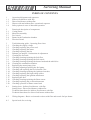
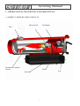
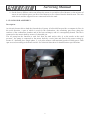
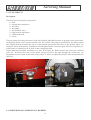
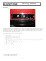
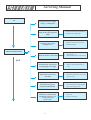
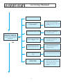
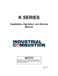
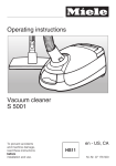
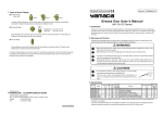
Servicing Manual
Date
09.06.2004
Revision Nr
00
Item Nr
MOBILE (OIL- OR KEROSENE-FIRED) EMERGENCY AIR HEATERS
MIRAGE - TORNADO
SIAL S.p.A
C.so Inghilterra, 15 - 12084 MONDOVI’ (CN)
Tel. 0174 560611 fax. 0174 481086
Website www.sialspa.it
e-mail: [email protected]
Copyright
No section of this document can be reproduced in any form or processed by means of electronic systems, copied or distributed
without written permission by SIAL S.p.A. The translation into other languages is also allowed only under written permission
by SIAL S.p.A. The use of this document is restricted to SIAL servicing centers and to distributors of SIAL products. This
manual is not intended for end users.
Technical changes
SIAL S.p.A. has the right to modify any instruction, description and specification contained in this document without prior
notice.
1
Servicing Manual
FOREWORD
Thank you for choosing the SIAL MIRAGE-TORNADO heaters. We would like to remind you that, as
for any machine, you can get good operation and performance only if the heaters are correctly used and
always kept in perfect efficiency. If required, the SIAL Technical Service can give you suggestions and
assistance.
The SIAL MIRAGE-TORNADO heaters are especially intended for the professional heating of civil,
industrial and agricultural premises.
Read and follow carefully the instructions contained in this manual before starting any
servicing or maintenance operation.
SIAL S.p.A. will not accept any responsibility for damages to persons, goods, properties or to the
machine itself that may result from non-compliance with the instructions contained in this manual and
with the Laws and safety rules in force in the Country of destination.
2
Servicing Manual
INDEX OF CONTENTS
1
1.1
1.2
1.3
1.4
Operational diagrams and sequences
Indirect-fired heaters with flue
Direct-fired heaters without flue
Heaters with and without flue: operational sequence
Safety options in case of abnormal operation
2
2.1
2.2
2.3
2.4
2.5
Functional description of components
Casing/Frame
Motor/fan assembly
Fuel circuit
Burner head/Combustion chamber
Electrical board
3
3.1
3.2
3.3
3.4
3.5
3.6
3.7
3.8
3.9
3.10
3.11
3.12
3.13
3.14
3.15
3.16
3.17
3.18
3.19
3.20
Troubleshooting guide - Operating flow-chart
Checking the supply voltage
Checking/replacing the power cord
Checking/replacing the motor
Checking/replacing the fan
Exhaust gas analysis. Combustion air adjustment
Cleaning the fuel tank
Checking/cleaning/replacing the fuel filter
Checking/cleaning/replacing the fuel nozzle
Checking/cleaning/replacing the burner head and the whirl disc..
Cleaning the combustion chamber
Replacing the motor/pump joint
Checking/adjusting/replacing the fuel pump
Checking and replacing the fuel solenoid valve
Checking/cleaning/replacing the ignition electrodes
Checking/replacing the high voltage cables
Checking/replacing the ignition transformer
Replacing the fuse
Checking/cleaning/replacing the flame sensor
Checking/replacing the overheat thermostat
Checking operation of flame control unit
4.1
Setting chart - Indirect-fired heaters with flue
Setting chart - Direct-fired heaters without flue
Technical data sheets for indirect-fired heaters with flue
Technical data sheets for direct-fired heaters without flue
4.2
Wiring diagrams - Basic version and versions with filter and nozzle fuel pre-heater
4.3
Special tools for servicing
3
Servicing Manual
1. OPERATIONAL DIAGRAMS AND SEQUENCES
1.1 INDIRECT-FIRED HEATERS WITH FLUE
Flue
Burner head
Fuel pump
Combustion chamber
(closed)
Motor
Fuel tank
4
Fan
Servicing Manual
1.2 DIRECT-FIRED HEATERS WITHOUT FLUE
Burner head
Fuel pump
Combustion chamber
(open)
Motor
Fuel tank
5
Fan
Servicing Manual
1.3 HEATERS WITH AND WITHOUT FLUE: OPERATIONAL SEQUENCE
T1
T2
T3
T4
T5
SW
M
T
SV
PH
F
Prepurge time
Ignition time
Operation time
Safety time at flame failure
Aftercooling time
Switch
Motor
Ignition transformer
Fuel solenoid valve
Flame sensor
Flame
Prepurge sequence
During the prepurge time (about 10 s) the fan blows air into the combustion chamber to expell any
residual exhaust gases. The ignition transformer T produces a spark so that any small fuel residuals
coming from the solenoid valve through the nozzle are completely burnt. At the same time the flame
control unit checks for presence of flame or spurious light inside the combustion chamber: should this
occur, the ignition sequence is interrupted and the heater locks out, that is all the electrical components
are immediately unpowered.
Ignition sequence
During the ignition time, after the prepurge time, the fuel solenoid valve EV opens and the spark
produced by the electrode ignites the fuel mist sprayed by the nozzle. The flame sensor (photoresistor)
PH must feel the presence of flame within 1 s (safety time), otherwise the flame control unit locks out and
the motor is stopped. If the flame sensor only feels a small flash and not a continuous flame, the whole
prepurge and ignition sequence is repeated and then, if ignition is still unsuccessful, the unit goes to lockout and stops.
6
Servicing Manual
Operational sequence
15 s after a regular flame ignition, the flame control unit de-energizes the ignition transformer and the
electrodes stop sparking. The heater goes on operating with self-sustained combustion. The flame control
unit monitors the regular presence of flame by means of the flame sensor. Any abnormal condition, such
as lack of fuel, blockage of air inlet/outlet, dirty or clogged nozzle, that impairs regular combustion has
the effect to close the fuel solenoid valve SV and to interrupt the fuel flow to the burner within the safety
time. The flame control unit will then start a new complete prepurge/ignition sequence, and, should the
problem repeat, the unit will lock out and the aftercooling sequence will start.
Restart sequence
If the flame shuts down for any reason, the flame control unit repeats the whole start sequence, consisting
of the prepurge and the ignition sequences. If there is no flame signal within the safety time T4, the
control unit goes to lock-out and the red lamp on the control panel lights up. If, on the contrary, a small
flame signal is detected within the safety time, the control unit repeats the start sequence. The whole
sequence will be repeated 3 times maximum and then the unit will definitely lock out. A maximum
number of 3 ignition tries has been fixed to avoid that excessive smoke is produced during the repeated
starting sequences. This effect could occur when the fuel tank is almost empty and the suction hose
contains fuel and air mixed, or when the nozzle is partially blocked or damaged, and therefore the
pressurized fuel is incorrectly sprayed.
Aftercooling sequence
During this time the heater is subjected to a cooling cycle to avoid excessive overheating of materials
and components that could occur if the motor/fan suddenly stopped. This sequence is also very important
from the point of view of efficiency, as all the residual heat that accumulates in the combustion chamber
can be recovered and sent in the space to be heated.
For safety reasons, it has been established that the high voltage ignition transformer must be energized
during the aftercooling time. By doing this, any small fuel residuals coming from the solenoid valve SV
will burn completely and will not accumulate inside the combustion chamber. Any explosion risk or
abnormal heat release during future ignition sequences is therefore prevented.
The aftercooling time is factory set and independent of the action of a limit control or similar devices on
the combustion chamber. The aftercooling time lasts about 1 minute and 45 seconds.
Lock-out sequence
In the event of flame shut down due to lack of fuel or to another reason (see also the par. “SAFETY
OPTIONS IN CASE OF ABNORMAL OPERATION”) the flame control unit will put the heater in a
safety condition starting the lock-out sequence. During this sequence the fuel solenoid valve SV is
immediately closed within the safety time T4 (< 1s) and then an aftercooling cycle will start to cool the
surfaces of the combustion chamber. The ignition transformer is powered, and therefore a spark is
produced by the electrodes, during the aftercooling cycle as described above.
Reset sequence
The unit can be reset by pushing the red reset pushbutton with integral warning lamp on the control panel.
For safety reasons, reset will only be possible after about 30 s from lock-out. Also in the event of
electrical supply failure/restoration, reset will only be possible after 30 s approximately.
7
Servicing Manual
1.4. SAFETY OPTIONS IN CASE OF ABNORMAL OPERATION
• Spurious (external) light or anticipated ignition
During the prepurge time no flame signal must come to the flame control unit. A flame signal with no
flame could be due to external lights, short-circuit in the flame sensor or in the flame sensor leads, fault in
the flame signal amplifier, fire on board of the unit, or, should the solenoid valve SV not properly
interrupt the fuel flow to the nozzle, to anticipated ignition of the fuel/air mist during the prepurge time.
In this case after the prepurge time and the safety time, the unit goes to lock-out.
Special attention is required in the event that the heater is directly exposed to sunlight (e.g. when used
outdoors). It may happen that sunrays come into the combustion chamber and give a false flame signal,
especially when the heater is new and the inner surfaces are bright and reflect light.
• Flame failure at ignition
If there is no flame signal at the end of the safety time T4, the flame control unit goes to lock-out
condition.
• Flame failure during operation
If the flame signal fails during operation, the flame control unit closes the fuel solenoid valve, the fuel
flow to the nozzle is interrupted and a new prepurge/ignition cycle is started. In case of lock-out, the unit
can be manually reset after 30 s approx.
• Overheat thermostat activation
In the event of combustion chamber overheating, the overhat thermostat interrupts the electrical supply to
the flame control unit and to all components. The heater is immediately stopped.
The possible causes of overheating are described in par. 3 “TROUBLESHOOTING GUIDE”
2. FUNCTIONAL DESCRIPTION OF COMPONENTS
2.1 CASING/FRAME
Description
The heater casing consists of :
a tank made of galvanized steel which also acts as a support for the whole machine.
a support fixed on the tank to which the lower half-shell of the heater is connected. This support
also contains the electrical board.
a lower half-shell which, together with the upper half-shell, forms the air duct where heat is
transferred to the flowing air. All main components are directly fixed onto the lower shell.
an upper half-shell that completes the air duct and can be disassembled by unscrewing 6 screws
for servicing and maintenance. On the indirect-fired heaters with flue the upper shell includes a
circular hole for the flue collar.
on the upper shell you can also find an inspection door that allows operators to reach the
components inside the heater and to carry out most of the repair and maintenance operations.
on the rear, a protection guard is fitted on the air inlet to prevent any contact with the rotating
parts of fan/motor.
on the front, a half cylindrical protection shield if fitted between the combustion chamber and the
lower shell, to limit the temperature of such part, that is directly accessible and can be touched by
the operators.
8
Servicing Manual
On the front a diffuser outlet cone allows the warm air (on indirect-fired heaters) or the mixture of
warm air and exhaust gases (on direct fired heaters) to be released into the heated room. The axle
with wheels and the support foot are connected below the tank.
2.2 FAN/MOTOR ASSEMBLY
Description
An electrical motor drives both the fan and the oil pump. A helicoidal fan provides a constant air flow in
the axial direction, a part of which is used for the combustion ; the remaining part flows along the
surfaces of the combustion chamber and of the heat exchanger, and it is consequently heated. The fan is
connected to the motor shaft by means of a threaded pin.
The oil pump has the function to suck fuel from the tank and to drive it to the nozzle at the rated
pressure : the pump is connected to the motor shaft by a resin joint and fixed to the motor casing by
means of 3 threaded pins. Single-phase, 2- or 4-poles motors with rotational speeds of 2800 rpm or 1400
rpm are used according to the heater model. See technical data sheet for detailed motor specifications.
ILL. 1: particolare gruppo motore MIRAGE 85H – TORNADO 115
9
Servicing Manual
2.3 FUEL CIRCUIT
Description
The fuel circuit is basically composed of :
tank
suction and return hoses
fuel filter,
fuel pump,
fuel solenoid valve,
high pressure microhose
combustion head
nozzle
The gear pump, driven by the motor, sucks fuel from the tank and increases its pressure to the rated value.
At the pump outlet a fuel cut-out solenoid valve SV is fitted. The pump is controlled by the flame control
unit. During normal operation the valve is open and the pressurized fuel flows to the nozzle, where it is
atomized, mixed with primary combustion air and ignited by the electrode spark. The flow of primary air
to the burner is adjusted by an air lock on the combustion head.
Under abnormal operating conditions (see also flow-chart) the flame control unit closes the solenoid
valve SV, fuel does not come to the nozzle but goes back to the tank through the return hose. An
adjustment screw is fitted on the front of the pump ; it allows to adjust the pressure and consequently the
fuel flow.
ILL. 2: particolare gruppo filtro gasolio
ILL. 3: particolare pompa gasolio
2.4 BURNER HEAD/COMBUSTION CHAMBER
10
Servicing Manual
Description
ILL. 4: particolare testa di combustione
A certain amount of air coming from the fan flows around the combustion head, and, depending on the
air lock setting, a part of it - the so-called primary air - flows inside the burner head. The primary air is
distributed and mixed with the atomized fuel jet exiting the nozzle by means of a baffle disc. To get good
combustion and therefore high efficiency, the adjustment of the primary air/fuel ratio must be very
accurate. For this purpose, please carefully follow the setting specifications and instructions contained in
this manual.
The burner head includes :
nozzle holder
air lock
baffle disc (whirl disc)
fuel nozzle
ignition electrode
flame sensor (photoresistor)
The fuel coming out of the nozzle is atomized and mixed with primary air. Additional circumferential
openings on the burner head allow another amount of air, called secondary air, to flow into the chamber.
That is an additional air delivery that completes combustion.
During the whole ignition sequence the electrodes are powered by the high voltage transformer and
produce a spark that ignites the fuel-air mixture.
The function of the whirl disc is to induce a rotational component in the primary air flow and therefore to
decelerate it : this way the mixing of fuel and air is increased and the combustion improved.
The combustion chamber is made of stainless steel. It includes :
a rear end on which the combustion head is fitted
a front end with hole on direct heaters, without hole on indirect heaters
a front flame shield on direct heaters
the heat exchanger with gas passageways
the exhaust gas flue collar
the protection shield around the chamber
a manually resettable overheat thermostat
2.5 ELECTRICAL BOARD
11
Servicing Manual
Description
ILL. 5: particolare cruscotto
The electrical board has the function to broadcast the electrical supply coming from the electrical system
through the power cord to all components, by means of a control/command electronic device, called
burner (flame) control unit. This part has also the task to monitor flame and to ensure safe operation of
the heater during all its operational sequences.
The electrical board consists of the following parts :
Control panel
Protecting cover (against water/dust)
Power cable with strain relief and plug
ON/OFF switch
Remote room thermostat socket with plastic cover and inner electrical bridge (closing circuit for
operation without thermostat)
Reset pushbutton with built-in warning lamp
high voltage ignition transformer
fuse with fuseholder
electronic burner (flame) control unit
3. TROUBLESHOOTING
12
Servicing Manual
SWITCH
ON
Check for correct voltage
rating ( see data plate)
Check that the green warning
lamp on the control panel is
alight
Check fuse (burn-outs,
damages, etc.)
• Check all electrical connections
• Check the warning lamp
•
Replace with a new one with
identical ratings
THE HEATER STARTS
no
•
•
See chapter 3...
Replace the burner control unit
•
Wait 30 seconds and push to
reset
•
Open the inspection cover and
push to reset
Check that the remote
thermostat is properly
connected and adjusted
•
•
Check connections
Set a temperature value higher
than room temperature
For operation without remote
thermostat, check that the
thermostat socket cover is
correctly inserted
in the socket
•
Check the metal bridge inside
the cover
Reinsert and lock
Check the burner control unit
yes
Check that the red lock-out
warning light is not alight
Check that the overheat
thermostat has not been
activated
13
•
Servicing Manual
Check that the oil tank is full
•
•
Tighten the oil line fittings
Check for damages/cracks in the
oil hoses
Check that the nozzle is clean
•
See chapter “Cleaning the
combustion head”
Check that the whirl disc is
clean
•
See chapter “Cleaning the
combustion head”
•
•
Clean the flame sensor with a
soft cloth and ethylic alcohol
Replace the flame sensor if
damaged or burnt
Check the adjustment of air
lock
•
See technical data sheets section
Check for presence of external
(spurious) lights
(sunlight, lamps)
•
Look for - and eliminate - light
reflections due to sunrays,
lamps etc. that could reach and
disturb the flame sensor
Look for fires inside the
machine
Check for air bubbles
in the oil filter
THE HEATER STARTS, THE
PREPURGE SEQUENCE
STARTS BUT THEN THE
HEATER STOPS WITHOUT
IGNITION
yes
no
Ckeck that the flame sensor is
not damaged, clean and
properly fixed in its seat
•
14
Servicing Manual
Check the nozzle size
THE HEATER STARTS,
FLAME IGNITES BUT
COMBUSTION IS NOT
GOOD
yes
• Look for the correct nozzle size
on the setting chart.
• Replace if necessary
Check the air lock adjustment
•
See setting chart
Check that the nozzle is clean
•
•
See chapter 3.8
Replace the nozzle
Check that the fuel filter is
clean
•
See chapter 3.7
•
See chapter 3.12
no
Check that the pump filter is
clean
Check that there are no air
bubbles in the fuel line
•
•
Tighten fittings
Replace faulty pipes/hoses
Incorrect fuel pressure
•
•
Measure and adjust the pressure
Replace the pump (see chapter
3.12)
•
Empty the tank and refill with
clean fuel of correct type
Fuel is of incorrect type, dirty,
polluted or contains water
15
Servicing Manual
Overheat thermostat
incorrectly activated
•
•
Wrong location of overheat
thermostat (after incorrect
servicing, repairs etc.)
Wrong thermostat setting (use of
an incorrect type)
THE HEATER SUDDENLY
STOPS
yes
S
no
Excessive overheating of
combustion chamber
(overheat thermostat
correctly activated)
•
•
•
•
OK
•
•
•
16
Wrong (too large) nozzle size
(see specification chart)
Wrong (too high) fuel pressure
(see specification chart)
Insufficient ventilation due to
motor fault
Insufficient ventilation due to
fan failure
Blockage of airways due to dirt
or foreign objects
Exhaust pipe partially
obstructed
Combustion chamber clogged
by soot. (see chapter.3.10)
Servicing Manual
THE
MAINTENANCE
OPERATIONS
DESCRIBED IN THIS MANUAL MUST BE
CARRIED
OUT
BY
QUALIFIED
PERSONNEL ONLY, IN COMPLIANCE
WITH
THE
ELECTRICAL
SAFETY
STANDARDS IN FORCE.
ONLY
USE
ORIGINAL
OR
RECOMMENDED SPARE PARTS.
3.1 CHECKING THE SUPPLY VOLTAGE
The supply voltage must match with the rated
voltage indicated on the data plate. The actual
input voltage must be within -15% and + 10% of
the rated voltage for good and safe operation.
• Measure the mains voltage, inserting the
multimeter tips into the electrical socket and
compare it with the rated voltage written on
the data plate.
If no voltage is found :
• Check the electrical system fuse(s) and the
main distribution board.
• Check the electrical socket.
Ill. 6
• Unscrew the fixing screw of the resin board
cover and remove the cover.
Note : Only carry out maintenance/repairs on the
heater and not on the electrical system, for which
servicing by authorized personnel is required.
3.2 CHECKING AND REPLACING THE
POWER CORD
.
• Check that the green warning lamp lights up.
If it does not, this means the heater is not
powered.
• Check the conditions of cable and plug and
look for damages and failures.
• Unscrew the fixing screws of the control panel
and extract the electrical board.
Ill. 7
• Check voltage between mains terminals (live
and neutral) on the cable strain relief. If no
voltage is found, check the fuse. If it is
damaged or burnt, replace it with one with
same current ratings (“slow-blow” type)
Ill. 8
17
Servicing Manual
To replace the power cord
• Only use H07RN-F power cords (Europe) or
SJT power cords (USA) with watersplashproof plug.
• Disconnect the line leads and earth leads from
terminals
Ill. 10
•
•
•
•
Check the capacitor.
To replace the motor:
Unpower the machine by unplugging it.
Disconnect the motor leads on the burner
control unit (see picture #10).
• Remove the upper shell by unscrewing its 6
fixing screws.
Ill. 9
• Remove the defective cable.
• Insert the replacement cable into the strain
relief (inner lenght : about 5 cm).
• Fix the strain relief into its seat.
• Connect the line and earth leads to terminals.
• Check for proper operation.
• Reassemble the electrical panel.
3.3 CHECKING AND REPLACING THE
MOTOR
• Extract the electrical board (see picture)
• Check voltage at the motor terminals using a
multimeter.
Ill. 11
• Disassemble the fan. (see chapter 3.4)
• Loosen the fuel pump fixing screws and
disconnect the pump (see chapter 3.12).
• Unscrew the fixing screws of the motor
bracket on the lower support.
18
Servicing Manual
Viti fissaggio
motore
Ill. 12
Ill. 14
• Unscrew the fixing screws of the motor on the
bracket.
• Replace the capacitor with one with same
capacity (µF rating).
• Connect, check operation and reassemble.
3.4 CHECKING AND REPLACING THE
FAN
WARNING : MAKE SURE THAT THE
HEATER IS NOT POWERED BEFORE
OPERATING
ON
MOVING
PARTS
WITHOUT GUARDS IN PLACE. BODY
INJURY DANGER!
• Remove the rear guard and look for possible
damages or obstructions not allowing the fan
to rotate.
To replace a damaged fan:
• Unscrew the fixing screw on the fan hub.
Ill. 13
• Replace motor and fix it on the bracket.
Connect bracket to lower support. Connect
motor leads on the terminal board following
the wiring diagram.
• Check operation.
• Reassemble fan, fuel pump, rear guard, upper
shell and electrical board.
To replace the capacitor :
• Remove the inspection cover.
• Extract the capacitor from its support.
• Disconnect leads on the capacitor.
Ill. 15
19
Servicing Manual
• Insert the pump end into the flue extension.
• Extract the damaged fan and replace it.
• Check by hand that the fan can rotate freely
without interference.
• Check operation after reassembling guards.
3.5 EXHAUST GAS ANALYSIS (for heater
with flue only). COMBUSTION AIR
ADJUSTMENT
Perform an exhaust gas analysis with the ShellBacharach method to check the quality of
combustion.
• Use a standard smokemeter (Shell-Bacharach
pump) .
Ill. 18
• With the heater operating in normal
conditions, draw in the exhaust gases for 10
times
(IMPORTANT :
10
TIMES
EXACTLY), taking care to carry out all
movements slowly and using the complete
piston stroke.
• Extract the paper strip, check the colour and
compare it with the reference scale to assign a
smoke number.
Ill. 16
• Insert a test strip into the pump slot .
Ill. 19
Oil-fired heaters are factory set by the
manufacturer to give a smoke number equal to 0
(zero) of the Shell-Bacharach scale. A smoke
number greater than 1 indicates bad combustion.
Should this occur, the causes of the problem
should be detected and eliminated.
Ill. 17
• Connect an extension for exhaust gas analysis
to the flue adapter.
20
Servicing Manual
The most important factors that can cause high
smoke numbers are :
Clogged combustion chamber due to
incorrect installation (exhaust flue
obstructed or badly designed, see chapter
3.10 and user instruction manual)
Operation without flue adapter
Dirty combustion head, fuel lines and/or
nozzle (see chapter 3.9)
“Too closed” adjustment of air lock (see
chapter 3.9.
Ill. 21
3.6 CLEANING THE FUEL TANK
To clean the fuel tank:
• Lift the heater at about 1 m height using a fork
truck or other suitable means.
• Place a proper container under the heater tank.
• Unscrew the drainage cap on the tank bottom
to discharge the fuel completely.
Ill. 20
Lack of combustion air due to installation
too close to a wall or in a small room
without openings towards outside.
AIR LOCK ADJUSTMENT
• Remove the inspection cover.
• Unscrew the fin screw on the combustion
head.
• Move the air lock in the axial direction to
reach the position shown on the setting chart
supplied by the manufacturer (see setting chart
at the end of this manual)
Ill. 22
To clean the fuel filler filter, extract the filter
from the tank filler cap, clean it and reassemble.
21
Servicing Manual
• Clean the filter cartridge using a soft brush and
then blow compressed air.
To replace the complete filter:
• Loosen the filter fittings and unscrew the
filter/bracket fixing nut .
• Reassemble and connect fuel hoses.
3.8 CHECKING/CLEANING/ REPLACING THE
OIL FILTER
• Remove the inspection panel.
• Remove the fixing screw on the burner head
(nozzle-holder)
Ill. 23
3.7 CHECKING/CLEANING/REPLACING
THE OIL FILTER
Ill. 26
Ill. 24
• Unscrew the lower filter body (glass).
• Pour out the fuel contained in the filter.
• Open the filter and extract the filter cartridge.
• Extract the nozzle holder by rotating it
clockwise to release it from the fixing hooks.
Ill. 25
Ill. 27
22
Servicing Manual
• Remove the inspection cover.
• Loosen (do not unscrew completely) the fixing
screws of the end disc on the combustion head.
Ill. 28
• Unscrew the nozzle taking care not to touch
the electrode, as impacts could damage the
electrode ceramic insulators and impair good
ignition.
Ill. 30
• Slightly rotate the combustion head clockwise
so that the screw heads match with the big
holes on end disc. This will be helpful when
reassembling, as the screws will act as
supporting and centering means for the
combustion head.
Ill. 29
• Clean the nozzle blowing compressed air
inside it.
• If cleaning is not sufficient, replace the nozzle.
Only use the nozzle sizes and types
recommended by the manufacturer (see setting
chart).
• Reassemble the nozzle.
• Reassemble the burner head and the inspection
cover.
Ill. 31
• Extract the combustion head.
3.9 CHECKING/CLEANING/REPLACING
THE BURNER HEAD AND THE WHIRL
DISC.
23
Servicing Manual
Ill. 32
Ill. 34
• Clean the whirl disc using a brush and then
blow compressed air on it. To get good
combustion the air flow openings in the whirl
disc should be perfectly clean and free.
• Extract the combustion chamber and if
required clean using Diesel oil
• Eliminate any Diesel residuals, carefully dry
and reassemble the combustion head, the
burner head and the upper shell.
3.11 REPLACING
JOINT
THE
MOTOR/PUMP
• Loosen (do not unscrew completely) the 3
fixing screws on the fuel pump
Ill. 33
3.10 CLEANING
CHAMBER
THE
COMBUSTION
• Remove the upper shell.
• Disassemble the burner head (see chapter
3.8).
• Disassemble the combustion head (see chapter
3.9).
• Unscrew the fixing screws on the combustion
head.
Ill. 35
• Extract the pump sliding it in the axial
direction.
24
Servicing Manual
• Close the inspection panel and start a short
ignition cycle (10 s prepurge followed by 3 s
first ignition)
• Shut down the heater turning the ON/OFF
switch to 0 so that the aftercooling cycle starts
and the motor continues to rotate.
• Open the inspection cover and turn the screw
on the pump head clock- ot anticlockwise
(reading at the same time the pressure gauge)
until the correct pressure setting is reached.
Ill. 36
• Check the conditions of the coupling and
replace it if required.
• Make sure that the motor shaft can rotate
freely (move the fan by hand to check)
• Reassemble.
3.12 CHECKING/CLEANING/ADJUSTING
/REPLACING THE FUEL PUMP
Ill. 38
• Remove the inspection cover.
To measure the delivery pressure:
• Unscrew the screw on the upper part of the
pump
To measure the suction vacuum:
• Unscrew the screw marked with “V”.
• Connect a vacuum-meter to the port “V”.
To clean the pump filter:
• Unscrew the filter fixing screw on the pump
carter and extract the filter.
Ill. 37
• Connect a pressure gauge with a suitable
measuring range.
Ill. 39
25
Servicing Manual
Ill. 41
• Clean the filter with compressed air or wash it
with clean Diesel oil.
• Reassemble
• Extract the inner cylinder and clean it with
Diesel oil.
To replace the pump:
• Loosen the pump fixing screws.
• Make sure that the motor/pump resin joint is
correctly fitted.
• Replace the pump and reassemble the whole
unit
3.13 CHECKING AND REPLACING THE
FUEL SOLENOID VALVE
• Unscrew the solenoid valve fixing nut.
Ill. 42
Check that the inner cylinder can slide freely. If
required clean the piston.
To replace the solenoid valve:
• Open the electrical board.
• Check voltage at the solenoid valve terminals.
Ill. 40
• Extract the valve casing.
• Unscrew the fixing nut of the inner cylinder.
Ill. 43
If a voltage can be measured on the terminals
shown in the picture but the solenoid valve does
not work :
• Disconnect the valve leads from the burner
control unit.
• Replace the solenoid valve.
• Reconnect and check operation.
26
Servicing Manual
• Disconnect the solenoid fuel valve from
mains.
• Give power to the heater and allow a start
cycle to take place turning the ON/OFF switch
to I (ON).
• Visually check that the ignition electrodes
produce a regular spark .
Warning
At ignition, an 11 kW high voltage is produced
between the electrode tips. Carefully follow the
electrical safety regulations during all servicing
and maintenance operations.
• Reconnect the solenoid valve leads after
checking spark.
3.14 CHECKING/CLEANING/ADJUSTING/
REPLACING ELECTRODES
• Extract the burner head.
To replace the electrodes:
• Disconnect the high voltage leads from
electrodes.
• Unscrew the electrode fixing screws.
Ill. 44
• Check that the electrode tips are clean.
• If not, clean them with a soft brush and then
with compressed air.
• Check the clearances between electrode tips
and between electrode tips and nozzle.
• Adjust the clearances according to the diagram
below :
Ill. 45
• Replace the electrodes and reconnect the high
voltage leads.
• Reassemble the burner head.
3.15 CHECKING AND REPLACING HIGH
VOLTAGE CABLES
• Check that the high voltage cables are properly
connected.
• Check the conditions of high voltage cables
and look for possible damages.
Disconnect the high voltage cables from
electrodes and from the ignition transformer in
the electrical board.
To check that ignition spark is regular:
• Insert the nozzle holder into the burner head
and fix it wih a proper screw.
• Completely open the air lock.
27
Servicing Manual
3.17 REPLACING THE FUSE
• Open the electrical board.
• Extract the fuse from the fuse holder in the
electrical board.
Ill. 46
• Connect the new cables and check operation.
3.16
CHECKING/REPLACING
IGNITION TRANSFORMER
THE
Ill. 48
To replace the transformer:
• Unscrew the transformer fixing screw and nut
on the electrical board.
• Disconnect the high voltage cables from the
transformer.
• Disconnect the high voltage cables from the
burner control unit.
HT transformer
line
• Check the conditions of fuse.
• Replace the faulty fuse with one with identical
current ratings. See technical specifications.
3.18 CHECKING, CLEANING
REPLACING THE FLAME SENSOR
HT transformer
neutral
AND
• Extract the flame sensor from its seat in the
burner head disc, by turning it about ¼ turn to
loosen the fixing feet of flame sensor support.
Ill. 47
• Replace the transformer, reconnect cables to
transformer and burner control unit following
the wiring diagram shown on the label placed
on the electrical board cover.
Ill. 49
28
Servicing Manual
• Replace the faulty sensor.
• Reconnect, reassmble and check operation.
• Gently push the sensor leads to extract the
flame sensor. Clean the sensor glass with a
cloth soaked with ethylic alcohol to eliminate
any soot or dust residuals.
3.19
CHECKING/REPLACING
OVERHEAT THERMOSTAT
THE
• Remove the inspection cover and/or the upper
shell.
• Check that the thermostat is properly fixed and
connected.
To replace the thermostat:
• Disconnect the thermostat cables.
• Replace the thermostat.
• Reconnect and reassemble.
To reset the overheat thermostat:
• Unplug the heater
• Remove the inspection door
• Push the reset button
Ill. 50
It is possible to check the proper operation of the
flame sensor simply using a multimeter.
Connect the multimeter terminals to the sensor
leads and proceed as follows:
• Set the multimeter to measure resistance
• Expose the flame sensor to light.
• Under normal conditions, the tester should
show ohmic resistance quickly decreasing as
illumination increases.
To replace the flame sensor:
• Disconnect the flame sensor leads from the
burner control unit (see wiring diagram ).
Ill. 52
3.20
CHECKING OPERATION
BURNER (FLAME) CONTROL UNIT
OF
Perform the following tests to check operation of
the burner control unit.
Check reset pushbutton/ lock-out warning lamp
Ensure that the lock-out warning lamp is
correctly connected (see diagram)
Ill. 51
29
Servicing Manual
M1
M2
M19
Ill. 53
Check that there is electrical continuity
between the terminals 1 and 3 of the reset
pushbutton.
Check that there is a 18-20V voltage
between the terminals M2 and M19 of the
burner control unit when the unit is in
lock out condition (the lamp is alight).
Check voltage on the transformer, motor
and solenoid valve terminals and that they
are correctly energized according to the
operational cycle.
Electrical continuity check
Unplug the heater
Turn switch to I (ON)
Set the room thermostat in a operating
(closed) position
Check that the overheat thermostat is
closed
Check electrical continuity between
terminals M3 and M4 of the electronic
control unit (with all wires connected).
Ill. 54
Power supply to loads
Plug the heater.
Turn switch to I (ON)
Set the room thermostat in a operating
(closed) position
Using a multimeter, check that the burner
control unit is powered
The voltage supply to components must match
with the mains voltage.
Should this not occur, or should the components
not be correctly energized according to the
operational cycle, replace the flame control unit
with a new one.
Lock-out test
Start the heater and wait that the ignition cycle is
completed. (wait until the ignition spark stops).
Disconnect the flame sensor fast-on from
terminal M5 on the burner control unit.
The heater must immediately lock-out.
The red warning lamp must light up.
30
Servicing Manual
Reset must be possible only after at least
30 seconds.
31
Servicing Manual
4.1
SETTING CHART - INDIRECT-FIRED HEATERS (WITH FLUE)
CHAMBER
INLET
FAN
MIRAGE
37 H
USA
# 8 holes
6 mm dia.
dia.=350mm
3 blades
18°
MIRAGE
55 H
USA
# 8 holes
6 mm dia.
MIRAGE
85 H
USA
# 8 holes
10 mm dia.
WHIRL
(BAFFLE)
DISC
FUEL
PUMP
FUEL
PRESSURE
BURNER
NOZZLE
AIR LOCK
OPENING
OVERHEAT
THERMOSTAT
out. dia.=76mm DANFOSS
in. dia.=27mm
R3
10 blades
12 bar
DANFOSS
0.65 60°H
3 mm
170 °C
lock position
1
(red markings)
dia.=350mm
3 blades
18°
out. dia.=76mm DANFOSS
in. dia.=27mm
R3
10 blades
12 bar
7 mm
170 °C
lock position
2
(red markings)
dia.=500mm
4 blades
33°
out. dia.=76mm DANFOSS
in. dia.=22mm
R5
10 blades
12 bar
14 mm
170 °C
lock position
3.5 - 4
(red markings)
32
DANFOSS
1.00 60°H
DELAVAN
1.50 80°W
Servicing Manual
SETTING CHART - DIRECT-FIRED HEATERS (WITHOUT FLUE)
CHAMBER
INLET
FAN
WHIRL
(BAFFLE) DISC
FUEL
PUMP
FUEL
PRESSURE
BURNER
NOZZLE
AIR LOCK
OPENING
OVERHEAT
THERMOSTAT
TORNADO
67
USA
# 8 holes
dia. 6 mm
dia.=350mm
3 blades
18°
out. dia.=76mm
in. dia.=27mm
10 blades
DANFOSS
R3
12 bar
DANFOSS
1.25 60°H
4 mm
100 °C
lock position
1.5
(black markings)
TORNADO
115
# 8 holes
dia. 10 mm
dia.=500mm
4 blades
33°
out. dia.=76mm
in. dia.=27mm
10 blades
DANFOSS
R5
13 mm
100 °C
lock position
3.5
(black markings)
33
12 bar
DELAVAN
2.25 80°W
Servicing Manual
TECHNICAL DATA SHEET FOR INDIRECT FIRED OIL HEATERS – 37 kW MODEL
Thermal Specifications
Airflow Specifications
Maximum Thermal Power (Diesel Oil)
Consumption
Kg/hr at 3°C (37F)
U.S. gal/hr
Efficiency
%
Power Input
kcal/hr
kW
BTU/hr
Power Output
kcal/h
kW
BTU/hr
Fuel Pressure
12 bar
Smoke Index
Air Lock Adjustment
mm
Maximum Thermal Power (Kerosene)
Consumption
Efficiency
Power Input
Power Output
Fuel Pressure
psi
Air Lock Adjustment
mm
Kg/hr
%
kcal/hr
kW
BTU/hr
kcal/hr
kW
BTU/hr
2,88
0,90
87,10
31304
36,40
125216
27266
31,70
109063
Air Flow Rating
m³/h
2000 m³/h
Fan Diameter
mm
Blade #
Pitch
350 mm
14 in
3 sickle-shaped
18°
1180 ft³/min
Rated Voltage
V/Hz
110/60
Rated Current
A
7,0
Rated Power
W
460
Motor Power
W
430
Temperature Rise (Delta)
at 20°C (68 F)
175 psi Noise Level
dB(A) average
with original hood
1,00
Nozzle Type
3,0 Manufacturer
Type
Flow Rate
2,64
87,10 Air Ducting
29106 Hose Diameter
33,84
116425 Maximum Hose Lenght
25352
29,48
101406
12,00
Electrical Specifications
54°C
at 1 m
77
GPH
97 F
at 2 m
75
DANFOSS
60° H
0,65
315 mm
12 in
8m
25 ft
*oil gross heating value Kcal/kg
34
10869,44
*kerosene gross heating value Kcal/kg
11.025,08
3,00 according to standard prEN 13842:2002
Rotational Speed
rpm
Fuse
A
Size Specifications
Weight
70 kg
154 lb
Lenght
1188 mm 47 in
Width
620 mm
24 in
Height
790 mm
31 in
3400
15 slow-blow
Tank Capacity
51 liters
14 U.S. gal
Outlet Diameter
308 mm
12 in
Flue Diameter
150 mm
6 in
Package Specifications
1250 mm Height
Lenght
530 mm Weight
Width
830 mm
72 Kg
Servicing Manual
TECHNICAL DATA SHEET FOR INDIRECT FIRED OIL HEATERS – 55 kW MODEL
Thermal Specifications
Airflow Specifications
Maximum Thermal Power (Diesel Oil)
Consumption
Kg/hr at 3°C (37F)
U.S. gal/hr
Efficiency
%
Power Input
kcal/hr
kW
BTU/hr
Power Output
kcal/h
kW
BTU/hr
Fuel Pressure
12 bar
Smoke Index
Air Lock Adjustment
mm
Maximum Thermal Power (Kerosene)
Consumption
Efficiency
Power Input
Power Output
Fuel Pressure
psi
Air Lock Adjustment
mm
Kg/hr
%
kcal/hr
kW
BTU/hr
kcal/hr
kW
BTU/hr
4,16
1,29
87,10
45217
52,58
180868
39384
45,80
157536
Air Flow Rating
m³/h
Fan
mm
Blade #
Pitch
2500 m³/h
1475 ft³/min
350 mm
14 in
3 sickle-shaped
18°
Rated Voltage
V/Hz
110/60
Rated Current
A
7,0
Rated Power
W
460
Motor Power
W
430
Temperature Rise (Delta)
at 20°C (68 F)
175 psi Noise Level
dB(A) average
with original hood
1,00
Nozzle Type
4,0 Manufacturer
Type
Flow Rate
3,81
87,10 Air Ducting
42006 Hose Diameter
48,84
168022 Maximum Hose Lenght
36587
42,54
146347
12,00
Electrical Specifications
73°C
131 F
at 1 m
75
at 2 m
73
GPH
DANFOSS
60° H
1,00
315 mm
12 in
8m
25 ft
*oil gross heating value Kcal/kg
10869,44
*kerosene gross heating value
35 Kcal/kg
11.025,08
7,00 according to standard prEN 13842:2002
Rotational Speed
rpm
Fuse
A
Size Specifications
Weight
76 kg
167 lb
Lenght
1405 mm 55 in
Width
620 mm
24 in
Height
790 mm
31 in
3400
15 slow-blow
Tank Capacity
51 liters
14 U.S. gal
Outlet Diameter
308 mm
12 in
Flue Diameter
150 mm
6 in
Package Specifications
1470 mm Height
Lenght
530 mm Weight
Width
830 mm
80 Kg
Servicing Manual
TECHNICAL DATA SHEET FOR INDIRECT FIRED OIL HEATERS – 85 kW MODEL
Thermal Specifications
Airflow Specifications
Maximum Thermal Power (Diesel Oil)
Consumption
Kg/hr at 3°C (37F)
U.S. gal/hr
Efficiency
%
Power Input
kcal/hr
kW
BTU/hr
Power Output
kcal/hr
kW
BTU/hr
Fuel Pressure
12 bar
Smoke Index
Air Lock Adjustment
mm
Maximum Thermal Power (Kerosene)
Consumption
Efficiency
Power Input
Power Output
Fuel Pressure
psi
Air Lock Adjustment
mm
Kg/hr
%
kcal/hr
kW
BTU/hr
kcal/hr
kW
BTU/hr
6,64
2,06
88,50
72173
83,92
288692
63873
74,27
255493
Air Flow Rating
m³/h
Fan
Diameter
Blade #
Pitch
4500 m³/h
2650 ft³/min
500 mm
20 in
3 sickle-shaped
28°
Rated Voltage
V/Hz
110/60
Rated Current
A
12,0
Rated Power
W
800
Motor Power
W
750
Temperature Rise (Delta)
at 20°C (68 F)
175 psi Noise Level
dB(A) average
with original hood
1,00
Nozzle Type
14,0 Manufacturer
Type
Flow Rate
4,86
88,50 Air Ducting
53582 Hose Diameter
62,30
214328 Maximum Hose Lenght
47420
55,14
189680
12,00
Electrical Specifications
72°C
130 F
at 1 m
73
at 2 m
71
GPH
DELAVAN
80° W
1,50
450 mm
18 in
16 m
52 ft
*oil gross heating value Kcal/kg
10869,44
*kerosene gross heating value
36 Kcal/kg
11.025,08
14,00 according to standard prEN 13842:2002
Rotational Speed
rpm
Fuse
A
Size Specifications
Weight
121 kg
267 lb
Lenght
1680 mm 66 in
Width
690 mm
27 in
Height
938 mm
37 in
1700
20 slow-blow
Tank Capacity
100 liters
26 U.S. gal
Outlet Diameter
443 mm
17 in
Flue Diameter
150 mm
6 in
Package Specifications
1760 mm Height
Lenght
650 mm Weight
Width
965 mm
124 Kg
Servicing Manual
TECHNICAL DATA SHEET FOR DIRECT FIRED OIL HEATERS – 67 kW MODEL
Thermal Specifications
Airflow Specifications
Maximum Thermal Power (Diesel Oil)
Air Flow Rating
Consumption
Kg/hr at 3°C (37F)
5,22
2800m³/h
U.S. gal/hr
1,62
Efficiency
%
Fan
Power Input
kcal/hr
56739 Diameter
350 mm
kW
65,98 Blade #
3 sickle-shaped
18°
BTU/hr
226954 Pitch
Power Output
kcal/hr
kW
Temperature Rise (Delta)
BTU/hr
at 20°C (68 F)
Fuel Pressure
12 bar 175 psi Noise Level
at 1 m
dB(A) average
75
Smoke Index
1,00
Air Lock Adjustment
Nozzle Type
mm
4,0 Manufacturer
Type
Maximum Thermal Power (Kerosene)
Flow Rate
GPH
Consumption
Kg/hr
Efficiency
%
Air Ducting
Power Input
kcal/hr
0,00 Hose Diameter
kW
0,00
BTU/hr
0,00 Maximum Hose Lenght
Power Output
kcal/hr
0,00
kW
0,00
BTU/hr
0,00
Fuel Pressure
psi
0,00 *oil gross heating value Kcal/kg
Air Lock Adjustment
*kerosene gross heating value Kcal/kg
37
mm
0,00 according to standard prEN 13842:2002
Electrical Specifications
1650 ft³/min
Rated Voltage
V/Hz
110/60
14 in
Rated Current
A
6,0
Rated Power
W
460
Motor Power
W
430
at 2 m
73
Rotational Speed
rpm
Fuse
DELAVAN
A
60° S
1,25
Size Specifications
Weight
65 kg
143 lb
Lenght
1405 mm 55 in
Width
620 mm
24 in
Height
750 mm
30 in
10869,44
11.025,08
3400
10 slow-blow
Tank Capacity
51 liters
14 U.S. gal
Outlet Diameter
308 mm
12 in
Flue Diameter
Package Specifications
1470 mm Height
Lenght
530 mm Weight
Width
830 mm
76 kg
Servicing Manual
TECHNICAL DATA SHEET FOR INDIRECT FIRED OIL HEATERS – 115 kW MODEL
Thermal Specifications
Airflow Specifications
Maximum Thermal Power (Diesel Oil)
Consumption
Kg/hr at 3°C (37F)
9,12
U.S. gal/hr
2,83
Efficiency
%
Power Input
kcal/hr
99129
kW
115,27
BTU/hr
396517
Power Output
kcal/h
0
kW
0,00
BTU/hr
0
Fuel Pressure
12 bar 175 psi
Air Flow Rating
m³/h
4800 m³/h
Fan
mm
Blade #
Pitch
500 mm
14 in
3 sickle-shaped
28°
Electrical Specifications
2850 ft³/min
Rated Voltage
V/Hz
110/60
Rated Current
A
12,0
Rated Power
W
800
Motor Power
W
750
Temperature Rise (Delta)
at 20°C (68 F)
Noise Level
dB(A) average
at 1 m
75
at 2 m
73
Smoke Index
Rotational Speed
rpm
1760
1,00
Air Lock Adjustment
mm
Maximum Thermal Power (Kerosene)
Consumption
Kg/hr
Efficiency
%
Power Input
kcal/hr
kW
BTU/hr
Power Output
kcal/hr
kW
BTU/hr
Fuel Pressure
psi
Air Lock Adjustment
mm
Nozzle Type
13,0 Manufacturer
Type
Flow Rate
GPH
DANFOSS
80° W
2,25
Air Ducting
0,00 Hose Diameter
0,00
0,00 Maximum Hose Lenght
0,00
0,00
0,00
0,00
*oil gross heating value Kcal/kg
10869,44
*kerosene gross heating value 38
Kcal/kg
11.025,08
0,00 according to standard prEN 13842:2002
Fuse
A
Size Specifications
Weight
101 kg
222 lb
Lenght
1680 mm 66 in
Width
690 mm
25 in
Height
898 mm
35 in
20 slow-blow
Tank Capacity
100 liters
14 U.S. gal
Outlet Diameter
308 mm
12 in
Flue Diameter
150 mm
6 in
Package Specifications
1760 mm Height
Lenght
650 mm Weight
Width
965 mm
116 Kg
Servicing Manual
4.2 WIRING DIAGRAM
Basic version
39
EV
Fuel solenoid valve
TR
High voltage transformer
M
Motor
SL
Warning lamp
TS
Overheat thermostat
FS
Fuse
FC
Flame sensor
PL
Reset pushbutton
IN
Switch
TH
Remote (room) thermostat
FR
Heated filter (optional)
Servicing Manual
Version with heated filter and nozzle pre-heater
40
EV
Fuel solenoid valve
TR
High voltage transformer
M
Motor
SL
Warning lamp
TS
Overheat thermostat
FS
Fuse
FC
Flame sensor
PL
Reset pushbutton
IN
Switch
TH
Remote (room) thermostat
FR
Heated filter (optional)
Servicing Manual
4.3 SPECIAL SERVICING TOOLS
1.
2.
3.
4.
5.
Smokemeter
Strips for smokemeter
Shell-Bacharach reference scale
Pressure gauge for oil pressure measurement
Electrical multimeter
5
3
2
4
1
Ill. 55
Ill. 56
41