1
OPERATING INSTRUCTIONS
& SERVICE MANUAL
STEREO RECEIVER
SANSUI SEVEN
SANSUl ELECTRIC CO., LTD.
Not For Sale
Congrat ulations on Jommg the thousa nds of proud, satisfied owners
of quality stereo components from Sansui, Japan's foremost audio only spec ialist.
In man y ways, the SEVEN is a culmination of our long expe rience
and ard uous resea rch in the design and manufacture of qualit y audioonly eq uipment.
It s tuner section combines an FET-eq uipped super sens itive FM
frontend and an IC -eq uipped FM IF amp li fi er which ensures outsta nd ing FM se lec tivit y and superb tone quality .
Its am plifier sec tion is a 160-watt masterpiece des igned , tested and
proven to bring out every subt le shade of the or iginal sound, regardless of the prog ram source, free from distortion.
Ove r-all , the receive r is eq uipped with practicall y all the swit ches,
con trols, inputs and outputs that you would ever need to enjoy today's
most advanced hi-fi sound reproduction.
This manual has been prepared to guide you in ope rating and caring
for the rece iver correc tly , so that you will get the most out of its
built-in high performance and exce ptional ve rsa tilit y. May we sug gest that you read it once carefully?
CONTENTS
SWITCHES AND CONTROLS ........... .... .... ......... .. ..... .... 3,4,5
CONN ECTIONS .... .. .. ....... .. .... ......... .. ........... .. ... ....... .. 6,7,8
OPERATIONS .. ... ...................... ........ ..... ......... .... ... .... ...... 9
4-C HANNEL STEREO SYSTEM ...... ... . __ ... ... _.. .. .. .. .... . .. ..... 10
NOISE REDUCTION SYSTEM ............... ................. _.. .. ..... 11
S IMPLE MAINTENANCE HINTS ...... .. .......... ....... .. ........ . 12
SIMPLE MA INTENANCE HINTS/ ACCESSOR IES .... ..... .. . 13,14
GENERAL TROUB LESHOOTING CHART .... ... .... ....... ... 15, 16
SPECIFICATIONS ............. ............. .. ..... .. ............. ......... 17
DISASSEMBLY PROCED URE ..... ... ...... ........ ..... .... .. ....... .. 18
TEST POINTS .. ...... ... ........... ................... ... .. ...... ......... .. 19
SCHEMATIC DIAGRAM OF AMPLIFIER SECTION . .... . 20, 21
SCHEMATIC DI AGRAM OF TUNER SECTION .... ...... .. ... 22,23
ALIGNMENT .... .. ... .. .. .. .. ....... ..... .... _.. ..... ............. 24,25,26
PRINTED CIRCUIT BOARDS AND PARTS LIST ............ 27- 39
OTHER PARTS AND THEIR LOCATION ON CHASSIS ... 40- 42
Not For Sale
Not For Sale
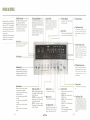
SWITCHES AND CONTROLS
Explained Oil the ri ght are the functions of the
\'ariolls switches and controls located on the front
panel of you r SEYE:\. They are all designed
and located to gi\'e you maximum control of the
rccei\'er with the greatest ease. Read the instruc·
tions oncc and you'll find C\'cry onc of them is
very e<:lsy to operate.
The Operating Instructions Sheet. accompanying
this booklet. carrics thc same infonl'lation in a
condensed form. for future quick references.
Noise Filter Switches
Tuning and Signal Meters
Loudness Switch
LOW: Push to cut off low- frequency noise such
as the rumbling of the turntahle motor.
HIGH: Push to cut off high-frequency noise such
as the scratch noise of a worn record, tape hiss
or the whislc noise in radio broadcasts.
Lea,·e the switches off at all other times.
The desired F1\[ station is pinpointed when the
Signal i\lctcr pointer has s wung as far to the
righ t as possible and the Tuning ~[eter pointer is
perfectly centered.
:\11 ,-\:\1 station, in con trast, is correctly tUlled in
when the Signal i\lcter pointer has swung as far
10 the r ight as it will go. You need not pay
attention to the Tuning ~lcter.
The human car is slich that an apparent 'drop-out'
of the lows and highs occurs when you're lislening at a low \'oIulllc Ic"cl. Pushing this switch
compensates for this apparent loss and appropn ately accents the lows and highs.
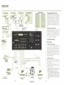
, - - - - FM Stereo Indicator
I.ights when the rccci,"cr is tuned to an
tion broadcasting in stereo.
Function Indicators
F~ 1
sta-
Tape Monitor Switches
These switches control t:1pe monitor circuits
and :!. See p. Y of Operating Instructions for
detailed instructions on the ope ration of tnpc
decks.
,--- Mono Switch
Push to hear in mono whate\'cr program source
you may h;I\'c tlcljus ted the recei\'cr to reproduce.
Power Switch
Push once to turn on the power supply for the
entire recci\·er. once marc to turn off.
4.Channel Adaptor Switch
If YOll.connect " ·I·channel adaptor to the SE\·Ei\
3nd Illal,: e other necessary conncct ions. you will
be able to upgradc this :'! ·('ilan1lc l s terco receive r
to ·i-channel ste reo capahilities hy pus hing this
switch (rerer to p. 10 of ()I>crating Instructions).
(hhc.rw ise . he s ure to ).; cep it orr.
Power Indicator
FM Muting Release Switch
HeadphoneJack ---------------------------4.~~~
Accommodates a stereo headphone set for monitor ing and private listening, \ Vhen listening with
headphones, turn the Speaker Selector to' O FF.'
The headphones used should be a dynamic type.
,
Speaker Selector - - - - - - - - - - = - - - - - - - - - - - - - - '
OFF: To cut off the sound from the speaker
Triple Tone Controls
systems when listening with headphones.
A: To dri\'e the speaker systems connected to
the SYSTEi\[ A terminals.
B: To drive the ones connected to the SYSTE~l
13 terminals.
C: To dri,·e the ones connected to the SYSTE\[
C terminals.
A+B: To dri,·e both A and 13 pairs of speaker
systems.
A + C: To drive both A and C pairs of speaker
systems.
-
3
This switch. if not depressed. climinates thc interstation noise cOIll111only heard whe n tuning on the
1'\1 hand. I t s hould be pushed to release the
Illuting function whe ll you arc try ing to tUlle in
a weak F~I station.
"
.'---- -
Tuning Control
Volume Control _ _ _.oJ
_---J
B ASS: Usc to strengthen or weaken the receiver's
low-end response. Turn it clockwise to emphasize
the lows hy :ldR pe r s tep.
MIDRANGE: l ise to strengt hen or weakcn the
midrange response. Turn it clockwisc to emphasize the mid ranges by Id13 per step.
TREBLE: 1i.e to stren)( then or weaken thc
high-end response. Tllrn it clockwise tocmphasize
the highs by :ldR per step.
Tllrn it clockwise to raise the volume.
Balance Control
1'S(' to halalH'c thc lert and right channels.
N.R. Adaptor Switch _----J
If you connect a noise reduction adaptor to the
SEVEN and want to record or reproducc on a
tape deck \·ia such ad3ptor. push this switch.
-
4
Not For Sale
Tunc in thc dcsired st<ltioll hy turning this rontrol.
' - - - - - Selector Control
Depending on what you wish to hear. turn to the
appropriate position .
PHONO. 2: Selects a turntahle connected to
the PI [ONO ~ inputs.
PHONO.l: Selects the one connc(·ted to the
PIIONO 1 in puts.
FM AUTO: To hear 1' \1 hroadcasts, whcther
s tereo or mono.
AM : To hear .-\1\1 broadcasts.
AUX: To hear whatc\'cr progrm source IS connected to the At IX inputs.
Tape Monitor.2 Jacks
1\ part of tape monitor circuit 2, these jack s connect a tape deck with phone plugs. The upper
jack is for recording, and the lower one for playback. Connecting: a tapc deck here automatically
disables the pin jack terminals and DIN connector
socket of tape monilor circuit :l on the receivcr's
rear panel.
-
5 -
CONNECTIONS
SPEAKER SYSTEM·A
LEFT SPEAKER
RIGHT SPEAKER
OUTDOOR FM ANTENNA
Connecting Speaker Systems
The SEVEN connects up to three p<lirs of spe<lker
systems. Any pair may be driven independently
or a combination of two pairs may be dri\'cn . as
selected by the Speaker Selector. Connect them to
the recei\'er as instructed in the diagram on the
left. taking care not to confuse the left and right
channels and the plus and minus leads. Also. be
ver y cCireflll not to s hort-circuit the pills nnd minus
leads,
JOO n BALANC[o
r[[D£R CA8LE
CONNECT NOISE
REDUCTI ON ADAPTOR
HERE (SEE p , 11 )
INDOOR 'T' SHAPED FM ANTENNA
CONN ECT 4,CHAN NEL
ADA PTOR HERE
(SEE p, 10)
About the Speaker Impedance
Each speaker system connected to ),our SE\,El\
must possess an impcdfll1cC of ., to 16 ohms. Should
YOLI wish to dri\'c two pairs of speaker systems
simultaneously (hy turn ing: the Speaker Selector to
the ·.\ -'- If 0" '.-\ + C' position). each of them n","'
have an impedance of H ohms or more.
Connecting Antennas
CONNECTI NG TO
ANTENNA AND_"'-SP KI! , E F\,M~
FM Antennas
).
T.Shaped Feeder A ntenna
If you li ,'e in the proximity of hroade<lst sl,ltiomi,
quality reception can he tlsually ohtained by ju!"t
selling: lip the T- shaped feeder cahle antcnn;1 supplied with the recei,'cr. Connect thc an tenna to thc
recei"er's F~ I :~oon terminals. set up the receiver
for F~I reception. stretch the antenna to a full T
shape, and adjust it ~ height ami directioll ulltil the
hest rece ption is ohtained,
I
WALL AC OUTLET
Outdoor FM Antenna
Should the feeder cable ,mtenn" described "I>OI'e fail
to give you a dear rec·epl ioll . try installing an outdoor F~I antenn".
\Vhile many different types of antenna are commercially ;w<li lable. it is <ldvisahle to lISC one with
at least 5 or 7 clements.
Using feeder cahle, COT1I1et:t SllC h antenna to the F~I
300n antenna terminals of the receiver. Oilsen'e
the following suggestions when connecting it:
1. As an antenna is directional, locate and orient
the antenna in the place and direction which give
you the hest reception . Actually listen to your
favorite FM station while you make the adjust.
men ts,
TURNTABLE 1
COMPONENTS
I-tt:t--~
RECORD
PLAYBACK
/ ~.
....\
,-
•
OIN CABLE
(~. '.~ )\' . j
~
J
TURNTABLE
'.-
_ _= LEFT CHAN N EL
- - - RI GHT CHANNEL
-
8 -
L-LL
v v Co
FRONT PANEL
TAPE DECK 2
Not For Sale
r._
v v
Co
~_ '
TAPE DECK 1
-
7
-
2. Be Sllre no t to let the anten na tou ch electric
cables and other objects.
3 . Arrange the route of the feeder cable so as to
keep it as short as possible.
4. Try to kee p the antenna as far from streets
as possible to preven t picking up the noise generated by automobiles.
If you should need long feeder cable to connect the
ante nna or where the automobile traffic is hea,-y, it
is ad"isable to employ 750 coaxial cable. In this
case, howe\'er, it is necessary to connect a ma tching
transformer between the antenna and the coaxial
cable to match their impedances. Be su re to connect the cable to the Fi\ 1 750 tennimds. (If the
antenna itself has an impedance of 750_ no matching transformer is needed.)
Connecting Tape Decks
The SEVEN is pro"ided with two tape monitor circuits. One has pin jack terminals, while the other has
pin jack terminals, a DIN connector socket and
phone type jacks. If you arc connecting only one
tape deck, you are absolutely free to usc any lenninals which arc most convenicnt to YOll _ But if you
arc connecting two tape decks, be su re to connect
o ne of them to the first tape monitor circuit. and
the other to any terminals of the second tape
monitor circuit.
If U sing Pin Jacks
If you are usi ng the pin jack terminals to connect
you r tape deck, proceed as follows:
1. Connect a pair of s hielded cables bet ween the
'TAPE 1 (or 2) REG' pin jack terminals of the
SEVEN and the recording input termimtls of you r
tape deck.
2. Connect anot her pair of such cables bet wee n the
recei"er's ' TA PE 1 (or 2) \ION' pin jack terminals
and the tape deck's playback (monitor) output
tenninals _ .
AM Antenna"
Ferrite Bar A ntenna
The highly sensitive AM ferrite har an tenna, pro·
'Aided on th e rear of the recei,-er, is usually sufficicnt to obtain a quality reception of A~I stMions. To
usc, simply pull it out as illustrated_
No te: If you don't connect a 4-channel adaptor to
the 4-CHANNEL ADAPTOR terminals on the rear
panel, you Illel)' connect flnother tapc deck to them_
O utdoor AM A ntenna
Should the bar antenna fail to givc you a clear reception. however, connect a picce of pye wi re supplied to the Ai'vl-A terminal on the recci,-er's rear
panel and ex tend it outside a window or on the
roof. Still beller results can be obtained if you
ground thc recei,-cr.
Use the :!·CI I OUTPUT term inals as recordi ng
outputs, and INP UT te rminals as playback inputs.
If U sing the DIN Socket
In the rather unlikely event that you r tape deck is
equipped only with a DIN connector socket, plug
the DI 1 connector cable extending from it into the
5· pin DIN connector socket (marked TAPE-2 RECI
PLA Y) on the receiver's rear panel.
Connecting Turntables
As the SEVEN is equipped with two phono input
circu its, it is possible to employ two turntables or
two tonearms with magnetic cartridges.
Connect the output cables of the turntable to the
PHONO 1 or 2 input terminals. Be sure to keep
the left and right channel cables in proper order.
If Using Phone Jacks
Should your tape deck be equipped with cables with
phone type plugs, you may connect it to the phone
jacks on the receiver's front panel. The tape deck's
recording input plug should be inserted into the
upper 'TAPE REC' jack, and its playback output
plug into the lower 'PLAYBACK' jack.
Con necting a tape deck to the phone type jacks
automatically disables the pin jack terminals and
DIN connector socket of the second tape monitor
circuit.
No te:
1. If you wish to use a moving-coil (MC) ty pe
cartridge, be sure to employ either a step-up transformer or separate head amplifier between the
turntable and the SEVEN.
2. If you wish to use " ceramic or crystal type
cartridge, connect the outputs of the turntable to
the receiver's AUX input terminals.
-
8
Not For Sale
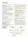
OPERATIONS
FM Reception
3. To mon itor the sou nd being recorded, push the
TAPE MON 1 or 2 Switch, depending on which of
the two tape monitor circuits is ;Iccommoda ling the
tape deck at the moment.
1. Set the Selector Control to 'FM AUTO:
2. Tune in the desired FM station by turning the
Tuning Control.
I t is correctly pinpointed when the Signal Meter
pointer has swung as far to the right as possible and
the Tuning ~Il e ter pointer is accu rately centered.
3. Use the various other controls and switches to
sui t your personal preference.
Note: ~Ionitoring is possible only if the tape deck
is equipped with separate heads for recording and
playback.
To Reproduce a Recorded Tape
1. Push the TAPE MON 1 or 2 Switch, depending
on which of the two tape monitor circuits is accom ·
modating the tape deck at the moment.
2. tart the tape deck in the playback mode.
3. se the nlrioliS controls and switches to suit
your personal preference.
AM Reception
l. Set the Selector Control to 'AM.'
2. Tune in the desired AM station by turning the
Tuning Knob until the Signal Meter pointer sw ings
as far to the right as it will go nea r the frequency
of that station. The Tuning Meter dose not operate
for A~1.
3. Use the ,·arious other controls and switches to
sui t your personal preference.
Recording into Two Tape Decks
Simultaneously
l. Set the Selector Control to the program source
you want to record.
Playing Records
2. Start both tape decks in the record ing mode.
1. Set the Selector Control to 'PHONO·I' or
'PHONO·Z: depending on which inpu t circu it you
are using.
2. Start the turntable and play the record.
3. sc the ,"arious controls and switches to suit
your llersonal preference.
Recording from One Tape Deck into the
Other
1. Push the TAPE ~ION 1 Switch.
2. Start the tape deck connected to the second tape
monitor circui t, in the recording mode.
3. Now start the other tape deck (conneted to the
first tape mon itor circuit) in the 1)layback mode.
Note: The copying (dubbing) of a recorded tape,
as described above, is only possible from a tape
deck connected to the first tape monitor circui t to
the one connected to the second tape monitor cir·
cuit.
Recording and Playback on
Tape Decks
To Record into a Tape Deck
l. Set the recei,·er's Selector Control to the program
source you want to record .
2. Start the talle deck in the recoding mode.
Signal Path Diagram
of Tape Record/
Playback Circuit
--------------------------------------------,
[
__
NOISE R:::OUCTlON....
ADAPTOR
I
r - 4 . CHANNELl
2-CH. ADAPTOR
~---~~[EC--,-,'-N ? 0-1 ,
-------------~~~.."&
.~
-r
r
rm-l
,
0
~AJ'N~ 1
N.R.
ADAPTOR
I
kAJ'N~2
sw.
sw.
1 ThiS program shows
REC
MON
1:J
9 -
-@)-
SW.
@- .____
REC PLAY· REC MOO
L TAPE. ' .J
-
~8~PTOR
SW.
L_~'~~w'~~~~t~~~.______ _~_____
Not For Sale
IINPUT
______ _____ ____
REC PLAY
I BA~TAPE. 2 --·-.J
,
I
j
:
4-CHANNEL STEREO SYSTEM
4.CHANNEL STEREO
Connecting a 4·Channel Adaptor
The sound we daily hear is a mixture of the sounds
that reach Ollf ears straight from the sound source
- be it a rnusical instrument, a jet, a Ill a ll's mOllth
Of what ha\'e you-and the 'indirect sounds' that
Connection of such a rear amplifier or 4-channel
adaptor is easy. Just connect the 4·CHA NEL
ADAPTOR 2·CH . OUTPUT terminals of your
SEVEN with the input terminals 01 such rear ampli·
fier or 4·channel adaptor, then connect its 4·CI-IAN·
:-.IEL ADAPTOR II PUT terminals with the output
terminals of such unit.
ar rive at ollr cnrs only after th ey arc reflected of(
various su rfaces. such as the walls, ceiling and so
forth . Four·channel recordings arc m£ldc using two
microphones in the front of the concert hall and
two in the rear (to simplify the explanation). The
'indirect sounds' with their compl icated wa\'cforms
arc mainly picked up by the two rear rnicrophones
and reprodu ced out of the two r ear speakers in a"",
channel stereo sc t-up for t{rca tl y enhanced 'ambience'
effects. . Th e result is almost as if the oriJ.!inal li\'c
pedorll1 ~mcc were f e-played r ight in YOUf own rool11.
This new approach can now be yours simply by
adding certain equipment-mainly. a ansui-lchannel rear amplifier and a second pair of speaker
syste ms-to your :!-chan ncl stereo system .
Operation
SANSUI 4 ·CHANNEL REAR AMPLIFIER QS·SOO
To operate the rear amplifier or ·1· channel adaptor
so connected, push the 4CII ADAPTOR Switch on
the receiver·s front panel, and otherwise follow its
manufacturer's instructions.
4 · CHANNEL REAR AMP
I--------------~,
I
I
I
I
4· CHANNEl
ADAPTOR
=
,
POWER
AM P.
I::
'
'
'
J
I'- ____ • _ _ _ _ _ _ _ _ _ _ J
2·CH
-
10 -
Not For Sale
1=
~
REAR
SPU![I SISTIM
OUTPUT
PROGRAM
SOURCES
---~
INPUT
SEVEN
:i
NOISE REDUCTION SYSTEM
About Noise Reduction Systems
Tape hiss is the single greatest annoyance to tape
recording: enthusiasts. To eliminate this noise, se\'cr·
al noise reduction systems have been developed to
date.
The latest innovation in this area is ",.lIed the Dolby
system. which reduces tape hiss most effecti"e1y
without affecting the tone quality of the program
source sound. It ilwolvcs compressing low·lc\"cl
signals (where tape hiss is most annoying) during
recording and then expanding them during playback
in exactly the opposite manner.
The Dolby system often more than doubles the
stereo listening enjoyment. T'o take maximum ad·
"anlage of it, you only need couple a commercially
available Dolby :\oise Reduction Adaptor to your
SE\ ·E:\.
Connecting a N.R. Adaptor
Connect the Noise Reduction (N.R.) Adaptor to the
NOISE RED UCTION ADAPTOR jacks on your
EVEN.
W ith this in mind, make these connection. between
the SEVE:\ and the n.r. adaptor:
SE \ 'EN
N.R. Adaptor
OUT ... Input jacks of its recording circuit.
R EC ... Output jacks of its recording circuit.
MON .. . Input jacks of its playback circuit.
IN ..... .Output jacks of its playback circuit.
Operating a N.R. Adaptor
Operate the n.r. adaptor correctly according to the
instructions supplied by its manufacturer. Then it
is simply a maller of operating your tapc deck COf-
rectly for recording and playback and pushing the
·.R. ADAPTOR Switch on the SEVEN's front
panel.
Note: \Yhen you are recording via a two-circu it
type Dolby Noise Reduction Adaptor, changing its
mode switch from record to playback by mistake is
likely to cause a loud oscillating phenomenon. Be
very careful to avoid such mistake.
Such adaptor usually has four pairs of jacks-two
for connecting a tape deck, and two more for connecting an amplifier (in this case the SEVEN).
However, as you r SEVE is equipped with provisions for connecting up to two tape decks, it is
better to connect your tape deck(s) to the SEVEN
(refer to 'Connecting Tape Decks' on page 8).
With you r tape deck(s) so connected, regard the
NOISE REDUCTION ADAPTOR-OUT, -IN,
-REC and ·~ION jacks on you r SEVEN's rear
panel as equivalent to these terminals:
OUT ... Tape recording output jacks of an amplifier.
IN .. .. .. Tape playback input jacks of an amplifier.
REC .. . Recording input jacks of a tape deck.
MON ... Playback output jacks of a tape deck.
-
11-
Not For Sale
SIMPLE MAINTENANCE HINTS
A bout the Place of Installation
PM Connectors
The wooden cabinet of the SEVEN is designed so
that any heat radiated inside will cffecti\'e!y esc.ape
through it. Proper care should therefore be taken
of the dissipation of such heat if you wish to place
somcthin~ on top of the recei,·er or place it inside
a closed box. etc. Abo\'e all. ",'oid placing it where
it may he exposed to the direct sunlight.
These arc the U·shaped jumper connectors connce·
ting the 'PRE
T' (preamplifier output) jacks and
the ':\1A IN IN' (power amplifier input) jacks on the
rccci\'cr's real panel, and can be easily pulled out.
With these connectors unplugged, the preamplifier
and power amplifier sections arc separated and may
be independently uscd. For example, a different
power amplifier may be coupled to the 'PRE OUT'
jacks.
Separating the preamplifier and power amplifier
sections makes it possible to upgrade YOUT stereo
system further by adopting the 'electronic crossover
system: among other things.
a
W hen Connecting a Turntable, etc.
To connect a turntable. tape deck and so forth. it is
strongly recommended to use thick. shielded cables
with minimal distrihuted capacitance and to keep
them as short as possible.
To solder the pin plugs supplied as accessories onto
such shielded cables. refer to the illustration below.
No te :
1. Be sure to le""e the P1-.1 connectors firmly plugged in unless YOll want to separate the preamplifier
and power amplifier sections for some purpose.
2. Turn off the Power Switch without failure
he fore you plug in or Ollt the P ~ l connectors.
H um and H owling
Care must be taken nc\'cr to place a turntable on or
too nCar a speaker system, or the vibration of the
speaker system is transmitted and causes howling.
It is best to keep these components completely
separate but if this is impossible. place a thick
clishion between them .
Ilummillg is a phenomenon caused
by
incomplete
ELECTRONIC
CROSSOVER
DIVIDER
or incorrect lurntablc·recch·cr connections. Should
this occur, check to see if all connections are COIl"!pletely made and if the connecting cables are suffi ciently thick. Be sure to connect the grounding
lead (or terminal) of the turntable to the GND
terminal of the SEVEN. It may suppress the hum
noise wich may otherwise occur.
-
12 -
Not For Sale
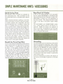
SIMPLE MAINTENANCE HINTS / ACCESSORIES
Quick-Acting Fuses
Rear-Panel AC Outlets
Thc SEVEN's power transistors are protected by
four quick-acting fu ses. They are located on the
rear panel of the rerch·cr. concealed inside a plastics
cover.
Of the two AC outlets provided on thc rcar-panel,
the one marked 'SWITCHED' is con trolled by the
front -panel Power Switch. The othcr, markcd' NSWITCHED: is always 'live' and indcpendent of
the Power Switch. Thc voltage dcli"cred at these
outlets is the same as the power supply voltage
uscd .
Thc . ' \\-ITCHED' ' md ' NSW IT CHED' outlets
h,I\'e a power capaci ty of 50 VA and 150 VA, reo
specti\·ely. Before you connect any appliance to
them, be SUfe that it is adjusted for use at the same
power supply voltagc, and that its power consumption is not beyond these figu res.
\ ¥hen a function Indicator is glowi ng, if no or dis-
tortcd sou nd comes out of onc or both of the speaker systems, examine their connections and your
operating procedure once. If nothing is wrong with
th el11 , it is possible that one or more of the quickacting fuses ha"e hlown. Should this happen, disconncct the power cord from thc wall AC outlet immediately, then remo\"c the metal co\'er by loosening the two screws securing it to the rear panel, and
chcck the four quick-acting fuses. If you find any
of them blown. disco\'cr and eliminate the cause of
the blowout, and replace it with a new 4-ampcrc
quick-acting fuse supplicd. Probablc causes of the
blowout include excessively large input signals and
a short-circui t at the speaker terminals.
Grounding
Should the Power Fuse Blow
Any noise I,;ckcd up by thc connccting cables can be
cffecti"ely groundcd by connccting a piece of PVC
(pol)'\"inyl chloride) or enameled wire to the 'GND'
terminal on the SEVEN's rear panel, attaching a
small copper plate or carbon rod to the other end
and burying it dec I' underground . Thc grounding
Icads of other cquipmcnt in your stereo system may
be connected to the same terminal to ground the
e ntire system at once.
If you hm'e connected an ex ternal A~l antenna to
the recch'c r, it is advisable to grou nd it at the samc
lime.
If no Function Indicator should glow and thc rccei"cr
simply remains dcad C\'cn after you have turned on
its Power Switch, it is possible that its power fu se
has blown. If this happens, disconnect the power
cord from the wall AC outlet at once and examine
the power fusc on the receiver's rear pancl. If you
find it blown, replacc it with a new glass-tubed fuse
of the rated capacity (5-ampere for 100 to 127 volts,
:J-ampere for 220 to 250 ,·ol ts). Nevcr use a fuse of
a different capacity or a piece of wirc, even as a
stop-gap measure, or serious dangcr could result.
/
.)/,/
"/;/ '//);/ ,
//'/'/ "////////1/ / 1///////////,;;
ATI ACH COPPER PLATE OR
CARBON ROD. THEN BURY
DEEP UNDERGROUND
-
13 -
Not For Sale
Voltage Adjustment
In ordcr to perm it the use of your SEYE:\ in any
part of th e world, it is equipped with a \"oit agc
Selcctor. It is set to thc correct power supply
voltage of your area prior to shipment . so there
is no need to tOll ch it. l-IOWC\·c r. should you mo\'c
afte r purchasi ng thc unit and fi nd thc powcr supply
voltage is differe nt. simpl y reset the selector
:1S
follows:
1. Remove th e two screws securing th e name plate
on the unit's rear panel, then
r c n'lO\'C
the name
platc.
nplug the \ 'oltagc SclcelOr once, and rese t it
2.
so that the arrow mark on it faces the correct \'olt age indication. C hange the power fu se also w hen-
C,'cr thc powcr suppl y "oltage has changed. For
100/ 11 7 \"olt opcration, use a 5·am pere g lass·tu bed
fuse . For 220/ 2,10 \"olt operation, use a :l· am perc
on e.
3. Where the power su pply vollage considcra bly
flu ctuates. the Voltage Selector may be reset to
avoid unpleasant side effects of slIch fl uctuat ion .
Resct it to the voltage immediately higher than the
peak of the fl uctuation.
24ntl-
-
22OV- '
_ ._
t
111V _
'-- lUUV
i;
,,
~
About Servicing
ACCESSORIES
If anyth ing should ever go wrong with your
SE\' E ,or if you h3\'c any question about it.
plcase contactthc Sansui dcaler from whom you
purchased it or your nearest Authori zed Sansui
FM Antenna ....................... ... ........ .... .. ..
AM Antenna ......... .. .... ......... ... .. ... .. .. ... .. .
Pin Plugs ...... ......... ................ ... ..... ... ...
Butterfly Bolts ...... ..... .............. ...... .....
Washe rs ...... .... ... .... .. ..... .. .... .. .... ........ .
Polishing Cloth ...... ..............................
Quick·acting Fuses (4A .. .... ... ... ... ..... ... .
8. Operating Instructions and Service
Manual .... ..... ............ ............ .. ..... ... .....
9. Operating Instructions Sh ee t ... ...... ........ .
1.
2.
3.
4.
5.
6.
7.
Ser \'ice Station.
-
14 -
Not For Sale
1
1
2
2
2
1
2
1
1
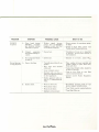
GENERAL TROUBLESHOOTING CHART
If the receiver is otherwise operating satisfactory, the
more common (causes of trouble ma y generally be a ttributed to the following:
1. Incor rec t conn ections or loose terminal cont~tc l s . Check
the speakers. turntable. tape deck. antenna and power
cord.
2. Improper operati on . Before operating any audio com-
ponent, be sure to read its manufacture's instructions.
3 . Improper location of audio components. The proper
positioning of compon ents, such as speakers and turntable,
is essential to maximum stereo enjoyment.
4. Defective audio components.
The following arc some other common causes of mal·
function and what to do about th em .
PROGRAM
SYMPTOM
PROBABLE CAUSE
WHAT TO DO
AM. FM or
MPX reception.
A . Constant or intermit·
le nt noise heard at
times or in certain
area.
• Discharge or oscillation
caused bv e lec trical appli·
ances, such as fluorescent
lamp. TV set. D.C . motor
rectifier or oscillator.
.. Attach noise limiter to elec trical appliance producing noise. or attach it
to receiver's power souce.
• Install outdoor antenna and ground
receiver to raise SN ratio.
.. Rcverse power cord plug/receptacle
connections.
.. If noi se occurs at certain frequency,
attach wave trap to input.
.. Keep receiver at proper distance from
other electrical appliances.
• Natural phenomena, such as
atomosphcric. static or thuo ·
derbolts .
• Insufficient antenna input
due to ferroconcrete wall or
long dis Hmce rrom stat ion .
A~\'I
reception .
A . Noise heard at par·
ticular time of day.
in cert ain area or
o\'cr part of dial.
• Peculiar to AM broadcasts.
• Install antenna for maximum antenna efficiency. Sec CONNECTIONS
in operating instructions booklet.
.. In some cases, noi se can be elimi·
nated by grounding receiver or reo
versi ng power cord plug/receptacle
conn ec tions .
B.
• Adjacent·channe l interference or beat interference.
• Such noise cannot be co mpletely
e liminated by receiver. but it is
advisable to turn Treble control
countcrclockwise, or turn on High
Filter.
.. Keep TV set at proper distance from
stereo system .
High·frequ ency noise.
• TV set too close to stereo
system .
FM reception .
A . Noisy .
I
. too
Poor nose limiter err eel or
low SN ratio due to in·
sufficient antenna input.
ote: FM reception is affected con ~i derably by
transmission condit ions of station. such as power
and antenna efficiency . As a result, you may
receive onc s tation quite we ll while recei \'ing
another station poorly.
.. Install antenna (supplied ) ror maxi·
mum signal strength .
• If this does not prove effective. use
exclus i\'e FM outdoor antenna . If
using TV antenna for both TV and
FM with divider. make sure TV
reception is not affected.
.. Excessive ly long lead· in wire of an·
tenna ma y cause noise.
B. A series of pops.
• Ignition noise caused by
starting of nearbv auto mobile engine.
.. Install antenna and its lead-i n wire
at proper distance rrom street or in crease ant enn;, input as described
before .
C. Tuning noise between
stations.
.. Results from nature of FM
reception .
.. FM Muting Release switch
depressed .
.. Release FM Muting Release switch.
-115-
Not For Sale
• Ditto .
PROGRAM
F~I · MI'X
SYMPTOM
A. Noise
heard during
reception
but inaudibl e during
F~ I mono reception .
F~'I · ~IPX
reception .
B.
Channel
separation
deteriorates during re-
PROBABLE CAUSE
I
*' \"eaker
'" Oricnt antenna fo r maximum anten na input.
• Switch on Il igh Filter and or turn
Treble control cou nterclockwise.
• Excess heat.
• Circulation of room ai r is importa nt
to receiver. Be sure that receiver is
will ventilated.
" In terft:'rencc .
• Indica tor is not fauily. adjust VR. o:.
• Turntable p);'tced directly on
spea ker .
• Place cushi on bctwct! n turntable and
spea ker cabi net or place them away
from each other.
'" Conn ecti ng shielded cables should be
as short as possible.
• Turn on Low F ilter or tu rn Bass
control cou nt erclock wise.
• Consult nearest Radio Regu lator y
Bureau.
signal
because
service area of F~I · ~IPX
broadcast is onl\" half that
of F~I mono bro'adcasl.
ception .
C. Stereo indica tor blinks
on and off.
Record playing A.
or tape playback .
Il um or howling .
WHAT TO DO
• \ Virc ot her than shielded
cable used .
• Loose tcr rn imd contHCt.
• Shielded cable too close to
power cord. Huorcsccntlamp
or other appliances.
• Nearb\' amateur radio sta·
tion
TV transmission antenna .
or
B. Surface noise.
• \Vorn or old record .
• \Vorn phono stylus.
• Phono stylus dusty.
" Imploper stylus pressure.
-
16 -
Not For Sale
'" Recondition playback head of tape
deck or replace turnwble stylus.
'" Turn Treble control counterclockwise
• Turn Hi gh Filter on.
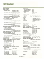
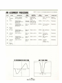
SPECIFICATIONS
AUDIO SECTION
POWER OUTPUT
IHF MUSIC POWER :
OUTPUT LEVEL:
TEPE MONITOR (DIN):
PHONE TYPE, PIN:
PREAMPLIFIER:
160W 4n 01 I.000H.
120W an 01 I ,OOOH.
CON TINUOUS RMS POWER (each channel driven)
60/60W 4n 01 I ,OOOH.
47/ 47W an 01 I.000H.
CONT INUOUS RMS POWER (both channl s driven)
41 T 41W
an
of
MAX :
30mV
I SOm V
SOOm V
4.000mV
( 01
0.5 %
dist or tion)
TONE CONTROLS
BASS:
MIDANGE:
TREBLE :
FILTERS
LOW:
HIGH :
LOUDNESS:
1.000Hz
CON TINUOUS RMS ROWER (both channels driven,
20 t o 20 ,000Hz):
36 + 36W an load
TOTAL HARMONIC DISTORTION
POWER AMPLIFIER ONLY :
less than 0.3 % a t ra ted output
+ ISdS, -
ISdS 01 20H. (3dS Slep)
+ SdS , - SdS 01 IS,OOH. (IdS Slep)
+ ISdS, - ISdS 01 20,OOOH.(3dS Slep)
- IOdS 01 SOH. (12dS/ ocl.)
- I OdS 01 10,OOOH. (12dS/oCl.)
T IOdS at 50Hz. + adB a t
10,OOOH.
PRE-AMP ONLY (PHONO to Pre output):
less thon 0 .2 % at rat ed outpu t
PRE-AMP ONLY (AU X to Pre output):
less than 0.1 % 0 1 rat ed ou tput
OVE R-ALL (AUX to Power out put):
TUNER SECTION
FM :
TUNING RANGE :
SS 10 10aMH.
SENSITIVITY (IHF):
I.SI'V
SIGNAL TO NOISE RATIO: be ller Ihan 63dS
IMAGE FREQUENCY REJECTION :
less thon 0 .3 % r ated out put
IN TER MODULATION DISTORTION (70Hz: 7 ,0 00Hz=
4: 1 SMPTE METHOD)
POWER AMPLIFIER ONLY :
be rter thon SOdS at 98MHz
leu thon 0.3 % or rat ed output
SPURIOUS RESPONSE REJECTION:
OVER -ALL (AUX to Power output):
be n e r tha n lOOdS
less than 0.3 % at rot e d out put
be tter thon 60dB
SELECTIVIT'I':
IF REJECTION :
be ller Ihan IOOdS
CAPTURE RATIO:
beller Ihan I.5dS
SPURIOUS RADIATION :
less Ihan 34dS
TOTAL HARMONIC DISTORTION
POWER BANDWIDTH (IHF): 10 10 SO,OOOH. 01 an load
FREQUENCY RESPONSE: 01 I wall
OVER-ALL (AUX to Power output):
15 10 40,OOOH. + IdS, - I.SdS
POWER AMPLIFIER ONLY:
15 10 40,OOOH. + I db, - 1.0dS
DEVIATION FROM RIAA: + IdS, - I dS (30 10 IS,OOOH.)
LOAD IMPEDANCE:
410 16n
DAMPING FACTOR :
appro,imalely 50 01 an load
CHANNEL SEPARATION (at rated output 1,000Hz)
POWER AMPLIF IER ON LY: 60dS
OVER-ALL (from PHONO): SOdS
OVER -ALL (IHF)
SOd S
HUM AND NOISE (IHF)
OVER-ALL (from PHONO): 70dS
OVER-ALL (from AUX):
SOdS
POWER AMPLIF IER ONLY : 90dS
INPUT SENSITIVITY AND IMPEDANCE (at rated
output 1,000Hz)
PHONO:
2.Sm V (SOk!1)
MAX. INPUT CAPACITY:
MONO: less than 0.3 %
STEREO: less Ihan 0.5 %
STEREO SEPARATION :
beller Ihan 40dS 01 400H.
FREQUENCY RESPONSE : 30 10 12,OOOH. + IdS , - 2dS
ANTENNA INPUT IMPEDANCE :
300n ba la nce d. 75n unba lance d
AM :
TUNING RANGE :
535 10 1,60SkH.
SENSITIVITY (Bar Antenna ): 46dS/m
SELECTIVITY (± 10kHz): beller Ihan 30dS
IMAGE FREQUENCY REJECTION :
be tl er than 100dB/ m a t l , OOOk Hz
IF REJECTION :
SEMICONDUCTORS:
74 Transis tors, 42 Diodes, .4 Zener Diodes . 1
Ie
POWER REQUIREMENTS
POWER VOLTAGE:
I CO, 11 7, 220, 240V SO/60H.
POWER CONSUMPTION : Ma,. JIOVA 2 S0W
Raled I JOVA 102W
DIMENSIONS:
440mm, 17·J/S' W .
140mm,S.9/ 16' H.
J2Smm, 13' 0.
14.3kg (JI.S lb•. )
WEIGHT:
lOOmV at 0.5% di sto rtion
AU X:
I SOm V (SOk!1)
TAPE MONITOR :
I SOmV (SOk!1)
N.R . ADAPTOR:
ISOmV (SOk n )
4 ·CH ADAPTOR:
ISOmV (SOk!1)
POWER AM PLIFIER INPUT: SOOmV (SOk!1)
-
be tt er tha n l 00dSjm at l ,OOOkHz
17 -
Not For Sale
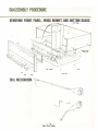
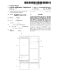
DIASSEMBLY PROCEDURE
REMOVING FRONT PANEL, WOOD BONNET AND BOTTOM BOARD
,.wooo
IOfaT
...
10"011 !'\All
DIAL MECHANISM
""'--
'~ ._........,
-
......
~~
, j1
I
. -.r... .
-
18 -
Not For Sale
/
~~
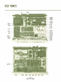
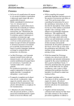
TEST POINTS
-----
- ----
L1 0' ----1-1--:
T P , 0 ' ---!-l~.JJ'.
-
19 -
Not For Sale
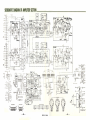
SCHEMATIC DIAGRAM OF AMPLIFIER SECTION _ _ _ _ _ _ _ _ _ _ _ _ _ _ __
A." .... 01<1
$._'.,..
,_..
•,., "" '" _ _ olio«' ..,..,
s.,TO<l'
5G>.'
-20-
Not For Sale
-
2.-
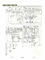
- SCHEMATIC DIAGRAM OF TUNER SECTION _ _ _ _ _ _ _ _ _ _ _ _ _ _ __
Til .. ,
2 SC e 3 0(Cj
stu cro/( S,:.. ,, '
I.
1.
!'
I:
Z.
I.
c,¥
lD' fiUCII!%, ,s,,.'1
~'; AJ/O
AIIll
z.
'~~
1.
~.~
1.
~
($lo.s..,$..... ... · J
WI
c.'1
Hfti'!lR ~ (:;' •.'I. •• s.•.<.,,')
<l~
f.::H ~I;JfI.u...~·1
r.
L
s.....s,; .s,.J
0,"
~MlrrJII l
!Soo.~)
lQ/1
or.
~ lIttu;r,J.v ~r.!..
~
elF
DK.
HI6JI FlIJVI
PH<lIfJ:
"..,,'" I
ofF
.,
i!tJlfr')
k
~lf
1f'UJ<£!JS (S... . ~l
I. on
~ ~
..
~
,;
•• ,
~ :~', s... .s..:)
f.v-~~.~~s.::f
"7.U SOl
(5 .. )
I'/>l II,I1IHO CS-I
I.
L
P.' I
. ,
HD/;Q
-22-
Not For Sale
-23-
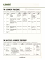
ALIGNMENT
OUTPUT BALANCE ALIGNMENT
OF POWER AMPLIFIER
CURRENT ALIGNMENT OF
POWER AMPLIFIER
STEP I
STEP I
1.
CONNECT/ ADJUST
REMARKS
1.
Conn cc. 8·oh m (or 16·ohm)
CONNECT/ ADJUST
Remove F .. , and F.., .
REMARKS
Refer.o " Abou.
.hc Quick·Acting
Fuses" (p"ge I3).
resistor (minimum rating of
50 walls) .o SYSTEM ·A le h ·
channe l speaker terminal.
2.
2.
Connect \'oltmeter to s"lmc
speaker terminal.
with 0 . 1· 1V
'0SYS·
3.
Sc. Speaker Scle.or
TEM·A posi.ion.
4.
Adjus. VR... (I. h channel) so
that voltage will be kept
within O± 5OmV .
5.
For right
c h ~lnn cl .
range.
(right
3.
Tun on recei\'er.
4.
Connec t
(tester)
Be sure power is
where F bO l was (refer to illustration below) ,
ammeter
turned on be fore
connecti ng ammeter . Set ammeter to its 30......
IOOmA range.
repeat
above procedure. but adjust
VR MI ,
Turn VR,., (lch and right
channds) full y count erclockwise.
Use voltmeter
channel)
5.
in
Turn VR...
(Ief. channel)
slowl y cloc kwise until
st ep 4 .
ammeter shows 15± 3mA .
6.
Turn orf power. then replace
Fso , .·
7.
Turn on power again .
8.
Now , connect ammeter where
F lO: was (re rer to illustra -
tion below) .
9.
Turn VR,.. (right channel)
slowl y clockwise unt il mume·
ter shows 15 ± 3mA .
10.
Turn off power .• hen replace
F80! .
AMMETE R
TO AMMETER
-
24 -
Not For Sale
(30 - 100mA
Fe0 2
eOI
( RIGHT)
( LEFT)
ALIGNMENT
FM ALIGNMENT PROCEDURE
NOTE: Set Fr..·1 signal generator Ic\'c1 to minimum fi rst
Equipment required : 1. Sweep Gene rator 2. Oscilloscope 3. FM Signa l Genera tor Ii . Multiplex Stereo Gcncrotor 5. AC V .T . V .~I .
STEP
I
ALIGN
I Discr imi·
1
nalor .
I
GENERATOR
I
S weep
generator
1O.7MHz
±200kH ? .
I
FEED
SIGNAL
OUTPUT
INDICATOR
3.
O .S .C .
4
I Repeat 2
FM s ignal generator Same as above .
I08MHz 400Hz 100%
modula tion .
I
ADJUST
ADJUST
FOR
O .S .C. coil
L ,ot ·
Maximum .
Same as above .
I08MII? .
D .S.C. trimmer
Maximum .
Maximum .
Osc illoscope
and V .T .V.M.
at outpu t load.
FM signa l generator
88MHz 400Hz 100%
modulation.
I
88MH? .
To antenna
termi nals .
O .S .C .
SET
S curve.
Oscilloscope
connected to
2F .
2.
DIAL TO
FM
Discrim inator
transformer
T ~Ol primar y
and secondary .
To TP ,O ' via
lOpF ceramic
capacitor.
I
Te lo, .
and3.
5
RF Amp. FM signal genera tor
Circuit.
9OMH ? 400Hz 100%
modu la tion .
Same as above.
Same as above.
9OMHz .
Antenna coi l
Llo" L lo! and
L loa ·
6.
RF Amp. FM signal ge nerator
Circuit .
106MHz 400Hz 100%
modulation .
Same as above.
Same as above.
106MII? .
Trimmer T C IOI , Maximum .
Telo: and T C lo,.
7
Repeat 5
and 6.
I
I
I
FM MULTIPLEX ALIGNMENT PROCEDURE
00 not attem t to a lign Multil>lex Circ uit unless followi ng equipment is II vni lable :
I. r..<lulti plex Stereo Generator 2. Osc ill~ cope 3. AC V .T .V . M. 4. Low Frequenc y Osc illator 5. FM Signnl Generator
STEP
I
ALIGN
1.
f
Separatio n V R.
2.
67 kllz Coil.
3.
Stereo
separati on
19kHz Coi l.
4.
Stereo
separation YR.
I
GENERATOR
Low frequency
osc illator 67 kH z .
FM signal generator
98MH ? 100 % modulation
Stereo signa l generator
- composite si~m' l with
pilot signal. Ie t channel,
40% modulation.
Same as above.
I
FEED
SIGNAL
4A .
Antenna
termina ls
Tune to signal.
I Same as above.
-
215 -
I
OUTPUT INDICATOR
I
ADJUST
I
ADJUST FOR
V R,o"
Fully
counter·
clockwise.
V .T .V.M. and
Osc illoscope at TP,ol'
V.T .V .M. and
osci lloscope at ri ght
channel output load .
L,o, ·
Minimum .
L,a.'
C hannel·R
minimum .
Same as above.
VR,ol'
Same as
above .
Not For Sale
AM ALIGNMENT PROCEDURE
STEP
ALIGN
1.
IF
Transfor-
GENERATOR
455kHz ±3OkHz
NOTE: To al ign . set AM signal generator level to minimum .
FEED
SIGNAL
OUTPUT
INDICATOR
O.S .C .
AM · generator
535kHz 400Hz 30%
Modulation .
3.
O.S .C .
wave form .
Antenna Oscilloscope
terminals . and V.T .V.M .
535kH1. . O .S .C. coil T oo•.
Maximum .
I
Best IF
at output load .
Samt as above.
1600kHz . O.S .C. trimmer
cap. TC,,,.
AM -generator
Same as
Same as above .
600kHz 400Hz 30%
Modulation .
Same as abo\'e.
above .
6OOkllz . RF transformer
T,ol'
Same- as
Same as above .
600kHz .
AM· generator
1400kHz '100Hz 30%
Modulation .
Same as
above .
Same as above .
1·IOOkHz.
Same as above.
Same as
above .
Same as above .
Maximum .
Repeat
2 and 3.
5.
RF amp.
6.
Antenna
circuit .
7.
RF amp.
S.
9.
ADJUST FOR
I.F .T . T .... T ao.
and T MS.
Same as
above .
AM ·generator
1600kHz 400Hz 30%
Modulation .
4.
ADJUST
Oscilloscope
, and V.T .V .M.
at3G.
TP.. , .
Sweep-generator .
mer .
2.
DIAL
SEnlNG
Antenna
circuit.
,
I
I above .
Ferrite bar
I antenna coil
Maximum .
Maximum .
Loo, .
RF
t
trimmer
~·(aximum .
1·IOOkHz. Antenna
circuit
trimmer
TCao, .
Repeat
5,6,7,8.
FM DISCRIMINATOR WAVE FORM
AM IF WAVE FORM
(
\
IOK"' 1
)
...
KH.
-
28 -
Not For Sale
Maximum .
TC.. , .
IO KHI
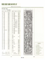
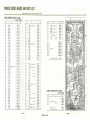
PRINTED CIRCUIT BOARDS AND PARTS LIST
W: Parts No.
X: Purts Nnme
Y: Stock No
Z: Position of Pa rts
...
FM IF BLOCK ( F-1450A)
St o ck No . 7520540
x
w
R20'
no n
R202
IS'!l
R""
R,..
R,.,
3.9,n
' 70 n
390n
R206
Ion
R20'
Rn,
680 n
3.3'n
1.5l n
220 n
lkn
390n
nn
680n
3.3' n
1.5ln
220 n
lkn
390n
680n
330n
Rm
S6n
R223
22 n
nn
R,..
R209
R210
R211
R212
R213
R214
R215
R216
R217
RZ18
R2. 9
R120
Rn .
Rn,
Rn,
lk n
lk n
R' 30
loon
R232
Rm
10ln
680n
10ln
1.5, n
R",
loon
R' 31
R,,,
1.5ln
330n
R2J9
22lil
R240
100l n
680 n
15lfi
R,)J
R:Z41
R.2"2
R244
4.no
'son
R245
820n
R, ..
nn
loon
ISln
R243
R24]
R2.a
R2.9
R,,.
R251
R252
c •.
S.6 l 0
R2V
R,,.
± IO% J{w
C,.,
0100221
0100153
0100392
2C
2C
2C
0100471
010139 1
2C
2C
0100 100
0101681
Ie
2C
010 1332
2C
0100152
0100221
0100102
2C
2C
2C
0 101391
2C
0 101220
0 101681
Ie
28
0101332
28
0100152
28
0101221
0 100102
0 101391
0 101681
28
28
28
28
010 1331
0100560
0101220
28
28
28
0100220
0 100562
0 100102
0100 102
0101 10 1
01 0 1103
0 10 168 1
2A
2A
IA
1A
2A
2A
1, 2 C
0 1011 03
Ie
010 11 52
010 1101
1C
Ie
0 101 152
Ie
IC
TRm
TR203
TR,..
TR?OS
TR206
IC
IC
D=
0100331
0100223
0 101104
1.8kH
27 0n
220n
2. 2<n
w
z
y
010 1681
1. 2 B
0100153
0100472
0100151
0100B2 1
0 10 12 20
0101101
0100 153
0100 182
0100271
0 10022 1
01 00222
I B
Cm
C203
e,..
e?OS
e""
e 20'
C,..
Cm
C 210
e 21 '2
C213
C21.
C21.5
e 216
e 217
e 21!
C 219
Cm
Cn ,
Cm
Cn,
en.
en,
Cn ,
Cm
Cn .
Cm
C'lO
C:lli
Cm
x
0.022/1f
0.022p F
0.0 22p F
0.0 22pF
0.022p F
0.022/JF
0.04 7pF
0.0 22JIF
0.0 22pF
0.04711F
::g%
y
50
v
CC.
220 P F)
220pF ± IO%
10p F
220pF ±IO%
0.0 22p F
:~%
22pf ± IO%
0.022 P F)
:~ %
0.0 22pF
47pF ± 10'6
0.0 22 P
::"
0.022p F
16
50
v
50
50
v CC.
v CC .
50
v
±I O%
50
v CC.
f)
22 pf
0.022 p f
0.022/lf
0.0 22pF
0.022/IF
0.0 22pF
0.022p F
O.0 22/IF
0.022 /JF
0.022 /1 f
ce.
v ec.
50 V
CC.
50
v
50
v CC.
CC .
CC.
0203
0...
D20s
0 ""
IC201
I B
I B
I B
I B
1. 2 B
I B
18
18
18
IA
CF201
CFm
eF203
CF,..
CF20.5
VRm
f M Tun ing MO lor
1035150
IA
Adl·
FM Signal Moler
Ad l·
1035150
1. 2A
1C
2C
2 B, C
2B
1. 2B
2B
1A. B
2A
1A
I A
1A
2A
0657223
1A
0660220
0657223
0657223
06604 70
0657223
065 7223
0660220
0657223
0657223
0657223
0657223
0657223
0657223
0657223
0657223
0657223
2C
1C
1C
1C
1C
1B
1B
1B
1B
1B
IA
2B
0305791
2C
2C
28
L20'
-
IB
I A. B
I A
I A
0311 060
0311060
03 10331
0310331
0311050
0340090
2A
2A
1C
1C
IA
I A
0360060
2B
0910 100
0910100
0910 100
0910100
0910100
09 101 00
2C
2C
2C
2B
2B
2B
4235750
4235760
4235 77 0
4235780
2A
2A
I B
I A
3.5 p H Choko Coil
42900 1 I
I B
f · 1450
2520320
} IN60P
} IN60
15953
05·430
! TA·7061AP
).. ,",~
} FM 1FT
T,..
(8)
0657223
065 7223
0657223
0657223
0657473
0657223
0657223
0657473
0660221
0660221
0512100
066022 1
IC
CF""
T20'
l nl!l
1, 2 C
2C
, 8
IB
T,.,
Tm
VR.201
065 7223
0657223
TR201
020,
z
Pri nted CIrcui t Boord
- -Abbreviations
CR
Carbon Resistor
CaR
Cement Resistor
MFR : Metal Oxide Film Resistor
(")
AEC : Aluminum Solid Electrolytic Capacitor
CC
Ceramic Capacitor
ePEC: Bi·Polar Electrolytic Capacitor
EC
MC
El ect rolytic Capacitor
: Mylar Capaci tor
MPC : Metallized Polyester Capacitor
SC
27 -
-
Not For Sale
28 -
Styrol Capacitor
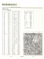
PRINTED CIRCUIT BOARDS AND PARTS LIST
W: Part s No. X: Parts
~nme
Y: Stock
~o .
Z: Position of Parts
FM MPX BLOCK <F-1387B)
Stock No. 7540670
w
R"ol
R•.,
R."
R...
R"05
R."
R"Ol
R.,.
R.,.
R",o
R"'2
R" ' 3
x
y
lk n
100k n
•.n n
22k n
6.8k n
100k n
4,n o
820 n
2.2k n
4710
z
w
R."
R
.,.
0100102
Ie
0100104
Ie
0100472
0100223
0100682
Ie
Ie
Ie
0100104
0100472
0100821
0100222
0100473
18. C
1a
28
2B , C
18
R461
R462
R."
VR401
VR402
VR403
0100182
1B
28.C
R.. ,.
0100 104
2B
R"15
2201;. 0
01002241A . 8
R.. u
220k n
nOk n
2201 0
0100224
0100224
0100224
0100103
0100103
I A. 8
I A. B
I8
IA
IA
0100103
0100103
0 100563
0100563
0100104
0100104
1A
1A
1A
1A
I A
1A
C411
C412
C413
C4\4
C41.5
C416
C41 1
C 418
C 419
010010..
1A
C.,.
0100104
I A
0100822
0100822
0100103
0100103
0100102
0100102
0100563
0100563
0100103
0 100103
0 100 105
0 100332
IA
I I<.
1 I<.
I I<.
21<.
1 I<.
21<.
2 I<.
21<.
21<.
2C
2 B, C
c."
0 100820
0100473
0 100822
0100.473
0100470
0100223
010022 3
0100102
0100822
0100150
0100223
0100121
0100223
0100223
01 00.4 73
0 100.472
2C
2C
2C
2C
2C
2C
2C
2C
1. 2 B
28
28
28
28
2B
28
28
R.. "
10l n
R" o
R.21
lOI n
10k n
IOl fi
561 n
Rm
R.13
R.24
R"2S
R"26
R."
R. 28
R."
R.,.
56ltn
100ln
100l n
100l n
100kO
821 n
8.21n
RUI
10l n
R.32
10kn
lk n
lk n
56" 0
56k n
R,"
R.,.
R.35
R."
R.31
10lt O
R".
l OI n
IMn
3.3k n
R UI
82n
"7 ..
8.2k n
R.3,
R.... o
RU2
R.... J
Ru ..
RU5
n
.c n n
.,n
Ru,
22" 0
R Ul
22 ..
lk n
8.2k n
15 n
Rua
Ru,
RHO
n
R.f.Sl
22"0
R"n
120n
22H1
nk n
R."
R."
R" 's5
R."
.. n n
4.nn
±IO%
Uw co.
.47 !1
.4 n n
.4n n
4n !}
39k n
100l n
R...
0100223
C • .,
c•.,
c."
Ail,
50 V 5C.
25 Y EC.
50 Y EC.
50 V se.
O. ".F) ±IO% 50 v MC.
O. I/IF
1600 PF) ± 5 % 50 V se.
1600pF
I IfF
50 VEe .
0.Q022 /tF ± 10% 50 v Me .
~::;~::}
25 v AEe.
1200 0F) ± 5 % 50 V 5C.
1200pF
O.OOIIIF)
± 10% 50 V M:.
C .2.
C . 25
C A26
O.OOI /IF
C "21
C "28
100PF}
4700pF ± 5 %
680pF
IJIF
10p F
O. II'F
0.0 .. 7 p F
47pF
0.022 p F ~~%
220p F
0.0.c 7I'F ~:%
c.,.
c.,.
C 43'
C'"
::%
C .33
C.34
C4l5
C".
29 -
CO.
Y ce.
50 V EC .
6800 0 F) ± 5 %
2200pF
10/IF
1/IF
560 PF)
560pF ± 5"
C.31
-
Uw
± 10% 50
68pF
3.3pF
c...
TRAtO
TR.,I
TR412
TR413
TRAIA
± 5%
Uw co.
220kfl (8) 5'.' .0 ' ..dlcolo.
220ln (8) fM Mul,"g Adl
C•.,
TR.."
TR ..oe
TR ...
± IO%
I Okn (8) 5'.'.0 S.po.oloOtl AdJ,
c.. O\
TR40,
TRA02
TRA03
TRAO<I
TR405
TRA06
y
• •n n
RA.59
1.8k n
22k n
100k n
R"'7
R.' 8
x
2SC871 (F)
25A.78 (6)
) 2SC871 (F)
) 2SC'3'A (6)
25011 (F)
~
2SC7l1 (E. F)
25C63' A (6)
25C7 11 (F)
2SC7l 1 (E. F)
50 v SC.
50 V EC.
25 V EC.
25 V I<.Ee.
50 v CC.
25 V EC.
50 v CC.
25 V EC.
50 v CC.
z
0 101.472
0100 .. 70
0 100.473
0100473
01004 73
0100393
0 1071 04
2A
28
28
2C
2C
IC
2C
1035130
1035210
1035210
1A
2C
28. C
0660680
0515339
0629001
0620222
0513100
0515109
0620561
0620561
0601108
0601108
0620162
0620162
0515109
0601226
0563H8
0563478
0620122
0620 122
0601106
0601106
0620101
0620472
0620681
0515109
0513100
0563108
0657473
051 3470
0657223
051 3221
065H73
1C
lC
IC
28
18
28
1 I<.
1 I<.
IA
1A
1 I<.
1A
1.28
2A
21<.
1. 2 A
2A
2 I<.
2A. B
21<.
IC
2C
2C
2C
28
28
28
1. 2e
0305472
0300291
0305472
0305472
0305891
0305891
0305732
0305731.2
0305731.2
0305731 . 2
030573 1. 2
030589 1
0305732
0305731. 2
w
x
25M78 (6)
2SC 711 (E. F)
O AOI
D•.,
) 1595 3
D."
D...
O AO.5
} IN. O?
D
."
0 .01
M?X Coil
2.2mH
Mic ro Inductor
MPX Coil
l
I ml<. M icro Induclor
M PX Con
F-13B7·2 PrinTed Circuit Board
y
z
030029 1
030S731. 2
28
0311050
03 11 050
0311060
0311 060
0311060
031 1060
031 0.c00
IC
IC
18
18
18
18
2C
.c2.c0660
4900090
.c900090
.c2.c06S0
.c900120
.c2.c0640
42.cOS70
.c240S70
1 B. C
1C
IC
I Ii
2C
1C
2A
1 I<.
2C
254 0260
1
2e
IC
1. 2 8
1 I<.
IA
2A
2 I<.
2C
2C
2C
2C
28
28
28
2
2B
Not For Sale
-
30 -
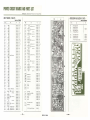
PRINTED CIRCUIT BOARDS AND PARTS LIST
W: Parts No. X: Parts Name Y: Stock :"0. Z: Position of Pans
AM IF BLOCK ( F·1417C)
ACCESSORY (A) BLOCK (F·1437)
Stock No. 7530230
w
RJOI
R""
RJOJ
R,..
RJO'
x
10,n
1. 2C
e 31.
0101102
t . 2e
e 3lS
3.3, n
0101332
2C
loon
e 31'
0101101
1C
e 311
10, n
10, n
22 n
Ie
2B , C
2C
1C
2C
1,2C
e llS
.. n
R,..
R,..
470 n
R J10
loon
Rl1I
47n
0101410
I8. C
RlO'
RJ12
RJ1 3
RJU
R315
.. n
.. n
0101102
18
22k n
0101223
lB . C
3.3' n
OIOII02 1 'C
0101332 Ie
0101102 28
.. n
RJI'
.. n
RJ17
150kn
RJIB
5.6' n
10, n
RJ1'
w
0101103
0101103
0101103
0101220
0101102
01014]1
0101101
R""
Stock No. 7591170
Z
y
0101151
0101562
28
I 8
0310330
0 311 090
03 10330
0310330
IC
2A
IA
IA
T306
AM Rf Coli
Ceramic filTer YEl· 455E2
AM OSC Coli
AM 1fT
AM 1fT
AM 1FT
4210180
0910180
.4220480
4230590
4230600
4230580
2C
28, C
I A. 8
2B
28
2A
L301
3.3pH Micro InduCTor
Lm
LJOJ
59mH Coli
4900100
4290200
4290200
2C
2A
2A
RJ'4
".nn
RJ25
10,n
R32.
1.8,n
loon
0101472
0101103
0101182
0101102
0 10110 1
2B
28
18
2A
lA , B
1.8,n
0101182lA , B
Rnl
Rm
R333
mn
0101102
0101103
0101183
10, n
0101103
10, n
R",
Rm
R",
.. no
R337
loon
R".
2.2' n
Rn,
R140
15k n
22k n
.. n
loon
R34'
8.2 n
VR301
10k D ( 8)
C 301
Cm
CJOJ
C""
C305
C306
C 30'
C,..
ClOt
C 310
e ll!
e'12
e'l)
0.022pF
I pF
0.047
AM Meier Adj .
:!::"
p'}
0.047 pF +80"
0.022pF - 20
0.047 p.F
IpF
0.04 7 I'F}
0.047 pF
0.047 pF
O.OlpF ± 10%
:!::"
470p'
0.01 1"
25 V CC.
50 V f C.
25 V CC.
50 Y fC.
50 v
cc.
50 Y MC.
± 5 % 50 v SC.
± 10% 50 v MC.
Cn'
C".
Cn,
C",
C",
C",
C",
010U73
0101153
lA
IA
IA
1A
2A
1B
0101223
0101101
0101222
0101102
0101101
0 107829
1B
1B
I A, 8
IA
2A
1C
1035130
1A
0 ""
0656223
0515109
0656473
0656473
Ie
Ie
Ie
2C
T3Q2
0656223
2C
0656473
2C
0515109
2C
0656473
0656473
0656473
0601107
0620 471
0601107
2C
2C
2C
IC
1B
IC
C".
TR JO\
TR m
TRJOJ
TR""
TR305
TRlO6
0 301
0 ""
OJOJ
T301
TJOJ
T""
T30'
0.047"'}
0.047 pF
0.047 p F
25 Y CC.
:!:~%
25 Y CC.
16 Y fC .
50 V fC.
+80ev
-20~
25 Y CC.
± 10 %
50 Y
0.047 pF
47pF
+.,
0.047I'f)
0.047 pF -20%
4.7 pf
0.0047 /lf
O.OI/1 f
0.00·47 pf
O.Olpf
O.OI/lf
0.01 pF
0.047 pf
1
25
ee
v ce.
25 Y fC.
J ± 10% 50 v MC.
0.047 /If
:!:~%
• 47 /'f
0.0471" }
0.022pf
0.022p f
HO%
-20;
0.022/ tf
100/tF
25
v CC.
6.3 V fe .
)2SC403C(4)
2SC403C (3)
)2SC403C(4)
2SC403C (3)
IN60
15 1007
IN60
F·1 41 7 PrinTed Circuit Boord
-
2591170
0305992
030599 1
C'"
.. n
f · l .437
1C
18
28
.. n
11 102 10
030599 1
0305992
28
0101.70
R32a
Rm
Rm
(N.R. AdapTor SwITch)
(Tope Mon· 1 SwITch)
(Tope Mon·2 SwITch)
2C
2C
0101101
47 n
R327
5,'
5,'
5.'
0305992
0305992
loon
RJ21
5"
t 8
I 8
1A
1A
1A
Cm
C'"
Cn,
Rm
18
I [,
28
18
2B
28
28
2A
2 A. 8
2A
1A
IA
2A
IA
2A
1. 2A
2A
I A
2A
IB
Cm
28
CR.
5,
1B
Cm
C32.
Cm
C32a
Cm
Cm
010110"
±10% ~w
IB
N.R. AdopTor SwITch
Tape Mon· ' SwiTCh
Tape Mon ·2 SwITch
4Ch. AdopTor SwITch
fM MUTing Off SwITch
0512 470
0656473
0656223
0656223
0656223
0515101
C,,'
C".
28
100, n
IC
I B
IC
0 656473
C'22
:!:~ "
y
5,
5,
5.
16 Y f C .
1p F
v CC .
I
x
w
z
25 Y CC.
e l21
28
RJ21
0.047/1;)
0.047 pF
10pF
C'20
0101152
1.5,n
lOP') ±10% 50
15pF
0.0 47 Jl F)
0.047/,F
0101103
R'20
y
0660100
0660150
0656473
0656473
0512100
0656473
0656473
0515109
0656473
0656473
0656473
0656473
0660470
0657.473
0657.473
0513479
0601.76
0601107
0601.476
0601107
0601107
0601107
0601477
e ll9
18
I B
x
1 "30610
11 1021 0
11 1021 0
PrinTed Circuli Boord
F- 1437
MI
", 2
o
o
2530160
31 -
Not For Sale
-
32-
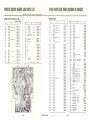
PRINTED CIRCUIT BOARDS AND PARTS LIST
W: Parts No. X: Parts Na me Y: Stock No. Z: Position
or Parts
ACCESSORY (B) BLOCK <F-1438>
EQUALIZER BLOCK <F-1435>
Stock No. 7591180
Stock No. 7550410
w
Roo,
R.o>
x
z
y
.. n o
.n o
28
lo,n
2A
18
1A
18
"n
R...
R...
.no
471: 0
0101473
IA
R601
'71n
0101473
0 101473
0101681
18
1A
1, 2 B
0101681
0101154
1, 2A
28
R.o<
R...
R...
R610
R611
R612
R6\3
RdH
R61S
R616
R617
R6la
R619
R620
R621
Rm
R6l3
R6l"
R62s
R626
R6:!]
3.3'n
3.3' n
.n.O
680n
680n
150,n
150, n
22o,n
2201:0
±10 %
22,n
22,n
Mw
CR.
±1 0 % }{w CR.
0101103
010 11 02
010 1102
0101333
0101333
w
2A
28
2A
2B
2A
C 611l
Cm
Cn !
em
0101333
2a
C 623
( 62.
0101333
2A
( 625
C 626
Coo,
C",
PF)
I.S
1.5 p F
25 v TC.
C603
2A
1B
0101224
IA
0 101223
1B
C...
IA
28
C..,
0 101273
0101273
0 101332
0101332
0 101181
0 10118 1
"no
'71n
mn
33, n
33,n
33,n
33,n
z
y
n.n
0101154
0101224
0101223
010147.
0101.74
'70,n
'70,n
271n
271n
3.3'n
3.3'n
180n
180n
x
0101.73
0101473
0101332
0101332
0101473
R60J
w
C...
C...
C...
C...
2A
2B
2A
2B
2A
2B
2A
C 610
C 611
C"2
C 613
C".
C 615
0 101473
28
010 \473
2A
C 617
0101103
28
C61a
C 616
IPF}
IpF
10pf
10/IF
50 v fC .
33
33pF
PF)
±IO% 50 V CC.
47
47pf
PF)
10 V fC .
33/IF)
33 / I F
470 PF)
470pF
6.3 v fC.
PF)
0.47
0:47 pF
10PF)
10pF
±5% 50 V MIC.
±IO% 50 v MC.
25 v EC.
0573159
0573159
05151 09
0515109
0515100
051 5100
0660330
0660330
0511-470
051 1-470
0510330
0510330
06-40-471
06-40471
06014 / 8
0601470
0513100
0513100
TR60!
1B
1A
TR",
TR..,
TR ...
IB
IA
IB
I A
IB
I A
IB
I A
18
I A
28
2A
28
2A
2B
2A
TR60S
TR606
x
O.0022.u F)
O.0022pF
± 10%
y
50 v MC.
470 PF) ±IO% 50 v Sc.
470pF
0.0068 /I F) ± 10% 50 v MC.
0.006apF
PF)
22
22pF
±
10 ~,)
50 V Cc.
} 2SA6 40 ( L. M)
'j2SCI222 (E)
) 2SA6'0 (l. M)
F·1435
PrinTed Circul I Boord
0601226
0601 22 6
0621471
0621 47\
0601686
060 1686
0660220
0660220
0300301.2
030030 I. 2
0306012
0306012
030030 1. 2
030030 1. 2
w
z
28
2A
28
2A
28
2A
2B
2A
mn
( 191
Cm
Cm
18
1A
IB
1A
2B
2A
0 101223
01 0 1223
01 0 1123
0101123
010 1474
0101474
2
-34-
v
0640391
064039 1
0601207
0601207
060 1806
0601806
C
Mi .
C 796
0.008p F
s.
Mono Switch
Loudness Switch
High Filler Sw itch
Low filter Switch
f·1438
A
+5% 50
-
CR.
( 795
S,
S.
2550320
390 PF)
39 0pF
Yow
..
0.02 P F}
0.02 f-1 F
0.008 pf ± 10% 50 v MC.
C 79.
S9
Not For Sale
± I0 %
12k n
470kn
470kfl
z
y
22,n)
22k!}
1
-33-
x
l
I
1130600
2591180
Printed Circuit Boord
B
a
a
a
a
A
A
a
a
a
a
A
A
PRINTED CIRCUIT BOARDS AND PARTS LIST
W: Parts No. X: Ports Nome Y: Stock
~o .
Z: Position of Parts
TONE CONTROL BLOCK (F·1436>
Stock No. 7560560
w
x
R IOI
2."0
0101272
R'02
R'03
R, ..
2 .711 0
0101272
150>0
150>0
330>0
330>0
loo>n
loo>n
010115.
R'05
R'06
R707
R,,.
R' 09
Rl 10
R7I1
010115"
010133·
010133.
010110.
01011 0"
0101 12.
120"0
120kO
010112"
R 711
18> 0
18> 0
2.1' n
2."0
3.3>0
3.3>0
.470n
R71a
.4 70 n
R719
3.3>0
3.3> 0
0101332
1.2.. 0
1.211;0
0101122
0101 122
3.9>0
3.9>0
1.2k 0
1.2k0
3.3> 0
0 101 392
0101392
R712
Rl 13
R'I 4
R7Is
R ll6
Rno
R721
Rm
Rn3
Rn .
Rn5
Rn ,
R 121
0101183
0101183
0101272
0101272
0101332
01 01332
0101471
0 101471
0 101 332
0101122
0101122
0101332
0101332
0101681
w
z
y
R' 56
2A
IA
2A
IA
2A
IA
2A
IA
2A
IA
2A
IA
2A
IA
2A
IA
2A
IA
2A
28
2A
28
2A
28
2A
28
1,2 B
18
1. 2 B
IC
28
Rm
R'50
R759
R'6Q
R761
R762
R' 63
R, ..
R' 65
R' 66
R767
R' 68
R 769
Rn o
Rm
R 172
Rn3
R 17.fo
R 175
R 176
R 177
Rns
R 119
C 701
C'02
C'03
C, ..
Rna
R",
R,JO
3 .311; 0
R7l1
2200
Rll2
220 0
0101221
1,2 B
R'33
R,,,
Rm
R,,.
5.6"0
0101562
0101562
28
1, 28
C' 09
0101103
28
C 710
0101103
0101562
1, 2 B
C711
28
C 71 2
1, 2 B
C 71 3
R7l1
R",
R739
Rl'0
R, .. ,
R"2
R,.)
R7U
R 7.fo5
6800
6800
5.6 11; 0
10>0
1011; 0
5.6>0
5.6> 0
1.2k O
1.211; 0
3.9'0
3.9'0
100'0
100kO
R 7.fo9
100'0
100'0
8.210
8.2kO
04 70k n
R,>o
oi70~n
R 751
68 0n
680 n
3.3'0
3.3'0
2.n n
R7.fo6
R 7.fo 7
R 7.foS
R752
R",
R, ..
R,,,
±IO % ){w CR .
0101681
0101721
0101562
0101122
0101122
0101392
0101392
01011004
0 1011004
0 1011004
01011004
0101822
0101822
010U704
010104704
0101681
0101681
0101332
0101332
0101272
C 705
C'06
C 707
C,,.
28
IC
I. 2 B
18
IA
18
18
18
18
18
18
18
IA
18
18
18
2C
C 71..
C 71 5
C 716
C 717
Cns
C 11 9
Cm
Cn.
Crn
Cm
Cn.fo
Cm
C 726
C'V
Cm
e",
C'JO
-
x
2."0) ±IO% ){ w CR.
1.5>0
1.5'0
.. n o
04nn
04 nn
04nn
"0
"0
220ltn
220'0
150> fl
150>0
5.6'0
± I 0% ){w CR.
5.6' 0
04 n o
04no
1000
1000
04.70
04.70
"70kO
470kO
loon
0.47 Pf ) ±IO% 50 V Me.
0 ... 7/fF
PF)
68
68pf
± IO % 50 v CC.
33J1F)
33/,f
33
33p F
PF)
6.3 V fC.
25 V fC.
10PFj
50 V EC.
10pF
O.Ol p F
O.OI /IF
O.Ol p F
O.OIJlF
±20% 50 V Me.
0.033/IF
0.03311F
0.033p F
0.033/lf
1
3.3 "}
3.3/fF
10pF
10pf
50 V fe.
047 PF) ±IO % 50 vee.
047pF
33J1F)
33pf
6.3 V fe.
2.2 I1F) ±20% 25 v Te.
2.2p'
~:~:~:~}±IO%
z
y
50 v MC.
0101272
01011 52
0101152
0 10U73
0101473
01010473
01010473
0101102
0101102
01012204
01012204
0 101 1504
01011504
0101562
0101562
0101473
010U73
0101101
0101101
01000i79
01000479
01010474
010loi74
0101101
j 1C
IC
Ie
2C
Ie
2C
I C
tC
Ie
1C
1C
Ie
1C
1C
1C
1C
IC
1 B. C
1A . B
2C
2B
IC
IC
1.2C
060U}8
060U 78
0660680
0660680
0510330
0510330
0510330
0510330
0515 100
0515100
0601107
0601107
0601l0 }
0601101
060133}
060133}
0601337
060133}
2A
IA
2A
IA
2A
I A
2A
1A
2A
1A
28
28
28
28
28
28
28
1,28
0515339
0515339
0515100
0515100
06600470
06600470
051 0330
0510330
05 }3229
0513229
0601oiO}
060 1040}
1.2 A
18
I B
28
1A
18
IA
I 8
28
18
w
x
e 731
0.03 P F) ± 10 % 50 v Me.
O.03pF
Cm
C 733
0.68 /lf) ±20% 25 v Te.
0.681'F
Cn .
C 735
c,,.
0. 022 I'F)
± 10% 50 v Me.
0.022p'
C 737
C,"
IP')
±20% 25 v Te.
100/IF
100/I F
35 V EC .
50 VEe.
I p'
C 739
C 7.fo O
0601301
0601301
0513688
0573688
0601227
0601221
0573109
0513109
05Ul01
0515101
0300301,2
0300301.2
030030 1.2
0300301.2
0300301 ,2
0300301 .2
0300301.2
0300301.2
0300301. 2
0300301.2
TR 701
TR 702
TR 703
TR 7Q.o1
TR 705
TR 706
TR 707
TR 708
TR 709
TR 710
F·143 6
z
y
Prln led Cir(uil Boord
2C
Ie
2C
1C
2C
1C
2C
IC
1A
1. 2e
2A
IA
2A
IA
1A
18
18
I8
2e
IC
2560520
LAMP HOLDER BLOCK (F·1205>
Stock No. 75905 20
w
PLOO6
PLOOl
PL""
PLOOf
x
y
7V 0.3A Pilo1 lom p
)
( Fuse Type)
PLolo
2e
IC
3 5-
Not For Sale
0"200040
04200'0
004200040
004200040
004200040
Fuse Holder ( x 10)
2310050
f · 1205
2590520
Ptlnled Chcuh Soard
-36-
PRINTED CIRCUIT BOARDS AND PARTS LIST
W: Pa rts No. X: Part s Name
Y: Stock :'\'0. Z: Pos ition of Pa rt s
DRIVER BLOCK <F-1439)
PROTECTOR BLOCK <F-1440)
Stock No_ 7570660
w
Roo'
R..,
Roo,
Reo<
R....
R,..
Roo'
Reoa
R...
Relo
Rail
RaIl
RaI l
ReI .
x
oi70kfi
lo>n
loo>n
8.2>n
4711:0
lo>n
6.8>n
6.8>n
220n
l oo>n
3.9>n
8.2>n
470n
y
0 101 22 1
2A
2A
IA
IA
IA
IA
IA
2A
2A
0 101 104
2A . B
0101 392
010 1822
2A
IA
18
18
I A.
I A.
I A.
18
18
18
2A .
2A .
28
28
28
28
0 10\ 04 74
010 11 03
010 11 04
0101 822
010\4 73
0101103
0 101 682
±IO %
Kw
C,.
0101682
01014 71
4n n
0 101472
0 10 11 0 1
0 10 11 0 1
Rell
loon
loon
470n
ReI!
Re"
,..OJ
RS15
ReI'
R020
R!2'
R",
R",
l.5>n
33n
6.8n
± 10%
±IO %
MW C• .
0 1034 7 1
Kw
010 1562
010\ 152
010 1330
C• .
0101689
010\ 472
4.no
RillA
Ion) ± 10 'Ion
R",
R",
6.8n) ±10%
6.8 n
"i N
C• .
Mw C.
01031 00
0103 100
0 10 1689
0 10 1689
Stock No. 7598110
z
W
X
R",
R",
R",
220n ) ± IO% j{w CR.
220 n
Ion ±IO % 2W CR.
VRaol
VR..,
0132 100
1031090
1031 050
IA
IB
1.5J1F
47pF
± 20 % 2SV Te .
±I O% 50 v CC.
05731 59
0660470
2A
1. 2A
C..,
0.00 1p F
~:% 50 v ee.
0657 102
2A
22 PF} ±1 0% 50 v cc.
15pF
100p F
10 SpEC.
O. l p F ±1 0% 50 v MC .
22pF ± 10 % 50 v CC.
50 V EC.
47/1F
22pF ± 10 %' 50 v CC.
0660220
0660 150
0531 10 1
060 11 08
0660220
05 15 470
0660220
2A
2A . B
2A
2A
18
2A
IA
065 7222
18
Coo,
C ...
C...
C al O
C al l
TR IOI
TR..,
TR803
TR ...
TR",
TReo.
TR""
0.0022p F
::%
I) 2SA640 (L.. L
t)
) 25A678 (6.7)
) 2SC98 3 (0 . ' )
25C98. (C)
50 v CC.
x
W
28
28
2A
C..,
Ceo.
8
8
5> 0 (8)
" 0 (8)
0 10 122 1
0 10 122 1
Z
COO,
c...
c....
8
8
8
Y
TR ...
TR ...
25C1I2. (2. 3)
2$A706 Gr ee n (2 )
y
0305901 , 2
0300401
2A
28
Roo,
Rm
0311050
IA
IA
IA
28
18
Roo<
R....
R...
Roo,
R,..
R..,
R90l
0 80'
D8O'l
D80'
D...
D805
) 15953
03 11050
'D ·9A (M)
} 1$953
F· 1439
Printed Circuit Boord
0315220
0311050
0311050
2570450
R910
Rm
C 901
em
C..,
C, ..
C,,,
C...
C..,
0300302.4
0300302 .4
0300291 .2
030029 1.2
030602 1.2
0306021.2
0305872
x
w
z
IA
2A
18
2A
IA
I A. S
IA
TR901
TRm
B
4no
3.3>n1
3.3>n
82kfl +
Ion _ 10%
J
2
-
37 -
Not For Sale
-
38 -
Kw
Kw
C •.
C• .
Kw
CR.
Ion) ± 5 %
Ion
5.6kn
± 5%
Mw C• .
MW CR .
47/IF
I/IF
220/ ,F
100 /IF
1/IF
O.1 f/ F} ± 10 %
O. I / IF
6.3 v
50 v
6.3 V
50 V
50 V
BPfC.
EC.
fC .
EC.
BPEC .
50 v MC.
) 25C63' A (7. 8)
D90'
Dm
D..,
D, ..
• } IN34A
D90s
0 ...
} F· 14A
0100473
0106823
0100332
Z
0100823
0100100
0101100
0101100
0 103100
0103100
0107562
A
A
A
A
A
A
8
8
8
8
A
05304 70
0515109
051 0221
05 15101
0535109
0601108
060 1108
A
A
A
A
A
8
8
0305892. 3
0305892. 3
A
A
0310402
03 10402
03 10402
03 10402
0310940
03 10940
A
A
A
A
A
A
0100332
Ion
Ion
190'
lm
2.5/I H InduCTor
4'2902 10
4290210
8
8
RY9Q1
Roloy
1150101
B
F·\440
1
±IO%
± 5%
82>n
y
PrinTed Ci rcui T Boord
2598110
PRINTED CIRCUIT BOARDS AND PARTS LIST
OTHER PARTS AND THEIR LOCATION ON CHASSIS
W: Parts No. X: Parts Name Y: Stock No. Z: Position of Pans
OTHER PARTS
POWER SUPPLY BLOCK (F-1441)
Stock No. 7500670
w
ROOl
R...
ROO5
R",
Roo,
Rooa
x
330n) ±10 %
390n
47n) ± 10%
47n
ROIO
ROll
1.5\:n
R OI2
47n
ROl3
<7n
ROil
loon
loon
loon
ROI5
ROI6
Coo,
C",
Coo,
Cooa
220/lF }
220 pF
IODpF
C",
/
220 " }
C Ol O
220JlF
C Oll
220"F
IOOOJlF)
IOOO"f
C Ol 2
C OIJ
3W CoR.
IW CR.
•. nn
2.2kfl
I.5kn
I.5kn
R",
y
nO/If
±IO %
Yow
CR.
25 V Ee .
50 v EC.
6.3
v EC.
w
z
1, 28
1,2 6
C Ol 4
0104470
2B
C Ol 6
0104470
0100472
0100222
2B
18
IB
C Ol7
0100152
0100152
18
1A
CO?<>
0100152
2A , 8
01004 70
0100470
0100101
0100101
0100101
2B
1A
I A
IA
2A
TRoc)!
TR",
TROOl
C OIS
C OIS
C Ol 9
R",
6.3 VEe.
0510102
1A
ROI7
v EC.
0519302
1,2A
ROl e
0519301
0511471
1A
1A
0657·"3
0657473
28
IB
75
10 V EC .
50
v CC.
250330 (E)
2SB5U (D. E)
0308362
0308362
0303251. 2
0310940
0310940
0 00'
0 010
0 01 1
0 012
RO·13A ( N)
RO ·2<A ( M)
F·) .... 1
Printed Circuil Boord
R026
R l001
R,,,,
R7oo3
0 00'
Oooa
0",
Rm
R02'
R02,
28
28
2B
03109 .. 0
03109"0
03109" 0
03109"0
03109 .. 0
0315310
0315"1 0
Ron
I8
I A. 8
2B
F· 14A
ROl9
Rm
R02,
1B
031094 0
18
1A
1A
0.0 .. 7/1F) ::%
0.0"7 pF
IA
03109.0
05131 01
05 10102
0510102
w
z
DOG<
0",
1A . 8
220/lf)
100pF
.. 70pf
05101 02
0 003
1B
1B
1 A. 8
18
28
1000 P f )
1000pf
0",
0513221
0513221
0515221
0515221
0515221
y
Roo,
0183331
0183391
05 15221
x
R, ...
Rl00S
2A
2A
I A
lA
2A
I B
1B
R,,,,
R7007
R7017
2.2. . n
Rl01 S
Rl019
R,m
Rl021
R,m
Rl023
Rl024
Rl02S
R7026
R7021
R702S
2.711'. 0
2.711'. 0
3.3kn
3.3kn
3.3kn
3.311'.n
<.7In
4.nn
R7030
4.711'.0
Rl031
4.no
4.nn
Rl040
4.711'.0
4.711'.0
3.9'n
3.911'.0
3.3kn
3.3"'0
2.7In
2.7II'. n
R7!)/,1
2.no
Rl042
2.7In
3.3'n
R,o><
R,OlS
R,,,,
R,,,.
R7OJ7
R1OJ9
R704J
± 10% J{w
Cit
J{w CR .
01 71332
01 71332
0101220
017 1561
0 171561
0101472
0101 104
010 11 04
010 1334
0101334
0 101470
0 107102
R7044
R7!)/,S
± 10%
J.{w Cit
R,05I
R7GS9
2.nn
Rl051
R,,.,
R,,,,
Rl050l
Rl055
R,o..
R,,,,
R,,,,
R..,
R..,
R..,
R...
VR 701 , 702
VR 7OJ,704
Coo,
C",
COOl
C...
CO2.
C021
CO2'
C.,.
o..,n}
0.47 0
0.<7n
±IO%
250kn (MN)
250kn (8) x 2
::"
TRe'2
50 V EC.
150V CC.
::%
0.04 7/1F
TRsu
Balanc. Control
Vo lume Control
. <700" '}
700
"
l'f
1000Jlf
1000/,F
0.0047 pf ~:%
COl'
TRslO
TRell
3W Cd.
0.<7n
!:"
±
C 039
50 V CC.
150V CC .
20% 250V MPC.
y
0 100332
0100472
01 00472
0100562
0100562
0100562
0100562
0100562
0100562
0100562
0100562
0100392
0100392
0100392
0100392
0100272
0100272
0153478
0 153478
0 153478
0 153478
1010830. I
1010820. 1
0559319
0559319
0559320
0559320
0659802
0657473
0657473
0659802
0605337
50 V Cc.
0657473
0.0471'f )( 4
50 V CC.
0.022I'f) HO%
0.022pF -20
50 V CC .
0800121
0657223
0657223
25C793 ( R. Y)
25A663 ( R. Y)
0 00'
Pow.r Tran1i1tor SOck.1 ()( 4)
582
C FlO7
SFA ·10 .7MC
SI
SIO
0305450. I
0305450. 1
0300350. I
0300350. 1
2030020
0310660
0910 100
S..
PTool
Power Tran1former
4001121
lOG<
AM Bor Anl.nne
3.5pH P.aklng Coli
FM Bolloon
4200540
4290011
.. 290021
S12
SI3
l oo,
Llo)
Y-4-11 -5
Y-2-2-6
F- 2-2-11
F- 2- 2- 11
f - 2- 2-11
1104320
1102410
1102210. I
1102210. 1
1102210. 1
1130350
Seleclor Swilch
Spea .... rs Switch
Bass Swilch
Midrang. Swllch
Trebl. Switch
Pow.r Switch
S..
40 -
2.7In
COlO
Co,"
0100272
0100272
01 00332
± 10% J.{w CR.
0.0 .. 7P f)
0.047pF
0.0047 pf
0.033,,'
C 032-035
0100472
0400"72
0100472
0100472
0100392
0100392
0100332
0100332
0100272
0100272
-
<.7111
5.6kn
5.6"'0
5.6kn
5.6kn
5.6kfl
5.6 ... n
5.6kn
5.6kn
3.9kn
3.9kn
3.9kn
3.9kn
R7049
01 00272
0100272
0100332
01 00332
01 00332
0 100332
0100472
0100472
0100"72
0100472
3.3kn
4.nn
R1D'7
R,,,,
0100682
0100682
0100 .. 72
0100472
0100332
0100332
0100222
0100222
0100102
0100102
x
Rl!)/,6
RID'S
0100152
0100152
0100222
0100222
0 100272
0100272
0100"72
0100"72
0100682
0100682
an
an
4.nn
R,,,,
51 .
n
R,.,.
R,,,,
CI .
lW MfR.
I.5kn
1.511'.0
2.211'.0
2.211'.0
2.nn
2.711'. 0
4.711'.0
R 701 S
RIOl3
Yow
470
6.811'.0
6.8kn
4.711'.0
4.711'. 0
3.3 ...
3.3kn
2.2kn
Rl012
lW MFR.
Mw
no ± 5 %
w
y
330~ 0
RIOlO
RIO'!
Not For Sale
i~~:g)
4.7l1'.n
R701 6
39 -
5600) ± 10%
560n
nn ±IO%
6.811'.n
6.811'.n
R70 u
-
3.3 ... 0) ± 10 %
3.3kfl
22fl ± 10%
R,ooa
R,,,,
2500550
x
OTHER PARTS AND THEIR LOCATION ON CHASSIS
• Oesll" end
W: Parts No. X: Parts Name V: Stock
w
L701
L'02
Moo.
MOO2
Joo.
JOO7
JOO3
J""
PUOOI
COOOI ,002
Foo.
Feol- 804
FOI
I
)
X
Choke Tronsformor
±100pA Tuning MeIer
200/tA Signol MeIer
PlOl2
Vahog. Selector Socke'
Voltage Se le ctor Plu g
AC Outlet (x 2)
24500"0
SA Power Fuse ( 100/ 117 V)
3A Power FU1e (220/ 2"OV)
Power Fuse Holder
"A Qu ick Acting Fuse ( )( ,,)
Quick Acting FU1e Holder
0"31280
0"31260
Fos
2A
PLOO2
430031 0
2410080
F02
PlOOl
4300320
PLOO3
PL""
PL oo>
PLoll
2430040
1
JWired In Fu se
2A
7V 0. 16A PH()t..jO-2 Indicator
7V O, I6A PHONO· ) Indicator
W
4010090
4010090
DIN Socke'
Tope Rec·2 Jod.
Tope Mon·2 Jad.
Heodphone. Jock
5A
IA
F06
Y
PlolJ
PlOlt
2430060
2430060
2430010
Plols
7 V 0. 16'" FM Indicator
7V 0. 1&'" AM Indicator
7V 0. 16'" AUX Ind ica tor
2300020
0"32900
0"32830
0432850
0 432850
0"0015"
0"001 55
0"00154
0400 155
0400 17 0
AC Power Suppl y Cord
380002 1
P",43 13U06
F·USOA
F-13878
F- U178
F-U35
F-l"36
F- l "37
F-l"38
' · 1439 (x 2)
( x 2)
PTOOI
0400153
7V 0.16'" POwer IndicatOr
7V 0.3A F·Type Signal Mete, lamp
7V 0.3A F. Type Tu ning Me l.r lamp
6.3V 0 .075A 0 101 PolnT.r Lamp
6V 0.1A FM S'.reo Indlca To l
fM IF Unit
MPX Unit
AM IF Unit
Equali zer Unit
Mu lt i-Co nnecto r
To ne Unit
Acce ssory Unit (A)
Acce ssory Unit (8)
Driver Unit
Multi -Connec tor
Protec tor Unit
Power Unh
lamp Holder Unit
Protecto r Fuse Uni t
F·I "56
0" 3327 0
Y
X
fM franlend
2"10090
IPec:lncetlons subject to ch.na;e without notice for
Improvements.
~o .
04200' 0
04200-'0
0"0022 0
0400 161
F0 6
F05
F02
FO I
C031-
2510060
75205"0
75"067 0
7530230
7550" 10
2"20030
7560560
7591 17 0
7591 180
7570 660
2"20040
F- U"O
F-U"i
7598 11 0
' · 1205
2590520
12.R7021- 7040
11 .R7041 - 7060
- 5 14
19
J OO2.003
• .
,
,
T
/ '
S 1 VR703.704 VR 701,702 l 702 l701
513,R700 1- 7020
J OO4
I
PLOll
S 10.R02 6
7500670
Fo r Powe r Transformer
2598 120
_ 1 - -TRBI2
-'\''----L101
~--- TFIB10
)::iiiiiio-==--:--:-''--- TRBl1
_
•
- P~4313U06
I!! ''-- 3:
-
F-1436
PLOI3- -- iI!!'
PL012- ---",=;
-41-
Not For Sale
-42-
LOOS
It
SANSUI ELECTRIC CO., LTD.
14· 1. 2-chome. Izumi. Suginami-ku , Tokyo 168. Japan.
TElEPHO~ 1 ( 03) 323· 11 11 /TELEX, 232·2076
Stock No. 9207090
Not For Sale
P, inled in 1000n ( 43640M5)