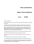
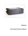
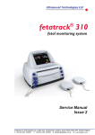
1
Fetatrack / Vascutrack 120 Series Service Manual
FETATRACK & VASCUTRACK 120 SERIES SERVICE MANUAL
File - Q:ethel.serv\qualsys\servman\FTVT120.doc
Issue 1 March 96
Page 1 of 34
Fetatrack / Vascutrack 120 Series Service Manual
CONTENTS
Section 1. General Introduction
1.0
1.1
1.2
Introduction
Re Order Information
Symbols
4
4
5
Section 2. Description of the Instrument
2.1
2.2
2.3
2.4
Audio Unit.
Dismantling Instructions
Audio Unit
Transducers
6
6
6
6
Section 3. Circuit Description
3.1
3.2
3.2.1
3.2.2
3.2.3.
3.2.4
3.2.5
3.2.6
3.2.7
3.3
3.3.1
3.3.2
Introduction
Audio Unit Power Supply
Battery Low Indicator
Ultrasound Transducer
Oscillator and Detector
Oscillator and Transmitter Amplifier
Receiver and Detector
Audio Amplifier
Velocity Processor
Controls and Indicators
Unit ON / OFF
Battery Low
7
7
7
7
7
8
8
8
8
9
9
9
Section 4. Test and Calibration
4.1
4.1.2
4.2
4.2.1
4.2.2
4.3
4.4
4.5
4.6
4.7
4.8
Introduction
Performance Checks
Test Procedure
Equipment
Audio Unit Power Supply
Battery Low Indicator
Active Regulator
Audio
Velocity Processor
Transducer Oscillator and Transmitter
Transducer Receiver and Detector
10
10
10
10
10
10
11
11
11
11
12
Section 5. Fault Finding
5.1
5.1.2
5.1.3
Fault Finding Guidelines
Ultrasound Transducer
Audio Unit
File - Q:ethel.serv\qualsys\servman\FTVT120.doc
13
13
13
Issue 1 March 96
Page 2 of 34
Fetatrack / Vascutrack 120 Series Service Manual
Section 6. Parts Lists
0120-0003
0120-8205
0120-0004
0120-8201
0120-0002
0120-8202
0120-0007
0120-8204
0120-0038
0120-8207
PD120 Audio Unit Assembly
PD120 Auto Off Audio Velocity PCB Assembly
Dedicated 2 MHz Assembly
PD120 Audio PCB Assembly
2 MHz Transducer Assembly
2 MHz Transducer PCB Assembly
5.4 MHz Transducer Assembly
5.4 MHz Transducer PCB Assembly
8 MHz Transducer Assembly
8 MHz Transducer PCB Assembly
16
16
19
20
22
22
24
24
26
26
Section 7. Drawings and Circuit Diagrams
0120-8202
0120-8204
0120-8207
0120-8201
0120-8201
0120-8205
2 MHZ Transducer Scematic
5.4 MHz Transducer Schematic
8 MHz Transducer Schematic
PD 120 Audio PCB Overlay
PD 120 Audio Velocity Schematic
PD 120 Auto / Off Audio Velocity Schematic
File - Q:ethel.serv\qualsys\servman\FTVT120.doc
Issue 1 March 96
29
30
31
32
33
34
Page 3 of 34
Fetatrack / Vascutrack 120 Series Service Manual
SECTION 1
GENERAL INTRODUCTION
1.0
INTRODUCTION
This service manual is written to aid in the maintenance and repair of the SEWARD
MEDICAL SYSTEMS FETATRACK and VASCUTRACK 120 series of Doppler detectors.
Servicing of this equipment should be performed by a qualified technician after carefully
studying this manual.
The drawings and circuit descriptions in this manual are correct as of the date it was
prepared, but the manufacturer reserves the right to make changes to improve the operation of
the instrument. If your instrument does not exactly match the manual, contact the
manufacturer or distributor for revision information.
Inspect the instrument upon receipt for damage, dents, or scratches. If damage is found
notify SEWARD MEDICAL SYSTEMS promptly at the following address :Seward Medical Systems Ltd
Techbase
Cleppa Park
Newport
Gwent NP1 9UG
United Kingdom
Telephone (01633) 810770
FAX
(01633) 810498
Retain the packing material for possible future use.
In the unlikely event that the instrument must be returned to for service or shipped for any
other reason, use the same packing material in which the instrument was delivered. If this is
not available, the instrument should be packaged in a proper size box with adequate
protective padding.
1.1
RE - ORDER INFORMATION
Listed below are the consumables used with the FETATRACK/VASCUTRACK 120 series
Pocket Dopplers complete with part numbers for ease / simplification of ordering.
Part Number
Description
9000-0005
9000-0006
9020-1604
Aquasonic Gel 0.25L
Aquasonic Gel 60 gm
MN1604 Alkaline Battery
File - Q:ethel.serv\qualsys\servman\FTVT120.doc
Issue 1 March 96
Page 4 of 34
Fetatrack / Vascutrack 120 Series Service Manual
1.2
SYMBOLS
The following symbol has been used on the rear of the FETATRACK/VASCUTRACK 120
and is here defined according to IEC601 and B.S.5724.
IEC Symbol 878-02-02 Type B Equipment
1.3
CE MARK
As indicated in the operating manual and identified on the outer packing, this product
complies with the essential requirements of the European Council Directive 89/336/EEC
relating to EMC.
1.3.1
Guidelines for identifying and resolving adverse EMC conditions
This product is classified as a Class A Group 1 type of product according to EN55011. This
product is allowed in domestic establishments under the juristiction of a Healthcare
professional.
Emissions
Care has been taken through the design and manufacturing process to minimise the EM
emissions which may be produced by this equipment, however, in the unlikely event that the
unit causes an EM disturbance to adjacent equipment, we suggest that the procedure is
carried out ‘out of range’ of the affected equipment.
Immunity
If the user has any doubt regarding the unit’s EM immunity during routine operation, we
suggets that the source of EM distrubance is identified and it’s emmisions reduced.
If the user has any doubt regarding the identification and resolution of adverese EM
conditions, they should contact Seward Medical Systems directly who will advise on the
situation. The address can be found in the front of this manual.
File - Q:ethel.serv\qualsys\servman\FTVT120.doc
Issue 1 March 96
Page 5 of 34
Fetatrack / Vascutrack 120 Series Service Manual
SECTION 2
DESCRIPTION OF THE INSTRUMENT
2.1
AUDIO UNIT
BATTERY LOW - LED indicator to show when the battery has reached a point when it
requires changing.
VOLUME - Rotary edge potentiometer which increases or decreases the setting of the
volume.
HEADSET - An audio output for connection to an audio stethoscope, for private listening.
TAPE OUTPUT - 3.5mm Stereo jack for connection to a standard tape recorder in mono, on
the Ring of the stereo jack is the Waveform output for connection to an ECG recorder.
TRANSDUCER CONNECTOR - For the connection of any compatible Seward Medical
Systems detection transducer. Note some variants have a fixed transducer.
2.2
DISMANTLING INSTRUCTIONS
Note:- Before dismantling the unit, unplug the transducers and accessory cable (if present).
2.3
AUDIO UNIT
The Audio unit houses the main circuit board, to remove the circuit board turn the unit on it's
front and remove the three M3 countersunk screws. The back panel will now come away
revealing the reverse side of the PCB. Remove the two M3 screws securing the PCB. The
PCB is attached to the unit via an 8 way connector, carefully remove the connector and the
PCB can be pulled clear of the case.
2.4
TRANSDUCERS
Circuit board removal is carried out by unscrewing the two M2 screws in the end of the probe
cover and carefully sliding the probe cover back up the cable. This will reveal the circuit
board mounted in it’s cradle. WE DO NOT recommend removing this from the cradle,
however if it is necessary to do so, with extreme care unsolder ALLthe wires (cable and
faceplate terminations) joining the PCB and press it out of the cradle.
File - Q:ethel.serv\qualsys\servman\FTVT120.doc
Issue 1 March 96
Page 6 of 34
Fetatrack / Vascutrack 120 Series Service Manual
SECTION 3
CIRCUIT DESCRIPTION
3.1
INTRODUCTION
The circuitry has been divided into functional blocks with each block being described
separately, the blocks are as follows:
Audio Unit Power Supply
Battery Low Indicator
Ultrasound Transducer
Oscillator and Detector
Oscillator and Transmitter Amplifier
Receiver and Detector
Audio Amplifier
Velocity Processor
Controls and Indicators
Unit ON / OFF
Battery Low
3.2
AUDIO UNIT POWER SUPPLY
The unit operates from a 9 Volt dry battery, it is recommended that only Alkaline cells be
used. The audio circuits are fed directly while the transmitter / receiver circuits are via
a nominal 5V regulator formed around TR1.
The unit is turned on by a membrane which is mounted on the probe cover. Closing the
switch grounds the gate of VFET TR2. The unit turns off when the switch contacts are
released. Some models are fitted with a latch ‘On’ circuit. These models stay On for
approximately 5 minutes afterwhich they turn Off automatically.
3.2.1
BATTERY LOW INDICATOR
IC2a is connected a voltage comparator with D2 as the reference voltage. When the power
rail falls below the threshold set by R6 & R7 the LED1 turns on indicating that the battery
requires changing.
3.2.2
ULTRASOUND TRANSDUCER
The ultrasound transducer operates on the continuous wave Doppler principle and consists of
a single half disc transmitter crystal whose beam is focused by angling and a half disc
receiver crystal. The transducer operates at a nominal frequency of 2.0, 5.4 or 8 MHz.
3.2.3
OSCILLATOR AND DETECTOR
The oscillator and detector is built up of four discrete sections. These are the master
oscillator, transmitter amplifier, receiver amplifier and detector.
These operate to produce a continuous wave ultrasound signal that is passed to the
transmitting crystal in the transducer.
File - Q:ethel.serv\qualsys\servman\FTVT120.doc
Issue 1 March 96
Page 7 of 34
Fetatrack / Vascutrack 120 Series Service Manual
The signal is then reflected from moving interfaces within the body to the receiver crystal in
the transducer, amplified and then detected so the audio doppler shift of that moving interface
can be heard audibly and / or converted into a velocity signal.
3.2.4
OSCILlATOR AND TRANSMITTER AMPLIFIER
Field effect transistor TR1, with L1, C2, C3 and associated components form a Colpitts
oscillator. This oscillator runs at a nominal frequency of 2, 5.4 or 8MHz producing a
sinewave of amplitude of approximately 2V.This signal is then fed to output transistor TR2
which drives the transmitter crystal in the transducer.
The output power isvaried by adjustment of VR1 during test. The signal is fed to the
transducer via a tuned transformer L2 (C5), the output impedance of which is set correctly to
match the transducer crystal impedance.
3.2.5
RECEIVER AND DETECTOR
The reflected Doppler signal is fed via a resonant transformer L3 (C9) to the gate of TR4,
the drain of this FET connects to the source of TR3 to form a cascode
amplifier the drain of which contains the resonant circuit L4,(C8).
From the drain of TR3 the amplitude complex of the received signal is detected by passing
the signal through diodeD1 with the high frequency signals being filtered by R7 and
C10,their frequency breakpoint being at 1khz.
The raw low frequency heart complex is then amplified and filtered by IC1 where ts
associated components form a bandpass filter amplifier with a bandwidth of 150Hz to 1KHz
for the obstetrics or 300Hz to 4KHz in the vascular transducer. This signal is passed to the
audio unit via the coiled cable.
3.2.6
AUDIO AMPLIFIER
After the audio signal has been detected in the transducer it is routed via the curly cable to
PL1 pin 2 on the audio circuit board, here it splits to feed the velocity processor, tape
recorder jack and via the volume control VR1 to the audio power amplifier IC1, which feeds
the loudspeaker.
3.2.7
VELOCITY PROCESSOR
One half of Op-Amp IC2B forms a buffer amplifier to the incoming signal with a gain of 100.
This amplified signal is then passed via the threshold control VR3 to the frequency to voltage
converter IC3. The convertion factor is approximately 70mV/kHz with fine adjustment
provided by VR4.
The output of this circuit is then scaled by R19,20 to 1mV/kHz, a suitable voltage level for
most ECG machines and recorders.
3.3
CONTROLS AND INDICATORS
File - Q:ethel.serv\qualsys\servman\FTVT120.doc
Issue 1 March 96
Page 8 of 34
Fetatrack / Vascutrack 120 Series Service Manual
3.3.1
UNIT ON / OFF
A membrane switch is situated on the probe, this switch grounds the gate of FET TR2
connecting the circuits to the power source, releasing the switch will turn the unit off.
On later models a latch circuit has been provided; depressing the switch once, switches the
unit ON, depressing the switch a second time switches the unit OFF. The latch circuit also
has a time out period of approximately 5 minutes.
3.3.2
BATTERY LOW
The LED illuminates when the rail voltage from the battery falls too low for continued
operation, indicating that the battery should be changed.
File - Q:ethel.serv\qualsys\servman\FTVT120.doc
Issue 1 March 96
Page 9 of 34
Fetatrack / Vascutrack 120 Series Service Manual
SECTION 4
TEST AND CALIBRATION
4.1
INTRODUCTION
The following sections details tests to ensure that the unit is operating within specification.
These tests may be performed in whole or part, however, if any repairs are carried out to the
power supply circuits then it is recommended that the whole test / calibration procedure is
undertaken.
4.1.2
PERFORMANCE CHECKS
The following procedure is intended to provide a means of determining the functional status
of the unit. It should be included as part of a preventative maintenance plan and should be
performed on a regular basis at least once a year.
Ensure that a full capacity alkaline cell is fitted .
Connect the transducer to the unit and press the switch to turn the unit on. Increase the
volume to to maximum. The battery low light will flash ON for about 5 seconds and then go
out.
Place transducer with ultrasound gel on the palm of the hand over the radial artery , a clear
pulse will be heard.
4.2
TEST PROCEDURE
4.2.1
EQUIPMENT
Oscilloscope 2 channel 50 MHz bandwidth minimum resolution 5mV/cm
Digital Multimeter 4 Digit measuring 1mV , 1mA , 0.1ohm
Frequency Counter 0 - 10MHz resolution at 2MHz 1KHz.
Signal Generator 10Hz to 10MHz 1mV to 10V Sinewave
4.2.2
AUDIO UNIT POWER SUPPLY
Connect a DC voltage source adjusted to 9V + 50mV in place of the dry battery and shorting
link between pins 3 and 4 on the connector PL1.
Place multimeter probes across C3. The voltage at this point must be no more than 0.2V less
than input voltage from the DC power source.
4.3
BATTERY LOW INDICATOR
NOTE: DURING THESE TESTS C13 MUST BE REMOVED FROM THE CIRCUIT.
Connect multimeter negative (-ve) probe to C3 -ve
Reduce DC Power source to give 7.0V (+10mV) at C3 +ve and adjust VR2 until LED D3 just
turns on. The voltage at IC2 pin1 must be greater than 5 volts.
File - Q:ethel.serv\qualsys\servman\FTVT120.doc
Issue 1 March 96
Page 10 of 34
Fetatrack / Vascutrack 120 Series Service Manual
Increase voltage to give 7.2 V (+ 10mV) at C3 +ve and LED D3 must turn OFF. The voltage
at IC2 pin1 must be less than 2.9V.
Connect C13 into the circuit and adjust the DC power source for 7.0V (+/-10mV) at C3 +ve.
The LED D3 must light within 20 seconds.
Increase the voltage to 7.2V (+10mV) at C3 +ve and the LED D3 must turn off within 20
seconds.
4.4
ACTIVE REGULATOR
Connect 270 ohm 0.5 watt resistor between pins 1 and 4 on the connector PL1.
With DC input voltage at C3 +ve set to 7.6V (+10mV) attach multimeter probe to PL1 pin1
(yellow wire). The voltage must be between 4.6 and 5.2 volts.
Increase DC input voltage to 9V (+50mV). With the multimeter still attached to PL1 pin 1 the
DC voltage must not rise to greater than 5.6 Volts.
4.5
AUDIO
Connect 8 ohm 1 watt resistor in place of the loudspeaker between pins 5 and 6 on the
connector PL1 and using the A.F. signal generator inject a 500Hz sinewave of 100mv peak to
peak into junction of VR1 and C6. Set VR1 to Maximum.
Connect oscilloscope across 8 ohm resistor and with the voltage at C3 +ve set to between 8.6
and 9v the resulting signal must be between 4.0 and 4.8 Volts peak to peak, with no visible
distortion.
Increase input signal until the signal clips. The measured voltage must be greater than 7 volts
pk-pk.
4.6
VELOCITY PROCESSOR
With oscilloscope set to AC input adjust input signal from audio generator to a frequency of
1kHz and an amplitude of 15mV + 1mV pk-pk at pin 6 IC2B.
Move probe to pin 7 IC2B the voltage will be in the range 1.2 - 1.8V pk-pk.
Set frequency to 10KHz and attach oscilloscope to pin 7 IC3 and adjust VR3 until IC3 Pin 7
just changes state from 0V to D.C. level between 400 - 900mV. The signal will be rough DC.
Using the multimeter with -ve probe connected to C3 -ve and +ve probe to the junction of
R18, R19 and C19, adjust VR4 until the until the DC level measures 700 mV +/- 2mV.
Set the frequency to 1KHz and check that the multimeter now reads 70mV + 4mV
4.7
TRANSDUCER OSCILLATOR AND TRANSMITTER
Using the multimeter measure the voltdrop across R6. This must be no greater than 0.6 V dc.
Turn VR1 fully anticlockwise and connect the oscilloscope to TP1, the signal must be an
undistorted sinewave of 1.7 to 2.2 Mhz (or 5.4 & 8mhz depending on transducer) and of
amplitude greater than 1.7V.
File - Q:ethel.serv\qualsys\servman\FTVT120.doc
Issue 1 March 96
Page 11 of 34
Fetatrack / Vascutrack 120 Series Service Manual
Replace oscilloscope with the frequency counter and adjust L1 for the correct operating
frequency of the crystal faceplate at TP4 .
Using the oscilloscope connected across output to the transmitter crystal (TS1, TS2 on edge
of PCB). Adjust VR1 and peak L2 to result in an output of 1.5V pk - pk.
4.8
TANSDUCER RECEIVER AND DETECTOR
Attach oscilloscope probe to the drain of TR3 (TP5) and adjust L3 and L4 for maximum
signal.
Move oscilloscope probe to junction of D1 and R7 (TP7). The measured output will be a DC
voltage of greater than 5.5V.
File - Q:ethel.serv\qualsys\servman\FTVT120.doc
Issue 1 March 96
Page 12 of 34
Fetatrack / Vascutrack 120 Series Service Manual
SECTION 5
FAULT FINDING
5.1
FAULT FINDING GUIDELINES
This section is an aid to trouble shooting and should be used in conjunction with the relevant
circuit diagrams found at the rear of this manual (Section 7). In each case the recalibration
must be carried out after any repair.
The following tables list some of the symptoms and the relevant circuit areas.
NOTE Do not, under any circumstances attempt to repair the instrument whilst it is
connected to a patient.
5.1.2
ULTRASOUND
Symptom
Suspect Circuit
Check
Ultrasound does not function
Transducer
Try another transducer
Transmitter / Receiver
Transmitter drive TS1, TS2
3V pk/pk. See Ultrasound
calibration tests
Unit On / Off circuit
Gate of TR1 in audio circuit
Transducer position
Re position transducer
Crackling operation of
volume control VR1
Replace volume control
Broken coductor in cable
Check audio signal on pin 3
of IC 1
Audio signal on PL1 pin 5
Ultrasound OK but no audio
Headphone socket SK2
Loudspeaker
5.1.3
AUDIO UNIT
Symptom
Suspect Circuit
Check
Unit does not switch ON
Remote switch on transducer
PL1 pin 3 goes low when
switch depressed
TR2 V FET
Gate goes low when switch
depressed. Source goes to
0.2V of Drain
File - Q:ethel.serv\qualsys\servman\FTVT120.doc
Issue 1 March 96
Page 13 of 34
Fetatrack / Vascutrack 120 Series Service Manual
Battery
PL1 pin 7 > 7V
Battery condition
PL1 pin 7 > 7V
IC2 A Comparator
See test / calibration section
Excessive battery drain
Turn Off circuit TR2
Gate of TR2 must be at same
level as drain
Change battery
Unit unstable
Ultrasound transducer
Replace transducer
TR2
Emitter - 5V
Collector > 7V
Battery condition
PL1 pin 7 > 7V
Battery Low LED on
permanantly
File - Q:ethel.serv\qualsys\servman\FTVT120.doc
Issue 1 March 96
Page 14 of 34
Fetatrack / Vascutrack 120 Series Service Manual
SECTION 6
PARTS LISTS
PART No.
DESCRIPTION
0120-0003
AUDIO UNIT ASSEMBLY
0120-8205
AUTO OFF AUDIO VELOCITY PCB ASSEMBLY
0120-0004
DEDICATED 2MHz ASSEMBLY
0120-8201
AUDIO PCB ASSEMBLY
0120-0002
2 MHz TRANSDUCER ASSEMBLY
0120-8202
2 MHz TRANSDUCER PCB ASSEMBLY
0120-0007
5.4 MHz TRANSDUCER ASSEMBLY
0120-8204
5.4 MHz TRANSDUCER PCB ASSEMBLY
0120-0038
8 MHz TRANSDUCER ASSEMBLY
0120-8207
8 MHz TRANSDUCER PCB ASSEMBLY
File - Q:ethel.serv\qualsys\servman\FTVT120.doc
Issue 1 March 96
Page 15 of 34
Fetatrack / Vascutrack 120 Series Service Manual
0120-0003 AUDIO UNIT ASSEMBLY
Part No.
Qty
0120-1003
0120-1004
0120-1005
0120-1010
0120-1401
0120-3414
0120-3415
0120-3425
0120-8203
5211-0008
5250-0000
5504-0004
5810-0000
6520-0225
7000-0100
1
1
1
1
1
1
1
4
1
1
8
1
1
1
103
7000-0200
115
7000-1000
195
7000-3000
103
7000-5000
103
7071-0010
28
7151-1306
7151-4506
7153-1306
7400-0001
7704-0002
7711-3001
7900-0002
2
4
3
2
1
5
0
Description
PD120 Front Cover - Stainless
PD120 Rear Cover - Stainless
PD120 Clip Blanking Plate
PD120 Pocket Clip
PD120 Pocket Clip Spring
PD120 Body Moulding
PD120 Battery Slide
PD120 Speaker Clamps
PD120 Audio/Velocity PCB Assembly
Molex Housing 8 way
Molex Crimps
Lemo Socket 4 way EGGOB304CNL
Battery Connector PP3
Loudspeaker round 2.25inc
Wire 7/0.2 Single White
Lemo 103mm
Wire 7/0.2 Single Pink
Loudspeaker 115mm
Wire 7/0.2 Single Black
Loudspeaker 92mm - Lemo 103mm
Wire 7/0.2 Single Red
Lemo 103mm
Wire 7/0.2 Single Yellow
Lemo 103mm
Sleeving Helsin 1mm
4 Lengths of 7mm
Screw Stainless PAN M3x6mm
Screw Self Tap PAN N4x1/4in (type B)
Screw Stainless CSK M3x6mm
Tyrap short type PLT1M
Spirol Pin Stainless 302 1/16 x 13/16
Insert Brass Sonicloc M3 Short
Adhesive Evostick Clear
0120-8205
AUTO OFF AUDIO VELOCITY PCB ASSEMBLY (fitted to units with
an interchangeable transducer only)
Part No.
Qty
Description
0120-3405
1
Audio PCB (un populated)
0120-3422
1
1101-0010
1
1101-0102
4
1101-0103
2
PD120 Volume Spacer
Spacer for VR1
Resistor LR1 1% 1R
R5
Resistor LR1 1% 1KO
R2,8,17,20
Resistor LR1 1% 10K
R1,18
File - Q:ethel.serv\qualsys\servman\FTVT120.doc
Issue 1 March 96
Page 16 of 34
Fetatrack / Vascutrack 120 Series Service Manual
1101-0104
1
1101-0105
3
1101-0121
1
1101-0222
1
1101-0223
1
1101-0224
3
1101-0273
1
1101-0275
1
1101-0333
1
1101-0391
1
1101-0560
1
1101-0561
1
1101-0683
2
1330-0103
2
1810-0103
1
2120-0108
1
2220-0107
7
2220-0476
1
2260-0225
1
2350-0105
1
2564-0228
1
2564-0478
2
2770-0472
1
2870-0103
2
2870-0104
4
2870-0473
1
2960-0390
1
Resistor LR1 1% 100K
R10
Resistor LR1 1% 1MO
R22,23,25
Resistor LR1 1% 120R
R4
Resistor LR1 1% 2K2
R13
Resistor LR1 1% 22K
R15
Resistor LR1 1% 220K
R11,12,14
Resistor LR1 1% 27K
R6
Resistor LR1 1% 2M7
R24
Resistor LR1 1% 33K
R16,
Resistor LR1 1% 390R
R21
Resistor LR1 1% 56R
R3
Resistor LR1 1% 560R
R9
Resistor LR1 1% 68K
R19,R7
Singleturn Pot. 10K
VR3,4
Volume Rotary Edge 10K LOG (PC 908)
VR1
Electrolytic 1000uf 10V Axial
C3
Electrolytic 100uF 10V
C1,2,7,9,12,13,23
Electrolytic 47uF 10V 509D
C8
Electrolytic 2.2uF 50V 509D
C19
Tantalum 1uF 35V 499D
C15
Polyester 10% 220nF
C11
Polyester 10% 470nF
C18,22
Ceramic Axial 4700pF 50/100V
C10
Ceramic Radial 10nF 100V
C14,20
Ceramic Radial 100nF 100V
C4,5,6,24
Ceramic Radial 47nF
C16
Polystyrene 390pF
File - Q:ethel.serv\qualsys\servman\FTVT120.doc
Issue 1 March 96
Page 17 of 34
Fetatrack / Vascutrack 120 Series Service Manual
4120-4148
3
4140-0051
1
4140-0056
2
4160-0181
1
4210-0183
1
4250-0300
1
4310-0820
1
4310-1458
1
4310-2907
1
4312-7555
1
4322-4013
1
4410-0540
1
5222-0008
1
5404-2001
2
C17
Diode 1N4148
D3,5,6
Diode Zener BZX79 B5V1 2%
D2
Diode Zener BZX79 C5V6
D1,4
Varistor S1OV-S07K11
Fit across R 10
Transistor BC183C
TR1
FET V-Type VPO300M
TR2
Analogue IC - TBA820M
IC1
Analogue IC - MC1458 CP
IC2
Analogue IC - LM2907N8
IC3
Analogue Surface Mount IC - ICM7555 IBA
IC5
CMOS Surface Mount IC - MC14013BD
IC4
Led Single Yellow 2mm
LED1
Molex Wafer Right Angle 8 way
PL1
Jack Socket 3.5mm Stereo pc
File - Q:ethel.serv\qualsys\servman\FTVT120.doc
Issue 1 March 96
Page 18 of 34
Fetatrack / Vascutrack 120 Series Service Manual
0120-0004
2MHz DEDICATED ASSEMBLY
Part No.
Qty
0120-1003
0120-1004
0120-1005
0120-1010
0120-1401
0120-1502
0120-3276
0120-3414
0120-3415
0120-3418
0120-3425
0120-5001
0120-8201
0120-8503
5211-0008
5250-0000
5810-0000
6500-0001
1
1
1
1
1
1
1
1
1
1
4
1
1
1
1
8
1
1
6520-0225
7000-0200
7000-1000
7111-1112
7151-1306
7151-4105
7151-4506
7153-1306
7400-0001
7441-2660
7441-3332
7704-0002
7711-3001
7900-0002
7900-0007
7900-0011
Description
PD120 Front Cover - Stainless
PD120 Rear Cover - Stainless
PD120 Clip Blanking Plate
PD120 Pocket Clip
PD120 Pocket Clip Spring
PD120 Probe Membrane Switch
PD120 Probe Cable Clamp
PD120 Body Moulding
PD120 Battery Slide
PD120 Probe Cover
PD120 Speaker Clamps
PD120 Retractile Cable
PD120-OB Audio Circuit Assembly
2MHz Cradle assy
Molex Housing 8 way
Molex Crimps
Battery Connector PP3
Speaker Cloth
65mm x 65mm
1
Loudspeaker round 2.25inc
115
Wire 7/0.2 Single Pink
Loudspeaker 115mm
92
Wire 7/0.2 Single Black
Loudspeaker 92mm
2
Screw Plated Brass PAN M2x12
2
Screw Stainless PAN M3x6mm
2 Screw Self Tap PAN N2x3/16in
4
Screw Self Tap PAN N4x1/4in (type B)
3
Screw Stainless CSK M3x6mm
3
Tyrap short type PLT1M
1
Grommet Extended Black Rubber
1
Grommet Extended Black Rubber
1 Spirol Pin Stainless 302 1/16 x 13/16
5 Insert Brass Sonicloc M3 Short
1
Adhesive Evostick Clear
0.05gm
1
Silastic Corning 3140 RTV
0.005gm
1
Double Sided Tape Pads
File - Q:ethel.serv\qualsys\servman\FTVT120.doc
Issue 1 March 96
Page 19 of 34
Fetatrack / Vascutrack 120 Series Service Manual
0120 8201
AUDIO PCB ASSEMBLY (fitted to FETATRACK variant only)
Part No.
Qty
0120-3404
1
PD120 Audio PCB
0120-3422
1
1101-0010
1
1101-0102
2
1101-0103
1
1101-0104
1
1101-0121
1
1101-0224
3
1101-0273
1
1101-0560
1
1101-0561
1
1101-0683
1
1810-0103
1
2120-0108
1
2220-0107
6
2220-0476
1
2564-0228
1
2770-0472
1
2870-0103
1
2870-0104
3
4120-4148
1
4140-0051
1
PD120 Volume Spacer
Spacer for VR1
Resistor LR1 1% 1R
R5
Resistor LR1 1% 1KO
R2,8
Resistor LR1 1% 10K
R1
Resistor LR1 1% 100K
R10
Resistor LR1 1% 120R
R4
Resistor LR1 1% 220K
R11,12,14
Resistor LR1 1% 27K
R6
Resistor LR1 1% 56R
R3
Resistor LR1 1% 560R
R9
Resistor LR1 1% 68K
R7 and link VR2
Volume Rotary Edge 10K LOG (PC 908)
VR1
Electrolytic 1000uf 10V Axial
C3
Electrolytic 100uF 10V
C1,2,7,9,12,13
Electrolytic 47uF 10V 509D
C8
Polyester 10% 220nF
C11
Ceramic Axial 4700pF 50/100V
C10
Ceramic Radial 10nF 100V
C14
Ceramic Radial 100nF 100V
C4,5,6
Diode 1N4148
D3
Diode Zener BZX79 B5V1 2%
4140-0056
1
Diode Zener BZX79 C5V6
D1
4160-0181
1
Varistor S1OV-S07K11
Description
File - Q:ethel.serv\qualsys\servman\FTVT120.doc
Issue 1 March 96
Page 20 of 34
Fetatrack / Vascutrack 120 Series Service Manual
4210-0183
1
4250-0300
1
4310-0820
1
4310-1458
1
4410-0540
1
5222-0008
1
5404-2001
2
Fit across R 10
Transistor BC183C
TR1
FET V-Type VPO300M
TR2
Analogue IC - TBA820M
IC1
Analogue IC - MC1458 CP
IC2
Led Single Yellow 2mm
LED1
Molex Wafer Right Angle 8 way
PL1
Jack Socket 3.5mm Stereo pc
JK1,2
File - Q:ethel.serv\qualsys\servman\FTVT120.doc
Issue 1 March 96
Page 21 of 34
Fetatrack / Vascutrack 120 Series Service Manual
0120-0002
2 Mhz TRANSDUCER
Part No.
Qty
0120-1502
0120-1520
0120-3276
0120-3418
0120-8402
0120-8503
7111-1112
7151-4105
7441-3332
7900-0011
1
1
1
1
1
1
2
2
1
1
0120-8202
2 MHz TRANSDUCER PCB ASSEMBLY
Part No.
Qty
0120-3410
1201-0100
1
1
1201-0101
1
1201-0102
1
1201-0220
1
1201-0224
6
1201-0272
1
1201-0682
1
1330-0102
1
2220-0107
1
2250-0474
1
2330-0106
1
2564-0228
1
2564-4710
1
2770-0122
2
2770-0221
1
2770-0222
1
Description
Probe Membrane Switch
30/Series Serial number Label
PD120 Probe Cable Clamp
PD120 Probe Cover
PD120 Retractile Cable Assembly
2MHz Cradle assy
Screw Plated Brass PAN M2x12
Screw Self Tap PAN N2x3/16in
Grommet Extended Black Rubber
Double Sided Tape Pads
Description
PD120 Probe RF PCB
Resistor RGP0204 1% 10R
R3
Resistor RGP0204 1% 100R
R8
Resistor RGP0204 1% 1K
R11
Resistor RGP0204 1% 22R
R6
Resistor RGP0204 1% 220K
R4,5,7,9,10,12
Resistor RGP0204 1% 2K7
R2
Resistor RGP0204 1% 6K8
R1
Singleturn Pot. 1K
VR1
Electrolytic 100uF 10V
C15
Electrolytic 0.47uF 50V
C13
Tantalum 10uF 16V 499D
C1
Polyester 10% 220nF
C14
Polyester 10% 4n7
C11
Ceramic Axial 1200pF 50/100V
C2,5
Ceramic Axial 220pF 50/100V
C9
Ceramic Axial 2200pF 50/100V
File - Q:ethel.serv\qualsys\servman\FTVT120.doc
Issue 1 March 96
Page 22 of 34
Fetatrack / Vascutrack 120 Series Service Manual
2770-0271
1
2770-0681
1
2870-0103
1
2870-0104
2
2870-0681
1
3005-0838
1
3005-0841
1
3005-0842
1
3005-0876
1
4110-0085
1
4210-0182
1
4230-0256
3
4310-0071
1
5222-0002
1
C16
Ceramic Axial 270pF 50/100V
C3
Ceramic Axial 680pF 50/100V
C8
Ceramic Radial 10nF 100V
C4
Ceramic Radial 100nF 100V
C7,12
Ceramic Radial 680pF 100V
C10
Inductor 5S 0838 Toko
L3
Inductor 5S 0841 Toko
L1
Inductor 5S 0842 Toko
L4
Inductor 5S 0876 Toko
L2
Diode BAT85
D1
Transistor BC182
TR2
FET M-Type BF256A
TR1,3,4
Analogue IC - TL071CP
IC1
Molex Wafer Right Angle 2 way
PL1
File - Q:ethel.serv\qualsys\servman\FTVT120.doc
Issue 1 March 96
Page 23 of 34
Fetatrack / Vascutrack 120 Series Service Manual
0120-0007
5.4 MHz TRANSDUCER
Part No.
Qty
0120-1505
0120-1521
0120-3276
0120-3418
0120-8402
0120-8504
7111-1112
7151-4105
7441-3332
7900-0007
7900-0011
1
1
1
1
1
1
2
2
1
1
1
0120-8204
5.4 MHZ TRANSDUCER PCB ASSEMBLY
Part No.
Qty
0120-3410
1
PD120 Probe RF PCB
1201-0100
1
1201-0101
1
1201-0102
1
1201-0220
1
1201-0224
6
1201-0272
1
1201-0682
1
1330-0102
1
2220-0107
1
2250-0474
1
2330-0106
1
2564-0228
1
2564-4710
1
2770-0101
1
Resistor RGP0204 1% 10R
R3
Resistor RGP0204 1% 100R
R8
Resistor RGP0204 1% 1K
R11
Resistor RGP0204 1% 22R
R6
Resistor RGP0204 1% 220K
R4,5,7,9,10,12
Resistor RGP0204 1% 2K7
R2
Resistor RGP0204 1% 6K8
R1
Singleturn Pot. 1K
VR1
Electrolytic 100uF 10V
C15
Electrolytic 0.47uF 50V
C13
Tantalum 10uF 16V 499D
C1
Polyester 10% 220nF
C14
Polyester 10% 4n7
C11
Ceramic Axial 100pf 50/100
C8
2770-0102
1
Description
PD120 Vascular Probe Switch 5.4 MHz
31/Series Serial Number Label
PD120 Probe Cable Clamp
PD120 Probe Cover
PD120 Retractile Cable Assembly
5.4MHz Cradle assy
Screw Plated Brass PAN M2x12
Screw Self Tap PAN N2x3/16in
Grommet Extended Black Rubber
Silastic Corning 3140 RTV
Double Sided Tape Pads
Description
Ceramic Axial 1000pF 50/100V
File - Q:ethel.serv\qualsys\servman\FTVT120.doc
Issue 1 March 96
Page 24 of 34
Fetatrack / Vascutrack 120 Series Service Manual
2770-0181
1
2770-0330
1
2770-0470
1
2870-0103
1
2870-0104
2
2870-0681
1
2870-0820
1
3005-0838
1
3005-0841
1
3005-0842
1
3005-0876
1
4110-0085
1
4210-0182
1
4230-0256
3
4310-0071
1
5222-0002
1
C16
Ceramic Axial 180pF/100V
C5
Ceramic Axial 33pF 50/100
C9
Ceramic Axial 47pF 50/100V
C3
Ceramic Radial 10nF 100V
C4
Ceramic Radial 100nF 100V
C7,12
Ceramic Radial 680pF 100V
C10
Ceramic Radial 82pF 50/100V
C2
Inductor 5S 0838 Toko
L3
Inductor 5S 0841 Toko
L1
Inductor 5S 0842 Toko
L4
Inductor 5S 0876 Toko
L2
Diode BAT85
D1
Transistor BC182
TR2
FET M-Type BF256A
TR1,3,4
Analogue IC - TL071CP
IC1
Molex Wafer Right Angle 2 way
File - Q:ethel.serv\qualsys\servman\FTVT120.doc
Issue 1 March 96
Page 25 of 34
Fetatrack / Vascutrack 120 Series Service Manual
0120-0038
8 MHz TRANSDUCER
Part No.
Qty
0120-1522
0120-1524
0120-3276
0120-3418
0120-8402
0120-8506
7111-1112
7151-4105
7441-3332
7900-0011
1
1
1
1
1
1
2
2
1
1
0120-8207
8 MHz TRANSDUCER PCB ASSEMBLY
Part No.
Qty
0120-3410
1
PD120 Probe RF PCB
1201-0100
1
1201-0101
1
1201-0102
1
1201-0220
1
1201-0224
6
1201-0272
1
1201-0682
1
1330-0102
1
2220-0107
1
2250-0474
1
2330-0106
1
2564-0228
1
2564-4710
1
2770-0102
1
2770-0180
1
2770-0271
1
Resistor RGP0204 1% 10R
R3
Resistor RGP0204 1% 100R
R8
Resistor RGP0204 1% 1K
R11
Resistor RGP0204 1% 22R
R6
Resistor RGP0204 1% 220K
R4,5,7,9,10,12
Resistor RGP0204 1% 2K7
R2
Resistor RGP0204 1% 6K8
R1
Singleturn Pot. 1K
VR1
Electrolytic 100uF 10V
C15
Electrolytic 0.47uF 50V
C13
Tantalum 10uF 16V 499D
C1
Polyester 10% 220nF
C14
Polyester 10% 4n7
C11
Ceramic Axial 1000pF 50/100V
C16
Ceramic Axial 18pF 50/100V
C9
Ceramic Axial 270pF 50/100V
Description
32/Series Serial Number Label
PD120 Vascular Probe Switch 8 MHz
PD120 Probe Cable Clamp
PD120 Probe Cover
PD120 Retractile Cable Assembly
8MHz Cradle assy
Screw Plated Brass PAN M2x12
Screw Self Tap PAN N2x3/16in
Grommet Extended Black Rubber
Double Sided Tape Pads
Description
File - Q:ethel.serv\qualsys\servman\FTVT120.doc
Issue 1 March 96
Page 26 of 34
Fetatrack / Vascutrack 120 Series Service Manual
2770-0330
1
2770-0470
1
2870-0103
1
2870-0104
2
2870-0681
1
2870-0820
1
3005-0838
1
3005-0842
2
3005-0876
1
4110-0085
1
4210-0182
1
4230-0256
3
4310-0071
1
5222-0002
1
C2
Ceramic Axial 33pF 50/100
C8
Ceramic Axial 47pF 50/100V
C3
Ceramic Radial 10nF 100V
C4
Ceramic Radial 100nF 100V
C7,12
Ceramic Radial 680pF 100V
C10
Ceramic Radial 82pF 50/100V
C5
Inductor 5S 0838 Toko
L3
Inductor 5S 0842 Toko
L1,L4. Link pins 1 and 2 on L1
Inductor 5S 0876 Toko
L2
Diode BAT85
D1
Transistor BC182
TR2
FET M-Type BF256A
TR1,3,4
Analogue IC - TL071CP
IC1
Molex Wafer Right Angle 2 way
PL1
File - Q:ethel.serv\qualsys\servman\FTVT120.doc
Issue 1 March 96
Page 27 of 34
Fetatrack / Vascutrack 120 Series Service Manual
SECTION 7
DRAWINGS AND CIRCUIT DIAGRAMS
The following is a list of schematic diagrams applicable to this section :0120-8202
0120-8204
0120-8207
0120-8201
0120-8201
0120-8205
2 MHZ Transducer Scematic
5.4 MHz Transducer Schematic
8 MHz Transducer Schematic
PD 120 Audio PCB Overlay
PD 120 Audio Velocity Schematic
PD 120 Auto / Off Audio Velocity Schematic
File - Q:ethel.serv\qualsys\servman\FTVT120.doc
Issue 1 March 96
Page 28 of 34