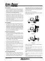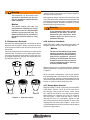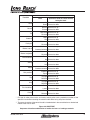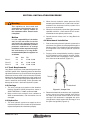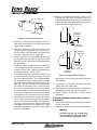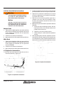
1
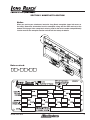
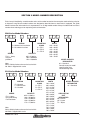
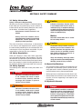
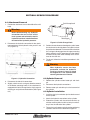
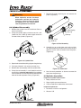
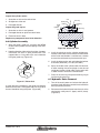
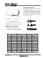
Installation, Maintenance and
Service Manual
FLN and FLS
45-009, REV. 10/13
1
TABLE OF CONTENTS
Section 1 Nameplate Location................... 3
Section 2 Model Number Description........ 4
Section 3 Safety Summary......................... 5
4.1 Truck Requirements............................... 10
4.2 Carriage................................................. 10
4.3 Hydraulics.............................................. 10
3.1 Safety Information.................................... 5
4.5 Fork Cylinder Anchor................................ 11
3.2 Safety Regulations................................... 5
4.6 Fork Installation Instructions.................. 12
3.3 Safety Symbols........................................ 5
4.7 Hydraulic Connections........................... 12
3.4 Operation Warnings................................. 5
3.5 Hydraulic Hazards .................................. 5
Section 5 Maintenance Schedule............. 13
Section 6 Service Procedure.................... 14
3.6 Electrical Hazards.................................... 6
6.1 Attachment Removal............................. 14
3.7 Maintenance Warnings............................ 6
6.2 Cylinder Removal.................................. 14
3.8 Training.................................................... 7
6.3 Cylinder Installation............................... 14
3.9 Labeling................................................... 7
6.4 Cylinder Disassembly............................ 15
3.10 Pre-Start Checks................................... 7
6.5 Cylinder Inspection........................... 15
3.11 Personnel Safety.................................... 7
6.6 Cylinder Assembly................................. 16
3.15 Operator’s Controls ............................... 8
6.7 Hydraulic Valve Removal....................... 16
3.16 Industry Standards................................ 8
6.8 Hydraulic Valve Installation.................... 17
3.17 Clamp Open Control.............................. 8
6.9 Torque Specifications............................. 17
Section 4 Installation Procedure.............. 10
45-009, REV. 10/13
2
SECTION 1 NAMEPLATE LOCATION
Notice
When you receive your attachment, locate the Long Reach nameplate (upper left corner on
the body). Record the information from the nameplate, along with the date received, at the
bottom of this page. If the nameplate is missing, look for the serial number stamped directly
into the metal at the nameplate location and consult the factory for details.
A
Date received:
-
45-009, REV. 10/13
-
3
SECTION 2 MODEL NUMBER DESCRIPTION
Each clamp is identified by a model number and a serial number located on the name plate attached to the unit prior
to shipment. Long Reach’s model numbers are designed to describe how an attachment is equipped. The guide
below illustrates the information that is represented in an 15-digit model number. Always include model and serial
number when ordering parts or requesting service information.
FLN Series Model Number:
F
L
N
C
1
0
0
DESIGN
4
MOUNTING
CLASS
C = Weld-on fork installation
D = No weld fork carriers
SERIES
B
5
0
1
WIDTH
325 = 32.50”
385 = 38.50”
415 = 41.50”
425 = 42.50”
505 = 50.50”
625 = 62.50”
785 = 78.50”
A = ITA II
B = ITA III
C = ITA IV
CAPACITY
FLN = Heavy
duty fork
positioner
1
055 = 5,500 lbs
100 = 10,000 lbs
150 = 15,000 lbs
MODEL SPECIFIC
DESIGNATOR
01 = Standard
Consult factory for model
specifics other than
standard designation
Note:
Weld = Weld cylinder anchor on the back of fork
No- Weld = Supplied fork carrier
FLS Series Model Number:
F
L
S
E
0
5
5
DESIGN
E = No-weld
F = Weld-on fork
G = No-weld
SERIES
FLS = Heavy
Duty Sideshifting
Fork Positioner
A
MOUNTING
CLASS
A = ITA II
B = ITA III
C = ITA IV
CAPACITY
055 = 5,500 lbs
100 = 10,000 lbs
120 = 12,000 lbs
150 = 15,000 lbs
175 = 17,500 lbs
Note:
Weld = Weld cylinder anchor on the back of fork
No-Weld = Supplied fork carrier
45-009, REV. 10/13
3
8
5
WIDTH
104 = 104.0”
385 = 38.50”
415 = 41.50”
425 = 42.50”
472 = 47.20”
475 = 47.50”
485 = 48.50”
505 = 50.50”
525 = 52.50”
625 = 62.50”
655 = 65.50”
715 = 71.50”
725 = 72.50”
745 = 74.50”
780 = 78.00”
785 = 78.50”
A
A
0
1
MODEL SPECIFIC
DESIGNATOR
01 = Standard
OEM CUSTOM
UNIT
DESIGNATOR
NS = Nissan
HY = Hyster
TY = Toyota
4
SECTION 3 SAFETY SUMMARY
3.1 Safety Information
Safety is Everyone’s Responsibility
Whether you are new on the job or a seasoned veteran,
these safety tips may prevent injury to you, to others, or
to the materials you are handling. Always be alert, watch
out for others, and follow these suggestions:
Attachments handle material, not
people.
Safety starts with common sense,
good judgement, properly maintained
equipment, careful operation, and
properly trained operators.
The safety instructions and warnings, as documented
in this manual and shipped with the machine, provide
the most reliable procedures for the safe operation and
maintenance of your Long Reach attachment. It’s your
responsibility to see that they are carried out.
3.2 Safety Regulations
Know your company’s safety rules. Some companies
have site-specific directions and procedures. The methods outlined in your operator's manual provide a basis for
safe operation of the machine. Because of special conditions, your company’s material handling procedures may
be somewhat different from those shown in this manual.
3.3 Safety Symbols
The following terms define the various precautions and
notices:
Danger
Indicates a hazardous situation which,
if not avoided, will result in death
or serious injury. Carefully read the
message that follows to prevent
serious injury or death.
Caution
Indicates a hazardous situation which,
if not avoided, could result in minor or
moderate injury, or equipment damage
or void the machine warranty. Carefully
read the message that follows to prevent
minor or moderate injury.
Notice
Describes information that is useful
but not safety related.
Caution
All possible safety hazards cannot be
foreseen so as to be included in this
manual. Therefore, the operator must
always be alert to possible hazards
that could endanger personnel or
damage to the equipment.
Obey the following warnings before
using your machine to avoid equipment
damage, personal injury or death.
3.4 Operation Warnings
• You must be trained to operate this equipment prior
to operation. Be extremely careful if you do not normally operate this machine. Reorient yourself to the
machine before starting, then proceed slowly.
• Always operate an attachment from the driver’s seat.
• Always lower the attachment if you need to leave the
lift truck. A lift truck supporting a load requires your
full attention.
3.5 Hydraulic Hazards
Warning
Danger
Indicates a hazardous situation which,
if not avoided, could result in death
or serious injury. Carefully read the
message that follows to prevent
serious injury or death.
Small hydraulic hose leaks are extremely
dangerous, and can inject hydraulic oil
under the skin, even through gloves.
Infection and gangrene are possible
when hydraulic oil penetrates the skin.
See a doctor immediately to prevent loss
of limb or death.
45-009, REV. 10/13
5
• Wear personal protective equipment, such as gloves
and safety glasses, whenever servicing or checking
a hydraulic system.
• Include attachments in a scheduled maintenance
and inspection program. Tailor inspection steps to
the attachment.
• Assume that all hydraulic hoses and components
are pressurized. Relieve all hydraulic pressure before
disconnecting any hydraulic line.
• Unless specified in service procedures, never attempt
maintenance or lubrication procedures while the machine is moving or the engine is running.
• Never try to stop or check for a hydraulic leak with any
part of your body; use a piece of cardboard to check
for hydraulic leaks.
• Always perform all maintenance and lubrication procedures with the machine on level ground, parked
away from traffic lanes.
Notice
Local laws and regulations may require
that additional safety measures be
taken.
3.6 Electrical Hazards
Warning
Remain at least 25 feet from high
voltage electrical wires. Failure to do
so may result in injury or death and
will damage equipment.
• All electrical cables and connectors must be in good
condition (free of corrosion, damage, etc). Use caution in wet weather to avoid danger from electrical
shock. Never attempt electrical testing or repair while
standing in water.
• Never rely on the hydraulic system to support any
part of the machine during maintenance or lubrication.
Never stand under a component that is supported
only by the hydraulics. Make sure it is resting on its
mechanical stops or appropriate safety stands.
• Use caution when working around hot fluids. Always
allow lubricating and hydraulic oils to cool before
draining. Burns can be severe.
• Use extreme caution when using compressed air to
blow parts dry. The pressure should not exceed 30
psi (208 kPa) at the nozzle. Never use compressed
air on yourself. Air pressure penetrating your skin
can be fatal.
• Engine exhaust fumes can cause death. If it is necessary to run the engine in an enclosed space, remove
the exhaust fumes from the area with an exhaust pipe
extension. Use ventilation fans and open shop doors
to provide adequate ventilation.
• Do not wear electrically conductive jewelry, clothing,
or other items while working on the electrical system.
3.7 Maintenance Warnings
Maintenance, lubrication and repair of this machine can
be dangerous unless performed properly. You must have
the necessary skills and information, proper tools and
equipment. Work in a method that is safe, correct, and
meets your company’s requirements.
• Do not attempt to make adjustments, or perform
maintenance or service unless you are authorized
and qualified to do so.
45-009, REV. 10/13
• Before disconnecting hydraulic lines, be sure to lower
all loads and relieve all hydraulic pressure. The load
could fall on you, or escaping hydraulic oil could cause
severe personal injury.
• Prevent personal injury or equipment damage by using a lifting device with a lifting capacity greater than
twice the weight of any equipment to be lifted.
6
3.8 Training
• Make sure all operators are trained in the fork and
attachment adaptation, operation, and use limitations.
Retrain an operator if a new attachment is added to
the forklift. Consult the operator’s manual for instructions on how to use the new equipment.
• Know the mechanical limitations of your forklift.
• Keep hands, feet, long hair and clothing away from
power-driven parts. Do not wear loose fitting clothing
or jewelry while performing maintenance and lubrication in these areas.
• Never jump on or off the machine.
• Never stand on top of material being raised, lowered,
or transported. (Figure 3-1)
• Modifications or additions that affect capacity or safe
operation must have prior written approval from the
forklift truck manufacturer. Capacity, operation, and
maintenance instruction plates, tags, or decals shall
be changed accordingly.
• Never use free rigging for a below-the-forks lift. It could
affect the capacity and safe operation of a lift truck.
3.9 Labeling
• Change capacity, operation, and maintenance instruction plates, tags, or decals when a forklift truck is
equipped with an attachment. If the truck is equipped
with front-end attachments other than factory installed
attachments, truck must be marked to identify the
attachments and show the approximate weight of
the truck and attachment combination at maximum
elevation with load laterally centered.
Figure 3-1
3.10 Pre-start Checks
• Check your equipment before you operate it. If anything looks wrong, unusual or different, report it before
using the attachment.
Figure 3-2
• Do not operate this machine if you know of malfunctions, missing parts, and/or mis-adjustments. These
situations can cause or contribute to an accident or
damage to the machine. Stop the machine immediately if problems arise after starting.
• Check to make sure the attachment on your truck is
the same as on the truck capacity plate.
• Check for hydraulic leaks and cracked hoses or fittings. Check the hydraulic oil level in the lift truck
hydraulic reservoir.
• All electrical cables and connectors must be in good
condition. Use caution in wet weather to avoid danger
from electrical shock.
• Always check the attachment for proper fit and engagement of the truck carriage.
3.11 Personnel Safety
• When removing or installing dismountable attachments always keep hands and feet free from
dangerous positions or pinch points. Never leave a
dismounted attachment in a dangerous position.
45-009, REV. 10/13
Figure 3-3
• Never use the attachment or its load to support a
man-carrying device.
• Never allow anyone under a load or under the carriage. (Figure 3-2)
• Never stand in front of or beside an attachment that
is being operated. Never allow another person to approach an attachment that is being operated. (Figure
3-3)
• Never leave an attachment or load in an elevated
position.
• Never reach through the mast of the truck. Keep all
parts of the body within the driver’s compartment.
7
Warning
The capacity of the truck and
attachment combined may be less
than the attachment capacity. Consult
truck nameplate!
Notice
The dealer and/or the user are
responsible for installing any valving
required to meet the recommended
hydraulic pressures and flow. The
required valving can be furnished by
the dealer, the truck factory or Long
Reach.
Lifting speed is controlled by the speed of the engine
and the position of the control lever. Engine speed has
no effect on lowering speed.
Before going on the job, shift the truck control levers one
way and then the other to determine which direction the
attachment moves when the levers are shifted. Make sure
the attachment moves smoothly throughout its travel,
without binding or pinching hoses.
Warning
If the attachment does NOT operate
smoothly, do not take it on the job.
Check with your supervisor about
needed repairs to avoid injury or
equipment damage.
3.15 Operator’s Controls
3.16 Industry Standards
Some lift trucks are equipped with a single lever to control
both hoist and tilt functions, others have separate levers
for each function. Refer to your lift truck manual for more
information.
ANSI/ITSDF B56.1-2009 is the published sequence and
direction standard for lever- and hand-type controls.
For clarity, the direction of arm movement is shown on the
control handle. To move the arms in the direction shown,
pull the handle towards the operator. To move the arms
in the opposite direction, the push the handle away from
the operator. (Figure 3-5)
Notice
The chart on the following page shows
industry standards. Your equipment
may be different. If you do not routinely
operate this equipment, refresher
training is recommended. You must
reacquaint yourself with this manual
and the equipment before starting,
and then proceed slowly.
Special controls such as automatic devices should be
identified, preferably according to the recommendations
in Figure 6.
Clamp
Fork position
When a function is controlled by a pair of push buttons,
they should operate in the same sense as the lever controls. For example, pushing a button located to the rear
(relative to the operator’s position) should serve the same
function as moving a control lever to the rear.
3.17 Clamp Open Control
Push/pull
Rotate
Sideshift
Figure 3-5 Operator controls
45-009, REV. 10/13
Effective October 7, 2010, a new safety standard (ANSI/
ITSDF B56.1, Section 7.25.7) for all lift trucks with a
load bearing clamp (paper roll clamp, carton clamp,
etc.) requires the driver to make two distinct motions
before opening or releasing the clamp. For example,
you must press a switch and then move a lever to
unclamp the load. This requirement applies to new
and used attachments being mounted on new trucks
shipping from the factory after October 7, 2010, and is
a recommended feature to be installed on dealer orders
and existing applications.
8
Direction of motion
Function
Load
Hoist
Reach
Tilt
Sideshift
Push-pull
Rotate, lateral
Rotate, longitude
Load stabilizer
Swing
Slope
Fork position
Trip
Grip
Truck stabilizer
Clamp
Operator's hand on control handle,
facing the load*
Up Rearward or up
Down Forward or down
Retract Rearward or up**
Extend Forward or down
Rearward Rearward or up**
Forward Forward or down
Right Rearward or up
Left Forward or down
Rearward Rearward or up**
Forward Forward or down
Clockwise Rearward or up
Counterclockwise Forward or down
Rearward Rearward or up
Forward Forward or down
Down Rearward or up
Up Forward or down
Right Rearward or up
Left Forward or down
Clockwise Rearward or up
Counterclockwise Forward or down
Together Rearward or up
Apart Forward or down
Engage Rearward or up
Release Forward or down
Engage Rearward or up
Release Forward or down
Raise Rearward or up
Lower Forward or down
Clamp Rearward or up
Release Forward or down
* For high lift order picker trucks and center control pallet trucks, predominant motion of the
operator's hand when actuating the control handle while facing away from the load.
** The sense of rotation of the control handle is intended to be in the same direction as the desired
motion of the mast or load.
Figure 3-6 ANSI/ITSDF
Sequence of location and direction of motion for lever- or hand-type controls
45-009, REV. 10/13
9
SECTION 4 INSTALLATION PROCEDURE
Warning
The capacity of the truck and
attachment combination may be
less than the capacity shown on
the attachment alone. Consult truck
nameplate!
Notice
it is the responsibility of the dealer
and / or the user either to furnish
and install the required valving to
meet the recommended hydraulic
pressures and flow or to arrange
installation of the required valving at
the truck factory or at Long Reach.
recommended hydraulic supplies are
as follows:
Min. Max.PSI
Class II
3.2
4.1
2,200 - 3,000
Class III
2.9
6.4
2,200 - 3,000
Class IV
4.0
12.0
2,200 - 3,000
2. When the truck hydraulic system pressures (PSI)
exceeds specified maximum, a relief valve is recommended in the attachment auxiliary system of the
truck or on the attachment.
3. When the truck hydraulic system flow (gpm) exceeds
specified maximum, a flow control valve is recommended to ensure optimal performance.
4. Consult the truck factory and / or Long Reach for
guidance.
4.4 Attachment Installation
1. Prior to connecting the truck hydraulic system to the
attachment, the system must be purged through the
filtration system. This will eliminate any contamination
that might exist in the auxiliary hydraulic system of
the truck.
2. Purging can be accomplished by installing a jumper
line and operating each hydraulic function (clamp,
rotate and side shift if equipped) in each direction
for a minimum of 30 seconds. (Figure 4-1)
4.1 Truck Requirements
Long Reach attachments have been designed to operate within specific limits. Operating pressures above the
stipulated maximum may cause structural damage to the
attachment and may result in loss of warranty. Hydraulic
flow less than the recommended rates, or the use of small
I.D. hoses may reduce operating speed. Higher flow can
result in excessive heat buildup, erratic operation and
damage to the truck / attachment hydraulic system.
4.2 Carriage
1. The truck carriage must conform to the American
National Standard (ANSI) dimensions shown in
ANSI/ITSDF B56.11.4-2005, reaffirmed 2000.
2. Make sure the truck carriage is clean, conforms to
ANSI recommendations, and the notches are not
damaged.
4.3 Hydraulics
1. The truck hydraulic system must supply to the attachment hydraulic oil that meets the specifications
required to operate the attachment properly.
45-009, REV. 10/13
To truck
To attachment
Figure 4-1, Jumper Line
3. Remove the lower bolt-on retainers and, if applicable,
make a note of any factory installed shims. Shims
are used to space the retainer closer to the truck
carriage. if the attachment is equipped with quick
change hooks, simply remove the retaining pin and
the quick change hook (Figure 4-2).
10
Quick change hook
10. Weld on the supplemental locking lug that is supplied with the attachment, (two pieces of 1/2 x 1/2 x
2.00 steel included with the attachment) with either
E-6011 or E-6013 welding rod, or equivalent, on each
side of the truck carriage. (Figure 4-3).
Maximum
Clearance
3/32”
Retaining pin
Figure 4-2, Quick Change Hook
4. Center the truck behind the attachment and drive
toward the attachment with the mast tilted forward
approximately 4 degrees.
Shim(s)
as Required
5. Line up the locking lug (under the mid plate, if applicable) with the appropriate notch on the truck’s
carriage. Check that the bronze side shifting wear
strips are in the proper place, if applicable.
Maximum
Clearance
1/32”
6. Slowly raise the truck carriage completely to engage
the top hooks with the truck carriage. Tilt carriage
back until the unit is against the carriage bottom fork
bar (0 degrees).
Maximum
Clearance
1/8”
7. Inspect for proper engagement of the locking lug
in the corresponding notch of the truck’s carriage.
Inspect any wear strips, if applicable, to ensure they
are properly aligned in the top hooks.
8. To install the lower roller assemblies (side-shift) use
a suitable device to move the attachment away from
the carriage approximately 2”. Place a block between
the attachment and the carriage to hold it in position.
Install the rollers into the heel plate pockets on the
lower right and left hand sides of the attachment.
The rollers do not need to face a particular direction. Gently move the bottom of the attachment out
to remove the block. Lower the attachment down the
face of the carriage. Ensure that the rollers remained
in the pockets and are in contact with the carriage.
9. Install the bolt-on lower hooks. Inspect clearance to
the carriage on lower hooks. Adjust the lower hooks
for a maximum clearance of 3/32” (see Figure 4-4).
On Class II and Class lll units, tighten the 3/8” bolts
to 33 ft-lbs. On Class lV units tighten the 1/2” bolts
to 77 ft-lbs. On units using 9/16” UNC bolts, tighten
the bolts to 112 ft-lbs.
Shim(s)
as Required
(If Over Consult Factory)
Figure 4-3, Lower Hook Clearance
Locking lugs are not required for side shifting units
with midplates.
11. If quick hooks are installed, place the retaining pin
through the quick change hook.
12. Apply grease to bronze top hooks through fittings
and spread on entire slide area of mid plate.
13. Check all fittings, connections and bolts for any
interference.
4.5 Fork Cylinder Anchor (Some FLS and
FLN Models)
1. Refer to documentation that came with your machine
for fork lug location.
2. Make sure cylinder is parallel to carriage weldment.
Notice
Cylinder anchors are shipped with
new attachments. Always protect
cylinder rod from weld spatter, etc.
45-009, REV. 10/13
11
4.6 Fork Installation Instructions
Warning
Over-torquing the installation hardware
can result in a bent positioner side
plate and/or broken set screw(s).
Notice
Cylinder rod clevis pins must be
removed to slide the fork postioners
into allignment with the installation
notches on the fork bottom bar.
Narrow Fork
1. Tighten the included long Allen set screws until they
touch the forks. Without further tightening of the set
screws, tighten the installation jam nut against the
carrier to 41 ft-lbs.
2. Check the set screws for interference.
3. Appy grease to face of the upper and lower fork bars.
Wide Fork
1. Tighten the included short Allen set screws until they
touch the forks. Without further tightening of the set
screws, tighten the installation jam nut against the
carrier to 41 ft-lbs.
2. Inspect installation to ensure hoses are not kinked or
pinched between the truck carriage and attachment.
3. Operate the attachment continuously for several
minutes to determine that all hydraulic connections
are secure with no leaks.
4. With the mast in the vertical position, open the attachment arms fully. After this procedure, check
that the truck’s hydraulic reservoir oil level is at the
recommended level.
5. Before placing the attachment in operation check the
following:
a. Inspect all hoses and fittings for leaks and rout
ing clearance. Be sure to include clearance of
jumper hoses to the mast.
b. Check the valve and cylinder for leaks.
c. Check cotter pins at each end of the cylinder for
security.
6. After completing the installation, operate the attachment without a load for several cycles to remove any
air in the hydraulic system. Test the attachment with a
load to make sure the attachment operates correctly.
2. Check the set screws for interference.
3. Appy grease to face of the upper and lower fork bars.
4.7 Hydraulic Connections
1. Install the lines from the truck’s hydraulics to the attachment hydraulics. (Figure 4-4)
Figure 4-5, Hydraulic Schematic
Figure 4-4, Hydraulic Connection
45-009, REV. 10/13
12
SECTION 5 MAINTENANCE SCHEDULE
Daily:
Notes:
1. Visually inspect all hoses, fittings, cylinders, and
valves for signs of hydraulic leaks.
2. Visually inspect for external damage or cracks.
3. Check lower hooks for proper clearance. Maximum
clearance is 3/16 of an inch.
4. If the attachment is equipped with Quick Change
Hooks check the slide plate latch for engagement.
40 Hour Maintenance:
1. On the bronze top hooks check grease fittings to
ensure that they are clean and properly working.
Apply grease if needed.
2. Appy grease to face of the upper and lower fork bars.
100 Hour Maintenance:
1. Complete the above daily checks.
2. Check all hoses and fittings for wear or damage.
Inspect for hydraulic leaks.
3. Check for loose or missing bolts.
4. Check wear on the bronze top hooks. Bronze top
hooks should be replaced when the clearance between the bottom hook and the carriage is greater
than 3/16 of an inch, or when wear on the mid plate
becomes visible.
250 Hour Maintenance:
1. Check the torque on all bolts securing the bronze
top hooks, upper retainers and lower hooks per
the torque specification charts in Section 6 of this
manual.
Recommended Grease:
Mobile XHP222 Special or similar quality EP-2 with
Lithium Complex Base.
45-009, REV. 10/13
13
SECTION 6 SERVICE PROCEDURE
6.1 Attachment Removal
Quick change hook
1. Position the attachment arms to the width of the unit’s
body.
Warning
Before disconnecting any hydraulic
connections be sure to turn off the
truck’s power and activate the truck’s
hydraulic functions in both directions
to bleed off the hydraulic pressure.
2. Disconnect the hydraulic connection for the attachment positioning at the hydraulic valve, ports V1 and
V2. (Figure 6-1)
Retaining pin
Figure 6-2, Quick Change Hook
5. Position the attachment on the edge of a pallet. Lower
the attachment so that the lower carriage bar misses
the pallet when lowered. Tilt the mast forward to allow
the carriage to disengage from the upper mounting
hooks and back away. If lowering onto a floor, blocks
of wood can be place under the body of the attachment to raise the rear.
6. To reinstall, follow the installation procedure in this
manual.
Warning
When hydraulic service has been
performed, activate the hydraulic
functions several times to bleed
out trapped air in the system before
returning attachment to service.
Figure 6-1, Hydraulic Connection
3. Disconnect the side shift connections.
4. Slightly raise the truck carriage to allow the removal
of the bottom mounting hooks. If the attachment is
equipped with Quick Change Hooks, simply remove
retaining pin and pull lower hooks down. (See Figure
6-2)
6.2 Cylinder Removal
1. Remove the cylinder rod end cotter pin and clevis
pin.
2. Disconnect the hydraulic connections.
3. Remove cotter pin and clevis pin at the base end of
the cylinder.
6.3 Cylinder Installation
1. Install the clevis pin and cotter pin into the base end
of the cylinder.
2. Attach the hydraulic connections to the cylinder.
3. Extend the cylinder until the rod end hole lines up
with the mounting hole. Install the clevis pin and cotter pin into the rod end of the cylinder.
4. Turn on the truck’s power and activate the positioning
cylinders several times to bleed out trapped air.
45-009, REV. 10/13
14
7. Remove the piston retaining nut and remove the
piston. (Figure 6-5)
Warning
When hydraulic service has been
performed, activate the hydraulic
functions several times to bleed
out trapped air in the system before
returning attachment to service.
6.4 Cylinder Disassembly
1. Remove the cylinder from the attachment. See removal instructions.
Retaining ring
Lock ring
2. Clamp the cylinder lightly at the base end in a soft
jawed vise. Use a block or other support under the
rod end of the cylinder. (Figure 6-3)
Gland cap
Piston
Piston nut
Figure 6-5, Rod Assembly
8. Carefully pry up on the piston seals using a blunt
tip screw driver being careful not to scratch the seal
grooves. Cut the seals to remove from the piston.
(Figure 6-6)
A
Figure 6-3, Cylinder Vise
3. Spread and remove the retaining ring from the gland cap.
4. Push gland inward 1 inch and pry out lock ring.
5. Remove the rod assembly from the cylinder tube.
6. Clamp the rod assembly in a soft jawed vise on the
wrench flats, not on the rod surface. If the rod does
not have wrench flats use two pieces of wood on both
sides of the rod to prevent scaring. (Figure 6-4)
Figure 6-6, Piston Seal
9. Use the same procedure as above to remove the
seals from the gland cap.
6.5 Cylinder Inspection
Inspect the cylinder tube bore for:
1. Deep scratches or nicks.
2. Signs of galling or excessive wear.
3. Out-of-roundness or deformities of the barrel.
Inspect the piston for:
1. Scratches or nicks on seal grooves.
2. Wear on O.D.
Figure 6-4, Cylinder Shaft
45-009, REV. 10/13
15
Inspect the cylinder rod for:
1. Scratches or nicks on the rod surface.
2. Straightness of the rod.
3. Damaged threads.
Inspect the gland cap for:
1. Scratches or nicks in seal grooves.
Gland
cap
Cylinder
rod
Seal
Backup ring
O-Ring
Lock ring
Retaining
ring
Wiper ring
2. Damaged threads or spanner wrench holes.
3. Excessive wear in bore.
Replace any component found to be defective.
6.6 Cylinder Assembly
1. Spray the piston, gland cap, and seals with WD40
or other similar product to ease slipping of the seals
in place.
2. Note the direction of the seal on the piston. Improper
installation will result in poor performance. The
cupped side or O-ring side of the seal should be
facing the gland cap. (Figure 6-7)
Figure 6-8, Gland Cap Seal
4. Install the gland cap on the cylinder rod being extremely careful not to cut the rod seal on the threads
of the rod or rod shoulder. If available use a sleeve
to cover the rod threads or plastic electrical tape.
5. Install the piston on the rod and tighten the locknut
to 90 ft-lbs (0.56 UNF), 22 ft-lbs (0.75 UNF).
6. Spray the inside of the cylinder tube with lubricant
to ease inserting the rod and piston. Insert the rod
and piston into the cylinder tube. Tap the rod in with
a rubber mallet if resistance is encountered.
7. Press on the lock ring and spread retaining ring to
install onto the gland cap.
6.7 Hydraulic Valve Removal
Figure 6-7, Piston Seal
3. Install the seals and wipers in the gland cap. Note the
direction of the seals. The cupped side or O-ring side of
the seal should be facing the piston. (Figure 6-8)
45-009, REV. 10/13
1. Turn off the truck’s power and activate the hydraulic
functions in both directions several times to relief the
built up hydraulic pressure.
2. Disconnect the hydraulic hoses from the truck at the
attachments valve ports V1 (open) and V2 (close).
(Figure 6-9)
16
6.9 Torque Specifications
The following torque values are to be used on all fasteners unless otherwise specified.
Lubricated refers to fasteners in the “As Received” condition, which is normally a light preservative oil coating on
unplated fasteners and no oil coating on plated fasteners. No special steps are taken to add further lubrication
prior to assembly. Dry refers to parts that have been
degreased, both mating parts.
Figure 6-9, Hydraulic Hoses
Grade 5
3. Disconnect the hydraulic hoses at the valve ports C1
and C2.
4. Remove the valve mounting bolts and remove valve.
6.8 Hydraulic Valve Installation
Grade 8
1. Reassembly in the reverse order above.
2. Turn on the truck’s power and activate the hydraulic
functions serveral times to bleed out trapped air.
GRADE 8 COURSE THREAD
Bolt Size
Lubricated Torque
GRADE 5 COURSE THREAD
Bolt Size
Lubricated Torque
Socket Head Capscrew
SOCKET HEAD COURSE THREAD
Capscrew Size
Lubricated Torque
1/4"
129 in-lbs
1/4"
91 in-lbs
1/4"
150 in-lbs
5/16"
23 ft-lbs
5/16"
16 ft-lbs
5/16"
26 ft-lbs
3/8"
40
3/8"
28
3/8"
46
7/16"
63
7/16"
45
7/16"
74
1/2"
96
1/2"
68
1/2"
115
9/16"
140
9/16"
98
9/16"
160
5/8"
195
5/8"
140
5/8"
215
3/4"
340
3/4"
240
3/4"
385
7/8"
550
7/8"
390
7/8"
615
1"
820
1"
580
1"
920
1-1/8"
1,160
1-1/8"
715
1-1/8"
1,305
1-1/4"
1,640
1-1/4"
1,010
1-1/4"
1,840
1-3/8"
2,150
1-3/8"
1,330
1-3/8"
2,415
1-1/2"
2,850
1-1/2"
1,760
1-1/2"
3,205
Figure 6-10 Torque Chart
45-009, REV. 10/13
17