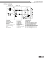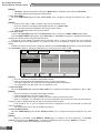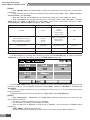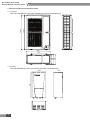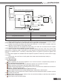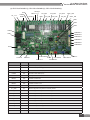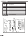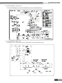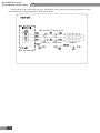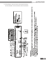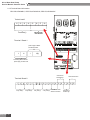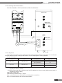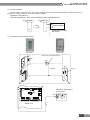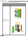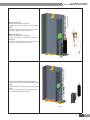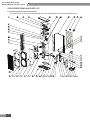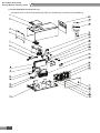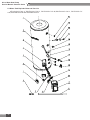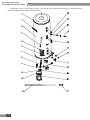
1
AIR TO WATER HEAT PUMP SERVICE MANUAL Versati II T1/R410A/50Hz (GC201308- ) CONTENTS PRODUCT ������������������������������������������������������������������������������������������������������ 2 1 MODELS LIST ������������������������������������������������������������������������������������������������������������ 2 1.1 Main Unit���������������������������������������������������������������������������������������������������������������������������������������� 2 1.2 Water Tank������������������������������������������������������������������������������������������������������������������������������������� 2 2 NOMENCLATURE������������������������������������������������������������������������������������������������������� 2 2.1 Main Unit���������������������������������������������������������������������������������������������������������������������������������������� 2 2.2 Water Tank������������������������������������������������������������������������������������������������������������������������������������� 3 3 FUNCTION ����������������������������������������������������������������������������������������������������������������� 3 3.1 Cooling ������������������������������������������������������������������������������������������������������������������������������������������ 3 3.2 Heating ������������������������������������������������������������������������������������������������������������������������������������������ 3 3.3 Water Heating�������������������������������������������������������������������������������������������������������������������������������� 3 3.4 Cooling +Water Heating���������������������������������������������������������������������������������������������������������������� 3 3.5 Heating+ Water Heating���������������������������������������������������������������������������������������������������������������� 3 3.6 Emergency Mode�������������������������������������������������������������������������������������������������������������������������� 3 3.7 Quick Water Heating��������������������������������������������������������������������������������������������������������������������� 4 3.8 Holiday Mode��������������������������������������������������������������������������������������������������������������������������������� 4 3.9 Forced Operation Mode ��������������������������������������������������������������������������������������������������������������� 4 3.10 Silent Mode���������������������������������������������������������������������������������������������������������������������������������� 4 3.11 Disinfection Mode����������������������������������������������������������������������������������������������������������������������� 4 3.12 Weather-dependent Heating Mode�������������������������������������������������������������������������������������������� 4 4 PRODUCT DATA��������������������������������������������������������������������������������������������������������� 5 4.1 Product Data at Rated Condition ������������������������������������������������������������������������������������������������ 5 4.2 Operation Range��������������������������������������������������������������������������������������������������������������������������� 7 4.3 Electrical Data ������������������������������������������������������������������������������������������������������������������������������ 8 5 PIPING DIAGRAM������������������������������������������������������������������������������������������������������� 9 UNITS CONTROL������������������������������������������������������������������������������������������11 1 OPERATION FLOWCHART�������������������������������������������������������������������������������������� 11 2 MAIN LOGIC������������������������������������������������������������������������������������������������������������� 12 2.1 Defrosting Mode�������������������������������������������������������������������������������������������������������������������������� 12 2.2 Water-side Auto Anti-freezing in Winter ����������������������������������������������������������������������������������� 12 2.3 Control of Heating Tape on Chassis������������������������������������������������������������������������������������������ 12 2.4 Control of Fan������������������������������������������������������������������������������������������������������������������������������ 12 2.5 Control of Compressor��������������������������������������������������������������������������������������������������������������� 12 2.6 Control of Electric Expansion Valve ���������������������������������������������������������������������������������������� 12 3 WIRED CONTROLLER��������������������������������������������������������������������������������������������� 13 3.1 Dimension������������������������������������������������������������������������������������������������������������������������������������ 13 3.2 Function��������������������������������������������������������������������������������������������������������������������������������������� 13 3.3 Operation Instruction������������������������������������������������������������������������������������������������������������������ 15 3.4 Precautions���������������������������������������������������������������������������������������������������������������������������������� 33 4 CONTROL WIRING DESIGN������������������������������������������������������������������������������������ 33 INSTALLATION��������������������������������������������������������������������������������������������� 35 1 INSTALLATION OF UNITS��������������������������������������������������������������������������������������� 35 1.1 Installation Positions������������������������������������������������������������������������������������������������������������������ 35 1.2 Matters Need Attention��������������������������������������������������������������������������������������������������������������� 35 1.3 Dimension Data and Installation Guide������������������������������������������������������������������������������������ 36 1.4 Installation Clearance Data�������������������������������������������������������������������������������������������������������� 42 1.5 The method of calculating the charging pressure of expansion vessel needed to be adjusted is as follows.���������������������������������������������������������������������������������������������������������������������� 43 1.6 Connection of Pipeline �������������������������������������������������������������������������������������������������������������� 45 2 ELECTRIC WIRING WORK�������������������������������������������������������������������������������������� 47 2.1 Wiring Principle��������������������������������������������������������������������������������������������������������������������������� 47 2.2 PCB Outline��������������������������������������������������������������������������������������������������������������������������������� 48 2.3 Electric Wiring Design ��������������������������������������������������������������������������������������������������������������� 50 UNITS MAINTENANCE ������������������������������������������������������������������������������� 60 1 ERROR CODE LIST ������������������������������������������������������������������������������������������������� 60 2 FLOW CHART OF TROUBLESHOOTING �������������������������������������������������������������� 64 3 DIAGNOSIS OF DRIVING����������������������������������������������������������������������������������������� 68 3.1 Diagnosis Flowchart of Driving of Single-phase Unit and Three-phase Unit������������������������ 68 4 DISASSEMBLY AND ASSEMBLY PROCEDURE OF MAIN PARTS ���������������������� 72 5 EXPLODED VIEWS AND PART LIST ���������������������������������������������������������������������� 82 5.1 Outdoor Exploded View and Part List��������������������������������������������������������������������������������������� 82 5.2 Indoor Exploded View and Part List������������������������������������������������������������������������������������������ 84 5.3 Water Tank Exploded View and Part List���������������������������������������������������������������������������������� 86 Air to Water Heat Pump Service Manual- Versati II Series PRODUCT 1 PRODUCT Air to Water Heat Pump Service Manual- Versati II Series PRODUCT 1 MODELS LIST 1.1 Main Unit Nominal Capacity Model Model Name Product Code GRS-CQ12Pd/ NaB-K(I) GRS-CQ12Pd/ NaB-K(O) GRS-CQ14Pd/ NaB-K(I) GRS-CQ14Pd/ NaB-K(O) GRS-CQ16Pd/ NaB-K(I) GRS-CQ16Pd/ NaB-K(O) GRS-CQ12Pd/ NaB-K GRS-CQ14Pd/ NaB-K GRS-CQ16Pd/ NaB-K ER010N1130 ER010W1130 ER010N1140 ER010W1140 ER010N1150 ER010W1150 kW Refrigerant Power Supply Appearance V,Ph,Hz Outdoor Unit Indoor Unit 12.5 13.5 R410A 230,1,50 15.5 Note:1Ton =12000Btu/h = 3.517kW 1.2 Water Tank Model Product Code Nominal Cubage(L) SXVD200LCJ/A-K ER20000160 200 SXVD200LCJ/A-M ER20000240 200 SXVD300LCJ/A-K ER20000180 300 SXVD300LCJ/A-M ER20000250 300 SXVD200LCJ2/A-K ER20000170 200 SXVD200LCJ2/A-M ER20000260 200 SXVD300LCJ2/A-K ER20000190 300 SXVD300LCJ2/A-M ER20000270 300 Appearance 2 NOMENCLATURE 2.1 Main Unit PRODUCT 2 G RS 1 2 - C Q 16 Pd 3 4 5 6 / Na B 7 8 - K (I) 9 10 NO. Description Options 1 GREE Air to water heat pump - 2 Heat Pump Water Heater - 3 Heating Mode Circulating 4 Multi Heat pump - 5 Nominal Heating capacity 16=16 kW 6 DC Inverter - 7 Refrigerant Type Na-R410A 8 Design Serial Number A,B,C…... 9 Power Supply K=220-240V,~,50Hz; M=380-415V,3N~,50Hz; H=380V,3N~,60Hz 10 Indoor Unit I-Indoor unit, O-outdoor unit Air to Water Heat Pump Service Manual- Versati II Series 2.2 Water Tank SX V D 200 L C J2 1 2 3 4 5 6 7 / A - 8 K 9 NO. Description Options 1 Tank Used in Heat Pump / 2 Heat Pump Water Tank for GMV Units / 3 Electric Heater / 4 Volume of Tank / 5 Stand / 6 Pressure-Resistant / 7 Static Heating with Dual Coiled Pipe J=Static Heating with single Coiled Pipe ; J2=Static Heating with Dual Coiled Pipe 8 Design Sequence Number 9 Power Supply K=220-240V,~,50Hz; M=380-415V,3N~,50Hz; H=380V,3N~,60Hz 3 FUNCTION 3.1 Cooling In cooling mode: the refrigerant is condensed in the outdoor unit and evaporated in the indoor unit. Via the heat exchange with water in the indoor unit, the temperature of water decreases and it releases heat while the refrigerant absorbs heat and evaporates. With the help of wired controller, the outflow temperature can meet the user’s requirement. Through the control of valve, the low-temperature water in the system is connected with indoor fan coil and underground pipe, and exchanges heat with the indoor air so that the indoor temperature decreases to the required range. 3.2 Heating In heating mode: the refrigerant evaporates in the outdoor unit and is condensed in the indoor unit. Via the heat exchange with water in the indoor unit, the water absorbs heat and its temperature increases while the refrigerant releases heat and is condensed. With the help of wired controller, the outflow temperature can meet the user’s requirement. Through the control of valve, the high-temperature water in the system is connected with indoor fan coil and underground pipe, and exchanges heat with the indoor air so that the indoor temperature increases to the required range; 3.3 Water Heating In water heating mode: the refrigerant evaporates in the outdoor unit and is condensed in the indoor unit. Via the heat exchange with water in the indoor unit, the water absorbs heat and its temperature increases while the refrigerant releases heat and is condensed. With the help of wired controller, the outflow temperature can meet the user’s requirement. Through the control of valve, the high-temperature water in the system is connected with the coil pipe of bearing water tank, and exchanges heat with the water in the water tank so that the temperature of water tank increases to the required range. 3.4 Cooling +Water Heating When cooling mode exists together with the water heating mode, the user can set the priority of these two modes based on the needs. The default priority is heat pump. That is under the default setting, if cooling mode exists together with the water heating mode, the heat pump gives priority to cooling. In that case, water heating can only realized with e-heater of the water tank. Inversely, the heat pump gives priority to water heating and switches to cooling after finishing water heating. 3.5 Heating+ Water Heating When heating mode exists together with the water heating mode, the user can set the priority of these two modes based on the needs. The default priority is heat pump. That is under the default setting, if heating mode exists together with the water heating mode, the heat pump gives priority to heating. In that case, water heating can only realized with e-heater of the water tank. Inversely, the heat pump gives priority to water heating and switches to heating after finishing water heating. 3.6 Emergency Mode Emergency mode: this mode is only available for heating and water heating. When the outdoor unit stops due to malfunction, it will enter the corresponding emergency mode; as to heating mode, after entering the emergency mode, heating can only be realized through e-heater of the indoor unit. When the setting outflow temperature or indoor temperature is reached, the e-heater of indoor unit will stop running; as to water heating mode, the e-heater of indoor unit stops while the e-heater of water tank runs. When the setting temperature or 3 PRODUCT Air to Water Heat Pump Service Manual- Versati II Series water tank is reached, the e-heater will stop running. 3.7 Quick Water Heating In quick water heating mode, the unit runs according to the water heating control of heat pump and the e-heater of water tank runs at the same time. 3.8 Holiday Mode This mode is only available for heating mode. This mode is set to keep indoor temperature or outflow temperature in a certain range, so as to prevent water system of the unit from freezing or protect certain indoor articles from freezing damage. (This mode requires installing indoor temperature sensor). When the outdoor unit stops due to malfunction, the two e-heaters of the unit will run. 3.9 Forced Operation Mode This mode is only used for refrigerant recovery and debugging of the unit. 3.10 Silent Mode Silent mode is available in cooling, heating and water heating mode. In silent mode, the outdoor unit will reduce the running noise via automatic control. 3.11 Disinfection Mode In this mode, the water heating system can be disinfected. When starting up the disinfection function and setting corresponding time to meet the requirement of disinfection mode, the function will start. After the setting temperature is reached, this mode will terminate. 3.12 Weather-dependent Heating Mode This mode is only available for space heating. In weather-dependent heating mode, the indoor temperature is detected and controlled automatically. 3.13 Floor Commissioning This function is intended to preheat the floor periodically for the initial use. 3.14 Air Removal of the Water System This function is intended to replenish water and remove air in the water system to make the equipment run at the stabilized water pressure. PRODUCT 4 Air to Water Heat Pump Service Manual- Versati II Series 4 PRODUCT DATA 4.1 Product Data at Rated Condition Due to continues improvement on the products, the specifications listed above are subject to change without notice, and the ones on the products nameplate should be referred to as final. 4.1.1 Outdoor Unit Capacity*1 Power Input*1 Model GRS-CQ12Pd/NaB-K(O) GRS-CQ14Pd/NaB-K(O) GRS-CQ16Pd/NaB-K(O) Product Code ER010W1130 ER010W1140 ER010W1150 Cooling(floor cooling) kW 12.5 13.5 14.5 Heating(floor heating) kW 12.5 13.5 15.5 Cooling(floor cooling) kW 3.57 4.09 4.53 Heating(floor heating) kW 2.81 3.07 3.78 W/W 3.5/4.45 3.3/4.4 3.2/4.1 Cooling(for Fan coil) kW 9.5 10 10.5 Heating(Fan coil or Radiator) kW 11 12 14 Cooling(for Fan coil) kW 3.39 3.57 3.96 Heating(Fan coil or Radiator) kW 3.14 3.48 4 W/W 2.8/3.5 2.8/3.45 2.65/3.5 kg 3.2 3.2 3.2 40~80 40~80 40~80 EER/COP* Capacity*2 Power Input*2 EER/COP* 1 2 Refrigerant charge volume Sanitary water Temperature Sound Pressure Level Connecting pipe Dimensions (W×D×H) cooling dB(A) 55 55 57 heating dB(A) 57 57 58 Gas inch(mm) φ5/8(15.9) φ5/8(15.9) φ5/8(15.9) Liquid inch(mm) φ3/8(9.52) φ3/8(9.52) φ3/8(9.52) Outline mm 900×412×1345 900×412×1345 900×412×1345 Packaged mm 998×458×1515 998×458×1515 998×458×1515 kg 106/118 106/118 106/118 Net weight/Gross weight Notes: 1 Capacities and power inputs are based on the following conditions: a.Cooling conditions Indoor Water Temperature 23°C/18°C; Outdoor Air Temperature 35°CDB/24°CWB b.Heating conditions Indoor Water Temperature 30°C/35°C; Outdoor Air Temperature 7°CDB/6°CWB c.Standard piping length 7.5m 2 Capacities and power inputs are based on the following conditions: a.Cooling conditions Indoor Water Temperature 12°C/7°C; Outdoor Air Temperature 35°CDB/24°CWB b.Heating conditions Indoor Water Temperature 40°C/45°C; Outdoor Air Temperature 7°CDB/6°CWB c.Standard piping length 7.5m 5 PRODUCT Air to Water Heat Pump Service Manual- Versati II Series 4.1.2 Indoor Unit Model GRS-CQ12Pd/NaB-K(I) GRS-CQ14Pd/NaB-KI) GRS-CQ16Pd/NaB-K(I) Product Code ER010N1130 ER010N1140 ER010N1150 V/Ph/Hz 1/220-240/50 1/220-240/50 1/220-240/50 W Power Supply Norminal input Leaving water temperature Pump Electric Heater 6200 6200 6200 Cooling* 1 7~25 7~25 7~25 Cooling* 2 18~25 18~25 18~25 Heating* 1 25~55(High temperature cycle ) Heating*2 25~45(Low temperature cycle ) Type - Water-cooled Water-cooled Water-cooled Nr. of speed - 3 3 3 Power input W 200 200 200 Water flow limit LPM 7.5 7.5 7.5 Operation - Automatic Automatic Automatic Steps - 2 2 2 Capacity kW 3 3 3 Combination kW 3+3 3+3 3+3 Power input Ph/V/Hz 1/230/50 1/230/50 1/230/50 dB(A) 31 31 31 Gas inch(mm) φ5/8(15.9) φ5/8(15.9) φ5/8(15.9) Liquid inch(mm) φ3/8(9.52) φ3/8(9.52) φ3/8(9.52) Outline mm 900x500x324 900x500x324 900x500x324 Packaged mm 1040×605×380 1040×605×380 1040×605×380 kg 57/66 57/66 57/66 Sound pressure level Connecting pipe Dimensions (W×D×H) Net weight/Gross weight PRODUCT 6 Air to Water Heat Pump Service Manual- Versati II Series 4.1.3 Water Tank (optional) Models SXVD200LCJ/A-K SXVD200LCJ2/A-K SXVD300LCJ/A-K SXVD300LCJ2/A-K Product Code ER20000160 ER20000170 ER20000180 ER20000190 Models SXVD200LCJ/A-M SXVD200LCJ2/A-M SXVD300LCJ/A-M SXVD300LCJ2/A-M Product Code ER20000240 ER20000260 ER20000250 ER20000270 Models SXVD200LCJ/A-H SXVD200LCJ2/A-H SXVD300LCJ/A-H SXVD300LCJ2/A-H Product Code ER20000280 ER20000290 ER20000300 ER20000310 Water Tank Volume L Electric Heater Power W 3000 mm DN15 inch 1/2 Outer diameter Cool Water Inlet Pipe 200 300 Screw thread spec Outer diameter Hot Water Outlet Pipe 1/2″Female BSP mm DN15 inch 1/2 Screw thread spec Outer diameter Circulation Water Inlet/Outlet Pipe mm / DN20 / DN20 inch / 3/4 / 3/4 / 3/4″Female BSP / 3/4″Female BSP Screw thread spec Water Inlet/ Outlet(Heat Pump) Pipe Outer diameter 1/2″Female BSP mm DN20 inch 3/4 Screw thread spec Outline Dimension(ΦD×H) mm Net Weight kg 3/4″Female BSP Φ540×1595 68 Φ620×1620 71 82 87 Note : Tank is optional part, and the specific model of tank shall be selected according to local weather and professional suggestions. 4.2 Operation Range Mode Range of Outdoor Temperature( ) Heating -20~35 Cooling 10~48 Water heating -20~45 7 PRODUCT Air to Water Heat Pump Service Manual- Versati II Series 4.3 Electrical Data (A) Minimum Sectional Area of Earth Wire (mm2) Minimum Sectional Area of Power Supply Wire (mm2) GRS-CQ12Pd/NaB-K(I) 50 10 3×10 GRS-CQ14Pd/NaB-K(I) 50 10 3×10 50 10 3×10 32 4 3×4 GRS-CQ14Pd/NaB-K(O) 32 4 3×4 GRS-CQ16Pd/NaB-K(O) 32 4 3×4 Model GRS-CQ16Pd/NaB-K(I) GRS-CQ12Pd/NaB-K(O) Power Supply Leakage Switch V,Ph,Hz 220-240V,~,50Hz Note: ① Leakage Switch is necessary for additional installation. If circuit breakers with leakage protection are in use, action response time must be less than 0.1 second, leakage circuit must be 30mA. ② The above selected power cable diameters are determined based on assumption of distance from the distribution cabinet to the unit less than 75m. If cables are laid out in a distance of 75m to 150m, diameter of power cable must be increased to a further grade. ③ The power supply must be of rated voltage of the unit and special electrical line for air-conditioning. ④ All electrical installation shall be carried out by professional technicians in accordance with the local laws and regulations. ⑤ Ensure safe grounding and the grounding wire shall be connected with the special grounding equipment of the building and must be installed by professional technicians. ⑥ The specifications of the breaker and power cable listed in the table above are determined based on the maximum power (maximum amps) of the unit. ⑦ The specifications of the power cable listed in the table above are applied to the conduit-guarded multiwire copper cable (like, YJV XLPE insulated power cable) used at 40℃ and resistible to 90℃(see IEC 60364-552). If the working condition changes, they should be modified according to the related national standard. ⑧ The specifications of the breaker listed in the table above are applied to the breaker with the working temperature at 40℃. If the working condition changes, they should be modified according to the related national standard. PRODUCT 8 Air to Water Heat Pump Service Manual- Versati II Series 5 PIPING DIAGRAM OUTDOOR UINT INDOOR UINT 3 R1T 9 8 t M 4 5 6 R2T 17 20 R5T 11 t 12 13 M M 10 19 t M 2 7 1 R3T R4T t 5 18 t t t 1 compressor 2 four-way valve 3 finned coil exchanger 4 fan motor 5 filter 6 electronic expansion valve 7 plate heat exchanger 8 pump 9 air-vent valve 14 10 electric heater 11 flow switch 12 3-way valve 13 2-way valve 14 by-pass valve 15 under-floor heating 16 radiator 17 other thermal system 18 water tank 15 R6T 16 R7T 19 expansion tank 20 safety valve R1T plate outlet temperature sensor R2T Liquid line temperature sensor R3T gas line temperature sensor R4T returning water temperature sensor R5T leaving water temperature sensor R6T water tank temperature sensor 1 R7T water tank temperature sensor 2 9 PRODUCT Air to Water Heat Pump Service Manual- Versati II Series CONTROL CONTROL 10 Air to Water Heat Pump Service Manual- Versati II Series UNITS CONTROL 1 OPERATION FLOWCHART Power Switch ON Operation Mode Judgment Cooling Water Heating Heating 3-Way Valve and 2-Way Valve Control 3-Way Valve and 2-Way Valve Control YES Water Pump Control Water Flow Switch Control Error Indication Water Pump Control YES NO Error Indication YES NO Error Indication Water Flow Switch Control Error Indication YES Outdoor fan Motor Control YES NO Compressor Control Error Indication Outdoor fan Motor Control Compressor Control Error Indication Error Indication NO Outdoor fan Motor Control Error Indication YES NO Error Indication Compressor Control YES 4-Way Valve Control NO Water Flow Switch Control YES NO YES Cooling Operation Error Indication Electric Expansion Valve Control YES Error Indication NO YES Electric Expansion Valve Control NO Water Pump Control YES NO YES Electric Expansion Valve Control YES YES YES NO YES 3-Way Valve and 2-Way Valve Control Error Indication 4-Way Valve Control Error Indication NO Error Indication YES Heating Operation Water Heating Operation 11 CONTROL Air to Water Heat Pump Service Manual- Versati II Series 2 MAIN LOGIC 2.1 Defrosting Mode 2.1.1 The condition of start defrosting mode: Under heating mode or water heating mode, if the accumulative running time of compressor is over the set interval time of defrosting(default 50min),and the defrosting temperature(outdoor unit heat exchanger temperature) is lower than the set starting temperature(default -4 ),the unit will start running defrosting, and the 4-way valve will shut off and the outdoor fan will stop. 2.1.2 The condition of quit defrosting mode: Under defrosting mode, if the continual defrosting time is over the set continual time of defrosting(default 10min) ,or the defrosting temperature is over the set stopping temperature(default 15 ) ,the unit will restart running heating mode, and the 4-way valve will turn on and the outdoor fan will run. 2.2 Water-side Auto Anti-freezing in Winter In low temperature, When the compressor stops (including normal or abnormal stop of the unit), if auxiliary electric heater water-out temperature is lower than 5 , 30s later the water pump will automatically operate and 120s later the compressor operates. When outlet water temperature is less than 20 ,the unit will operate while it will stop when the outlet water temperature is more than 20 . However, if there is malfunction of the unit, anti-freezing operation will be started by indoor electric heater (two sets). 2.3 Control of Heating Tape on Chassis When heating operation starts in low temperature, in order to prevent the condensation water generated by defrosting from freezing in chassis, which will incur malfunction of drainage, the heating tape is installed in chassis. If the ambient temperature is lower than 0 , when the compressor operates, electric heating will operate; if the ambient temperature is higher than 2 or compressor stops, the electric heating will stop. 2.4 Control of Fan In cooling, the outdoor fan will adjust fan speed according to pressure detected by high pressure sensor. In heating or water heating, the fan will adjust fan speed according to ambient temp. 2.5 Control of Compressor Output capacity of compressor is adjusted according to the comparison of current outlet water temperature and setting outlet water temperature or the comparison of indoor ambient temperature and setting indoor temperature; The output capacity will not be adjusted within 6 min after the compressor operates; once compressor stops, it can’t be started within at least 3 min. 2.6 Control of Electric Expansion Valve In heating or water heating operation, electric expansion valve is adjusted according to superheat degree of outdoor heat exchanger. In cooling operation, electric expansion valve is adjusted according to superheat degree of plate-type heat exchanger. Electric expansion valve will not be adjusted within 3 min after the unit operates. CONTROL 12 Air to Water Heat Pump Service Manual- Versati II Series 3 WIRED CONTROLLER 3.1 Dimension 164.4 129.4 17.5 21 105 106.4 40.7 163 3.2 Function 3.2.1 External View 1 2 3 4 5 6 7 8 15 14 13 12 11 10 9 (This effect drawing is just for reference) 13 CONTROL Air to Water Heat Pump Service Manual- Versati II Series No. Symbol Description No. Symbol Description 1 Running indicating LED 9 ON/OFFF 2 Power indicating LED 10 Cancel/Return key 3 Error indicating LED 11 OK key 4 Left key 12 Function key no. 4 5 Up key 13 Function key no. 3 6 Menu key 14 Function key no. 2 7 Right key 15 Function key no. 1 8 Down key 3.2.2 Standby Page and Homepage Standby Page 8:30 VERSATI 2013-4-24 Wednesday Mode Auxiliary func. Error state Off No Yes T-water out T-outdoor Key lock 40℃ 20℃ No Home Page 8:30 Mode Auxiliary func. Error state Off No Yes T-water out T-outdoor Key lock 40℃ 20℃ No FUNC. CONTROL VERSATI 2013-4-24 Wednesday PARA. VIEW No. Item 1 Mode 2 Auxiliary Func. 3 Error state It indicates if there is any error. 4 T-water out It indicates the actual leaving water temperature. 5 T-outdoor It indicates the actual outdoor environment temperature. 6 Key lock It indicates if the key lock is activated or deactivated. 14 Functional Description It is intended to access to the actual running mode. It indicates the auxiliary function note 1. GEN. Air to Water Heat Pump Service Manual- Versati II Series Note: it includes the “Sanitize mode”, “Quiet” mode, “Auto” mode, “Floor debug” mode, “Emergen.mode”, “Holiday mode”, “Forced Cooling” mode, “Forced Heating” mode, and “Debug” mode. 3.2.3 Keys No. Item 1 ON/OFF key Functional Description 2 OK key 3 Cancel/Return key 4 Menu key 5 Left/Right key It is intended to move the cursor Left/Right. 6 Up/Down key It is intended to modify the setting state or value of the selected parameter. 7 Function keys (4) It is intended to turn on or off the unit. It is intended to save the setting or go to the submenu. It is intended to go to the higher level menu. It is intended to call out the main menu or back to the homepage. It is intended to perform different functions at difference pages. 3.2.4 Indicating LEDs No. Item Functional Description 1 On/Off indicating LED (green) It will light on/off when the unit is turned on/off. 2 Power indicating LED (yellow) It will light on/off when the unit is powered on/off. 3 Fault indicating LED (red) It will light on when some fault occurs. 3.3 Operation Instruction 3.3.1 On/Off At the homepage, by pressing the ON/OFF key, the unit will be turned on/off. When the unit is ON, the green indicating LED located at the upper right of the control will light on. When the unit is OFF, the green indicating LED will light off. [Notes] ① The unit is defaulted to be OFF when energized for the first time. ② The ON/OFF key operation works only at the home page and the standby page. ③ When the “Holiday mode” or the “Emergen.mode” is activated, the ON/OFF key operation will become ineffective. ④ When the “Forced Heating” or “Forced Cooling” is activated, it will be deactivated by pressing the “ON/ OFF” key, and then press the ON/OFF key again to start the unit. ⑤ ON/OFF operation will be memorized by setting “Memory” to be “On” at the “GEN.” setting page. That is, in case of power failure the unit will resume running upon power recovery. Once “Memory” is set to be “Off”, in case of power failure the unit will keep “Off” upon power recovery. ⑥ At the home page, the ON/OFF key is intended to turn on/off the unit if applicable. The Function keys no.1 to no.4 are corresponding to “FUNC.”, “PAPA”, “VIEW” and “GEN.” setting pages respectively. ⑦ At the standby page, the Menu key is used to back to the homepage, the ON/OFF key is used to turn on/off the unit if applicable, and all other key operations are ineffective. ⑧ The control will return automatically to the homepage where there is no any key operation in 10 consecutive minutes. 3.3.2 Function Setting 1) At the homepage, by pressing the Function key no. 1, the control will access to the FUNCTION page 1, as shown in the figure below. 8:30 FUNCTION 2013-4-24 Wednesday Mode Ctrl. state Fast hot water Heat T-room Off T-water ctrl. Cool+hot water Heat+hot water Low temp. Cool Heat Last Last FUNCTION page 1 Next Next 15 CONTROL Air to Water Heat Pump Service Manual- Versati II Series 2) At the FUNCTION page, by the Right/Left key, the desired function option can be selected, and by the Up/Down key, the setting of the current function option can be modified. The function key no. 3 or no. 4 can be used for switch pages. After the setting is finished, by pressing the Menu key, the control will back to the homepage, or by pressing the Return key the control will back to the higher level menu. [Notes] Move the cursor to the desired option and “Enter” will be displayed at the lower left side of the LCD, reminding you that you are allowed to access to the submenu by pressing the OK key. At the FUNCTION page, when the setting of some function option is changed and needs to be memorized, then in case of power failure it will be saved automatically and resume upon power recovery. Function Settings No. Full Name Displayed Name Range Default Remarks 1 Running mode setting Mode Cool/Heat/ Hot water/ Cool+Hot water/ Heat+Hot water Heat When the water tank is unavailable, then only “Cool” and “Heat” are included in the range. 2 Control state Ctrl. state T-water out /T-room T-water out “T-Room” is available only when “Remote Sensor” is set to “With”. 3 Fast hot water Fast hot water On/Off Off When the water tank is unavailable, this function will be reserved, and the LCD will display ‘Reserved’. 4 Water out temperature control T-water ctrl. High temp. /Low temp. Low temp. / 5 Cool+hot water Cool+hot water Cool/Hot water Cool 6 Heat+hot water Heat+hot water Heat/Hot water Heat When the water tank is unavailable, this function will be reserved, and the LCD will display ‘Reserved’. 7 Quiet mode Quiet mode On/Off Off / 8 Quiet timer Quiet timer On/Off Off / 9 Auto mode Auto mode On/Off Off / 10 Holidayrelease Holidayrelease On/Off Off / 11 Sanitize Sanitize On/Off Off When the water tank is unavailable, this function will be reserved, and the LCD will display ‘Reserved’. 12 Weekly timer Weekly timer On/Off Off / 13 Clock timer Clock timer On/Off Off / 14 Temperature timer Temp. timer On/Off Off / 15 Floor debug Floor debug On/Off Off / 16 Emergency mode Emergen. mode On/Off Off / 17 Holiday mode Holiday mode On/Off Off / 18 Thermostat Thermostat With/Without Without / 19 IDU heater IDU heater 1/2/Off 1 / 20 Other heater Other heater With/Without Without / 21 Chassis heater Chassis heater On/Off On / 22 Water tank Water tank With/Without Without / 2 When the water tank is unavailable, this function will be reserved,and the 23 Tank sensor Tank sensor 1/2 LCD will display ‘Reserved’ . CONTROL 16 Air to Water Heat Pump Service Manual- Versati II Series 24 Solar heater Solar heater With/Without Without / 25 FCU FCU With/Without Without / 26 Remote sensor Remote sensor With/Without Without When it is set to “Without”, the “Control state” will be automatically changed to “T-water out”. 27 Air removal Air removal On/Off Off / 28 Address Address [0~12] [127~253] 0 / 29 Doorguard Doorguard On/Off Off / 3.3.2.1 Mode At the equipment OFF state, access to the FUNCTION page and then move through the Left/Right key the cursor to the “Mode” whose characters will be reversed, then press the Up/Down key to modify its setting. [Notes] ① The “Heat” mode is defaulted when the unit is energized for the first time. ② The running mode is allowed to be changed only when the unit is not in operation. If it is done with the unit being on, a window will pop up, warning “please turn off the system first”. ③ When the water tank is disabled, only the ‘Heat” or the “Cool” mode is allowed. ④ When the water tank is enabled, “Cool”, “Heat”, “Hot water”, “Cool+hot waterr”, “Heat+hot water” is allowed. ⑤ For the heat pump, the “Cool” mode is allowed; for the heating only unit, “Cool+ Hot water” and “Cool” are unallowable. ⑥ This setting can be memorized upon power failure. 3.3.2.2 Control State (Ctrl. state) Go to the FUNCTION page and locate Ctrl. state, then, configure it through the Up/Down key. [Notes] ① If “Remote sensor” is set to “With”, “T-out water” and “T-room” are available. While if “Remote Sensor” is set to “Without”, only “T-out water” is selectable. ② This setting will be memorized upon power failure. 3.3.2.3 Fast Hot Water Go to the FUNCTION page and locate “Fast hot water”, then, configure it through the Up/Down key, “On” or “Off”. [Notes] ① It works only when “Water tank” is set to “With”. ② This setting will be memorized upon power failure. 3.3.2.4 T-water Ctrl (Water Temperature Control for Heating) Go to the FUNCTION page and locate “T-water ctrl.”, then, configure it through the Up/Down key, “High temp.” or “Low temp.”. [Notes] ① When this setting is changed, the following parameters will return to the default values. Water out temperature for heating WOT-Heat Upper limit water-out temperature at the auto mode for heating Upper WT-Heat Lower limit water-out temperature at the auto mode for heating Lower WT-Heat 45℃/113℉[High] 35℃/95℉[Low] 48℃/118℉[High] 35℃/95℉[Low] 40℃/104℉[High] 29℃/84℉[Low] ② This setting will be memorized upon power failure. 3.3.2.5 Cool + Hot water Go to the FUNCTION page and locate “Cool+hot water”, then, configure it through the Up/Down key, “Cool” or “Hot water”. [Notes] ① “Hot water” will take precedence only when “Water tank” is available, other it will tell “Reserved”. ② This setting will be memorized upon power failure. 3.3.2.6 Heat + Hot water Go to the FUNCTION page and locate Heat+hot water, then, configure it through the Up/Down key, “Heat” or “Hot water”. 17 CONTROL Air to Water Heat Pump Service Manual- Versati II Series [Notes] ① “Hot water” will take precedence only when “Water tank” is available, other it will tell “Reserved”. ② This setting will be memorized upon power failure. 3.3.2.7 Quiet Mode Go to the FUNCTION page and locate “Quiet mode”, then, configure it through the Up/Down key, “On” or “Off”. [Notes] ① It can be set to “On” or “Off” no matter if the unit is in operation or not. ② Once it is activated, it should be deactivated manually or by Quiet Timer. ③ It will not memorized and defaulted to be off upon power failure. ④ It will be deactivated when the unit is turned off. 3.3.2.8 Quiet Timer 1) Go to the FUNCTION page and locate Quiet timer, then, access to the QUIET TIMER setting page. 2) At the QUIET TIMER setting page, select “Start time” or “End time” through the Left/Right keys and then configure the desired time through the Up/Down keys. 3) When the mode setting is finished, then by pressing “Save”, a pop-up window will pop up to remind if you are determined to save this setting. If so, press the “OK” key. If not, press the “Cancel” key to not save this setting. 4) When the setting is saved, the control then will back to the FUNCTION page and the cursor will be where the “Quiet timer” option is, then by the Up/Down key, it can be set to be “On” or “Off”. 8:30 2013-4-24 Wednesday Start time End time 08:30 17:30 Minute QUIET TIMER Save [Notes] ① Once it is activated, it should be deactivated manually. ② It will not be memorized and be defaulted to be off upon power failure. ③ The saved “Start time” and “End time” will be memorized upon power failure. ④ It is configurable no matter if the unit is in operation or not. 3.3.2.9 Auto Mode Go to the FUNCTION page and locate Auto mode, then, configure it through the Up/Down key, “On” or “Off”. [Notes] ① Once it is activated, it should be deactivated manually. ② It will be defaulted to be off upon power failure. ③ At the “Parameter View” page, it is able to check the set point at the Auto mode. ④ When it is activated, it is allowed to set the room temperature but the set point does not take effective. However, when it is deactivated, the unit will run according to this set point. ⑤ It can be set to “On” or “Off” no matter if the unit is in operation or not, but be activated only when the unit is in operation. ⑥ This mode works only for the air conditioning function. 3.3.2.10 Holiday Release Go to the FUNCTION page and locate “Holiday release”, then, configure it through the Up/Down key, “On” or “Off”. [Notes] ① When it is activated, at the WEEKLY TIMER page, it is able to set some week day to “Holiday release”. In this case, the “Weekly timer” in this day is ineffective unless it is set to “Effective” manually. ② This setting will be memorized upon power failure. CONTROL 18 Air to Water Heat Pump Service Manual- Versati II Series 3.3.2.11 Sanitize 1) At the FUNCTION page, locate “Sanitize”, and then access to the SANITIZE setting page by pressing the OK key. 2) At the SANITIZE setting page, select “Set clock”, “Set week” or “Set temp” through the Left/Right key and then modify the corresponding setting through the Up/Down key. 3) When the mode setting is finished, then by pressing “Save”, a pop-up window will pop up to remind if you are determined to save this setting. If so, press the OK key. If not, press the Cancel key to not save this setting. 4) When the setting is saved, the control then will back to the FUNCTION page and the cursor will be where the “Sanitize timer” is, then by the Up/Down key, it can be set to “On” or “Off”. [Notes] ① It can be activated only when the “Water tank” is set to “With”. ② It can be set to “On” or “Off” no matter if the unit is in operation or not ③ When “Sanitize” is set to “On”, if you intend to set the “Emergen. mode”, “Holiday mode”, “Floor Debug”, then a window will pop up, warning “Please disable the Sanitize Mode!”. ④ It can be set to “On” or “Off” no matter if the unit is in operation or not, and “Hot water” mode always takes precedence. ⑤ When Sanitize is activated, “Sanitize” will show on the home page of the control until this operation is finished. If this operation fails, “Sanitize fails” will show. In this case, by pressing any key, “Sanitize failure” will be cleared or it will be always there. ⑥ When Sanitize is activated, it will quit upon “Communication error with the indoor unit” or “Water tank heater error”. 3.3.2.12 Weekly Timer 1) At the homepage, by pressing the Function key access to the FUNCTION page, and then locate where “Weekly timer” is by switching pages, after that, press OK key to go to the WEEKLY TIMER setting page. 2) At the WEEKLY TIMER setting page, by the Right/Left key it is able to select the desired week day and then by the Up/Down key to set this day, “√”, “×” or “Holiday”, as shown in the figure below. When this setting is finished, press OK key to go to this day’s setting page. 8:30 WEEKLY TIMER 2013-4-24 Wednesday Monday Tues day Wednes day Friday Saturday X Thursday Holiday Save Last Next 3) At the week day’s setting page, it is allowed to set the running mode (Mode), temperature set point (WTHEAT), and water tank temperature (T-Water Tank). The running mode includes “Heat”, “Cool”, “Hot water”, “Heat+ hot water”, “Cool+ hot water” (the last three ones are available only when “Water tank” is set to “With”. There are totally five periods for each day, and each period can be set to “√”or “×”. Besides, it is able to set the 19 CONTROL Air to Water Heat Pump Service Manual- Versati II Series “Start time” and “End time” for each period, as shown in the figure below. 4) When above settings are finished, pressing the Return key and then pressing “Save”, a pop-up window will pop up to remind if you are determined to save these settings. If so, press the OK key. If not, press the Return key to not save these settings. 5) In this case, finally by pressing the Up key, “Weekly timer” will be activated. [Notes] ① Totally five periods are allowed to be set for each time. For each period, “Start time” must be earlier than “End time”. Similarly, the preceding period must be earlier than its following period. ② When “Weekly timer” has been set successfully, by changing “FCU”, “Water tank”, “Ctrl state”, or “T-water ctrl”, then the temperature set point for “Weekly timer” will be automatically changed to the set point of last setting. For instance, if “Heat” is set for Monday of “Weekly timer”, “FCU” is set to “With” and the “T-water out” is 20 , by resetting “FCU” to “Without”, then “T-water out” will be the value of last setting. In this case, if FCU is disabled for last setting, then “T-water out” will be the default value (18 ). ③ At the “WEEKLY TIMER” setting page there are totally three setting types for each day “√”: it indicates once the Week Timer is activated, the timer on this day is effective and will not be affected by the “Holiday” mode. CONTROL 20 Air to Water Heat Pump Service Manual- Versati II Series “×”: it indicates even if the Week Timer is activated, the timer on this day is ineffective. “Holiday”: it indicates when the Week Timer is activated but “Holiday” is not activated, then the timer on this day is effective; when “Holiday” is also activated, the timer on this day is ineffective. ④ When “Weekly timer” has already been set and the concerned modes include “Hot water”, if resetting “Water tank” from “With” to “Without”, then “Hot water” mode will be automatically changed to “Heat”, “Cool+hot water”/ “Heat+hot water” changed to “Cool”/ “Heat”. ⑤ Temperature Setpoint The control is able to decide the temperature type and temperature range based on the current “Clock Timer”, “FCU”, “T-water Ctrl.”, and “Ctrl. state” settings. See the followings for more details. If the set mode is “Hot water”, the temperature set point shows nothing, indicating there is no need to set “T-water out” and “T-room” but only “T- tank”. If the set mode “Cool” or “Heat”, then water tank temperature box will show nothing, indicating there is no need to set “T-tank”. Ctrl. state Set Mode Object Cool Water out temperature for cooling(WT-cool) T-water out Heat Range Default Accuracy 7-25℃ 18-25℃ 7℃ (With FCU) (With FCU) (Without FCU) 18℃ (Without FCU) High temp. 25-55℃ 45℃ 1℃ Low temp. 25-45℃ 35℃ 1℃ 1℃ Water out temperature for heating(WT-heat) Cool Room temperature for cooling(RT-cool) 18-30℃ 20℃ 1℃ Heat Room temperature for heating(RT-heat) 18-30℃ 26℃ 1℃ T-room 3.3.2.13 Clock Timer 1) At the homepage, by pressing the Function no.1 key access to the FUNCTION page, and then locate where “Clock timer” is, after that, press OK key to go to the COLCK TIMER setting page. 2) At the CLOCK TIMER setting page, by the Left/Right key select the desired parameter and then by the Up/Down key configure it. 3) When this setting is concerned about time value, by pressing the Function key no. 1 alternately set the hour or minute values, and by pressing the Up/Down key increase or decrease the corresponding value which will be continuously changed by pressing and holding the key. (Unless otherwise specified, all timer settings follow the similar way.) 4) When the setting is finished, save it by pressing the Function key no. 2, or this setting without being saved is ineffective. 5) When the setting has been saved, activate the “Clock Timer” at the FUNCTION page. 21 CONTROL Air to Water Heat Pump Service Manual- Versati II Series [Notes] ① When “Weekly timer” and “Clock timer” settings are performed at the same time, the latter takes precedence. ② When the water tank is available, the allowed running modes include “Heat”, “Cool”, “Heat+ hot water”, “Cool+hot water”, and “Hot water”. ③ When the water tank is unavailable, the allowed running modes only include “Heat” and “Cool”. ④ When “Clock timer” has already been set and the concerned modes include “Hot water”, if resetting “Water tank” from “With” to “Without”, then “Hot water” mode will be automatically changed to “Heat”, “Cool+hot water”/ “Heat+hot water” changed to “Cool”/ “Heat”. Full Name Displayed Name Range Default Set Mode Mode Cool/ Heat/ Hot water/ Cool+hot water/ Heat+hot water Heat Water out temperature for cooling / Room temperature for cooling / Water out temperature for heating / Room temperature for heating WT-heat/ RT-heat/ WT-cool/ RT-cool Refer to the temperature setting range of “Weekly Timer”. 35℃ Tank temperature T-water tank 40~80℃/104~176℉ 50℃/122℉ Start time Start time 00:00-23:59 08:30 End time End time 00:00-23:59 17:30 3.3.2.14 Temp. Timer 1) At the homepage, by pressing the Function key access to the FUNCTION page, and then locate where “Temp timer” is, after that, press OK key to go to the TEMP TIMER setting page. 2) At the TEMP TIMER setting page, by the Left/Right key select the desired parameter and then by the Up/ Down key configure it. The configurable parameters include “Mode”, “Period 1”, “WT-HEAT 1”, “Period 2” and “WT-HEAT 2”. 4) When the setting is finished, save it by pressing the Function key no. 2, or this setting without being saved is ineffective. 5) When the setting has been saved, activate the “Temp. timer” at the FUNCTION page. [Notes] ① When “Weekly timer”, “Clock timer”, and “Temp. timer” settings are performed at the same time, the last one takes precedence. ② This function works only when the unit is in operation. ③ The allowed running modes include “Heat” and “Cool” ④ When the start time of “Period 2” is equal to that of “Period 1”, then the set point of “Period 2” takes precedence. ⑤ TEMP. TIMER is judged by the timer value. ⑥ During the setting, the temperature set point which is set manually always takes precedence. CONTROL 22 Air to Water Heat Pump Service Manual- Versati II Series Full Name Displayed Name Range Default Set Mode Mode Cool/Heat Heat Period 1 running time Period 1 00:00-23:59 08:30 Water out temperature for cooling / Room temperature for cooling / Water out temperature for heating / Room temperature for heating WT-heat 1/ RT-heat 1/ WT-cool 1/ RT-cool 1 Refer to the temperature setting range of “Weekly Timer”. 35℃/95℉ Period 1 running time Period 2 00:00-23:59 17:30 Water out temperature for cooling / Room temperature for cooling / Water out temperature for heating / Room temperature for heating WT-heat 2/ RT-heat 2/ WT-cool 2/ RT-cool 2 Refer to the temperature setting range of “Weekly Timer”. 35℃/95℉ 3.3.2.15 Floor Debug 1) At the homepage, by pressing the Function key access to the FUNCTION page, and then locate where “Floor debug” is, after that, press OK key to go to the FLOOR DEBUG setting page. 2) At the FLOOR DEBUG setting page, by the Left/Right key select the desired parameter and then by the Up/Down key configure it. The configurable parameters include “Segments”, “Period 1 temp”, “ΔT of segment”, and “Segment time”, as listed in the following table.. No. Full Name Displayed Name Range Default Accuracy 1 Segments for floor debug Segments 1~10 1 1 2 First temperature for floor debug Period 1 temp 25℃/77℉ 1℃/1℉ 3 Segment temperature difference for floor debug ΔT of segment 0 12H 4 Segments duration for floor debug Segment time 5℃/41℉ 1℃/1℉ 25~35℃/ 77~95℉ 0~72H 2~10℃/ 36~50℉ 3) After the above setting is finished, by pressing the function key no. 2 activate this function and a dialog box will pop up, reminding “Start the Floor Debug Mode now?”. If so, press the “OK” key. Once “Floor debug” has been activated, by pressing the function key no. 2, a dialog box also will pop up, reminding “Stop the Floor Debug Mode now?” If so, press the OK key; if not, press “Cancel” to go on. [Notes] ① This function can be activated only when the unit is OFF. When it is intended to activate this function with the unit being ON, a dialog box will pop up, warning “Please turn off the system first!”. ② When this function has been activated, it is unable to turn on or off the unit. In this case, when pressing the ON/OFF key, a dialog will pop up, warning “Please disable the Floor Debug Mode!”. ③ When this function has been set successfully, “Timer week”, “Clock timer” and “Temp timer” will be deactivated. ④ “When “Floor debug” mode has been activated, “Emergen.mode”, “Sanitize”, “Holiday mode” is not 23 CONTROL Air to Water Heat Pump Service Manual- Versati II Series allowed to be activated, or a dialog box will pop up, warning “Please disable the Floor Debug Mode!”. ⑤ Upon power failure, this function will be OFF and runtime will be cleared. ⑥ At the FlOOR DEBUG setting page, the control will remain at this page and never back to the homepage unless pressing the Return key or Menu key. ⑦ When this function is activated, it is allowed to check the target temperature and runtime of “Floor Debug” at the Parameter View page. ⑧ Before activating “Floor debug”, please make sure each period for “Floor debug” is not zero, or a dialog box will pop up, warning “Wrong Floor Debug time!”. It will resume only by pressing “OK” and then correcting the time. 3.3.2.16 Emergency Mode (Emergen. Mode) 1) Set “Mode” to “Heat” or “Hot water” at the Parameter Set page 2) Then, switch pages to go the page where “Emergen. mode”, locate it by the Left/Right key, and configure it to “On” or “Off” by the Up/Down key. 3) When it is set to “On”, “Auxiliary func.” at the homepage will be replaced by “Emergen. Mode”. 4) When it is set to “On” but the running mode is not “Heat” or “Hot water”, a dialog will pop up, warning “Wrong running mode!”. In this case, by pressing the OK key, the control will go to the Mode setting page, or by pressing the Cancel key, the control will return to the “Emergen. Mode” page. [Notes] ① When the unit is performing “Heat” at the Emergency mode, if there is water flow switch protection, IDU assistant heater welding protection, or leaving water temperature sensor error, the Emergency mode will quit and will not be allowed to be activated. ② When the unit is performing “Hot water” at the Emergency mode, if there is water tank heater welding protection, or water tank temperature sensor error, the Emergency mode will quit and will not be allowed to be activated. ③ At the Emergency mode, the ON/OFF key operation will be disabled; the running mode will not be allowed to be changed; the Quiet and Auto modes cannot be deactivated; “Weekly timer”, “Clock timer” and “Temp timer” also cannot be activated, or will be deactivated if being activated. ④ At the Emergency mode, commands from the Thermostat is ineffective. ⑤ At the Emergency mode, only one running mode between “Heat” and “Hot water” is allowed. ⑥ This function can be activated only when the unit is OFF, or a dialog box will pop up, warning “Please turn off the system first!” ⑦ Under the Emergency mode, “Floor debug”, “Sanitize”, “Holiday mode”, cannot be activated, or a dialog box will pop up, warning “ Please disable the Emergency Mode!”. ⑧ Upon power failure, the “Emergen. mode” will be defaulted to be “Off”. 3.3.2.17 Holiday Mode 1) Locate where “Holiday mode” at the FUNCTION page 2) Set Holiday to “On” or “Off” by the Up/Down key. [Notes] ① At the holiday mode, “Mode” setting of the control and On/Off key operation both are disabled. ② When it is activated, “Weekly timer”, “Clock timer” or “Temp timer” will be deactivated. ③ At the holiday mode, when “T-Room” is adopted, the temperature set point should be 15 ; when “T-Out water” is adopted, then the temperature set point should be 30 . ④ It will quit when the thermostat effectively works (“Cool” or “OFF” operation). ⑤ When this setting is saved successfully, it will be memorized upon power failure. ⑥ This function can be activated only at the “Heat” mode and with the unit turned off. When it is done with the unit turned on, a prompt dialog box will pop up, warning “Please turn off the system first!”; or when it is done at other modes except the “Heat” Mode with the unit turned off, also a prompt dialog box will pop up, warning “Wrong running mode!”. ⑦ When it is activated, the ON/OFF key operation is disabled, or a dialog box will pop up, warning “Please disable the Holiday Mode !”. ⑧ Under the Holiday mode, “Floor debug”, “Sanitize”, “Emergen. mode” cannot be activated, or a dialog box will pop up, warning “Please disable the Holiday Mode !”. 3.3.2.18 Thermostat 1) Locate where “Thermostat” is at the FUNCTION page 2) By pressing the Up/Down key, Thermostat can be set to “On” or “Off”. When it is “On”, the control follows the running mode of the thermostat and is not allowed to set the running mode; when it is “Off”, the control follows the running mode set by itself. CONTROL 24 Air to Water Heat Pump Service Manual- Versati II Series [Notes] ① When “Floor debug” or “Emergen. Mode” is activated, then the control will not receive signals from the thermostat. ② If “Thermostat” is set to “On”, the control will automatically disable some functions concerning timer, and run in accordance with the mode set by the thermostat. In this case, the running mode is unchangeable and the ON/OFF key operation of the control is ineffective. ③ When this setting is saved successfully, it will be memorized upon power failure. ④ The state of the Thermostat can be changed when the unit is turned off. 3.3.2.19 IDU Heater Go to the FUNCTION page and locate “IDU Heater”, then, configure it through the Up/Down key, “With” or “Without”. [Notes] it will be memorized upon power failure. 3.3.2.20 Other Heater Go to the FUNCTION page and locate Other heater, then, configure it through the Up/Down key, “With” or “Without”. [Notes] it will be memorized upon power failure. 3.3.2.21 Underpan Heater Go to the FUNCTION page and locate “Underpan Heater” then, configure it through the Up/Down key, “With” or “Without”. [Notes] it will be memorized upon power failure. 3.3.2.22 Water Tank Go to the FUNCTION page and locate “Water tank” then, configure it through the Up/Down key, “With” or “Without”. [Notes] ① It will be memorized upon power failure. ② This setting is allowed only when the unit is turned off. 3.3.2.23 Tank Sensor Go to the FUNCTION page and locate “Water tank”, then, configure it through the Up/Down key, “1” or “2”. When the water tank is unavailable, this option will be reserved. [Notes] it will be memorized upon power failure. 3.3.2.24 Solar Heater Go to the FUNCTION page and locate “Solar heater”, then, configure it through the Up/Down key, “With” or “Without”. [Notes] it will be memorized upon power failure. 3.3.2.25 FCU Go to the FUNCTION page and locate “FCU”, then, configure it through the Up/Down key, “With” or “Without”. [Notes] It will be memorized upon power failure. 3.3.2.26 Remote Sensor Go to the FUNCTION page and locate “Remote sensor”, then, configure it through the Up/Down key, “With” or “Without”. [Notes] It will be memorized upon power failure. “T-room ctrl” can be selected only when the Remote Sensor is set to “With”. 3.3.2.27 Air removal Go to the FUNCTION page and locate “Air removal”, then, configure it through the Up/Down key, “On” or “Off”. [Notes] ① It will not be memorized upon power failure. ② It can be set only when the unit is turned off. 25 CONTROL Air to Water Heat Pump Service Manual- Versati II Series 3.3.2.28 Address Go to the FUNCTION page and locate “Address”, then, configure it through the Up/Down key to set the address. [Notes] ① It indicates the address of the control and is intended for the group control. ② It will not be memorized upon power failure. ③ The address range is [0,125] and [127,253] ④ The default address is 0 for the initial use. 3.3.2.29 Doorguard Go to the FUNCTION page and locate “Doorguard”, then, configure it through the Up/Down key, “On” or “Off”. [Notes] ⑤ When it is activated, the control will check the card is inserted or not. If inserted, the control will run normally; if not, the control will turn off the unit and back to the homepage. In this case, any key operation is ineffective (except for the combined key operation), or a dialogue box will pop up, warning “Keycard uninserted!”. ⑥ It will not be memorized upon power failure. 3.3.3 Parameter Setting (Parameter Set) 3.3.3.1 User Parameter Setting 1) At the homepage, it is able to go to the PARAMETER page by pressing the Function key no.2. 2) At the Parameter Set page, by the Left/Right key select the desired option and then by the Up/Down key increase or decrease the setting value which will be continuously changed when pressing and holding the key. 3) When the setting is finished, press “Save” and a dialog box will pop up, reminding “Save settings?”. If so, press the OK key; if not press the Cancel key to not save this setting. User Setting CONTROL 26 Air to Water Heat Pump Service Manual- Versati II Series No. Full Name Displayed Name Range(℃) Range(℉) Default 1 Water out temperature for cooling WOT-Cool 7~25 ℃ [With FCU] 18~25 ℃ [Without FCU] 45~77 ℉ [With FCU] 64~77 ℉ [Without FCU] 7 ℃/45 ℉ [With FCU] 18 ℃/64 ℉ [Without FCU] 2 Water out temperature for heating WOT-Heat 25~55 ℃ [High temp.] 25~45 ℃ [Low temp.] 77~131℉ [High temp.] 77~113 ℉ [Low temp.] 45 ℃/113 ℉ [High temp.] 35 ℃/95 ℉ [Low temp.] RT-Cool 18~30 ℃ 64~86 ℉ 20 ℃/68 ℉ RT-Heat 18~30 ℃ 64~86 ℉ 26 ℃/79 ℉ T-water tank 40~80 ℃ 104~176 ℉ 50 ℃/122 ℉ T-Eheater -20~18 ℃ -4~64 ℉ 0 ℃/32 ℉ T-Extraheater -20~18 ℃ -4~64 ℉ 0 ℃/32 ℉ T-HP Max 40~50 ℃ 104~122 ℉ 50 ℃/122 ℉ Lower AT-Heat -20~5 ℃ -4~41 ℉ -15 ℃/5 ℉ Upper AT-Heat 10~20 ℃ 50~68 ℉ 15 ℃/59 ℉ Upper RT-Heat 22~30 ℃ 72~86 ℉ 24 ℃/75 ℉ Lower RT-Heat 18~21℃ 64~70 ℉ 20 ℃/68 ℉ Upper WT-Heat 46~55 ℃ [High temp.] 30~35 ℃ [Low temp.] 115~131℉ [High temp.] 86~95 ℉ [Low temp.] 48 ℃/118 ℉ [High temp.] 35 ℃/95 ℉ [Low temp.] Lower WT-Heat 36~45 ℃ [High temp.] 25~29 ℃ [Low temp.] 97~113 ℉ [High temp.] 77~84 ℉ [Low temp.] 40 ℃/104 ℉ [High temp.] 29 ℃/84 ℉ [Low temp.] Lower AT-Cool 10~25 ℃ 50~77 ℉ 25 ℃/77 ℉ Upper AT-Cool 26~48 ℃ 79~118 ℉ 40 ℃/104 ℉ Upper RT-Cool 24~30 ℃ 75~86 ℉ 27 ℃/81℉ Lower RT-Cool 18~23 ℃ 64~73 ℉ 22 ℃/72 ℉ Upper WT-Cool 15~25 ℃ [With FCU] 22~25 ℃ [Without FCU] 59~77 ℉ [With FCU] 72~77 ℉ [Without FCU] 15 ℃/59 ℉ [With FCU] 23 ℃/73 ℉ [Without FCU] Lower WT-Cool 7~14 ℃ [With FCU] 18~21 ℃ [Without FCU] 45~57 ℉ [With FCU] 64~70 ℉ [Without FCU] 7 ℃/45 ℉ [With FCU] 18 ℃/64 ℉ [Without FCU] △T-Cool 2~10 ℃ 36~50 ℉ 5 ℃/41℉ 2~10 ℃ 36~50 ℉ 10 ℃/50 ℉ △T-hot water 2~8 ℃ 36~46 ℉ 5 ℃/41℉ 3 4 5 6 7 8 9 10 11 12 13 14 15 16 17 18 19 20 21 22 23 Room temperature for cooling Room temperature for heating Tank temperature Eheater-on ambient temperature Extra-heater-on ambient temperature Max heat pump waterout temperature (no eheater) Lower limit ambient temperature at the auto mode for heating Upper limit temperature at the auto mode for heating Upper limit room temperature at the auto mode for heating Lower limit room temperature at the auto mode for heating Upper limit water-out temperature at the auto mode for heating Lower limit water-out temperature at the auto mode for heating Lower limit ambient temperature at the auto mode for cooling Upper limit temperature at the auto mode for cooling Upper limit room temperature at the auto mode for cooling Lower limit room temperature at the auto mode for cooling Upper limit water-out temperature at the auto mode for cooling Lower limit water-out temperature at the auto mode for cooling Temperature deviation for cooling Temperature deviation for heatling Temperature deviation for heating water △T-Heat 27 CONTROL Air to Water Heat Pump Service Manual- Versati II Series 3.3.4 View ★1 At the homepage, by pressing the Function key no.3 it is able to go to the VIEW page as shown in the figure below. 3.3.4.1 Status View ★1 At the VIEW page, select “Status” and then press the OK key to go to the STATUS page. ★2 At the STATUS page, it is able to check the status of each component. Viewable Components Full Name Displayed Name Status Compressor On/Off Fan 1 running state Fan 1 On/Off Fan 2 running state Fan 2 On/Off IDU-WP On/Off Solar-WP On/Off Tank heater running state Tank heater On/Off 2-Way valve running state 3-way valve On/Off Crankcase heater running state Crankc.heater On/Off Chassis heater running state Chassis heater On/Off Defrost On/Off Oil return On/Off Thermostat On/Off Assistant heater running state Assist. heater On/Off Water switch running state Water switch On/Off Circulating two-way valve 1 running state CTW-valve 1 On/Off Compressor running state IDU water pump running state Solar water pump running state Defrost Oil return Thermostat CONTROL 28 Air to Water Heat Pump Service Manual- Versati II Series Circulating two-way valve 2 running state CTW-valve 2 On/Off Doorguard Card in/Card out Opration LED On/Off Error LED On/Off 3-way valve running state 4-way valve On/Off IDU heater 1 running state IDU heater 1 On/Off IDU heater 2 running state IDU heater 2 On/Off Auto-antifreeze Auto-antifree. Enabled/Disabled Doorguard Opration LED Error LED 3.3.4.2 Parameter View (Para View) 1) At the VIEW page, select Parameter and then press the OK key to go to the Para View page. 2) At the Para View page, it is able to view each parameter. No. Full Name Displayed Name 1 Outdoor temperature T-outdoor 2 Suction temperature T-suction 3 Discharge temperature T-discharge 4 Defrost temperature T-defrost 5 Liquid temperature T-liquid 6 Water in temperature T-water in 7 Plate exchanger water-out temperature T-waterout PE 8 E-heater water-out temperature T-waterout EH 9 Water tank temperature set point T-tank ctrl. 10 Water tank temperature reading T-tank display 11 Remote room temperature T-remote room 12 Refrigerant-side gas pipe temperature T-RGP 13 Solor heater water-out temperature T-SHW 14 Target temperature for auto mode T-auto mode 15 Target temperature for floor debug T-floor debug 16 Time period for floor debug Debug time Status Exact values 29 CONTROL Air to Water Heat Pump Service Manual- Versati II Series 3.3.4.3 Error View 1) At the VIEW page, select Error and then press the OK key to go to the ERROR page. 2) At the Error View page, it is able to view each error. [Notes] ① The real-time error will show on the control. Taking Error 2 in the above figure for example, when it is recovered, it will disappear and be replaced by Error 3, and other errors follow the same way. ② If the total no. of errors exceed six, other errors should be viewed by switching pages through “Last” and “Next”. ③ Any one among “IDU auxiliary heater 1 error”, “IDU auxiliary heater 2 error”, “Water tank heater error” occurs, the control will beep until this error has been cleared. ④ See the following table for error description. Full Name Displayed Name Error Code Ambient sensor F4 Condenser temperature sensor error Cond. sensor F6 Discharge temperature sensor error Disch. sensor F7 Suction temperature sensor error Suction sensor F5 Outdoor fan EF Comp. overload H3 High pressure protection High pressure E1 Low pressure protection Low pressure E3 High discharge protection Hi-discharge E4 Incorrect capacity DIP switch setting Capacity DIP c5 Communication error between indoor and outdoor unit ODU-IDU Com. E6 High pressure sensor error Pressure sens. Fc Heat exchanger-leaving water temperature sensor error Temp-HELW F9 Auxiliary heater-leaving water temperature sensor error Temp-AHLW dH Temp-RLL F1 Heat exchanger-entering water temperature sensor error Temp-HEEW / Water tank water temperature sensor 1 error Tank sens. 1 FE Water tank water temperature sensor 2 error Tank sens. 2 / Refrigerant gas line temperature sensor error Temp-RGL F3 Temp-SHLW / Sensor-RT F0 Water flow swich protection WS-protection Ec Welding protection of the auxiliary heater 1 Auxi. heater 1 EH Welding protection of the auxiliary heater 2 Auxi. heater 2 EH Ambient temperature sensor error Outdoor fan error Compressor internal overload protection Refrigerant liquid line temperature sensor error Solar heater-leaving water temperature sensor error Room temperature sensor error CONTROL 30 Air to Water Heat Pump Service Manual- Versati II Series Welding protection of the water tank heater Auxi. -WTH EH Under-voltage DC bus or voltage drop error DC under-vol. PL Over-voltage DC bus DC over-vol. PH AC current protection (input side) AC curr. pro. PA IPM defective IPM defective H5 PFC defective FPC defective Hc Start failure Start failure Lc Phase loss Phase loss LD Drive module resetting Driver reset P0 Com. over-curr. P5 Overspeed LF Current sen. Pc desynchronizing Desynchronize H7 Compressor stalling Comp. stalling LE Communication error drive-main com. P6 Radiator or IPM or PFC module overtemperature Overtemp.-mod. P8 Radiator or IPM or PFC module temperature sensor error T-mod. sensor P7 Charging circuit error Charge circuit PU Incorrect AC voltage input AC voltage PP Drive board temperature sensor error Temp-driver PF AC contactor protection or input zero crossing error AC contactor P9 Temp. drift PE Current sensor connection protection (current sensor not connected to phase U/V) Sensor con. PD Communication error to the outdoor unit ODU Com. E6 Communication error to the indoor unit IDU Com. E6 Driver Com. E6 Compressor over-current Overspeed Sensing circuit error or current sensor error Temperature drift protection Communication error to the drive 3.3.4.4 Version View (VERSION) 1) At the VIEW page, select Version and then press the OK key to go to the VERSION page. 2) At the VERSION page, the program and protocol versions are listed. 31 CONTROL Air to Water Heat Pump Service Manual- Versati II Series 3.3.5 General Set At the homepage, by pressing “GEN.” access to the GENERAL SET page. At this page, it is able to set “Temp. unit”, “Language”, “On/off memory”, “Time & Date”, “Beeper” and “Back light”, as shown in the figure below. No. Full Name Displayed Name Range Default Remarks 1 Temperature unit Temp. unit Celsius/Fahrenheit Celsius / 2 Language Language 中文 /English English / 3 On/off memory On/off memory On/Off On / 4 Time&Date Time&Date / / / 5 Beeper Beeper On/Off On / Energy save “On”: it always lights on. “Eco”: it lights off when there is no key operation for 1 minute, and will lights on where there is any key operation. 6 Back light Back light Lighted/Energy save 3.3.5.1 Clock Setting 1) At the homepage, by pressing “GEN.” access to the GENERAL SET page. Then, select “Time & Date” at this page. After that, go to the “Time & Date” setting page by pressing the OK key. 2) Change the set value by pressing the Up/Down key. Then by pressing “Save”, a pop-up window will pop up to remind if you are determined to save this setting. If so, press the OK key. If not, press the Cancel key to not save this setting. The saving setting will update at the upper left corner of the control. CONTROL 32 Air to Water Heat Pump Service Manual- Versati II Series 3.3.6 Key Lock At the homepage, by pressing the Up/Down keys simultaneously for 5 seconds, it is able to activate or deactivate this function. When it is activated, any key operation is ineffective. 3.4 Precautions Install the control following instruction shown in the figure below. No. 1 2 3 4 Name LCD Communication line Screws ST4.2X16 Rubber pad Installation Steps Step 1: draw the communication lines out from the LCD Step 2: take four screws away from the rubber pad. Step 3: remove the rubber pad off the LCD. (3) After LCD is removed, unplug communication line according Fig 4. 4 CONTROL WIRING DESIGN 4 Long-distance Minitor PC AP CN4 CN5 4 CN6 Indoor Unit Eletric box Diplay board CN5 3 CN66 AP1 Outdoor Unit Main board Eletric box Main board Installation Instruction : (1) Wired controller connects to terminal CN6 on mainboard of indoor unit by 4-core communication line. (2) The indoor unit connects to outdoor unit by 3-core communication line. Wiring terminal of indoor unit is CN5 and that of the outdoor unit is CN66. (3) Remote monitoring device connects to terminal CN4 of Display Board by 4-core communication line. 33 CONTROL Air to Water Heat Pump Service Manual- Versati II Series INSTALLATION INSTALLATION 34 Air to Water Heat Pump Service Manual- Versati II Series INSTALLATION 1 INSTALLATION OF UNITS 1.1 Installation Positions 1.1.1 Installation Positions of Outdoor pipe. Outdoor unit must be installed on a firm and solid support. Outdoor unit shall be installed close to the indoor unit, hence to minimize the length and bends of cooling Avoid placing the outdoor unit under window or between two constructions, hence to prevent normal operating noise from entering the room. Air flow at inlet and outlet shall not be blocked. Install at a well-ventilated place, so that the machine can absorb and discharge sufficient air. Do not install at a place where flammable or explosive goods exist or a place subject to severe dust, salty fog and polluted air. 1.1.2 Installation Positions of Indoor Avoid direct sunshine. Ensure the hanger rod, ceiling and building structure have sufficient strength to support the weight of air conditioner unit. Drainage pipe is easy to connect out. Indoor and outdoor connection pipes are easy to go outdoors Do not install at a place where flammable or explosive goods exist or flammable or explosive gas might leak. Do not install at a place subject to corrosive gas, severe dust, salty fog, smoke or heavy moisture. Air flow at inlet and outlet air is not blocked. Note: The water pressure gage is installed in returning water line in the indoor unit,Please adjust the hydraulics system pressure according to next item: 1 If the pressure is less than 0.5 bar, please recharge the water immediately; 2 When recharging, the hydraulics system pressure should be not more than 2.5Bar. 1.1.3 Installation Positions of Water Tank The insulated water tank should be installed and keep levelly within 5m and vertically within 3m from the Indoor unit. It can be installed in the room. Standing water tank must be installed vertically with the bottom on the ground, never suspended. Installation place must be firm enough and the water tank should be fixed on the wall with bolts to avoid vibration, as shown in the following figure. Weight capacity of water tank during installation should also be considered. The minimum clearance from the water tank to combustible surface must be 500mm. There should be water pipe, hot water joint and floor drain near the water tank in favor of water replenishment, hot water supply and drainage of water tank. Connection of inlet/outlet waterway: Connect the safety check valve attached with the unit (→ points at insulated water tank) with the water inlet of water tank with PPR pipe according to the following figure, sealing with unsintered tape. The other end of the safety check valve should connect with tap water joint. Connect the hot water pipe and water outlet of water tank with PPR pipe. 1.2 Matters Need Attention The installation of unit must be in accordance with national and local safety codes. Installation quality will directly affect the normal use of air conditioner unit. The user is prohibited from installation by himself. Please contact your dealer after buying this machine. Professional installation workers will provide installation and test services according to installation manual. Do not connect to power until all installation work is completed. 35 INSTALLATION Air to Water Heat Pump Service Manual- Versati II Series 1.3 Dimension Data and Installation Guide 1.3.1 Outdoor 1326 1345 GRS-CQ12Pd/NaB-K(O),GRS-CQ14Pd/NaB-K(O),GRS-CQ16Pd/NaB-K(O): 340 378 412 900 572 1.3.2 Indoor GRS-CQ12Pd/NaB-K(I),GRS-CQ14Pd/NaB-K(I),GRS-CQ16Pd/NaB-K(I): 900 500 INSTALLATION 36 324 Air to Water Heat Pump Service Manual- Versati II Series Install process of indoor unit Step1: Drilling hole on the wall in the following draw. 500 463 unit outline 823 900 expansion bolt hole Step2: Releasing screws, detach front cover from the indoor unit. 37 INSTALLATION Air to Water Heat Pump Service Manual- Versati II Series Step3: Attaching indoor unit to the wall make use of accessory expansion bolt. Expansion bolt Install wall ! CAUTION! While lifting the indoor unit, at least two persons should be joined. Weight of the indoor unit is almost 52kg. Precautions on Installation of Indoor Unit 1 Indoor unit shall be vertically mounted on the wall of the room with expansion bolt. 2 Keep the Indoor unit away from heat sources such as heat sink and so on in the room as much as possible. 3 Keep the indoor unit as close as possible to outdoor unit. Level distance between connection pipes can not exceed 30m and vertical distance can not exceed 15m. 1.3.3 Installation of Insulated Water Tank 1.3.3.1 Installation Measure The insulated water tank should be installed and keep levelly within 5m and vertically within 3m from the Indoor unit. It can be installed in the room. Standing water tank must be installed vertically with the bottom on the ground, never suspended. Installation place must be firm enough and the water tank should be fixed on the wall with bolts to avoid vibration, as shown in the following figure. Weight capacity of water tank during installation should also be considered. Water tank Fix with bolts Installed on the ground and never suspended INSTALLATION 38 Air to Water Heat Pump Service Manual- Versati II Series The minimum clearance from the water tank to combustible surface must be 500mm. There should be water pipe, hot water joint and floor drain near the water tank in favor of water replenishment, hot water supply and drainage of water tank. Connection of inlet/outlet waterway: Connect the safety check valve attached with the unit (→ points at insulated water tank) with the water inlet of water tank with PPR pipe according to the following figure, sealing with unsintered tape. The other end of the safety check valve should connect with tap water joint. Connect the hot water pipe and water outlet of water tank with PPR pipe. Safety check valve Tap water Note: For safe use of water, water outlet/inlet of water tank must connect with a certain length of PPR pipe ,L ≥70×R2(cm, R is inside radius of the pipe). Moreover, heat preservation should be conducted and metal pipe can not be used. For the first use, water tank must be full of water before the power is on. Outline dimension and parameter of water tank 39 INSTALLATION Air to Water Heat Pump Service Manual- Versati II Series Models Litre SXVD200LCJ/A-K SXVD200LCJ2/A-K SXVD300LCJ/A-K SXVD300LCJ2/A-K SXVD200LCJ/A-M SXVD200LCJ2/A-M SXVD300LCJ/A-M SXVD300LCJ2/A-M SXVD200LCJ/A-H SXVD200LCJ2/A-H SXVD300LCJ/A-H SXVD300LCJ2/A-H 200L 200L 300L 300L coil specification coil length SUS304 Ф22×0.8 M \ 10m \ 10m N 13m 13m 18.5m 18.5m D(mm) 540 620 D1(mm) 438 528 H(mm) 1595 1620 A(mm) 272 280 B(mm) 105 C(mm) 112 E(mm) 432 464 F(mm) 431 399 I(mm) \ 80 \ 95 J(mm) \ 247.5 \ 202.5 K(mm) 739 718 Outline (Diameter×H) (mm) Φ540×1595 Φ620×1620 Net weight kg 68 71 82 87 Connection of Waterway System If connection between water tank and indoor unit should be through the wall, drill a holeφ70 for pass of circulating water pipe. It is unnecessary if the hole is not needed. Preparation of pipelines: Circulating water outlet/inlet pipe must be hot water pipe, PPR pipe with nominal out diameter of dn25 and S2.5 series (wall thickness of 4.2mm) being recommended. Cooling water inlet pipe and hot water outlet pipe of water tank should also be hot water pipe, PPR pipe with nominal out diameter of dn20 and S2.5 series (wall thickness of 3.4mm) being recommended. If other insulated pipes are adopted, refer to the above dimensions for out diameter and wall thickness. Installation of circulating water inlet/outlet pipes: Connect the water inlet of unit with circulating outlet of water tank and water outlet of unit with circulating inlet of water tank. Installation of water inlet/outlet pipes of water tank: Safety check valve (→ on the valve body points at water tank), filter and cut-off valve must be installed for water inlet pipe according to the installation sketch of unit. At least a cut-off valve is needed for the water outlet pipe. Installation of blow-off pipe at the bottom of water tank: Connect a piece of PPR pipe with drainage outlet to floor drain. A cut-off valve must be installed in the middle of the drainage pipe and at the place where it is easy to be operated by the users. After connection of all waterway pipelines, perform leakage test firstly (refer to debugging of the unit). After that, bind up the water pipes, water temp sensor and wires with wrapping tapes attached with the unit. Refer to Installation Sketch of Unit for details. INSTALLATION 40 Air to Water Heat Pump Service Manual- Versati II Series Indoor Unit Other Thermal sensor (less than 5 meters) Water Tank Hot water output Other Thermal System Temp Sensor 1 Safety check Filter valve Cool Water Inlet Power cord of booster heater Tap water temp sensor 2 Blow-off Outlet Cut-off Valve Joints Dimension Description Joint pipe thread Circulating water inlet/outlet of main unit 1″Male BSP Cooling water inlet of water tank 1/2″Female BSP Circulating water inlet/outlet of water tank 3/4″Female BSP Hot water outlet of water tank 1/2″Female BSP Note: ① Distance between indoor unit and water tank should not exceed 5m levelly and 3m vertically. If higher, please contact with us. Water tank on lower and main unit on higher side is recommended. ② Prepare the materials according to the above joints dimension. If cut-off valve is installed outside the room, PPR pipe is recommended to avoid freeze damage. ③ Waterway pipelines can’t be installed until water heater unit is fixed. Do not let dust and other sundries enter into pipeline system during installation of connection pipes. ④ After connection of all waterway pipelines, perform leakage test firstly. After that, perform heat preservation of waterway system; meanwhile, pay more attention to valves and pipe joints. Ensure enough thickness of insulated cotton. If necessary, install heating device for pipeline to prevent the pipeline from freezing. ⑤ Hot water supplied from insulated water tank depends on pressure of water tap, so there must be supply of tap water. ⑥ During using, the cut-off valve of cooling water inlet of water tank should be kept normally on. 1.3.4 Electric Wiring 1.3.4.1 Wiring Principle General principles Wires, equipment and connectors supplied for use on the site must be in compliance with provisions of regulations and engineering requirements. Only electricians holding qualification are allowed to perform wire connection on the site. Before connection work is started, the power supply must be shut off. Installer shall be responsible for any damage due to incorrect connection of the external circuit of the unit. Caution --- MUST use copper wires. Connection of power cable to the electric cabinet of the unit Power cables should be laid out through cabling trough, conduit tube or cable channel. Power cables to be connected into the electric cabinet must be protected with rubber or plastic to prevent scratch by edge of metal plate. Power cables close to the electric cabinet of the unit must be fixed reliably to make the power terminal in the cabinet free from an external force. Power cable must be grounded reliably. 41 INSTALLATION Air to Water Heat Pump Service Manual- Versati II Series >500 >1000 1.4 Installation Clearance Data >2000 >500 >500 >2000 >500 250 200 1300 800 (1) Water Volume and Pump capacity Note: ① The water pump is three speed-adjustable(maximum/medium/minimum), In most case, we strongly recommended to set speed as maximum; INSTALLATION 42 Air to Water Heat Pump Service Manual- Versati II Series ② If the noise of the pump is not acceptable, we recommended change the default speed to medium speed, but to secure enough flow rate, do not set water speed as “Min”, it can lead unexpected flow rate error “EC”; (2) Water Volume and Expansion Vessel Pressure Note: ① Expansion vessel is included which 10 liter and 1bar pre-pressure. ② Total water volume of 280 liter is default; If total water is changed because of installation condition, the pre-pressure should be adjusted to secure proper operation. If the indoor unit is located at the highest position, adjustment is not required; ③ Minimum total water volume is 20 liter; ④ To adjust pre-pressure, use nitrogen gas by certificated installer. 1.5 The method of calculating the charging pressure of expansion vessel needed to be adjusted is as follows. During installation, if the volume of water system has changed, please check if the pre-set pressure of the expansion vessel needs to be adjusted according to the following formula: Pg =(H/10+0.3) Bar (H ---the difference between installing location of indoor unit and the highest spot of water system.) Ensure that the volume of water system is lower than the maximum volume required in the above figure. If it exceeds the range, the expansion vessel does not meet the installing requirement. Installation height difference1 Water volume <280L <7 m Adjustment is not necessary >7 m 1. Pre-set pressure needs to be adjusted according to the above formula. 2. Check if the water volume is lower than the maximum water volume. (with help of the above figure) >280L 1. Pre-set pressure needs to be adjusted according to the above formula. 2. Check if the water volume is lower than the maximum water volume. (with help of the above figure) The expansion vessel is too small and adjustment is not available. 1 Note: Installation height difference: the difference between installing location of indoor unit and the highest spot of water system; if the indoor unit is located at the highest point of the installation, the installation height difference is considered 0m. The minimum volume of the water system is 20 L. Example 1: The indoor unit is installed 5m below the outdoor unit and the total volume of the water system is 100L. Referring to the above figure, it is not necessary to adjust the pressure of the expansion vessel. 43 INSTALLATION Air to Water Heat Pump Service Manual- Versati II Series Example 2: The indoor unit is installed on the highest spot of the water system and the total water volume is 350L. As the volume of water system is higher than 280L, it is necessary to adjust the pressure of the expansion vessel be lower. The formula of calculating pressure Pg =(H/10+0.3)=(0/10+0.3)=0.3 Bar The maximum volume of the water system is about 410L. As the actual volume of the water system is 350L, the expansion vessel meets the installing requirement. Adjust the pre-set pressure of the expansion vessel from 1.0Bar to 0.3Bar. Selection of expansion valve Formula: v= c⋅e 1 + p1 1− 1 + p2 v --- Volume of expansion vessel c --- Total water volume p1 --- Pre-set pressure of expansion vessel p2 -- The highest pressure during running of the system (that is the action pressure of safety valve.) e --- The expansion factor of water (the difference between the expansion factor of the original water temperature and that of highest water temperature.) Temperature( ) 0 4 10 20 30 40 45 50 55 60 65 70 75 80 85 90 95 100 Water expansion factor in different temperature Expansion factor e 0.00013 0 0.00027 0.00177 0.00435 0.00782 0.0099 0.0121 0.0145 0.0171 0.0198 0.0227 0.0258 0.029 0.0324 0.0359 0.0396 0.0434 (3) Filling of Refrigerant Before shipped out from manufacturer, the outdoor unit has been filled with refrigerant. Additional refrigerant may be filled when carrying out site connection of pipelines. Check the liquid valve and the gas valve of the outdoor unit. The valves shall be completely shut off. Connect a vacuum pump to the liquid valve and the gas valve of the outdoor unit to remove air from the inside of the indoor unit and the connecting pipe. Refer to the following figure: Pressure meter “HI”knob “Lo”knob Liquid valve Vacuum pump Connection pipe Gas valve INSTALLATION 44 Air to Water Heat Pump Service Manual- Versati II Series After confirming that there is no leakage from the system, when the compressor is not in operation charge additional R410A working fluid with specified amount to the unit through the filling opening of the liquid pipe valve of the outdoor unit. 1) Be sure to charge the specified amount of refrigerant in liquid state to the liquid pipe: Since this refrigerant is a mixed refrigerant, adding it in gas form may cause the refrigerant composition to change, preventing normal operation. 2) Before charging, check whether the refrigerant cylinder is equipped with a siphon tube or not. With siphon tube No siphon tube 1.6 Connection of Pipeline (1) Connection of Outlet Pipe for Indoor & Outdoor Unit Align the expansion end of copper pipe with the center of threaded joint. Tighten the flaring nuts with your hands. Tighten the flaring nuts with torque wrench until you hear a “click”. Bend of fitting pipe shall not be too low; otherwise the fitting pipe might crack. Please use pipe bender when bending the fitting pipe. When connecting outdoor and indoor unit, never pull the big and small joint of indoor unit with force, so as to prevent the tubes of indoor unit from cracking and causing leakage. Connecting pipe shall be supported by a rack without transmitting its weight to other units. (2) Installation of Protective Layer on Connection Pipe To avoid condensate dew or water leakage on connecting pipe, the air pipe and liquid pipe must be wrapped with heat preservation material and adhesive pipe for insulation from the air. The joints on indoor unit and outdoor unit must be wrapped with heat preservation materials and have no clearance against the wall surface of indoor unit and outdoor unit. Wrap the pipe with tapes. 1) Use the adhesive tape to wrap the connecting pipe and cable into one bundle. To prevent condensate water from overflowing out of the drainpipe, the drainpipe shall be separated from connecting pipe and cable. 2) Wrap the heat preservation tape so that each ring of tape shall press half of the previous ring. 3) Fix the wrapped pipe onto the wall with pipe clamp. 4) Do not wrap the protective tape too tightly, as this will decrease the heat insulation performance. 5) After completing the protection work and wrapping the pipe properly, close the wall holes with sealing materials. No clearance 45 INSTALLATION Air to Water Heat Pump Service Manual- Versati II Series Indoor unit Outdoor unit Indoor unit A A Outdoor unit B B Outdoor unit Indoor unit Oil trap A B model Pipe size (Diameter:Φ) Length B Elevation A Additional refrigerant gas Liquid Standard Max. Standard Max. GRS-CQ12Pd/NaB-K 5/8" 3/8" 7.5m 30m 0m 15m 50g/m GRS-CQ14Pd/NaB-K 5/8" 3/8" 7.5m 30m 0m 15m 50g/m GRS-CQ16Pd/NaB-K 5/8" 3/8" 7.5m 30m 0m 15m 50g/m Note: ① No additional charge of the refrigerant is need when the pipe length is less than 10 m, if the pipe length is longer than 10m,additional charge of the refrigerant is needed according to the table. Example: If 16kw model is installed at a distance of 25m, (25-10)*50=750g refrigerant should be added; ② Rated capacity is based on standard pipe length and maximum allowable length is base on the product reliability in the operation; ③ Oil trap should be installed every 5-7 meters when the location of outdoor unit is higher than indoor unit. INSTALLATION 46 Air to Water Heat Pump Service Manual- Versati II Series 2 ELECTRIC WIRING WORK 2.1 Wiring Principle (1) General principles Wires, equipment and connectors supplied for use on the site must be in compliance with provisions of regulations and engineering requirements. ●●Only electricians holding qualification are allowed to perform wire connection on the site. ●●Before connection work is started, the power supply must be shut off. ●●Installer shall be responsible for any damage due to incorrect connection of the external circuit of the unit. ●●Caution --- MUST use copper wires. (2) Connection of power cable to the electric cabinet of the unit ●●Power cables should be laid out through cabling trough, conduit tube or cable channel. ●●Power cables to be connected into the electric cabinet must be protected with rubber or plastic to prevent scratch by edge of metal plate. ●●Power cables close to the electric cabinet of the unit must be fixed reliably to make the power terminal in the cabinet free from an external force. ●●Power cable must be grounded reliably. 47 INSTALLATION Air to Water Heat Pump Service Manual- Versati II Series 2.2 PCB Outline (2) GRS-CQ12Pd/NaB-K(O), GRS-CQ14Pd/NaB-K(O), GRS-CQ16Pd/NaB-K(O): Silk screen AC-L N live wire input of power supply, red Neutral line input of power supply(PFC blue inductive wire) blue L1-1 PFC brown inductive wire L2-1 PFC yellow inductive wire L1-2 PFC white inductive wire U U-phase of compressor V V-phase of compressor W W-phase of compressor DC fan 1 pin: strong power supply; 3 pin: fan GND; 4 pin: +15V; 5 pin:control signal; 6 pin: feedback signal; DC fan 1 pin: strong power supply; 3 pin: fan GND; 4 pin: +15V;5 pin: control signal; 6 pin: feedback signal; DC_MOTOR1 DC_MOTOR2 4V1 4-way valve HEAT electric heating tape VA-1 e-heater of chassis HPP high pressure switch LPP low pressure switch T-SENSOR2 1, 2hole: pipe temperature; 3, 4hole: environment; 5, 6 hole: exhaust; T-SENSOR3 1 hole:+3.3V CN66, CN67 communication cable 2 pin B, 3 pin A CN65 FA H-PRESS INSTALLATION 48 Specification 2 hole: detection: suction temperature sensor communication cable 1 pin earthed, 2 pin B, 3 pin A, 4 pin+12 power supply It can not be used for communication between outdoor unit and indoor unit. pipe electric expansion valve 1-4 pin: driving impulse output; 5 pin: +12V; signal input of pressure sensor 1 pin: GND; 2 pin: signal input; 3 pin: +5V; Air to Water Heat Pump Service Manual- Versati II Series (2) GRS-CQ12Pd/NaB-K(I), GRS-CQ14Pd/NaB-K(I), GRS-CQ16Pd/NaB-K(I): HEAT2-L RUN AC_L N PUMP1 2V1_OFF HEAT1-L PUMP2 HEAT3-L ERR 2V1_ON 2V2_OFF 2V2_ON 3V1_OFF 3V1_ON Other _OFF Other _ON LED1 LED2 LED3 CN30 T-SENSOR 1 CN31 T-SENSOR 2 T-SENSOR 3 T-SENSOR 4 T-SENSOR 5 T-SENSOR 6 TR-IN TR-OUT1 TR-OUT2 COM-MANUAL OVC-HEAT1 IN-SW COM-OUT OVC-HEAT2 Silk screen Location AC-L - live wire of power supply N - Neutral wire of power supply PUMP1 X13 live wire of indoor water pump PUMP2 X14 live wire of solar water pump RUN X15 running indicator HEAT3-L X16 e-heater of water tank HEAT1-L X17 e-heater of indoor unit 1 HEAT2-L X18 e-heater of indoor unit 2 ERR X19 error indicator 2V1_OFF X5 Electric magnetic 2-way valve1 is normally closed. 2V1_ON X6 Electric magnetic 2-way valve1 is normally open. 2V2_OFF X7 Electric magnetic 2-way valve2 is normally closed. 2V2_ON X8 Electric magnetic 2-way valve2 is normally open. 3V1_OFF X9 Electric magnetic 3-way valve1 is normally closed. 3V1_ON X10 Electric magnetic 3-way valve1 is normally open. Other _OFF X11 Other auxiliary is normally closed. Other _ON X12 Other auxiliary is normally open. T-SENSOR1 CN10 terminal of temperature sensor1 T-SENSOR2 CN11 terminal of temperature sensor2 OVC-HEAT3 DOOR -C Specification 49 INSTALLATION Air to Water Heat Pump Service Manual- Versati II Series T-SENSOR3 CN12 terminal of temperature sensor3 T-SENSOR4 CN13 terminal of temperature sensor4 T-SENSOR5 CN14 terminal of temperature sensor5 T-SENSOR6 CN15 terminal of temperature sensor6 DOOR-C CN23 Door detection input OVC-HEAT3 CN28 e-heater of water tank adhesion-proof protection detector OVC-HEAT1 CN26 e-heater of indoor unit1 adhesion-proof protection detector OVC-HEAT2 CN27 e-heater of indoor unit2 adhesion-proof protection detector IN-SW CN25 detection input of water flow switch COM-MANUAL CN6 connect the wired controller COM-OUT CN5 connect to outdoor unit TR-OUT1 CN2 transformer output 1 TR-OUT2 CN3 transformer output 2 TR-IN CN1 220V input of transformer CN30 CN30 heavy-current interface of end controller CN31 CN31 heavy-current interface of end controller 2.3 Electric Wiring Design 2.3.1 Wiring Diagram: Indoor Unit GRS-CQ12Pd/NaB-K(I) ,GRS-CQ14Pd/NaB-K(I),GRS-CQ16Pd/NaB-K(I): 15K RT9 AP2 PE CN14 CN12 N HT2 50 3.power supply for Thermostat:If it is 230V AC,please connect Terminal block(xt3) 21.22.23.24;If it is 24V AC, please connect Terminal block(xt3) 25.26.27.28. EH2 49 20 XT3 21 47 54 HEAT 22 N 23 (230V) L 24 55 COOL 58 HEAT EH1 25 26 N 27 (24V)L 28 CN11 X6 X5 48 KM3-4 Thermostat 2.The wires in the imaninal frames are connected by the consumer. 43 Thermostat COOL 44 45 19 50 42 46 18 Gate-controller 41 56 60 KM1 INSTALLATION 50 XT2 AP XT3 KM2 XT1 HT1 PE PE 3 PE OUTDOOR UNIT AP1 PE CN10 CN6 CN2 CN1 4 TC Display board CN3 HT2 Thermostat2 (WP95A-R) KM1 Auxiliary electric heater KM2 1,2 AC contactor KM3 Water tank Auxiliary electric heater AC contactor Water PUMP XT1,2,3 KM1 17 1 18 0 KM2 19 62 Plate heat exchanger water-out temp sensor RT2 Plate heat exchanger water-in temp sensor 51 3 HT1 XT2 15 L KM3 Liquid line temp sensor Gas line temp sensor Auxiliary electric heater RT5 water-out temp sensor RT6 Water-tank temp sensor2 RT7 Water-tank temp sensor1 Other thermal RT8 Water- out temp sensor 16 21 0 RT3 RT4 12 14 Terminal block RT1 SW 1 AC contactor Auxiliary electric heater 1,2 RT5 0 Client water pump M 20K 25 CN5 CN66 TC KM3 Thermostat1 (WP65A-R) EH1~2 13 Communication line Water flow switch RT4 11 61 SW HT1 20K 57 59 Main Board KM4 KM1-6 XT2 20 19 KM4 13 14 HL1 Running 15 indicating lamp 16 Error HL2 17 indicating lamp RT3 KM2-6 Client water pump AC contactor 31 RT2 20K KM3-6 BU 38 39 CN13 BK Other thermal RT1 20K CN25 RD 8 X17 WH 6 X18 6 8 37 CN26 KM1 36 30 CN27 KM2 N 6 L1(OFF) 7 L2(ON) 8 N 9 L1(OFF) 10 L2(ON) 11 N 12 3-way valve1 CN28 2 35 X16 4 9 5 X13 4 L2(ON) AP 2 2-way valve2 X8 X7 63 X10 X9 7 RT6 Water-tank NAME AP 52 20K X12 X11 6 34 4 X14 5 33 2 3 X15 N RT7 50K 32 1 X19 L2(ON) L1(OFF) RT8 50K 53 8 XT2 3 2-way valve1 8 KM3 2 Specification: 1.If there is gate control function, pull out the leading wire 50 on terminal boards between19 and 20 and then connect the Gate-controller . XT2 20 19 L1(OFF) 65 CN23 4 1 1 6 4 XT1 PE PE 2 64 3 N(2) N CN15 CN30 1 (AC-L) 1 17 L N 1 CODE 20K CN31 Water tank Auxiliary electric heater POWER CN1 4 PE Indoor Unit 2 1 N 22 14 26 XT2 RT9 Remote Air temp sensor AP2 Main Board Only For RT9 TC Transformer Air to Water Heat Pump Service Manual- Versati II Series 2.3.2 Wiring Diagram: Outdoor Unit GRS-CQ12Pd/NaB-K(O),GRS-CQ14Pd/NaB-K(O),GRS-CQ16Pd/NaB-K(O): 2.3.3 Wiring Diagram: Water Tank SXVD200LCJ/A-K, SXVD200LCJ2/A-K, SXVD300LCJ/A-K, SXVD300LCJ2/A-K: 51 INSTALLATION Air to Water Heat Pump Service Manual- Versati II Series SXVD200LCJ/A-M, SXVD200LCJ2/A-M, SXVD300LCJ/A-M, SXVD300LCJ2/A-M,SXVD200LCJ/A-H, SXVD200LCJ2/A-H, SXVD300LCJ/A-H, SXVD300LCJ2/A-H: Thermostat1T hermostat2 WP95A-R PE INSTALLATION 52 PE (WP85A-R) PE Heater PE Air to Water Heat Pump Service Manual- Versati II Series 2.3.4 Wiring Diagram: Indoor and Outdoor Unit (Including Field Wiring) Other auxiliary heat sources GRS-CQ12Pd/NaB-K, GRS-CQ14Pd/NaB-K, GRS-CQ16Pd/NaB-K: 53 INSTALLATION Air to Water Heat Pump Service Manual- Versati II Series 2.3.5 Terminal Board Information GRS-CQ12Pd/NaB-K, GRS-CQ14Pd/NaB-K, GRS-CQ16Pd/NaB-K: Terminal board 3 21 22 23 24 25 27 26 28 Thermostat(1) Terminal Board 1 power supply for Water tank electric heater 12 L N 1 345678 91 01 11 21 31 41 51 61 71 81 92 0 N(2) Connecting external electric power supply for Indoor Unit Connection for Indicating lihgt Terminal Board 2 1 2 way value(1) INSTALLATION 54 4 5 6 2 way value(2) 7 8 3 way value(1) 9 10 11 12 13 14 15 16 3 way value(2) Connection for Client water's AC contactor Gate Control Fuction 17 18 19 20 Connection for Accident lihgt Air to Water Heat Pump Service Manual- Versati II Series 2.3.6 Connecting with External Electric GRS-CQ12Pd/NaB-K, GRS-CQ14Pd/NaB-K, GRS-CQ16Pd/NaB-K: Water Tank CN15 CN14 CN13 CN12 CN11 CN10 1 2 3 4 5 6 7 8 9 10 11 12 13 14 15 16 17 18 19 20 Water Tank Temp Sensor 1 L N 1 N(2) 2 2 N L N External Power Supply (230V 50Hz AC) Water Tank Temp Sensor 2 L 2.3.7 2-Way Valve 2-way valve is required to control water flow while cooling operation. Role of 2-way valve is to cut off water flow into under floor loop in cooling mode when fan coil unit is equipped for cooling operation. General Information Type Power NO 2-wire 230V 50Hz ~AC NC 2-wire 230V 50Hz ~AC Operating Mode Supported Closing water flow Yes Opening water flow Yes Closing water flow Yes Opening water flow Yes (1) Normal Open type. When electric power is NOT supplied, the valve is open. (When electric power is supplied, the valve is closed.) (2) Normal Closed type. When electric power is NOT supplied, the valve is closed. (When electric power is supplied, the valve is open.) How to Wire 2-Way Valve: Follow below procedures Step 1 ~ Step 2. Step 1. Uncover front cover of the indoor unit and open the control box. Step 2. Find terminal block and connect wire as below. 55 INSTALLATION Air to Water Heat Pump Service Manual- Versati II Series 1 2 OFF ON NC NO 3 5 4 N OFF ON 6 N N NC N 2 way value 1 NO 2 way value 2 WARING! ① Normal Open type should be connected to wire (NO) and wire (N)for valve closing in cooling mode. ② Normal Closed type should be connected to wire (NC) and wire (N)for valve closing in cooling mode. (NO) : Line signal (for Normal Open type) from PCB to 2-way valve (NC) : Line signal (for Normal Closed type) from PCB to 2-way valve (N) : Neutral signal from PCB to 2-way valve The 2-way value 2 is reserved without any control program. At the field installation, it should be wired at the terminal board of the 2-way valve 1. Other auxiliary heat sources are allowed for the equipment and controlled in such a way that the mainboard will output 230V strong signals when outdoor temperature is lower than the set point for startup of the auxiliary heat source. 2.3.8 3-Way Valve 3-way valve is required to operate sanitary water tank. Role of 3-way valve is flow switching between under floor heating loop and water tank heating loop. General Information Type Power SPDT 3-wire 230V 50Hz ~AC Operating Mode Supported Selecting “Flow A” between “Flow A” and “Flow B” Yes Selecting “Flow B” between “Flow B” and “Flow A” Yes (1) SPDT = Single Pole Double Throw. Three wires consist of Live1 (for selecting (for selecting Flow B), and Neutral (for common). (2) Flow A means ‘water flow from the indoor unit to under floor water circuit.’ (3) Flow B means ‘water flow from the indoor unit to sanitary water tank.’ How to Wire 3-Way Valve: Follow below procedures Step 1 ~ Step 2. Step 1. Uncover front cover of the indoor unit and open the control box. Step 2. Find terminal block and connect wire as below. 7 OFF 8 ON 9 N 3 way value 1 WARING! ① 3-way valve should select water tank loop when electric power is supplied to wire (OFF) and wire (N). ② 3-way valve should select under floor loop when electric power is supplied to wire (ON) and wire (N). (OFF) : Line signal (Water tank heating) from PCB to 3-way valve (ON) : Line signal (Under floor heating) from PCB to 3-way valve (N) : Neutral signal from PCB to 3-way valve 2.3.9 Other Auxiliary Heat Sources Other auxiliary heat sources are allowed for the equipment and controlled in such a way that the mainboard will output 230V when outdoor temperature is lower than the set point for startup of the auxiliary heat source. OFF INSTALLATION 56 ON N Air to Water Heat Pump Service Manual- Versati II Series 2.3.10 Gate-controller If there is gate control function, pull out the leading wire 50 on terminal board(XT2) between19 and 20 or between 21 and 22, and then connect the Gate-controller . Installation Guide follow as: GRS-CQ12Pd/NaB-K(I), GRS-CQ14Pd/NaB-K(I), GRS-CQ16Pd/NaB-K(I) XT 20 19 XT 20 19 Gate-controller 50 GREE does not supply this section 2.3.11 Remote Air Temperature Sensor Front side Back side Remote Air Temperature Sensor NO YES 1.5 Meters NO NO NO Doors Remote Air Environment Temp sensor CN15 CN1 PCB 15K RT9 AP1 Electric box 2 57 INSTALLATION Air to Water Heat Pump Service Manual- Versati II Series Note: ① Distance between the indoor unit and the remote air temperature senor should be less than 15 meter due to length of the connection cable of remote air temperature sensor; ② Height from floor is approximately 1.5 meter; ③ Remote air temperature sensor can not be located where the area may be hidden when door is open; ④ Remote air temperature sensor can not be located where external thermal influence may be applied; ⑤ Remote air temperature sensor should be installed where space heating is mainly applied; ⑥ After the Remote air temperature sensor is installed, should be set the value form “0”to“1” at the function code 1 in the control panel, so as to select remote air temperature to the control point. 2.3.11 Thermostat Installation of Thermostat is very similar to that of Remote air temperature sensor. GRS-CQ12Pd/NaB-K(I), GRS-CQ14Pd/NaB-K(I), GRS-CQ16Pd/NaB-K(I) : XT3 21 Cool 22 Heat 23 N 24 L (230V) 25 Cool Thermostat 26 Heat 27 N 28 L (24V) Thermostat Fig .1 How to Wire Thermostat (1) Uncover the front cover of the indoor unit and open the control box. (2) Identify the power specification of the thermostat, if it is 230V , find terminal block XT3 as NO.21~24 or NO.23~26; Otherwise, if it is 24V, find terminal block XT3 as NO.25~28 or NO.27~30; (3) If it is Heating/Cooling thermostat, please connect wire as Fig 1 ; CAUTION! ① NEVER USE 230V AC and 24V AC Thermostat at the same time, otherwise, it will cause short-circuit and power cut-off by circuit breaker; ② Setting temperature by Thermostat(heating or cooling) should be chosen within the setting temperature range of the product ; ③ For other constrains, please refer to previous page where constrains about remote air temperature sensor ④ Do not connect external electric loads, Wire (L) and (N) should be used only for operation Electric type thermostat. ⑤ Never connect external electric loads such as valves, fan coil units, etc. If connected, PCB of the indoor unit can be seriously damaged. ⑥ Installation of Thermostat is very similar to that of Remote air temperature sensor. INSTALLATION 58 Air to Water Heat Pump Service Manual- Versati II Series MAINTENANCE 59 MAINTENANCE Air to Water Heat Pump Service Manual- Versati II Series UNITS MAINTENANCE 1 ERROR CODE LIST 1) Complete Unit Code Code Indication Error Name Source of Error Signal Control Description ●● The plug on temperature sensor is not correctly connected to the socket on It will be automatically cleared after the mainboard. failure is removed. ●● The resistance of temperature sensor is not correct. F4 Ambient temperature sensor error F6 ●● The plug on temperature sensor is not correctly connected to the socket on It will be automatically cleared after the Condenser temperature sensor error mainboard. failure is removed. ●● The resistance of temperature sensor is not correct. F7 ●● The plug on temperature sensor is not correctly connected to the socket on It will be automatically cleared after the Discharge temperature sensor error mainboard. failure is removed. ●● The resistance of temperature sensor is not correct. ●● The plug on temperature sensor is F5 Suction temperature sensor error not correctly connected to the socket on It will be automatically cleared after the mainboard. failure is removed. ●● The resistance of temperature sensor is not correct. If it occurs for 3 times during one hour, ●● Mainboard of outdoor unit is damaged. it is cleared by de-energization. If it ●● T h e w i r e c o n n e c t i n g t h e w i r i n g occurs for less than 3 times, it will be terminals of the mainboard breaks. automatically cleared. EF Outdoor fan error E5 ●● It is the compressor overload switch error or the compressor drive protection, Overload protection of compressor Drive failure; it will be automatically and please see the indicating lamp on the or driver error cleared after 1 min. main board of the outdoor unit or the 88 nixie tube for the protection code. E1 High pressure protection ●● Comp High-pressure switch is broken or the wiring is loose. ●● The water in the tank is not enough. ●● The installation of tank temp sensor is De-energize the unit and then, energize it not correct. again. If the malfunction is removed, the ●● The gas valve and liquid valve are not code will be cleared. fully open. ●● The electric expansion valve can not work normally. E3 E4 MAINTENANCE 60 Low pressure protection ●● Comp Low-pressure switch is broken If it occurs for 2 times during 40 minutes, or the wiring is loose. it is cleared by de-energization or turnning off. If it occurs for less than 2 times, it will ●● The system has leaked. be automatically cleared. ●● The fans stop running or reverse. High discharge protection ●● The resistance of temperature sensor is not correct. If it occurs for 3 times during one hour, ●● T h e e l e c t r i c e x p a n s i o n v a l v e i s it is cleared by de-energization. If it occurs for less than 3 times, it will be blocked. automatically cleared. ●● The system has leaked. ●● Mainboard of outdoor unit is damaged. Air to Water Heat Pump Service Manual- Versati II Series C5 De-energize the unit and then, energize it again. If the malfunction is removed, the code will be cleared. Indoor capacity switch error E6 Communication malfunction(between outdoor and indoor mainboard) E6 Communication malfunction(between outdoor mainboard and wired controller) ●● The communication line of the unit is not connected. ●● The communication line is not through. ●● The communication line of the unit is It will be cleared once communication not connected correctly. recovers or it will be shown all the time. ●● The two ends of communication line are not mounted with magnetic ring. ●● The outdoor unit is not electrically powered ●● The communication line of the unit is not connected. ●● The communication line is not through. ●● The communication line of the unit is It will be cleared once communication not connected correctly. recovers or it will be shown all the time ●● The two ends of communication line are not mounted with magnetic ring. ●● The outdoor unit is not electrically powered ●● The sensor is damaged. ●● The wire of the sensor is loose. ●● The position of the sensor is wrong It will be automatically cleared after the failure is removed. Fc High pressure sensor error F9 ●● The plug on temperature sensor is not correctly connected to the socket on Heat exchanger-leaving water It will be automatically cleared after the mainboard. temperature sensor error failure is removed. ●● The resistance of temperature sensor is not correct. dH ●● The plug on temperature sensor is not correctly connected to the socket on Heat exchanger-leaving water It will be automatically cleared after the mainboard. temperature sensor error failure is removed. ●● The resistance of temperature sensor is not correct. F1 ●● The plug on temperature sensor is not correctly connected to the socket on Refrigerant liquid line temperature It will be automatically cleared after the mainboard. sensor error failure is removed. ●● The resistance of temperature sensor is not correct. F8 ●● The plug on temperature sensor is not correctly connected to the socket on Heat exchanger-entering water It will be automatically cleared after the mainboard. temperature sensor error failure is removed. ●● The resistance of temperature sensor is not correct. FE ●● The plug on temperature sensor is not correctly connected to the socket on Wa t e r t a n k w a t e r t e m p e r a t u r e It will be automatically cleared after the mainboard. sensor 1 error failure is removed. ●● The resistance of temperature sensor is not correct. FL ●● The plug on temperature sensor is not correctly connected to the socket on Wa t e r t a n k w a t e r t e m p e r a t u r e It will be automatically cleared after the mainboard. sensor 2 error failure is removed. ●● The resistance of temperature sensor is not correct. 61 MAINTENANCE Air to Water Heat Pump Service Manual- Versati II Series F3 ●● The plug on temperature sensor is not correctly connected to the socket on Refrigerant gas line temperature It will be automatically cleared after the mainboard. sensor error failure is removed. ●● The resistance of temperature sensor is not correct. dF ●● The plug on temperature sensor is not correctly connected to the socket on other thermal outlet temperature It will be automatically cleared after the mainboard. sensor error failure is removed. ●● The resistance of temperature sensor is not correct. F0 Room temperature sensor error ●● The plug on temperature sensor is not correctly connected to the socket on It will be automatically cleared after the mainboard. failure is removed. ●● The resistance of temperature sensor is not correct. Ec Water flow switch protection ●● The switch is damaged. ●● The wire of the switch is loose. ●● The position of the switch is wrong Indoor anti-frozen protetion ●● The resistance of temperature sensor It will be cleared once malfunction is is not correct. removed or it will be shown all the time; ●● The electric expansion valve can not but it will be cleared immediately when switching operation mode. work normally. E2 No display Ed No display MAINTENANCE 62 It will be cleared after the unit is energized again. ●● The resistance of temperature sensor is not correct. Sanitary water tank High-temp ●● The plug on temperature sensor is Press ON/OFF key to clear protection not correctly connected to the socket on mainboard. ●● Mainboard of outdoor unit is damaged. ●● The resistance of temperature sensor o u t l e t t e m p e r a t u r e H i g h - t e m p is not correct. protection (This error code will not ●● The plug on temperature sensor is If the malfunction is removed, the code displayed on wired controller but not correctly connected to the socket on will be automatically cleared. only on mainboard of outdoor unit) mainboard. ●● Mainboard of outdoor unit is damaged. solar outlet High-temp protection ●● The resistance of temperature sensor is not correct. ●● The plug on temperature sensor is Press ON/OFF key to clear not correctly connected to the socket on mainboard. ●● Mainboard of outdoor unit is damaged. EH Welding protection of the auxiliary ●● The AC contactor is damaged. heater 1 De-energize the unit and then, energize it again. If the malfunction is removed, the code will be cleared. EH Welding protection of the auxiliary ●● The AC contactor is damaged. heater 2 De-energize the unit and then, energize it again. If the malfunction is removed, the code will be cleared. EH Welding protection of the water tank ●● The AC contactor is damaged. heater De-energize the unit and then, energize it again. If the malfunction is removed, the code will be cleared. dU Pull-out of the gate-controller ●● the gate-controller is pull out It will be cleared after the gate-controller is rewire Air to Water Heat Pump Service Manual- Versati II Series 2) Drive Failure Code ●●The Same Malfunctions for Single-phase Unit and Three-phase Unit Display on Nixie Tube of Outdoor Unit Display on Wired Controller Over-voltage DC bus PH DC over-vol. Radiator or IPM or PFC module overtemperature P8 Overtemp.-mod. Sensing circuit error or current sensor error Pc Current sen. Radiator or IPM or PFC module temperature sensor error P7 T-mod. sensor Compressor over-current P5 Com. over-curr. Under-voltage DC bus or voltage drop error PL DC under-vol. Start failure Lc Start failure Drive module resetting P0 Driver reset desynchronizing H7 Desynchronize Phase loss LD Phase loss Communication error P6 drive-main com. IPM defective H5 IPM defective Compressor internal overload protection H3 Comp. overload AC current protection (input side) PA AC curr. pro. Incorrect AC voltage input PP AC voltage FPC defective Hc FPC defective Display on Nixie Tube of Outdoor Unit Display on Wired Controller PU Charge circuit Item Inverter Drive Failure Remarks ●●The Malfunctions only for Single-phase Unit Item Inverter Drive Failure Charging circuit error Remarks 63 MAINTENANCE Air to Water Heat Pump Service Manual- Versati II Series 2 FLOW CHART OF TROUBLESHOOTING (1) Comp High-pressure Protection E1 Comp High-pressure protection E1 Check if the High-pressure switch is broken yes Replace the High-pressure switch no Check if the High-pressure switch wiring is loose . yes Replace the wiring no Check if the water in the tank is enough no Fill the tank with the water yes Check if the installation of tank temp sensor is correct yes Install rightly the tank temp sensor no Check if the gas valve and liquid valve are fully open yes Fully open the valve no Check if the electric expansion valve can work normally MAINTENANCE 64 yes Replace the thermal expansion valve Air to Water Heat Pump Service Manual- Versati II Series (2) Comp Low- pressure Protection E3 Comp Low-pressure Protection E3 yes Check if comp low-pressure switch is broken or the wiring is loose. Replace comp low- pressure or rewire no yes Check if the fans stop running or reverse Check the fans no yes Check if the system has leaked Repair the leakage of system pipe and add refrigerant according to the required volume (3) Comp Discharge Temp Protection E4 Comp Discharge Temp Protection E4 Measure if the exhaust temperature of compressor reaches120℃ no Measure if the resistance of temperature sensor is correct no Replace the corresponding exhaust temperature sensor yes yes Check if the the electric expansion valve is blocked Replace the mainboard of outdoor unit yes Replace the electric expansion valve no Check if the system has leaked no The refrigerant of the system is not enough and add refrigerant according to the required volume yes Repair the leakage of system pipe and add refrigerant according to the required volume 65 MAINTENANCE Air to Water Heat Pump Service Manual- Versati II Series (4) Overload proection of compressor or driver error E5 Comp Overload Protection E5 yes Check if the AC contactor is damaged Replace the AC contactor no no Check if the compressor wiring is correct Adjust the compressor wiring yes no Check if the voltage is normal Contact the power supply company yes yes Check if the refrigerant of the system is excessive Recharge suitable amount of the refrigerant (5) DC fan error EF EF is displayed on the wired controller Is the motor wire phase sequence right? No Adjust the motor wire Yes Is the Fan wire terminal loose? Yes Tighten the fan wiring terminal No Replace the mainboard. Does it work normally? No Replace the outdoor fan MAINTENANCE 66 Yes Work Normally Air to Water Heat Pump Service Manual- Versati II Series (6) Temperature sensor error Temperature Sensor Error Check if the plug on temperature sensor is correctly connected to the socket. no Check the orientation of plug and socket no Replace the temperature sensor yes Check if the resistance of temperature sensor is correct. yes Replace the mainboard of the unit (7) Communication Malfunction E6 Communication Malfunction E6 Check if the communication line of the unit is connected no Check the orientation of plug and socket yes Measure if the Communication line is through no Replace the communication line yes Check if the communication line of the unit is connected correctly no Check the orientation of plug and socket no Please supply power to the outdoor unit yes Check if the outdoor unit is electrically powered 67 MAINTENANCE Air to Water Heat Pump Service Manual- Versati II Series (8) Indoor capacity switch error(code:"C5") E5 is displayed on the wired controller Is the jumper connected? No Connect the jumper Yes Is the number of the jumper right ? No Connect the right jumper Yes Is the jumper loose ? Yes Tighten the jumper No Replace the mainboard Work normally 3 DIAGNOSIS OF DRIVING 3.1 Diagnosis Flowchart of Driving of Single-phase Unit and Three-phase Unit 3.1.1 Drive module reset(code:"P0") ; IPM or PFC temperature sensor error(code:"P7") ; AC current protection (input side)(code:"PA"); Current sense circuit error(code:"Pc"); PFC protection(code:"Hc") E5 is displayed on the wired controller P0, P7, PA, Hc or Pc is displayed in the mainboard 88 Indicating Lamp Replace the mainboard Work Normally MAINTENANCE 68 Air to Water Heat Pump Service Manual- Versati II Series 3.1.2 IPM or PFC over-temperature protection(code:"P8") E5 is displayed on the wired controller P8 is displayed in the mainboard 88 Indicating Lamp Yes No Is the IPM or PFC module of mainboard tightened? Tighten the IPM or PFC module Replace the mainboard Work Normally 3.1.3 DC busbar over-voltage protection(code:"PH") ; DC busbar under-voltage protection(code:"PL") E5 is displayed on the wired controller PH or PL is displayed in the mainboard 88 Indicating Lamp Yes Is input voltage ranged from 185VAC to 264VAC? No Replace the mainboard. Does it work normally? Yes Replace the compressor Work Normally Please cut off the power and notify the power company. Notice: three-phase input voltage is in the range from 320VAC to 475VAC. 69 MAINTENANCE Air to Water Heat Pump Service Manual- Versati II Series 3.1.4 Drive-to-main-control communication error(code:"P6") E5 is displayed on the wired controller P6 is displayed in the mainboard 88 Indicating Lamp Yes No Is the CPU tightened? Replace the mainboard Tighten the CPU board Work Normally 3.1.5 Compressor startup failure(code:"Lc") E5 is displayed on the wired controller Lc is displayed in the mainboard 88 Indicating Lamp Yes Replace the mainboard. Does it work Normally? No Replace the compressor Work Normally MAINTENANCE 70 Air to Water Heat Pump Service Manual- Versati II Series 3.1.6 Compressor current protection(code:"P5") ; Compressor motor desynchronizing(code:"H7") ; IPM protection(code:"H5"); Phase loss(code:"Ld") E5 is displayed on the wired controller P5、H7、H5 or Ld is displayed in the mainboard 88 Indicating Lamp Is the compress wire phase sequence right? No adjust the compress phase sequence Yes Tighten the compressor wire terminals Yes Is the compress wire terminals tightened? No Replace the mainboard. Does it work normally? Yes No Replace the compressor Work Normally 3.1.7 Charging circuit error(code:"PU") E5 is displayed on the wired controller PU is displayed in the mainboard 88 Indicating Lamp Yes Is the PFC wire tightened or is the sequence right? Replace the mainboard No Tighten the PFC wire or adjust the sequence Work Normally 71 MAINTENANCE Air to Water Heat Pump Service Manual- Versati II Series 4 DISASSEMBLY AND ASSEMBLY PROCEDURE OF MAIN PARTS Disassembly and assembly of external casing Remark: Please first cut off the power and discharge the Freon out of the unit Operation Procedure Illustration OutdooUnit : GRS-CQ12Pd/NaB-K(O), GRS-CQ14Pd/NaB-K(O), GRS-CQ16Pd/NaB-K(O) 1) Remove the cover,front side plate and right side plate. ●● Loosen the two tapping screws, and remove the cover, the front side plate and right side plate.[ Fig. 2] Fig. 1 Fig. 2 MAINTENANCE 72 Air to Water Heat Pump Service Manual- Versati II Series Fig. 3 2) Remove the Cabinet. ●● Loosen the two tapping screws, and remove the Cabinet. [See Fig. 3] Fig. 4 73 MAINTENANCE Air to Water Heat Pump Service Manual- Versati II Series 3) Remove the Rear Grill · Loosen the two tapping screws, and remove the Rear Grill.[See Fig.5] Fig.5 4) Remove the Electric Box Assy ●● Loosen the two tapping screws, and remove the electric box assy .[See Fig. 8] Fig.7 MAINTENANCE 74 Air to Water Heat Pump Service Manual- Versati II Series Fig.8 6) Remove the axial fan ●● Loosen the ball nuts , and remove the axial fan. [See Fig. 9] Fig. 9 75 MAINTENANCE Air to Water Heat Pump Service Manual- Versati II Series 7) Remove the motor ●● Loosen the screws fixing the motor support. ●● Remove the motor support. Loosen the wire of motor, and pull it through the hole. Remove the motor. [See Fig. 10] Fig.10 8) Remove the 4-way valve ●● Loosen the screws fixing the coil of 4-way valve. ●● Remove the coil of 4-way valve. ●● Unsolder the tubes connected to the 4-way valve. ●● Remove the 4-way valve.[See Fig.11] Note: When welding, the valve should be covered by wet cloth in order to avoid the high temp. damage. Fig.11 MAINTENANCE 76 Air to Water Heat Pump Service Manual- Versati II Series 1 . Remove gas valve ●● Loosen the bolts fixing the gas valve. ●● Welding out the pipe connected to the gas valve [See Fig.12] Note: When welding, the valve should be covered by wet cloth in order to avoid the high temp hurt. 2 .Remove liquid valve ●● Loosen the bolts fixing the liquid valve. ●● Welding out the pipe connected to the liquid valve [See Fig.12] Note: When welding, the valve should be covered by wet cloth in order to avoid the high temp hurt. Fig.12 9) Remove compressor and gas-liquid separator ●● Remove the connection wire of compressor.[See Fig.13] ●● Welding out the suction pipe and discharge pipe.[See Fig.14] ●● Loosen the bolts fixing the compressor and Remove the compressor and gas-liquid separator. Fig.13 77 MAINTENANCE Air to Water Heat Pump Service Manual- Versati II Series Fig.14 MAINTENANCE 78 Air to Water Heat Pump Service Manual- Versati II Series Indoor Unit Fig. 1 1) Front panel assy [ Fig. 2] Fig. 2 79 MAINTENANCE Air to Water Heat Pump Service Manual- Versati II Series 2) Electric box assy [ Fig. 3] Fig. 3 3) Water pump and water flow switch [See Fig.4] Note:GRS-CQ16Pd/Na-H(I) is not equipped with the water pump. Fig. 4 MAINTENANCE 80 Air to Water Heat Pump Service Manual- Versati II Series 4) Electric heater, automatic air outlet valve and relieve valve [See Fig.5] (joint of pressure gauge for capillary shall be removed) Fig.5 5) Expansion tank [See Fig. 6] Fig.6 6) Plate-type heat exchanger [See Fig. 7] Fig. 7 81 MAINTENANCE Air to Water Heat Pump Service Manual- Versati II Series 5 EXPLODED VIEWS AND PART LIST 5.1 Outdoor Exploded View and Part List ●●Exploded View of GRS-CQ12Pd/NaB-K(O),GRS-CQ14Pd/NaB-K(O) and GRS-CQ16Pd/NaB-K(O) MAINTENANCE 82 Air to Water Heat Pump Service Manual- Versati II Series ●●Parts List of GRS-CQ12Pd/NaB-K(O) for ER010W1130, GRS-CQ14Pd/NaB-K(O) for ER010W1140, and GRS-CQ16Pd/NaB-K(O) for ER010W1150 No. Name of part Part code Quantity 1 Right Connection Board 01344100003P 1 2 Front Connection Board 01344100002P 1 3 Gas-liquid Separator 07425216 1 4 Electric Expand Valve Fitting 4304413221 1 5 Electronic Expansion Valve 07334412 1 6 Cut off Valve 07330000002 1 7 Cut off Valve 07330000001 1 8 Pressure Protection Switch 46020007 1 9 Gasket 76815204 3 10 Electrical Heater (Compressor) 765152123 1 11 Compressor and Fittings 00205224 1 12 Inductance 43120122 1 13 Electric Inductance Box 01424173 1 14 Drainage Connecter 06123401 1 15 Electrical Heater (Chassis) 765100041 1 16 Drainage Hole Cap 06813401 3 17 Fan Motor 1570411501 1 18 Axial Flow Fan 10338731 2 19 Front Side Plate 01314100012P 1 20 Handle 26235253 2 21 Cabinet 01514100002P 1 22 Diversion Circle 10474100001 2 23 Front Grill 01575200001 2 24 Left Side Plate 01314100013P 1 25 Fan Motor 15704115 1 26 Fan Motor Support Sub-assy 01802800138 1 27 Electric Box Assy 01392800080 1 28 Terminal Board 42011242 1 29 Overcurrent Circuit Breaker 46020018 1 30 Radiator 49010007 1 31 Electric Box 1 26904131 1 32 Filter Board 30228115 1 33 Main Board 30227000018 1 34 Electric Box Cover 01262800102 1 35 Coping 01264100008P 1 36 Magnetic Ring 49010109 1 37 Magnetic Ring 49010104 2 38 Condenser Assy 01122800043 1 39 Rear Grill 01574100004 1 40 Sensor Support 26905202 1 41 Sensor Sub-assy 39008000080G 1 42 Sensor (High Pressure) 322101032 1 43 Silencer 07245436 1 44 Strainer 07212121 2 45 Rear Side Plate Sub-assy 01314100011P 1 46 Nozzle for Adding Freon 06120012 1 47 Pressure Protection Switch 46020006 1 48 4-way Valve 43000338 1 49 Magnet Coil 4300040029 1 50 Strainer 07210037 1 83 MAINTENANCE Air to Water Heat Pump Service Manual- Versati II Series 5.2 Indoor Exploded View and Part List ●●Exploded View of GRS-CQ12Pd/NaB-K(I),GRS-CQ14Pd/NaB-K(I) and GRS-CQ16Pd/NaB-K(I): MAINTENANCE 84 Air to Water Heat Pump Service Manual- Versati II Series ●●Parts List of GRS-CQ12Pd/NaB-K(I) for ER010N1130, GRS-CQ14Pd/NaB-K(I) for ER010N1140 and GRS-CQ16Pd/NaB-K(I) for ER010N1150 No. Name of part Part code Quantity 1 Front Panel Cover 01262866P 1 2 Front Panel 01542808 1 3 Bottom Cover Plate 01262876 1 4 Display Board 30292000013 1 5 Water Pump 43138221 1 6 Outlet Water Pipe Sub-Assy 04362888 1 7 Water Flow Switch Sub-Assy 45028062 1 8 Expansion Drum 07422800004 1 9 Water Pressure Gauge 49028009 1 10 Strainer 07412808 1 Inlet Water Pipe Sub-Assy 04262800094 1 04222800031 1 04222800032 1 11 12 13 Inlet Pipe Sub-Assy(Platetype Heat Exchanger) Outlet Pipe Sub-Assy(Platetype Heat Exchanger) 14 Chassis Sub-Assy 01192819P 1 15 Electric Box Assy 01392800079 1 16 Transformer 4311027001 1 17 Terminal Board 42011051 1 18 Terminal Board 4201120401 1 19 Electric Box Cover 01422821 1 20 Bipolar AC Contactor 44010221 3 21 Main Board 30227000015 1 22 Main Board 42011254 1 23 Plate-type Heat Exchanger 00902800030 1 24 Thermostat 45048006 1 25 Auto Air Outlet Valve 07108208 1 26 Relief Valve 07382814 1 27 Connection Pipe SubAssy(Expansion Drum) 05022800322 1 28 Electric Heater 32102802 1 29 Inlet Water Pipe SubAssy(Electric Heater) 04262800093 1 30 Outlet Water Pipe(Electric Heater) 04362917 1 31 Receiver Board 30261014 1 32 Temperature Sensor Sub-Assy 39008051G 1 33 Temperature Sensor 39000283G 1 34 Top Cover Plate 01262875 1 85 MAINTENANCE Air to Water Heat Pump Service Manual- Versati II Series 5.3 Water Tank Exploded View and Part List ●●Exploded View of SXVD200LCJ/A-K, SXVD200LCJ/A-M,SXVD200LCJ/A-H, SXVD300LCJ/ A-K,SXVD300LCJ/A-M and SXVD300LCJ/A-H: MAINTENANCE 86 Air to Water Heat Pump Service Manual- Versati II Series ●●Parts List of SXVD200LCJ/A-K for ER20000160 No. Name of part Part code Quantity 1 Bottom Cover Plate 01262801P 1 2 Fixation Bracket (Outside) 01802819P 1 3 Body Of Outdoor Unit 0151283301P 1 4 Electric Box Assy 01392865 1 5 Bottom Cover Plate 01262806P 1 6 Drainage Pipe Sub-Assy 04362821 1 7 Water Tank Base 01892825 3 8 Water Pipe Joint (accessory) 06652838 1 9 Electric Heater 32110008 1 10 Thermostat 45048005 1 11 Drainage hose 05230012 1 12 Electric Box Cover 26902805 1 13 Gasket 75042802 1 14 Thermostat 45048003 1 15 Relief Valve 07382801 1 16 Cable Cross Loop 765100267 2 17 Toggle Switch Sheath 26902823 1 18 Gasket 7041280401 1 19 Magnesium Sub-Assy 04162801 1 20 Toggle Switch Sheath 2690282301 1 21 Temperature Sensor 3900028302 1 22 Gasket 70412804 2 23 Temp Sensor Pipe Sub-Assy 04162802 2 24 Toggle Switch Sheath 26242801 2 ●●Parts List of SXVD200LCJ/A-M for ER20000240 No. Name of part Part code Quantity 1 Bottom Cover Plate 01262801P 1 2 Fixation Bracket (Outside) 01802819P 1 3 Body Of Outdoor Unit 0151283301P 1 4 Electric Box Assy 01392885 1 5 Bottom Cover Plate 01262806P 1 6 Drainage Pipe Sub-Assy 04362821 1 7 Water Tank Base 01892825 3 8 Water Pipe Joint (accessory) 06652838 1 9 Electric Heater 32110009 1 10 Thermostat 45048016 1 11 Drainage hose 05230012 1 12 Electric Box Cover 26902805 1 13 Gasket 75042802 1 14 Thermostat 45048003 1 15 Relief Valve 07382801 1 16 Cable Cross Loop 765100267 2 17 Toggle Switch Sheath 26902823 1 18 Gasket 7041280401 1 19 Magnesium Sub-Assy 04162801 1 20 Toggle Switch Sheath 2690282301 1 21 Temperature Sensor 3900028302 1 22 Gasket 70412804 2 23 Temp Sensor Pipe Sub-Assy 04162802 2 24 Toggle Switch Sheath 26242801 2 87 MAINTENANCE Air to Water Heat Pump Service Manual- Versati II Series ●●Parts List of SXVD200LCJ/A-H for ER20000280 No. Name of part Part code Quantity 1 Bottom Cover Plate 01262801P 1 2 Fixation Bracket (Outside) 01802819P 1 3 Body Of Outdoor Unit 0151283301P 1 4 Electric Box Assy 01392885 1 5 Bottom Cover Plate 01262806P 1 6 Drainage Pipe Sub-Assy 04362821 1 7 Water Tank Base 01892825 3 8 Water Pipe Joint (accessory) 06652838 1 9 Electric Heater 32110009 1 10 Thermostat 45048016 1 11 Drainage hose 05230012 1 12 Electric Box Cover 26902805 1 13 Gasket 75042802 1 14 Thermostat 45048003 1 15 Relief Valve 07382801 1 16 Cable Cross Loop 765100267 2 17 Toggle Switch Sheath 26902823 1 18 Gasket 7041280401 1 19 Magnesium Sub-Assy 04162801 1 20 Toggle Switch Sheath 2690282301 1 21 Temperature Sensor 3900028302 1 22 Gasket 70412804 2 23 Temp Sensor Pipe Sub-Assy 04162802 2 24 Toggle Switch Sheath 26242801 2 ●●Parts List of SXVD300LCJ/A-K for ER20000180 MAINTENANCE 88 No. Name of part Part code Quantity 1 Bottom Cover Plate 0126280102P 1 2 Fixation Bracket (Outside) 01802833P 1 3 Body Of Outdoor Unit 0151283401P 1 4 Electric Box Assy 01392865 1 5 Bottom Cover Plate 0126280602P 1 6 Drainage Pipe Sub-Assy 04362821 1 7 Water Tank Base 01892825 3 8 Water Pipe Joint (accessory) 06652838 1 9 Electric Heater 32110008 1 10 Thermostat 45048005 1 11 Drainage hose 05230012 1 12 Electric Box Cover 2690280501 1 13 Gasket 75042802 1 14 Thermostat 45048003 1 15 Relief Valve 07382801 1 16 Cable Cross Loop 765100267 2 17 Toggle Switch Sheath 26902823 1 18 Gasket 7041280401 1 19 Magnesium Sub-Assy 04162801 1 20 Toggle Switch Sheath 2690282301 1 21 Temperature Sensor 3900028302 1 22 Gasket 70412804 2 23 Temp Sensor Pipe Sub-Assy 04162802 2 24 Toggle Switch Sheath 26242801 2 Air to Water Heat Pump Service Manual- Versati II Series ●●Parts List of SXVD300LCJ/A-M for ER20000250 No. Name of part Part code Quantity 1 Bottom Cover Plate 0126280102P 1 2 Fixation Bracket (Outside) 01802833P 1 3 Body Of Outdoor Unit 0151283401P 1 4 Electric Box Assy 01392885 1 5 Bottom Cover Plate 0126280602P 1 6 Drainage Pipe Sub-Assy 04362821 1 7 Water Tank Base 01892825 3 8 Water Pipe Joint (accessory) 06652838 1 9 Electric Heater 32110009 1 10 Thermostat 45048016 1 11 Drainage hose 05230012 1 12 Electric Box Cover 2690280501 1 13 Gasket 75042802 1 14 Thermostat 45048003 1 15 Relief Valve 07382801 1 16 Cable Cross Loop 765100267 2 17 Toggle Switch Sheath 26902823 1 18 Gasket 7041280401 1 19 Magnesium Sub-Assy 04162801 1 20 Toggle Switch Sheath 2690282301 1 21 Temperature Sensor 3900028302 1 22 Gasket 70412804 2 23 Temp Sensor Pipe Sub-Assy 04162802 2 24 Toggle Switch Sheath 26242801 2 ●●Parts List of SXVD300LCJ/A-H for ER20000300 No. Name of part Part code Quantity 1 Bottom Cover Plate 0126280102P 1 2 Fixation Bracket (Outside) 01802833P 1 3 Body Of Outdoor Unit 0151283401P 1 4 Electric Box Assy 01392885 1 5 Bottom Cover Plate 0126280602P 1 6 Drainage Pipe Sub-Assy 04362821 1 7 Water Tank Base 01892825 3 8 Water Pipe Joint (accessory) 06652838 1 9 Electric Heater 32110009 1 10 Thermostat 45048016 1 11 Drainage hose 05230012 1 12 Electric Box Cover 2690280501 1 13 Gasket 75042802 1 14 Thermostat 45048003 1 15 Relief Valve 07382801 1 16 Cable Cross Loop 765100267 2 17 Toggle Switch Sheath 26902823 1 18 Gasket 7041280401 1 19 Magnesium Sub-Assy 04162801 1 20 Toggle Switch Sheath 2690282301 1 21 Temperature Sensor 3900028302 1 22 Gasket 70412804 2 23 Temp Sensor Pipe Sub-Assy 04162802 2 24 Toggle Switch Sheath 26242801 2 89 MAINTENANCE Air to Water Heat Pump Service Manual- Versati II Series ●●Exploded View of SXVD200LCJ2/A-K, SXVD200LCJ2/A-M,SXVD200LCJ2/A-H, SXVD300LCJ2/ A-K,SXVD300LCJ2/A-M and SXVD300LCJ2/A-H: MAINTENANCE 90 Air to Water Heat Pump Service Manual- Versati II Series ●●Parts List of SXVD200LCJ2/A-K for ER20000170 No. Name of part Part code Quantity 1 Bottom Cover Plate 01262801P 1 2 Fixation Bracket (Outside) 01802819P 1 3 Body Of Outdoor Unit 01512833P 1 4 Magnesium Sub-Assy 04162801 1 5 Gasket 7041280401 1 6 Electric Box Assy 01392865 1 7 Bottom Cover Plate 01262806P 1 8 Electric heater 32110008 1 9 Water Tank Base 01892825 3 10 Thermostat 45048005 1 11 Gasket 75042802 1 12 Drainage hose 05230012 1 13 Water Pipe Joint (accessory) 06652838 1 14 Electric Box Cover 26902805 1 15 Thermostat 45048003 1 16 Drainage Pipe Sub-Assy 04362821 1 17 Relief Valve 07382801 1 18 Cable Cross Loop 765100267 2 19 Gasket 70412804 2 20 Toggle Switch Sheath 26902823 2 21 Temperature Sensor 3900028302 1 22 Temp Sensor Pipe Sub-Assy 04162802 2 23 Toggle Switch Sheath 2690282301 2 24 Toggle Switch Sheath 26242801 2 ●●Parts List of SXVD200LCJ2/A-M for ER20000260 No. Name of part Part code Quantity 1 Bottom Cover Plate 01262801P 1 2 Fixation Bracket (Outside) 01802819P 1 3 Body Of Outdoor Unit 01512833P 1 4 Magnesium Sub-Assy 04162801 1 5 Gasket 7041280401 1 6 Electric Box Assy 01392885 1 7 Bottom Cover Plate 01262806P 1 8 Electric heater 32110009 1 9 Water Tank Base 01892825 3 10 Thermostat 45048016 1 11 Gasket 75042802 1 12 Drainage hose 05230012 1 13 Water Pipe Joint (accessory) 06652838 1 14 Electric Box Cover 26902805 1 15 Thermostat 45048003 1 16 Drainage Pipe Sub-Assy 04362821 1 17 Relief Valve 07382801 1 18 Cable Cross Loop 765100267 2 19 Gasket 70412804 2 20 Toggle Switch Sheath 26902823 2 21 Temperature Sensor 3900028302 1 22 Temp Sensor Pipe Sub-Assy 04162802 2 23 Toggle Switch Sheath 2690282301 2 24 Toggle Switch Sheath 26242801 2 91 MAINTENANCE Air to Water Heat Pump Service Manual- Versati II Series ●●Parts List of SXVD200LCJ2/A-H for ER20000290 No. Name of part Part code Quantity 1 Bottom Cover Plate 01262801P 1 2 Fixation Bracket (Outside) 01802819P 1 3 Body Of Outdoor Unit 01512833P 1 4 Magnesium Sub-Assy 04162801 1 5 Gasket 7041280401 1 6 Electric Box Assy 01392885 1 7 Bottom Cover Plate 01262806P 1 8 Electric heater 32110009 1 9 Water Tank Base 01892825 3 10 Thermostat 45048016 1 11 Gasket 75042802 1 12 Drainage hose 05230012 1 13 Water Pipe Joint (accessory) 06652838 1 14 Electric Box Cover 26902805 1 15 Thermostat 45048003 1 16 Drainage Pipe Sub-Assy 04362821 1 17 Relief Valve 07382801 1 18 Cable Cross Loop 765100267 2 19 Gasket 70412804 2 20 Toggle Switch Sheath 26902823 2 21 Temperature Sensor 3900028302 1 22 Temp Sensor Pipe Sub-Assy 04162802 2 23 Toggle Switch Sheath 2690282301 2 24 Toggle Switch Sheath 26242801 2 Name of part Part code Quantity 1 Bottom Cover Plate 0126280102P 1 2 Fixation Bracket (Outside) 01802833P 1 3 Body Of Outdoor Unit 01512834P 1 4 Magnesium Sub-Assy 04162801 1 5 Gasket 7041280401 1 6 Electric Box Assy 01392865 1 7 Bottom Cover Plate 0126280602P 1 8 Electric heater 32110008 1 9 Water Tank Base 01892825 3 10 Thermostat 45048005 1 11 Gasket 75042802 1 12 Drainage hose 05230012 1 13 Water Pipe Joint (accessory) 06652838 1 14 Electric Box Cover 26902805 1 15 Thermostat 45048003 1 16 Drainage Pipe Sub-Assy 04362821 1 17 Relief Valve 07382801 1 18 Cable Cross Loop 765100267 2 19 Gasket 70412804 2 20 Toggle Switch Sheath 26902823 2 21 Temperature Sensor 3900028302 1 22 Temp Sensor Pipe Sub-Assy 04162802 2 23 Toggle Switch Sheath 2690282301 2 24 Toggle Switch Sheath 26242801 2 ●●Parts List of SXVD300LCJ2/A-K for ER20000190 No. MAINTENANCE 92 Air to Water Heat Pump Service Manual- Versati II Series ●●Parts List of SXVD300LCJ2/A-M for ER20000270 No. Name of part Part code Quantity 1 Bottom Cover Plate 0126280102P 1 2 Fixation Bracket (Outside) 01802833P 1 3 Body Of Outdoor Unit 01512834P 1 4 Magnesium Sub-Assy 04162801 1 5 Gasket 7041280401 1 6 Electric Box Assy 01392885 1 7 Bottom Cover Plate 0126280602P 1 8 Electric heater 32110009 1 9 Water Tank Base 01892825 3 10 Thermostat 45048016 1 11 Gasket 75042802 1 12 Drainage hose 05230012 1 13 Water Pipe Joint (accessory) 06652838 1 14 Electric Box Cover 2690280501 1 15 Thermostat 45048003 1 16 Drainage Pipe Sub-Assy 04362821 1 17 Relief Valve 07382801 1 18 Cable Cross Loop 765100267 2 19 Gasket 70412804 2 20 Toggle Switch Sheath 26902823 2 21 Temperature Sensor 3900028302 1 22 Temp Sensor Pipe Sub-Assy 04162802 2 23 Toggle Switch Sheath 2690282301 2 24 Toggle Switch Sheath 26242801 2 ●●Parts List of SXVD300LCJ2/A-H for ER20000310 No. Name of part Part code Quantity 1 Bottom Cover Plate 0126280102P 1 2 Fixation Bracket (Outside) 01802833P 1 3 Body Of Outdoor Unit 01512834P 1 4 Magnesium Sub-Assy 04162801 1 5 Gasket 7041280401 1 6 Electric Box Assy 01392885 1 7 Bottom Cover Plate 0126280602P 1 8 Electric heater 32110009 1 9 Water Tank Base 01892825 3 10 Thermostat 45048016 1 11 Gasket 75042802 1 12 Drainage hose 05230012 1 13 Water Pipe Joint (accessory) 06652838 1 14 Electric Box Cover 2690280501 1 15 Thermostat 45048003 1 16 Drainage Pipe Sub-Assy 04362821 1 17 Relief Valve 07382801 1 18 Cable Cross Loop 765100267 2 19 Gasket 70412804 2 20 Toggle Switch Sheath 26902823 2 21 Temperature Sensor 3900028302 1 22 Temp Sensor Pipe Sub-Assy 04162802 2 23 Toggle Switch Sheath 2690282301 2 24 Toggle Switch Sheath 26242801 2 93 MAINTENANCE JF00301971