1
Model 8174
HF Monitor Receiver
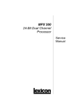
Operating and Service Manual
0040-8174-15001, Rev. M
Prepared By:
47300 Kato Road
Fremont, California 94538
August 2002
8174 HF Monitor Receiver
0040-8174-15001, Rev. M
TABLE OF CONTENTS
Page
1. GENERAL INFORMATION...........................................................................................................1-1
1.1
1.1.1
1.1.2
1.1.3
1.2
1.2.1
1.2.2
1.2.3
1.2.4
1.3
1.4
1.5
Introduction...................................................................................................................................1-1
Scope.............................................................................................................................................1-1
Sections .........................................................................................................................................1-1
Abbreviations ................................................................................................................................1-1
General Description ......................................................................................................................1-1
Introduction...................................................................................................................................1-1
General Features ...........................................................................................................................1-1
Frequency Scan .............................................................................................................................1-3
Remote Control .............................................................................................................................1-3
Equipment Required but not Supplied ..........................................................................................1-3
Publications...................................................................................................................................1-4
Specifications ................................................................................................................................1-4
2. INSTALLATION...............................................................................................................................2-1
2.1
2.2
2.2.1
2.2.2
2.2.3
2.3
2.3.1
2.3.2
2.4
2.5
2.5.1
2.5.2
2.5.3
2.5.4
2.5.5
2.6
2.7
2.7.1
2.7.2
2.8
Introduction...................................................................................................................................2-1
Unpacking and Inspection.............................................................................................................2-1
Shipment .......................................................................................................................................2-1
Unpacking .....................................................................................................................................2-1
Claim for Damage.........................................................................................................................2-1
Installation Requirements .............................................................................................................2-1
Environment..................................................................................................................................2-1
AC Power......................................................................................................................................2-1
Mounting.......................................................................................................................................2-1
Cables and Connections ................................................................................................................2-2
Connections to Other Equipment ..................................................................................................2-2
Connectors Pinouts .......................................................................................................................2-2
Address and Baud Rate .................................................................................................................2-2
10 MHz Connector (J4).................................................................................................................2-6
Interconnect Information...............................................................................................................2-6
Post Installation Checkout ............................................................................................................2-8
Storage and Reshipment................................................................................................................2-8
Storage ..........................................................................................................................................2-8
Reshipment....................................................................................................................................2-8
Electromagnetic Compatibility .....................................................................................................2-8
3. OPERATION.....................................................................................................................................3-1
3.1
3.2
3.2.1
3.2.2
3.3
3.3.1
3.3.2
3.4
Introduction...................................................................................................................................3-1
Receiver Front Panel Controls and Indicators ..............................................................................3-1
Power Switch ................................................................................................................................3-1
Status Indicators............................................................................................................................3-1
Receiver Operation .......................................................................................................................3-1
General ..........................................................................................................................................3-1
AGC Response..............................................................................................................................3-2
External 10 MHz Reference..........................................................................................................3-2
4. THEORY OF OPERATION ............................................................................................................4-1
i
0040-8174-15001, Rev. M
4.1
4.2
4.3
4.4
4.5
8174 HF Monitor Receiver
Introduction...................................................................................................................................4-1
Receiver Board (8400-2006).........................................................................................................4-1
CPU/DSP Board (8074-2004).......................................................................................................4-2
Synthesizer Board (8074-2005 or 8074-2105)..............................................................................4-2
Power Supply and DC Power Filter ..............................................................................................4-4
5. MAINTENANCE...............................................................................................................................5-1
5.1
5.2
5.3
5.4
Model 8174 Receiver Functional Test ..........................................................................................5-1
Repair by Replacement of Boards.................................................................................................5-1
Line Audio Outputs.......................................................................................................................5-1
10 MHz Reference ........................................................................................................................5-2
6. OPTIONS, VERSIONS, AND PRODUCT IMPROVEMENT .....................................................6-1
6.1
6.2
6.3
Introduction...................................................................................................................................6-1
Configurations...............................................................................................................................6-1
Revisions.......................................................................................................................................6-2
7. REMOTE INTERFACE PROTOCOL ...........................................................................................7-1
7.1
7.2
7.3
7.3.1
7.3.2
7.3.3
Introduction...................................................................................................................................7-1
Command Encoding......................................................................................................................7-1
Commands ....................................................................................................................................7-4
Incoming (Into Receivers).............................................................................................................7-4
Outgoing (From Receivers).........................................................................................................7-16
Settings, Codes, and Command Samples ....................................................................................7-22
8. HOW TO USE THE ILLUSTRATED PARTS BREAKDOWN ..................................................8-1
8.1
8.1.1
8.1.2
8.1.3
8.1.4
Introduction...................................................................................................................................8-1
General ..........................................................................................................................................8-1
Parts Lists......................................................................................................................................8-1
Wire Lists......................................................................................................................................8-2
Assembly Drawings ......................................................................................................................8-2
Appendix A - Parts Lists.........................................................................................................................A-1
Appendix B - Wire Lists ......................................................................................................................... B-1
Appendix C - Assembly Drawings .........................................................................................................C-1
Appendix D - Electrical Drawings .........................................................................................................D-1
Appendix E – Model 8074/8174 Virtual Control.................................................................................. E-1
ii
8174 HF Monitor Receiver
0040-8174-15001, Rev. M
LIST OF TABLES
Page
1-1
2-1
2-2
2-3
2-4
7-1
7-2
7-3
7-4
7-5
7-6
7-7
7-8
8-1
Model 8174 Receiver Specifications ............................................................................................1-4
Model 8174 Receiver External Audio Interface Connection -J3 ..................................................2-3
Model 8174 Receiver Serial Control Interface Connection-J2 .....................................................2-4
Switch S1 Remote Control Baud Rate (BPS) Settings .................................................................2-5
Switch S1 Address Settings ..........................................................................................................2-5
Command Encoding......................................................................................................................7-2
Data Block Format ........................................................................................................................7-4
AGC and ALC Settings...............................................................................................................7-22
Bandwidth Selection ...................................................................................................................7-22
Demodulation Selection..............................................................................................................7-22
BITE Returned Error Codes........................................................................................................7-23
Sample Command Sequence.......................................................................................................7-23
Error Codes Returned with NAK Command ..............................................................................7-25
Cage Codes ...................................................................................................................................8-3
LIST OF FIGURES
Page
1-1
2-1
2-2
2-3
2-4
2-5
2-6
4-1
4-2
5-1
6-1
8174 HF Monitor Receiver ...........................................................................................................1-2
8174 Receiver Rear Panel .............................................................................................................2-2
Switch S1, Factory Default Settings .............................................................................................2-5
Computer RS-232 with DE-9 Connector to Single Receiver........................................................2-6
Computer RS-232 with DB-25 Connector to Single Receiver .....................................................2-6
Computer RS-232 with 4-Wire RS-485 Converter to Multiple Receivers ...................................2-7
Computer RS-232 with 2-Wire RS-485 Converter to Multiple Receivers ...................................2-7
Simplified Block Diagram of the Receiver...................................................................................4-1
Simplified Block Diagram of Synthesizer ....................................................................................4-2
Top View of Model 8174 Receiver with Cover Removed............................................................5-3
Identification Plate Format............................................................................................................6-1
iii
8174 HF Monitor Receiver
0040-8174-15001, Rev. M
1. GENERAL INFORMATION
1.1
1.1.1
Introduction
Scope
This manual provides the interface, installation, theory of operation and periodic maintenance
instructions for the TCI Model 8174 HF Monitor Receiver (further referred to as the Receiver). For a
description of the operation of the Receiver via the Virtual Control Panel (VCP), refer to the VCP
Manual, Appendix E.
!
1.1.2
NOTE: The contents of this manual, including specifications, are subject to change without notice.
Sections
The information in this manual is presented in eight sections. Section 1 provides a brief description of
the equipment and operating specifications. Unpacking instructions, cabling data, and installation
instructions are included in Section 2. Section 3 provides operating instructions for the Receiver. Section
4 explains the theory of operation for the Receiver. Section 5 describes preventive maintenance
procedures for the equipment. Section 6 describes the configuration and firmware options of the Receiver.
Section 7 is the interface protocol used in the Receiver. Section 8 presents the top level Illustrated Parts
Breakdown, including parts lists and wire lists. Electrical drawings, including schematics and wiring
diagrams, are grouped together at the end of the manual.
1.1.3
Abbreviations
This manual uses abbreviations found in "Military Standards Abbreviations for Use on Drawings and
in Specifications, Standards and Technical Documents", MIL-STD-12D, whenever possible.
1.2
1.2.1
General Description
Introduction
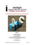
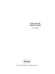
The Model 8174, shown in Figure 1-1, is a general purpose, HF Monitor Receiver. This Receiver
provides digitally demodulated and filtered audio signal outputs and, as an option, a digital panoramic
display of the 6 kHz bandwidth. The 8174 Receiver chassis accommodates a single HF Receiver in a
1.75-inch high, 19-inch wide rack mount enclosure. The Receiver consists of five modules: a receiver
module, a demodulation/control module, a synthesizer module, a power supply module and a DC power
filter.
1.2.2
General Features
The Receiver provides digital filtering and demodulation of AM, CW, LSB, USB and ISB radio
signals in the frequency range 1.5 to 30 MHz at a frequency resolution of 1 Hz. Frequency ranges at the
lower end of the spectrum down to 10 kHz are available as an option. A BFO adjustable over ±8 kHz in 1
Hz steps is provided for CW demodulation mode.
1-1
0040-8174-15001, Rev. M
8174 HF Monitor Receiver
Figure 1-1 8174 HF Monitor Receiver
The Receiver includes six preselection filters located in the receiver module:
1.5–3.0 MHz
3.0–5.25 MHz
5.25–8.5 MHz
8.5–13.25 MHz
13.25–20.0 MHz
20.0–30.0 MHz.
The standard demodulation bandwidths are:
0.3 kHz
0.5 kHz
1.0 kHz
2.2 kHz
2.5 kHz
2.7 kHz
3.0 kHz
3.1 kHz
3.2 kHz*
3.6 kHz*
4.0 kHz*
6.0 kHz.
*Additional bandwidths only available with “Dual-DSP” version of receiver.
The Receiver features one manual and four automatic gain control modes. Receiver gain control
(digital AGC) covers an RF input signal range from –120 to 0 dBm. The digital AGC is further
augmented by an automatic audio level control (ALC) in the DSP demodulation which maintains the
audio output at constant amplitude (±1 dB). The four selectable AGC modes are optimized for AM, SSB
voice, continuous data, and burst data. In addition, a selectable audio squelch control is provided with a
range –126 to 0 dBm.
1-2
8174 HF Monitor Receiver
1.2.3
0040-8174-15001, Rev. M
Frequency Scan
The Receiver has a versatile built-in frequency scanning capability. The operator can program the
Receiver to scan either a discrete frequency list, or over a group of frequency ranges. The scan list can be
set up with up to 100 discrete frequencies or 200 frequency bands (with start/stop frequencies specified).
Also, the scan can be programmed with a combination of discrete frequencies and bands. In addition, up
to 100 lock-out frequencies can be programmed to skip frequencies within scanned bands. If a signal is
detected whose amplitude is above the scan threshold, the scan will stop and momentarily hold on that
frequency. The scan rate (dwell time per frequency) and hold time (holding time after signal detection)
can be programmed over a wide range of values.
1.2.4
Remote Control
There are no front panel controls on this model of the Receiver except for the POWER ON/OFF
switch as shown in Figure 1-1. The unit was designed to be remotely operated under computer control.
Consequently, all Receiver functions are remotely controllable via a serial interface or a serial bus. This
feature allows the Receivers to be installed in locations separated from the operator location.
There are two options available for controlling the Receiver.
1. Through the TCI provided software package “Virtual Control Panel”, or VCP. The VCP
package is a WINDOWS®-based program that allows remote control of up to thirty-one 8174
Receivers on a PC equipped with RS-232 or EIA RS-485 serial interfaces. The VCP software
package includes the source code for user modification to suit specific needs.
2. Through the development custom software (see remote interface protocol in Section 7 of this
manual) to control as required by the user.
1.3
Equipment Required but not Supplied
The user must supply the interconnecting cables (see paragraph 2.5 for additional information about
interconnect cabling):
1. Between RF source and the Receivers RF input (coax, 50 ohm).
2. Computer interface connection (RS-232 or RS-485 from external computer to the Receiver).
3. Audio connection (Receiver balance line or unbalanced speaker audio output).
4. Between external reference 10 MHz and the Receiver 10 MHz input (coax, 50 ohm).
For operation with the VCP software package, the user must supply a PC-compatible computer
running in a WINDOWS® environment. A 3.5-inch diskette drive is required to install the VCP software.
1-3
0040-8174-15001, Rev. M
1.4
8174 HF Monitor Receiver
Publications
There are two publications describing the operation and service of the Model 8174 HF Monitor
Receiver:
Title
Manual No.
Model 8174 HF Monitor Receiver, Operating and Service Manual
0040-8174-15001
Operating Manual, Model 8074/8174 Virtual Control Panel
0040-8074-15003
1.5
Specifications
Table 1-1 lists the technical specifications and tested performance characteristics of the Model 8174
Receiver.
Table 1-1 Model 8174 Receiver Specifications
Configuration:
Remotely controlled, modular single-channel internal Receiver in a 1U
x 19-inch enclosure. The chassis includes a power supply with DC
power filter and a single channel Receiver. A single channel Receiver
consists of three circuit boards: receiver, synthesizer, and CPU/DSP.
Receiver topology:
Synthesized, triple conversion superhet. All RF tuning determined by
1st LO. Direct digital demodulation of 3rd IF output.
Frequency range:
1.5–30 MHz.
Tuning resolution:
1 Hz.
Demodulation modes:
AM, LSB, USB, ISB, and CW.
Bandwidths:
0.3, 0.5, 1.0, 2.2, 2.5, 2.7, 3.0, 3.1, 3.2, 3.6, 4.0, 6.0 kHz (Up to 48
bandwidths possible).
BFO:
Digital synthesis, ±8 kHz, 1 Hz resolution, CW mode only.
Frequency synthesis:
All LOs are fully synthesized and directly referenced to a common
10 MHz frequency reference. Low noise, “Fractional N” synthesizer for
1st LO. Tuning accuracy determined by frequency reference.
Frequency reference:
Internal:
10 MHz TCXO, adjustable to 1 PPM accuracy, with 10 PPM stability
(0° to 50°C), long term aging less than 3 PPM per year.
External:
10 MHz, 1 Vrms (0.5–1.5 Vrms range) into 50 ohm.
Frequency reference output:
10 MHz, ≈ 0.5 Vrm into 50 ohm.
Frequency change response
time:
10 millisecond max after receipt of tuning command to settle to within ±
10 Hz for any size frequency step.
Synthesizer phase noise:
–85 dBc/Hz at 100 Hz offset
–90 dBc/Hz at 1 kHz offset
–95 dBc/Hz at 10 kHz offset
–105 dBc/Hz at 50 kHz offset
1-4
8174 HF Monitor Receiver
0040-8174-15001, Rev. M
Table 1-1 Model 8174 Receiver Specifications
–120 dBc/Hz at 100 kHz offset
–130 dBc/Hz at 200 kHz offset
–140 dBc/Hz at 1 MHz offset.
Antenna input:
50 ohm, 2:1 VSWR typical (3.5 : 1 max).
Preselection:
Six, 3-pole bandpass filters, 40 dB minimum out-of-band rejection.
1.5–3.0, 3.0–5.25, 5.25–8.5,
8.5–13.25, 13.25–20.0, 20.0–30.0 MHz.
(1.5–3.0 MHz filter can be changed to .01–3.0 MHz for special
applications).
Max signal level:
Linear operation up to 0 dBm in-band input. Receiver will withstand up
to +20 dBm input with no damage.
Nominal input signal level range:
0 dBm max to noise floor (–130 dBm in 1 kHz BW).
Front-end attenuation:
Digitally switched 12 dB electronic attenuator.
Noise figure:
15 dB max (14 dB typical), 3–30 MHz.
(front end attenuator off)
17 dB max (15 dB typical), 1.5–3 MHz.
Out-of-band intermodulation
distortion (measured with two –6
dBm input tones above 3 MHz)
2nd-order intercept:
+75 dBm, 1 MHz min. spacing.
3rd-order intercept:
+30 dBm, 100 kHz min. spacing.
IF settling time:
1 ms typical (2.7 kHz bandwidth). Does not include synthesizer
response time.
1st IF:
40.455 MHz, 15 kHz bandwidth crystal filter.
IF rejection:
75 dB min. (80 dB typical).
Image rejection:
80 dB min. (90 dB typical).
2nd IF:
455 kHz tuned IF with mechanical bandpass filter.
2nd IF bandwidth:
6 kHz standard (other bandwidths optionally available).
2nd IF selectivity:
2 : 1 (40 : 3 dB).
Ultimate rejection:
70 dB.
Gain control:
Digital, electronically switched IF attenuators operating on RF and 2nd
IF stages, plus DSP-based amplitude scaling of audio output.
Gain Range:
130 dB range in 1 dB steps.
For receiver module (RF/IF):120 dB range (12 dB in front end, 108 dB
in 2nd IF), in 6 dB steps.
1-5
0040-8174-15001, Rev. M
8174 HF Monitor Receiver
Table 1-1 Model 8174 Receiver Specifications
AGC response:
15 ms attack, selectable release time constants: ’Fast’ (50 ms),
’Medium’ (0.2 sec), and ’Slow’ (4 sec hang with 1 sec decay) including
hang time. ’Slow Data’ optimizes the ’Slow’ response for burst data
applications (fast, peak detecting attack with slow decay).
AGC threshold:
Adjustable from –120 dBm to 0 dBm.
RF input level measurement:
Digital report (via remote control interface) of RF input power.
Squelch:
Automatic muting of audio output when RF input power level drops
below user-programmed level.
Squelch threshold range:
Adjustable from –126 dBm to 0 dBm.
3rd IF center frequency:
5.0 kHz (for standard bandwidth).
3rd IF output level:
2.0 volts p-p nominal into 1000 ohm.
3rd IF output headroom:
12 dB minimum above nominal.
Digital Signal Processor:
Single or optional dual TMS320 series Digital Signal Processor(s)
provide FIR filtering of signal bandwidth, BFO, automatic leveling of
audio output, and optional PAN adapter display, or optional
demodulation and control functions.
DSP demodulation bandwidth:
300 Hz min to 6 kHz max depending on demodulation mode (for
standard IF bandwidth).
DSP demodulation filtering:
FIR filters with 1.5:1 shape factor (60:3 dB typical).
DSP audio scaling:
40 dB range in 1 dB steps.
Audio outputs:
Two 600 ohm balanced Line Audio outputs (MAIN and AUX, or one for
each sideband in ISB), plus one 8 ohm unbalanced Monitor Audio
output. Monitor Audio features addressable On/Off switching of output
which allows Monitor Audio outputs from many receiver channels to be
bussed together to a common audio device (e.g., headphones).
Selected audio from one of up to 31 bussed receiver channels can be
individually selected through remote control interface.
Line Audio output:
0.77 Vrms nominal, (0 dBm) into 600 ohm. Internally adjustable down
to –10 dBm nominal. Audio level is also externally programmable
through the remote control interface.
Monitor Audio output:
250 mW into 8 ohm. Signal source for Monitor Audio externally
selectable through remote control interface from Main or Aux Line
audio outputs.
Calibrator (BITE):
–70 dBm ±2 dB, 500 kHz comb (1.5–30 MHz) relay-switched in place
of antenna RF input.
Built-in test (BIT);
Automatic testing, of power supply, synthesizer, receiver, and DSP
using internal test circuitry (BITE). Results are reported through the
remote control interface. Continuous status of major errors available
through front panel LEDs.
1-6
8174 HF Monitor Receiver
0040-8174-15001, Rev. M
Table 1-1 Model 8174 Receiver Specifications
Remote control:
ASCII serial data, RS-485 addressable interface, selectable from 300
to 19200 baud. Remote control lines for up to 31 receiver channels
can be bussed together and connected to a single RS-485 remote
controller. (Equipment can also be configured for use with RS-232/422
or MIL-STD-188-114 interface, suitable for remotecontrol from PC
computers.)
Remote control address:
Rear panel DIP switch selection of address 01 through 31 for receiver
channel. Remote commands are executed only by the receiver
channel with DIP switch address matching the command address
header.
Virtual Control Panel:
IBM PC- compatible application software running under Microsoft
Windows® to provide local control and readout of all Receiver
functions.
Frequency scans:
Automatic scanning of up to 100 discrete frequencies, or up to
200 bands (each band defined by Start and Stop frequencies). Up to
100 lock-out frequencies may be programmed to skip frequencies
within scanned bands. Scans may include any combination of discrete
frequencies and bands. Frequencies programmable to 1 Hz resolution.
Scan increment (within a band) programmable from 1 Hz to 100 kHz
step size. Scan dwell time programmable from 50 ms to 10 per
frequency. Scan dwell times down to 10 ms per frequency available for
receivers using optional rapid tuning digital (DDS) synthesizer.
AC line power:
Autosensing 115 or 230 VAC, 50-60 Hz, 30 watt max.
AC power switch:
Front panel rocker switch.
Cooling:
Convection.
Front panel indicators:
•
DC POWER (green LED). Indicates DC power to internal
modules is ON.
•
RUN (green LED). Indicates CPU/DSP is operating.
•
FAULT (red LED). Indicates synthesizer lock error.
Mounting:
EIA RS-310 19-inch rack mount. Enclosure includes threaded inserts
on side panels for mounting rack slides.
Size:
1.75"h x 19"w x 23"d.
Weight:
11 lb. (5 kg.)
Shipping Weight: 20 lb. (9.1 kg.)
Temperature range:
Operating: 0° to +50°C short term, +5° to +40°C long term and
for optimum performance.
Non-operating: –40° to +70°C.
Humidity:
0–95% Relative Humidity.
Altitude:
10,000 feet operating, 40,000 feet non-operating.
1-7
0040-8174-15001, Rev. M
8174 HF Monitor Receiver
Table 1-1 Model 8174 Receiver Specifications
Rear panel connectors:
Antenna input:
BNC
Remote Control input:
15-pin High Density D (HDD-15S)
Audio output:
9-pin D/sub connector (DE-9P)
AC line power:
IEC 320/VI
10 MHz:
BNC
OPTIONS
Frequency range:
0.01–30 MHz.
Frequency reference Internal:
Premium:
10 MHz TCXO, adjustable to 1 PPM accuracy, with 1 PPM (0° to 50°C)
or 0.5 PPM (15° to 35°C) stability, long term aging less than 1 PPM per
year.
Low cost:
10 MHz XO, 100 PPM accuracy (0° to 50°C).
Frequency change response
time (for premium
synthesizer):
1 ms max after receipt of tuning command to settle to within +1 Hz for
any size frequency step.
2nd IF filter:
3 kHz or 12 kHz bandwidth filter instead of standard 6 kHz 3 kHz filter
provides greater sensitivity, selectivity, and dynamic range for
applications not requiring ISB or full AM operation. 12 kHz provides
greater bandwidth (at the expense of sensitivity, selectivity and dynamic
range) for applications requiring wider demodulation bandwidths.
DSP demodulation
bandwidths:
Custom filters of any bandwidth from 100 Hz minimum to 12 kHz
maximum, e.g., optional CW bandwidths available in any odd multiples
of 100 Hz.
IF output:
455 kHz 2nd IF (–40 dBm into 50 ohm) or 5 kHz 3rd IF (1 V into 1000
ohm).
Digital I & Q outputs:
DSP generated digitized quadrature-phase outputs of 3rd IF.
Pan display:
Internal FFT processor provides digital spectrum data of the 6 kHz
bandwidth IF as an aid for tuning or examining received signal
characteristics. Up to thirty, 128-point FFT transforms per second (50 Hz
resolution over 6 kHz) with up to 60 dB in-band amplitude range.
1-8
8174 HF Monitor Receiver
0040-8174-15001, Rev. M
2. INSTALLATION
2.1
Introduction
This section contains instructions for installing the Model 8174 HF Monitor Receiver and for making
all necessary cable interconnections before putting the Receiver to use. Details on storage and reshipment
are also included.
2.2
2.2.1
Unpacking and Inspection
Shipment
The Receiver is shipped from the factory in a fully assembled condition (except for interconnect
cabling). For shipment, the unit is enclosed in a moisture resistant barrier material with desiccant and
humidity indicator. The unit is then packed in a cardboard shipping box. The maximum weight of the
equipment is approximately 11 lb. (5 kg). The shipping weight of the unit in the packing case is
approximately 20 lb. (9 kg).
2.2.2
Unpacking
To unpack the Receiver, open the top of the packing box and lift the unit out of the case. Check all
items against the packing list. The shipping container and associated packing material should be retained
for possible use in reshipment or storage of the unit.
2.2.3
Claim for Damage
If the Receiver is mechanically damaged or fails to meet specifications on receipt, notify the carrier
and TCI. Retain the shipping carton, packing boxes and the padding material for the carrier’s inspection.
2.3
2.3.1
Installation Requirements
Environment
The Receiver operates satisfactorily within the temperature limits of +5° to + 40°C (0° to +50°C short
term). The unit will operate satisfactorily after exposure to transport or storage temperatures between
minus 40° to +70°C. The Receiver is not designed for direct exposure to outdoor environments.
2.3.2
AC Power
The Receiver can be operated at either 115 or 230 volts ±10%, 50/60 Hz AC. Voltage changeover is
automatic.
2.4
Mounting
The Receiver is designed for installation into a standard 19-inch EIA rack. The unit requires 1U (or
1.75 inches) of vertical rack space. The maximum depth is 23-inches not including rear panel connectors.
2-1
0040-8174-15001, Rev. M
8174 HF Monitor Receiver
Optional rack slide mount hardware is also available. An air space should be provided above and
below the unit to allow free air circulation to cool the unit.
2.5
Cables and Connections
2.5.1
Connections to Other Equipment
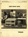
The rear panel of the Receiver is shown in Figure 2-1.
MON
1
0
AUDIOOUT
10MHz
FUSE1A
ACPOWER
12 3 4 5 6 78
GND
S1
R3
Figure 2-1 8174 Receiver Rear Panel
The external connections are as follows:
1. Between J5 and the AC power source (the supplied AC power cord).
2. Between the ground stud on the rear panel and the site grounding system (safety ground).
3. Between J3 and Audio Speaker and/or Audio Line.
4. Between J2 and the Host Computer.
5. Between J1 and the RF source.
6. Between J4 and the 10 MHz source (see paragraph 2.5.4).
2.5.2
Connectors Pinouts
The connectors pinouts for multipin control and audio cables are tabulated in Table 2-1 (J3) and
Table 2-2 (J2).
2.5.3
Address and Baud Rate
Switch S1 on the rear panel of the Receiver chassis is an eight position DIP switch that sets both the
remote control protocol “address” of the receiver channel, and speed of remote control data
communications (baud rate) between the Receiver and the external computer.
The Receiver is typically shipped from the factory with standard factory settings of 19200 bits/second
and ADDR 1, as shown in Figure 2-2. If other settings are needed, set switches S1-1 through S1-3 for the
desired baud rate as shown in Table 2-3. Set switches S1-4 through S1-8 to set the channel address as
shown in Table 2-4. Each receiver channel (i.e., each CPU/DSP module) can be set to respond to a
specific address (defined in the 8174 Receiver remote interface protocol) from the external remote control
computer. The address is determined by a 5-bit number programmed on switches S1-4 through S1-8.
Valid addresses are 01 through 31 decimal (00001 through 11111 binary). Switch S1-8 is the least
significant bit (LSB) and S1-4 is the most significant bit (MSB) of the 5-bit address number. If the
2-2
8174 HF Monitor Receiver
0040-8174-15001, Rev. M
switches are all set to 0, the Receiver’s internal CPU will convert setting 00000 to address 01. This is
done because address 00 is reserved in the remote control protocol for commands issued to all receiver
channels simultaneously. That is, if the external remote control computer issues a command to address
00, all receivers will respond to that command regardless of the address set by switches S1-4 through
S1-8.
The serial remote control interface operates using standard ASCII printable characters. The serial RS232 interface is either 7 or 8 data bits per character (the parity bit is ignored by the Receiver) plus single
"start" and "stop" bits, yielding a total of 9 or 10 bits per character (see Section 7 of this manual for
additional information).
Table 2-1 Model 8174 Receiver External Audio Interface Connection -J3
J3 = Male 9-pin D-submin connector (DE-9P).
Pin
J3-1
J3-2
J3-3
J3-4
J3-5
J3-6
J3-7
J3-8
J3-9
Signal Name
HEAD
AGND
MAIN
MAIN
AUX
AUX
Description
Speaker 250mW @ 8Ω (Monitor Audio)
Analog signal ground return for speaker
Line Audio out, balanced pair wire A.
Line Audio out, balanced pair wire B.
Not Used
Line Audio out, balanced pair wire B.
Line Audio out, balanced pair wire A.
Not Used
Not Used
The MAIN and AUX line audio outputs provide the same signal in all modes except ISB. In ISB mode, MAIN supplies
the upper sideband signal and AUX supplies the lower sideband signal. The HEAD speaker monitor audio output can
be selected from the MAIN or AUX audio signal through the remote control interface. The MAIN and AUX line audio
volume levels, and the HEAD on/off control can be programmed independently through the remote control interface.
NOTE: The cable plug mating connector for J3 is a standard female 9-socket subminiature D (DE-9S). This
connector is optionally available from TCI. Order TCI part number 1242-0180 for the connector and part number
1242-0268 for the connector backshell. Alternatively, order TCI part number 8074-1901-006 for a prefabricated 6-foot
(2-meter) long audio cable assembly. This cable assembly contains a pre-wired cable plug that mates to J3 on one
end, and uncommitted "pig-tail" wires on the other end.
2-3
0040-8174-15001, Rev. M
8174 HF Monitor Receiver
Table 2-2 Model 8174 Receiver Serial Control Interface Connection-J2
J2=Female high density 15-pin D-submin connector (HDD-15S)
Pin
J2-1
J2-2
J2-3
J2-4
J2-5
Signal Name
SA
Rx
Tx
GND
GND/REF
J2-6
J2-7
J2-8
J2-9
J2-10
J2-11
J2-12
J2-13
J2-14
J2-15
J2-Backshell
DSR
Rx REF
CTS
SB
DX Out
DR In
Drain
Description
Serial bus, positive (EIA-485)
Serial receive (RS-232)
Serial transmit (RS-232)
Chassis
Signal ground for RS-232/
Tx REF for RS-422/RS-423
Pull up to +5V through 10K Ω
Rx REF for RS-422/RS-423
Pull up to +5V through 10K Ω
Serial bus, negative (EIA-485)
Reserved
Reserved
Data transmit (for CPU/DSP card with Pan display Option)
Reserved
Reserved
Data receive (for CPU/DSP card with Pan display Option)
Cable shield
NOTE: The cable plug mating connector for J2 is a male 15-pin high density subminiature D (HDD-15P). This
connector is optionally available from TCI. Order TCI part number 1242-0274 for the connector shell, and 15 each of
part number 1242-0275 for the connector contacts. Also order part number 1242-0268 for the connector backshell.
Alternatively, order TCI part number 8074-1902-006 for a prefabricated 6-foot (1.8-meter) long control cable
assembly. This cable assembly contains a pre-wired cable plug that mates to J2 on one end, and uncommitted "pigtail" wires on the other end.
Also available are completely pre-wired cable assemblies to connect receiver control connector J2 to the RS-232
COM ports of a computer. Cable part number 8074-1904-010 is 10 feet (3 meters) long and provides a mating
connector for J2 on one end (HDD-15P) and a single 9-pin female RS-232 connector on the other end (DE-9S). If the
Pan Display option is installed in the receiver, the two RS-232 ports are required on the external computer. Cable part
number 8074-1905-010 is a pre-wired, 10-foot long cable assembly that connects the receiver (J2) to two RS-232
computer ports. This cable provides a mating connector for J2 on one end (HDD-15P) and two 9-pin female RS-232
connectors on the other end (two DE-9S).
2-4
8174 HF Monitor Receiver
0040-8174-15001, Rev. M
BAUD
RATE
ADDRESS
UP = 1
DOWN =0
1
2
3
4
5
6
7
8
SWITCH 1
Shown with Factory Default Settings for
19200 bps (Baud Rate setting 111) and
Address 01 (Address setting 00000)
Figure 2-2 Switch S1, Factory Default Settings
Table 2-3 Switch S1 Remote Control Baud Rate (BPS) Settings
S1-1
S1-2
S1-3
BPS
1
1
1
1
0
0
0
1
1
0
0
1
1
0
1
0
1
0
1
0
1
19200
4800
9600
600
2400
300
1200
Table 2-4 Switch S1 Address Settings
!
S1-4
S1-5
S1-6
S1-7
S1-8
Address
1
1
1
0
1
1
0
1
1
1
0
0
1
1
0
0
1
0
0
0
0
0
0
0
0
0
0
0
0
0
0
0
1
1
0
0
0
0
0
0
1
1
0
0
1
0
1
0
1
0
31
30
16
08
etc.
05
04
03
02
01
See NOTE
NOTE: If S1-4 through S1-8 are all set to 0, the channel address will default to address 01
2-5
0040-8174-15001, Rev. M
2.5.4
8174 HF Monitor Receiver
10 MHz Connector (J4)
Rear panel connector J4 can be used as either a 10 MHz external frequency reference input, or a
10 MHz reference signal output. Selection of ‘input’ or ‘output’ is determined by changing a
connectorized jumper cable inside the Receiver. When shipped from the factory, J4 is normally
configured for ‘input’. That is, the standard configuration of the Receiver uses J4 to provide a means to
apply an external 10 MHz frequency reference (such as a “station standard”) to lock the frequency
synthesizer in the Receiver to an external frequency standard (see paragraph 3.4 of this manual). If no
external standard is connected to J4, the internal synthesizer will lock to its own internal 10 MHz
reference oscillator. If J4 is configured as an output, a buffered 10 MHz signal derived from the
Receiver's synthesizer internal reference oscillator is available. This 10 MHz output at J4 has an
amplitude of approximately +10 dBm (into 50 ohm).
2.5.5
Interconnect Information
Figures 2-3 through 2-6 illustrate connections between the 8074/8174 receiver and a computer used to
control them.
Figure 2-3 Computer RS-232 with DE-9 Connector to Single Receiver
Figure 2-4 Computer RS-232 with DB-25 Connector to Single Receiver
2-6
8174 HF Monitor Receiver
0040-8174-15001, Rev. M
Figure 2-5 Computer RS-232 with 4-Wire RS-485 Converter to Multiple Receivers
Figure 2-6 Computer RS-232 with 2-Wire RS-485 Converter to Multiple Receivers
2-7
0040-8174-15001, Rev. M
2.6
8174 HF Monitor Receiver
Post Installation Checkout
The electrical performance of the Receiver should be verified after installation. The tests described in
Section 5 of this manual should be performed as the post-installation checkout prior to operation. In
addition, overall performance should be periodically verified by these tests.
2.7
2.7.1
Storage and Reshipment
Storage
The maximum recommended storage environment should not exceed –40° to +70°C temperature and
95% humidity. For long term storage, repackaging of the equipment and sealing of the cables into
moisture proof bags is recommended.
2.7.2
Reshipment
The Receiver should be packaged carefully in a moisture resistant container for reshipment. The unit
should be surrounded by high density foam and securely packed in a wooden crate for reshipment.
2.8
Electromagnetic Compatibility
The Model 8174 Receiver is designed to operate in typical HF radio environments in mobile or fixed
installations in accordance with the guidelines of MIL-STD-5400 and MIL-STD-461C (Part 2, Class A1)
for Electromagnetic Compatibility (EMC) in terms of electromagnetic interference and susceptibility
to/from other electronic equipment. However, the Receiver does not necessarily meet all spec limits
defined by MIL-STD-461C at all frequencies. Refer to the Receiver specifications in Section 1 of this
manual for specified performance.
2-8
8174 HF Monitor Receiver
0040-8174-15001, Rev. M
3. OPERATION
3.1
Introduction
This section provides the basic information required to use the Receiver. It is a brief description of the
controls and indicators of the unit itself.
3.2
Receiver Front Panel Controls and Indicators
3.2.1
Power Switch
The front panel has a POWER ON/OFF rocker type switch. Turn this switch ON to use the Receiver.
3.2.2
Status Indicators
There are three status LEDs on the Receiver’s front panel. The significance of each LED is (from left
to right):
a. DC POWER. Green LED indicates DC power to internal modules is ON.
b. RUN. Green LED indicates CPU/DSP is running.
c. FAULT. Red LED indicates synthesizer lock error.
During normal operation, with the POWER switch ON, the front panel DC POWER and RUN LEDs
will illuminate green and FAULT LED will not be illuminated. If either red LED turns on, or if either
green LEDs go out, there is a problem with the Receiver that may affect its operation or performance.
!
3.3
3.3.1
NOTE: The FAULT LED may flash momentarily when scanning (Channel Scan) or when making
frequency changes over a MHz. When making large frequency changes, the synthesizer may
momentarily break lock which may cause the red FAULT LED to flash momentarily. This is
normal as long as the flash is brief, i.e., less than 0.1 seconds.
Receiver Operation
General
All normal operating functions of the Receiver are externally controlled by a remote PC computer.
They include: tuned frequency, demodulation mode, demodulation bandwidth, BFO, gain control,
squelch, audio output volume, scan modes, scan parameters, built-in test, and receiver status monitoring.
These functions are user-controllable with the standard 8074 VCP software package or other custom
(user-generated) remote control software application.
3-1
0040-8174-15001, Rev. M
3.3.2
8174 HF Monitor Receiver
AGC Response
The Receiver has selectable AGC (and ALC) response characteristics. There are four standard AGC
modes: Fast, Medium, Slow, and Slow Data. Suggested uses are:
‘Fast’
‘Medium’
‘Medium’
‘Slow’
‘Slow Data’
3.4
for typical SSB HF high speed data modem.
for typical SSB HF low/medium speed data modems.
for AM modulation.
for SSB voice or keyed CW.
for burst-type data with narrow bursts that occur infrequently.
External 10 MHz Reference
The internal synthesizer can be locked to an external 10 MHz frequency reference (“Station
Standard”). An accurate station standard frequency reference will improve the frequency accuracy of the
Receiver.
The Receiver accepts a sine-wave (or square wave) external 10 MHz reference 0.5–1.5 Vrms range.
The input impedance of the external 10 MHz input is 50 ohm. When the proper external 10 MHz
reference is connected to the Receiver rear panel BNC jack J4, the synthesizer will automatically switch
off the internal 10 MHz reference and use the external reference instead.
The external 10 MHz reference must be free of spurious (e.g., power line hum) and noise. In general
phase modulated hum sidebands should be –80 dBc and phase noise should be less than –120 dBc/Hz at
1 kHz offset.
3-2
8174 HF Monitor Receiver
0040-8174-15001, Rev. M
4. THEORY OF OPERATION
4.1
Introduction
This section describes the function and operation of internal boards of the Model 8174 HF Monitor
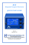
Receiver. Figure 4-1 is a simplified block diagram of the Receiver.
RF IN
J14
8400-2006
RECEIVER (A2)
J11
J12
J13
3RD IF
W2
J14
8074-2004
CPU/DSP (A3)
CONTROL
W6
J11
J13
J3
DEMODULATED
AUDIO
J2
REMOTE
CONTROL
10 MHz
10 MHz
W3
W5
+5 VDC
+15 VDC
1st LO
W4
J13
J11
J12
–15 VDC
POWER
SUPPLY
(A4)
115/230
VAC
DC POWER
FILTER (A5)
8074-2005 or 8074-2105
SYNTHESIZER
J14
(A1)
970410
J1
Figure 4-1 Simplified Block Diagram of the Receiver
4.2
Receiver Board (8400-2006)
The 8400-2006 is the RF/IF section of the Receiver. The Block Diagram of this board (Drawing No.
8400-4206) is provided in the foldout section of this manual.
The 8400-2006 accepts an RF signal (at J1) in the 1.5 to 30 MHz range (optionally .01–30 MHz), and
converts it to 5 kHz at the 3rd IF output with a nominal output level of 2 volts peak-to-peak. The signal
first passes through a VHF filter to reject any image frequencies or possible LO emissions. Next is a bank
of six sub-octave preselection filters. The signal is then converted to 40.455 MHz in the first mixer. After
passing through an amplifier, switchable attenuator, and a 15 kHz BW filter, the signal is mixed down to
455 kHz. The signal is further amplified and filtered to its final bandwidth, optionally 3, 6, or 12 kHz.
The signal now makes its way through 80 dB of amplification and 84 dB of switchable attenuation, in 6
dB increments. Finally, the signal is mixed and amplified to the 3rd IF output. The receiver also produces
a linear detector output whose nominal level is 1 volt. The receiver functions are controlled by a series of
four control bytes. These bytes specify the address of the receiver module to be controlled, set the
receiver gain to a resolution of 6 dB, select the active preselector, and enable/disable the calibrator
(BITE).
4-1
0040-8174-15001, Rev. M
4.3
8174 HF Monitor Receiver
CPU/DSP Board (8074-2004)
The CPU portion of the 8074-2004 controls the basic operation of the Receiver. It communicates
through a serial port with the outside world. At the same time, it controls the actions of the DSP(s) in the
DSP portion of this board, receiver (RF/IF) and synthesizer boards. The primary DSP is used to
demodulate and filter the 3rd IF signal. The Line and Monitor Audio outputs of the Receiver are
generated by the primary DSP and fed to a dual A/D converter for reconstruction back to analog signals.
The Receiver uses 14-bit A/D converters and 32-bit DSPs to provide superior demodulation accuracy and
linearity. The optional second DSP can be programmed as required for optional features of the Receiver.
For example, one of second DSP functions is the Pan display data generator. The second DSP input data
can be obtained directly from the 3rd IF, or from the output of the primary DSP. The second DSP output
is through a digital serial interface only.
4.4
!!
Synthesizer Board (8074-2005 or 8074-2105)
NOTES: 1. Both Synthesizer boards have the same features and functions, but different layout.
2. The documentation on both synthesizers is provided in the foldout section of this
manual.
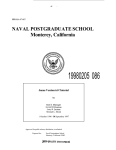
Refer to block diagram, Figure 4-2. The Synthesizer circuit is a digitally programmed, "Fractional N",
phase-locked-loop synthesizer capable of generating any frequency between 40 and 70 MHz to 1 Hz
resolution. It consists of a 40–70 MHz VCO, a programmable divider (÷N), a phase detector and loop
amplifier, and control logic (phase register and timing generator). Figure 4-2 is a simplified block
diagram of the synthesizer.
PHASE
DETECTOR
LOOP AMPLIFIER
100 kHz
REFERENCE
INPUT
FREQ
PROGRAM
INPUT
VCO
PHASE
REGISTER
RESIDUE
LOGIC
RESIDUE
GENERATOR
FRACTIONAL PHASE CORRECTION
÷N
COUNTER
Figure 4-2 Simplified Block Diagram of Synthesizer
4-2
42-70 MHz
OUTPUT
8174 HF Monitor Receiver
0040-8174-15001, Rev. M
The output frequency of the VCO (and the synthesizer) is determined by electrically tuning the VCO
with a control voltage from the loop amplifier. The loop amplifier produces this control voltage by
integrating (smoothing) the phase error signals generated by the phase detector. If there is no phase error,
the output of the phase detector is zero and the loop amplifier will hold the VCO at its existing frequency.
If there is a phase error the detector will drive the loop amplifier to change the VCO frequency until the
error is corrected.
The synthesizer uses the phase detector to compare the output of the ÷N counter with a fixed 100 kHz
reference signal. If the phase or frequency of these two signals do not match, the phase detector will drive
the loop amplifier to adjust the VCO frequency until the ÷N output exactly matches the 100 kHz
reference, thereby achieving phase lock.
The VCO output frequency is always N times 100 kHz. There are N cycles of the VCO output for
every one cycle of the 100 kHz reference. If N is an integer number, the VCO frequency will be an exact
multiple of 100 kHz. However, if N is a number consisting of both integer and fractional components,
intermediate frequencies between 100 kHz points may be synthesized. For example, to produce a
43.5 MHz output the ÷N counter must divide by 435. If an output of 43.501 MHz is desired, the required
divide ratio is 435.01. The ÷N counter, however, is a 3 decade counter only capable of dividing by integer
numbers between 400 and 700. To divide by 435.01 the phase register circuitry programs the ÷N to divide
by 435 for 99% of the time and divide by 436 for the remaining 1%. The resulting average divide number
is:
(99 x 435) + (1 x 436)
100
= 435.01
Because the synthesizer basic timing reference is 100 kHz, the ÷N counter completes a count
sequence (frame) every 10 µs. In the above example the ÷N will count 435 VCO cycles (zero crossings)
for ninety-nine 10 µs frames and 436 cycles for one frame. The phase detector and loop amplifier will
then try to drive the VCO to operate at 43.50 MHz for 990 µs and at 43.60 MHz for 10 µs. The resulting
VCO output is a phase modulated signal with an average center frequency of 43.501 MHz with 1 kHz
sidebands. The 1 kHz sidebands result from the “jumps” in VCO frequency occurring every one
millisecond (990 µs + 10 µs = 1 ms).
The amplitude of the sidebands can be reduced by smoothing the “jumps” in frequency such that the
VCO remains steady at the average frequency and does not follow the loop back and forth between the
two programmed frequencies. However, to reduce the sidebands to an acceptable level (-50 dBc) requires
smoothing (slowing) the loop response to such an extent that the synthesizer would no longer be suitable
for sweeps used in Chirpsounder applications.
These sidebands may be canceled however, by using a fast loop and a fractional phase correction
circuit operating in conjunction with the ÷N.
Note that the average frequency of the VCO is correct. Therefore the average value (or dc
component) of the VCO control voltage from the loop amplifier is correct. The undesired 1 kHz
sidebands are produced by the sudden phase errors generated when the ÷N counter “jumps” between the
two programmed integer divide numbers. This produces a small momentary change in the VCO control
voltage which modulates the VCO frequency resulting in sidebands. The fractional phase correction
circuit cancels the VCO modulation by injecting a compensating phase error correction signal into the
loop amplifier to counteract the effect of the phase error jump when the ÷N skips from one divide ratio to
4-3
0040-8174-15001, Rev. M
8174 HF Monitor Receiver
another. The phase register keeps track of when to “skip” the ÷N from one divide ratio to the next and
simultaneously programs the residue logic of the fractional phase correction circuits. The residue logic
determines the phase correction that must be made in each 10 µs frame to cancel the fractional phase
error. The residue logic drives the residue generator, which produces the fractional phase error correction
signal that is injected into the loop amplifier. By careful alignment of the residue generator, the
synthesizer sidebands can be suppressed better than 50 dB below the fundamental frequency output level.
The ÷N counter consists of a VCO prescaler which typically divides the VCO output frequency
by 2. The prescaler also contains a pulse skipper circuit that makes the ÷2 circuit skip one extra VCO
clock pulse each time a skip command is given. This effectively turns the prescaler into a ÷3 circuit
during a skip command. The output of the VCO prescaler drives the VCO divider. The combination of the
VCO divider and the VCO prescaler is capable of dividing by any integer number between 400 and 700.
For example, to divide by 437, the VCO divider counts 430 times and the VCO prescaler skips 7 extra
VCO clocks during the count sequence, yielding a total count of 437.
The phase register accepts 4-bit binary-coded-decimal (BCD) frequency program data from the
frequency programmer. All 8 decades of BCD data are transferred serially on a decade by decade basis
every 10 µs. All timing signals needed by the synthesizer are produced by the timing generator circuit.
The timing generator controls the transfer of frequency data to the phase register and ÷N counter, and
controls the timing of the fractional phase correction (residue) circuitry.
Control of the synthesizer is accomplished by the use of four data lines, two controls lines and a
strobe line. The control and data information is presented and then read by the synthesizer when the
strobe line is pulsed. The lock detector also outputs a status bit which can be read by the CPU.
4.5
Power Supply and DC Power Filter
The Receiver uses a high reliability switching power supply module that outputs +5 VDC/1.5A,
+15 VDC/1.2A and –15 VDC/0.3A to the DC Power Filter (8174-2001-01). The filtered outputs are
routed to the synthesizer, receiver and CPU/DSP boards. Each of these boards provide more line
regulation and voltage breakdown to meet internal circuit needs.
4-4
8174 HF Monitor Receiver
0040-8174-15001, Rev. M
5. MAINTENANCE
5.1
Model 8174 Receiver Functional Test
Perform the following functional test on the Receiver following installation and cable interconnection
as described in Section 2, and after installation of VCP software as described in Manual
0040-8074-15003, Section 3.
a. Verify that the RF input into the unit is connected to an antenna or other RF source.
b. Turn the computer and Receiver on and enter the 8074 VCP program.
c. When starting the program, the software searches for the Receiver over the serial control port. If
it is not found, an error message is displayed on the screen. When this message is displayed, it is
most likely that the Comm port is not set up correctly. Enter the VCP and set up the Comm port
as described in the manual 0040-8074-15003, section 3. After resetting the Comm port, exit the
VCP application and then restart it.
d. After successfully entering the VCP program without error messages, exercise some of the basic
Receiver controls (i.e., use mouse to enter drop-lists and menus, etc.) to verify that the computer
interface is functional.
e. Perform BITE test to verify Receiver is functioning correctly.
f.
Change the frequency to a known signal of opportunity or a known RF source.
g. Use the Receiver controls to properly set Receiver parameters and to listen to detected signal, to
verify that the parameters change as expected.
5.2
Repair by Replacement of Boards
All boards of the Receiver are mounted to the bottom of the chassis and accessed by removing the top
cover of the Receiver (see Figure 5-1). All of them can be replaced with spared boards.
After removing the top cover, unplug the connectors and remove any board in question by loosening
the hold-down screws, and then pulling the board directly up. Replace with a known working board, and
replace the hold-down screws.
5.3
Line Audio Outputs
The nominal level of the line audio outputs can be set by adjusting variable resistors (potentiometers)
R1 and R2 on the CPU/DSP board inside the Receiver. (Remove the unit top cover for access to the
CPU/DSP board as shown in Figure 5-1.) R1 sets the AUX line audio level and R2 sets the MAIN line
audio level. The nominal levels are typically set to 0 dBm (into 600 ohms) at the factory, but may be
independently adjusted over a range of approximately +3 to –13 dBm.
5-1
0040-8174-15001, Rev. M
5.4
8174 HF Monitor Receiver
10 MHz Reference
Rear panel connector J4 is normally configured for a 10 MHz external frequency reference input. To
change J4 to a 10 MHz output:
a. Remove the top cover of the unit.
b. Follow the coax cable from rear panel J4 to a pair of SMB jacks (J7 and J8) on the metal shield
separating the synthesizer board from the power supply compartment. This coax is normally
connection to J7 which is the 10 MHz INPUT to the synthesizer.
c. To convert J4 to an OUTPUT, disconnect the coax cable from J4 that normally connects to J7 and
connect it to J8 instead. To disconnect, grasp the mating coax plug on the end of the cable and
pull straight back from the shield towards the rear panel until the connectors separate. Then
reconnect to J8 by pushing the plug straight on to J8 until it clicks into place. J8 is the synthesizer
10 MHz output and is located right next to J7. Note that connectors J7 and J8 are not labeled. See
Figure 5-1 to identify the locations of J7 and J8.
d. Replace the top cover of the unit.
5-2
8174 HF Monitor Receiver
0040-8174-15001, Rev. M
Line Audio Output
Level Adjust
J5
F1J4
J3
J2
J1
R2
R1
SMB JACK J7
10 MHz
Reference Input to
Synthesizer
POWER
SUPPLY
(A4)
DC
FILTER
(A5)
SMB JACK J8
10 MHz
Buffered Output from
Synthesizer
CPU/DSP
(A3)
RECEIVER
(A2)
SYNTHESIZER
(A1)
FRONT
Figure 5-1 Top View of Model 8174 Receiver with Cover Removed
5-3
8174 HF Monitor Receiver
6.
6.1
0040-8174-15001, Rev. M
OPTIONS, VERSIONS, AND PRODUCT
IMPROVEMENT
Introduction
The Model 8174 Receiver is available with different hardware options, hardware configurations, and
firmware (software) versions. These options and versions are encoded in the part number (on rear panel)
as explained below. This section describes the options and versions applicable to the unit bearing the
appropriate part number. Product improvement information related to the application of these options
and/or versions is also provided in this section.
6.2
Configurations
The Receiver may be ordered in a number of different configurations, depending upon the needs of
the user. The following information explains the top assembly part numbering convention which is
marked on the 8174 Receiver ID tag located on the rear panel. The ID plate format is shown in
Figure 6-1.
NAME
TCI/BR
MODEL
P/N
UNIT
(1st 4 digits)
TECHNOLOGY FOR COMMUNICATIONS
INTERNATIONAL/BR COMMUNICATIONS
HF DIGITAL RECEIVER
CONFIGURATION
(last 9 digits-see
Section 6)
8174-1603-03-061
95068
S/N
MADE IN USA CAGE CODE 6E696
SERIAL
NUMBER
Figure 6-1 Identification Plate Format
The complete 8174 Receiver is identified by a 13-digit part number of the following formats:
8174-15AA-BB-CCD or 8174-16AA-BB-CCD, where:
AA indicates the type of synthesizer (8074-2105) used in the unit. There are currently three
versions available that define the stability and accuracy of the internal 10 MHz frequency
standard within the synthesizer; AA=01 for 100 ppm stability, AA=02 for 10 ppm, and
AA=03 for 1 ppm.
BB indicates the firmware of the CPU/DSP (8074-2004). There are two available; standard
(BB=03), and with pan display option (BB=04).
CC indicates the version of receiver (8400-2006). Standard for the 8174 Receiver for general
purpose monitoring applications is CC=03, applications with extended frequency range at the
lower end is CC=06.
6-1
0040-8174-15001, Rev. M
8174 HF Monitor Receiver
D indicates the number of receiver channels. D=1 for a single receiver channel.
For example, a one-channel Receiver fitted with a 1 ppm synthesizer and standard CPU/DSP and
receiver modules would have a top assembly part number of 8174-1503-03-031.
6.3
Revisions
TCI maintains an on-going product improvement program. Hardware and firmware (software) are
reviewed by the factory for performance, reliability and maintainability.
When improvements or modifications to the equipment are made, the equipment and supporting
documentation are updated to the next revision level if the existing assembly is compatible with older
equipment. Higher (more recent) revision assemblies are compatible and interchangeable in form, fit, and
function with lower (older) revision levels. Revisions are controlled and documented by a revision (REV)
letter. There are separate revisions for hardware and firmware. Hardware revisions letters are stamped on
all assemblies. Assemblies which have been changed such that they are not compatible or interchangeable
with older equipment are identified by changing the part number.
When contacting the factory about any maintenance questions or when ordering spare parts, it is best
to supply the complete TCI part number, version number, revision letters and unit serial number from the
unit ID plate, and/or the specific module in question, with your inquiry or order.
6-2
8174 HF Monitor Receiver
0040-8174-15001, Rev. M
7. REMOTE INTERFACE PROTOCOL
7.1
Introduction
This communications protocol is to provide an interface between a host (computer) and up to 31 HF
Receivers. The Receivers require some direction as to what frequency to tune to and what receive method
to use. The host provides them with this direction. The Receivers also provide status and other
information for the host. The protocol is designed such that the host can be anything from a dumb
terminal to a computer as long as it “speaks” ASCII character set with RS-232 or EIA-485, and that the
Receivers are either directly connected to the host (RS-232), or bussed together (EIA-485).
The assumption is made that the host is in control and the Receivers never transmit unless explicitly
directed to respond to a host query. Each Receiver will have been programmed with its unique
identification code so that it will respond only to commands that contain that identification code. In order
to make wholesale changes, a broadcast code is provided. This broadcast code allows the host to send
commands that need to go to all (or many) Receivers at the same time. Commands that require the
Receiver to return specific information are not allowed to use the broadcast feature, since in broadcast
mode there will be no responses allowed. If responses were allowed in broadcast mode, there would be no
simple method for preventing responses from multiple Receivers to overwrite each other on the serial bus.
There is no provision for either hardware nor software handshaking in the DTR/CTS and XON/XOFF
sense. This protocol assumes that all Receivers can keep up with the data at the rate selected. Data rates
can vary from 300 to 19,200 baud, but bussed systems are required to run all Receivers at the same data
rate.
There is software handshaking in the sense that all non-broadcast commands need to be
acknowledged within a set period of time, 0.5 to 1 second, so that the host device can feel confident that
the requested operation has been performed by the specified Receiver. The type of acknowledge is
dependent on the command sent by the host. A command may require data to be returned. This data is
considered the acknowledge. For each command there is a given acknowledge described. A notacknowledge will be sent only when a correctly received command string is not executed successfully or
contains an unimplemented (illegal) command code. No response is made if the command prematurely
terminated (a new start character is detected before a stop character is found). The host will then time out.
In the case of a checksum error the addressed Receiver will respond with a Not-Acknowledged response.
7.2
Command Encoding
All commands are encoded in a fixed format. All characters are 7-bit printable ASCII characters so
that testing and operation can be handled by any kind of dumb terminal. (The most significant bit is
ignored so that the terminal can send data with or without parity in that bit.) Each command is enclosed
by a start and end character, characters that may not occur anywhere else in the command or data stream.
Any time binary data is to be sent, it will be dissected to fit into 4-bit nibbles with the least significant
nibble sent first.
7-1
0040-8174-15001, Rev. M
8174 HF Monitor Receiver
Table 7-1 Command Encoding
Code(s) Used
Name
Description
Value 123
{
Values 64..95 /
@ A..Z [ \ ] ^ _
Start Byte
Rx Id
Fixed character denoting start of command. May not appear
anywhere else in data stream.
Receiver identification code. This byte identifies which
Receiver is addressed, and all Receivers that do not have this
address can stop listening until the next start byte.
[Rx Id…]
Optional
The @ is reserved for broadcast mode where the command
applies to multiple Receivers at once.
Optional broadcast mode Receiver identification code(s). This
code indicates the Receivers to be included in the broadcast
command. There can be up to 31 instances of this code, one for
each Receiver.
Values 64..95 /
@ A..Z [ \ ] ^ _
Value 33
!
Host Id
Values 65..95/
A..Z
[\ ] ^ _
Values 96..122
` a..z
See below at [Data]
Rx Id
Values 32..122
SPACE..z
Command
[Command
modifier(s)]
[Length]
The @ is reserved for broadcast mode where the command
applies to all Receivers at once.
When a Receiver replies, this is the code used to indicate that it
is addressing the Host. This must be followed by the
Receiver’s Id.
Receiver identification code. This byte identifies which
Receiver is addressing the Host.
The command to be performed. This code also determines if
there will be length and or data bytes following.
Optional character code(s) which add value to the command.
The content and number of characters is command dependent.
The presence of this optional byte is determined by the
command above. It is only sent when required for variable
length data commands.
This byte indicates the number of bytes of data to follow. The
count entered is 31 more than the number of bytes to be
transferred (i.e., 32 (0x20) means 1 byte follows, 95 (0x5f)
means 64 bytes follow). The maximum number of data bytes
per variable length command is 91.
The legal codes range from 0x20 through 0x7a (ASCII
characters SPACE through z).
7-2!
8174 HF Monitor Receiver
0040-8174-15001, Rev. M
Table 7-1 Command Encoding (continued)
Code(s) Used
Name
Description
For HEX data:
Values 48..63, or
48..57&97..102, or
48..57&65..70
0..9 : ; < = > ?
or 0..9 a..f
or 0..9 A..F
[Data]
Optional data related to the command. This can be a fixed or
variable number of bytes depending on the command above.
There are three (3) sets of characters to convey the four bits of
HEX information—they may be mixed.
If the data to be transferred is binary, bytes, words, or anything
larger than four (4) bits, it is first converted into 4-bit nibbles
and sent least significant nibble first. The command
responsible will re-assemble them at the receiver side.
For text data:
Values 32..122
SPACE..z
When data transferred is text, any printable character will do,
except for the { and } characters.
For BCD data:
Values 48..57
0..9
Values 48..112
0..o
Values 48..112
0..o
Value 125 }
CS Code 1
CS Code 2
End Byte
Certain commands may have a fixed number of data bytes
associated with it and therefore not need a length byte. The
maximum data bytes per command remains 64.
Check Sum code contains the sum of all bytes of the command,
excluding the start, stop, and Check Sum bytes, and ignoring
the 8th (ms) bit of each byte, modulo 4096. In this byte, the
lower 6 bits of the Check Sum plus offset 48 is sent. The legal
codes range from 0x30 through 0x6f (ASCII characters 0
through o).
For ease of testability, but reduced confidence, the SPACE
character can be inserted here, indicating no Check Sum is to
be performed. The SPACE character must then also be present
in Check Sum Code 2.
This byte contains the upper 6 bits of the Check Sum modulo
4096, offset by +48. The legal codes range from 0x30 through
0x6f (ASCII characters 0 through o).
For ease of testability, but reduced confidence, the SPACE
character can be inserted here, indicating no Check Sum is to
be performed. The SPACE character must then also be present
in Check Sum Code 1.
Fixed character denoting end of command. May not appear
anywhere else in data stream.
7-3
0040-8174-15001, Rev. M
7.3
8174 HF Monitor Receiver
Commands
7.3.1
7.3.1.1
Incoming (Into Receivers)
Program Receiver
{ Rx Id [Rx Id…] p Data-x CS1 CS2 }
Where:
Rx Id
= See Table 7-1 for Rx Id;
p
Data-x
= Command character;
= Nine characters of ASCII data that contain all the information necessary to set the
radio to the desired state (not including frequency)—See Table 7-1 for [data] and
below for data break-down;
CS1
= Ls 6 bits of CS code—See Table 7-1 for CS Code 1;
CS2
= Ms 6 bits of CS code—See Table 7-1 for CS Code 2.
Set the Receiver to the state specified in the data block. The data block contains enough information to set
the radio to any of its possible states. It is formatted as follows (any portion of this data that is not
required for the specified demodulation is ignored):
Table 7-2 Data Block Format
Char.
Description
Command
0
1
2
3
4
5..6
Demodulation type
Low pass filter code
High pass filter code
ALC mode
AGC mode
Manual gain value
7..8
Squelch value/code
Single ASCII character specifying demodulation
Single ASCII character specifying low pass filter
Single ASCII character specifying high pass filter
Single ASCII character specifying ALC mode
Single ASCII character specifying AGC mode
Two ASCII hex digits in the range of 0x00..0x7b (-dBm).
(5 = Ms, 6 = Ls) 00 = Max. attenuation
Two ASCII hex digits in the range of 0x00..0x7f (-dBm).
(7 = Ms, 8 = Ls) 00 = Max. squelch, 7f=No squelch
The purpose of this command is to set the Receiver to a known state in the least amount of time. See
Tables 7-3 and 7-4 for Filter, AGC and ALC settings.
Returns: Acknowledge | Not acknowledge
7-4!
8174 HF Monitor Receiver
7.3.1.2
0040-8174-15001, Rev. M
Set Frequency
{Rx Id [Rx Id…] f Data-8 CS1 CS2 }
Where:
Rx Id
= See Table 7-1 for Rx Id;
f
Data-8
= Command character;
= Eight (8) characters of BCD-type data—See Table 7-1 for [data];
CS1
= Ls 6 bits of CS code—See Table 7-1 for CS Code 1;
CS2
= Ms 6 bits of CS code—See Table 7-1 for CS Code 2.
Set the frequency of the Receiver to the one specified in the data block. The data block is formatted as
follows: All characters used are the codes for the ASCII characters 0..9. The first digit entered stands for
the 10's of MHz. The next digit is 1's of MHz. And so down to the eighth digit which is the 1’s of Hz, the
lowest resolution the Receiver can handle. All eight digits must be entered, including leading zeros when
using frequencies less than 10 MHz. No decimal points or any other characters are acceptable.
!
NOTE: Setting the frequency will clear the AGC and ALC hang time counters for immediate
AGC and ALC action.
Returns: Acknowledge | Not acknowledge
7.3.1.3
Step Frequency
{ Rx Id [Rx Id…] s Data-2 CS1 CS2 }
Where:
Rx Id
= See Table 7-1 for Rx Id;
s
Data-2
= Command character;
= Two (2) characters, the first character is one of ‘a’..’h’ or ‘A’..’H’; the second
character is one of ‘0’..’9’;
CS1
= Ls 6 bits of CS code—See Table 7-1 for CS Code 1;
CS2
= Ms 6 bits of CS code—See Table 7-1 for CS Code 2.
Step the frequency of the Receiver by the amount specified in the data block. The data block is
formatted as follows: The first character indicates the direction of the step and which decade is stepped.
Each decade is specified by a letter, where a or A is the 10's of MHz, and up to h or H which is the 1’s of
Hz. For stepping in the higher direction, the letters are upper case, while stepping down in frequency is
indicated by lower case letters. The second character is one of the codes for the ASCII characters 0..9,
indicating the amount stepped. The user will not be allowed to step past the upper nor lower frequency
limits of the radio. It will stop at the limits.
Returns: Acknowledge | Not acknowledge
7-5
0040-8174-15001, Rev. M
7.3.1.4
8174 HF Monitor Receiver
Set AGC Mode
{ Rx Id [Rx Id…] a Data-1 CS1 CS2 }
Where:
Rx Id
= See Table 7-1 for Rx Id;
a
Data-1
CS1
= Command character;
= One (1) character that indicates which AGC mode is desired, and ranges from
‘1’..’9’ (0x31..0x39);
= Ls 6 bits of CS code—See Table 7-1 for CS Code 1;
CS2
= Ms 6 bits of CS code—See Table 7-1 for CS Code 2.
Set the AGC to the mode desired. If mode 1 (one) is chosen, the radio is set to manual gain mode, and
the gain setting is left at the same point AGC algorithm had last moved it to. Gain (attenuation) can now
be programmed by the Set Manual Gain Level command, described later. Other settings relate to the
coefficients used in the AGC algorithm, shown in Table 7-3.
Returns: Acknowledge | Not acknowledge
7.3.1.5
Set ALC Mode
{ Rx Id [Rx Id…] m Data-1 CS1 CS2 }
Where:
Rx Id
m
= See Table 7-1 for Rx Id;
= Command character;
Data-1
CS1
= One (1) character that indicates which ALC mode is desired, and ranges from
‘1’..’9’ (0x31..0x39);
= Ls 6 bits of CS code—See Table 7-1 for CS Code 1;
CS2
= Ms 6 bits of CS code—See Table 7-1 for CS Code 2.
Set the ALC to the mode desired. If mode 1 (one) is chosen the radio will not perform any ALC
function. ALC level will remain where last set by the ALC algorithm, and is used in tandem with the
AGC mode 1 setting for manual gain control. Other modes relate to the coefficients used in the ALC
algorithm, shown in Table 7-3.
Returns: Acknowledge | Not acknowledge
7-6!
8174 HF Monitor Receiver
7.3.1.6
0040-8174-15001, Rev. M
Set Squelch Level
{ Rx Id [Rx Id…] t Data-3 CS1 CS2 }
Where:
Rx Id
= See Table 7-1 for Rx Id;
t
Data-3
CS1
= Command character;
= Three (3) characters that indicate the squelch level desired, in minus dBm units
and ranges from ‘000’..’127’;
= Ls 6 bits of CS code—See Table 7-1 for CS Code 1;
CS2
= Ms 6 bits of CS code—See Table 7-1 for CS Code 2.
Set the squelch level to the value entered. The number entered is the absolute receiver gain setting in
minus dBm. In case of ISB, this squelch setting applies to both USB and LSB. The squelch threshold is
determined by the AGC (manual gain) setting in the micro-controller together with the ALC level in the
DSP. A value of 127 turns squelch off.
Returns: Acknowledge | Not acknowledge
7.3.1.7
Set BFO
{ Rx Id [Rx Id…] i Data-5 CS1 CS2 }
Where:
Rx Id
i
= See Table 7-1 for Rx Id;
= Command character;
Data-5
CS1
= (+ or -) followed by four (4) characters of BCD-type data, shown in Table 7-1;
= Ls 6 bits of CS code—See Table 7-1 for CS Code 1;
CS2
= Ms 6 bits of CS code—See Table 7-1 for CS Code 2.
Set the BFO of the Receiver (for use in CW mode only) to the one specified in the data block. The
data block is formatted as follows. The first character is a sign (+, -, or space which is the same as +). The
remaining four characters are the codes for the ASCII characters 0..9. The first digit entered stands for the
1's of kHz. The next digit is 100's of Hz. And so down to the fourth digit which is the 1's of Hz, the lowest
resolution the Receiver can handle. All four digits must be entered, including leading zeros when using
frequencies less than 1 kHz. No decimal points or any other characters are acceptable (other than the
leading sign bit).
Returns: Acknowledge | Not acknowledge w/ error code
7-7
0040-8174-15001, Rev. M
7.3.1.8
8174 HF Monitor Receiver
Set Volume
{ Rx Id [Rx Id…] n Chan Data-3 CS1 CS2 }
Where:
Rx Id
= See Table 7-1 for Rx Id;
n
Chan
= Command character;
= 1 for main channel, 2 for auxiliary channel, 3 for both channels simultaneously;
Data-3
= Three (3) characters that indicate the volume level desired, in percent relative to
nominal, and ranges from '000'..'125';
CS1
= Ls 6 bits of CS code—See Table 7-1 for CS Code 1;
CS2
= Ms 6 bits of CS code—See Table 7-1 for CS Code 2.
Set the volume level to the value entered for the channel(s) specified. The number entered is the
percentage output relative to nominal. It affects both the monitor and line outputs, and 100 is the
nominally designed level. Limits are 0 to 125%.
Returns: Acknowledge | Not acknowledge
7.3.1.9
Set Frequency List
{ Rx Id [Rx Id…] I function data-I CS1 CS2 }
Where:
Rx Id
I
= See Table 7-1 for Rx Id;
= Command character;
function = A single character indicating what frequency list command is desired;
data-I
CS1
= Character data associated with the frequency list command;
= Ls 6 bits of CS code—See Table 7-1 or CS Code 1;
CS2
= Ms 6 bits of CS code—See Table 7-1 for CS Code 2.
The Frequency List command directs the Receiver to perform a frequency list function. The actual
function to perform is indicated in function as shown below. These commands are a typical set of list
housekeeping commands. Any special functions using the frequency list will be handled elsewhere.
Function
=a
Abort (stop/pause) the currently active scan. If no scan is active, the command is
ignored. If no list changes are made, the next channel will be the channel logically
following the one that was aborted;
=b
Bulk status setting,
data_I contains 20 characters in the range of ‘@’..’_’ (0x40..0x5f) where the five (5)
Ls bits reflect the status for five consecutive channels. Channel 00 is the Ls bit of the
first character. Channel 01 is the next higher Ls bit in the first character. And so on to
channel 99 being the Ms bit of the five bits in the twentieth character. For each bit
that is a one (set), the channel is active. For each bit that is a zero (clear), the channel
is inactive;
7-8!
8174 HF Monitor Receiver
=c
0040-8174-15001, Rev. M
Clear list (write default information to all memory locations in list).
Default information is: Frequency = 2 MHz, DSP modes all ‘0’ (zero) (null or passthrough operations and no filters), AGC & ALC modes = 1 (no or manual gain), Gain
setting = 123, Squelch = 120, channel status = inactive;
=e
Execute channel scanning. This command begins scan operations. This command
will cause all other processing including another scan to be aborted.
Data-I contains a single character which indicates the scan mode
n=
normal scan where scanning continues after a signal causes the scan to pause.
N=
normal scan where scanning continues after a signal causes the scan to pause,
and at the end of the list, F1F2 scanning will commence. So alternating
between channel scanning and F1F2 scanning.
s=
seek mode where the receiver stops the scan when an active signal is
detected.
S=
seek mode where the receiver stops the scan when an active signal is
detected, but if no active signal is found and at the end of the list, F1F2
scanning will commence. So alternating between channel scanning and F1F2
scanning until a signal is found.
!"
NOTE: Channel scan operations always resume from the channel following the channel
aborted on. This allows a resume scan function by default. Any change to the frequency list’s
settings results in the next seek or scan to start with channel 00.
=m
Modify channel,
data-I contains two characters (0..9) of channel number,
This command causes the receiver to copy the current working parameters to the
memory location indicated by the channel number. (This should be the last command
used after setting the radio to the appropriate state for use as a frequency list entry);
=N
Read name of frequency list;
=n
Set name of frequency list,
data-I contains the list id (5 characters), followed by 9 characters of frequency list
name;
=q
Request the current channel number.
=r
Recall channel,
data-I contains two characters (0..9) of channel number;
Copy the stored channel data to the current receiver working set.
=S
Read channel status,
data-I contains two characters (0..9) of channel number;
=s
Set channel status,
7-9
0040-8174-15001, Rev. M
8174 HF Monitor Receiver
data-I contains two characters (0..9) of channel number, followed by a single status
character:
a=
active (to be included in a channel scan)
i=
inactive (to be excluded from channel scan);
Returns: Acknowledge | Channel Information | Not acknowledge
7.3.1.10
Scan List
{ Rx Id [Rx Id…] z function data-z CS1 CS2 }
Where:
Rx Id
= See Table 7-1 for Rx Id;
z =
function
Command character;
=
A single character indicating what scan list command is desired;
data-z
=
Character data associated with the scan list command;
CS1
CS2
=
=
Ls 6 bits of CS code—See Table 7-1 for CS Code 1;
Ms 6 bits of CS code—See Table 7-1 for CS Code 2.
The Scan List command directs the Receiver to perform a scan list function. The actual function to
perform is indicated in function as shown below. These commands are a typical set of list housekeeping
commands. Any special functions using the frequency list will be handled elsewhere.
Function
=a
Abort (stop/pause) the currently active scan. If no scan is active, the command is
ignored. If no list changes made, the next scan frequency will be the frequency
logically following the one that was aborted;
=b
Bulk status setting,
data_I contains 40 characters in the range of ‘@’..’_’ (0x40..0x5f) where the five (5)
Ls bits reflect the status for five consecutive scan entries. Scan entry 00 is the Ls bit
of the first character. Scan entry 01 is the next higher Ls bit in the first character. And
so on to channel 199 being the Ms bit of the five bits in the fortieth character. For
each bit that is a one (set), the scan entry is active. For each bit that is a zero (clear),
the scan entry is inactive;
=c
Clear list (write default information to all memory locations in list).
Default information is: Start freq. = stop freq. = 2 MHz, channel status = inactive;
=e
7-10!
Execute F1F2 scanning. This command begins scan operations. This command will
cause all other processing including another scan to be aborted.
Data-z contains a single character which indicates the scan mode
n=
normal scan where scanning continues after a signal causes the scan to pause.
N=
normal scan where scanning continues after a signal causes the scan to pause,
and at the end of the list, channel scanning will commence. So alternating
between F1F2 scanning and channel scanning.
s=
seek mode where the receiver stops the scan when an active signal is
detected.
8174 HF Monitor Receiver
S=
!
0040-8174-15001, Rev. M
seek mode where the receiver stops the scan when an active signal is
detected, but if no active signal is found and at the end of the list, channel
scanning will commence. So alternating between F1F2 scanning and channel
scanning until a signal is found.
NOTE: F1F2 scan operations always resume from the frequency following the frequency aborted
on, or, if a new frequency is set without changing the scan list, and that frequency is inside the
current entry’s F1F2 range, it will start from there. This allows a resume scan function by default.
Any change to the scan list’s settings results in the next seek scan to start with F1 of scan entry 000.
=N
Read name of scan list;
=n
Set name of scan list,
data-z contains the list id (5 characters), followed by 9 characters of scan list name;
=q
Request the current scan entry number;
=r
Read Entry
data-z contains three characters (0..9) of scan entry number.
Causes the selected scan list entry contents to be returned to the requester. Also
causes the radio to be set to the entry’s settings (equivalent to Recall in channel scan);
=S
Read channel status,
data-z contains three characters (0..9) of scan entry number;
=s
Set scan entry status,
data-z contains three characters (0..9) of scan entry number, followed by a single
status character
a=
active (to be included in the F1F2 scan set)
i=
inactive (to be excluded in the F1F2 scan set);
=w
Write scan entry,
data-z contains three characters (0..9) of scan entry number, followed by the scan
start and stop frequencies, which are eight (8) characters each, in the same format
used by the tune command.
This command causes the F1 and F2 frequencies to be entered in the scan list, but
does not check for validity of frequencies themselves, nor that F1 < F2. At the same
time the other scan entry information (demodulation, filters gain control, step size,
etc.) is taken from the current settings and stored in this entry’s list position (this is
the opposite of the "r" Read Entry command. (This should be the last command used
after setting the radio to the appropriate state for use as a scan list entry).
Returns: Acknowledge | Channel Information | Not acknowledge
7-11
0040-8174-15001, Rev. M
7.3.1.11
8174 HF Monitor Receiver
Request Status
{ Rx Id [Rx Id…] q kind [mod] CS1 CS2 }
Where:
Rx Id
= See Table 7-1 for Rx Id;
q
kind
= Command character;
= A single character indicating what status portion is desired;
[mod]
= Optional modifier used with some status requests;
CS1
= Ls 6 bits of CS code—See Table 7-1 for CS Code 1;
CS2
= Ms 6 bits of CS code—See Table 7-1 for CS Code 2.
The Request Status command directs the Receiver to return the status and other useful information to
the host. The host will wait a maximum of 500 ms before timing out.
Kind
=a
=b
=c
=f
=i
=m
=N
=n
=p
=R
=r
=t
=u
=V
Current AGC mode;
Get most recent BITE result;
Get current signal flow control settings;
Synthesizer frequency;
Current BFO;
Current ALC mode;
DSP’s currently active modules/tables ids;
DSP’s currently active modules/tables names;
Get receiver state;
Radio state bits (the most recently setting of bits sent to the RF module);
RF level at current instance;
Current squelch setting;
Software version of µController;
Current volume (both channels);
=v
Software version of DSP code. This needs to be followed by a DSP identification
byte which must be ‘'0' or '1' ( '1' only if DSP 1 is present);
Current manual gain setting.
=x
Returns: Acknowledge | Not acknowledge
7.3.1.12 BITE/Test/Control
{ Rx Id [Rx Id…] b function data-b CS1 CS2 }
Where:
Rx Id
= See Table 7-1 for Rx Id;
b
= Command character;
function = A single character indicating what test command is desired;
7-12!
data-b
= Single character data associated with the test command;
CS1
CS2
= Ls 6 bits of CS code—See Table 7-1 for CS Code 1;
= Ms 6 bits of CS code—See Table 7-1 for CS Code 2.
8174 HF Monitor Receiver
0040-8174-15001, Rev. M
The BITE / Test / Control command allows the remote controller to execute various test functions and
twiddle bits that normally would not be twiddled with.
Function
=a
=A
=b
=B
=p
=s
=t
Turn off attenuator ‘0’..’9’ as indicated by the next character–
Turn on attenuator ‘0’..’9’ as indicated by the next character–
0 - 12 dB RF front end;
1 - 18 dB 2nd IF;
2 - 6 dB 2nd IF;
3 - 12 dB 2nd IF;
4 - 24 dB 2nd IF;
5 - 6 dB 2nd IF;
6 - 12 dB 2nd IF;
7 - 24 dB 2nd IF;
8 - 6 dB 3rd IF;
9 - 30 dB optional front end. Also controls calibrator access to radio—
when high calibrator tone reaches radio;
Turn off radio control bit as indicated by the next character–
Turn on radio control bit as indicated by the next character–
c - Calibrator;
i - IF detector switch;
Select preselector ‘0’..’5’ as indicated by the next character–
0 - 1.50 .. 3.00 MHz;
1 - 3.00 .. 5.25 MHz;
2 - 5.25 .. 8.50 MHz;
3 - 8.50 .. 13.25 MHz;
4 - 13.25 .. 20.00 MHz;
5 - 20.00 .. 30.00 MHz;
Select signal flow control settings as indicated by the next character–
M - Main audio to monitor out;
A - Auxiliary audio to monitor out;
N - Audio monitor on line;
F - Audio monitor off line;
0 - AUX_OUT to DSP1 ADC input;
1 - Lo Band IF to DSP1 ADC input;
Select BITE test '0' as indicated by the next character–
0 - Basic BITE;
Returns: Acknowledge | Not acknowledge
7-13
0040-8174-15001, Rev. M
7.3.1.13
8174 HF Monitor Receiver
Greeting/Handshaking
{ Rx Id [Rx Id…] g CS1 CS2 }
Where:
Rx Id
=
See Table 7-1 for Rx Id;
g
=
Command character;
CS1
=
Ls 6 bits of CS code—See Table 7-1 for CS Code 1;
CS2
=
Ms 6 bits of CS code—See Table 7-1 for CS Code 2.
The greeting command instructs the receiver to respond with an acknowledge. This allows the host to
periodically poll all receivers and make a list of all receivers that are on-line. The host will wait a
maximum of 500 ms before timing out. If the host does not receive a reply and times-out, it assumes that
the receiver either does not exist, is off-line, or is broken.
Returns: Acknowledge | Not acknowledge
7.3.1.14
Reset DSP
{ Rx Id [Rx Id…] r 0|1 rRrR CS1 CS2 }
Where:
Rx Id
=
See Table 7-1 for Rx Id;
r
=
Command character;
0
rRrR
=
=
0 or 1 indicates the DSP to reset;
Reset confirmation characters, must be these characters;
CS1
=
Ls 6 bits of CS code—See Table 7-1 for CS Code 1;
CS2
=
Ms 6 bits of CS code—See Table 7-1 or CS Code 2.
The reset DSP command instructs the micro controller to reset the DSP and reload the initial boot code.
Returns: Acknowledge | Not acknowledge
7.3.1.15
Set Manual Gain Level
{ Rx Id [ Rx Id...] x Data-3 CS1 CS2 }
Where;
Rx Id
=
See Table 7-1 for Rx Id;
x
Data-3
=
=
CS1
=
Command character;
Three (3) characters that indicate the manual gain level desired, in -dBm
units and ranges from '000'..'127';
Ls 6 bits of CS code- See Table 7-1 for CS Code 1;
CS2
=
Ms 6 bits of CS code- See Table 7-1 for CS Code 2.
Set the manual gain level to the value entered. The number entered is the absolute receiver gain
setting in minus dBm. In case of ISB, this gain setting applies to both USB and LSB. The manual gain is
7-14!
8174 HF Monitor Receiver
0040-8174-15001, Rev. M
used only when in manual gain mode (AGC is off). To obtain complete accuracy, the ALC must be set to
manual gain also, otherwise it will still have a +20 dB gain adjustment range.
Returns: Acknowledge | Not acknowledge
7.3.1.16
Load and Use Embedded Code
{ Rx Id [ Rx Id...] e Type Version CS1 CS2 }
Where;
Rx Id
=
See Table 7-1 for Rx Id;
e
Type
=
=
Command character;
Specify the code type (see below);
Version
=
Specify which version of the particular type desired (see below);
CS1
CS2
=
=
Ls 6 bits of CS code- See Table 7-1 for CS Code 1;
Ms 6 bits of CS code- See Table 7-1 for CS Code 2.
Stop the execution of the current DSP algorithm related to the code type to be loaded and load the
code from the EPROM attached to the micro controller. The type of the code is one of the following:
Type
=
=
=
=
=
L
F
f
0
1
LO Band IF demodulation algorithms;
FIR Coefficient tables for high pass filters;
FIR Coefficient tables for low pass filters;
Boot load default code to DSP0 (same as resetting it);
Boot load code to DSP1
The version codes are a single character from the set 0..G (0x30..0x47) for type L, shown in Table 75, and the set 0.._, shown in Table 7-4, (0x30..0x5f) for the other types.
If type is ‘0’ then no version code is expected. The default boot load code will be downloaded.
If type is ‘1’ then the version indicates which module to boot load. The available versions for this
type are 0 and 1.
The loading of a demodulation module will not affect the existing filter nor ALC settings. The
loading of a filter will not affect the current demodulation mode nor ALC settings.
Returns: Acknowledge | Not acknowledge
7-15
0040-8174-15001, Rev. M
7.3.2
7.3.2.1
8174 HF Monitor Receiver
Outgoing (From Receivers)
Receiver Status
{ ! Rx Id s Data-? CS1 CS2 }
Where:
Rx Id
=
See Table 7-1 for Rx Id;
s
Data-?
=
=
Command character;
Result data of the status command—see below for details;
CS1
=
Ls 6 bits of CS code—See Table 7-1 for CS Code 1;
CS2
=
Ms 6 bits of CS code—See Table 7-1 for CS Code 2.
The Receiver Status reply returns any of the following data: The Controller’s software version code,
the DSP’s software code, current synthesizer frequency.
Result sections:
The current AGC mode:
Byte 1
=
Byte 2
=
a’;
Single character code indicating current mode (‘0’..’9’);
Most recent BITE test result:
Byte 1
= ‘ b’;
Byte 2
Bytes 3, 4
=
=
Test code # of most recently completed test (‘0’..’9’);
Result of most recently completed test as indicated by a code from ‘0’..‘o’, or
‘!’, where ‘0’ in both bytes means all pass; a ‘!’ in both bytes shows if
currently busy performing BITE; and any other combination means some
kind of error. For details on BITE test results, see Table 7-6.
Signal Flow Control setting result:
Byte 1
= ‘c’;
Byte 2
=
‘M’ MAIN_OUT or ‘A’ AUX_OUT to monitor audio;
Byte 3
=
‘N’ On or ‘F’ Off signal to monitor audio;
Byte 4
=
‘0’ AUX_OUT or ‘1’ Lo Band IF to DSP1 ADC.
Current Synthesizer frequency:
Byte 1
=
‘f’;
Bytes 2..8
=
Frequency from 10's of MHz to 1's of Hz. ASCII digits w/o formatting
characters.
=
=
'i';
'+' | '-' (depending on polarity);
Current CW BFO:
Byte 1
Byte 2
7-16!
8174 HF Monitor Receiver
Bytes 3..6
0040-8174-15001, Rev. M
=
Frequency from 1’s of kHz to 1’s of Hz. ASCII digits w/o formatting
characters.
DSP’s currently active modules/tables ids:
Byte 1
=
‘N’;
Byte 2
Byte 3
=
=
Id of currently loaded and active demodulation module;
Id of currently loaded and active low-pass FIR Coefficient table;
Byte 4
=
Id of currently loaded and active high-pass FIR Coefficient table.
DSP’s currently active modules/tables names:
Byte 1
=
‘n’;
Bytes 2..5
Bytes 6..9
=
=
Name of currently loaded and active demodulation module;
Name of currently loaded and active low-pass FIR Coefficient table;
Bytes 10..13 =
Name of currently loaded and active high-pass FIR Coefficient table.
The current ALC mode:
Byte 1
= ‘ m’;
Byte 2
=
Single character code indicating current mode (‘0’..’9’);
Byte 1
Byte 2
=
=
‘p’;
Id of currently loaded and active demodulation module;
Byte 3
=
Id of currently loaded and active low-pass FIR Coefficient table;
Byte 4
=
Id of currently loaded and active high-pass FIR Coefficient table;
Byte 5
=
Single character code indicating current ALC mode (‘0’..’9’);
Byte 6
Bytes 7..8
=
=
Single character code indicating current AGC mode (‘0’..’9’);
Two character ASCII hex type result of the current manual gain setting;
Bytes 9..10
=
Two character ASCII hex type result of the current squelch setting.
Byte 1
=
‘R’;
Byte 2
Byte 3
=
=
‘9’ if attenuator 9 is on or ‘.’ if off.
‘8’ if attenuator 8 is on or ‘.’ if off.
Byte 4
=
‘7’ if attenuator 7 is on or ‘.’ if off.
Byte 5
Byte 6
=
=
‘6’ if attenuator 6 is on or ‘.’ if off.
‘5’ if attenuator 5 is on or ‘.’ if off.
Byte 7
=
‘4’ if attenuator 4 is on or ‘.’ if off.
Byte 8
Byte 9
=
=
‘3’ if attenuator 3 is on or ‘.’ if off.
‘2’ if attenuator 2 is on or ‘.’ if off.
Byte 10
=
‘1’ if attenuator 1 is on or ‘.’ if off.
The Receiver state:
The Radio state:
7-17
0040-8174-15001, Rev. M
8174 HF Monitor Receiver
Byte 11
Byte 12
=
=
‘0’ if attenuator 0 is on or ‘.’ if off.
‘I’ if IF Detector mode is on or ‘i’ if off.
Byte 13
=
‘C’ if calibrator is on or ‘c’ if off.
Byte 14
=
‘0’..’5’ indicating the currently selected preselector.
The just read RF amplitude value. The value read is inversely proportional to the signal strength. i.e.,
0x64 means a signal level of –100 dBm, while 0x32 is a signal level of –50 dBm, 50 dBm stronger. The
resolution is approximately ±2 dB. The first set will return Main (USB) channel RF level; the second set
will return Aux. (LSB) channel RF level:
Byte 1
=
‘r’;
Bytes 2..3
=
Hex-type data - See Table 7-1 for [data] (Main/USB);
Bytes 4..5
=
Hex-type data - See Table 7-1 for [data] (Aux./LSB).
The current Squelch value:
Byte 1
= ‘ t’;
Bytes 2..4
=
Three character BCD type result of the current squelch setting.
Controller Software Version data:
Byte 1
Byte 2
= ‘ u’;
= Count of characters in string—See Table 7-1 for [Length];
Byte 3..n
=
Text data—See Table 7-1 for [Data].
The current volume settings for both channels:
Byte 1
=
'V';
Byte 2..4
Byte 5..7
=
=
Three character BCD type result of the current Main channel volume setting;
Three character BCD type result of the current Aux. channel volume setting.
DSP Software Version data:
Byte 1
= ‘ v’;
Byte 2
=
DSP id (‘0’ | ‘1’);
Byte 3
Bytes 4..n
=
=
Count of characters in string—See Table 7-1 for [Length];
Text data—See Table 7-1 for [Data].
The current Manual Gain setting:
7.3.2.2
Byte 1
=
'x';
Byte 2..4
=
Three character BCD type result of the current manual gain level setting.
Frequency List
{ ! Rx Id I Data-I CS1 CS2 }
7-18!
8174 HF Monitor Receiver
Where:
0040-8174-15001, Rev. M
Rx Id
I
=
=
See Table 7-1 for Rx Id;
Command character;
Data-I
CS1
=
=
Character data associated with the function—see below for details;
Ls 6 bits of CS code—See Table 7-1 for CS Code 1;
CS2
=
Ms 6 bits of CS code—See Table 7-1 for CS Code 2.
Returns data related to the frequency list. The type of data returned is dependent on the function, see
below for functions.
Result sections:
Name and ID of frequency list:
Byte 1
=
N’;
Bytes 2..6
=
contains the Id of the frequency list;
Bytes 7..15
=
contains the name of the frequency list;
Current channel number:
Byte 1
=
‘q’;
Bytes 2..3
=
contains the channel number;
Channel status:
Byte 1
Bytes 2..3
= ‘ S’;
= contains the channel number;
Byte 4
=
7.3.2.3
status code of this channel (‘i’ or ‘a’);
Scan List
{ ! Rx Id z Data-z CS1 CS2 }
Where:
Rx Id
=
See Table 7-1 for Rx Id;
z
=
Command character;
Data-z
CS1
=
=
Character data associated with the function—see below for details;
Ls 6 bits of CS code—See Table 7-1 for CS Code 1;
CS2
=
Ms 6 bits of CS code—See Table 7-1 for CS Code 2.
Returns data related to the scan list. The type of data returned is dependent on the function, see below
for functions.
Result sections:
7-19
0040-8174-15001, Rev. M
8174 HF Monitor Receiver
Name and ID of scan list:
Byte 1
=
‘N’;
Bytes 2..6
=
contains the Id of the scan list;
Bytes 7..15
=
contains the name of the scan list;
Current scan entry number:
Byte 1
= ‘q’;
Bytes 2..4
=
contains the scan entry number;
Scan entry contents:
Byte 1
= ‘ r’;
Bytes 2..4
Bytes 5..12
=
=
contains the scan entry number;
Start frequency (in the same format as used by the tune frequency command),
Bytes 13..20 =
Stop frequency (in the same format as used by the tune frequency command);
Scan entry status:
Byte 1
Bytes 2..4
=
=
S’;
contains the scan entry number;
Byte 5
=
status code of this scan entry (‘i’ or ‘a’);
7.3.2.4
Acknowledge
{ ! Rx Id a Data-1 CS1 CS2 }
Where:
Rx Id
a
=
=
See Table 7-1 for Rx Id;
Command character;
Data-1
CS1
=
=
Command code for which the ACK applies;
Ls 6 bits of CS code—See Table 7-1 for CS Code 1;
CS2
=
Ms 6 bits of CS code—See Table 7-1 for CS Code 2.
This is the reply to any successfully executed command. The data block contains the Command code
of the command just executed.
7.3.2.5
Not Acknowledge
{ ! Rx Id n Data-2 CS1 CS2 }
Where:
7-20!
Rx Id
=
See Table 7-1 for Rx Id;
n
=
Command character;
Data-2
=
Command code for which the NAK applies. An error code;
CS1
CS2
=
=
Ls 6 bits of CS code—See Table 7-1 for CS Code 1;
Ms 6 bits of CS code—See Table 7-1 for CS Code 2.
8174 HF Monitor Receiver
0040-8174-15001, Rev. M
This is the reply to any command that was not successfully executed. The data block contains the
Command code of the command which failed to be executed and the associated error code.
7-21
0040-8174-15001, Rev. M
7.3.3
8174 HF Monitor Receiver
Settings, Codes, and Command Samples
Table 7-3 AGC and ALC Settings
AGC Setting
ALC Setting
0
1
2
3
4
5
0
1
2
3
4
5
Description
Factory Test
Manual
Slow (4 Sec)
Medium
Fast
Slow Data
Table 7-4 Bandwidth Selection
!
High Pass
Filter Code
Low Pass
Filter Code
Filter
2
1
6 kHz
0
0
0
0
0
0
0
0
0
0
0
0
0
3
4
5
7
9
;
<
=
>
?
@
A
B
NOTES:
Description
6 kHz filter selection, uses both high
and low pass. Typical AM.
2.5 kHz Low pass only. Typical SSB
2.7 kHz Low pass only. Typical ISB
0.3 kHz Low pass only. Typical CW
0.5 kHz Low pass only. Typical CW
1.0 kHz Low pass only. Typical CW
2.4 kHz Low pass only. Typical CW
2.2 kHz Low pass only. Typical SSB
2.7 kHz Low pass only. Typical SSB
3.1 kHz Low pass only. Typical SSB
3.0 kHz Low pass only. Typical SSB
3.2 kHz* Low pass only. Typical SSB
3.6 kHz* Low pass only. Typical SSB
4.0 kHz* Low pass only. Typical SSB
1. If AM detection mode selected for any of the filter types the high pass filter
selection (2) should be also selected.
2. High Pass Filter may not be used with Low Pass Filter 1 kHz and below.
*Available only with Dual-DSP versions.
Table 7-5 Demodulation Selection
7-22!
Demodulation Code
Description
1
2
AM
CW
8174 HF Monitor Receiver
0040-8174-15001, Rev. M
Table 7-5 Demodulation Selection
Demodulation Code
Description
3
4
5
USB
LSB
ISB
Table 7-6 BITE Returned Error Codes
Error Code
Bit Position
00110001
00110010
00110100
00111000
01000000
01010000
(1)
(2)
(4)
(8)
(@)
(P)
Description
Power supply over temperature condition
Error in detecting receiver noise floor
Error in detecting calibration signal
Synthesizer out of lock condition
DSP Error
Power Supply, DC voltages out of range
Table 7-7 Sample Command Sequence
Step #
1
2
3
4
5
6
7
8
!
NOTES: 1.
2.
From Host to Rx
{Ag◊◊}
{Af15000000◊◊}
{AeL3◊◊}
{Aef3◊◊}
{Am4◊◊}
{Aa4◊◊}
{At127◊◊}
{Ai+1000_ _}
Reply from Rx
{!AagZ4}
{!AafY4}
{!AaeX4}
{!AaeX4}
{!Aam‘4}
{!AaaT4}
{!Aatg4}
{!Aai\4}
Comment
Send greeting (optional)
Set frequency to 15 MHz
Load USB demodulator
Load SSB filter
Set ALC to fast
Set AGC to fast
Set squelch threshold to OFF
Set BFO to 1 kHz
The commands above assume that there is a single Receiver, and its id is ‘A’.
◊◊ is the appropriate checksum.
7-23
0040-8174-15001, Rev. M
7.3.3.1
8174 HF Monitor Receiver
Commands Available for Standard Pan:
Input Commands (to Receiver Serial Port 2)
Set data port baud rate Code: “space”
Length 1
Data: 0..3
0
115,200
1
57,600
2
38,400
3
19,200 (default)
Length: 1
Data 0..3
0
Null
Example: {Ao !01 }
Set function
Code: !
No further calculations made.
1
Max Hold
Save maximum value encountered.
Example: {Ao!!02 }
2
Geometric Average- Linear
Take a geometric average of the samples
before log conversion takes place.
3
Geometric Average - Log
Take a geometric average of the samples
after log conversion takes place.
Set output
Code: ”
Length: 1
Data: 0..4
0
Standard
128 data bytes
1
Standard w/noise floor
128 data bytes followed by one byte
containing the value of 30th percentile bin.
Example: {Ao”!02 }
2
Standard w/64 bin noise floor
128 data bytes followed by one byte
containing the value of 30th percentile bin
of center 64 bins
3
5 kHz
64 data bytes centered on 5 kHz
4
5 kHz w/noise floor
64 data bytes centered on 5 kHz followed by
one byte containing the value of the 30th
percentile bin.
Perform FFT
?
Output Command (from Receiver Serial Port 2)
String
128 Bytes in length
Example
?
String 128 Bytes
7-24!
Serial Port 2
Serial Port 2
8174 HF Monitor Receiver
0040-8174-15001, Rev. M
Table 7-8 Error Codes Returned with NAK Command
!
Too busy to handle command. Try again later.
#
Bad data length code (should be between ’space’ and ’z’).
$
Bad checksum received with this command.
(
DSP0 hardware missing. Either not responding because of a problem, or simply just not installed.
)
DSP1 hardware missing. Either not responding because of a problem, or simply just not installed.
*
Command code out of range of the allowed characters.
+
No sign character found. Expected a sign character (’+’, ’-’, or ’ ’)
1
Waiting for DSP0 timed out. This could be because there is something wrong with the DSP0, or the
byte count did not match what the DSP0 expected, or the data format of the boot code is wrong.
2
Character count outside approved limit. This error may occur because of bad coding if it was from
an embedded call, or the remote control device made a mistake.
3
Routine name not found in table. Check if every character is a valid 7-bit ASCII character and there
are no invisible characters to mess things up.
4
Illegal bank number in table!! This is a table construction problem and should never happen.
5
EPROM address of code is out of range!! This is a table construction problem and should never
happen.
6
Byte count too high!! This is a table construction problem and should never happen.
7
DSP did not start boot load after interrupt. Either the DSP is running super slow, or there is
something wrong with it.
8
Illegal character found for sequence number in Download DSP0 Code, Continuation.
9
Sequence number of order in Download DSP0 Code, Continuation.
:
Required an even number for nibble count. Got an odd number.
;
Expected a HEX character--must have been something else.
<
DSP0 software missing. Either not responding because of a problem, or simply just not installed.
>
DSP1 software missing. Either not responding because of a problem, or simply just not installed.
?
Command code out of range of the allowed characters.
A
Illegal sub-code to the scan list command received. Don’t know what to do with it.
a
Illegal channel status character found. Expected a character ’i’ or ’a’.
B
Illegal BCD character. Expected a BCD type character (’0’..’9’).
b
BITE test with this sub-code not (yet) implemented.
C
Illegal frequency digit found. Expected a character in the range of ’0’..’9’.
c
Illegal confirmation string--reset not performed.
D
Expected a decimal type digit: ’0’..’9’
d
Illegal digit indicator received--valid ones are from A..H or a..h.
7-25
0040-8174-15001, Rev. M
8174 HF Monitor Receiver
Table 7-8 Error Codes Returned with NAK Command
E
Bad or unused entry in the sizes table.
e
Illegal status code found for BITE or Test.
F
Illegal channel digit found. Expected a character in the range of ’0’..’9’.
f
Illegal frequency digit found. Expected a character in the range of ’0’..’9’.
G
Illegal mode character found. Expected the character ’n’ or ’s’
H
Expected a hex type digit: ’0’..’9’, ’a’..’f’, or ’A’..’F’
h
Illegal step value received.
I
Illegal command has been detected. Don’t know what to do with it.
J
Illegal channel status character found. Expected character ’i’ or ’a’.
j
Illegal DSP id. (Must be ’0’ or ’1’.)
L
Illegal channel digit found. Expected a character in the range of ’0’..’9’.
l
Illegal sub-code to the frequency list command received. Don’t know what to do with it.
m
Illegal mode character found. Expected the character ’n’ or ’s’.
N
Index out of range. Expected a BCD type character (’0’..’9’)
O
Value given out of range.
Q
Bad data found as part of the bulk code data stream.
R
Frequency requested out of acceptable range.
r
Illegal sub-code found for BITE or Test.
S
Command string length either exceeded or not completely used.
s
Illegal sub-code to the status command received. Don’t know what to do with it.
T
Type version out of range.
t
Illegal embedded code type.
u
Illegal offset to micro-controller variable.
V
Illegal version length received from DSP.
v
Illegal offset to "fixed location" DSP0 variable.
X
Either DSP missing in action. Either not responding because of a problem, or simply just not
installed.
x
Something bad happened on the way to transferring ALC variables to the DSP0.
y
Read RF level & Step command with this sub-code not legal.
[
DSP0 does not acknowledge.
\
Squelch value entered was too low (less than -SQUELCH LIMIT). Remember, the ’-’ (minus sign) is
implied.
]
DSP1 does not acknowledge.
7-26!
8174 HF Monitor Receiver
8.
8.1
8.1.1
0040-8174-15001, Rev. M
HOW TO USE THE ILLUSTRATED PARTS
BREAKDOWN
Introduction
General
This section is the Illustrated Parts Breakdown for the Model 8174 Receiver. Because the Receiver
exists in more than one hardware configuration, several similar (but different) parts lists may be included
for the same item. Thus, the user must be aware of the exact part number of the equipment in order to find
the correct part list, wire list or assembly drawing. Check the instrument ID tag for the correct top
assembly part number.
8.1.2
Parts Lists
The Parts Lists consist of a breakdown of the hardware configurations, all board cables, and detail
parts. The top level parts list(s) is provided first. Boards follow, arranged in ascending sequence numbers
of the boards. Cables are grouped together at the end of the parts lists. The date of the parts list is
provided in the upper left corner. Each parts list is provided with a title, part number, and revision level in
appropriate title boxes. Eight columns of information are used in this format as explained below in A
through H.
1. ITEM. This identifies the parts as they are called out on the Assembly Drawing.
2. PART No. This is the part number of the item.
3. DESCRIPTION. This provides a brief description of the item so that it can be easily
identified.
4. MFG. No. This supplies the part number used by the original manufacturer.
5. SPECIAL HANDLING CHARACTERISTICS. The "HC" column identifies a single letter
code that indicates special characteristics of certain parts. These codes are:
C: CAUTION, HANDLE WITH CARE. These items can cause injury to personnel if
handled carelessly.
F: FRAGILE. These items are subject to damage if dropped or jarred.
H: HEAT SENSITIVE. These items can be damaged if overheated.
P: SPECIAL HANDLING/PACKAGING. Special attention should be paid to handling
details of these items.
T: LIMITED SHELF LIFE. These items deteriorate in quality over time.
Y: STATIC SENSITIVE. These devices can be destroyed by static discharge.
6. CODE I.D. This column shows the five digit number denoting the Commercial and
Government Entity (CAGE) code assigned by cataloging handbook H4. A list of these codes
is supplied in Table 8-1.
7. QTY. This refers to the number of items required for each assembly.
8-1
0040-8174-15001, Rev. M
8174 HF Monitor Receiver
8. REF. DESIG. This is the reference designator of that part within the unit.
8.1.3
Wire Lists
Each Wire List uses a format describing the Wire number, Color code, From and To connections and
Remarks when necessary. In the columns "From" and "To", the number following the dash refers to a pin,
i.e., E2-1 refers to pin 1 of terminal E2. In some cases notes have been added to clarify connections.
8.1.4
Assembly Drawings
Assembly Drawings are used in conjunction with the Parts Lists to identify particular parts as they are
located within the instrument. The drawings of the top level instruments are shown first, and then the
other drawings are ordered sequentially by part number.
8-2!
8174 HF Monitor Receiver
0040-8174-15001, Rev. M
Table 8- 1 Cage Codes
0AUF8 Optima Enclosures
2166 Mt. Industrial Pkwy.
Tucker, GA 30084
0A8M9 Euro-dip Inc,
1545 W. University Dr.
Tempe, AZ 85281
0BYG1 Tadrian Electronic Industries,
Inc.
40 Seaview Blvd.
Port Washington, NY 11050
00213
Nytronics Components Group,
Inc.
Orange St.
Darlington, SC 29532
00216
Loctite Corp.
705 N. Mountain Rd.
Newington, CT 06111-1411
02660
Bunker Ramo Corp.,
Amphenol Connector Div.
(Amphenol)
2801 S. 25th Ave.
Broadview, IL 60153
02735
RCA Corp.,
Solid State Div.
(RCA Solid)
Route 202
Somerville, NJ 08876
03355
Roberts, E.V. and Ass., Inc.
(Roberts)
9601 Jefferson Blvd.
Culver City, CA 90230
03516
General Electric Co.,
Meter Product Div.
(GE Meter)
130 Main
Somersworth, NH 03878
00222
ESC Electronics Corp.
534 Bergen Blvd.
Palisades Park, NJ 07650-2322
0BZ13 Resonant Power Technology,
Inc.,
1926 Junction Ave.
San Jose, CA 95131-2102
00853
Sangamo Electric Co.
(Sangamo)
South Carolina Div.
Pickens, SC 29671
0B089 Dallas Semiconductor Corp.
4350 Beltwood Pkwy.
Dallas, TX 75244
01121
Allen Bradley Co.
(AB)
1201 South 2nd St.
Milwaukee, WI 53204
0B3E0 ASM Co.
Metals Park, OH 44073-9989
01139
03765
0C8Z7 Sanyo Energy Corp.
Battery Division
200 Riser Rd.
Little Ferry, NJ 07643
General Electric Co.,
(GE Sil)
Silicone Products Dept.
Waterford, NY 12188
Automatic Coil Corp.
Sub of Designotronics, Inc.
3545 S.W. 71st St.
Miami, FL 33147-6517
01281
TRW, Inc.,
Semiconductor Div.
(TRW Semi)
14520 Aviation Blvd.
Lawndale, CA 90260
04009
Arrowhart, Inc.
(Arrowhart)
103 Hawthorne St.
Hartford, CT 06106
04026
01295
Texas Instruments, Inc.,
Semiconductor Components
Div.
(TI)
13500 N. Central Expwy.
Dallas, TX 75231
JA Weaver (ITT)
St. Louis, MO 65000
04164
Raytheon Co.,
(Raytheon)
Missile System Div.
Bedford, MA 01730
04213
Caddell Burns Mfg. Co.
258 E. 2nd St.
Minneola, NY 11501
04222
Aerovox Corp.
(Aerovox)
19th Ave South
P. O. Box 867
Myrtle Beach, SC 29577
04264
Circon Component Corp.
(Circon Comp)
Santa Barb. Municipal
Airport
Goleta, CA 93017
0D2A6 Mitsubishi Electric
991 Knox St.
Torrance, CA 90502
0F8X6 Super Tek Electronics
543 W. Algonquin Rd.
Arlington Heights, IL 60005
0GP12 Radiall Inc.
150 Long Beach Blvd.
Stratford, CT 06497
01766
0GUG6 Ecliptek Corp.
(Ecliptek)
18430 Bandilier Circle
Fountain Valley, CA 92708
0MS63 Quality Technologies Corp.
610 N. Mary Ave.
Sunnyvale, CA 94086
0KDP7 Fenwal Inc.
400 Main St.
Ashland, MA 01721-2150
00144
ADC Telecommunications, Inc.
4900 W. 78th St.
Minneapolis, MN 55435-5410
02111
02598
International Crystal Mfg.
Co., Inc.
(Intrnl Xtal)
10 N. Lee Ave.
Oklahoma City, OK 73102
Hamilton Standard Controls
Spectrol Div.
17070 E. Gale Ave.
P.O. Box 1220
City of Industry, CA 91749
Aeroflex Laboratories, Inc.
Rotating Components Div.
35 S. Service Rd.
Plainview, NY 11803-4101
8-3
0040-8174-15001, Rev. M
04347
The Dexter Corp.,
Hysol Div.
Olean, NY 14760
04426
Licon,
Div. of Il. Tool Works
6615 W. Irving Pk. Rd.
Chicago, IL 60634
04544
Dynapar Corp.
Sub. of Chicago Pneumatic
Tools
(Dynapar)
1675 Delaney R.
Guernee, IL 60031
8174 HF Monitor Receiver
05464
Industrial Electronic Engineers
Inc.
7720 Lemona Ave.
Van Nuys, CA 91405
05574
Viking Ind., Inc.
(Viking)
21001 Nordoff St.
Chatsworth, CA 91311
05593
Icore Intl. , Inc.
180 N. Wolfe Rd.
P.O. Box 505
Sunnyvale, CA 94086-5211
07294
Wakefield Engineering, Inc.
(Wakefield)
Audubon Rd.
Wakefield, MA 01880
Genisco Electronics Corp.
817 Pacific Rim Ct.
P. O. Box 431478
San Diego, CA 92143-1478
07385
Biro Manufacturing Co.
1114 Main St.
Marblehead, OH 43440
07700
Technical Wire Products, Inc.
(Tech Wire)
129 Dermody St.
Cranford, NJ 07016
07933
Raytheon
Semiconductor Div.
350 Ellis St.
Mt. View, CA 94042
08111
MF Electronics
(MF Elect)
527 Waverly Ave.
Mamoroneck, NY 10543
08289
Blinn Delbert Co., Inc.
1678 E. Mission Blvd.
P.O. Box 2007
Pomona, CA 91769-5065
08524
Deutsch Fastener Corp.
(Deutsch Elec)
7001 W. Imperial Hwy.
Los Angeles, CA 90009
08717
The Sloan Co.
(Sloan)
P. O. Box 367
7704 San Fernando Rd.
Sun Valley, CA 91352
08771
General Electric Co.
Mobile Communications
Business Div.
Mountain View Rd.
P.O. Box 4164
Lynchburg, VA 24502
08779
Signal Transformer
(Signal Trans)
500 Bayview Ave.
Dept. EM
AMP Special Ind.,
Div. of Amp Products Corp.
(AMP Spec)
Valley Forge, PA 19482
06090
04681
Becton Dickinson and Co.
Huntington Research Div.
P.O. Box 527
Brooklandville, MD 21022
06324
04713
04729
04946
04967
05236
Motorola Semiconductor
Products, Inc.
(Motorola)
5005 E. McDowell Rd.
Phoenix, AZ 85008
Unicorp
291 Cleveland St.
Orange, NJ 07050-2817
Standard Wire and Cable Co.
(Std Wire)
2345 Alaska Ave.
El Segundo, CA
06383
Glenair, Inc.
(Glenair)
1211 Airway
Glendale, CA 91201
Panduit Corp.
17301 Ridgeland
Tinley Park, IL 60477
06402
ETA Circuit Breakers
7400 N. Croname Rd.
Chicago, IL 60648-3902
06540
Amatom Electric Hardware,
Div. of Mite Corp.
(AEH)
81 Rockdale Ave.
New Rochelle, NY 10802
06666
Jonathon Engr.
1101 S. Acacia Ave.
Fullerton, CA 92631-5312
General Devices
1410 South Post Rd.
Indianapolis, IN 46239
06682
Perfection Mica Co.
Magnetic Shield Div.
740 N. Thomas Dr.
Bensenville, IL 60106-1625
06776
Robinson-Nugent
800 8th St.
New Albany
IN 47150-3264
06915
Richco Plastic Co.
(Richco)
5825 N. Tripp
Chicago, IL 60646-6013
Vernitron Electrical
Components,
Corcom, Inc.
1600 Winchester Rd.
Libertyville, IL 60048
05277
Westinghouse Electric Corp.,
(Westinghouse)
Semiconductor Dept.
Youngwood, PA 15697
06961
8-4
Raychem Corp.
(Raychem)
300 Constitution
Menlo Park, CA 94025
Fastener Specialty, Inc.
(Fastnr Spec)
3640 W. Pioneer Parkway
Arlington, TX 76013
05245
07126
07263
05820
04618
Beau Products Div.
(Vernitron)
117 Union Ave.
Laconia, NH 03246
The Digitran Co.
(Digitran)
855 S. Arroya Pkwy.
Pasadena, CA 91109
Fairchild Semiconductor
10400 Ridgeview Ct.
Cupertino, CA 95014
8174 HF Monitor Receiver
Inwood, NY 11696
08992
AGM Container Controls, Inc.
3526 E. Ft Lowell Rd.
P.O. Box 40020
Tucson, AZ 85717
09097
Wyle Labs
Electronic Enclosure Div.
225 Aviation Blvd.
El Segundo, CA 90245-4604
09150
09213
09353
09922
09969
Ampex Corp.,
Memory Products Div.
200 N. Nash St.
El Segundo, CA 90245
General Electric,
Semiconductor Products Dept.
(GE Semi)
West Genesee St.
Auburn, NY 13021
C & K Components, Inc.
(C & K)
103 Morse St.
Watertown, MA 02172
Burndy Corp.
1 Richards Ave.
Norwalk, CT 06856
Dale Electronics, Inc.,
Sioux Div.
(Dale Elec)
P. O. Box 180
East Hwy. 50
Yankton, SD 57078
1CJ86 Bossard International
115 Heritage Ave.
Portsmouth, NH 03801
1D666 Solitron Devices Inc.
Solitron/Microwave Div.
1177 Blue Heron Blvd.
Riviera Beach, FL 33404
1ES66 Maxim Integrated Products
120 San Gabriel Dr.
Sunnyvale, CA 94086
0040-8174-15001, Rev. M
1W476 Whitehall Corp.
Crystek Crystals Corp. Div
2371 Crystal Dr.
P.O. Box 6135
Fort Meyers, FL 33906
12324
Stake Fastener Co.,
Div. of Dupree, Inc.
(Stake Fast)
9835 Dupree St.
S. El Monte, CA 91733
1W698 Siemens Components Inc.
186 Wood Ave.
Iselin, NJ 08830-2704
12517
Component Research Co., Inc.
1655-26 St.
Santa Monica, CA 90404-4016
1W947 Allkay Electronics Inc.
(Allkay)
9732 Variel
Chatsworth, CA 91313
12617
Hamlin Inc.
(Standish-Hamlin)
Grove and Lake Sts.
Lake Mills, WI 53551
10003
Grant Hardware Co.,
Div. of Grant Industries
1175 S. Jellick Ave.
City of Industry, CA 91746
12619
Electronic Development Corp.
(Electr Devlp)
11 Hamlin St.
Boston, MA 02127
10110
Optima Enclosures,
Div. of Scientific Atlanta Inc.
P. O. Box 1179
Los Altos, CA 94022
12697
Clarostat Mfg. Co.
Lower Washington St.
Dover, NH 03820
12856
10226
Electronic Navigation Ind.
(Electr Nav)
3000 Winton Rd. South
Rochester, NY 14623
Micrometals
1190 N. Hawk Cir.
Anaheim, CA 92807
12881
Airborn, Inc.
4321 Airborn Dr.
Addison, TX 75001
Metex Corp.
970 New Durham Rd.
Edison, NJ 08817-2214
12969
Deutsch Co., Electronic Comp.
(Deutsch Elec)
Municipal Airport
Banning, CA 92220
Unitrode Corp.
(Unitrode)
580 Pleasant St.
Watertown, MA 02127
13050
Teledyne Relays,
A Teledyne Co.
(Teledynrelay)
3155 W. El Segundo Blvd.
Hawthorne, CA 90250
The Potter Co.
(Potter)
P. O. Box 337
N. Hwy. 51
Wesson, MS 39191
13103
Daniels Mfg. Corp.
(Daniels)
2266 Franklin Rd.
Bloomfield Hills, MI 48013
Thermalloy Co.
(Thermalloy)
8717 Diplomacy Row
Dallas, TX 75247
13454
Sangamo West, Inc.,
Micro Sonic Div.
(Sangamo)
60 Winter St.
Weymouth, MA 02188
Whitehall Corp.
Crystek Crystals Corp. Div.
2371 Crystal Dr.
P.O. Box 6135
Fort Meyers, FL 33906
13556
TRW Cinch Connectors
(TRW Cinch)
8821 Science Center Rd.
New Hope, MN 55428
10400
11139
11532
11851
11869
1HY41 American Relays Inc.
10306 Norwalk Blvd.
Santa Fe Springs, CA 90670
12212
Bridgeport Insulated Wire Co.
51 Brookfield Ave.
Bridgeport, CT 06610-3004
8-5
0040-8174-15001, Rev. M
13571
Electronic Research Co.
Sub of Q-Tech Corp.
7618 Wedd St.
Overland Park, KS 66204-2227
13619
R. F. Interonics, Inc.,
Div. of KDI Navcor, Inc.
(RF Inter)
100 Pine Aire Dr.
Bayshore, NY 11706
8174 HF Monitor Receiver
Power Semiconductor Div.
600 W. John St.
Hicksville, NY 11802-0709
14949
13636
13764
13862
14283
Barry Wright
Controls Division
2323 Valley St.
P.O. Box 7710
Burbank, CA 91505
Micro Plastics Inc.
Hwy. 178 N.
Flippin, AR 72634
Alasco Rubber & Plastics Corp.
(Alasco)
617 Mt View Ave.
Belmont, CA 94002
15454
14604
14655
14726
14752
14936
8-6
Electro Cube, Inc.
(Electro Cube)
1710 S. Del Mar Ave.
San Gabriel, CA 91776
General Instruments
(G.I.)
Sonetronics Inc.
1718 H St. N.
Belamr, NJ 07719
16733
Cablewave Systems, Inc.
60 Dodge Ave.
North Haven, CT 06473-1124
16956
Dennison Mfg. Co.
(Dennison)
300 Howard St.
Framingham, MA 01701
17117
Electronics Molding Corp.
(EMC)
96 Mill St.
Woonsocket, RI 02895
17304
Cutlerhammer, Inc.
(Cutlerhammer)
4201 N. 27th St.
Milwaukee, WI 53216
Damon Corp.
Electronics Div.
80 Wilson Way
Westwood, MA 02090-1806
17504
Elec-Trol Inc.
(Electrol)
9115 Brown Deer Rd.
San Diego, CA 92121
Aluminum Filter Co.
(Alfco)
550 Maple Ave.
Carpinteria, CA 93013
17856
Siliconix, Inc.
(Siliconix)
2201 Laurelwood Rd.
Santa Clara, CA 95054
17954
Ball Bros. Research Corp.,
Miratel Electronics Div.
(Ball Miratel)
3600 Richardson N. W.
New Brighton, MN 55112
18038
LJ Technical Systems
19 Power Dr.
Hauppauge, NY 11788-4299
18076
Umpco, Inc.
(Umpco)
331 Vineland Ave.
City of Industry, CA 91746
18310
Concord Electronics Corp.
30 Great Jones St.
New York, NY 10012-1115
18324
Signetics Corp.
(Signetics)
15542
Mini Circuits Laboratory,
Div. of Scientific Components
Corp.
(Mini Cir Lab)
2913 Wuentin Rd.
Brooklyn, NY 11229
Watkins-Johnson Co.
3333 Hillview Ave.
Palo Alto, CA 94304-1204
Interconnection Products Inc.
1601 N. Powerline Rd.
Pompano Beach, FL 330691622
16575
Ketema Inc.Rodan Div.
(Ketema-Rodan)
2905 Blue Star St.
Anaheim, CA 92806
Data Display Products
303 N. Oak St.
Los Angles, CA 90302
Harris Corp.
R F Communications Group
1680 University Ave.
Rochester, NY 14610-1839
Cornell
Dublier,
ElectronicsDiv.
(Cornell Dub)
Federal Pacific Electric Co.
50 Parts St.
Newark, NJ 07105
AVX Corp.
Raleigh Plant
3900 Electronics Dr.
Raleigh, NC 27604-1620
15513
Matrix Science Corp.,
Sub of Amp Inc.
455 Maple Ave.
Torrance, CA 90503-3807
Elmwood Sensors, Inc.
(Elmwood Sens)
1655 Elmwood Ave.
Cranston, RI 02907
16299
Trompeter Electronics
(Trompeter)
8936 Comanche Ave.
Chatsworth, CA 91311
Digital Equipment Corp.
(Digital Equi)
146 Main St.
Maynard, MA 01754
15636
14482
Connector Corp.
(Conn Corp)
6025 N. Keystone Ave.
Chicago, IL 60646
15476
15605
14304
16237
15686
Disc Instruments Inc.
102 E. Baker St.
Costa Mesa, CA 92626-4503
15851
Whitmore Plastic Wire and
Cable Corp.
(Wirenetics)
27737 Avenue Hopkins
Valencia, CA 91355-1223
15912
Digital Sensors, Inc.
(Digital Sens)
4127 N. Figueroa Blvd.
Los Angeles, CA 90065
16179
Omni Spectra
24600 Hallwood Ct.
Farmington, MI 48024
8174 HF Monitor Receiver
811 E. Arques Ave.
Sunnyvale, CA 94086
18542
18565
18612
18677
Wabash Inc.
Relay and Electronics Div.
1st and Webster Sts.
PO Box 708
Wabash, IN 46992
Chomerics, Inc.
(Chomerics)
77 Dragon Ct.
Woburn, MA 01801
Vishay Resistive
Systems Group
(Vishay)
63 Lincoln Hwy.
Malvern, PA 19355
Scanbe Mfg. Co.
Div. of Canoga Ind.
3445 Fletcher Ave.
El Monte, CA 91731
18736
Voltronics Corp.
(Voltronics)
West St.
Hanover, NJ 07936
18915
Birtcher Corp.
(Birtcher)
4501 N. Arden Dr.
El Monte, CA 91731
19080
19209
19647
19701
19710
Robison Electronics Inc.
(Robison Elec)
2134 W. Rosecrans Ave.
Gardena, CA 90249
General Electric Co.,
Battery Business Section
(GE Battery)
P.O. Box 114
Gainesville, FL 32601
Caddock Electronics Inc.
1717 Chicago Ave.
Riverside, CA 92507-2302
0040-8174-15001, Rev. M
2D085 New Jersey Semiconductor
Products
20 Commerce St.
Springfield, NJ 07081-3004
22229
Solitron Devices, Inc.
(Solitron)
8808 Balboa Ave.
San Diego, CA 92123
2H631 Amp, Inc.
Federal
Systems
Business
Group
1250 E. Main St. Rt. 230
Mt. Joy, PA 17552-9314
22526
Berg Electronics, Inc.
(Berg Elec)
Youk Expressway
New Cumberland, PA 17070
22929
Dale Electronics, Inc.,
Frequency Control Group
(Dale Freq)
1155 23rd St.
Tempe, AZ 85282-1822
23042
Texscan Corp.
(Texscan)
2446 N. Shadelane Ave.
Indianapolis, IN 46219
2W944 Papst Mechatronic Corp.
Aquidneck Industrial Park
Newport, RI 02840
23050
Product Componets Corp.
30 Lorraine Ave.
Mt. Vernon, NY 10553-1222
20462
Prem Magnets Inc.
3521 N. Chapel Hill Rd.
McHenry, IL 60050
23386
Racal Communications, Inc.
5 Research Pl.
Rockville, MD 20850-3213
21022
Connor Winfield Corp.
1865 Selmarten Rd.
Aurora, IL 60505
23657
21604
Buckeye Stamping Co.
(Buckeye)
555 Marion Rd.
Columbus, OH 43207
Shakespeare Co.
Electronics and Fiberglass
Div. of Anthony Industries
P.O. Box 733
Newberry SC 29108-8903
23663
Josyln Electronic System Div.,
Josyln Mfg. and Supply
(Josyln Elec)
6868 Cortona Dr.
Goleta, CA 93017
23875
M-Tron Industries
100 Douglas St.
Yankton, SD 52078-4430
23880
Stanford
Applied
Engineering, Inc.
(SAE)
340 Martin Ave.
Santa Clara, CA 95050
23936
Pamotor, Inc.
(Pamotor)
312 Seventh St.
San Francisco, CA 94103
24253
ITT Pomona Electronics
1500 E. 9th St.
Pomona, CA 91766-3835
2H935 Dupont
Photosystems and Electronic
Products Dept.
666 Driving Park Ave.
Rochester, NY 14603
2M589 Chemtronics, Inc.
8125 Cobb Center Dr.
Kennesaw, GA 30144
21807
21821
21912
Mepco/Electra, Inc.
North American Philips
Mineral Wells, TX
McMaster Products Corp.
(McMaster)
4200 W. Victoria
Chicago, IL
21921
The Hall Co.
240 E. Water St.
P.O. Box 38158
Urbana, OH 43078-2163
Valpey-Fisher Corp.
(Valpey-Fisher)
75 South St.
Hopkinton, MA 01748-2204
Anzac Electronics,
Div. of Adams-Russell Co., Inc.
(Anzac Elec)
39 Green St.
Waltham Heights, MA 02154
RCA, Dist. and Special
Prod. Div.
(RCA Spec Prod)
2000 Clements Brd. Rd.
Deptford, NJ 08096
8-7
0040-8174-15001, Rev. M
24355
24444
24672
24759
Analog Devices, Inc.
(Analog Dev)
Rt 1, Industrial Pkwy.
Norwood, MA 02062
Specialty Connector Co.
(Spec Conn)
3560 Madison Ave.
Indianapolis, IN 46277
25330
26419
26629
26742
8-8
27014
National Semiconductor
(National)
2950 San Ysidro Way
Santa Clara, CA 95051
27264
Molex Products Co.
(Molex)
5224 Katrine Ave.
Downer Grove, IL 60515
Environmental Container Co.
(Environ Con)
3560 Rouge River Hwy.
Grants Pass, OR 97526
Siemens Corp.
286 Wood Ave. S.
Iselin, NJ 08830-2704
Piezo Technology Inc.
2400 Diversified Way
P. O. Box 7877
Orlando, FL 32804
General Connector Corp.
Div. of Pyle-National
9 Queen Anne Ct.
Langhorne, PA 19047
Apex Airtronics, Inc.
2465 Atlantic Ave.
Brooklyn, NY 11207-2305
Frequency Sources Inc.
Sources Div.
Sub of Loral Corp.
16 Maple Rd.
Chelmsford, MA 01824-3737
Methode Electronics, Inc.
7447 W. Wilson Ave.
Chicago, IL 60656-4548
P.O. Box 81542
San Diego, CA 92138
29990
American Tech. Ceramics
(ATC)
1 Nordon Ln.
Hunting Station, NY 11746
3H883 Tempus Industries
15513 Vermont Ave.
Paramount, CA 90723-4226
3N087 Mill-Max Corp
(Precidip/Millmax)
190 Pine Hallow Rd.
P.O. Box 300
Oyster Bay, NY 11771-4204
27556
IMB Electronics Prod., Inc.
(IMB)
15401 S. Carmenita Rd.
Santa Fe Springs, CA 90670
27956
Relcom
2329 Charleston Rd.
Mountain View, CA 94040
3R006 Oxley, Inc.
25 C Business Park Dr.
P.O. Box 814
Branford, CT 06405
28105
Dearborn Wire and Cable Corp.
250 W. Carpenter Ave.
Wheeling, IL 60090
Hewlett Packard Co. (HP)
1501 Page Mill Rd.
Palo Alto, CA 94304
3W023 Ferroxcube Corp.
5083 Kingshighway
Saugerties, NY 12477
3W944 Mini-Magnetics Co., Inc
1100 Fulton Pl.
Fremont, CA 94539-7077
28520
Heyco Prod.
Kenilnorth, NJ. 07003
30103
28545
Alpha Components Corp.
(Alpha Comp)
4087 Glencoe Ave.
Venice, CA 20291
TCI/BR
Technology
for
Communications International
BR Communications
B&C Division
47300 Kato Road
Fremont, CA 94538
28564
Refac Electronics Corp.
(Refac)
West Hills Rd.
P.O. Box 809
Winsted, CT 06098-9616
30146
Symbex Corp.
72 Corwin Dr. P.O. Box 938
Plainsville, OH 44077-1802
30161
Aavid Engineering Inc.
30 Cook Ct.
Laconia, NH 03246
30239
Techni Tool
1216 Arches St.
Philadelphia, PA 19107
30817
Instrument Specialties Co., Inc.
Broad St. P.O. Box A
Delaware Water Gap, PA 18327
30954
QT Computer Systems
(QTC)
15335 Hawthorne Blvd.
Lawndale, CA 90260-2102
Lenox-Fugle Electronics, Inc.
100 Sylvania Pl.
South Plainfield, NJ 070801448
24931
25120
American Zettler, Inc
75 Columbia
Aliso Viejo, CA 92656
Austron, Inc.
(Austron)
10214 N. Interregional Hwy.
Austin, TX 78753
ESC, Inc. (MIL)
750 W. Ventura Blvd.
Camarillo, CA 93010
25088
26806
General Semiconductor
(Gen Semicond)
230 W. 5th St.
Tempe, AZ 85281
24805
24995
8174 HF Monitor Receiver
28480
28983
29005
29251
Daico Industries Inc.
2453 E. Del Amo Blvd.
Compton, CA 90224
Storm Products Co.
(Storm)
2251 Federal Ave.
Los Angeles, CA 90064
Krystinel Corp.
126 Pennsylvania Ave.
Patterson, NJ 07509
29446
Solar Screw Corp
(Kaytek)
12 Interstate Rd.
Addison, IL 60101-4510
29938
Emcon, Inc.
11620 Sorrenito Valley Rd.
8174 HF Monitor Receiver
0040-8174-15001, Rev. M
31433
Kemet Electronics Corp.
P.O. Box 5928
Greenville, SC 29606
31447
Protolab
3011 Alhambra Dr.
Cameron Park, CA 95682
31514
SAE Advanced Packaging, Inc.
(SAE Adv Pack)
1357 Edinger
Santa Ana, CA 92707
34114
Pico Electronics
(Pico Elec)
316 W. First St.
Mt. Vernon, NY 10550
34333
31669
33783
34335
31734
Bondus Mfg. Co.
(Bondus)
Monticello, MN 55362
31785
Isotemp
P. O. Box 3389
Charlottesville, VA 22901
31918
ITT Shadow
8081 Wallace Rd.
Eden Prairie, MN 55344-2224
32001
Jensen Mfg.,
Division/The Muter Co.
(Jensen)
5655 W. 73rd St.
Chicago, IL 60638
32293
Intersil Memory Corp.
(Intersil)
10900 N. Tantau Ave.
Cupertino, CA 95014
32424
Elcom Systems, Inc.
932 Clint Moore Rd.
Baca Raton, FL 33431-2895
32661
TII Corp.,
Telecommunications Div.
(TII)
100 N. Strong Ave.
Lindhurst, NY 11757
32720
33095
Airpax Electronics, Inc.,
Pacific Div.
(Airpax Pac)
1836 Floradale St.
S. El Monte, CA 91733
Spectrum Control Inc.
2185 W. 8th St.
Erie, PA 16505
34371
34649
TCI/BR
Technology
for
Communications International
BR Communications
BR Division
222 Caspian Drive
Sunnyvale, CA 94089
Oak Electro
16935 Bernardo
Rancho Bernardo, CA
92127-1605
Silicon General
11861 Western Ave.
Garden Grove, CA 92641-1816
Advanced Micro Devices
(AMD)
901 Thompson Pl.
Sunnyvale, CA 94086
Harris Semiconductor CMOS
Digital Products Div.
(Harris)
MS 53-035
P.O. Box 883
Melbourne, FL 32902-0883
Intel Corp.
3065 Bowers Ave.
Santa Clara, CA 95051
4U402 Roederstein Electronics
2100 Front St.
Statesville, NC 28677-3651
44655
Ohmite Mfg. Co.
(Ohmite)
3601 W. Howard St.
Skokie, IL 60076
46384
Penn Engineering & Mfg. Corp.
(Penn Engr)
Old Easton Hwy.
Doylestown, PA 18901
47189
Hunter and Ready, Inc.
449 Sherman Ave.
PA 94306
47904
Poloroid Corp.
549 Technology Square
Cambridge, MA 02319-3539
49956
Raytheon Co.
(Raytheon)
141 Spring St.
Lexington, MA 02173
5W060 Olander Corp.
144 Commerical St.
Sunnyvale, CA 94086-5298
50088
Mostek Corp.
(Mostek)
1400 Upfield Dr.
Carrollton, TX 75006
Fair-rite
P. O. Box J
Wallkill, NY 12589
50127
EPC Identification Systems
505 Martin Ave.
Rohnert Park, CA 94928
35344
Leach Relay Div.
(Leach Relay)
5915 Avalon Blvd.
Los Angeles, CA 90003
50172
Vigor Co.,
Div. of Jadow Sons, Inc.
53 W. 23rd
New York, NY 10010
37964
Gennum Corp.
Linear Technology Inc.
970 Fraser Dr.
P.O. Box 489
Burlington, Ontario L7R 3Y3
Canada
50364
MMI/AMD
2175 Mission College Dr.
Santa Clara, CA 95050-1592
50522
Monsanto,
Electronic Div.
(Mono Elec)
3400 Hillview Ave.
Palo Alto, CA 90304
50579
Siemens,
Optoelectronic Div.
19000 Homestead Rd.
Cupertino, CA 95014-0712
34785
Dek Inc.
3480 Swenson Ave.
St Charles, IL 60174
34899
38086
39993
Matrox Electronics Systems,
Ltd.
1055 St. Regis Blvd.
Dorval Que, CAN H9P 2T4
Altus Corp.
1610 Crane Ct.
San Jose, CA 95112
8-9
0040-8174-15001, Rev. M
50667
50721
50738
Dynatech Microwave
Technology, Inc.
Dynatech Microwave
Switches Div.
26655 W. Agoura Rd.
Calabasas, CA 91302-1921
Datel Systems, Inc.
(Datel)
1020 Turnpike St.
Canton, MA 02021
Wire-Pro Inc.
23 Front St.
Salem, NJ 08079-1067
50783
Penn-Tran Corp.
(Penn-Tran)
Rt. 144 North
P. O. Box 1321
Wingate, PA 16880
50918
Novation
18664 Oxnard St.
Tarzana, CA 91356
51406
Murata Erie N. America, Inc.
(MENA)
1148 Franklin Rd. S.E.
Marietta, GA 30067
51705
51791
52063
ICO Rally Corp.
(ICO Rally)
2575 E. Bayshore Rd.
Palo Alto, CA 94303
Statek Corp.
(Statek)
512 N. Main St.
Orange, CA 92668
Exar Integrated Systems, Inc.
(Exar)
2222 Qume Dr.
P.O. Box 49007
San Jose, CA 95161-9007
52072
Circuit Assembly Corp.
18 Thomas St.
Irvine, CA 92718-2703
52094
Calmark Corp.
4915 Walnut Grove Ave.
San Garbriel, CA 91776-2021
52458
8-10
Magnum Electric Corp.
(Magnum)
6385 Dixie Hwy.
Erie, MI 48133
8174 HF Monitor Receiver
52648
Plessey Trading Corp.
Plessey Optoelectronics and
Microwave
Irvine, CA
54972
Clinton Electronics Corp.
(Clinton Elec)
6701 Clinton Rd.
Rockford, IL 61111
52700
Tech Form Labs
2021 N. Glassett St.
Orange, CA 92665
55026
53217
Technical Wire Products
(Tecknit)
320 Nopal St.
Santa Barbara, CA 93103-3225
Simpson Electronic Co.
Div. of American Gage &
Machine Co.
(Simpson)
5200 W. Kinzie St.
Chicago, IL 60644
55300
Interface Products, Inc.
2185 S. Grand
Santa Ana, CA 92705
55322
Samtec Inc.
810 Progress Blvd.
P.O. Box 1147
New Albany, IN 47150-2257
55566
RAF Electronic Hrdwr Inc.
(RAF)
95 Silvermine Rd.
Seymour, CT 06483
55840
Eaton Corp.,
Commercial Controls Div.
4201 N. 27th St.
Milwaukee, WI 53216
56289
Sprague Electric Co.
(Sprague)
North Adams, MA 02147
56501
Thomas & Betts Corp.,
Ansley Electronics Div.
(T & B Ansley)
920 Rt. 202
Raritan, NJ 08869
56845
Dale Electronics, Inc.
(Dale Elec)
Box 74
Norfolk, NE 68701
57053
Gates Energy Products
(Gates)
1050 S. Broadway
Denver, CO 80217
57177
Promptus
25332 Marbonne Ave. #160
Lomita, CA 90717
57474
Hytek Microsystems Inc.
(Hytek)
980 University
Los Gatos, CA 95030-2315
53387
Minnesota Mining and
Manufacturing Co.
Electronic Products Div.
11550 Stonehollow Dr.
P.O. Box 2963
Austin, TX 78769-2963
53317
Control Sciences Inc.
9601-1 Owensmouth Ave.
Chatsworth, CA 91311
53414
Racal Vadic
222 Caspian Dr.
Sunnyvale, CA 94086
53421
53719
Tyton Corp.
2300 W. Florist Ave.
Milwaukee, WI 53209
L. H. Research
(LH)
14402 Franklin Ave.
Tustin, CA 92680
53733
Filtronics Inc.
6010 Paretta Dr.
Kansas City, MO 64120-1338
53763
International Devices
(Intrnl Dev)
326 Pendelton
Santa Ana, CA 92704
53848
Standard Microsystems Corp.
(SMC)
35 Marcus Blvd.
Hauppauge, NY 11787
53894
Aham, Inc.
27901 Front St.
Rancho, CA 92390
54294
Shallcross Inc.
US 70 East
Smithfield, NC 27577
8174 HF Monitor Receiver
57693
Oscillatek Corp.
620 N. Lindenwood Dr.
Olathe, KS 66062-1276
57775
The Advanced Group
(Adv Elect)
1661 Industrial Way
Belmont, CA 94002
57962
Thomson Microelectronics Inc.
(Thomson-Mostek)
16 Commerce Dr.
Montgomeryville, PA 18936
58361
Monsanto,
Div. of General Instrument
(Mon Gen Inst)
3400 Hillview
Palo Alto, CA 94303
59270
59474
59532
59604
59660
59723
59993
Selco Products Inc.
(Seleco)
7580 Stage Rd.
Buena Park, CA 90621-1224
Jeffers Electronics Inc.
3965 Fairway Dr.
Nogales, AZ 85621-2216
Cubic Communications Inc.
Division of Cubic Corp.
305 Airport Rd.
Oceanside, CA 92054-1297
0040-8174-15001, Rev. M
6E696 TCI/BR
Technology
for
Communications International
BR Communications
ISD Division
47300 Kato Road
Fremont, CA 94538
61394
Seeq Technology
1849 Fortune Dr.
San Jose, CA 95131-1724
61529
Aromat Corp.
250 Sheffield St.
Mountainside, NY 07092
6M235 Electrical Wire Products
Bay Associates
150 Jefferson Dr.
Menlo Park, CA 94025-1115
61638
Advanced Interconnections
Corp.
5 Energy Way
P.O. Box 1342
West Warwick, RI 02893
6T332 Hoffman Industrial Products
73 Orville Dr.
Bohemia, NY 11716
61655
Micronel
2142 Industrial Ct.
Vista, CA 90283
6Y440 Micron Technology, Inc.
2805 E. Columbia Rd.
Boise, ID 83706
61725
ITT Components
(ITT Comp)
3201 Standard St.
Santa Ana, CA 92707
61772
Integrated Devices Tech.
(IDT)
3236 Scott Blvd.
Santa Clara, CA 95051
61802
Toshiba International,
Industrial Div.
(Toshiba)
13131 W. Little N.Y. Rd.
P.O. Box 40906
Houston, TX 77041
61874
Eckardt
691 N. Main St.
Orange, CA 92668
61892
NEC Electronics USA, Inc.,
Microcomputer Div.
(NEC)
1 Natick Exuc. Pk
Natick, MA 01760
61935
Schurter, Inc.
(Schurter)
1016 Clegg
Petaluma, CA 94952
Micro Lamps, Inc.
1530 Hubbard Ave.
Batavia, IL 60510-1420
6Z415 Bryant Electric Co.
Div. of Westinghouse Electric
1718 W. Fullerton Ave.
Chicago, IL 60614-1922
6Z833 Amkey
220 Ballardvail St.
Wilmington, MA 01887
60382
TDJ Co.
1152 Morena Blvd.
San Diego, CA 92110
Supertex Inc.
1225 Bordeaux Dr.
Sunnyvale, CA 94086
60395
Xicor
851 Buckeye Ct.
Milpitas, CA 95035
Tusonix Inc.
2155 N. Forbes Blvd.
Suite 1071108
Tucson, AZ 85745
60741
Porcelain Products Inc.
225 N. Patterson
Carey, OH 43316-1053
61081
International Rectifier
Semiconductor Div.
(IR)
233 Kansas St.
El Segundo, CA 90245-4316
6E390 Powell Electronics
2260 Lundy Ave.
San Jose, CA 95131-1816
61114
61362
Triplett Corp.
(Triplett)
286 Harmon Rd.
Bluffton, OH 45817
Electronic Solutions, Inc.
(ESI)
5780 Chesapeake Ct.
San Diego, CA 92123
Polyphaser Corp.
(Plyphsr Crp)
1500 W. Wind Blvd.
Kissimee, FL 32741
Stanford
Telecommunications, Inc.
2421 Mission College Blvd.
Santa Clara, CA 95054-1298
61951
62060
Lockwell Prod. Co.
Div. of Hartell Corp.
701 Foothill Blvd.
Azusa, CA 91702
62104
California Eastern Labs
4590 Patrick Henry Dr.
Santa Clara, CA 95054-3309
62132
Manhattan Electric Cable Corp.
400 Willow St.
8-11
0040-8174-15001, Rev. M
Bridgeton, NJ 08302
62165
Joslyn Defense Systems, Inc.
(Arrowsmith)
2085 Shelburne Rd.
Shelburne, VT 05462
62483
Densitron Development, Inc.
2540 W. 237th St.
Torrance, CA 90505
62530
Pacer Technology
1600 Dell Ave.
Campbell, CA 95008
62643
United Chemicon Inc.
9806 Higgins St.
Rosemont, IL 60018-4792
62786
Hitachi America
(Hitachi)
1800 Bering Dr.
San Jose, CA 95122
8174 HF Monitor Receiver
69345
7G902 Textron Inc.
Camcar Div.
(Camcar)
600 18th Ave.
Rockford, IL 61101
7N961 Permacel
Richmond, VA
70106
70318
70472
63237
64013
64409
64443
65632
Brooks Mfgr. Corp.
3147-53 Emerald St.
Philadelphia, PA 19134
Elna America, Inc.
153 E. Savarona Way,
Carson, CA 90746-1406
Diversified Technology, Inc.
Sub of Ergon Co.
112 E. State St.
P.O. Box 478
Ridgeland, MS 39159
70903
Associated Spring Corp.
(Assoc Spring)
18-30 Main St.
Bristol, CT 06010
Bead Chain Mfg. Co.
110 Mountain Grove St.
P.O. Box K
Bridgeport, CT 06605-2120
Belden Corp.
(Belden)
415 S. Kilpatrick
Chicago, IL 60644
AAR Hardware
2100 Touhey Ave.
Elk Grove Village,
IL 60007-5325
71279
Interconnection Products Inc.
2601 Garnsey St.
Santa Ana, CA 92707
71400
Bussman Mfg.,
Div. of McGraw Edison Co.
(Bussman)
2536 W. University St.
St. Louis, MO 63017
71450
CTS Corp.
(CTS)
905 N. West Blvd.
Elkhart, IN
66419
Exel Microelectronics, Inc.
2150 Commerce Dr.
San Jose, CA 95131
SGS-Thomson,
Microelectronics, Inc.
1000 E. Bell Rd.
Phoenix, AZ 85022-2649
Altera Corp.
2610 Orchard Pky.
San Jose, CA 95134-2020
71468
71482
8-12
Allmetal Screw Products, Inc.
(Allmetal)
821 Stewart Ave.
Garden City, NY 11530
70998
Cypress Semiconductor, Inc.
3901 N. First St.
San Jose, CA 95134-1506
67183
70892
Acushnet Co.
744 Belleville
P.O. Box E916
New Bedford, MA 02742-0916
Metacomp Inc.
(Metacomp)
7290 Engineer Rd. Suite F
San Diego, CA 92111
65786
66958
Energy Transformation Systems
2663 Fair Oaks Ave.
Redwood City, CA 94063
Bird Electronic Corp.
(Bird Elec)
30303 Aurora Rd.
Cleveland, OH 44139
ITT Cannon Electric
(ITT)
666 E. Dryer Rd.
Santa Ana, CA 92705
General Instr. Corp.,
Clare Div.
(Clare)
3101 W Pratt Blvd.
Chicago, IL 60695
71590
CRL Components Inc.
Hwy 20 W
P.O. Box 858
Ft. Dodge, IA 50501
71643
CHR Industries, Inc.
An Armco Co.ߜ
407 East St.
New Haven, CT 06509
71744
Chicago Miniature Lamp
Works
(Chicago Min)
4433 Ravenswood Ave.
Chicago, IL 60640
71950
Centralab Elec Div.
5757 N. Green Bay Ave.
Milwaukee, WI 53201
71984
Dow Corning Corp.
(Dow Corning)
S. Saginaw Rd.
Midland, MI 48641
72259
Nytronics, Inc.
(Nytronics)
10 Pelham Parkway
Pelham Manor, NY 10803
72619
Dialight Corp.
(Dialight)
60 Steward Ave.
Brooklyn, NY 11237
72653
G. C. Electronics Co.,
A Div. of Hydrometals, Inc.
(GC Elec)
400 S. Wyman St.
Rockford, IL 61101
72656
Indiana General Corp.,
Electronics Div.
(Indiana)
Crows Mill Rd.
Keasby, NY 08832
72794
Dzus Fastener Co.
(Dzus)
425 Union Blvd.
West Islip, NY 11795
Carburandum Inc.
P. O. Box 339
Niagra Falls, NY 14302
72819
72982
Erie Technological Products,
Inc.
(Erie Tech)
644 W. 12th St.
8174 HF Monitor Receiver
Erie, PA 16512
72983
73138
73612
Essex Group Inc.
1601 Wall St.
P.O. Box 1601
Fort Wayne, IN 46801-1601
Beckman Instruments, Inc.,
Helipot Div.
(Beckman)
2500 Harbor Blvd.
Fullerton, CA 92634
Consolidated
Electronic Wire and Cable
11044 King
Franklin Park, IL 60131
73899
J. F. D. Electronic, NY
12771
73905
Lear Siegler Inc.
Jennings Div.
(ITT Jennings)
970 McLaughlin
San Jose, CA 95122-2611
0040-8174-15001, Rev. M
74829
Ilsco Corp.
4730 Madison Rd.
Cincinnati, OH 45227-1426
74868
Amphenol Corp.
RF Microwave Div.
1 Kennedy Ave.
Danbury, CT 06810-5803
74970
E. F. Johnson Co.
(EF Johnson)
299 S. W. 10th Ave.
Wacesa, MN 56093
75037
Minnesota Mining & Mfg. Co.,
Electro Products Div.
(3M)
3M Center St.
St. Paul, MN 55101
75042
73920
73957
Kerrigan-Lewis Mfg. Co.
4421 W. Rice St.
Chicago, IL 60651-3457
75378
75382
Groov-Pin Corp.
1125 Hendricks Causeway
Ridgefield, NJ 07657
75915
74193
74199
74284
74545
Heineman Electric Co.
Brunswick PK-ALT
Rt. No 1 P.O. Box 6800
Lawrenceville, NJ 0864
Quam Nichols Co.
218 E. Marquette Rd.
Chicago, IL 60637-4031
Brooks and Perkins, Inc.
Skydyne Unit
PO Box 1106
Pt. Jervis, NY 12771-9504
IRC Div. of TRW, Inc.
(IRC)
401 Broad St.
Philadelphia, PA 19108
CTS Knights, Inc.
400 Reinmann Ave.
Sandwich, IL 60548-1846
Kulka Electronic Co.
(Kulka Elec)
520 S. Fulton Ave.
Mt. Vernon, NY 10550
Littelfuse, Inc.
(Littelfuse)
800 E. Northwest Hwy.
Des Plaines, IL 60016
76190
Markely Electronic Supply
Harrisburg, PA
76385
Minor Rubber Co., Inc.
49 Ackerman St.
Bloomfield, NJ 07003
76493
Bell Industries Inc.
Miller Div.
19070 Reyes Ave.
P.O. Box 5825
Compton, CA 90224-5825
Oak Switch Systems, Inc.
100 S. Main St.
Crystal Lake, IL 60014-6201
Harvey Hubbell, Inc.
(Hubbell)
State St. & Bostwick Ave.
Bridgeport, CT 06602
76854
77638
General Instruments Corp.,
Rectifier Div.
(Gen Instr)
240 Wythe Ave.
Brooklyn, NY 11229
77820
Bendix Corp.,
Electrical Components Div.
(Bendix)
Sherman Ave.
Sidney, NY 13838
77824
Schlegel Corp.
1555 Jefferson Rd.
Rochester, NY 14692-3113
77969
Rubbercraft Corp. of California
Ltd.
15627 S. Broadway
Gardena, CA 90248
79756
Alatec Products
45445 Warm Springs Blvd.
Fremont, CA 94539-6104
79930
Easco Aluminum Corp.
(Easco)
3786 Oakwaood Ave.
Youngstown, OH 44509
79963
Zierick Mfg. Co.
(Zierick)
Radio Circle
Kisco, NY 10549
8P971 Modpak
Div. of Adams-Russell Co.
80 Cambridge,
Burlington, MA 01803-4107
8V335 Litton Systems Inc.
Sub of Litton Industries
100 New Woods Rd.
Watertown, CT 06795-3339
8X652 Jensen Sound Labs
4136 N. United Pkwy.
Schiller Park, IL 60176-1708
80009
Tektronics
P. O. Box 500
Beaverton, OR 97099
80031
Mepco/Electra Inc.
2001 W. Blue Heron Blvd.
PO Box 10330
Riviera Beach, FL 33404
80089
Stancor Products
131 Godfrey St.
Logansport, IN 46947
80103
Lambda Electronics Corp.
(Lambada Elec)
515 Broad Hallow Rd.
Huntington, NY 11749
8-13
0040-8174-15001, Rev. M
80294
Bourns, Inc.,
Trimpot Div.
(Bourns)
1200 Columbia Ave.
Riverside, CA 92507
80813
Dimco-Gray Co.
8200 Suburban Rd.
Centerville, OH 45459
81073
Grayhill, Inc.
(Grayhill)
561 Hillgrove Ave.
La Grange, IL 60525
8174 HF Monitor Receiver
O-Seal Division
10567 Jeffereson Blvd.
Culver City, CA 90232-3513
83817
83330
83701
81095
Triad Transformer Corp.
(Triad)
4055 Redwood Ave.
Venice, CA 90293
83740
81483
81541
82219
82239
82389
82692
82851
82877
83186
83259
8-14
International Rectifier Corp.
(Intrnl Rect)
9220 Sunset Blvd.
Los Angeles, CA 90060
Airpax Electronics, Inc.
(Airpax)
Woods Rd.
Cambridge, MD 21631
Philips ESG Inc.
Div. of North American Philips
West Third St.
Emporium, PA 15834
Sigma Instruments, Inc.
Shurite Instruments Div.
Orange Ct.
New Haven, CT 51670
Switchcraft, Inc.
(Switchcraft)
5555 N. Elston Ave.
Chicago, IL 60630
Mackay Communications, Inc.
4901 North Beach Blvd.
P.O. Box 58649
Raleigh, NC 27604
National Mfg. Co.
First Ave.
Sterling, IL 61081
Rotron, Inc.
(Rotron)
7-9 Hasbrouck Ln.
Woodstock, NY 12498
Victory Engineering Corp.
(Victory Engr)
Victory Rd.
Springfield, NJ 07081
Parker-Hannifin Corp.
Seals Group
83817
84171
Dynamics Corp. of America
Reeves-Hoffman Div.
400 W. North St.
Carlisle, PA 17013-2248
Smith, Herman H., Inc.
(HH Smith)
812 Snediker Ave.
Brooklyn, NY 11207
Electronic Devices Inc.
(EDI)
21 Gray Oaks Ave.
Yonkers, NY 10710
Eveready Battery Co., Inc.
Checkerboard Square
St Louis, MO 63164
Dynamics Corp. of America
Reeves-Hoffman Div.
400 W. North St.
Carlisle, PA 17013-2248
Arco Electronics, Inc.
(Arco Elec)
Community Dr.
Great Neck, NY 11022
87034
Marco Oak Ind., Inc.
(Marco Oak)
P. O. Box 4011
207 S. Helena
Anaheim, CA 92803
88245
Litton Ind.,
USECO Div.
(USECO)
13536 Saticoy St.
Van Nuys, CA 91409
89265
Potter & Brumfield Inc.
A Siemens Co.
200 S. Richland Creek Dr.
Princeton, IN 47671
9F082 Stanley Electric Mfg. Co.
Atlanta, GA
9Z397 Fujitsu Components of
America, Inc.
3320 Scott Blvd.
Santa Clara, 95054-3101
90201
Mallory Capacitor Co.
(Mallory Cap)
3029 E. Washington St.
P. O. Box 372
Indianapolis, IN 46206
91506
Augat, Inc.
(Augat)
33 Perry Ave.
Attleboro, MA 02703
84337
General Insulated Wire Works
New York, NY 10017
84411
TRW Capacitor Div.
(TRW Cap)
112 W. First St.
Ogallala, NE 69153
91637
Dale Electronics, Inc.
(Dale Elec)
P. O. Box 609
Columbus, NE 68601-3632
84830
Lee Spring Co., Inc.
30 Main St.
Brooklyn, NY 11201
91662
Elco Corp.
Connector Div.
Huntingdon Industrial Park
Huntingdon, PA 16652
85471
Boyd Ind. Rubber Div.
13885 Ramona Ave.
Chino, CA 91710
W.H. Brady
Industrial Products Div.
2221 W. Camden Rd.
P.O. Box 2131
Milwaukee, WI 53201
91833
Keystone Electronics Corp.
(Keystone)
49 Bleecker St.
New York, NY 10012
91836
Kings Electronics Co., Inc.
(Kings Elec)
40 Marbledale Rd.
Tuckahoe, NY 10707
85480
86684
RCA Corp.,
Electronic Components
(RCA Elec)
415 S. 5th St.
Harrison, NJ 07029
86928
Seastrom Mfg. Co., Inc.
701 Sondra Ave.
Glendale, CA 91201-2431
8174 HF Monitor Receiver
91929
92272
Honeywell, Inc.,
Building
Controls
Components,
Group Micro Switch Div.
(Honeywell)
11 W. Spring St.
Freeport, IL 61032
0040-8174-15001, Rev. M
Jerome Electric Corp.,
Div. of Jerome Ind.
(Jerome)
391 Lakeside Ave.
Orange, NJ 07050
94222
Southco, Inc.
(Southco)
Lester, PA 19ll3
94292
Standard Grigsby
88N Duggan
Sugar Grove, IL 60554
94312
National Moldite Co., Inc.
250 South St.
Newark, NJ 07119
94867
Churchill Corp.
(Churchill)
344 Franklin St.
Melrose, MA 02176
94987
Cubic Corp.
9233 Balboa Ave.
San Diego, CA 92123
95105
Rockwell Collins
Cedar Rapids, IA 52406
95146
Alco Electronic Products
(Alco)
1551 Osgood St.
N. Andover, MA 01845
Sub of M/A Com Inc.
2nd Ave., Bldg 21
Burlington, MA 01803
&
95566
Arnold Engineering
(Arnold Engr)
P. O. Box G
Mareno, IL 60152
96195
Unistrut Corp.
777 E. Eisehnower Pkwy.
Ann Arbor, MI 48108
96256
Thordarson-Meissner Inc.
Sub of Components Corp. of
America
628 Belmont St.
Mt. Carmel, IL 62863
96336
Ensign-Bickford Aerospace Co.
640 Hopmeadow St.
P.O. Box 427
Simsbury, CT 06070-2420
96341
Microwave Associates Inc.,
96733
SFE Technologies
(SFE Techn)
15101 1st St.
San Fernando, CA 91341
96906
Military
Standard
Promulgated
by Standardization Div.
Directorate
of
Logisitic
Services
(Mil Std)
DSA
97137
TRW Electrical
Components Div.
Chicago, IL
97539
Amp-Hexseal Corp.
44 Honeck St.
Englewood, NJ 07631-4134
98003
Nielson Hardware Corp.
770 Wethersfield Ave.
P.O. Box 568
Hartford, CT 06141
98291
Sealectro Corp.,
(Sealectro)
225 Hoyt
Mamoronek, NY 10544
98376
Zero (West)
777 W. Front St.
Burbank, CA 91503
98587
Amco Engineering Co.
3801 N. Rose St.
Schiller Park, IL 60176
98821
North Hills Electronics, Inc.
Alexander Pl.
Glen Cove, NY 11542-3704
99256
Pem Engineering, Inc.
(Pem Engr)
Los Angeles, CA 90064
8-15
8174 HF Monitor Receiver
0040-8174-15001, Rev. M
APPENDIX A - PARTS LISTS
Part No.
Title
8174-1503-03-031, Rev. L
8174-1561-63-031, Rev. D
8174-1603-03-061, Rev. K
8174-1603-04-061, Rev. L
8074-2004-103, Rev. F
8074-2004-104, Rev. F
8074-2004-163, Rev. C
8074-2105-101, Rev. F
8074-2105-103, Rev. F
8074-2105-161, Rev. B
8074-2105-XX, Rev. N
8174-2001-01, Rev. B
8174-2005-XX, Rev. D
8400-2006-103, Rev. Y
8400-2006-106, Rev. V
8174-1901-01, Rev. C
Unit, HF Monitor Receiver (3 Sheets)
Unit, HF Monitor Receiver (2 Sheets)
Unit, HF Monitor Receiver (2 Sheets)
Unit, HF Monitor Receiver (2 Sheets)
Assy, PCB CPU/DSP (3 Sheets)
Assy, PCB CPU/DSP (3 Sheets)
Assy, PCB CPU/DSP (3 Sheets)
Assy, PCB Synthesizer 100 PPM
Assy, PCB Synthesizer 1 PPM
Assy, PCB Synthesizer 100 PPM
Common Parts, Synthesizer PCB (3 Sheets)
Assy, PCB DC Power Filter
Common Parts, Synthesizer PCB (5 Sheets)
Assy, PCB Receiver (4 Sheets)
Assy, PCB Receiver Low Frequency 8174 (5 Sheets)
Assy, Cable Receiver/CPU/Synthesizer
A-1
8174 HF Monitor Receiver
0040-8174-15001, Rev. M
APPENDIX B - WIRE LISTS
Part No.
Title
8174-1503, Rev. F
8174Receiver
B-1
8174 HF Monitor Receiver
0040-8174-15001, Rev. M
APPENDIX C - ASSEMBLY DRAWINGS
Drawing No.
Title
8174-1503, Rev. M
8174-0909, Rev. C
8174-1901-01, Rev. C
Unit, HF Monitor Receiver (4 Sheets)
8174 Digital HF Receiver (2 Sheets)
Cable Assembly Receiver/CPU/Synthesizer (1 sheet)
C-1
8174 HF Monitor Receiver
0040-8174-15001, Rev. M
APPENDIX D - ELECTRICAL DRAWINGS
BLOCK DIAGRAMS
Drawing No.
Title
8074-0808, Rev. A
8400-4206, Rev. A
8074-4205, Rev. A
8074-4204-01, Rev. A
Block Diagram, DSP Demodulation (6 Sheets)
Block Diagram, HF DF Receiver (2 Sheets)
Block Diagram, Synthesizer (1 sheet)
Block Diagram, CPU/DSP (1 sheet)
SCHEMATIC DIAGRAMS
Drawing No.
Title
8074-5004-103, Rev. C
8074-5004-104, Rev. B
8074-5005, Rev. H
8074-5105, Rev. J
8174-5001, Rev. B
8400-5006, Rev. T
Schematic Diagram, CPU/DSP (18 Sheets)
Schematic Diagram, CPU/DSP (18 Sheets)
Schematic Diagram, Synthesizer (10 Sheets)
Schematic Diagram, Synthesizer (10 Sheets)
Schematic Diagram, DC Power Filter (1 sheet)
Schematic Diagram, Receiver (10 Sheets)
D-1
8174 HF Monitor Receiver
0040-8174-15001, Rev. M
APPENDIX E – MODEL 8074/8174 VIRTUAL CONTROL
PANEL OPERATING MANUAL
0040-8074-15003
E-1