1
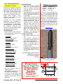
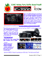
RF
ORANGE COUNTY AMATEUR RADIO CLUB, INC.
VOL. XLVI NO. 12
P.O. BOX 3454, TUSTIN, CA 92781-3454
de: Ken Konechy, W6HHC
The club Christmas Dinner is
coming up soon
on Friday, Dec
16, at the Jagerhaus on Ball
Road in Anaheim. Dan N6PEQ and Kristin
K6PEQ have arranged for a SUPER RAFFLE at the dinner party.
The main prize is an ICOM-7000
rig!!! You must be present to win.
From my view as Prez in 2005, I
think that the OCARC did very
well this year. We grew our membership, had great presentations
at meetings, had fun events like
Field Day and a club Potluck, and
participated in community service
events like helping local police departments in the Baker-2-Vegas
race. A radio club is only successful because members pitch-in to
make it a fun club. So, I would
like to thank the board members
for pitching-in.
Thanks Willie-N8WP for making
sure we had good programs, offering to be one of the “rotating editors” for the newsletter, and being
our FD organizer – great location
and great steaks.
Thanks Rich-KE6WWK for capturing our club minutes, for getting
OCARC recognized as an ARRL
Special Services Club, and talking
so many club members in to helping at the B2V race through COAR.
Thanks Cheryl-KG6KTT for keeping the club finances so well organized and so well reported and for
organizing our December Dinner.
Thanks to Kristin-K6PEQ for obtaining those great monthly raffle
prizes, for encouraging me to buy
more raffle tickets, for organizing
the club Potluck event, for being an
extraordinary “rotating” editor of
the club magazine, and representing OCARC at the OCCARO meetings.
Thanks Dan-N6PEQ for pitching in
when the Membership position
needed some help, for sending out
nice invitation flyers to prospective
members, for being such a good
BBQ chef at the Potluck, and for
smooth talking so many donations
for our Christmas Dinner raffle.
Thanks to Kenaan-N6CCE for storing the club’s equipment, writing
great RF articles, volunteering to
be a newsletter “rotating” editor,
and being such a “top gun” band
captain at Field Day.
Thanks to Bob-AF6C for helping to
launch the great “rotating editor”
program for the newsletter this
year, for designing a great OCARC
advertising poster to place at HRO,
for designing the outstanding trifold flyer to advertise the club at
HRO and the OC Fair, for being
our craftsman badge maker, and
for running the 10M/15M weekly
net for many, many years.
And I want to thank our two Directors-at-Large this year, LowellKQ6JD and Steve-N1AB, who
made my job much easier by taking
on every task that I threw their
way...you guys really helped me.
See you at the Christmas Dinner!
Details inside!
DECEMBER 2005
There will be no regular December
meeting. Instead the club will hold
its December Christmas Dinner
on the 16th, which by coincidence
is a third Friday meeting date..
The Dinner will be at Jagerhaüs in
Anaheim. See pages 10 and 11 for
a map and more details, Contact
our Treasurer for tickets.
Don’t miss it.! It’s going to be an
extravaganza – dinner and raffle!
The next regular meeting will be:
Friday, Jan. 20th 2006
@ 7:00 PM
We will be meeting on the 2nd
floor in the east bldg.
In This Issue:
Page
THE PREZ SEZ ..................... 1
NO DECEMBER MEETING ..... 1
CLUB INFORMATION ............. 2
30 MTR ANTENNA Pt. III ......... 3
PRODUCT SPOTLIGHT
JRC NRD-545 Receiver ........ 4
CLUB E-VOTE ....................... 8
Errata: MEETING ADDRESS ....9
SPECIAL THANKS ................ 8
YAESU JOB OPENING ........... 9
FCC ACTION: 147.435 R ........ 9
NOV. MEETING MINUTES .... 10
HOLIDAY DINNER MAP ... 10
DINNER RAFFLE PRIZES .... 11
DEC. BOARD MINUTES ....... 12
Next Club Breakfast &
Open Board Meeting
Sat. Jan. 7th 2006
THE ORANGE COUNTY
AMATEUR RADIO CLUB,
INC.
P.O. Box 3454, Tustin, CA 92781
Technical:
Kenan Reilly, N6CCE
(714) 543-5073
[email protected]
Members At Large:
Steve Brody, N1AB
(714) 974-0338
[email protected]
Lowell Burnett, KQ6JD
(714) 997-0999
[email protected]
2005 Club Appointments:
2005 Board of Directors:
President:
Ken Konechy, W6HHC
(714) 744-0217
[email protected]
Vice President:
Willie Peloquin, N8WP
(714) 318-4047
[email protected]
Secretary:
Rich Helmick, KE6WWK
(714) 343-4522
[email protected]
Treasurer:
Cheryl Peloquin, KG6KTT
(714) 318-4042
[email protected]
Membership:
Dan Dankert, N6PEQ
(714) 544-9846
[email protected]
Activities:
Kristin Dankert, K6PEQ
(714) 544-9846
[email protected]
Publicity:
Bob Eckweiler, AF6C
(714) 639-5074
[email protected]
December 2005 - RF Page 2
W6ZE Trustee:
Bob Eckweiler, AF6C
(714) 639-5074
[email protected]
Club Historian:
Bob Evans, WB6IXN
(714) 543-9111
[email protected]
RF Editor for December:
Bob Eckweiler, AF6C
(714) 639-5074
[email protected]
WEB Master:
Ken Konechy, W6HHC
(714) 744-0217
[email protected]
ARRL Assistant Director:
Ken Konechy, W6HHC
(714) 744-0217
[email protected]
ARRL Awards Appointee:
Larry Beilin, K6VDP
(714) 557-7217
[email protected]
OCCARO Delegate:
Kristin Dankert, K6PEQ
(714) 544-9846
[email protected]
Monthly Events:
General Meeting:
Third Friday of the Month
At 7:00 PM
American Red Cross
600 Parkcenter Dr.
(near Tustin Ave. & 4th St)
Santa Ana, CA
Club Breakfast:
First Saturday of the
month at 7:30 AM
Katella Grill
1325 W. Katella Ave.
(SE Corner at Main St.)
Orange, CA
Club Nets (Listen for W6ZE):
7.086 MHz CW OCWN
Sun - 9:00 AM - 10:00 AM
Rick KF6UEB, Net Cntl.
28.375± MHz SSB
Wed - 7:30 PM - 8:30 PM
Bob AF6C, Net Control
146.55 MHz Simplex FM
Wed - 8:30 PM - 9:30 PM
Bob, WB6IXN, Net Control
VISIT OUR WEB SITE
http://www.w6ze.org
for up-to-the-minute club
information, the latest
membership rosters, special activities, back issues
of RF, links to ham-related
sites, vendors and manufacturers, pictures of club
events and much much
more.
Club Dues:
Regular Members ...... $20
Family Members* ...... $10
Teenage Members ...... $10
Club Badge** ................ $3
Dues run from January thru December
& are prorated for new members.
*Additional members in the family of
a regular member pay the family
rate up to $30 per family.
**There is a $1 charge if you’d like to
have your badge mailed to you.
Techtalk #46
A Shortened 30M Dipole – Part III of III
“How It Actually Performs”
by Ken Konechy – W6HHC
In the Part I (March 2005 issue of RF) of this series, I
walked thru the steps of designing a “shortened 30M
vertical” antenna using the knowledge from the WinNEC antenna modeling program-and-class offered by
the ARRL. In Part II (November 2005 issue), I showed
how to build/construct the 30M antenna from aluminum tubing, some PVC piping and do-it-yourself loading coils. In this months article of this three-part series, Part III discusses actually tuning-up the antenna,
comparing SWR readings, and on-the-air QSO results.
In the Part II I had shown a drawing of how to construct a simple “tower” for the 30M antenna using a
10-foot section of 2x4 lumber. In Figure 1, I show how
the completed 30M antenna and tower look in my
backyard. The entire length of the 30M antenna is
just over 11 feet and the center of the antenna is
shown at 10 Feet. I used a 1:1 balun (made by Van
Gordon) that I bought at the recent club auction to
feed coax to the balanced antenna at the feedpoints.
If you don’t use a balanced balun, then ensure that
the ground side of the coax feeds the bottom side of
the vertical.
In Figure 2, I show the SWR predicted by NEC-Win
antenna modeling program for the 11-foot, 1-inch overall length of the 30M antenna. The “real world” always varies from perfect models – probably variation
of inductance in my hand-wound 16.5 uH loading
coils. Figure 3 shows that actual SWR measurement
that I first obtained. So I could either tweak the coils
(could be very labor consuming) – or I could use the
computer to tell me how much to adjust the length of
the antenna. The darker line in Figure 3 shows that
the resonant frequency is higher than desired (around
10.185 MHz instead of the desired 10.125 MHz) – so
by lengthening the antenna I can adjust the resonance down to exactly where I want it.
VSWR vs. Frequency
2.9
30M-short vert-dipole 11-ft-1-inch
V 2.8
S 2.7
W
R 2.6
2.5
10.10
10.11
10.12
10.13
Frequency MHz
10.14
10.15
Figure 2 – NEC-Win Predicted SWR for
11-foot-1-inch Antenna
2.2
Actual VSWR Measurements
2.0
V 1.8
S
W 1.6
R 1.4
1.2
1.0
10.10
Len = 11’ 1”
Len = 11’ 3”
10.12
10.14
10.16
10.18
Frequency MHz
Figure 3
I played with the antenna length on the NEC-Win
computer program and found that if I change the
length on the two outer pieces of aluminum so that
the overall length was 11-foot-3-inches (add one inch
to each end), then the resonance would shift down
by 60 KHz. The lighter line in Figure 3 shows the actual SWR measurements after adjusting the antenna
length to 11-foot-3-inch. Almost perfect – certainly
good enough to use. I should have made it 11-foot3.5-inch. Figure 4 shows a close-up detail of how I added the 1-inch wire to the ends of the element. Just
some 14-guage solid copper wire, a solder lug, and a
stainless steel 1/4-inch bolt.
Figure 1 – 30M Shortened Dipole Mounted
as a Vertical on Simple Tower
So, it is now time to make a contact!!! Learning CW
again after many years takes a few days of practice.
The 30M band is just CW and digital PSK-31 data.
So I went slowly – but here is a list of my first four
QSOs on 30M.
See Antenna - on Page 10
December 2005 - RF Page 3
*** Product Spotlight ***
Japan Radio Company (JRC) Model NRD-545
HF/VHF/UHF DSP Receiver
By: Dan Dankert N6PEQ
[email protected]
I recently found myself in the marketplace for an all-mode receiver with wide-band frequency coverage. My frequency range of interest was 0 MHz thru 2000 MHz. There is not a wide selection of
radios currently available to the average consumer for this entire frequency range. Typically you
either purchase a new receiver, such as AOR’s model AR3000 or AR5000, or Yaesu’s model VR-5000. Used receivers that fit the bill are Icom’s IC-R8500 and IC-R9000L. It turned out that there was one other option. This
is the Japan Radio Company (JRC) model NRD-545 DSP receiver. This receiver comes standard with all-mode
capability covering 0.1 MHZ to 29.9999 MHz. An optional wide-band receive board (CHE-199) is available
which extends the all-mode frequency coverage up to 1999.9999 MHz. I had not previously owned a piece of
JRC equipment, but I was aware of their legendary performance. JRC receivers are used quite extensively by
ship-board radio operators because of their impressive receiver characteristics and non-fatiguing audio quality.
The table below indicates some of the specifications for the NRD-545 receiver. After a detailed review of the
NRD-545 literature, and a few phone calls to some friends knowledgeable in high-end receivers, the decision
was made to purchase the NRD-545. After a quick email to HRO, my new receiver was on its way from JRC
America, soon to arrive at my home QTH. Eagerly awaiting the arrival of the unit, I wired up a few cables
ahead of time, so that I would minimize setup time. Once the JRC package was delivered, it took only a short
duration to get it fired up. There’s nothing quite like the smell of a new piece of radio equipment. Time to play!
Japan Radio Company (JRC) Model NRD-545 Manufacturers Specifications
0.01 to 29.9999 MHz
(0.01 to <0.1 MHz Specifications Not Guaranteed)
Frequency Coverage
0.01 to 1999.9999 MHz (Less Cellular) with Optional CHE-199
Wide-Band Converter Board Installed
USB, LSB, CW, RTTY, AM, FM
Reception Modes
WFM (With Optional CHE-199 Installed)
± <10 ppm (5 to 60 minutes after Power Up)
Frequency Stability
± 2 ppm (>60 Minutes after Power Up)
± <0.5 ppm (with Optional CGD-197 TCXO Installed)
Triple Conversion Superheterodyne
>70 dB Image Rejection
Receiver
>60 dB Spurious Response
>70 dB IF Rejection
106 dB Dynamic Range (300 Hz IF Bandwidth)
13” W x 5.62”H x 12.9”D
Size/Weight
16.5 lbs (Without Options)
Power Requirements
12 to 16 VDC or 100/120/220/240 VAC
0.2 to 29.9999 MHz: 50 Ohm “UHF” Female Jack
Antenna Connectors
& 600 Ohm Wire terminal
30 to 1999.9999 MHz: 50 Ohm “N” Female Jack
Front Panel Ergonomics... The
front panel of the radio, pictured below, has a clean layout with wellspaced buttons and knobs. There is
no over use of real estate happening
here! The display is bright, and has a
large and easy to read frequency readout. The digital bar graph S-meter
features a peak hold function. The
tuning knob is solid and has a nice
feel to it. Direct keyboard entry of frequency makes for quick QSYing. There
are buttons for three user adjustable
filter settings. Other “typical” controls
are found such as tone, AF gain, RF
gain, squelch, notch filter, mode selection, clock, timer, dimmer, attenuator,
scan functions and frequency lock.
Front Panel
View
December 2005 - RF Page 4
“Cool” Features...
• The NRD-545 features DSP noise reduction. The level of the noise reduction aggressiveness is selectable via a menu function. There are 256 different levels of noise reduction available to choose from. The DSP is accomplished using a one-chip DSP shown in the picture to the right.
• A beat canceler is also provided, which is adjustable among 256 different
settings via a menu function.
• In addition to the standard “AM” reception mode, the NRD-545 offers a
“AMS” mode. The “AMS” mode is a high-fidelity (Hi-Fi) version of AM reception.
• Not only is a notch feature available, but also offered is a “notch tracking”
DSP Chip
mode! You press the notch button to activate the notch circuitry, then using
the adjustment knob, you manually notch out the carrier that you desire to eliminate. Then you press
the notch button again. This places the notch into “tracking” mode. The notch will then continuously
track the specific carrier that you notched, as you tune the main tuning dial within +/- 10 KHz from the
start frequency. Neat feature!
• A very advantageous feature of the NRD-545 is the “ECSS” mode. ECSS stands for “Exhalted Carrier
Selectable Sideband”. If you listen to an AM signal that is exhibiting signal distortion due to signal fading, you would engage the ECSS mode to counteract the band conditions that are resulting in the signal
fading. In standard AM transmissions, double sideband (DSB) is used, in which the modulated signal
is transmitted in both upper sideband (USB) and lower sideband (LSB). In the ECSS mode, you listen
to the AM signal in a single sideband (SSB) configuration. By pressing the “ECSS” button, you toggle
between utilizing the USB or LSB component of the modulated AM signal for listening, while providing
a locked carrier signal. This reduces audio distortion and fading, since in many cases only the USB or
LSB side of the AM signal is being primarily affected by the phenomena, which is called “selective
fading”.
• Numerous tuning steps are available including 1 Hz, thanks to a one-chip DDS (Digital Direct Synthesizer). The 1 Hz tuning is especially helpful in tuning PSK and RTTY signals. The entire selection of
available tuning steps is 1 Hz, 10 Hz, 100 Hz, 1 KHz, 5 KHz, 6,25 KHz, 9 KHz (Nice for foreign MW
BCB DXing), 10 KHz, 12.5 KHz, 20 KHz, 25 KHz, 30 KHz, 50 KHz & 100 KHz.
• In the USB, LSB, CW & RTTY modes, the AGC discharge time is continuously adjustable between 0.04
seconds to 5.1 seconds in 20 millisecond increments.
• Pass-Band Shift (PBS) is variable within the range of +/- 2.3KHz on 50 Hz steps. This simply shifts the
digital IF filter upward or downward to reduce interference from adjacent frequencies.
• Pass-Band filtering is adjustable from 10 Hz to 9.99 KHz in 10 Hz increments. Each of the three user
adjustable filters can be individually set to the pass-band filter width of your preference.
• A RTTY demodulator is built into the receiver. The demodulator deciphers RTTY signals with widths of
170 Hz, 425 Hz or 850 Hz, and with rates ranging from 37 to 75 baud. The demodulated signals can
be displayed through the use of a computer utilizing the RS-232C port on the rear panel of the NRD545.
• The tuning knob has a handy torque adjustment. The torque adjustment control is conveniently located
directly underneath the tuning knob making for swift altering.
Rear Panel
View
December 2005 - RF Page 5
Rear Panel Connections... Pictured on the previous page is the rear panel of the NRD-545 receiver. The
“typical” types of connections are available, such as 13.8 Vdc power input, 100/120/220/240 Vac power input,
external speaker output, timer relay output for automatically triggering a recording device, RS-232C port for
computer control and RTTY demodulation display, “UHF” type antenna input for HF, “N” type antenna input
for UHF/VHF (optional CHE-199 required), high impedance antenna input, a toggle switch for selection between the “UHF” or the high impedance antenna for the HF bands, ground terminal, “DC Out” jack (10.8 Vdc
output @ 30 mA), right and left line outputs for speakers and a mute jack for use in combination with a
transceiver/transmitter. I find the “DC Out” jack to be quite useful to activate my +15 dB preamplifier, which I
installed inline between the antenna and the NRD-545. The NRD-545 offers just enough current to power up
my preamplifier.
Internal Construction... The
inside of the NRD-545 is unique as
compared to most receivers. As you
can see from the picture to the right,
the NRD-545 features modular construction with plug-in P.C. boards on
its motherboard. This gives the inside of the radio a very simple yet attractive look. Since I purchased the
optional high-stability TCXO and wide-band receive board, the plug-in
boards made installation of these
items a breeze! JRC provides two
helpful lever tools to assist in removal of the internal P.C. boards.
Optional Accessories...
Pictured below left is the CHE-199
wide-band receive board. This is the
component that provides the receiver
with reception capabilities up to
Top View with Cover Removed
1999.999 MHz! The board is simply
plugged into the NRD-545’s motherboard. A small coaxial cable that is
already furnished inside of the NRD545’s chassis, is then plugged into a
female coax jack located on the
CHE–199 board. After the installation is complete, you must initialize
the radio by pressing the “CLR” button while powering up the NRD-545.
This is a one-time initialization to
activate the UHF/VHF reception capabilities.
Optional Wideband Receive Card
The installation of the CGD-197 high-stability TCXO (pictured at the
right) is a little more involved than that of the CHE-199. First, you remove the “REF/DDS” from the NRD-545 chassis. The CGD-197 TCXO is
then soldered onto this board in a pre-marked location. The REF/DDS
board is labeled very clearly, and the CGD-197 TCXO can only be orientated in one direction on the board. A small jumper located on the
REF/DDS board is then swapped between two rows of pins to actuate
the TCXO. The REF/DDS board is then reinstalled into the NRD-545
chassis. This completes the installation of the high-stability TCXO. The
December 2005 - RF Page 6
photo on the left shows the TCXO
mounted on the top-left quadrant of
the REF/DDS board right above the
green jumper.
REF/DSS Card with TCXO Installed
JRC NVA-319 Speaker
Pictured below left, the JRC NVA319 external speaker for the NRD545 offers three different audio response cuts, as well as inputs for
two separate radios. The NVA-319
has nice audio quality. The speaker
matches the height, color and finish
of the NRD-545 receiver. As with
any high-end receiver, an external
speaker is essential in order to capitalize on the exceptional receiver
characteristics and cutting edge
features of the NRD-545.
At the time of my purchase, the NRD545 came supplied with the JRC
model ST-3 headphones. Pictured to
the right, The ST-3 has a good solid
feel to them, while at the same time
remaining quite lightweight. The audio has good fidelity and tone quality.
The cable coming from the headphones is of a larger diameter than
that of most other consumer grade
headphones, which should result in
longer cable life after years of excessive flexing.
NRD-545 Headphones
On The Air Performance... So does the radio perform? Yes! The receiving performance proved to be excellent. The receiver is sensitive and quiet. The DSP filter aggressively attacks noise, while at the same time enhancing signal quality. With the NRD-545’s DSP capability, it is routine to convert a signal that is scarcely distinguishable to one of full readability. The world of DSP is fantastic! If you have not yet taken advantage of this
leap in technology, you are missing out! The pass-band shift feature does an excellent job of eliminating unwanted signals. The ability to adjust the filter bandwidth as tight as 10 Hz really is very beneficial. Although
significantly effective in AM, SSB & RTTY modes, I found this feature to be especially useful while receiving CW
signals in close proximity to one other. The noise blanker is adequate, and it has typical performance as compared to most other radios. The notch filter provides for a very sharp and deep null of a heterodyne. The notchtracking feature works great! I found it very advantageous to be able to notch a specific heterodyne, and still be
able to tune the main dial somewhat without the necessity of readjusting the notch filter. The receiver’s selectivity is outstanding. Of the numerous radios that I have operated over the years, the NRD-545 is one of best
radios at reducing or eliminating interference from an exceedingly strong adjacent signal. The radio accomplishes this with minimal work from the operator. A quick press of a button or two, and a few turns of a knob or
two, and presto! I found the audio quality to be very clean and full. The audio is easy on the ears, even after
hours of constant listening. The “AMS” (Hi-Fi) mode has an extraordinarily nice sound to it. Another feature,
which created a more pleasing listening environment, is the exhalted carrier selectable sideband “ECSS” mode.
This mode really works nicely! Most SWBC signals, that I found experiencing selective fading, were vastly improved by using the ECSS mode. During selective fading, the signal’s audio can become distorted and
sometimes be very harsh on the ears. With a push of the “ECSS” button, the received audio is significantly enhanced. I found myself using this feature constantly, and my ears benefited from the more pleasant sound. I do
not know how I lived without it! This is one the highlights of this radio. I was grateful for the well thought out
design of the main tuning knob. The knob’s torque adjustment allows for a proper feel of tuning control under
varying operating conditions. My hand did not suffer from fatigue due to the positioning of the dial. In fact, all of
the knobs and buttons tended to have a solid “quality” feel to them. For the most part, the layout of the radio’s
front panel made for quick access of functions. With the buttons and controls well spaced, there is no need to
call out a search party to locate a specific function. In order to initiate reception from 10 KHz to <100 KHz, you
December 2005 - RF Page 7
must press the “ENT/KHz button
while powering up the radio. In order to activate USB/LSB/CW/RTTY
modes above 30 MHz, you must
press
the
“USB/LSB”
and
“CW/RTTY” buttons while powering up the NRD-545. In both of the
cases, JRC does not guarantee the
receiver specifications for these additional features added by these
modifications. I found the SSB and
CW modes to work well in the
VHF/UHF spectrum.
Odds & Ends... The NRD-545
has the ability to be computer controlled.
This is accomplished
B
through the RS-232C port on the
rear panel. JRC offers a simple “no
frills” Windows based program to
get you started in controlling the
radio with your computer. In addition to controlling the basic
features of the radio, the software
also allows you to display decoded
RTTY signals on your computer
screen using the NRD-545’s built in
RTTY demodulator. The instruction manual for the radio provides
additional information on the commands used to operate the radio
via computer. I did not attempt
computer control of the radio, nor
did I execute the software. The
NRD-545 has the ability to store
up to 1,000 memories. Each memory saves the frequency as well as
mode, IF bandwidth, AGC setting,
attenuator setting, and tuning step
increment. The first 20 memories
also can store on/off times for the
internal timer and timer relay output.
Conclusion... I found myself
truly appreciating the NRD-545’s
advanced features and capabilities.
The receiver performance is excellent. The ability to eliminate band
noise and adjacent frequency interference while retaining signal integrity of the target signal is superb.
I enjoyed the simplicity of the front
panel controls, which resulted in efficient tuning. After significant
scrutiny, I was unable to discover
any defects in the receiver. The construction of the radio is robust and
sturdy. I expect to experience many
December 2005 - RF Page 8
years of pleasurable radio listening
with the NRD-545. There are only
a few specific items that I would
change:
• First, the manual should be
written in better English, and
also provide better detail of the
use of specific functions.
• The surface-finish of the front
panel buttons look attractive,
but they tend to overly reveal
the oils deposited by fingertips.
• I would like to see the DSP
noise reduction and beat canceler to be adjustable via a knob
on the front panel of the radio
rather than through a less convenient menu system.
• The “Fine Control”, which is
used to adjust the digital IF filter bandwidth and AGC discharge time constant, should be
“speed sensitive”. I found that
since the adjustment increment
is constant, that it sometimes
took much longer than it should
to tweak in the adjustment to
your preference. If this knob
could sense that you were turning the knob fast, and in turn
SPECIAL CLUB VOTE:
In a new first for the club, President Ken - W6HHC held the first
Board vote over the Internet. The
Board e-voted unanimously to authorize $300 in prize money for the
Christmas Dinner raffle. This
money is in addition to the many
donated prizes that Dan - N6PEQ
and Kristin - K6PEQ have arranged.
Errata:
CLUB MEETING ADDRESS:
For the past few years we have
been giving the address of the Red
Cross Building where we hold the
meetings as 601 N. Golden Circle.
Actually this is the west bldg,
where we did meet occasionally.
The address of the building where
we meet regularly is 600 Parkcenter.
A BIG CLUB THANK YOU…
…to the following businesses for
supporting and donating prizes to
our club. Please support these fine
increase the adjustment increment based upon this, it would
result more proficient operating.
If you happen to be in the market
for a receiver with high-end performance for the HF or HF/VHF/UHF
frequency spectrums, I would recommend considering the JRC NRD545 receiver. The NRD-545 is a formidable candidate for the task!
Manufacturer Information...
More information on the JRC NRD545 DSP receiver can be obtained
by contacting:
Japan Radio Company, Ltd.
2125 Center Avenue, Suite 208
Fort Lee, New Jersey 07024
Tel: 201-242-1882
Fax: 201-242-1885
Website:
http://www.jrc.co.jp
Street Price: NRD-545 DSP Receiver ($1800), NVA-319 External
Speaker ($200), CHE-199 VHF/
UHF Wide-Band Converter ($370),
CGD-197 High Stability TCXO
($100), ST-3 Headphones ($70),
6ZCJD090350 RS-232C Cable
($60), and Service Manual ($30).
companies with your purchases.
Look for additional supporters in
next month’s issue!
Career Opportunity: Vertex
Standard USA, Inc. (YAESU)
Job Title:
WDXC Program Manager
(WDXC: “World DXers Club,” –
a Customer Loyalty program)
Reporting To: Vice President
Job Start:
Immediately
Job Basis:
Full-time
Chief Responsibilities:
You will be responsible for supervising the WDXC program at Vertex Standard USA. This is a new
customer-loyalty
program
that
builds long-term sales through a
value-added partnership with current and potential customers.
WDXC responsibilities include, but
may not be limited to:
• Overseeing the growth and
maintenance of the WDXC membership;
• Overseeing the WDXC Web Site,
and coordinating with other departments and our Web designer
in the promulgation and maintenance of timely articles, news
FCC LIFTS PRIVILEGES OF
LA-AREA 147.435 REPEATER
The FCC alleges that problems
persist on the Los Angeles area's
147.435 MHz repeater, now operated by Jeffrey Stieglitz, AE6NZ.
The FCC Los Angeles District Office recently informed Stieglitz that
it was suspending automatic control privileges for the repeater.
That means the licensee or a designated control operator must be at
the repeater's control point whenever the machine is operational.
"Your amateur station AE6NZ is
under review by the Enforcement
Bureau for numerous and continued apparent violations of the
Commissions rules," FCC LA Office
District Director Catherine Deaton
wrote Stieglitz November 18. The
Commission alleges inadequate
station control, deliberate interference, failure of users to identify and
use by unlicensed operators.
Stieglitz told ARRL he encourages
updates, and support issues;
• Overseeing and supervising the
final assembly and testing of
products (such as the FT DX
9000) being assembled under
WDXC auspices;
• Overseeing the WDXC Auction
Site operations, including coordination and supervision of the efficient flow of paperwork related
to the inspection, repair, and certification of previously-owned
YAESU equipment;
• Coordinating promotional materials and activities related to
WDXC;
• Attendance at such trade shows
as management may deem appropriate and necessary for the
advancement and expansion of
WDXC and the YAESU product;
• Reporting to management, on a
regular basis, regarding WDXC
status, problems, and opportunities.
General:
and broad HF transceiver knowledge. Strong English writing and
communications skills are a must,
and foreign language capability
(especially Spanish) is definitely a
plus. Computer experience is mandatory, and knowledge of Amateur
Radio computer-based operations
(logging software, HF Packet/
RTTY, PSK31) is also desirable.
Vertex Standard USA, Inc. offers a
competitive compensation and benefits package, including a 401(k)
plan, medical and dental insurance, and a generous vacation
schedule.
If you would like to be considered
for this exciting position, please
send your resume to
Vertex Standard USA, Inc.
Attn. Mr. Jeff Quan,
Chief Financial Officer,
10900 Walker Street,
Cypress, CA 90630.
Fax: (714) 527-1494.
An Advanced or Extra Class Amateur Radio license is required, as
are current active DX experience
No telephone inquiries accepted.
See the WDXC Web site at
users of the busy repeater to comply with Part 97 rules and to make
a reasonable effort to identify unlicensed operators. "I believe that
the 147.435 repeater attracts people to the hobby and, overall, is
consistent with the purposes of
Amateur Radio," he said.
FCC terminated the automatic
control privileges of the thenW6NUT repeater while it was reviewing its operation. Since then
the repeater has changed hands a
few times, and enforcement issues
seem to have followed.
Deaton says if AE6NZ is operated
under automatic control prior to
notification from her office, enforcement action up to and including a
license revocation and suspension
hearing, a fine or both could follow.
Deaton also asked Stieglitz to submit in advance the names and contact numbers of other licensees
who serve as control operators.
"During any times that no control
operator is available, the repeater
must be shut down," Deaton
stated.
The odd-split 147.435 MHz repeater (the primary input is
146.400 MHz) has been a lightning
rod for controversy. In 2001, the
http://wdxc.yaesu.com
"As the Jack Gerritsen case shows,
there is very little the FCC can actually do against a determined
bootlegger," Stieglitz said. Gerritsen is set to appear in federal court
next week. "In my opinion, shutting down a repeater because a
third party breaks the rules just
penalizes the honest operators."
FCC Enforcement Bureau Special
Counsel Riley Hollingsworth had
another perspective: "The repeater
has been out of control long
enough, and we have been too patient too long," he told ARRL.
Excerpt from The ARRL Letter,
December 2nd.
December 2005 - RF Page 9
NOV. MEETING MINUTES
November 18, 2005
President Ken, W6HHC, called the
group to order at 7:00 PM. Roll call
was taken. Kenan, N6CCE, was
out of town, all others were present. There were 26 present with
visitors Fred, K6RMX; Steve, KI6ATO; Matt, KI6BLY; Vlad,
KI6BLP, Frank, WF1A; and new
member Paul, KQ6EH.
President Ken then introduced
Taka-KW6I and Jeff-AA6JR of
AOR-USA who gave a very interesting presentation on “New Digital
Voice Modulation”. After the break
the
meeting
continued.
The
minutes of the last board meeting
were approved as published.
NEW BUSINESS:
• Bob, AF6C (trustee of W6ZE)
asked for and was given a
name of someone who would
print the club QSL cards for a
reasonable price.
• Those gathered were reminded
that the Club board meets on
the first Saturday of the month
for breakfast.
• Newly elected President Willie
asked for information from the
visitors regarding what they expected from the club. They responded, advice on equipment,
advice on how to get into an
emergency response group, advice on how to set up mobile operations equipment, getting together with hams who like to
work on projects and test
equipment, and learning the
new techniques of ham radio.
Antenna – Cont. from Page 3
•
•
•
•
W5HZA
WA3SLN
AA5EA
KQØA
- Lafayette, LA
- Montourville, PA
- El Paso, TX
- Taos, NM
So this was a very successful project. I am very satisfied with the
results. I am active on 30M, now.
Dan-N6PEQ is advising me on the
“how to DX” characteristics of the
30M band. I have already heard a
KH6 and JA7. Perhaps I could organize a club antenna building projects if other club members are interested?? Contact me if you are
interested or have question on this
project at:
[email protected]
OLD BUSINESS:
• Board elections were held and
the following were elected to be
GOOD of the CLUB:
on the 2006 board:
• Dan, N6PEQ reported on recent
President:
DX..
Willie Peloquin, N8WP;
• Tom, WA6PFA, reported that
he has been monitoring SS ATV
Vice President:
and receiving good pictures.
Kristin Dankert, K6PEQ;
• Bob, AF6C reported that This
Secretary:
Week in Technology had a reSteve Brody, N1AB;
port on how good the Heil microphone sounds.
Treasurer:
•
President Ken reported that he
Cheryl Peloquin, KC6KTT;
will follow up in a future RF on
Activities Chair:
the 30 meter dipole he is conDan Dankert, N6PEQ;
structing.
Membership Chair:
The meeting adjourned at 9:07 PM.
Bob Eckweiler, AF6C;
Respectfully Submitted
Publicity Chair:
Rich Helmick KE6WWK
Tom Weed, K6CCD;
Secretary
Technical Chair:
Kenan Reilly, N6CCE;
Figure 4 – Close-up for Adding
1-inch wire to each end
Member at Large:
Lowell Burnett KQ6JD;
Member at Large:
Ken Konechy, W6HHC;
• All were thanked for their willingness to serve.
• Willie-N8WP explained the club
Christmas dinner (Dec 16).
• A review and discussion was
held before a final collection of
donations for the ARRL BPL defense fund.
December 2005 - RF Page 10
Dec 16th, 7 PM at the
2525 E Ball Road,
Anaheim, CA
(Note: Taft Ave. in Orange becomes
Ball Rd. in Anaheim)
December 2005 - RF Page 11
change membership-info flow as
follows:
1. The Treasurer will alert MemThe meeting was called to order by
bership when monies are rePresident Ken, W6HHC. Roll call
ceived and transfer over all newwas taken and all Board members
member info; and then…
were present except Bob, AF6C who 2. Membership will send out memwas ill. There were 15 members
bership-info to all requiring club
present at the meeting. Cherylfunctions.
KG6KTT reported that 33 tickets
OLD BUSINESS: Christmas dinto the Christmas party have been
ner set up is going well. The elecsold. Treasurer Cheryl, KC6KTT,
tion results from last general meetreported that the club has
ing will be in the RF. The club sent
$2,738.36 in the bank. Membera check for $396.00 to ARRL for
ship Chair Dan, N6PEQ, reported
BPL defense fund.
that the club has approximately 55
members. The board agreed to NEW BUSINESS: An audit committee of Larry Hoffman, Kristin
Dankert and Treasurer Cheryl will
meet in the middle of January
2006 to audit the club accounts.
President Ken has the name of the
recipient of the Good of the Club
award which will be given at the
Christmas dinner. A discussion
was held regarding opening a Pay
Pal account for club use. Willie,
N8WP, moved that the club open a
Next RF Deadline: Jan 9th
Pay Pal account and it was secondBoard Meeting Minutes
Dec. 3, 2005
ORANGE COUNTY AMATEUR RADIO CLUB, INC
P.O. BOX 3454
TUSTIN, CA 92781-3454
First Class Mail
Time Dated Material.
Please Expedite!!
December 2005 - RF Page 12
ed by Dan Dankert. The motion
passed on a voice vote. Kristin,
who is president of OCCARO, suggested dates for the club to be at
the OC Fair ham booth. The
agreed-upon dates are July 12 and
July 29. The club will “showcase”
DX on one of the days. Steve N1AB
suggested that the club have some
younger hams in the booth this
year. Willie reported that a field
day committee meeting will be
held in January.
The meeting adjourned at 8:20 AM.
Note: An e-vote was held to authorize monies for the Dinner Raffle. See page 8 for details
Respectfully Submitted
Rich Helmick KE6WWK
Secretary
With assistance from
Lowell KQ6JD