1
GE Oil & Gas
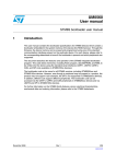
19000 Series
Consolidated* Safety Relief Valve
Maintenance Manual
GE Data Classification : Public
THESE INSTRUCTIONS PROVIDE THE CUSTOMER/OPERATOR WITH IMPORTANT PROJECT-SPECIFIC REFERENCE INFORMATION IN ADDITION
TO THE CUSTOMER/OPERATOR’S NORMAL OPERATION AND MAINTENANCE PROCEDURES. SINCE OPERATION AND MAINTENANCE
PHILOSOPHIES VARY, GE (GENERAL ELECTRIC COMPANY AND ITS SUBSIDIARIES AND AFFILIATES) DOES NOT ATTEMPT TO DICTATE
SPECIFIC PROCEDURES, BUT TO PROVIDE BASIC LIMITATIONS AND REQUIREMENTS CREATED BY THE TYPE OF EQUIPMENT PROVIDED.
THESE INSTRUCTIONS ASSUME THAT OPERATORS ALREADY HAVE A GENERAL UNDERSTANDING OF THE REQUIREMENTS FOR SAFE
OPERATION OF MECHANICAL AND ELECTRICAL EQUIPMENT IN POTENTIALLY HAZARDOUS ENVIRONMENTS. THEREFORE, THESE
INSTRUCTIONS SHOULD BE INTERPRETED AND APPLIED IN CONJUNCTION WITH THE SAFETY RULES AND REGULATIONS APPLICABLE AT
THE SITE AND THE PARTICULAR REQUIREMENTS FOR OPERATION OF OTHER EQUIPMENT AT THE SITE.
THESE INSTRUCTIONS DO NOT PURPORT TO COVER ALL DETAILS OR VARIATIONS IN EQUIPMENT NOR TO PROVIDE FOR EVERY POSSIBLE
CONTINGENCY TO BE MET IN CONNECTION WITH INSTALLATION, OPERATION OR MAINTENANCE. SHOULD FURTHER INFORMATION
BE DESIRED OR SHOULD PARTICULAR PROBLEMS ARISE WHICH ARE NOT COVERED SUFFICIENTLY FOR THE CUSTOMER/OPERATOR'S
PURPOSES THE MATTER SHOULD BE REFERRED TO GE.
THE RIGHTS, OBLIGATIONS AND LIABILITIES OF GE AND THE CUSTOMER/OPERATOR ARE STRICTLY LIMITED TO THOSE EXPRESSLY
PROVIDED IN THE CONTRACT RELATING TO THE SUPPLY OF THE EQUIPMENT. NO ADDITIONAL REPRESENTATIONS OR WARRANTIES BY GE
REGARDING THE EQUIPMENT OR ITS USE ARE GIVEN OR IMPLIED BY THE ISSUE OF THESE INSTRUCTIONS.
THESE INSTRUCTIONS ARE FURNISHED TO THE CUSTOMER/OPERATOR SOLELY TO ASSIST IN THE INSTALLATION, TESTING, OPERATION,
AND/OR MAINTENANCE OF THE EQUIPMENT DESCRIBED. THIS DOCUMENT SHALL NOT BE REPRODUCED IN WHOLE OR IN PART TO ANY
THIRD PARTY WITHOUT THE WRITTEN APPROVAL OF GE.
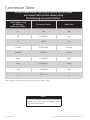
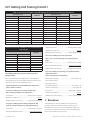
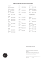
Conversion Table
All the United States Customary System (USCS) values
are converted to metric values using
the following conversion factors:
Metric values using
the following
conversion factors:
Conversion Factor
Metric Unit
in.
25.4
mm
lb.
0.4535924
kg
in2
6.4516
cm2
ft3/min
0.02831685
m3/min
gal/min
3.785412
L/min
lb/hr
0.4535924
kg/hr
psig
0.06894757
barg
ft lb
1.3558181
Nm
°F
5/9 (°F-32)
°C
Note: Multiply USCS value with conversion factor to get metric value.
NOTICE!
For valve configurations not listed in this manual,
please contact your local Consolidated* Green
Tag* Center for assistance.
2 | GE Oil & Gas
© 2015 General Electric Company. All rights reserved.
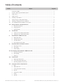
Table of Contents
Section
Subject
Page No
Conversion Table�������������������������������������������������������������������������������������������������������������������������������������������������������������������� 2
I.
Product Safety Sign and Label System ���������������������������������������������������������������������������������������������������������������������. 5
II.
Safety Alerts ���������������������������������������������������������������������������������������������������������������������������������������������������������������������������� 6
III.
Safety Notice���������������������������������������������������������������������������������������������������������������������������������������������������������������������������� 7
IV.
Warranty Information���������������������������������������������������������������������������������������������������������������������������������������������������������� 8
V.
Terminology for Safety Relief Valves����������������������������������������������������������������������������������������������������������������������������� 8
VI.
Handling, Storage, and Pre-Installation ���������������������������������������������������������������������������������������������������������������������� 9
VII.
Pre-Installation and Installation Instructions ���������������������������������������������������������������������������������������������������������� 10
VIII. Design Features and Nomenclature������������������������������������������������������������������������������������������������������������������������ 10
A. General Information��������������������������������������������������������������������������������������������������������������������������������������������������� 10
B. Design Options�������������������������������������������������������������������������������������������������������������������������������������������������������������� 10
C. Nomenclature���������������������������������������������������������������������������������������������������������������������������������������������������������������� 10
IX.
Introduction���������������������������������������������������������������������������������������������������������������������������������������������������������������������������� 11
A. 19000 MS & DA Safety Relief Valves�������������������������������������������������������������������������������������������������������������������� 11
B. 19096M-DA-BP Safety Relief Valves�������������������������������������������������������������������������������������������������������������������� 11
X.
Consolidated* 19000 Series SRV��������������������������������������������������������������������������������������������������������������������������������� 12
A
Metal Seat Valve������������������������������������������������������������������������������������������������������������������������������������������������������������ 12
B. Standard Cap Types���������������������������������������������������������������������������������������������������������������������������������������������������� 13
C. Soft Seat Valve��������������������������������������������������������������������������������������������������������������������������������������������������������������� 14
D. The 19096M-DA-BP Valve����������������������������������������������������������������������������������������������������������������������������������������� 15
XI.
Recommended Installation Practices��������������������������������������������������������������������������������������������������������������������� 16
A. Mounting Position ������������������������������������������������������������������������������������������������������������������������������������������������������ 16
B. Inlet Piping ��������������������������������������������������������������������������������������������������������������������������������������������������������������������� 16
C. Outlet Piping ����������������������������������������������������������������������������������������������������������������������������������������������������������������� 17
XII. Disassembly of Consolidated* 19000 Series SRV��������������������������������������������������������������������������������������������������� 18
A. General Information �������������������������������������������������������������������������������������������������������������������������������������������������� 18
B. Disassembly������������������������������������������������������������������������������������������������������������������������������������������������������������������� 19
C. Cleaning��������������������������������������������������������������������������������������������������������������������������������������������������������������������������� 19
XIII. Maintenance������������������������������������������������������������������������������������������������������������������������������������������������������������������������� 20
A. Metal Seat Valves (MS)������������������������������������������������������������������������������������������������������������������������������������������������ 20
B. O-Ring Seat Seal Valves (DA)����������������������������������������������������������������������������������������������������������������������������������� 25
C. Checking Spindle Concentricity ��������������������������������������������������������������������������������������������������������������������������� 26
XIV.
Inspection and Part Replacement����������������������������������������������������������������������������������������������������������������������������� 27
A. Base����������������������������������������������������������������������������������������������������������������������������������������������������������������������������������� 27
B. Metal Seat Disc������������������������������������������������������������������������������������������������������������������������������������������������������������� 27
C. O-Ring Seat Seal Assembly������������������������������������������������������������������������������������������������������������������������������������� 27
D. Bonnet������������������������������������������������������������������������������������������������������������������������������������������������������������������������������� 27
E. O-Ring Disc Holder������������������������������������������������������������������������������������������������������������������������������������������������������ 27
F.
Guide��������������������������������������������������������������������������������������������������������������������������������������������������������������������������������� 28
G. Spindle������������������������������������������������������������������������������������������������������������������������������������������������������������������������������ 28
© 2015 General Electric Company. All rights reserved.
Consolidated 19000 Series Safety Valve Maintenance Manual | 3
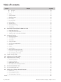
Table of Contents
Section
Subject
Page No
G.1
MS & DA ���������������������������������������������������������������������������������������������������������������������������������������������������������������������������� 28
G.2
DA - BP ������������������������������������������������������������������������������������������������������������������������������������������������������������������������������ 28
H. Spring�������������������������������������������������������������������������������������������������������������������������������������������������������������������������������������������� 29
I.
Spring Washers ����������������������������������������������������������������������������������������������������������������������������������������������������������������������� 29
J.
Adjusting Screw������������������������������������������������������������������������������������������������������������������������������������������������������������������������ 29
K. Bonnet Top���������������������������������������������������������������������������������������������������������������������������������������������������������������������������������� 29
L. Bonnet Bottom��������������������������������������������������������������������������������������������������������������������������������������������������������������������������� 30
M. Backup Plate������������������������������������������������������������������������������������������������������������������������������������������������������������������������������� 30
N. Spindle O-Ring���������������������������������������������������������������������������������������������������������������������������������������������������������������������������� 30
O. Backup Plate O-Ring��������������������������������������������������������������������������������������������������������������������������������������������������������������� 30
P.
XV.
Seat O-Ring���������������������������������������������������������������������������������������������������������������������������������������������������������������������������������� 30
Reassembly of Consolidated* 19000 Series SRV������������������������������������������������������������������������������������������������������������ 30
A. Metal Seat Valves (MS)������������������������������������������������������������������������������������������������������������������������������������������������������������ 30
B. O-Ring Seat Seal Valves (DA)����������������������������������������������������������������������������������������������������������������������������������������������� 31
C. 19096M-DA-BP O-Ring Seat Seal Valves����������������������������������������������������������������������������������������������������������������������� 31
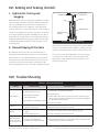
XVI. Setting and Testing������������������������������������������������������������������������������������������������������������������������������������������������������������������������� 33
A. General Information���������������������������������������������������������������������������������������������������������������������������������������������������������������� 33
B. Test Equipment�������������������������������������������������������������������������������������������������������������������������������������������������������������������������� 33
C. Test Media������������������������������������������������������������������������������������������������������������������������������������������������������������������������������������ 33
D. Setting the Valve����������������������������������������������������������������������������������������������������������������������������������������������������������������������� 33
E. Set Pressure Compensation������������������������������������������������������������������������������������������������������������������������������������������������ 33
F.
Blowdown������������������������������������������������������������������������������������������������������������������������������������������������������������������������������������� 34
G. Simmer������������������������������������������������������������������������������������������������������������������������������������������������������������������������������������������ 35
H. Seat Leakage������������������������������������������������������������������������������������������������������������������������������������������������������������������������������ 35
I.
Back Pressure Testing (MS & DA)��������������������������������������������������������������������������������������������������������������������������������������� 35
J.
Hydrostatic Testing and Gagging������������������������������������������������������������������������������������������������������������������������������������� 37
K. Manual Popping of the Valve��������������������������������������������������������������������������������������������������������������������������������������������� 37
XVII. Trouble Shooting Guide������������������������������������������������������������������������������������������������������������������������������������������������������������������ 37
XVIII. Maintenance Tools and Supplies����������������������������������������������������������������������������������������������������������������������������������������������� 38
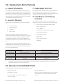
XIX. Replacement Parts Planning����������������������������������������������������������������������������������������������������������������������������������������������������� 39
A. General Information���������������������������������������������������������������������������������������������������������������������������������������������������������������� 39
B. Inventory Planning������������������������������������������������������������������������������������������������������������������������������������������������������������������� 39
C. Replacement Parts List���������������������������������������������������������������������������������������������������������������������������������������������������������� 39
D. Identification and Ordering Essentials���������������������������������������������������������������������������������������������������������������������������� 39
XX.
Genuine Consolidated* Parts�������������������������������������������������������������������������������������������������������������������������������������������������� 39
XXI.
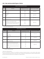
Recommended Spare Parts��������������������������������������������������������������������������������������������������������������������������������������������������������� 40
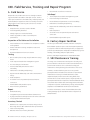
XXI. Field Service, Training, and Repair Program�������������������������������������������������������������������������������������������������������������������� 41
A. Field Service�������������������������������������������������������������������������������������������������������������������������������������������������������������������������������� 41
B. Factory Repair Facilities�������������������������������������������������������������������������������������������������������������������������������������������������������� 41
C. SRV Maintenance Training��������������������������������������������������������������������������������������������������������������������������������������������������� 41
Notes:������������������������������������������������������������������������������������������������������������������������������������������������������������������������������������������������������������������� 42
4 | GE Oil & Gas
© 2015 General Electric Company. All rights reserved.
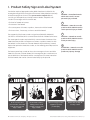
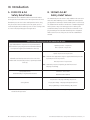
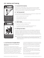
I. Product Safety Sign and Label System
If and when required, appropriate safety labels have been included in the
rectangular margin blocks throughout this manual. Safety labels are vertically
oriented rectangles as shown in the representative examples (below),
consisting of three panels encircled by a narrow border. The panels can
contain four messages which communicate:
• The level of hazard seriousness
• The consequence of human, or product, interaction with the hazard
• The instructions, if necessary, on how to avoid the hazard
The top panel of the format contains a signal word (DANGER, WARNING,
CAUTION or ATTENTION) which communicates the level of hazard seriousness.
The center panel contains a pictorial which communicates the nature of the
hazard, and the possible consequence of human or product interaction with
the hazard. In some instances of human hazards the pictorial may, instead,
depict what preventive measures to take, such as wearing personal protective
equipment.
The bottom panel may contain an instruction message on how to avoid the
hazard. In the case of human hazard, this message may also contain a more
precise definition of the hazard, and the consequences of human interaction
with the hazard, than can be communicated solely by the pictorial.
2
Do not remove bolts if
pressure in line, as this will
result in severe personal
injury or death.
DANGER — Immediate hazards
which WILL result in severe
personal injury or death.
2
• The nature of the hazard
1
1
WARNING — Hazards or unsafe
practices which COULD result in
severe personal injury or death.
3
CAUTION — Hazards or unsafe
practices which COULD result in
minor personal injury.
4
ATTENTION — Hazards or unsafe
practices which COULD result in
product or property damage
4
3
Know all valve exhaust/
leakage points to avoid
possible severe personal
injury or death.
© 2015 General Electric Company. All rights reserved.
Wear necessary protective
equipment to prevent
possible injury
Handle valve carefully. Do
not drop or strike.
Consolidated 19000 Series Safety Valve Maintenance Manual | 5
II. Safety Alerts
Read - Understand - Practice
•
Do not work or allow anyone under the influence of
intoxicants or narcotics to work on or around pressurized
systems. Workers under the influence of intoxicants or
narcotics are a hazard to themselves and other employees.
Actions taken by an intoxicated employee can result in
severe personal injury or death to themselves or others.
•
Always perform correct service and repair. Incorrect service
and repair can result in product or property damage or
severe personal injury or death.
•
Always use the correct tool for a job. The misuse of a tool
or the use of an improper tool can result in personal injury,
damage to product or property.
•
Ensure the proper “health physics” procedures are followed,
if applicable, before starting operation in a radioactive
environment.
Danger Alerts
A DANGER alert describes actions that may cause severe
personal injury or death. In addition, it may provide preventive
measures to avoid severe personal injury or death.
DANGER alerts are not all-inclusive. GE cannot know all
conceivable service methods nor evaluate all potential hazards.
Dangers include:
•
High temperature/pressure can cause injury. Ensure all
system pressure is absent before repairing or removing
valves.
•
Do not stand in front of a valve outlet when discharging.
STAND CLEAR OF VALVE to avoid exposure to trapped,
corrosive media.
•
•
•
Exercise extreme caution when inspecting a pressure relief
valve for leakage.
Allow the system to cool to room temperature before
cleaning, servicing, or repairing. Hot components or fluids
can cause severe personal injury or death.
Always read and comply with safety labels on all
containers. Do not remove or deface container labels.
Improper handling or misuse could result in severe personal
injury or death.
•
Never use pressurized fluids/gas/air to clean clothing or
body parts. Never use body parts to check for leaks, flow
rates, or areas. Pressurized fluids/gas/air injected into or
near the body can cause severe personal injury or death.
•
It is the owner’s responsibility to specify and p
rovide
personal protective wear to protect persons from
pressurized or heated parts. Contact with pressurized or
heated parts can result in severe personal injury or death.
6 | GE Oil & Gas
Caution Alerts
A CAUTION alert describes actions that may result in a personal
injury. In addition, they may describe preventive measures that
must be taken to avoid personal injury. Cautions include:
•
Heed all service manual warnings. Read installation
instructions before installing valve(s).
•
Wear hearing protection when testing or operating valves.
•
Wear appropriate eye and clothing protection.
•
Wear protective breathing apparatus to protect against
toxic materials.
© 2015 General Electric Company. All rights reserved.
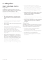
III. Safety Notice
Proper installation and start-up is essential to the safe and reliable operation of all valve
products. The relevant procedures recommended by GE, and described in these instructions,
are effective methods of performing the required tasks.
Wear necessary personal
protective equipment to
prevent possible injury
It is important to note that these instructions contain various “safety messages” which
should be carefully read in order to minimize the risk of personal injury, or the possibility that
improper procedures will be followed which may damage the involved GE product, or render
it unsafe. It is also important to understand that these “safety messages” are not exhaustive.
GE cannot possibly know, evaluate, and advise any customer of all of the conceivable ways
in which tasks might be performed, or of the possible hazardous consequences of each
way. Consequently, GE has not undertaken any such broad evaluation and, thus, anyone
who uses a procedure and/or tool, which is not recommended by GE, or deviates from GE
recommendations, must be thoroughly satisfied that neither personal safety, nor valve safety,
will be jeopardized by the method and/or tools selected. Contact GE at (318) 640-6055 if there
are any questions relative to tools/ methods.
The installation and start-up of valves and/or valve products may involve proximity to fluids
at extremely high pressure and/or temperature. Consequently, every precaution should
be taken to prevent injury to personnel during the performance of any procedure. These
precautions should consist of, but are not limited to, ear drum protection, eye protection,
and the use of protective clothing, (i.e., gloves, etc.) when personnel are in, or around, a
valve work area. Due to the various circumstances and conditions in which these operations
may be performed on GE products, and the possible hazardous consequences of each
way, GE cannot possibly evaluate all conditions that might injure personnel or equipment.
Nevertheless, GE does offer certain Safety Alerts, listed in Section II, for customer information
only.
It is the responsibility of the purchaser or user of Consolidated* valves/ equipment to
adequately train all personnel who will be working with the involved valves/equipment. For
more information on training schedules, call 318/640-6054. Further, prior to working with
the involved valves/equipment, personnel who are to perform such work should become
thoroughly familiar with the contents of these instructions. Additional copies of these
instructions can be purchased, at a minimal cost, by contacting GE (in writing) at P.O. Box
1430, Alexandria, LA 71309-1430, or by calling at 318/ 640-2250, Fax (318) 640-6325.
© 2015 General Electric Company. All rights reserved.
Consolidated 19000 Series Safety Valve Maintenance Manual | 7
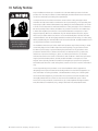
IV. Warranty Information
Warranty Statement: GE warrants that its products and work will meet all applicable
specifications and other specific product and work requirements (including those of
performance), if any, and will be free from defects in material and workmanship.
CAUTION: Defective and nonconforming items must be held for GE’s inspection and
returned to the manufacturer upon request.
Incorrect Selection or Misapplication of Products: GE cannot be responsible for customers’
incorrect selection or misapplication of our products.
Unauthorized Repair work: GE. has not authorized any non-GE- affiliated repair companies,
contractors or individuals to perform warranty repair service on new products or field repaired
products of its manufacture. Therefore, customers contracting such repair services from
unauthorized sources do so at their own risk.
Defective and
nonconforming items must
be inspected by GE
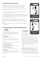
Unauthorized Removal of Seals: All new valves and valves repaired in the field by GE
Consolidated* Field Service are sealed to assure the customer of our guarantee against
defective workmanship. Unauthorized removal and/or breakage of this seal will negate our
warranty.
NOTE: Refer to GE’s Standard Terms of Sale for complete details on warranty and limitation of
remedy and liability.
SEA
LED
V. Terminology for Safety Relief Valves
(SRV)
1. Accumulation
The pressure increase over the maximum allowable working
pressure of the vessel during discharge through the SRV,
expressed as a percentage of that pressure or in actual
pressure units.
2. Backpressure
The pressure on the discharge side of the SRV:
a. Built-up Backpressure - the pressure that develops at the
valve outlet, after the SRV has been opened, as a result of
flow.
b. Superimposed Backpressure - the pressure in the discharge
header before the SRV is opened.
3. Constant Backpressure
The superimposed backpressure that is constant with time.
4. Variable Backpressure
The superimposed backpressure that varies with time.
5.
Blowdown
The difference between set pressure and re-seating pressure
of the SRV, expressed as a percentage of the set pressure or in
actual pressure units.
8 | GE Oil & Gas
6. C
old Differential
Set Pressure
Removal and/or breakage
of seal will negate our
warranty.
The pressure at which the
valve is adjusted to open
on the test stand. This pressure includes the corrections for
backpressure and/or temperature service conditions.
ifferential Between Operating and Set Pressures Valves- in
D
installed process services will generally give best results if
the operating pressure does not exceed 90 percent of the
set pressure. However, on pump and compressor discharge
lines, the differential required between the operating and set
pressures may be greater because of pressure pulsations
coming from a reciprocating piston. The valve should be set as
far above the operating pressure as possible.
7. Lift
The actual travel of the disc away from the closed position
when a valve is relieving.
8. Maximum Allowable Working Pressure The maximum gauge pressure permissible in a vessel at a
designated temperature. A vessel may not be operated above
this pressure, or its equivalent, at any metal temperature
other than that used in its design. Consequently, for that metal
© 2015 General Electric Company. All rights reserved.
V. Terminology for Safety Relief Valves (Contd.)
temperature, it is the highest pressure at which the primary
pressure SRV is set to open.
9. Operating Pressure
The gauge pressure to which the vessel is normally subjected
in service. A suitable margin is provided between operating
pressure and maximum allowable working pressure. For
assured safe operation, the operating pressure should be
at least 10 percent under the maximum allowable working
pressure or 5 psi (.34 bar), whichever is greater.
10. Overpressure
A pressure increase over the set pressure of the primary
relieving device. Overpressure is similar to accumulation when
the relieving device is set at the maximum allowable working
pressure of the vessel. Normally, overpressure is expressed as a
percentage of set pressure.
11. Rated Capacity
The percentage of measured flow at an authorized percent
overpressure permitted by the applicable code. Rated capacity
is generally expressed in pounds per hour (lb/hr) for vapors,
standard cubic feet per minute (SCFM) or m3/min for gases, and
in gallons per minute (GPM) for liquids.
12. Relief Valve
13. Safety Relief Valve (SRV)
An automatic pressure-relieving device used as either a safety
or relief valve, depending upon application. The SRV is used
to protect personnel and equipment by preventing excessive
overpressure.
14. Safety Valve
An automatic pressure-relieving device actuated by the static
pressure upstream of the valve, and characterized by a rapid
opening or “pop” action. It is used for steam, gas, or vapor
service.
15. Set Pressure
The gauge pressure at the valve inlet for which the relief valve
has been adjusted to open under service conditions. In liquid
service, the inlet pressure at which the valve starts to discharge
determines set pressure. In gas or vapor service, the inlet
pressure at which the valve pops determines the set pressure.
16. Simmer
The audible passage of a gas or vapor across the seating
surfaces just before “pop.” The difference between this start-toopen pressure and the set pressure is called “simmer.” Simmer is
generally expressed as a percentage of set pressure.
An automatic pressure-relieving device, actuated by static
pressure upstream from the valve. A relief valve is used primarily
for liquid service.
VI. Handling, Storage
Handling
ATTENTION!!
Valves should not be shipped with the inlet flange down. These
valves should be kept in their factory foam-filled carton until
installation.
ATTENTION!!
Never lift the valve by the lifting lever.
ATTENTION!!
Handle carefully. Do not drop or strike the valve.
Do not subject SRVs, either crated or uncrated, to sharp impact.
Ensure that the valve is not bumped or dropped during loading
or unloading from a truck. While hoisting the valve, take care to
prevent bumping the valve against steel structures and other
objects.
© 2015 General Electric Company. All rights reserved.
Prevent dust and debris from entering inlet or outlet
of the valve.
Storage
Store SRVs in a dry environment and protect them from the
weather. Do not remove the valve from the skids or crates until
immediately before installation.
Do not remove flange protectors and seating plugs until the
valve is ready to be bolted into place during the installation.
Screwed/portable valves should be kept in their factory foamfilled carton until installation to avoid damage to external inlet
threads.
Consolidated 19000 Series Safety Valve Maintenance Manual | 9
VII. Pre-Installation and Installation Instructions
When SRVs are uncrated and the flange protectors or sealing plugs are removed, exercise meticulous care to prevent dirt and other
foreign materials from entering the inlet and outlet ports while bolting the valve in place.
VIII. D
esign Features and Nomenclature
A. General Information
The Consolidated* 19000 Series Portable Safety Relief Valve
has 316 stainless steel trim as standard material. Reliable
performance and easy maintenance procedures are
characteristics of this valve, when properly installed in suitable
applications for its design.
field conversion from the standard screwed cap to a plain
lifting lever cap, or to a packed lifting lever cap (or vice versa),
does not require valve disassembly or resetting. The lifting
lever option is designed to open the valve at 75 percent of the
valve set pressure, in compliance with ASME Code Section VIII.
Further, all available Consolidated* 19000 Series Valve caps
may be equipped with a gag upon customer request.
The Consolidated* 19000 Series SRV has three pressure
classes—19000L 5-290 psig (0.34-19.99 barg), 19000M 2912000 psig (20.06-137.90 barg) and 19000H 2001 psig (137.96
barg) and up. Standard Consolidated* 19000 Series parts are
used for both liquid applications and gas applications. It is
designed for short blowdown on all types of media, typically
less than 10 percent.
Inlet/Outlet Connections
All Consolidated* 19000 Series safety relief valves have fixed
blowdown. This means that the parts are designed so that
there is no blowdown adjustment required when setting or
testing the valve.
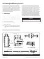
In this design, the bonnet and the spindle are different—there
are two added parts and two additional o-rings. The bonnet is a
two-piece design rather than a one-piece. The top of the bonnet
(7) is the male piece and it screws into the female bottom bonnet
(8). The bottom bonnet has a machined shelf in the top on which
a metal backup plate (39) seats via an o-ring (40), part number
310XX030. (The “XX” in the part number designates the material
and durometer of the o-ring.) The spindle (9) is modified to have a
larger diameter in the lower section to accommodate a 310XX011
O-Ring (40), which slides through the inside diameter of the backup
B. Design Options
B.1 Consolidated* 19000 Series MS & DA
Safety Relief Valves
O-Ring Seat Seal Valves
All Consolidated* 19000 Series Valves are available with
an o-ring seat seal as a design option. This optional design
is bubble tight at 97 percent of set pressures over 100
psig (6.89 barg), in order to meet application requirements
beyond the normal capabilities of metal to metal seat valves.
Consolidated* Series 19000 valves with the O-Ring seat seal
option are identified by the suffix DA. (See Table 14.)
Lifting Levers, Caps and Gags
All Consolidated* 19000 Series Valves are designed so that
10 | GE Oil & Gas
All Consolidated* 19000 Series can be provided by GE
Consolidated* with flanged, or socket weld inlet and outlet
connections, upon customer request.
B.2 19096M-DA-BP Safety Relief Valves
(See Figure 6)
plate (39), providing an area nearly equal to the area of the base
which balances the effects of the back pressure.
C. Nomenclature
Applicable valve nomenclature for Types Consolidated* 19000
Series Male and Female inlet configurations are illustrated in
Figures 1 through 6. Relevant parts nomenclature for optional
lifting levers, caps and the gag, as applicable, are provided in
Figures 1 through 6.
© 2015 General Electric Company. All rights reserved.
IX. Introduction
A. 19000 MS & DA
Safety Relief Valves
B. 19096M-DA-BP
Safety Relief Valves
Consolidated* Series 19000 Portable Pressure Relief Valves
are designed to meet ASME Section VIII requirements for fixed
blowdown pressure relief valves and liquid relief valves. They
may be used for various media such as air, liquids, process
steam and hydrocarbons and may serve as either a safety valve
or a relief valve, depending upon the application.
The 19000 back pressure version is only available in the .096" (2.44
mm) orifice with an O-Ring seat. It is available for steam, liquid or
gas applications and may be furnished with a plain or screwed cap.
The 19096M-DA-BP variation is furnished as a 19096M designation
with a pressure range of 50-2000 psig (3.45-137.90 barg). The
standard medium pressure valve is limited to a minimum of 290
psig (19.99 barg) in the standard 19000 design. The designation
will be used since most of the parts are from the 19096M bill of
material.
Table 1: Performance Criteria for the 19096M-DA-BP Valve
Typical blowdown as a percent of set pressure (At the
low end of the spring range with the maximum allowed
back pressure applied, the blowdown is shortest.)
Liquid: 6 percent – 20 percent
Gas: 3 percent – 16 percent
Liquid: 70 percent of set pressure
Allowable total back pressure (This is the sum of the
variable and constant back pressure, superimposed and
built-up.)
Note: Thermal relief applications may be supplied with back pressures
up to 90 percent of set pressure.
Gas: 50 percent of set pressure
Note: Total back pressure for liquid or gas shall not exceed
400 psig (27.58 barg).
Temperature limits
(Determined by o-ring material selection)
Minimum: -20°F (-28°C)
Maximum: 600°F (315°C)
Set pressure of 50 psig (3.45 barg): 92 percent
Seat tightness
51 psig (3.52 barg) – 100 psig (6.8 barg): 94 percent
101 psig (6.9 barg) – Maximum Rating: 95 percent
Note: Refer to this Table for the performance criteria of this valve. Applications outside of these ranges may cause malfunction of the
intended valve operation.
© 2015 General Electric Company. All rights reserved.
Consolidated 19000 Series Safety Valve Maintenance Manual | 11
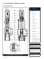
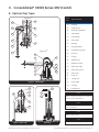
X. Consolidated* 19000 Series SRV
A. Metal Seat Valve
Figure 1a:
-2 Male NPT1
Figure 1b:
-2 Female NPT2
18
9
12
13
17
10
11
6
Part
No.
1
Base
2
Disc
4
Disc Holder
5
Guide
6
Bonnet
9
Spindle
10
Spring Washer
11
Spring
12
Adjusting Screw
13
Adj. Screw Locknut
17
Cap Gasket
18
Screwed Cap
32
Inlet Extension (Not
Shown)
33
Inlet Flange (Not
Shown)
34
Outlet Extension (Not
Shown)
35
Outlet Flange (Not
Shown)
41
Inlet Nipple Extension
(Not Shown) (Optional)
42
Outlet Nipple Ext. (Not
Shown) (Optional)
10
4
2
5
1
9
4
Nomenclature
Note 1
Available as: 19096L, 19110L,19126L, 19226L,
19096M, 19110M, 19126M, 19226M
Note 2
2
5
Figure 1c: -1 Design3
Figure 1: 19000 Metal Seat Valve Construction
12 | GE Oil & Gas
Available as: 19096L, 19110L,19126L, 19226L,
19357L, 19567L, 19096M, 19110M, 19126M,
19226M, 19357M, 19567M, 19096H, 19110H,
19126H, 19226H
Note 3
19110 Valve Not Available.
© 2015 General Electric Company. All rights reserved.
X. Consolidated* 19000 Series SRV (Contd.)
B. Optional Cap Types
Figure 2a1&4
Part
No.
19
25
24
27
20
26
22
17
21
Figure 2b2&4
23
19
32
23
35
27
33
26
34
17
Figure 2: Packed Cap
28
14
27
29
15
26
Nomenclature
14
Gag Bolt
15
Sealing Plug
16
Sealing Plug Gasket
17
Cap Gasket
19
Packed Cap
20
Cam Shaft
21
Bushing
22
Bushing Gasket
23
Packed Lifting Lever
24
Drive Pin
25
O-Ring
26
Release Nut
27
Release Locknut
28
Plain Lever Cap
29
Plain Lifting Lever
30
Cap Screw
31
Lever Pin
32
Lifting Fork
33
Lever Shaft
34
Packing
35
Packing Nut
Note 1
16
Available for: 19096L, M & H; 19110L, M & H; 19126L & M;
19226L & M. Excludes 19096M-DA-BP
31
Note 2
Available for: 19126H; 19226H; 19357L & M; 19357L & M;
Excludes 19096M-DA-BP
30
Note 3
Available for all 19000 valves
Note 4
Figure 3: Plain Cap3 & 4
Figure 4: Typical Screwed Cap
with Gag3
© 2015 General Electric Company. All rights reserved.
Can be provided with a gag if required
Consolidated 19000 Series Safety Valve Maintenance Manual | 13
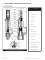
X. Consolidated* 19000 Series SRV (Contd.)
C. Soft Seat Valve
Figure 5a: -1 Male NPT
Figure 5b: -1 Female NPT
18
Part
No.
9
1
Base
3
O-Ring Retainer
4
Disc Holder
10
5
Guide
11
6
Bonnet
9
Spindle
10
Spring Washer
11
Spring
12
Adjusting Screw
13
Adj. Screw Locknut
17
Cap Gasket
18
Screwed Cap
36
O-Ring Retainer Lockscrew
37
O-Ring Seat Seal
41
Inlet Nipple Extension
(Not Shown) (Optional)
42
Outlet Nipple Extension
(Not Shown) (Optional)
12
13
Nomenclature
17
6
10
4
5
1
36
3
37
Figure 5c: Soft Seat Assembly
Figure 5: 19000 O-Ring Soft Seat Valve Construction
14 | GE Oil & Gas
© 2015 General Electric Company. All rights reserved.
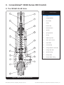
X. Consolidated* 19000 Series SRV (Contd.)
D. The 19096M-DA-BP Valve
9
18
12
13
17
10
11
7
10
39
40
38
8
4
36
Part
No.
Nomenclature
1
Base
3
O-Ring Retainer
4
Disc Holder
5
Guide
7
Bonnet Top
8
Bonnet Bottom
9
Spindle
10
Spring Washer
11
Spring
12
Adjusting Screw
13
Adj. Screw Locknut
17
Cap Gasket
18
Screwed Cap
36
O-Ring Retainer Lockscrew
37
O-Ring Seat Seal
38
Spindle O-Ring
39
Backup Plate
40
Backup Plate O-Ring
3
37
5
1
Figure 6: 19000-DA-BP Valve Construction
© 2015 General Electric Company. All rights reserved.
Consolidated 19000 Series Safety Valve Maintenance Manual | 15
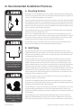
XI. Recommended Installation Practices
A. Mounting Position
Mount SRVs in a vertical (upright) position (in accordance with API RP 530). Installing a safety
relief valve in any position other than vertical (±1 degree) will adversely affect its operation as
a result of the induced misalignment of moving parts.
A stop valve may be placed between the pressure vessel and its relief valve only as permitted by
code regulations. If a stop valve is located between the pressure vessel and SRV, the stop valve
port area should equal or exceed the nominal internal area associated with the pipe size of the
SRV inlet. The pressure drop from the vessel to the SRV shall not exceed three (3) percent of the
valve’s set pressure, when flowing at full capacity.
Mount safety relief valves in a
vertical, upright position only.
The threaded inlet and outlet ports and sealing faces of the valve and all connecting piping
must be free from dirt, sediment and scale.
In the case of screwed/portable valves, use caution to avoid unscrewing bonnet from the
base; if a pipe wrench is used to install or remove the base, ensure that the wrench is placed
on the flats of the base and not on the bonnet. If the bonnet/ base joint is broken, the valve
should be retested to ensure proper set pressure and function of the valve.
Position SRVs for easy access and/or removal so that servicing can be properly performed.
Ensure sufficient working space is provided around and above the valve.
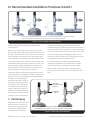
B. Inlet Piping
The inlet piping (see Figure 7) to the valve should be short and directly from the vessel or
equipment being protected. The radius of the connection to the vessel should permit smooth
flow to the valve. Avoid sharp corners. If this is not practical, then the inlet should be at least
one additional pipe diameter larger.
Do not mount valve at the end
of pipe through which there
is normally no flow or near
elbows, tees, bends, etc.
The pressure drop from the vessel to the valve shall not exceed three (3) percent of valve
set pressure when the valve is allowing full capacity flow. The inlet piping should never be
smaller in diameter than the inlet connection of the valve. Excessive pressure drop in gas,
vapor, or flashing-liquid service at the inlet of the SRV will cause the extremely rapid opening
and closing of the valve, which is known as “chattering.” Chattering will result in lowered
capacity and damage to the seating surfaces. The most desirable installation is that in which
the nominal size of the inlet piping is the same as, or greater than, the nominal size of the
valve inlet flange and in which the length does not exceed the face-to-face dimensions of a
standard tee of the required pressure class.
Do not locate SRV inlets where excessive turbulence is present, such as near elbows, tees,
bends, orifice plates or throttling valves.
Section VIII of the ASME Boiler and Pressure Vessel Code requires the inlet connection design
to consider stress conditions during valve operation, caused by external loading, vibration, and
loads due to thermal expansion of the discharge piping.
The determination of reaction forces during valve discharge is the responsibility of the vessel
and/or piping designer. GE publishes certain technical information about reaction forces
under various fluid flow conditions, but assumes no liability for the calculations and design of
the inlet piping.
Heed all service manual
warnings. Read installation
instructions before installing
valve(s).
16 | GE Oil & Gas
External loading, by poorly designed discharge piping and support systems, and forced
alignment of discharge piping can cause excessive stresses and distortions in the valve as
well as the inlet piping. The stresses in the valve may cause a malfunction or leak. Therefore,
© 2015 General Electric Company. All rights reserved.
XI. Recommended Installation Practices (Contd.)
The pressure drop (P.D.) between the source of pressure in the protected equipment and the
pressure relief valve inlet is not to exceed 3 percent of the valve set pressure.
Figure 7: Pressure Drop on the Inlet Piping
discharge piping must be independently supported and
carefully aligned.
Vibrations in the inlet piping systems may cause valve seat
leakage and/or fatigue failure. These vibrations may cause the
disc seat to slide back and forth across the base seat and may
result in damage to the seating surfaces. Also, vibration may
cause separation of the seating surfaces and premature wear
to valve parts. High-frequency vibrations are more detrimental
to SRV tightness than low-frequency vibrations. This effect can
be minimized by providing a larger difference between the
operating pressure of the system and the set pressure of the
valve, particularly under high frequency conditions.
Temperature changes in the discharge piping may be caused
by fluid flow in from the discharge of the valve or by prolonged
exposure to the sun or heat radiated from nearby equipment.
A change in the discharge piping
temperature will cause a change in
the length of the piping, which may
cause stresses to be transmitted to
the SRV and its inlet piping. Proper
support, anchoring or provision for
flexibility of the discharge piping can
prevent stresses caused by thermal
changes. Do not use fixed supports.
unsupported discharge piping consisting of more than a
companion flange long-radius elbow, and a short vertical pipe is
not recommended. Use spring supports to connect outlet piping
to prevent thermal expansion from creating strains on the valve.
The discharge piping should be designed to allow for vessel
expansion as well as expansion of the discharge pipe itself. This
is particularly important on long distance lines.
A continual oscillation of the discharge piping (wind loads)
may induce stress distortion in the valve body. The resultant
movement of the valve’s internal parts may cause leakage.
Where possible, use properly supported drainage piping to
prevent the collection of water or corrosive liquid in the valve
body.
Cap may be
required for weather
protection
G
ON
WR
Long-Radius
Elbow
C. Outlet Piping
Alignment of the internal parts of the
SRV is important to ensure proper
operation (see Figure 8). Although
the valve body will withstand a
considerable mechanical load,
Vessel
Vessel
For a closed system, always keep piping strains isolated from the
Pressure Relief Valve, regardless of process operation and temperature.
© 2015 General Electric Company. All rights reserved.
Figure 8: Outlet Piping Considerations
Consolidated 19000 Series Safety Valve Maintenance Manual | 17
XI. Recommended Installation Practices (Contd.)
When two or more valves are piped to discharge into a common header, the built-up
backpressure resulting from the opening of one (or more) valve(s) may cause a superimposed
backpressure in the remaining valves. Under these conditions, the use of the 19096-DA-BP
model is recommended.
In every case, the nominal discharge pipe size should be at least as large as the nominal size
of the SRV outlet flange. In the case of long discharge piping, the nominal discharge pipe size
must sometimes be much larger.
As a final point, the discharge piping size is never less than the size of the valve outlet, nor
heavier than schedule 40 pipe size. In addition, the discharge piping must be designed to limit
the total backpressure to a maximum of 10 percent of the valve set pressure, or 400 psig
(27.58 barg), whichever is smaller.
Wear necessary protective
equipment to prevent
possible injury
ATTENTION!!
Undersized discharge piping could create
built-up backpressure.
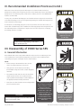
XII. Disassembly of 19000 Series SRV
A. General Information
Consolidated* SRVs can be easily disassembled for inspection, the reconditioning of seats
or the replacement of internal parts. Appropriate set pressure can be established after
reassembly. (See Figures 1 through 6 for parts nomenclature.)
NOTES:
• Before starting to disassemble the valve, be sure
there is no material pressure in the vessel.
•
Many pressure vessels that are protected by
Consolidated* safety relief valves contain dangerous
materials.
•
Decontaminate and clean the valve inlet and outlet
and all external surfaces in accordance with the
cleaning and decontaminating recommendations in
the appropriate Material Safety Data Sheet.
•
Parts from one valve should not be interchanged with
parts from another valve.
ATTENTION!!
Do not interchange parts from one valve with
parts from another valve.
18 | GE Oil & Gas
Before disassembling the
valve, ensure there is no media
pressure in the vessel.
Many pressure vessels
protected by Consolidated*
safety relief valves contain
dangerous materials.
Decontaminate and clean
the valve inlet, outlet, and
all external surfaces in
accordance with the cleaning
and decontaminating
recommendations in the
appropriate Material Safety
Data Sheet.
Valve caps and bonnets can
trap fluids. Use caution when
removing to prevent injury or
environmental damage.
© 2015 General Electric Company. All rights reserved.
XII. Disassembly of 19000 Series SRV (Contd.)
B. Disassembly
1.
Metal Seat Valves (See Figure 1)
a.Remove the cap (18) (including lifting gear, if any); then,
remove the cap (17) gasket.
b.Measure the position of the valve adjusting screw (12)
and record before removal. Measure from the top of the
screw to the adjusting screw locknut (13).
c.Loosen the adjusting screw locknut (13) and remove
the adjusting screw (12) from the bonnet (6).
d.
Unscrew the bonnet (6) from the base (1).
e.Remove the spindle (9), spring (11), and spring washers
(10).
f.Remove the guide (5), disc holder (4), and disc (2) from
the base (1).
2.
O-Ring Seat Seal Valves (DA)
(See Figure 5)
Follow steps (a) through (e) for Metal Seat Valves above.
f.Remove the guide (5) and O-Ring disc holder assembly
from the base.
e.Remove the spindle (9), backup plate (39), spring (11)
and spring washers (10).
f.
Unscrew the bonnet bottom (7) from the base (1).
g.
Remove the guide (5) and O-Ring retainer (3).
h.Remove the retainer lockscrew (36) and the O-Ring
retainer (3).
i.Carefully remove the seat O-Ring (37). Be sure not to
damage the O-Ring groove in the disc holder (4)
C. Cleaning
19000 Series Safety Relief Valve internal parts may be cleaned
with industrial solvents, cleaning solutions and wire brushes.
If you are using cleaning solvents, take precautions to protect
yourself from potential danger from breathing fumes, chemical
burns or explosion. See the solvent’s Material Safety Data Sheet
for safe handling recommendations and personal protective
equipment. It is not recommended to “sandblast” internal
parts as it can reduce the dimensions of the parts. The base (1),
bonnet (6) and cap (18) castings may be sandblasted with care
not to erode internal surfaces or damage machined surfaces.
If grit blasting is required, the use of glass bead material is
recommended.
g.Remove the o-ring retainer lockscrew (36) and the
O-Ring retainer (3).
h.Carefully remove the O-Ring Seat Seal (37). Be sure not to
damage the O-Ring groove in the disc holder (4).
3.
19096M-DA-BP Valves (See Figure 6)
a.Remove the cap (18) (including lifting gear, if any); then
remove the cap gasket (17).
b.Measure the position of the valve adjusting screw (12)
and record before removal. Measure from the top of
the screw to the adjusting screw locknut (13).
c.Loosen the adjusting screw locknut (13) and remove the
adjusting screw (12) from the bonnet top (7). (d) Unscrew
the bonnet top (7) from the bonnet bottom (8).
© 2015 General Electric Company. All rights reserved.
Follow recommendations for
safe handling in the solvent’s
Material Safety Data Sheet and
observe safe practices for any
cleaning method.
Consolidated 19000 Series Safety Valve Maintenance Manual | 19
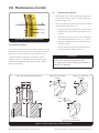
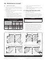
XIII. Maintenance
A. Metal Seat Valves (MS)
same lap using the lapping motion described above. Low
sections on the seating surface will show up as a shadow
in contrast to the shiny portion. If shadows are present,
further lapping is necessary and only laps known to be flat
should now be used. Only a few minutes will be required to
remove the shadows.
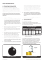
A1. Precautions and Hints for Lapping Seats
Reconditioning of the seat surface may be accomplished by
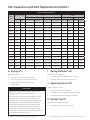
lapping with a flat cast iron ring lap coated with a 1000 grit
lapping compound or its equivalent (see Table 17). A cast iron
lap, coated with a lapping compound, is used for reconditioning
the seating surfaces of the base (1) and disc (2). The following
will enable maintenance personnel to do a “professional” job of
lapping seats:
1.
Keep work materials clean.
2.
Always use a fresh lap. If signs of wearing (out of flatness)
are evident, recondition the lap. Reconditioning of laps
is accomplished by lapping them on a flat lapping plate.
The lapping should be done with a figure-eight motion
as indicated in Figure 9. To assure the best results when
lapping seats, the laps should be reconditioned after each
usage.
3.
4.
9.
When the lapping is completed, any lines appearing as
cross scratches can be removed by rotating the lap (which
has been wiped clean of compounds) on the seat about its
own axis.
10. The seat should now be thoroughly cleaned using a lintfree cloth and a cleansing fluid.
2.
Lapping the Base Seat
For -1 Material Seat Design
The base seat may be reconditioned using the lapping
procedure; however, the dimensions provided in Table 2, should
be used to determine the seat width.
Apply a very thin layer of compound to the lap. This will
prevent rounding off the edges of the seat.
Keep the lap squarely on the flat surface and avoid any
tendency to rock the lap which causes rounding of the
seat.
5.
When lapping, keep a firm grip on the part to prevent the
possibility of dropping it and damaging the seat.
6.
Lap, using an eccentric, or figure-eight motion, in all
directions, while at the same time, applying uniform
pressure and rotating the lap slowly (see Figure 9).
7.
Replace the compound frequently after wiping off the old
compound, and apply more pressure to speed the cutting
action of the compound.
8.
To check the seating surfaces, remove all compounds from
both the seat and the lap. Then, shine the seat with the
LAPPING PLATE
Table 2: Base Lapping Width
(-1 Metal Seat Design Only)
SET PRESSURE
psig
min.
5
101
301
801
SEAT WIDTH
barg
max.
100
300
800
UP
min.
0.345
6.897
20.685
55.159
max.
6.896
20.684
55.158
UP
in.
mm
.010
0.25
.015
0.38
.020
0.51
Note 1
Note 1: Add .005” (0.127 mm) per 100 psig (6.896 barg), not to
exceed .070” (1.78 mm).
The seat width can be measured by the use of a “Measuring
Magnifier” (see Figure 10a). GE recommends the use of Model
S1-34-35-37 (Bausch and Lomb Optical Co.) or an equivalent.
This is a seven power glass with a .750" (19.05 mm) scale
showing graduations of .005" (0.13 mm). The use of this scale in
measuring the seat width is shown in Figure 10b.
RING LAP
Measuring
Magnifier
Base
Figure 9: Lapping Pattern
20 | GE Oil & Gas
Figure 10a: Measuring Magnifier
© 2015 General Electric Company. All rights reserved.
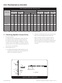
XIII. Maintenance (Contd.)
A3.
Nozzle
Width
0
0.1
03
0.3
0.2
0..4
0.
4
0.5
0.5
0
0.6
1.
When the base seat cannot be repaired by lapping, it can
be machined as shown in Figure 11, using the dimensions
provided in Tables 3 to 5.
2.
GE recommends that the following procedure be adhered
to when machining the base seat:
0.7
Flat Seat
a. Using a four-jaw chuck, align the base so that surfaces
marked X and U run true within .001” (0.03 mm) on an
indicator.
5° Taper
b. Take light cuts on the seat surface until all damage is
removed. Reestablish dimensions “B”, “C”, “F”, “G”, “H”
and Angle I. When L (minimum) is obtained, the base
should be replaced.
Figure 10b: Measuring Magnifier Detail
For -2 Metal Seat Design
c. After all machining has been accomplished, lap the
seat using same procedure for base seat.
The -2 metal seat design is a flat seat design. The base seat may
be lapped or machined if necessary to verify that the seat ("N" of
Figure 11) is free from indentions, scratches, high spots, etc.
ATTENTION!!
If additional lighting is required for verifying the seat, GE
suggests a goose-neck flashlight similar to the Type A Lamp
Assembly Flashlight (Standard Molding Corporation, Dayton,
Ohio) or an equivalent.
Figure 11a: Base General Dimensions
Machining the Base Seat
19000H and 19000 DA bases have flat seats
(90° angle) across the entire seating surface from B
diameter to D diameter.
Figure 11b: Metal Seat
-1 Design
Figure 11c: Metal Seat
-2 Design
N
C
E
D
B
G
F
I
F
J
Y
K
X
H
View Y
View Y
A
.003”
.012” +- .002”
U
0.08 mm )
(0.30 +
- 0.05
N
L
F
View Y
Figure 11d: Soft Seat Base
Figure 11: Machining the Metal and Soft Seat Base
© 2015 General Electric Company. All rights reserved.
Consolidated 19000 Series Safety Valve Maintenance Manual | 21
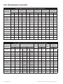
XIII. Maintenance (Contd.)
Table 3: 19000-1 Series Metal Seat (MS) Base Re-work Dimensions
B ± .002"
(± 0.05 mm)
A min.
Valve Type
D ± .002"
(± 0.05 mm)
C min.
E ± .003"
(± 0.08 mm)
F ± .005"
(± 0.13 mm)
in.
mm
in.
mm
in.
mm
in.
mm
in.
mm
in.
mm
19096L
0.350
8.89
0.395
10.03
0.006
0.15
0.457
11.61
0.503
12.78
0.030
0.76
19126L
0.401
10.19
0.453
11.51
0.006
0.15
0.523
13.28
0.579
14.71
0.030
0.76
19226L
0.537
13.64
0.606
15.39
0.006
0.15
0.701
17.81
0.781
19.84
0.030
0.76
19357L
0.675
17.15
0.762
19.35
0.006
0.15
0.881
22.38
0.987
25.07
0.038
0.97
19567L
0.850
21.59
0.960
24.38
0.006
0.15
1.109
28.17
1.247
31.67
0.048
1.22
19096M
0.350
8.89
0.395
10.03
0.011
0.28
0.457
11.61
0.503
12.78
0.030
0.76
19126M
0.401
10.19
0.453
11.51
0.011
0.28
0.523
13.28
0.579
14.71
0.030
0.76
19226M
0.537
13.64
0.606
15.39
0.011
0.28
0.701
17.81
0.781
19.84
0.030
0.76
19357M
0.675
17.15
0.762
19.35
0.011
0.28
0.881
22.38
0.987
25.07
0.038
0.97
19567M
0.850
21.59
0.960
24.38
0.010
0.25
1.109
28.17
1.247
31.67
0.048
1.22
19096H
0.350
8.89
0.395
10.03
Flat
Flat
0.457
11.61
0.503
12.78
0.030
0.76
19126H
0.401
10.19
0.453
11.51
Flat
Flat
0.523
13.28
0.579
14.71
0.030
0.76
19226H
0.537
13.64
0.606
15.39
Flat
Flat
0.701
17.81
0.781
19.84
0.030
0.76
Table 3: 19000-1 Series Metal Seat (MS) Base Re-work Dimensions (Contd.)
Valve Type
G ± .005
(± 0.13 mm)
H
in.
mm
19096L
0.188
4.78
0.784
19126L
0.216
5.49
0.784
19226L
0.289
7.34
1.034
19357L
0.363
9.22
1.502
19567L
0.457
11.61
1.502
19096M
0.188
4.78
0.784
19126M
0.216
5.49
0.784
19226M
0.289
7.34
1.034
19357M
0.363
9.22
1.502
19567M
0.457
11.61
1.502
19096H
0.188
4.78
1.034
19126H
0.156
3.96
1.524
19226H
0.210
5.33
1.504
22 | GE Oil & Gas
I
in.
+ 0.002
- 0.003
+ 0.002
- 0.003
+ 0.002
- 0.003
+ 0.003
- 0.002
+ 0.003
- 0.002
+ 0.002
- 0.003
+ 0.002
- 0.003
+ 0.002
- 0.003
+ 0.003
- .0002
+ 0.003
- .0002
+ 0.002
- 0.003
+ 0.002
- 0.003
+ 0.002
- 0.003
mm
19.91
19.91
26.26
38.15
38.15
19.91
19.91
26.26
38.15
38.15
26.26
38.71
38.20
+ 0.005
- 0.008
+ 0.005
- 0.008
+ 0.005
- 0.008
+ 0.008
- 0.005
+ 0.008
- 0.005
+ 0.005
- 0.008
+ 0.005
- 0.008
+ 0.005
- 0.008
+ 0.008
- 0.005
+ 0.008
- 0.005
+ 0.005
- 0.008
+ 0.005
- 0.008
+ 0.005
- 0.008
(angle)
J ± .005
(± 0.13 mm)
in.
mm
15°
0.020
0.51
15°
0.023
15°
L min.
K
(angle)
in.
mm
30°
0.261
6.63
0.58
30°
0.261
6.63
0.030
0.76
30°
0.261
6.63
5°
0.038
0.97
30°
0.323
8.20
5°
0.048
1.22
30°
0.323
8.20
15°
0.030
0.76
30°
0.261
6.63
15°
0.030
0.76
30°
0.261
6.63
15°
0.030
0.76
30°
0.261
6.63
5°
0.038
0.97
30°
0.323
8.20
5°
0.048
1.22
30°
0.323
8.20
Flat
0.030
0.76
30°
0.261
6.63
Flat
0.030
0.76
30°
0.323
8.20
Flat
0.030
0.76
30°
0.323
8.20
© 2015 General Electric Company. All rights reserved.
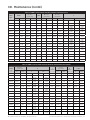
XIII. Maintenance (Contd.)
Table 4: 19000-2 Series Metal Seat (MS) Base Re-work Dimensions
Valve
Type
B ± .002"
(± 0.05 mm)
A min.
C min.
D ± .002"
(± 0.05 mm)
E ± .003"
(± 0.08 mm)
F
in.
mm
in.
mm
in.
in.
mm
in.
mm
19096L
0.350
8.89
0.408
10.36
N/A
0.457
11.61
0.503
12.78
0.025
in.
± 0.001
0.64
mm
± 0.03
19110L
0.375
9.53
0.408
10.36
N/A
0.457
11.61
0.503
12.78
0.025
± 0.001
0.64
± 0.03
0.61
0.61
+ 0.05
- 0.00
+ 0.05
- 0.00
19126L
0.401
10.19
0.463
11.76
N/A
0.523
13.28
0.579
14.71
0.024
19226L
0.537
13.64
0.625
15.88
N/A
0.701
17.81
0.781
19.84
0.024
+ 0.002
- 0.000
+ 0.002
- 0.000
19357L
0.675
17.15
0.796
20.22
N/A
0.881
22.38
0.987
25.07
0.022
± 0.002
0.56
± 0.05
19567L
0.850
21.59
1.000
25.40
N/A
1.109
28.17
1.247
31.67
0.022
± 0.002
0.56
± 0.05
0.61
0.61
+ 0.05
- 0.00
+ 0.05
- 0.00
+ 0.05
- 0.00
19096M
0.350
8.89
0.408
10.36
N/A
0.457
11.61
0.503
12.78
0.024
19110M
0.375
9.53
0.408
10.36
N/A
0.457
11.61
0.503
12.78
0.024
19126M
0.401
10.19
0.463
11.76
N/A
0.523
13.28
0.579
14.71
0.024
+ 0.002
- 0.000
+ 0.002
- 0.000
+ 0.002
- 0.000
19226M
0.537
13.64
0.625
15.88
N/A
0.701
17.81
0.781
19.84
0.025
± 0.001
0.64
± 0.03
0.61
0.61
+ 0.05
- 0.00
+ 0.05
- 0.00
0.61
19357M
0.675
17.15
0.796
20.22
N/A
0.881
22.38
0.987
25.07
0.024
19567M
0.850
21.59
1.000
25.40
N/A
1.109
28.17
1.247
31.67
0.024
+ 0.002
- 0.000
+ 0.002
- 0.000
19096H
0.350
8.89
0.395
10.03
N/A
0.457
11.61
0.503
12.78
0.022
± 0.002
0.56
± 0.05
19110H
0.375
9.53
0.395
10.03
N/A
0.457
11.61
0.503
12.78
0.022
± 0.002
0.56
± 0.05
19126H
0.401
10.19
0.444
11.28
N/A
0.523
13.28
0.579
14.71
0.024
± 0.002
0.61
± 0.05
19226H
0.537
13.64
0.616
15.65
N/A
0.701
17.81
0.781
19.84
0.022
± 0.002
0.56
± 0.05
Table 4: 19000-2 Series Metal Seat (MS) Base Re-work Dimensions (Contd.)
Valve
Type
G ± .005"
(± 0.13 mm)
H
I
in.
(angle)
in.
mm
mm
19096L
0.190
4.83
0.787
± 0.001
19.99
± 0.03
19110L
0.190
4.83
0.787
± 0.001
19.99
19.96
J ± .005"
(± 0.13 mm)
in.
mm
Flat
0.022
0.56
± 0.03
Flat
0.022
Flat
20.07
+ 0.05
- 0.00
+ 0.05
- 0.00
+ 0.08
- 0.05
+ 0.08
- 0.05
+ 0.05
- 0.00
+ 0.05
- 0.00
+ 0.05
- 0.00
L min.
K
(angle)
in.
mm
30°
0.261
6.63
0.56
30°
0.261
6.63
0.025
0.64
30°
0.261
6.63
Flat
0.032
0.81
30°
0.261
6.63
Flat
0.038
0.97
30°
0.323
8.20
Flat
0.048
1.22
30°
0.323
8.20
Flat
0.022
0.56
30°
0.261
6.63
Flat
0.022
0.56
30°
0.261
6.63
Flat
0.025
0.64
30°
0.261
6.63
19126L
0.218
5.54
0.786
19226L
0.291
7.39
1.036
19357L
0.363
9.22
1.502
19567L
0.457
11.61
1.502
19096M
0.122
3.10
0.790
19110M
0.122
3.10
0.790
19126M
0.127
3.23
0.790
+ 0.002
- 0.000
+ 0.002
- 0.000
+ 0.003
- 0.002
+ 0.003
- 0.002
+ 0.002
- 0.000
+ 0.002
- 0.000
+ 0.002
- 0.000
19226M
0.212
5.38
1.037
± 0.001
26.34
± 0.03
Flat
0.032
0.81
30°
0.261
6.63
19357M
0.246
6.25
1.550
39.37
0.040
1.02
30°
0.323
8.20
0.302
7.67
1.574
Flat
0.050
1.27
30°
0.323
8.20
19096H
0.120
3.05
1.038
Flat
0.030
0.76
30°
0.261
6.63
19110H
0.120
3.05
1.038
Flat
0.030
0.76
30°
0.261
6.63
19126H
0.127
3.23
1.502
Flat
0.032
0.81
30°
0.323
8.20
19226H
0.210
5.33
1.504
+ 0.05
- 0.00
+ 0.05
- 0.00
+ 0.08
- 0.05
+ 0.08
- 0.05
+ 0.05
- 0.08
+ 0.05
- 0.08
Flat
19567M
+ 0.002
- 0.000
+ 0.002
- 0.000
+ 0.003
- 0.002
+ 0.003
- 0.002
+ 0.002
- 0.003
+ 0.002
- 0.003
Flat
0.030
0.76
30°
0.323
8.20
© 2015 General Electric Company. All rights reserved.
26.31
38.15
38.15
20.07
20.07
39.98
26.37
26.37
38.20
38.20
Consolidated 19000 Series Safety Valve Maintenance Manual | 23
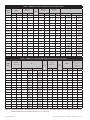
Table 5: 19000 Series Soft Seat (DA) Base Re-work Dimensions
XIII. Maintenance
(Contd.)
Valve
Type
A min.
in.
mm
B ±.002"
(±0.05 mm)
in.
D ±.002"
(±0.05 mm)
C min.
mm
in.
E ±.003"
(±0.08 mm)
mm
in.
F
mm
in.
19096L
0.350
8.89
0.395
10.03
Flat
0.457
11.61
0.503
12.78
0.050
19110L
0.375
9.53
0.395
10.03
Flat
0.457
11.61
0.503
12.78
0.050
19126L
0.401
10.19
0.453
11.51
Flat
0.523
13.28
0.579
14.71
0.050
19226L
0.537
13.64
0.606
15.39
Flat
0.701
17.81
0.781
19.84
0.054
19357L
0.675
17.15
0.762
19.35
Flat
0.893
22.68
0.987
25.07
0.062
19567L
0.850
21.59
0.960
24.38
Flat
1.109
28.17
1.247
31.67
0.062
19096M
0.350
8.89
0.395
10.03
Flat
0.457
11.61
0.503
12.78
0.050
19110M
0.375
9.53
0.395
10.03
Flat
0.457
11.61
0.503
12.78
0.050
19126M
0.401
10.19
0.453
11.51
Flat
0.523
13.28
0.579
14.71
0.084
19226M
0.537
13.64
0.606
15.39
Flat
0.701
17.81
0.781
19.84
0.084
19357M
0.675
17.15
0.762
19.35
Flat
0.893
22.68
0.987
25.07
0.092
19567M
0.850
21.59
0.960
24.38
Flat
1.109
28.17
1.247
31.67
0.128
19096H
0.350
8.89
0.395
10.03
Flat
0.457
11.61
0.503
12.78
0.048
19110H
0.375
9.53
0.395
10.03
Flat
0.457
11.61
0.503
12.78
0.048
19126H
0.401
10.19
0.453
11.51
Flat
0.523
13.28
0.579
14.71
0.048
19226H
0.537
13.64
0.606
15.39
Flat
0.701
17.81
0.781
19.84
0.052
mm
+ 0.002
- 0.000
+ 0.002
- 0.000
+ 0.002
- 0.000
+ 0.002
- 0.000
+ 0.003
- 0.002
+ 0.003
- 0.002
+ 0.002
- 0.000
+ 0.002
- 0.000
+ 0.002
- 0.000
+ 0.002
- 0.000
+ 0.003
- 0.002
+ 0.002
- 0.003
+ 0.002
- 0.003
+ 0.002
- 0.003
+ 0.002
- 0.003
+ 0.003
- 0.002
1.270
1.270
1.270
1.372
1.575
1.575
1.270
1.270
2.134
2.134
2.337
3.251
1.219
1.219
1.219
1.321
+ 0.050
- 0.000
+ 0.050
- 0.000
+ 0.050
- 0.000
+ 0.050
- 0.000
+ 0.076
- 0.050
+ 0.076
- 0.050
+ 0.050
- 0.000
+ 0.050
- 0.000
+ 0.050
- 0.000
+ 0.050
- 0.000
+ 0.076
- 0.050
+ 0.050
- 0.076
+ 0.050
- 0.076
+ 0.050
- 0.076
+ 0.050
- 0.076
+ 0.076
- 0.050
Table 5: 19000 Series Soft Seat (DA) Base Re-work Dimensions (Contd.)
Valve
Type
G ±.005”
(±0.13 mm)
in.
H
(angle)
mm
in.
19096L
0.190
4.83
0.786
19110L
0.190
4.83
0.786
19126L
0.218
5.54
0.786
19226L
0.291
7.39
1.036
19357L
0.363
9.22
1.503
19567L
0.457
11.61
1.503
19096M
0.190
4.83
0.812
19110M
0.190
4.83
0.812
19126M
0.180
4.57
0.810
19226M
0.212
5.38
1.100
19357M
0.363
9.22
1.594
19567M
0.300
7.62
1.596
19096H
0.188
4.78
1.060
19110H
0.188
4.78
1.060
19126H
0.156
3.96
1.524
19226H
0.210
5.33
1.504
Note 1:
I
mm
+ 0.002
- 0.000
+ 0.002
- 0.000
+ 0.002
- 0.003
+ 0.002
- 0.000
+ 0.002
- 0.003
+ 0.003
- 0.002
+ 0.002
- 0.000
+ 0.002
- 0.000
+ 0.002
- 0.000
+ 0.002
- 0.000
+ 0.002
- 0.003
+ 0.003
- 0.002
+ 0.002
- 0.003
+ 0.002
- 0.003
+ 0.002
- 0.003
+ 0.002
- 0.003
19.96
19.96
19.96
26.31
38.18
38.18
20.62
20.62
20.57
27.94
40.49
40.54
26.92
26.92
38.71
38.20
+ 0.050
- 0.000
+ 0.050
- 0.000
+ 0.050
- 0.076
+ 0.050
- 0.000
+ 0.050
- 0.076
+ 0.076
- 0.050
+ 0.050
- 0.000
+ 0.050
- 0.000
+ 0.050
- 0.000
+ 0.050
- 0.000
+ 0.050
- 0.076
+ 0.076
- 0.050
+ 0.076
- 0.050
+ 0.050
- 0.076
+ 0.050
- 0.076
+ 0.050
- 0.076
J ±.005”
(±0.13 mm)
in.
mm
Flat
0.022
0.56
Flat
0.022
0.56
Flat
0.025
Flat
K
L min.
(angle)
M Liquid Valve
only1 + .002/.003"
(+ 0.05/- 0.08
mm)
in.
mm
in.
mm
30°
0.261
6.63
0.032
0.81
30°
0.261
6.63
0.050
1.27
0.64
30°
0.261
6.63
0.032
0.81
0.032
0.81
30°
0.261
6.63
0.032
0.81
Flat
0.038
0.97
30°
0.323
8.20
0.040
1.02
Flat
0.048
1.22
30°
0.323
8.20
0.050
1.27
Flat
0.032
0.81
30°
0.261
6.63
N/A
N/A
Flat
0.030
0.76
30°
0.261
6.63
N/A
N/A
Flat
0.030
0.76
30°
0.261
6.63
N/A
N/A
Flat
0.032
0.81
30°
0.261
6.63
N/A
N/A
Flat
0.038
0.97
30°
0.323
8.20
N/A
N/A
Flat
0.048
1.22
30°
0.323
8.20
N/A
N/A
Flat
0.030
0.76
30°
0.261
6.63
N/A
N/A
Flat
0.030
0.76
30°
0.261
6.63
N/A
N/A
Flat
0.030
0.76
30°
0.323
8.20
N/A
N/A
Flat
0.030
0.76
30°
0.323
8.20
N/A
N/A
Soft seat (DA) valves for liquid service from 5 - 100 psig (0.34 - 6.89 barg) require a special base for 19000L Series.
Refer to Dimension “M” instead of Dimension “F” in this case.
24 | GE Oil & Gas
© 2015 General Electric Company. All rights reserved.
XIII. Maintenance (Contd.)
A4.
1.
2.
Machining the Disc Seat
When the disc seat cannot be repaired by lapping, it can
be machined as shown in Figure 12, using the dimensions
provided in Table 7.
GE recommends that the following procedure be adhered
to when machining the disc seat:
a. Grip the disc in a collet.
b. True up the disc so that surfaces marked X and Y run
true within .001” (0.03 mm) on an indicator.
c. Take light cuts across the seating surface until the
damage is removed. Dimensions “R” and “Q”, (and 15°
angle when applicable) must be maintained.
psig
bar
5 to 800
-0.34 to -55.16
801 Above
Note 1:
-55.23 Above
Flat
Flat
1.
Replacing the o-ring retainer (3)
If slight damage is present, the o-ring retainer can be
refurbished by either lapping or machining. O-Ring retainer
should be replaced if severely damaged or if dimension S
(minimum) is exceeded (see Figure 12 and Table 7).
The O-Ring always should be replaced to ensure seat
tightness.
Disc Width
190, 961,
911, 019,
126
in. mm
B. O-Ring Seat Seal Valves (DA)
ATTENTION!!
Table 6: Disc Seat Lapping Width
(-2 Metal Seat Design)
Set Pressure
d. The disc is now ready for lapping. (See Table 6 for
proper seat width).
e. When the minimum thickness dimension “S” is reached,
the disc should be replaced.
192, 261,
19019 VALVE
935, 719,
TYPE
567
in. mm in. mm.
Flat
0.02
-0.51
0.010 -0.254
Flat
Note
1
Note
1
0.010
2.Polishing the base seat
Normally the base seating area on this type of valve is
not damaged, since the o-ring absorbs the impact when
foreign material is trapped between the o-ring and the
base seating area. The o-ring will therefore hold a bubble
tight seal with slight indications on the base seating
surface. Nevertheless, slight indications on the base seat
surface may be removed by lapping the base.
0.254
Add .005" (0.125 mm) per 100 psig (6.896 bar), until disc seat
width has reached the maximum available width.
Figure 12a: Metal Seat Disc (-1 Design)
T
Figure 12b: Metal Seat Disc (-2 Design)
Q
Q
T
X
X
S
S
R
R
Y
15˚
LAPPED
SURFACE
45˚
Figure 12c: Soft Seat O-Ring Retainer (19096-19126)
Figure 12d: Soft Seat O-Ring Retainer (19226-19567)
Q
S
Q
S
R
Y
Y
450
Figure 12: Disc and O-Ring Retainer (Metal Seat & Soft Seat)
© 2015 General Electric Company. All rights reserved.
Consolidated 19000 Series Safety Valve Maintenance Manual | 25
XIII. Maintenance (Contd.)
Table 7: Rework Dimensions of the Disc Seat
Disc (Metal Seat)
Q
Valve Type
O-Ring Retainer (Soft Seat)
S min.
(-1 Design)
(-2 Design)
R min.
in.
mm
in.
mm
in.
mm
19096L,M
0.461
11.71
0.030
0.76
0.248
6.30
19096H
0.461
11.71
0.030
0.76
0.248
6.30
R min.
mm
in.
mm
S min.
mm
in.
in.
mm
0.239
6.07
0.426
10.82
N/A
N/A
0.158
4.01
0.496
12.60
0.426
10.82
N/A
N/A
0.158
4.01
19110L,M
0.461
11.71
0.030
0.76
N/A
N/A
0.239
6.07
0.426
10.82
N/A
N/A
0.158
4.01
19110H
0.461
11.71
0.030
0.76
N/A
N/A
0.496
12.60
0.426
10.82
N/A
N/A
0.158
4.01
19126L,M
0.527
13.39
0.030
0.76
0.248
6.30
0.246
6.25
0.489
12.42
N/A
N/A
0.158
4.01
19126H
0.527
13.39
0.030
0.76
0.248
6.30
0.496
12.60
0.489
12.42
N/A
N/A
0.158
4.01
19226L1,M1
0.705
17.91
0.030
0.76
0.310
7.87
0.277
7.04
0.676
17.17
0.032
0.81
0.206
5.23
19226H1
0.705
17.91
0.030
0.76
0.310
7.87
0.551
14.00
0.676
17.17
0.032
0.81
0.206
5.23
1
1
0.885
22.48
0.030
0.76
0.498
12.65
0.459
11.66
0.852
21.64
0.032
0.81
0.251
6.38
1
1
1.113
28.27
0.030
0.76
0.498
12.65
0.478
12.14
1.058
26.87
0.032
0.81
0.251
6.38
19357L ,M
19567L ,M
Note 1:
These valves have a 15° angle as shown in Figure 12 (-2 Metal Seat Design).
C. Checking Spindle Concentricity
1.General Information
It is important that the spindle (9) of a safety relief valve
be straight in order to transmit the spring load to the
disc without lateral binding. Over-gagging is one of the
common causes of bent spindles. To check the essential
working surfaces of the spindle, the method stated in the
next section is recommended.
2.
in.
Q
b. Support the spindle with a V-block "A" placed near the
upper end of the spindle, but below the threads.
c. Apply a machinist’s indicator at approximately 45°
to the outer edge of the spring washer seat at “C”.
Rotate the spindle. The total indicator reading should
not exceed .005” (0.13 mm). Straighten the spindle, if
necessary.
V-Block Support Set Up
a. The ball-pointed spindles should be placed in a piece
of material, "B" that has been recessed to permit free
rotation of the spindle (see Figure 13).
X
A
X
A
C
B
450
Section X-X
Spring
Washer
Seat
Bearing Surface “T”
(-2 Spindle)
Figure 13: V-Block Support Setup
26 | GE Oil & Gas
© 2015 General Electric Company. All rights reserved.
XIV. Inspection and Part Replacement
A. Base (1)
D. Bonnet (6)
The base should be replaced if:
The bonnet should be replaced if:
1.
Seat surface
1.
Threads are stripped, torn or galled.
a. Metal seated-seat surface “N” (see Figure 11), is
scratched, nicked, corroded, leaks or is too wide and
cannot be machined (see Table 2 and Section XIII.
A3.2.b).
2.
The guide seating surface is scratched, nicked, corroded or
leaks.
3.
Condition is porous, corroded or distorted.
b. O-ring seat surface “N” (see insert, Figure 11), is
scratched, nicked, corroded or leaks.
2.
Threads (all) are torn, stripped or galled.
3.
Guide seating surface “U” is scratched, nicked, corroded or
dimension “L” is less than “L” minimum (see Figure 11, Tables
3 to 5, and Section XIII. A3.2.b).
4.
Seat step “F” is at or above minimum listed in Table 5. “F” can
be reestablished by machining as long as “L” stays within
tolerance (see Section XIII. A3.2.b).
E. O-Ring Disc Holder (4)
The o-ring disc holder should be replaced if:
1.The outside surface is worn, egged or galled and/or
cannot meet “H” dimension (see Figure 14 and Table 8).
2.The spindle pocket bearing surface is galled or pitted.
3.The o-ring groove is nicked, scratched or pitted.
4. The o-ring retainer screw threads are torn, stripped or
galled.
B. Metal Seat Disc (2)
The metal seat disc should be replaced if:
1.
Figure 14a: -1 Design
Seat surface “Y” (see Figure 12), is damaged beyond
lapping or machining limits.
2.
Seat relief height “R” is less than “R” minimum and
dimension “S” cannot be maintained (see Table 7).
3.
Length “S” is less than “S” minimum (see Table 7).
Figure 14b: -2 Design
H
H
X
Z
Z
C. O-Ring Seat Seal Assembly
The O-Ring seat seal assembly parts should be replaced as
follows:
1.
O-ring seat seal (37) – always replace.
2.
O-ring retainer (3)
a. Lapped seat relief height “R” is less than “R” minimum
and dimension “S” cannot be maintained (see Figure 12
and Table 7).
Y
Y
Figure 14c: Soft Seat-DA/DA-BP
H
X
b. Length “S” is less than “S” minimum
(see Table 7).
W
c. Retainer lockscrew - always replace.
Z
Y
V
Figure 14: Disc Holder
© 2015 General Electric Company. All rights reserved.
Consolidated 19000 Series Safety Valve Maintenance Manual | 27
XIV. Inspection and Part Replacement
3.Hole dimension “K” is out of tolerance (see Figure 15 and
Table 9).
Table 8: Disc Holder Dimensions
H DIA.
Valve
Type
±.001” (±0.03 mm)
in.
mm
19096L
0.654
16.61
19110L
0.654
19126L
Valve
Type
H DIA.
±.001” (±0.03 mm)
4.Guide Height Dimension “L” is out of tolerance (see Figure
15 and Table 9).
in.
mm
19126M
0.747
18.97
16.61
19226M
1.000
25.40
0.747
18.97
19357M
1.257
31.93
G. Spindle (9)
19226L
1.000
25.40
19567M
1.583
40.21
G.1 MS - DA
19357L
1.257
31.93
19096H
0.654
16.61
Replace the spindle if:
19567L
1.583
40.21
19110H
0.654
16.61
19096M
0.654
16.61
19126H
0.747
18.97
19110M
0.654
16.61
19226H
1.000
25.40
5.“J” dimension is not within tolerance (see Figure 15 and
Table 9).
1.The bearing surfaces are galled, pitted or scratched
2.
Threads are torn, stripped or galled.
3.
The stem is bent (see Figure 13).
G.2 DA - BP
F. Guide (5)
The spindle should be replaced if:
Replace the guide if:
1.The bearing surfaces “V” are galled, pitted or scratched
1.
2.
The threads are torn, stripped or galled
3.
The spindle is bent
4.
The O-Ring groove is nicked, scratched or pitted
The inside surface is worn, egged or galled.
2.Base and bonnet seating surfaces are scratched, nicked,
corroded or leaks.
Figure 15a: 19000L & M Valves
Figure 15b: 19000H Valves
J
X
X
L
L
K
Y
Y
K
J
Z
Z
Figure 15: Guide
28 | GE Oil & Gas
© 2015 General Electric Company. All rights reserved.
XIV. Inspection and Part Replacement (Contd.)
Table 9: Guide Dimensions
Valve
Type
K
J DIA ±.001” (±0.03
mm)
L min.
(Metal Seat - MS)
in.
mm
in.
mm
19096L
0.661
16.79
0.810 ± 0.007
20.57 ± 0.18
19110L
0.661
16.79
0.810 ± 0.007
19126L
0.754
19.15
19226L
1.007
19357L
(Soft Seat-DA)
in.
(Metal Seat - MS)
(Soft Seat-DA)
mm
in.
mm
in.
mm
0.810 ± 0.007
20.57 ± 0.18
1.727
43.87
1.727
43.87
20.57 ± 0.18
0.810 ± 0.007
20.57 ± 0.18
1.727
43.87
1.727
43.87
0.804 ± 0.007
20.42 ± 0.18
0.804 ± 0.007
20.42 ± 0.18
1.717
43.61
1.717
43.61
25.58
1.109 ± 0.009
28.17 ± 0.23
1.109 ± 0.009
28.17 ± 0.23
2.267
57.58
2.267
57.58
1.264
32.11
1.623 ± 0.012
41.22 ± 0.30
1.623 ± 0.012
41.22 ± 0.30
3.105
78.87
3.105
78.87
19567L
1.590
40.39
1.671 ± 0.012
42.44 ± 0.30
1.671 ± 0.012
42.44 ± 0.30
3.159
80.24
3.159
80.24
19096M
0.661
16.79
0.810 ± 0.007
20.57 ± 0.18
0.810 ± 0.007
20.57 ± 0.18
1.727
43.87
1.727
43.87
19110M
0.661
16.79
0.810 ± 0.007
20.57 ± 0.18
0.810 ± 0.007
20.57 ± 0.18
1.727
43.87
1.727
43.87
19126M
0.754
19.15
0.804 ± 0.007
20.42 ± 0.18
0.804 ± 0.007
20.42 ± 0.18
1.743
44.27
1.743
44.27
19226M
1.007
25.58
1.109 ± 0.009
28.17 ± 0.23
1.109 ± 0.009
28.17 ± 0.23
2.267
57.58
2.292
58.22
19357M
1.264
32.11
1.623 ± 0.012
41.22 ± 0.30
1.623 ± 0.012
41.22 ± 0.30
3.105
78.87
3.196
81.18
19567M
1.590
40.39
1.671 ± 0.012
42.44 ± 0.30
1.627 ± 0.012
41.33 ± 0.30
3.159
80.24
3.251
82.58
19096H
0.661
16.79
1.060 ± 0.007
26.92 ± 0.18
1.060 ± 0.007
26.92 ± 0.18
2.227
56.57
2.227
56.57
19110H
0.661
16.79
1.060 ± 0.007
26.92 ± 0.18
1.060 ± 0.007
26.92 ± 0.18
2.227
56.57
2.227
56.57
19126H
0.754
19.15
1.523 ± 0.007
38.68 ± 0.18
1.523 ± 0.007
38.68 ± 0.18
2.707
68.76
2.707
68.76
19226H
1.007
25.58
1.515 ± 0.007
38.48 ± 0.18
1.515 ± 0.007
38.48 ± 0.18
3.027
76.89
3.027
76.89
H. Spring (11)
I. Spring Washers (10)
Replace the spring if:
Replace the spring washers if:
1.
The ends are not ground flat and parallel.
1.
The bearing surface is galled, pitted or scratched.
2.
The coils are bent, pitted or unevenly spaced.
2.
Corrosion affects the centering of the spring.
3.
The spring cannot be properly identified
(spring chart).
J. Adjusting Screw (12)
ATTENTION!!
19000 Series valve springs do not have sufficient wire
diameter to allow permanent spring marking.
The Set Pressure of the Consolidated* 19000 series valve
should be within the spring range of the valve spring.
However if there is Constant Superimposed Backpressure,
the Cold Differential Test Pressure should be within the
Spring range of the Valve Spring. If the Cold Differential
Test pressure is only established because of elevated
temperature, then the Set Pressure should be within the
spring range of the valve spring and the valves should be set
at the Cold Differential Test Pressure.
© 2015 General Electric Company. All rights reserved.
Replace adjusting screw if:
1.
Threads are torn, stripped or galled.
2.The bearing surfaces are galled, pitted or scratched.
3.
The adjustment flats are damaged or rounded.
K. Bonnet Top (7)
The bonnet top should be replaced if:
1.
The threads are stripped, torn or galled.
Consolidated 19000 Series Safety Valve Maintenance Manual | 29
XIV. Inspection and Part Replacement (Contd.)
L. Bonnet Bottom (8)
The bottom bonnet should be replaced if:
1.
Threads are stripped, torn or galled
2. The guide seating surface is scratched, nicked, corroded or
leaks
3.
The backup plate seating surface is scratched, nicked or
corroded.
4.
Condition is porous, corroded or distorted
M. Backup Plate (39)
The backup plate should be replaced if:
1.Inside circumference “X” is scratched, nicked, pitted or
galled
2.O-Ring groove “W” is scratched, nicked, pitted or galled
3.
Backup plate is distorted
N. Spindle O-Ring
(310XX011) (38)
T he spindle O-Ring should always be replaced. The material and
durometer of the spindle O-Ring should be the same material
and durometer as that specified for the Seat O-Ring (37).
O. Backup Plate O-Ring
(310XX030) (40)
The backup plate O-Ring should always be replaced. The
material and durometer of the backup plate O-Ring should be
the same material and durometer as that specified for the seat
O-Ring (37).
P. Seat O-Ring (310XX013) (37)
The seat o-ring should always be replaced. The material and
durometer of the seat o-ring should be the same material and
durometer as that specified on the o-ring nameplate.
XV. Reassembly of Consolidated* 19000 Series SRV
A. Metal Seat Valves (MS)
5.
Apply a small amount of non-copper based thread
lubricant on the bearing surface of the lower spring
washer (10) and slip it over the spindle (9). Install the spring
(11) and upper spring washer.
6.
Apply a small amount of non-copper based thread
lubricant to the bonnet-base threads and guide seating
surface. When a stainless steel bonnet (6) and base (1) are
used, and/or a standard bonnet for service above 500°
temperature, apply non-copper based thread lubricant
to the bonnet-base threads and guide (5) seating surface.
Before tightening the bonnet completely, adjust the
position of the guide so that one of the holes is lined up
with the discharge of the valve. Tighten the bonnet using
sufficient torque from Base Torque Specification (see Table
10).
7.
Thread the adjusting screw locknut (13) on the adjusting
screw (12). Apply a light coat of non-copper based thread
lubricant to the adjusting screw threads and spherical
radius. Thread the adjusting screw locknut (13) onto the
adjusting screw (12). Apply a small amount of non-copper
based thread lubricant to the tip of the adjusting screw.
Install the adjusting screw in the bonnet, rotating the
number of times required to compress the spring slightly.
(See Figures 1 and 2)
1.
Bearing surfaces should be ground together using a 320
grit lapping compound (see Table 17). These surfaces are:
a. The disc holder-spindle pocket and spindle spherical
nose radius,
b. The lower spring washer and spindle spring washer
radius and
c. The upper spring washer and adjusting screw spherical
radius. Clean all parts before assembly.
2.
Apply small amount of non-copper based thread lubricant
to the guide-bonnet seating surface and the bonnet and
base threads.
3.
Use a clean base (1) lapped for the valve set pressure (see
seat width requirement Table 5). Place a lapped disc (2) on
the base with lapped surfaces facing each other. Place the
disc holder (4) onto the disc and base. Place guide (5) over
disc holder onto base. Lubricate the disc holder-spindle
bearing surface with non-copper based thread lubricant
4.
Lubricate the spindle nose with a small amount of noncopper based thread lubricant and insert the spindle (9)
into the disc holder spindle pocket.
30 | GE Oil & Gas
© 2015 General Electric Company. All rights reserved.
XV. Reassembly of Consolidated* 19000 Series SRV (Contd.)
holder (4). Make sure the o-ring is the right size, material
and hardness for the application. Refer to the valve
nameplate for information required when ordering an
O-Ring seat seal.
Table 10: Base Torque Specifications
19096L
Recommended
Torque
ft-lb
Nm
125
169
19110L
125
169
250
339
19126L
125
169
250
339
19226L
200
271
400
542
19357L
625
847
1000
1356
19567L
625
847
1000
1356
19096M
175
237
300
407
19096M-BP
175
237
300
407
19110M
175
237
300
407
19126M
175
237
300
407
19226M
500
678
750
1017
19357M
650
881
1200
1627
19567M
650
881
1200
1627
19096H
500
678
750
1017
19110H
500
678
750
1017
19126H
1000
1356
1500
2034
19226H
1000
1356
1500
2034
VALVE
TYPE
Maximum Torque
ft-lb
250
Nm
339
4.
Install the o-ring retainer (3) and a new retainer lockscrew
(36).
5.
Place the disc holder assembly onto the base (1) and place
the guide (5) onto base. The guide seating surfaces should
be free of any nicks or scratches.
6.
Lubricate the spindle nose with a small amount of noncopper based thread lubricant and insert the spindle (9)
into the disc holder spindle pocket.
7.
Apply a small amount of non-copper based thread
lubricant on the bearing surface of the lower spring
washer (10) and slip it over the spindle (9). Install the spring
(11) and upper spring washer (10).
8.
The guide bonnet seating surfaces should be free of
any nicks or scratches, with a 63 RMS finish (maximum).
Apply non-copper based thread lubricant to the bonnet
and base threads and guide seating surfaces. Install the
bonnet (6) on the base (1) using torque from Base Torque
Specifications (see Table 10). Before tightening the bonnet
completely, adjust the position of the guide (5) so that one
of the holes in the guide is in line with the discharge of the
valve. Tighten the bonnet using sufficient torque from Base
Torque Specification (see Table 10).
9.
Thread the adjusting screw locknut (13) onto the adjusting
screw (12). Apply a small amount of non-copper based
thread lubricant to the tip of the adjusting screw. Install
the adjusting screw in the bonnet, rotating the number of
times required to compress the spring slightly. Use pliers to
hold the spindle (9) in position and prevent galling. Adjust
the adjusting screw to the measurement recorded during
disassembly. (See o-ring seat seal valves (DA) disassembly
instructions, point (b) on page 20.)
Use pliers to hold the spindle (9) in position and prevent
galling. Adjust the adjusting screw to the measurement
recorded during disassembly. (See Metal Seat Valves
disassembly instructions, point (b) on page 16.)
8.The valve is now ready for setting. After the set pressure
has been adjusted, tighten the adjusting screw locknut
(13). Install the cap (18) and cap gasket (17), or lifting gear,
on the valve after applying a small amount of non-copper
based thread lubricant to the gasket seal surfaces, as well
as to the cap and bonnet threads.
B. O-Ring Seat Seal Valves (DA)
(See Figure 2)
1.
All bases shall be lapped flat enough to remove nicks and
burrs.
2.
Bearing surfaces should be ground together using a 320
grit lapping compound (see Table 17), clean all parts before
assembly. These surfaces are:
a. The disc holder-spindle pocket and spindle spherical
nose radius.
b. The lower spring washer and spindle spring washer
radius.
c. The upper spring washer and adjusting screw spherical
radius.
3.
Carefully insert a new o-ring seat seal (37) into the disc
© 2015 General Electric Company. All rights reserved.
10. The valve is now ready for setting. After the valve set
pressure has been adjusted, tighten the adjusting screw
locknut (13). Install the cap gasket (17) and cap (18), or
lifting gear, on the valve after applying a small amount
of non-copper based thread lubricant to the gasket seal
surfaces, as well as to the cap and bonnet threads.
C. 19096M-DA-BP O-Ring Seat
Seal Valves (See Figure 6)
1.
All base seats shall be lapped flat enough to remove nicks
and burrs.
Consolidated 19000 Series Safety Valve Maintenance Manual | 31
XV. Reassembly of Consolidated* 19000 Series SRV (Contd.)
2.
Bearing surfaces should be ground together using a 320
grit lapping compound (see Table 17), clean all parts before
assembly. These surfaces are the following:
a. The disc holder-spindle pocket and the spindle
spherical holder-spindle radius (for o-ring valves or -1
metal seat design
b. The lower spring washer and spindle spring washer
radius
c. The upper spring washer and adjusting screw spherical
radius
3.
Carefully insert a new seat o-ring seal (37) into the disc
holder (4). Make sure the seat o-ring is the right size,
material and hardness for the application. Refer to the
valve nameplate for information required when ordering
an O-Ring.
4.
Install the o-ring retainer (3) and the retainer lockscrew
(36). Apply thread locker fluid to lock the screw in position.
5.
Place the disc holder assembly onto the base (1) and place
the guide (5) onto the base. The guide seating surfaces
should be free of any nicks or scratches.
6.
The guide to bonnet bottom seating and the backup plate
ring to bonnet bottom seating surfaces should be free
of any nicks or scratches. The guide to bottom bonnet
(8) seating surface should have a finish with a maximum
of 63 RMS. Apply non-copper based thread lubricant or
equivalent anti-seize to the bonnet bottom threads on the
base and guide seating surfaces. Install the bonnet on
the base (1). Tighten the bonnet bottom to the base using
sufficient torque from Base Torque Specification (see Table
10).
7.
8.
Place spindle o-ring 312XX011 (38) into the o-ring groove
on the spindle (9). Lubricate the spindle nose with a small
amount of non-copper based thread lubricant and insert
the spindle through the backup plate into the disc holderspindle pocket.
9.
Apply a small amount of non-copper based thread
lubricant to the bearing surface of the lower spring washer
(10) and slip it over the spindle (9). Install the spring (11)
and upper spring washer (10).
10. Apply non-copper-based thread lubricant to the bonnet
top threads for the bonnet bottom and cap joints. Install
the bonnet top (7) into the bonnet bottom (8) carefully,
allowing the spindle (9) to line up with the hole in top.
Torque bonnet top to bonnet bottom with 133 ft/lb (180.32
Nm) recommended torque [maximum torque not to
exceed 500 ft/lb (677.91 Nm)].
ATTENTION!!
The top bonnet is vented and the top bonnet vent
must not be plugged.
11. Thread the adjusting screw locknut (13) on the adjusting
screw (12). Apply a small amount of non-copper based
thread lubricant to the tip of the adjusting screw. Install the
adjusting screw in the bonnet top, rotating the number of
times required to compress the spring slightly. Use pliers to
hold the spindle in position and prevent galling.
Adjust the adjusting screw to the measurement recorded
during disassembly (see step (b), “Disassembly”).
12. The valve is now ready for setting.
Place backup plate O-Ring 310XX030 (40) in the o-ring
groove in the backup plate (39) using a small amount
of o-ring lubricant. Verify that the backup plate seating
surface on the bonnet bottom and the backup plate ring
inside diameter have no more than a 32 RMS finish. Ensure
that they are clean and free from nicks and scratches.
Place the backup plate (39), o-ring side down, into the
counterbore in the bonnet bottom.
32 | GE Oil & Gas
© 2015 General Electric Company. All rights reserved.
XVI. Setting and Testing
A. General Information
efore putting the reconditioned valve in service, it must be set to open at the required
B
set pressure as shown on the nameplate. Although the valve can be set on the service
installation, it is more convenient to set the valve and check seat tightness on a test stand.
Any spring replacement shall be in accordance with current guidelines.
B. Test Equipment
The test stand used for testing SRVs normally consists of a pressure source supply line with a
throttle valve and receiver that have the following features:
Decontaminate or clean, if
necessary, before pre-testing
or disassembly. Safety and
environmental precautions
must be taken for the
decontamination or cleaning
method used
1.
Outlet for attaching the valve to be tested;
2.
Pressure gauge with a shut-off valve;
3.
Drain line with a shut-off valve; and
4.
Adequate receiver volume for the valve to be tested and to achieve proper operation.
C. Test Media
For best results, valves shall be tested by type as follows:
1.
Steam valves are tested on saturated steam;
2.
Air or gas valves are tested on air or gas at ambient temperature; and
3.
Liquid valves are tested on water at ambient temperature.
D. Setting the Valve
Do not stand or place hand in
front of valve discharge flange
if valve is under pressure.
Set the valve to open at the set pressure as shown on the nameplate. If a cold differential
test pressure is indicated on the nameplate, set the valve to open at that pressure on the
test stand. (The cold differential test pressure is the set pressure corrected to compensate
for backpressure and/or operating temperature.) A new cold differential test pressure may
need to be determined if changes are to be made to the set pressure or backpressure or if the
service temperature changes.
NOTE: This design will allow the set pressure to remain constant under superimposed variable
back pressure conditions. If changes are to be made to the set pressure or back
pressure or the service temperature changes, a new cold differential test pressure may
need to be determined.
E. Set Pressure Compensation
Cold Differential Test Pressure for Temperature
Compensation
During production testing, the SRV is often tested at
temperatures that are different from the temperatures the SRV
will be exposed to in service. Increasing the temperature from
ambient temperature causes the set pressure to decrease. The
decrease in set pressure is due to thermal expansion of the
seating area and spring relaxation. Therefore, it is important
to compensate for the difference between production test
temperature and service temperature. The service temperature
© 2015 General Electric Company. All rights reserved.
is the normal operating temperature of the SRV. If the operating
temperature is unavailable, do not correct the SRV set pressure.
Table 11 lists the set pressure multipliers to be used when
computing the cold differential test pressure (CDTP) pressure
for valves being set on an air or water test stand at ambient
temperatures.
Valves to be used in saturated steam service are tested on
saturated steam. Therefore, no CDTP is required. However,
valves in superheated steam service are tested on saturated
steam and require a CDTP.
Table 12 lists the multiplier to be used based on temperature
above the saturated temperature (degrees of superheat).
Consolidated 19000 Series Safety Valve Maintenance Manual | 33
XVI. Setting and Testing (Contd.)
Table 11: Set Pressure Multipliers for Cold Differential Test Pressure at Ambient Temperature
Operating Temp.
°F
250
300
350
400
450
500
550
600
650
700
750
800
850
°C
121
149
177
204
232
260
288
316
343
371
399
427
454
Multiplier
1.003
1.006
1.009
1.013
1.016
1.019
1.022
1.025
1.028
1.031
1.034
1.038
1.041
Table 12: Set Pressure Multipliers for Cold Differential
Test Pressure
Degrees of Superheat Temperature
°F
°C
100
200
300
400
500
600
700
800
38
93
149
204
260
316
371
427
Multiplier
1.006
1.013
1.019
1.025
1.031
1.038
1.044
1.050
Operating Temp.
°F
900
950
1000
1050
1100
1150
1200
1250
1300
1350
1400
1450
1500
°C
482
510
538
566
593
621
649
677
704
732
760
788
816
Multiplier
1.044
1.047
1.050
1.053
1.056
1.059
1.063
1.066
1.069
1.072
1.075
1.078
1.081
Differential Pressure���������������������������������������2350 psig (165.13 barg)
Multiplier (see Table 11)�������������������������������������������������������������������X1.019
Cold Differential Set Pressure�����������������������������.2395 psig(165.13 barg)
Set pressure 2500 psig (172.37), temperature
100º F (37.8º C), constant backpressure 150 psig (10.34
barg).
Set Pressure�������������������������������������������������������2500 psig (172.37 barg)
Minus Constant Back Pressure���������������������������-150 psig (-10.34 barg)
Cold Differential Set Pressure �������������������2350 psig (162.03 barg)
Cold Differential Test Pressure For Back Pressure
Compensation
Set pressure 400 psig (27.58 barg) on superheated steam,
temperature 650º F
(343.3 ºC), backpressure atmospheric
When a conventional Series 19000 valve is to operate with a
Operating Temperature��������������������������������������������� 650º F (343.3 ºC)
constant back pressure, the cold differential test pressure is the
set pressure minus the constant back pressure.
Minus Temperature of
Sample Calculations For Series 19000 safety relief valves
(refer to Tables 11 and 12)
Saturated Steam at
400 psig (27.58 barg)������������������������������������������������ -448º F(-266.7º C)
Degrees of Superheat���������������������������������������������������� 202º F(94.4º C)
Set pressure 2500 psig (172.37 barg), temperature
500 º F (260.0 ºC), backpressure atmospheric
Set Pressure ���������������������������������������������������������� 400 psig (27.58 barg)
Set Pressure�������������������������������������������������������2500 psig (172.37 barg)
Cold Differential Set Pressure������������������������ 405 psig (27.92 barg)
Multiplier (see Table 11)�������������������������������������������������������������������X1.019
Cold Differential Set Pressure��������������������2548 psig (175.68 barg)
Set pressure 2500 psig(172.37 barg), temperature 500º
F(260º C), constant backpressure 150 psig(10.34 barg).
Set Pressure ����������������������������������������������������� 2500 psig (172.37 barg)
Minus Constant Back Pressure����������������������������-150 psig(-10.34 barg)
34 | GE Oil & Gas
Multiplier (see Table 12)�������������������������������������������������������������������X1.013
F. Blowdown
The blowdown for all Series 19000 valves is fixed. Do not
attempt to adjust the blowdown on these valves. Typical
blowdown is less than 10 percent. The blowdown under the
back pressure conditions will cause a shorter blowdown than
when observed with no back pressure.
© 2015 General Electric Company. All rights reserved.
XVI. Setting and Testing (Contd.)
G. Simmer
Table 14: O-Ring Seat Valve Leakage Rate
Set Pressure
If simmer causes erratic valve opening, refer to the Trouble
Shooting Guide in this manual.
H. Seat Leakage
1.
Air
The air-leakage test shall be performed with all connections
and openings in the body and bonnet pressure-tight. The cap,
with the gasket which covers the adjusting screw, must be
installed. Test the valve for leakage using an API test fixture.
The API leakage test procedure is described below:
2.
b. The leakage rate for a valve with metal-to-metal seats
shall be determined with the valve mounted vertically
and using a standard test fixture, as described above.
The leakage rate, in bubbles per minutes, shall be
determined with the pressure at the safety relief
valve inlet held at 90 percent of the set pressure,
immediately after popping, for valves set
51 psig (3.52 barg) and above. On valves set at 50
psig (3.45 barg) and below, test for leakage at 5 psig
(0.34 barg) below the set pressure, immediately after
popping. The test pressure shall be applied for a
maximum of one minute.
c. The Tightness Standard is the leakage rate in bubbles
per minute and shall not exceed that shown in Table 13
for metal seat valves or Table 14 for O-Ring seat seal
valves. A valve with a seat of resilient material (i.e., an
O-Ring valve) shall show no leakage at pressures less
than those indicated in Table 13 when the test medium
is either air or water.
Table 13: Metal Seat Valve Leakage Rate
Max Leakage Rate
Approximate Leakage Rate
(Bubbles per minute)
ft3 per 24 hr. (Liters per 24 hr.)
40
0.6 (16.99)
© 2015 General Electric Company. All rights reserved.
barg
15 to 30
1.03 to 2.07
90%
31 to 50
2.14 to 3.45
92%
51 to 100
3.52 to 6.89
94%
101 or greater
6.96 or greater
97%
Water
When a metal-to-metal seat valve is tested using water as
the test medium, there shall be no leakage, as determined
by sight when the pressure is held at 90 percent of set
pressure.
a.Per API Standard 527 (ANSI B147.1-72), a standard test
fixture consists of a piece of tubing of .313” (7.94 mm)
x .035” (0.89 mm) wall, one end of which is joined to an
adapter on the valve outlet and the other end of which
is immersed .05" (12.7 mm) below the surface of a
reservoir of water.
psig
Min. Leak Point
(% of Set Pressure)
For O-Ring seat seal valves use Table 13 to determine the
percentage of set pressure.
c.
Steam
When a metal-to-metal seat valve is checked for tightness
using steam as the test medium (at 90 percent of the set
pressure), there shall be no visual or audible leakage after
the interior of the valve is allowed to dry after popping.
If there is no visual or audible leakage, the valve is
acceptable.
For O-Ring seat seal valves use Table 14 to determine the
percentage of set pressure.”
I. Back Pressure Testing
1.
(MS & DA)
After the valve has been set for the correct opening pressure,
it must be back pressure tested. Testing can be conducted by
installing the cap (with gasket) and applying air or nitrogen to
the valve outlet. Test pressure should be 30 psig (2.07 barg) or
the actual valve back pressure, whichever is greater. Examine
the base (1) to bonnet (6) joint for leakage during back pressure
testing:
NOTE: Leakage is best detected by application of a liquid leak
detector. The use of soap or household detergent as a
leak detector is not recommended, as it may cover up
leaks.
Repair of leaking valve joints may be attempted by tightening
the leaking joint while the valve is still on the stand. If this does
not stop the leak, disassemble and inspect the leaking joint.
Consolidated 19000 Series Safety Valve Maintenance Manual | 35
XVI. Setting and Testing (Contd.)
The seating surfaces should be better than a 32 RMS finish.
The valve must be re-tested if disassembly is required. After
the valve set pressure has been adjusted, tighten the adjusting
screw locknut (13). Install the cap gasket (17) and cap (18) or
lifting gear on the valve after applying a small amount of noncopper based thread lubricant to the gasket seal surfaces, and
the cap and bonnet threads pressure.
I.2 (19096M-DA-BP)
After the valve has been set for the correct opening pressure,
it must be back pressure tested. Testing can be conducted by
installing the cap (with gasket) and applying air or nitrogen to
the valve outlet. Test pressure should be 30 psig (2 barg) or the
actual valve back pressure, whichever is greater. Examine the
following components for leakage during back pressure testing:
not stop the leak, disassemble and inspect the leaking joint. If
the leak is at the loose bonnet top vent plug, the valve should
be disassembled and the backup plate o-ring and spindle o-ring
must be inspected. The seating surfaces for these o-rings must
also be inspected for nicks, damage or dirt. The seating surfaces
should be better than a 32 RMS finish. The valve must be retested if disassembly is required. After the valve set pressure has
been adjusted, tighten the adjusting screw locknut (13). Install
the cap gasket (17) and cap (18) or lifting gear on the valve after
applying a small amount of non-copper based thread lubricant
to the gasket seal surfaces and the cap and bonnet top threads.
a. base (1) to bonnet bottom (8) joint
ATTENTION!!
Be careful when removing o-rings to avoid damage
to the o-ring groove.
b. bonnet bottom (8) to bonnet top (7) joint
c. the bonnet top vent port.
Note: Leakage is best detected by application of a liquid leak
detector. The use of soap or household detergent as a
leak detector is not recommended, as it may cover up
leaks.
Repair of leaking valve joints may be attempted by tightening
the leaking joint while the valve is still on the stand. If this does
Threads
Threads
Z
X
A
Threads
.125-NPT
Vent
Do Not Plug
Threads
Threads
Figure 16a: Bonnet Top
View A
W
Y
Figure 16b: Bonnet Bottom
Figure 16c: Backup Plate
Surface V
Threads
Figure 16: Spindle
O-Ring Groove
Figure 16: 19096M-DA-BP Valve Two Piece Bonnet, Spindle and Back-up Plate
36 | GE Oil & Gas
© 2015 General Electric Company. All rights reserved.
XVI. Setting and Testing (Contd.)
J. Hydrostatic Testing and
Gagging
Sealing Plug
and Gasket
Gag Bolt
When hydrostatic tests are required after installation of an SRV,
remove the SRV and replace it with a blind flange or pipe plug/
cap. If the hydrostatic test pressure will not be greater than
the operating pressure of the equipment, a test gag may be
used. Very little force, i.e. finger-tight pressure, on the test gag is
sufficient to hold hydrostatic pressures. Too much force applied
to the gag may bend the spindle and damage the seat. After a
hydrostatic test, the gag must be removed and replaced by the
sealing plug furnished for this purpose (see Figure 17). (Test gags
for Consolidated* SRVs can be furnished for all types of caps
and lifting gears.)
Cap
Spindle
Adjusting Screw
Adjusting Screw
Locknut
Figure 17: Typical Cap with Gag
will not become trapped on the seating surfaces. When allowing
the valve to close under flowing conditions, completely release
the lever from maximum lift to snap the valve back on its seat.
K. Manual Popping of the Valve
Consolidated* safety relief valves are furnished, when so
ordered, with packed or plain lifting levers for hand popping.
When the valve is to be opened by hand using the lifting lever,
the pressure at the valve inlet should be at least 75 percent of
the valve’s set pressure. Under flowing conditions, the valve
must be fully lifted from its seat, so that dirt, sediment and scale
Since, in some cases, the dead weight of the lever may have
a tendency to lift the valve disc, the lever should be hung,
supported or counter weighted so the lifting fork does not
contact the release nut.
XVII. Trouble Shooting
Table 15: Trouble Shooting Guide
Problem
Probable Cause
a. Damaged seat or o-ring
Valve leaking
Simmer
Chatter
b. Bearing point damage
a. Disassemble valve, lap seating surfaces, replace disc or o-ring
(if required) as outlined in this manual
b. Grind and polish
c. Disassemble valve, inspect contact area of disc and base, lower
spring washer or spindle, compression screw, spindle straightness,
etc. as outlined in this manual
d. Discharge stack binding on outlet
c. Part misalignment
a. Line vibrations
b. Lapped seat too wide
a. Improper installation or valve
sizing
b. Built-up back pressure
No action; valve
does not go into
full lift; valve does
not close from full
lift.
Corrective Action
a. Foreign material trapped
between disc holder and guide
© 2015 General Electric Company. All rights reserved.
d. Correct as required
a. Investigate and correct cause
b. Rework seat as specified in this manual
a. Check for piping instructions; check required capacity
b. Check outlet piping for flow restrictions
a. Disassemble valve and correct any abnormality as outlined in this
manual. Inspect system for cleanliness.
Consolidated 19000 Series Safety Valve Maintenance Manual | 37
XVIII. Maintenance Tools and Supplies
The laps identified in Table 16, are required for proper maintenance of Consolidated* Series 19000 seats.
NOTE: One set of three laps is recommended for each size to assure ample flat laps are available at all times.
• The Lap Resurfacing Plate is part number 0439003
• Lapping compounds are identified in Table 17
• Laps and the lapping plate may be purchased from GE
Table 16: Laps
Valve
Part Number
19096L, 19110L, 19126L,
19096M, 19110M, 19126M,
19096H, 19110H, 19126H
1672802
19226L, 19226M, 19226H
1672803
19357L, 19567L, 19357M,19567M
1672805
Table 17: Lapping Compounds
Brand
Grade
Grit
Lapping Function
Size Container
Part No.
Clover
1A
320
General
4 oz
199-3
Clover
3A
500
Finishing
4 oz
199-4
Kwik-Ak-Shun
----
1000
Polishing
1 lb
2 oz
199-11
199-12
38 | GE Oil & Gas
© 2015 General Electric Company. All rights reserved.
XIX. Replacement Parts Planning
A. General Information
C. Replacement Parts List
The importance of maintenance planning is the key to good
plant operations. Part of that planning involves making sure that
replacement parts needed to repair valves are available at the
jobsite when required. Developing and implementing a standard
valve maintenance plan will quickly pay for itself by eliminating
costly downtime, unscheduled outages, etc.
Consult the Recommended Spare Parts list (see Tables 19 and
20) to determine the parts to include in the inventory plan.
B. Inventory Planning
The basic objectives in formulating a replacement parts plan
are:
1.
Prompt availability
2.
Minimum downtime
3.
Sensible cost
4.
Source control
Having parts immediately available from plant storeroom
inventory is obviously the best way to accomplish those objectives.
Since it is impractical to have every part that might be needed
to accomplish a given repair in stock at all times, guidelines for
establishing meaningful inventory levels are summarized in Table
18.
Select the desired parts and determine those required for proper
maintenance of the valve population in the plant.
D. Identification and Ordering Essentials
When ordering service parts, please furnish the following
information to ensure receiving the correct replacement parts:
1.
Identify valve by the following nameplate data:
(a) Size .750 (19.05 mm)
(b) Type 19096LC - 1
(c) Temperature class (Spring Selection) S/N
(d) Serial Number TC75834
2.
Specify parts required by:
(a) Part name
(b) Part number (if known)
(c) Quantity
In addition, you can contact your local Green Tag Center or GE
authorized sales representative (contact information can be found
at the end of this manual) for assistance in determining inventory
levels, pricing and ordering parts.
Table 18: Establishing Inventory Levels
Part Classification
Replacement Frequency
Need Coverage Probability1
Class I
Most frequent
70 percent
Class II
Less frequent but critical
85 percent
Class III
Seldom replaced
95 percent
Class IV
Hardware
99 percent
Note 1: Need Coverage Probability means that percentage of time the user plant will have the right parts to make the proper repair
on the product, (i.e. if Class I parts are stocked at the owner’s facility, the parts needed to repair valve in question will be
immediately available in 70 percent of all instances).
XX. Genuine Consolidated* Parts
Each time replacement parts are needed, keep these points in mind:
• GE designed the parts
• GE has worldwide service
• GE guarantees the parts
• GE has fast response availability for parts with the global
Green Tag* Center / authorized sales representatives
network
• GE's Consolidated* valve products have been in service since 1879
© 2015 General Electric Company. All rights reserved.
Consolidated 19000 Series Safety Valve Maintenance Manual | 39
XXI. Recommended Spare Parts
Table 19: Metal to Metal Seat Valves
Class
I
II
III
Quantity Parts/Size Type &
Material Valves in Service
Part name
Disc
1/1
Gaskets, Cap
1/1
Disc Holder
1/5
Spindle
1/5
Guide
1/5
Spring Assembly
1/51
Compression Screw
1/5
Compression Screw Locknut
70 percent
85 percent
95 percent
1/5
Cap (specify screwed, packed, or plain)
IV
Need Coverage Probability
Release Nut (used on packed or plain lever only)
Release Locknut (used on packed or plain lever
only)
1/5
99 percent
1/5
1/5
NOTE: Consult Spring Selection Chart before ordering springs to determine actual quantities required in view of pressure setting
potential in each spring range.
Table 20: O-Ring Seat Valves
Class
I
II
III
IV
Part name
Quantity Parts/Size Type &
Material Valves in Service
O-Ring Retainer
1/1
O-Ring
1/1
Lock Screw
1/1
Gaskets, Cap
Disc Holder
1/1
Spindle
1/5
Guide
Spring Assembly
1/5
1/51
Compression Screw
Compression Screw Locknut
1/5
Cap (specify screwed, packed, or plain)
1/5
Release Nut (used on packed or plain lever
only)
1/5
Release Locknut (used on packed or plain
1/5
Need Coverage Probability
70 percent
1/5
1/5
85 percent
95 percent
99 percent
lever only)
NOTE: Consult Spring Selection Chart before ordering springs to determine actual quantities required in view of pressure setting
potential in each spring range.
YOUR SAFETY IS OUR BUSINESS!!!
GE has not authorized any company or any individual to manufacture replacement parts for its valve products. When ordering
replacement valve parts, please specify in your purchase order: “ALL PARTS MUST BE DOCUMENTED AS NEW AND SOURCED FROM GE
OR YOUR LOCAL GREEN TAG CENTER / GE AUTHORIZED SALES REPRESENTATIVE.
40 | GE Oil & Gas
© 2015 General Electric Company. All rights reserved.
XXII. Field Service, Training and Repair Program
A. Field Service
GE provides safe, reliable valve services through our Green
Tag certified valve assemblers and repair centers. The first
valve repair network of its kind and today’s industry leader, our
authorized Green Tag* Centers have successfully served the
valve market for more than 25 years. Our services include:
Valve Survey:
•
Recommend cost effective inventories
ValvKeep*
•
Total computer-based valve management system
•
Free interchange of information
•
Historical data and permanent record of traceability
•
Maintenance scheduling and planning
•
Repair intervals validated by each valves’ maintenance
history
•
Comprehensive, accurate record of all PRVs.
•
Interchangeability identified.
•
Code compliance
•
Identify forgotten or overlooked valves.
•
•
Product upgrades to reduce cost and improve
performance.
Accessible via secure password-protected internet
connection.
•
Downloadable and printable reports
Inspection of the Valve and Installation
•
Visual evaluation of the installation for compliance to codes
and regulations
•
Written evaluation covering compliance issues and
discrepancies
•
Recommendations and corrective actions
B. Factory Repair Facilities
The factory at Alexandria, Louisiana, maintains a complete
Consolidated* products repair center. The Repair Department,
in conjunction with the manufacturing facilities, is equipped to
perform specialized repairs and product modifications (e.g. buttwelding, code welding, and pilor replacement).
Testing
Contact: Valve Repair Department at +(1) (318) 640-6057.
•
On-site and in-place testing using the GE's EVT testing
device
C. SRV Maintenance Training
•
Total computer-based valve management system
•
Free interchange of information
•
Historical data and permanent record of
traceability
The rising costs of maintenance and repair in the utility and
process industries indicate the need for trained maintenance
personnel. GE conducts service seminars that help your
maintenance and engineering personnel reduce these costs.
•
Maintenance scheduling and planning
•
Repair intervals validated by each valves’ maintenance
history
•
Code compliance
•
Accessible via secure password-protected internet
connection.
•
Downloadable and printable reports.
•
Base line history established.
Repair
•
GE Audited Facility
•
Using GE's Inspection Criteria and Critical Dimensions
•
By fully trained and certified pressure relief valve technicians
•
Using original manufactured parts
Seminars, conducted either at your site or ours, provide
participants with an introduction to the basics of preventative
maintenance necessary to minimize downtime, reduce
unplanned repairs, and increase valve safety. While these
seminars do not create “instant experts,” they do provide the
participants with hands-on experience with Consolidated* valves.
The seminar also includes valve terminology and nomenclature,
component inspection, troubleshooting, setting, and testing with
emphasis on the ASME Boiler and Pressure Vessel Code.
For further information, contact the Consolidated* Product
Training Manager by fax at (318) 640-6325 or telephone at
(318) 640-6054.
Inventory Control
•
Global access to spare parts inventories with your local
Green Tag* Center / GE's authorized sales representative
•
Parts interchangeability
•
Obsolete and excess inventory identified
© 2015 General Electric Company. All rights reserved.
Consolidated 19000 Series Safety Valve Maintenance Manual | 41
DIRECT SALES OFFICE LOCATIONS
AUSTRALIA
Brisbane:
Phone: +61-7-3001-4319
Fax:
+61-7-3001-4399
Perth:
Phone: +61-8-6595-7018
Fax:
+61 8 6595-7299
Melbourne:
Phone: +61-3-8807-6002
Fax :
+61-3-8807-6577
ITALY
Phone:
Fax:
+39-081-7892-111
+39-081-7892-208
SOUTH AFRICA
Phone:
+27-11-452-1550
Fax:
+27-11-452-6542
JAPAN
Chiba
Phone:
Fax:
+81-43-297-9222
+81-43-299-1115
SOUTH & CENTRAL
AMERICA AND THE CARIBBEAN
Phone:
+55-12-2134-1201
Fax:
+55-12-2134-1238
KOREA
Phone:
Fax:
+82-2-2274-0748
+82-2-2274-0794
SPAIN
Phone:
Fax:
+34-93-652-6430
+34-93-652-6444
BELGIUM
Phone:
Fax:
+32-2-344-0970
+32-2-344-1123
MALAYSIA
Phone:
+60-3-2161-0322
Fax:
+60-3-2163-6312
UNITED ARAB EMIRATES
Phone:
+971-4-8991-777
Fax:
+971-4-8991-778
BRAZIL
Phone:
Fax:
+55-11-2146-3600
+55-11-2146-3610
MEXICO
Phone:
CHINA
Phone:
Fax:
+86-10-5689-3600
+86-10-5689-3800
THE NETHERLANDS
Phone:
+31-15-3808666
Fax:
+31-18-1641438
UNITED KINGDOM
Bracknell
Phone:
+44-1344-460-500
Fax:
+44-1344-460-537
FRANCE
Courbevoie
Phone:
+33-1-4904-9000
Fax:
+33-1-4904-9010
GERMANY
Ratingen
Phone:
+49-2102-108-0
Fax:
+49-2102-108-111
INDIA
Mumbai
Phone:
Fax:
+91-22-8354790
+91-22-8354791
New Delhi
Phone:
+91-11-2-6164175
Fax:
+91-11-5-1659635
+52-5-310-9863
Skelmersdale
Phone:
+44-1695-526-00
Fax:
+44-1695-526-01
RUSSIA
Veliky Novgorod
Phone:
+7-8162-55-7898
Fax:
+7-8162-55-7921
Moscow
Phone:
Fax:
UNITED STATES
Massachusetts
Phone:
+1-508-586-4600
Fax:
+1-508-427-8971
+7 495-585-1276
+7 495-585-1279
Corpus Christi, Texas
Phone:
+1-361-881-8182
Fax:
+1-361-881-8246
SAUDI ARABIA
Phone:
+966-3-341-0278
Fax:
+966-3-341-7624
Deer Park, Texas
Phone:
+1-281-884-1000
Fax:
+1-281-884-1010
SINGAPORE
Phone:
+65-6861-6100
Fax:
+65-6861-7172
Houston, Texas
Phone:
+1-281-671-1640
Fax:
+1-281-671-1735
Visit us online at:
www.geoilandgas.com/valves
*Denotes a trademark of the General Electric
Company.
Other company names and product names used
in this document are the registered trademarks or
trademarks of their respective owners.
© 2015 General Electric Company. All rights reserved.
GEA19381B
04/2015