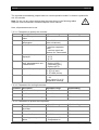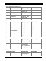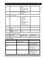
1
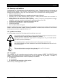
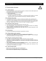
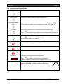
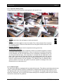
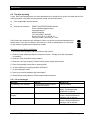
Service Manual
DELI COLD CABINET
DKT-Series
Contents
Page 3
1 Contents
1
2
3
4
5
6
7
Contents ................................................................................................................................... 3
Important references................................................................................................................. 4
2.1 Fundamental Safety Notes................................................................................................. 4
2.2 Warranty and Liabilities ...................................................................................................... 5
2.3 Symbols and Notes ............................................................................................................ 5
2.4 Copyright ............................................................................................................................ 5
2.5 Special safety references ................................................................................................... 6
Introduction ............................................................................................................................... 8
3.1 Introduction ........................................................................................................................ 8
3.2 Special features ................................................................................................................. 8
• Technical details .................................................................................................................... 9
Installation and putting into operation ..................................................................................... 12
4.1 Unwrapping ...................................................................................................................... 12
4.2 Installation ........................................................................................................................ 12
4.3 Electrical connection ........................................................................................................ 12
4.4 Preparation of Using / Starting up .................................................................................... 13
Operation ................................................................................................................................ 14
5.1 Operation elements .......................................................................................................... 14
5.2 Operating the Digital Control ............................................................................................ 15
Maintenance ........................................................................................................................... 16
6.1 Cleaning and care ............................................................................................................ 16
6.2 Trouble shooting .............................................................................................................. 18
6.3 Wiring Diagrams............................................................................................................... 19
6.4 Spare Parts ...................................................................................................................... 20
Service .................................................................................................................................... 25
7.1 Conversions ..................................................................................................................... 25
7.2 Servicing the Digital Control ............................................................................................. 31
Issued: 01/05 Technical changes reserved!
<DKT_Service_e.doc
Important references
Page 4
2 Important references
2.1 Fundamental Safety Notes
2.1.1 Consider notes in the operating manual
Precondition for the safe and trouble free use of this unit is the knowledge of the fundamental
safety notes and safety regulations.
The operating instruction contains the most important references to operate the unit safely.
This operating instruction, particularly the safety references, are to be considered by all persons,
who work on the unit.
Furthermore the rules and regulations to avoid accidents are to be considered.
2.1.2 Obligation of the operator
The Operator is obliged to only let persons work with the unit who:
•
•
are familiar with the fundamental regulations of work safety and accident avoiding and who
have been instructed how to operate the unit.
read and understood the chapter about safety and warning notes and have confirmed this
with their signature.
The safe consious operation of the personnel has to be examined regularly.
2.1.3 Obligation of the personnel
All induviduals who are authorized to work with the unit are obliged to:
•
•
pay attention to the fundamental regulations of work safety and accident avoiding,
read the chapter on work safety and warning notes in this manual and to confirm through their
signature that they have understood these, before actually operating the unit.
2.1.4 Possible risks
Deli Cold Displays are built state of the art and in acknowledgement of all safety related rules.
Nevertheless is it possible that danger for body and lifes of the user and/or third and/or impairments at the unit or at other real values merge. The unit is to be used only :
•
•
for the due use.
in safety related flawless condition.
Disturbances which can hurt the safety are to be eliminated immediately.
2.1.5 Due use
The Deli Cold Displays are built exclusively for the cooling of food only. Any other use of the unit
are only allowed after consulting UBERT GASTROTECHNIK GMBH. Damages which result out of
wrong use UBERT GASTROTECHNIK GMBH cannot be held responsible. Part of the due use is
also:
•
•
the consideration of all references of the operating manual and
the observance of neccessary maintenance and service.
Issued: 01/05 Technical changes reserved!
<DKT_Service_e.doc
Important references
Page 5
2.2 Warranty and Liabilities
Fundamentaly our "General terms of sale and delivery" count. These are known to the operator at
the latest since signing of the contract. Claims to warranty and liability at persons- and property
damages are impossible, if they are to be led back to one or serveral of the following causes:
•
•
•
•
•
•
•
•
Non due use of the unit.
Improper assembling, starting up, operating and servicing of the unit.
Operating the unit with defective safety devices or safety devices which have not been installed properly and are in no working condition.
Disobeyment of the references in the operating manual concerning transportation storage,
installation, start-up, operation, maintenance and assembling of the unit.
Unauthorized mechanical or electrical changes of the unit.
Unsufficient maintenance of wear and tear parts.
Unauthorized repair.
Force of nature and act of god.
Warranty claims can only be forewarded if the guarantee card has been signed and returned to
UBERT GASTROTECHNIK GMBH. Detailed guarantee conditions can be found in the corresponding documentation supplied with the unit.
2.3 Symbols and Notes
In the operating manual the following symbols and signs are used:
This symbol means a possibly or directly threatening danger for the life and the
health of persons and/or a possibly dangerous situation.
Ignoring of these references may result in consequences for your health and/or
can lead to property damages !
This symbol points to important references for the proper use of the unit.
Not paying attention to these references can lead to disturbances at the unit or in
the environment !
This symbol points to operation tips and especially useful information.
Help to use all functions at your unit optimally
2.4 Copyright
The copyright on this operating manual remains at the company UBERT GASTROTECHNIK
GMBH. This operating manual is intended only for the operator and his personal. It contains instructions and references which neither completely nor partially:
• be duplicated
• be circulated or
• be otherwise made available to third parties.
Offences may violate applicable laws.
Issued: 01/05 Technical changes reserved!
<DKT_Service_e.doc
Important references
Page 6
2.5 Special safety references
2.5.1 Safety devices
• Before operating the unit all protective devices as well as all removable parts must
be installed correctly and be fully workable.
• Protective devices may only be removed:
• after stand still and
• prevention of unintentional restart.
• If partial components are delivered, an authorized staff member or service
technician has to execute assembly according to installation guidelines.
2.5.2 Informal safety steps
• The operating manual is to be kept constantly accessible in the operating area.
• In addition to the operating manual all generally acknowledged and all local regulations for accident avoiding and environmental protection have to be applied with.
• All safety- danger labels at the unit are to be kept in readable condition.
2.5.3 Education of the personal
• Only trained and instructed personal may work at the unit.
• The responsibilities of the personal are to be determined clearly for installing,
start-up, operation, assembling, and servicing of the unit.
• During instruction the personal may only work at the unit under supervision of an
experienced person.
2.5.4 Unit-control
• Only instructed personal is allowed to operate the controls.
2.5.5 Safety during regular operation
• The unit is only to operate if all protective devices are fully workable.
• At least once per shift the unit is to be examined with regard to visible damages
and functional ability of the safety devices.
2.5.6 Dangers caused by electric energy
• Any work on the electrical supply is to be executed only by a specialist.
• Likewise the electrical connection of this unit to the power supply must be executed by an electro-specialist; the connection must follow the rules of the local
determinations.
• The electric installation is to be examined regularely. Loose connections and
brased cabels are to be eliminated immediately.
• If works at any life-parts are necessary, a second person who switches off the
main switch if neccessary is to consult.
2.5.7 Special danger-spots
• Remove the cover plate only if unit is switched off!
• Do not touch the refrigerator when unit is switched on!
• Do not touch the evaporator! Danger of injuring oneself!
Issued: 01/05 Technical changes reserved!
<DKT_Service_e.doc
Important references
Page 7
2.5.8 Service and maintenance, troubleshooting
• Prescribed adjustment, service and inspection work is to be accomplished timely
by the manager or if necessary by an authorized service technician.
• The operating personal is to be informed before the beginning of the maintenance
and service work.
• The unit is to be disconnected from the mains before maintaining, inspecting and
repairing is performed; the main switch is to be guarded against unintended reclosing.
• Check all screw connections for tight fitting.
• After finishing maintenance check all safety devices for proper functionality.
2.5.9 Structural changes to the unit
• Do not perform any changes, extensions or conversions to the unit without the
manufacturers permission, especially welding work at supporting parts.
• For all conversions a written permission of the company UBERT
GASTROTECHNIK GMBH is necessary.
• Change all parts of the unit, that are in impropper condition.
• Use only original spare parts.
2.5.10 Cleaning of the unit and disposal of the waste
Used substances and materials are to be handled and disposed appropriately, especially lubricants. Detergents have to follow the rules of food-hygiene.
Issued: 01/05 Technical changes reserved!
<DKT_Service_e.doc
Introduction
Page 8
3 Introduction
3.1 Introduction
All Deli Cold Cabinets are synonymous in
construction and therefore you will have the
possibility of an optimum integration in a complete display conception. An adjustable temperature control enables you to set the desired cooling temperature. We guarantee a
constant temperature even in case of opened
doors. The temperature rises only after some
minutes. The Deli Cold Cabinets show a high
cooling performance. Within the Deli Cold
Cabinets, the cooling convection provides a
stable temperature. The set temperatures are
reached within one hour, the degree of condensation is low.
The maximum holding time depends on the kind of product and on the products
starting temperature. It might be limited by national or local regulations. Never
equip the cabinet with warm or hot products.
3.2 Special features
•
•
•
•
•
•
•
Ergonomic, stylish design
Maximum product visibility by curved front glass
Decorative stand (optional with bag shelf and bumpers)
Easy handling of the curved front glass by pressure lifts
Optimized product-presentation by variable 100mm GN-pan equipment or decorative bowls
Meeting the hygienic requirements in accordance with HACCP
All models are available as self-service equipment for impulse buying
Issued: 01/05 Technical changes reserved!
<DKT_Service_e.doc
Introduction
Page 9
• Technical details
• Dimensions [mm]
DKT 31 and DKT31SS (without stand):
DKT 41 and DKT 41 SS (without stand):
Issued: 01/05 Technical changes reserved!
<DKT_Service_e.doc
Introduction
Page 10
DKT 51 and DKT51SS (without stand):
DKT 71 and DKT 71 SS (without stand):
Issued: 01/05 Technical changes reserved!
<DKT_Service_e.doc
Introduction
3.2.1 Weight
Type
DKT 31
DKT 31SS
DKT 41
DKT 41SS
DKT 51
DKT 51SS
DKT 71
DKT 71SS
Page 11
weight [kg]
app. 153
app. 153
app. 181
app. 181
app. 209
app. 209
app. 265
app. 265
3.2.2 Electrical details
Type
DKT 31
DKT 31SS
DKT 41
DKT 41SS
DKT 51
DKT 51SS
DKT 71
DKT 71SS
electrical connection [EA]
230V, 1/N, 50Hz
230V, 1/N, 50Hz
230V, 1/N, 50Hz
230V, 1/N, 50Hz
230V, 1/N, 50Hz
230V, 1/N, 50Hz
230V, 1/N, 50Hz
230V, 1/N, 50Hz
3.2.3 Noise emission
Type
all types
noise emission
< 70 dB (A)
power
0.68kW
0.68kW
0.78kW
0.78kW
0.88kW
0.88kW
1.1kW
1.1kW
drain [TA]
1 1/2“
1 1/2“
1 1/2“
1 1/2“
1 1/2“
1 1/2“
1 1/2“
1 1/2“
3.2.4 Refridgerant
kind of refrigeration medium for all Cold Display Cabinets: R 134 A
Issued: 01/05 Technical changes reserved!
<DKT_Service_e.doc
Installation and putting into operation
Page 12
4 Installation and putting into operation
In general all Deli Cold Displays will be packed for safe transport after the final control in order to reach you properly. Nevertheless we ask to look at the machine on
arrival to detect any transport damages.
Note! Visible damages have to be reported immediately!
4.1 Unwrapping
• Open the carton and take out the wrapping material carefully.
• Take care that the delivery is complete (see attached freight papers).
4.2 Installation
Place the cabinet in the desired location. Make sure, that is is good visible for your
customer to ensure good foodpresentation and successfull sales.
Take care of the following points:
• Place the Cabinet dry.
• Take care that the Cabinet has to be placed in well ventilated rooms!
• Avoid to place the cabinet close to any heat-sources (heaters, radiators, sunbeams and the like).
• The cooling compartment (condenser and compressor) below the cabinet must
be well ventilated after installation.
• The cabinet (with or without stand) has to be placed on a horizontal level; use a
spirit level if necessary.
• Take care that both sides have at least 10 cm clear space to enable cleaning of
the sideglasses.
• If you have choosen a permanent water drainage, provide a flexible tubeconnection.
• There has to be enough free space to load, unload, clean and maintain the unit.
• The machine has to be placed so that the complete area around it can be
cleaned easily.
4.3 Electrical connection
Note! In general, only service technicians of the company: UBERT GASTROTECHNIK GMBH or service technicians of your responsible service partner are allowed to perform el. connection and other service! All national and lokal rules and
regulations concerning electricity, fireprotection and the like have to be concidered.
During any servicing, take care that the unit is disconnected from the mains! Not
paying attention may result in injury!
Please learn the electrical and technical data of your unit from the nameplate.
•
•
•
•
•
Check whether your lokal electrical power supply is in accordance with the data on the name
plate.
Make sure the supply cable is protected as listed below:
(5- wire, min. cross-section 1,5¨) separatly with 16 Amps.
The power supply needs to be manufactured from flexible cable. It is to be routed to prevent
any contact to hot parts.
The unit is to be connected to the power supply either by means of an appropriate plug or if
connected permanently, a switch (interupting all poles) is to be provided. In case of an emergancy the power supply must be interuptable immediately.
For further information please see the wiring diagram (below).
Issued: 01/05 Technical changes reserved!
<DKT_Service_e.doc
Installation and putting into operation
Page 13
4.4 Preparation of Using / Starting up
Before you can use the Deli Cold Display you have to clean the unit and all removable parts (e. g.
GN-basins) carefully with a grease solvent. Afterwards you have to dry all surfaces.
Note! Do not use flammable cleaners. Do not use high-pressure-, water pressure- or
steam jet- cleaning machines. You will have further information about this in the section ”cleaning and upkeeping”.
After cleaning the Cabinet properly the smell will be minimal when using it the first time.
Issued: 01/05 Technical changes reserved!
<DKT_Service_e.doc
Operation
Page 14
5 Operation
Following you will find explanation and location of all components and their function for the use of
the cabinet.
5.1 Operation elements
Digital Control
Issued: 01/05 Technical changes reserved!
<DKT_Service_e.doc
Operation
Page 15
5.2 Operating the Digital Control
STANDBY button
Switches the cabinet ON and OFF.
LIGHT Button
Switches the lights inside the cabinet ON and OFF.
PPROGRAMMING
button
Keep pushed to change the set temperature using
UP button
.and
Push the UP button for min. 3 seconds to start a defrost cycle
While
ture.
is pushed, use the UP button to increase the set tempera-
DOWN Button
While
is pushed, use the DOWN button to decrease the set temperature. Also used to quit alarms.
COMPRESSOR
Symbol
DEFROST Symbol
Is illuminated whenever the actual temperature is above the set temperature and the compressor is running.
Is illuminated whenever the cabinet is running a defrost cycle
FAN Symbol
Is illuminated whenever the fans are running.
DISPLAY
The DISPLAY shows the actual temperature.
While
is pushed, it shows the set temperature.
While the Cabinet is switched off the display shows “OFF”
Cutting Board:
Workspace to cut your products and do various other handling during loading, unloading, packing and the like.
Note! Do not place hot items on the cutting board.
Issued: 01/05 Technical changes reserved!
<DKT_Service_e.doc
Maintenance
Page 16
6 Maintenance
Following we will show you some advices concerning maintenance, care, trouble shooting and
service for your Deli Cold Display.
6.1 Cleaning and care
6.1.1 Safety advices
•
Before you start to clean and care switch off the appliance and disconnect it
from the mains.
•
Do not use inflammable detergents, sharp-edged or metallic items for cleaning
the unit! Never use high-pressure-, water pressure- or steam jet- cleaning machines!
•
Wear acidproof gloves while cleaning the parts to prevent skin irritations.
6.1.2 General Recommendations
•
The unit has to be cleaned daily.
•
Only use cleaners that are appropriate for food (neutral or alkaline detergents),
even if there are plain and persistent residues.
•
After cleaning with special cleaners you have to wash all parts with clear water
and dry them afterwards so that there are no residues of the cleaner on these
parts.
•
It is absolutely necessary to watch out for some fundamental things to keep this
longliving high-grade-steel-machine working:
- always keep the high-grade-steel surface clean.
- watch out that there is always enough fresh air on the surface
- never contact the surface with rusty material
•
Never use bleaching or chlorine cleaners.
•
Take brushes with plastic or natural bristles for cleaning.
6.1.3 Detergents
To make the cleaning fast and easy we have integrated some cleaners in our program:
•
Intensiv-cleaner:
Detergent for metal- and plastic-surfaces.
•
Glass-cleaner:
Removes fat from glass-surfaces.
•
Stainless steel-cleaner
You have to spray this from a distance of app. 25 cm on the surface and wipe it
off with a dry cleaning rag. If you want to clean only small parts you have to
spray it directly on the cleaning rag and wipe it off this way. With this method it is
possible to clean the Deli Cold Display easily and without stripes.
Issued: 01/05 Technical changes reserved!
<DKT_Service_e.doc
Maintenance
Page 17
6.1.4 Special cleaning hints
Please find below some special cleaning tips for this specific unit:
•
•
•
•
A
B
C
D
E
F
Lamps:
To be cleaned only with soft paper or cloth and alcohol.
Glass:
Lift the curved front glass to clean the inside. Due to the pressure lifts it remains
the desired position. Remove dust and dirt from the glass surface with soft cloth
to avoid scratches.
Drawers, GN-Pans:
Easily removable without tools for seperate cleaning (picture A).
air-openings,evaporator:
All air openings as well as the evaporator need to be cleaned regularly to ensure
convection and cooling performance of the unit and also to minimize prevention
of dirt particles into the fan and lamina of the evaporator. Damages to the unit
can be prevented that way. The evaporator is covered with an evaporator cover
plate. After removing the GN-pans and the air guiding plates this unit can be
lifted and needs to be secured during the cleaning process (We recommend to
involve a second person for this process). The cleaning can be effected with a
vacuum cleaner or a brush. Be careful to prevent injuries or damage of the unit.
Please follow our instructions A-F.
6.1.5 Defrost Cycle
The Deli Cold Cabinet is equipped with a preset defrost cycle. The defrost cycle takes place every
4 hours. During the defrost cycle the compressor is switched off while the fans continue to run.
The defrost cycle runs until a temperature of 5 °C is reached. The length of the defrost cycle is
limited to 30 minutes. If you need to have these settings to be changed, please ask your authorized service technician for guidance.
Issued: 01/05 Technical changes reserved!
<DKT_Service_e.doc
Maintenance
Page 18
6.2 Trouble shooting
If your Deli Cold Display does not work satisfactorily we would like to give a first help with the following checklist. Only after checking these points you should contact:
a)
your responsible service partner
or
b)
directly the company:
UBERT GASTROTECHNIK GmbH
Werk II Gewerbegebiet Nord
Vennekenweg 17
46348 Raesfeld
Tel.:(49) 02865 / 602-226
Service-Tel.:0172 / 2 82 86 31
Fax:(49) 02865 / 602-102 (or -103)
Only these two companies are allowed to carry out service work and replacement of
defect parts. If you do not observe this note or in case of manipulation of a third party any claims for guarantee will become invalid!
Checklist for your Deli Cold Display:
1. Is the unit wired properly and connected to the mains?
2. Does the wall socket provide the required current / voltage (see the nameplate
for details)?
3. Does the fuse protection work properly?
4. Does the unit cool properly? Please check power supply and control!
5. Have you possibly stored hot or warm goods?
6. Is the ventilation of cooling machine sufficient?
7. Is the evaporator iced?
8. Have you correctly adjusted the thermostat?
9. Do all lamps work properly? Check lamps and connection!
6.2.1 Error messages
Message
E0 flashing in the Display
EP in the Display
Means
Temperature probe is short
circuited or broken
Parameters lost
Flashing Temperature in the
Display
Temperature alarm
Beeper sounds
Temperature alarm
Issued: 01/05 Technical changes reserved!
What to do
Call for service
Switch the unit OFF and ON
again; if message reappears,call for service
Quit alarm pushing the DOWN
button; check temperature
settings; call for service
Quit alarm pushing the DOWN
button; check temperature
settings; call for service
<DKT_Service_e.doc
Maintenance
Page 19
6.3 Wiring Diagrams
6.3.1 DKT 31 - 71 and DKT31SS – 71SS 240V / 50Hz / 1/N
Issued: 01/05 Technical changes reserved!
<DKT_Service_e.doc
Maintenance
Page 20
6.4 Spare Parts
Defect parts are to be replaced only by original spare parts of UBERT
GASTROTECHNIK GMBH; the replacement is to be carried out only by their service
personal or by your authorized Service companies. If you do not observe this note or
in case of manipulation of a third party any claims for guarantee will become invalid!
Also all certifications (CE, UL, VDE, GS and the like) become invalid!
6.4.1 Explosion drawing DKT Series
Issued: 01/05 Technical changes reserved!
<DKT_Service_e.doc
Maintenance
Page 21
6.4.2 Spare parts DKT31 and DKT31SS
Amoun Part No.
t
1 121888
2 121869
2 121866
2 121870
1 400500
1 346110
1 346010
1 346109
4 121840
2 121841
3 344131
1 340108
1 340101o
1 340115
1 340128
1 342258
1 342237o
2 460101
2 460002
1 460113
1 460115
1 460011
1 121783
2 421010
2 361508o
Description
VT
cover for evaporator
guide plate
intermediate web
guide rail
discharge with siphon
evaporator- DKT 31
refridgeration unit
filter drier
seal 485mm
seal 110mm
axial fan
lamp 36W
lamp-starter 4-80W
screen capacitor
ballast 36W
Digital Control for KT, KTI, DKT
Temperature probe PT100
Pressure lift 400N, Type 25
lighting screen holder
reflector
acrylic glass cover
Seal, Front for all Deli Series
front glass assy DHT/DKT 31
side glass for DHT/DKT 31/41/51
flange - Teflon, black
Issued: 01/05 Technical changes reserved!
X
<DKT_Service_e.doc
Maintenance
Page 22
6.4.3 Spare parts DKT41 and DKT41SS
Amoun Part No.
t
1 121889
2 121869
2 121866
2 121870
1 400500
1 346110
1 346010
1 346109
4 121840
2 121841
3 344131
1 340108
1 340101o
1 340115
1 340128
1 342258
1 342237o
2 460001
2 460002
1 460113
1 460115
1 460011
1 121549
2 421010
2 361508o
Description
VT
cover for evaporator
guide plate
intermediate web
guide rail
discharge with siphon
evaporator- DKT 31
refridgeration unit
filter drier
seal 485mm
seal 110mm
axial fan
lamp 36W
lamp-starter 4-80W
screen capacitor
ballast 36W
Digital Control for KT, KTI, DKT
Temperature probe PT100
Pressure lift 700N, type 25, DHT/DKT51
lighting screen holder
reflector
acrylic glass cover
Seal, Front for all Deli Series
front glass assy DHT/DKT41
side glass for DHT/DKT 31/41/51
flange - Teflon, black
Issued: 01/05 Technical changes reserved!
X
<DKT_Service_e.doc
Maintenance
Page 23
6.4.4 Spare parts DKT51 and DKT51SS
Amoun Part No.
t
1 121809
1 121844
1 121889
2 121814
4 121847
1 400500
1 346114
1 346011
1 346109
2 121840
2 121841
2 121842
4 344131
1 340114o
1 340101o
1 340115
1 340129
1 342258
1 342237o
2 460001
2 460002
1 460013
1 460015
1 460011
1 121784
2 421010
2 361508o
Description
VT
air guide
guide rail
cover for evaporator
guide plate
intermediate rail for DKT 41/51 cpl.
discharge with siphon
evaporator DKT 51
refridgration unit
filter drier
seal 485mm
seal 110mm
seal 825mm
axial fan
fluorscent lamp 58W
lamp-starter 4-80W
screen capacitor
ballast - 58 W
Digital Control for KT, KTI, DKT
Temperature probe PT100
Pressure lift 700N, type 25, DHT/DKT51
lighting screen holder
reflector
acrylic glass cover
Seal, Front for all Deli Series
front glass assy DHT/DKT 51
side glass for DHT/DKT 31/41/51
flange - Teflon, black
Issued: 01/05 Technical changes reserved!
X
<DKT_Service_e.doc
Maintenance
Page 24
6.4.5 Spare parts DKT71 and DKT71SS
Amoun Part No.
t
1 121809
1 121844
1 121889
2 121814
4 121875
1 121815
1 400500
1 346114
1 346011
1 346109
2 121840
2 121841
2 121842
4 344131
2 340108
2 340101o
2 340115
1 342258
1 342237o
8 460207
2 460113
2,47 460408
2,47 460011
1 121986
2 421107
2 361508o
Description
VT
air guide
guide rail
cover for evaporator
guide plate
intermediate rail for DKT 31 cpl.
intermediate web
discharge with siphon
evaporator DKT 51
refridgration unit
filter drier
seal 485mm
seal 110mm
seal 825mm
axial fan
lamp 36W
lamp-starter 4-80W
screen capacitor
Digital Control for KT, KTI, DKT
Temperature probe PT100
Pressure lift 400N
reflector
acrylic glass cover
Seal, Front for all Deli Series
Frontglas curved DHT/DKT 71, assembly
side glass for DHTG31/41/51/71
flange - Teflon, black
Issued: 01/05 Technical changes reserved!
X
X
X
<DKT_Service_e.doc
Service
Page 25
7 Service
7.1 Conversions
7.1.1 DKT to DKT SS
Unscrew the hexagon socket head screws inside
the clamp panel in order to remove the front window.
Lift the front window out of the clamp panel (do
this always with 2 persons).
Remove the silicon profile from the large front window and put it on the self-service front window.
Observe that you put the the silicon profile on the
correct side.
Issued: 01/05 Technical changes reserved!
<DKT_Service_e.doc
Service
Page 26
Observe that you put the the silicon profile on the correct side.
Insert the self-service front window.
Tigthen the hexagon socket head screws
evenly.
Unscrew the tap bolt of the lifting cylinder (left
and right).
Issued: 01/05 Technical changes reserved!
<DKT_Service_e.doc
Service
Page 27
Picture left: position of tap bolt.
Push out the pin (left and right).
Now you can remove the lifting cylinder from the
support bar (left and right).
Issued: 01/05 Technical changes reserved!
<DKT_Service_e.doc
Service
Page 28
Loosen the fixing screws of the stop profile.
Dismount the stop profile.
Set the air guiding metal plate on the cabinet
front.
Mark the pre-stamped holes on the cabinet front.
Issued: 01/05 Technical changes reserved!
<DKT_Service_e.doc
Service
Page 29
If possible you should weld on the stud bolts and
then fix the air guiding plate by cap nuts.
Or you drill a 3.2 mm Ø hole at the marked point
and fix the air guiding plate by tapping screws.
Finally you have to put on the edge protection on
the side windows (left and right).
Next Step is to retrofit the sliding doors. This is described in the next chapter.
Issued: 01/05 Technical changes reserved!
<DKT_Service_e.doc
Service
Page 30
7.1.2 Retrofit sliding doors
1. Remove the plastic bushes 2. Insert the frame.
top and bottom from each side Note! The frame must close
bracket
precise with the side brackets
at the front.
4. Remove the frame and drill 5. Drill the threads (M4).
holes (Ø3,2 mm) at the marks.
3. Mark the centres of the
bores for the frame‘s fastening through the holes in the
frame on both side brackets.
6. Assemble the frame and fix
it by 4 slotted flat head
screws (M4)
7. Clean and degease the 8. Remove protective foil from
carving board along the air the adhesive tape on the slide
guide rail
rails backside.
Fix the slide rail to the carving
board by pressing it on.
Note: Adjust the slide rail horizontally to the center. Vertically 9. Assemble the sliding doors.
the air guide rail serves as a
stop.
Issued: 01/05 Technical changes reserved!
<DKT_Service_e.doc
Service
Page 31
7.2 Servicing the Digital Control
7.2.1 First level of operation
Parameter Description
S1
Set-Temperature for Deli
Cabinet
Adjustable range
r1...r2
Default setting
2,0 °C
7.2.2 Second level of operation (most frequently used parameters)
Push the UP and DOWN button simultaneously for min. 4 seconds, to reach the second level of operation.
Push the UP / DOWN button to page up / down from one parameter to the next. Push the
PPROGRAMMING button to show the parameter. Push and hold the PPROGRAMMING button
and additionally push the UP / DOWN button to change the parameter.
Here, some of the most frequently used parameters can be set:
Parameter Description
Hysteresis for Compressor
r0
PA
Access to the third level of
operation
Adjustable range
1...15 K
Default setting
2K
-99…+99
-19 (to access to the third
level of operation)
7.2.3 Third level of operation (all parameters)
Push the UP and DOWN button simultaneously for min. 4 seconds, to reach the second level of operation. Page down to parameter “PA”. Enter “-19”. Push the UP and DOWN button again simultaneously for min. 4 seconds, to reach the third level of operation
Push the UP / DOWN button to page up / down from one parameter to the next. Push the
TEMPERATURE button to show the parameter. Push and hold the TEMPERATURE button and
additionally push the UP / DOWN button to change the parameter.
Issued: 01/05 Technical changes reserved!
<DKT_Service_e.doc
Service
Page 32
The controller automatically jumpes back into normal operation mode if no button is pushed for
min. 45 seconds.
Note: Do not use any other settings than the ones shown in the following tables
exept the ones mentioned in selected chapers of this manual!
Here, all parameters can be set:
7.2.3.1 Parameters to specify the controller
Parameter Description
P0
Actual Temperature at
probe
P1
Adjustment of actual
temperature
P4
Use of Probe No. 2
P5
P6
P7
P8
Adjustable range
-99...+9,9 K
(colon not shown)
0: not used
1: used as evaporator
probe
2: used as actual temperature for Thermostat2
Acuracy of temperature
0: no decimal
displayed
1: 0,5°C
2: 0,1°C
0: Fahrenheit (AUS)
Temperature unit - Mes1: Celsius (AUS)
sage displayed while unit
2: Fahrenheit (OFF)
is switched OFF
3: Celsius (OFF)
Type of Temperatureprobe 11: Pt100 (2 wire)
21: PTC (2 wire)
31: PT1000 (2 wire)
Softwarefilter
1: not active
2…32:
mean value of 2 to 32
temperature readings
Default setting
0,0K
0
1
3
11
8
7.2.3.2 Parameters for cooling thermostat:
Parameter Description
r0
Hysteresis for Compressor
Adjustable range
0,1...15,0 K
Default setting
2,0 K
r1
Set-Temperature limit low
-50...r2°C
0°C
r2
Set-Temperature limit high
r1...+150°C
50°C
7.2.3.3 Parameters to protect the compressor:
Parameter Description
c0
Delay after connection to
the mains
c1
Delay after start
Adjustable range
0...240 Min.
Default setting
0 Min.
0...240 Min.
5 Min.
c2
Delay after Stop
0...240 Min.
3 Min.
C3
What happens at probe
failure
0: Compressor off
1: Compressor on
0
Issued: 01/05 Technical changes reserved!
<DKT_Service_e.doc
Service
Page 33
7.2.3.4 Parameters for the defrost cycle:
Parameter Description
d0
Defrosting Intervall
d1
Type of defrosting
d2
Defrosting temperature
Adjustable range
0...99 hours
0 = inactive
0: Electric
1: with hot-gas
-50...+150C
d3
Max defrosting time
1...99 Min.
d6
Displayed temperature dur- 0: Actual Temperature
ing defrosting
1: Last Temp. before
defrosting start
Drainage time
0...15 Min
d7
Default setting
4 hours
30 Min.
0
5,0°C
1
2 Min.
7.2.3.5 Parameters for alarm- and error condition:
Parameter Description
A0
Switching hysteresis for
alarm
A1
Lower limit
A2
Upper limit
A3
Alarm-suppression after
compressor start
Alarm-suppression after
temperature alarm
Alarm-suppression after
defrosting
Behaviour Alarmcontact
A6
A7
A9
Adjustable range
0,1...15,0 K
Default setting
2,0 K
-99,0...0,1 K
0= inactive
0,1...+99,0 K
0= inactive
0...240 Min.
-10,0 K
0...240 Min
2 Min
0...240 Min
15 Min
0: On at alarm
1: OFF at alarm
1
10,0 K
120 Min.
7.2.3.6 Parameters for fan:
Parameter Description
F4
Behavior at defrosting
F5
Delay after defrosting
F7
Function during cooling
Adjustable range
0: Fan off at defrosting
1: Fan on at defrosting
0...240 Min.
1: fan allways on (exept
during defrosting)
2: on, if compressor is
on
3: on, if compressor is
on and F1 >= F2
Default setting
1
0 Min.
1
7.2.3.7 Parameters for Buttons:
Parameter Description
b1
Function of button LIGHT
Adjustable range
Default setting
0: No Function
1: Controller ON/OFF
(StandBy)
2: Settemp. Thermostat2
Issued: 01/05 Technical changes reserved!
<DKT_Service_e.doc
Service
b3
Page 34
3: Direct Relay OFF at
StandBy
4: Direct Relay independent from StandBy
5: Actual Temp.erature
at Probe 2
Function of button StandBy 0: No Function
1: Controller ON/OFF
(StandBy)
4
1
7.2.3.8 Parameters for Relays:
u1
Function of output Relay
K1
u2
Function of output K2
u3
Function of output K3
(if exist)
Function of output K4
(if exist)
Function of output K5
(if exist)
u4
u5
0: No connection
1: Compressor
2: Defrosting
3: Fan (evaporator)
4: Alarm
5: Thermostat 2
6: to button STANDBY
7: to button B
8: No connection
9: ON if controller ON
(see u1)
1
6
(see u1)
3
(see u1)
0
(see u1)
0
Adjustable range
Default setting
7.2.3.9 Parameters for program version:
Parameter Description
PRO
program version
7.2.4 Error messages
Message
E0 flashing in the Display
EP in the Display
Means
Temperature probe is short
circuited or broken
Parameters lost
Flashing Temperature in the
Display
Temperature alarm
Beeper sounds
Temperature alarm
Issued: 01/05 Technical changes reserved!
What to do
Check / change probe
Switch the unit OFF and ON
again; if message reappears,change controller
Quit alarm pushing the
DOWN button; check temperature settings
Check internal of cabinet /
food / compressor
Quit alarm pushing the
DOWN button; check temperature settings
Check internal of cabinet /
food / compressor
<DKT_Service_e.doc
Service
Page 35
Additional information:
In case of an error and in case of an alarm the display flashes. The buzzer sounds and may be
quitted be pushing the DOWN button for minimum 3 seconds.
In case of a temperature-alarm the error message and Temperature display flash alternately.
In case of an error with the temperature probe F1 (cabinet) the compressor runs in a clocked
mode (see parameters c5, c6).
In case of an error with the temperature probe F2 (evaporator) a currently running defrosting cycle will be interrupted and no further defrosting cycle will be started.
Issued: 01/05 Technical changes reserved!
<DKT_Service_e.doc