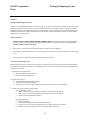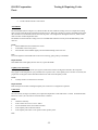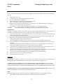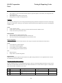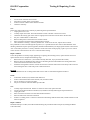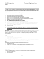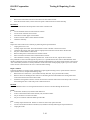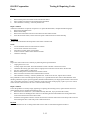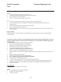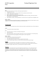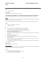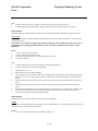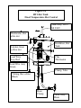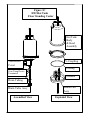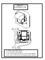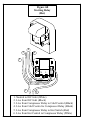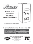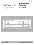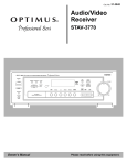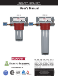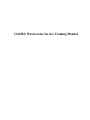
1
OASIS® Watercooler Service Training Manual
Contents
Chapter 1:
Introduction
1.1
Chapter 2:
General Care of the Removable Reservoir Cooler
2.1
Caring for your water cooler
Sanitising your water cooler
Setting up the water cooler at your premises
Installing the water cooler at your customer’s premises
2.1
2.1
2.2
2.3
Chapter 3:
Troubleshooting
3.1
Chapter 4:
Easy Solutions
4.1
Checking the Voltage Received by the Cooler
Matching the Customer’s Needs with the Cooler’s Capacity
Cleaning the Bottle Cooler’s Hot Tank
4.1
4.1
4.2
Testing and Repairing Cooler Parts
5.1
Safety Precautions
Access to Parts Inside the Cooler
Airbell Baffle
Capillary Line and Strainer
Cold Control
Compressor
Condenser
Faucets and Gaskets
Hot Tank and its Components
Hot Tank Switch
Hot Tank Vent Hole
Overload
Refrigerant
Relays
Removable Reservoir
Service Cord
Tubing
Water Bottle
WaterGuard
Wires, Terminals and Connectors
5.1
5.1
5.2
5.2
5.2
5.3
5.4
5.4
5.4
5.14
5.14
5.14
5.14
5.14
5.15
5.15
5.16
5.16
5.17
5.17
Chapter 5:
Appendix A:
Basic Refrigeration Cycle
Components of a Basic Refrigeration System
How the Components Work Together to Form a Refrigeration Cycle
Appendix B:
Exploded Parts Breakdown of OASIS® Bottle Coolers
A.1
A.2
B.1
Diagrams:
Fig 1A
Fig 1B
Fig 2
Fig 3A
Fig 3B
Fig 3C
Fig 3D
Fig 4
Fig 5
Fig 6A
Fig 6B
Fig 7
Fig 8A
Fig 8B
Fig 9
Removable reservoir
Removable reservoir
Location of the cold control
HT1 Hot tank – Fixed temperature hot control
HT1 Hot tank – Adjustable hot control
HT2 Hot tank – Floor Standing Cooler
HT2 Hot tank – Countertop Cooler
Hot tank vent hole
Location of compressor relay
Start relay (cold)
Start relay (hot)
Electrical circuit diagrams
WaterGuard® III assembly
WaterGuard® IV assembly
Basic refrigeration system
OASIS Corporation
Introduction
Chapter 1
Introduction
OASIS Manufacturing Company, founded in 1910 in Columbus, Ohio as the D.A. Ebinger Sanitary Manufacturing
Company, manufactures water coolers for distribution world-wide. OASIS® products, including the OASIS® brand
coolers, are supported by more than 400 authorised service centres. OASIS® quality is a result of rigid standards for
raw materials, precision tooling, efficient manufacturing methods, and extensive testing of all subassemblies and
completed units. OASIS’s distributors maintain a high level of customer service.
This manual is intended for use in OASIS® service training and for reference. It presents aids to troubleshooting
problems, testing and repair instructions, and basic information about refrigeration cycles. Diagrams and schematics
of standard models of OASIS® coolers are provided as examples. The primary emphasis of this manual is the
Removable Reservoir range of bottle water coolers. Although the function of the compressor and possible symptoms
indicating the need for its replacement are discussed in this manual, no compressor replacement instructions are
included inside. Replacement of compressors must be handled by a fully qualified refrigeration repairman.
If you are unfamiliar with how a basic refrigeration cycle works or with standard OASIS® bottle coolers, begin by
referring to the following appendices:
A
B
Basic Refrigeration Cycle
Exploded Parts Breakdown of OASIS® Bottle Cooler
1-1
OASIS Corporation
Cooler
General Care of the Removable Reservoir
Chapter 2
General Care of the Removable Reservoir Cooler
Caring for your water cooler
1.
2.
3.
4.
5.
6.
7.
8.
9.
10.
11.
12.
13.
14.
15.
16.
Do not locate your cooler where the environment would offer any risk of water contamination.
The cooler must be located on a floor which is smooth, level and easily cleaned.
Do not locate the cooler in direct sunlight.
Do not locate the cooler next to a radiator.
Do not locate the cooler within or directly adjacent to toilet facilities.
Do not use the cooler or water bottle as a shelf for plants or objects.
Do not use sprays, mists or vapours around the water cooler.
Do not put any other liquid other than water into the cooler.
Do not touch the nozzles of the faucets.
Do not take water from the faucets if your hands are dirty.
Do not lay the cooler on its side.
Do not leave the cooler without a bottle fitted.
Do not attempt to move the cooler if there is a bottle in place.
When properly installed the water cooler is electrically safe. Even so, do not locate the cooler in constantly
damp areas, beneath dripping pipes, or where water may collect underfoot.
Keep areas around the water cooler free from dirt and rubbish.
The plastic cabinetry should be cleaned using mild soap and water. Do NOT use bleach or any cleaning agents
containing bleach or chlorine.
Sanitising your Water Cooler
Recommended Materials
•
Disposable gloves
•
One time use wipes
•
Mild cleaning agent for outside of cabinet and drip receptor: The following cleaners are acceptable :
Mild soap and water
Fairy Liquid
Fantastik
DO NOT use bleach or any cleaning agents containing bleach or chlorine.
•
Chlorine test kit
2-1
OASIS Corporation
Cooler
General Care of the Removable Reservoir
Sanitisation Procedure
1.
2.
3.
4.
5.
6.
7.
8.
9.
10.
11.
12.
13.
14.
15.
16.
17.
18.
19.
20.
21.
22.
23.
24.
25.
26.
Disconnect the power supply from the cooler
Remove the bottle from the reservoir
Drain water from the reservoir and hot tank (if fitted) through the faucets
Remove the WaterGuard®
Remove the faucets
Disassemble the WaterGuard® and discard the air filter
Remove the baffle
Remove the reservoir
Wash hands thoroughly
Put on disposable gloves
Wash the faucets, WaterGuard® components, baffle and reservoir using mild soap and water.
Rinse with clean water immediately.
Clean the faucets, WaterGuard® components, baffle and reservoir using the sanitising solution. Parts MUST be completely
submerged in the solution
Rinse with clean water immediately
Reassemble the water cooler using the sanitised components
Sanitise hot tank (if fitted) and entire cooler with a new batch of sanitising solution.
Completely fill the cooler with sanitising solution, and let stand for 5 minutes.
Drain solution through hot tank drain tube (if fitted), or through faucets.
Rinse with clean water immediately.
Invert a water bottle on top of the cooler
Flush the reservoir at least three times to remove any traces of the sanitisation material
Use chlorine test kit to identify the presence of any contaminants
If contamination still exists, repeat steps 21 and 22.
Fit the new air filter to the Waterguard®.
Clean the outside of the cabinet and the drip tray using a mild cleaning agent
Reconnect the power supply to the cooler
Setting up the water cooler at your premises
1.
Examine the packaging for signs of damage – report any damage to the haulier.
2.
Remove the carton from the cooler – lie the cooler on its side, cut open the tape sealing the bottom flaps of the
carton and replace the cooler in the upright position. Lift the carton from the cooler.
3.
Remove the shipping bag from the cooler.
4.
Carry out a general inspection of the cooler, ensuring that:
a)
b)
c)
d)
e)
f)
g)
There are no marks or physical damage to the cooler.
That all accessories are present.
That the faucets are tight and in an upright position.
That all the wires and electrical connections are in place at the back of the cooler.
That the cold control is set to the maximum cold position.
That the hot tank switch is in the “OFF” position.
That the cooler is clean and dust free.
2-2
OASIS Corporation
Cooler
General Care of the Removable Reservoir
5.
Sanitise the water cooler.
6.
Replace the shipping bag over the water cooler.
7.
Replace the carton over the top of the cooler.
8.
The cooler is now ready for transportation to the customer’s premises.
Installing the water cooler at your customer’s premises
1.
Carry the cooler in the upright position to the customer’s premises - use the handle at the rear of the unit. DO
NOT LIFT THE UNIT BY THE FAUCETS.
2.
At the customer’s premises, ensure that there are no marks or visible damage to the carton.
3.
Remove the cooler from the carton.
4.
Remove the shipping bag from the cooler.
5.
Carry out a general inspection of the cooler, ensuring that:
a)
b)
c)
d)
e)
f)
g)
There are no marks or physical damage to the cooler.
That all accessories are present.
That the faucets are tight and in an upright position.
That all the wires and electrical connections are in place at the back of the cooler.
That the cold control is set to the maximum cold position.
That the hot tank switch is in the “OFF” position.
That the cooler is clean and dust free.
6.
Place a bottle of water on top of the unit. As soon as the bottle is in place, ensure that the hot faucet is pressed
open and the appropriate time is allowed until the hot tank is full – i.e. water flows out of the hot faucet and air
stops going back into the bottle.
7.
Check that water flows through the cold faucet.
8.
Connect the unit to the electricity supply using the power cord.
9.
Switch on the hot tank and allow the unit to operate for 25 minutes.
10. Using a flash light, check through the back of the cooler for water leaks.
11. After the unit has operated for 25 minutes, check that there is hot water from the hot faucet and cold water from
the cold faucet.
12. Recheck the cooler for water leaks.
13. Ensure that the cooler is in the customer’s desired location, and that all the accessories are attached to the water
cooler.
2-3
OASIS Corporation
Troubleshooting
Chapter 3
Troubleshooting
Discovering the source of a problem is sometimes more difficult and time-consuming than actually resolving the problem.
Chapter 3 presents a troubleshooting chart to help you diagnose problems with OASIS® bottle coolers.
There are two types of problems you may be called upon to correct:
1.
Something is wrong with the cooler. Parts need to be set up correctly, repaired, or replaced.
2.
Nothing is wrong with the cooler. The cooler is not getting power or it is receiving power at the wrong voltage, the
cooler is being expected to perform beyond its capability, or the cooler simply needs to be cleaned.
The troubleshooting chart lists common symptoms (such as “water too cold or frozen”) and the conditions or parts that may
be causing the symptoms. Refer to Chapter 5, Testing and Repairing Cooler Parts, for instructions on testing, repairing, and
replacing specific parts that may be causing the problem.
Chapter 4, Easy Solutions, discusses three remedies for common problems that do not require repair work (power source,
capacity, and cleaning).
3-1
OASIS Corporation
Troubleshooting
Troubleshooting Chart for Bottle Coolers
Symptom
Solution Checklist
Page
No cold water and compressor
not running
1. Check voltage received by cooler
2. Check cold control
3. Check wires
4. Check compressor relay
5. Check compressor overload
6. Check compressor
4.1
5.3
5.21
5.19
5.18
5.4
No cold water and compressor
running
1. Check voltage received by cooler
2. Check for a refrigerant leak
3. Check for a restriction in capillary line
or strainer
4. Check compressor
4.1
5.18
5.2
Water too cold or frozen
1. Check cold control
2. Check for a refrigerant leak
5.3
5.18
Unit runs noisily
1. Check for vibrations caused by loose screws
2. Check for vibrations at refrigeration lines
3. Check compressor
5.4
No hot water
1. Is switch for hot tank turned off?
2. Check voltage received by cooler
3. Check heat limiter
4. Check hot control
5. Check wires
6. Check hot tank heating element
5.17
4.1
5.5
5.5
5.21
5.5
No water flow from hot faucet
1. Is water bottle empty?
2. Check hot faucet
3. Check for mineral build-up in hot tank
5.5
4.2
3-2
5.4
OASIS Corporation
Troubleshooting
Troubleshooting Chart for Bottle Coolers (continued)
Symptom
Solution Checklist
Page
Hot water too hot or boiling over
1. Has tank been bled of air
2. Check hot control
3. Check for mineral build-up in hot tank
4. Check for plugged hot tank vent hole
2.2
5.5
4.2
5.17
Water leaks
1. Check for cracked plastic bottle
2. Check for damaged reservoir
3. Check for loose faucet or damaged gasket
4. Check hot tank inlet seal
5. Check hot faucet fitting
6. Check hot tank drain fittings
7. Check hot tank for damage
5.21
5.19
5.5
5.5
5.5
5.5
5.5
Oil on refrigerant lines
1. Unplug service cord
2. Contact refrigeration repairman
3-3
OASIS Corporation
Easy Solutions
Chapter 4
Easy Solutions
Some problems have simple solutions. This chapter describes three cases in which a cooler is not meeting a
customer’s needs, but nothing is wrong with the cooler. In the first case, the cooler is not receiving the correct
voltage. In the second case, the capacity of the cooler is inadequate for the customer’s requirements, and in the third
case, the cooler simply needs to be cleaned.
Checking the Voltage Received By the Cooler
The easiest solution to a non-working cooler may be to plug the cooler’s service cord into an electrical outlet.
Although most solutions are not usually this simple to find, do not be lulled into forgetting to check this possible
cause of trouble.
Check
•
•
Is the service cord plugged in?
Is the switch controlling the outlet in the OFF position?
Test
1. Plug in the cooler.
2. Make sure any switch controlling the outlet is in the ON position.
Remove the service cord from the wall outlet and plug in a portable radio or similar device. If the radio works, the
outlet is good.
Repair / Solution
Incorrect voltage through the outlet may need to be corrected by the local utility company. Contacting the utility is
the responsibility of the customer.
Matching the Customer’s Needs with the Cooler’s Capacity
Under normal conditions, most bottle coolers will produce 4.5 litres of cold water (< 10ºC) per hour and a little more
than nine litres of hot water (80º - 90ºC) per hour.
Check
•
•
•
Room temperature. If the temperature of the room containing the cooler or the temperature of the water in the
cooler’s water bottle is above 32ºC, the cooler will not be able to provide as much cold water within the
standard amount of time.
Amount of hot/cold water required in an average hour. Find out how many persons use the cooler each hour
and what size cups they are filling. Calculate the total amount of water required in an average hour.
Special customer needs for large amounts of water during certain periods of the day. For example, does the
customer need nine litres of cold water at 12.45 each afternoon to fill pitchers for meeting rooms? Does the
customer need eighteen litres of hot water early each day when coffee or tea is prepared?
Repair/ Solution
If a customer’s demands are exceeding the cooler’s capabilities, suggest adding another cooler.
4-1
OASIS Corporation
Easy Solutions
Cleaning the Bottle Cooler’s Hot Tank
The use of some types of water may eventually cause a build-up of mineral deposits on the inside of the hot tank.
These mineral deposits insulate the water in the tank from the hot control and prevent the hot control from sensing
the hot water temperature.
Bottle water coolers need to be cleaned periodically to prevent this mineral build-up inside the heating tank. The
frequency of cleaning is determined by the quantity of minerals in the bottle water and the amount of water used.
Heating tanks may require cleaning when:
1. Normal hot water flow appears restricted.
2. Noisy heating cycles are heard.
3. Water in the cooling tank is very warm.
4. Mineral build-up has imparted a taste to the water.
Offer your customers hot tank cleaning whenever a cooler must be brought in for repairs. Even though mineral buildup and corrosion are not covered under OASIS warranties, many customers will want this preventive maintenance,
which will extend the life of the cooler.
Instructions for cleaning the hot tank are listed on the following pages.
Recommended Materials
•
•
•
•
Hot Tank de-scaling solution : Dissolve 125 grams of citric acid crystals in 1 litre of hot water
Bucket or pan with 8 - 10 litre capacity
Funnel with 8mm diameter end
Rubber gloves
Repair/ Solution
1.
2.
3.
4.
5.
6.
7.
8.
9.
10.
11.
12.
13.
Disconnect the power supply cord.
Draw water from the hot faucet until the water is cool.
Remove the bottle from the unit.
CAUTION: A nearly full bottle of water weighs over forty pounds ( 18.1 kg ) and can be awkward to handle. It
may be necessary for you to drain water from the bottle until it becomes manageable.
Drain water from the reservoir through the cold faucet.
Place a bucket or pan under the black drain valve located at the rear of the cooler.
Turn the valve’s petcock counter clockwise to open. CAUTION: HOT WATER CAN SCALD HANDS.
Turn the drain valve to a closed position when the tank is empty.
For easy access to the hot tank inlet tube, remove the reservoir by unscrewing the cold faucet ( blue handle )
and pulling upward on the reservoir’s lip.
Remove the baffle from the reservoir.
Place a funnel with an 8 mm diameter end into the supply tube.
Mix 125 grams of citric acid crystals with one litre of very hot water.
( wearing rubber gloves is recommended )
Carefully pour the hot solution into the funnel. BE CAREFUL NOT TO SCALD YOUR HANDS.
Replace the removable reservoir and the cold faucet.
4-2
OASIS Corporation
14.
15.
16.
17.
18.
19.
20.
21.
22.
23.
24.
25.
Easy Solutions
Fill the reservoir with bottled water until the water level is 75 mm from the top. To allow the hot tank to fill, open
the hot faucet until the water begins to flow, then close the faucet.
Plug the service cord into the wall socket.
Let the unit stand for at least twenty minutes.
While the citric acid solution is cleaning the hot tank, this is a good time to clean the rest of the unit.
Inspect the back of the unit for lint or dirt on the wire and tube condenser. If it is dirty, clean it with a non-wire
stiff brush or a vacuum cleaner.
Unplug the service cord.
Using rubber gloves and taking care not to scald your hands, draw water from the hot faucet until the flow
ceases. Open the heating tank drain, catching the water in a pan or bucket. The water will be discoloured. This
drain water should be immediately poured down a drain to prevent accidental spilling; this water will stain.
Pour at least 4.5 litres of bottled water into the cooling reservoir and allow this water to drain from the heating
tank drain. Drain any remaining water in the reservoir through the cold faucet.
Turn the drain valve to a closed position when the hot tank is empty.
Replace the baffle and place a bottle of water on the unit. Open the hot faucet to allow the tank to fill.
Plug the service cord back into the wall socket.
After the unit has run for ten to fifteen minutes, draw at least one litre of water from both hot and cold faucets.
Your heating tank should now be clean. If the flow of water or the noisy cycles have not been improved, you should
have the unit repaired at an authorised service centre.
Cleaning the unit in this manner will not only make the unit run more efficiently, but will make the water taste better.
4-3
OASIS Corporation
Parts
Testing & Repairing Cooler
Chapter 5
Testing and Repairing Cooler Parts
Chapter 5 provides detailed instructions on how to inspect, test, repair, and replace the OASIS® cooler parts you will
most frequently be required to service. Use the troubleshooting chart provided in Chapter 3 to diagnose potential
problems, then refer to this chapter for specific information about each part mentioned in the troubleshooting chart.
OASIS® cooler parts are organised alphabetically in this chapter. Review the following safety precautions before
beginning service on any cooler.
Safety Precautions
1.
ALWAYS UNPLUG THE COOLER BEFORE WORKING ON IT. The water coolers described in this manual
operate on either 115 volts, 60 hertz single phase, or on 220/240 volts, 50/60 hertz single phase. Every effort
should be made to avoid electric shock.
2.
When using a volt/ohm meter in the Ohms mode, be sure the cooler is unplugged.
3.
When using a volt/ohm meter in the AC volts mode, be sure the meter is set on a level sufficient for the voltage
in use.
4.
Check to be sure the outlet provides the voltage required by the cooler.
Access to parts inside the cooler
Before beginning the service inspection and/or repair, you will need to remove the cooler chassis from the cabinet.
The steps below outline the procedure for all removable reservoir coolers. To replace the chassis inside the cabinet,
reverse the instructions.
1. Drain the water from the cooler
• Remove the bottle from the reservoir
• Drain water through the faucets
2. Remove the reservoir
• Lift off WaterGuard® assembly (if fitted)
• Remove faucets and faucet gaskets
• Grasp the top of the reservoir around the opening and pull upwards in a straight motion.
3. Remove the cooler chassis from the cabinet
A. Floor Standing Coolers
• Remove the two screws attaching the metal shelf of the cooler to the cabinet
• Remove the two screws attaching the metal base of the cooler to the cabinet
• Lift the cooler chassis from the cabinet
B. Countertop Coolers
• Remove the drip tray
• Unsnap the drain plug from the base (Hot model only)
• Lie the cooler on its side and pull off the base (it is simply snapped into position)
• Remove the 4 screws fixing the cabinet to the metal base of the cooler
5-1
OASIS Corporation
Parts
•
Testing & Repairing Cooler
Lift the cabinet from the cooler chassis
Airbell Baffle
The airbell baffle (shown in Figure 1A) controls the flow of water inside the cooling reservoir. It disperses incoming
water evenly around the probe at the bottom of the reservoir. When the cold faucet is opened, the baffle ensures that
the water flows out of the tank from the area near the probe - not straight down through the reservoir, which would
result in a flow of room temperature water.
The baffle is located inside the cooling reservoir. The baffle tube should sit securely on the moulded fitting in the
reservoir.
Check
•
Has the baffle been removed from the cooler?
•
Is the baffle in the correct place?
•
Does the tube on the baffle fit tightly onto the moulded fitting in the reservoir?
Test
To test the tightness of the baffle tube in the reservoir fitting, gently pull up on the baffle.
Repair/Solution
If the baffle does not fit tightly into the reservoir, replace the baffle.
Capillary Line and Strainer
The capillary line (tube) and strainer (see figure 9) measure the amount of refrigerant released to the evaporator.
They appear in the refrigeration cycle just before the evaporator coils. If the capillary line or strainer is restricted, the
proper flow of refrigerant will be disturbed and the water will not be adequately cooled.
Check
•
Visually check to see that lines are not bent.
Repair/Solution
Refer the repair of a broken or damaged capillary line or strainer to a refrigeration repairman.
Cold Control
The cold control (see figure 2) enables you to adjust the temperature to which the water is cooled. On all Removable
Reservoir coolers, the cold control is attached to the condenser.
Check
•
Check for continuity
•
Is the control set too low or set to “OFF”?
•
Are the terminals of the control bent or broken
•
Is the capillary tube cracked or broken?
•
Is the capillary tube in the correct position in the capillary well?
Test
5-2
OASIS Corporation
Parts
Testing & Repairing Cooler
Test for continuity by following the steps listed below (Note: The cold control capillary tube must be warm during
this test):
1.
2.
3.
4.
5.
6.
Unplug the service cord.
Visually inspect the control. See if the terminals are loose.
Set your volt/ohm meter to ohms mode.
Remove both positive and neutral wires from the cold control.
Place one meter test lead to each cold control terminal.
If the meter shows a reading, continuity exists and the control is good. If the meter shows no reading, no
continuity exists and the control must be replaced.
7.
If continuity exists, gently move the terminals back and forth to see if continuity is broken.
CAUTION:
Never bend terminals, since bending could change the calibration of the control.
Repair/Solution
A defective cold control is replaced, not repaired. All cold controls used by OASIS work in the same way. However,
some have an OFF switch and others do not. To replace the control, complete the steps listed below:
1.
Locate the capillary tube. It is aluminium and comes out of the side or bottom of the cold control and goes into
a copper tube built into the probe assembly.
2.
Place a piece of masking tape around the capillary tube at the point the tube enters the copper capillary well.
3.
Remove the wires and the two mounting screws from the old cold control.
4.
Gently pull the capillary tube out of the capillary well.
5.
Carefully straighten the capillary tube over the new control. Do not kink or break the capillary tube.
6.
Place the old and new controls and capillary tubes side by side, with the sensing ends of the controls next to
each other.
7.
Transfer the masking tape from the old capillary tube to the new one. Using this method will enable you to
insert the new capillary the same distance into the capillary well as the old tube.
8.
Gently insert the new capillary tube into the capillary well until the masking tape is at the end of the well. If
necessary, lubricate the tube with a small amount of oil before inserting it into the well.
9.
Attach the new cold control to the condenser with the two mounting screws, being careful to keep the capillary
tube away from the condenser and hot tank (when cooler is equipped with a hot tank).
10. Attach the wires to the terminals. Be sure not to attach power wires to ground terminals.
11. Turn the adjusting screw to the “MAX” cold position.
12. Check the operation of the cooler.
Compressor
The compressor (see figure 9), or pump, serves two functions. It compresses the low-pressure, low-temperature gas
into a high pressure, high-temperature gas and it keeps the refrigerant flowing through the cycle.
CAUTION: Under no circumstances are you to attempt to replace or repair the compressor. The refrigeration
system, including all refrigerant lines, may be serviced only by a fully certified refrigerant repairman. Only original
equipment replacement parts provided by OASIS Manufacturing Company should be used for OASIS water coolers.
CAUTION: Whenever you suspect problems with the compressor, immediately unplug the cooler. This action may
prevent serious damage to the compressor or the refrigeration system.
Check
Immediately unplug the cooler and refer the repair to a refrigeration repairman in any of the following cases:
•
The compressor runs but does not cool the water. (The unit may be low on refrigerant).
5-3
OASIS Corporation
Parts
•
•
•
Testing & Repairing Cooler
The compressor runs a short time and shuts off, then repeats the pattern several times. (The refrigerant lines
may be restricted.)
The compressor runs and will not shut off.
Refrigerant oil is visible on a refrigerant line.
Condenser
The condenser (See figure 9) receives hot pressurised refrigerant gas from the compressor and cools it until the gas
changes to a liquid state. In doing so, the condenser transfers heat from the refrigerant into the air surrounding the
condenser coils.
Check
•
Is the condenser clean?
•
Is the cooler so close to the wall that it restricts air flow around the condenser coils?
•
Is the cooler near any other heat source?
Repair/Solution
1.
Remove any dirt or grease from the cooler.
2.
Leave at least two inches between the cooler and the wall.
3.
Move any other heat-generating appliance away from the cooler.
Faucets and gaskets
The faucets control the flow of water from the cooler. They are located on the outside front of the cooler.
Check
•
Are the faucets screwed in tightly?
•
Are the faucet threads stripped?
•
Are the gaskets worn, cracked or broken?
•
Is water dripping from around the faucets?
Test
1.
Remove faucets
2.
Inspect faucets, threads and gaskets
Repair/Solution
If defects are found then replace the relevant faucet or gasket, being careful not to over tighten the faucet. Do not
use Teflon tape on the faucet threads.
Hot Tank Assembly and its Component
The hot tank holds water as it is being heated and stores it until it is released through the hot faucet. There are four
different hot tank assemblies that have been used on Removable Reservoir Coolers. Refer to figure 3 to identify the
type of hot tank that is installed in your cooler.
Fig
3a
3b
Construction
One piece stainless
One piece stainless
3c
Two piece stainless
Type of Hot Control
Fixed temperature
Adjustable temperature – gas
filled
Adjustable temperature – oil filled
5-4
Type of Heat Limiter
Resettable button
Resettable button
Where Used
B1RR / B1SR
B1RR / B1SR
Non-resettable thermal link
B1RR / B1SR
OASIS Corporation
Parts
3d
Two piece stainless
Testing & Repairing Cooler
Adjustable temperature – oil filled
Non-resettable thermal link
B1RCT
A. One Piece Stainless Steel Hot Tank with Fixed Temperature Control & Resettable Limiter.
Heat Limiter
The heat limiter prevents dangerous overheating of the cooler. The resetable heat limiter consists of a bi-metal disk
that bends when heated above 90ºC, breaking electrical contact. When the heat limiter cools to approximately 45ºC,
manually push the reset button and the limiter will work again.
CAUTION: Use of the heat limiter is an Underwriters Laboratory requirement. Any attempt to bypass this part will
result in the loss of warranty coverage.
Check
•
Check for continuity
•
Are the terminals of the heat limiter bent or broken?
•
Are the wires of the heat limiter loose?
Note: Operating the cooler when the hot tank is not completely full of water with all air bled off will cause the heat
limiter to break electrical contact. When this occurs, push the reset button.
Test
Inspect the heat limiter and test for continuity by following the steps listed below:
1.
Unplug the service cord.
2.
Visually inspect the heat limiter. See if the terminals are bent or broken or the wires are loose.
3.
Set your volt/ohm meter to ohms mode.
4.
Remove both positive and neutral wires from the heat limiter.
5.
Place one meter test lead on each terminal of the heat limiter.
6.
There should be a reading - continuity should exist. Try to reset the limiter. If continuity still does not exist,
replace the heat limiter.
Repair / Solution
A defective heat limiter is replaced, not repaired. To replace the heat limiter, complete the following steps:
1.
Remove the heat limiter wires.
2.
Remove the screws holding the heat limiter to the hot tank bracket.
3.
Screw the new heat limiter to the hot tank and connect the positive and neutral wires.
Hot Control
The hot control determines the temperature of the water in the hot tank.
Check
•
Are the terminals of the hot control bent or broken?
•
Are the wires of the hot control loose?
•
Does the hot control appear to be broken?
•
Is the hot control in firm contact with the hot tank?
•
Check for continuity.
Test
Inspect the control and test for continuity by following the steps listed below:
1.
Unplug the service cord.
2.
Visually inspect the control. See if the terminals are bent or broken or the wires are loose.
5-5
OASIS Corporation
Parts
Testing & Repairing Cooler
3.
Check the tightness of the two mounting screws to ensure that the control makes good contact with the body
of the tank. Replace any screws with stripped or damaged threads..
4.
Set your volt/ohm meter to ohms mode.
5.
Remove both positive and neutral wires from the control.
6.
Place one meter test lead on each terminal of the hot control.
7.
There should be a reading - continuity should exist. If this is not the case, replace the hot control.
If no problems are discovered through the steps above, it is possible that the hot control is mis-calibrated. Since
checking calibration requires special equipment, OASIS recommends that you simply replace the hot control with a
“test” control that you know is correctly calibrated. If the cooler then works properly, replace your “test” control
with a new hot control and save the “test” control for future testing.
Repair / Solution
Unless the problem is solved by simply tightening or replacing the mounting screws, replace the hot control.To
replace the hot control, complete the following steps:
1.
Remove the hot control wires. (You will have already done this, if you just tested the control)
2.
Remove the screws holding the hot control to the hot tank
3.
Screw the new hot control to the hot tank and connect the positive and neutral wires. Be careful not to over
tighten the mounting screws. Doing so will strip the threads and allow the control to move away from the wall
of the hot tank.
Hot Tank
The hot tank holds water as it is being heated and stores it until it is dispensed through the hot faucet.
Check
•
Is the heater element (coil) of the hot tank defective?
•
Is there a short between the heater element (coil) and the hot tank?
•
Do you see holes or cracks in the tank?
•
Do you see evidence of mineral build-up in the tank?
Test
1.
2.
3.
4.
5.
6.
Visually inspect the hot tank. If holes or cracks are discovered, replace the tank.
Test for a short between the heat element (coil) and the hot tank by following the steps listed below:
Unplug the cooler.
Place one meter test lead on one of the heat element terminals.
Place the other meter test lead on the tank.
If there is a reading, there is a short circuit between the heating element and the tank, and the element or tank
must be replaced.
Repair / Solution
If mineral build-up is evident, clean the hot tank following the procedure listed in Chapter 4 (Cleaning the Bottle
Cooler Hot Tank).
CAUTION: Extreme care must be exercised in rinsing the tank to remove all acid or chemical cleaners. Be sure to
open the hot tank drain and to rinse the drain line as well as the tank. Test the tank water with litmus paper before
reusing the tank.
To remove and replace the hot tank, follow the steps listed below:
1.
Drain the hot tank through the drain valve assembly.
2.
Remove the cooler chassis from the cabinet (see pg 5.1)
3.
Disconnect the earth wire from the cooler base.
4.
Disconnect the red fused lead wire from the heat limiter.
5-6
OASIS Corporation
Parts
5.
6.
7.
8.
9.
10.
11.
12.
Testing & Repairing Cooler
13.
14.
Disconnect the white neutral lead wire from the thermostat.
Remove the two screws attaching the drain valve assembly to the condenser.
Remove the two screws attaching the hot tank to the shelf and lift out the hot tank assembly.
Pull the new hot tank up into position under the shelf.
TIP : Attach the earth wire to the hot tank before installation.
Attach the tank to the shelf with two screws.
A new hot control and heat limiter are provided with the replacement tank.
Attach wires to heat limiter and hot control. (Refer to the electrical diagram on the back page of the Service
Instruction for the cooler you are repairing). This schematic is also displayed on the inside of the cooler.
Refit the drain valve assembly to the condenser.
Check for water leaks.
B.
One Piece Stainless Steel Hot Tank with Adjustable Temperature Control & Resettable Limiter.
Heat Limiter
The heat limiter prevents dangerous overheating of the cooler. The resettable heat limiter consists of a bi-metal disk
that bends when heated above 90ºC, breaking electrical contact. When the heat limiter cools to approximately 45ºC,
manually push the reset button and the limiter will work again.
CAUTION: Use of the heat limiter is an Underwriters Laboratory requirement. Any attempt to bypass this part will
result in the loss of warranty coverage.
Check
•
Check for continuity
•
Are the terminals of the heat limiter bent or broken?
•
Are the wires of the heat limiter loose?
Note: Operating the cooler when the hot tank is not completely full of water with all air bled off will cause the heat
limiter to break electrical contact. When this occurs, push the reset button.
Test
Inspect the heat limiter and test for continuity by following the steps listed below:
1.
Unplug the service cord.
2.
Visually inspect the heat limiter. See if the terminals are bent or broken or the wires are loose.
3.
Set your volt/ohm meter to ohms mode.
4.
Remove both positive and neutral wires from the heat limiter.
5.
Place one meter test lead on each terminal of the heat limiter.
6.
There should be a reading - continuity should exist. Try to reset the limiter. If continuity still does not exist,
replace the heat limiter.
Repair / Solution
A defective heat limiter is replaced, not repaired. To replace the heat limiter, complete the following steps:
1.
Remove the heat limiter wires.
2.
Remove the screws holding the heat limiter to the hot tank bracket.
3.
Screw the new heat limiter to the hot tank and connect the positive and neutral wires.
Hot Control
The hot control determines the temperature of the water in the hot tank.
Check
•
Are the terminals of the hot control bent or broken?
5-7
OASIS Corporation
Parts
•
•
•
•
Testing & Repairing Cooler
Are the wires of the hot control loose?
Does the hot control appear to be broken?
Is the hot control in firm contact with the hot tank?
Check for continuity.
Test
Inspect the control and test for continuity by following the steps listed below:
1.
Unplug the service cord.
2.
Visually inspect the control. See if the terminals are bent or broken or the wires are loose.
3.
Check that the sensing part of the control is tightly inserted into the relevant tube in the hot tank.
4.
Set your volt/ohm meter to ohms mode.
5.
Remove both positive and neutral wires from the control.
6.
Place one meter test lead on each terminal of the hot control.
7.
There should be a reading - continuity should exist. If this is not the case, replace the hot control.
If no problems are discovered through the steps above, it is possible that the hot control is miscalibrated. Since
checking calibration requires special equipment, OASIS recommends that you simply replace the hot control with a
“test” control that you know is correctly calibrated. If the cooler then works properly, replace your “test” control
with a new hot control and save the “test” control for future testing.
Repair / Solution
Unless the problem is solved by simply tightening or replacing the mounting screws, replace the hot control. To
replace the hot control, complete the following steps:
1.
Remove the hot control wires. (You will have already done this, if you just tested the control)
2.
Remove the screws holding the hot control to its mounting bracket and withdraw the sensing bulb of the
control from the relevant tube in the hot tank
3.
Install the sensing bulb of the new control into the tube on the hot tank and screw the body of the control to
the mounting bracket. Connect the positive and neutral wires.
Hot Tank
The hot tank hold water as it is being heated and stores it until it is released through the hot faucet.
Check
•
Is the heater element (coil) of the hot tank defective?
•
Is there a short between the heater element (coil) and the hot tank?
•
Do you see holes or cracks in the tank?
•
Do you see evidence of mineral build-up in the tank?
Test
1.
2.
3.
4.
5.
6.
Visually inspect the hot tank. If holes or cracks are discovered, replace the tank.
Test for a short between the heat element (coil) and the hot tank by following the steps listed below:
Unplug the cooler.
Place one meter test lead on one of the heat element terminals.
Place the other meter test lead on the tank.
If there is a reading, there is a short circuit between the heating element and the tank, and the element or tank
must be replaced.
Repair / Solution
If mineral build-up is evident, clean the hot tank following the procedure listed in Chapter 4 (Cleaning the Bottle
Cooler Hot Tank).
5-8
OASIS Corporation
Parts
Testing & Repairing Cooler
CAUTION: Extreme care must be exercised in rinsing the tank to remove all acid or chemical cleaners. Be sure to
open the hot tank drain and to rinse the drain line as well as the tank. Test the tank water with litmus paper before
reusing the tank.
To remove and replace the hot tank, follow the steps listed below:
1.
Drain the hot tank through the drain valve assembly.
2.
Remove the cooler chassis from the cabinet (see pg 5.1)
3.
Disconnect the earth wire from the cooler base.
4.
Disconnect the red fused lead wire from the heat limiter.
5.
Disconnect the white neutral lead wire from the thermostat.
6.
Remove the two screws attaching the drain valve assembly to the condenser.
7.
Remove the two screws attaching the hot tank to the shelf and lift out the hot tank assembly.
8.
Pull the new hot tank up into position under the shelf.
9.
TIP : Attach the earth wire to the hot tank before installation.
10. Attach the tank to the shelf with two screws.
11. A new hot control and heat limiter are provided with the replacement tank.
12. Attach wires to heat limiter and hot control. (Refer to the electrical diagram on the back page of the Service
Instruction for the cooler you are repairing). This schematic is also displayed on the inside of the cooler.
13. Refit the drain valve assembly to the condenser.
14. Check for water leaks.
C.
Two Piece Stainless Steel Hot Tank with Adjustable Temperature Control & Non-resettable Limiter (Floor
Standing Coolers).
Heat Limiter
The heat limiter used is a thermal link which breaks if the temperature of the hot tank exceeds a set limit. It is a “single
use” device – if it operates, it needs to be replaced before the hot tank can be used. CAUTION: Use of the heat
limiter is an Underwriters Laboratory requirement. Any attempt to bypass this part will result in the loss of
warranty coverage.
Check
•
Check for continuity
•
Are the terminals of the heat limiter bent or broken?
•
Are the wires of the heat limiter loose?
Note: Operating the cooler when the hot tank is not completely full of water with all air bled off will cause the heat
limiter to break electrical contact. When this occurs, the heat limiter must be replaced.
Test
Inspect the heat limiter and test for continuity by following the steps listed below:
1.
Unplug the service cord.
2.
Visually inspect the heat limiter. See if the terminals are bent or broken or the wires are loose.
3.
Set your volt/ohm meter to ohms mode.
4.
Remove both positive and neutral wires from the heat limiter.
5.
Place one meter test lead on each terminal of the heat limiter.
6.
There should be a reading - continuity should exist.
Repair / Solution
A defective heat limiter is replaced, not repaired. To replace the heat limiter, complete the following steps:
1.
Remove the heat limiter wires.
2.
Remove the P-clamp
5-9
OASIS Corporation
Parts
3.
4.
Testing & Repairing Cooler
Remove the heat limiter from its location tube in the base of the hot tank.
Insert the new heat limiter, and reconnect the positive and neutral wires and the P-clamp.
Hot Control
The hot control determines the temperature of the water in the hot tank.
Check
•
Are the terminals of the hot control bent or broken?
•
Are the wires of the hot control loose?
•
Does the hot control appear to be broken?
•
Is the hot control in firm contact with the hot tank?
•
Check for continuity.
Test
Inspect the control and test for continuity by following the steps listed below:
1.
Unplug the service cord.
2.
Visually inspect the control. See if the terminals are bent or broken or the wires are loose.
3.
Check that the sensing part of the control is tightly inserted into the relevant tube in the hot tank.
4.
Set your volt/ohm meter to ohms mode.
5.
Remove both positive and neutral wires from the control.
6.
Place one meter test lead on each terminal of the hot control.
7.
There should be a reading - continuity should exist. If this is not the case, replace the hot control.
If no problems are discovered through the steps above, it is possible that the hot control is miscalibrated. Since
checking calibration requires special equipment, OASIS recommends that you simply replace the hot control with a
“test” control that you know is correctly calibrated. If the cooler then works properly, replace your “test” control
with a new hot control and save the “test” control for future testing.
Repair / Solution
Unless the problem is solved by simply tightening or replacing the mounting screws, replace the hot control.To
replace the hot control, complete the following steps:
1.
Remove the hot control wires. (You will have already done this, if you just tested the control)
2.
Remove the screws holding the hot control to its mounting bracket and withdraw the sensing bulb of the
control from the relevant tube in the hot tank
3.
Install the sensing bulb of the new control into the tube on the hot tank and screw the body of the control to
the mounting bracket. Connect the positive and neutral wires.
Hot Tank
The hot tank holds water as it is being heated and stores it until it is released through the hot faucet.
Check
•
Is the heater element (coil) of the hot tank defective?
•
Is there a short between the heater element (coil) and the hot tank?
•
Do you see holes or cracks in the tank?
•
Do you see evidence of mineral build-up in the tank?
Test
1.
Visually inspect the hot tank. If holes or cracks are discovered, replace the tank.
2.
Test for a short between the heat element (coil) and the hot tank by following the steps listed below:
3.
Unplug the cooler.
5-10
OASIS Corporation
Parts
4.
5.
6.
Testing & Repairing Cooler
Place one meter test lead on one of the heat element terminals.
Place the other meter test lead on the tank.
If there is a reading, there is a short circuit between the heating element and the tank, and the element or tank
must be replaced.
Repair / Solution
If mineral build-up is evident, clean the hot tank following the procedure listed in Chapter 4 (Cleaning the Bottle
Cooler Hot Tank).
CAUTION: Extreme care must be exercised in rinsing the tank to remove all acid or chemical cleaners. Be sure to
open the hot tank drain and to rinse the drain line as well as the tank. Test the tank water with litmus paper before
reusing the tank.
To remove and replace the hot tank, follow the steps listed below:
1.
Drain the hot tank through the drain valve assembly.
2.
Remove the cooler chassis from the cabinet (see pg 5.1)
3.
Disconnect the earth wire from the cooler base.
4.
Disconnect the red fused lead wire from the heat limiter.
5.
Disconnect the white neutral lead wire from the hot control.
6.
Remove the two screws attaching the drain valve assembly to the condenser.
7.
Remove the two screws attaching the hot tank to the shelf and lift out the hot tank assembly.
8.
Pull the new hot tank up into position under the shelf.
9.
TIP : Attach the earth wire to the hot tank before installation.
10. Attach the tank to the shelf with two screws.
11. A new hot control and heat limiter are provided with the replacement tank.
12. Attach wires to heat limiter and hot control. (Refer to the electrical diagram on the back page of the Service
Instruction for the cooler you are repairing). This schematic is also displayed on the inside of the cooler.
13. Refit the drain valve assembly to the condenser.
14. Check for water leaks.
D.
Two Piece Stainless Steel Hot Tank with Adjustable Temperature Control & Non-resettable Limiter
(Countertop Coolers).
Heat Limiter
The heat limiter used is a thermal link which breaks if the temperature of the hot tank exceeds a set limit. It is a “single
use” device – if it operates, it needs to be replaced before the hot tank can be used. CAUTION: Use of the heat
limiter is an Underwriters Laboratory requirement. Any attempt to bypass this part will result in the loss of
warranty coverage.
Check
•
Check for continuity
•
Are the terminals of the heat limiter bent or broken?
•
Are the wires of the heat limiter loose?
Note: Operating the cooler when the hot tank is not completely full of water with all air bled off will cause the heat
limiter to break electrical contact. When this occurs, the heat limiter must be replaced.
Test
Inspect the heat limiter and test for continuity by following the steps listed below:
1.
Unplug the service cord.
2.
Visually inspect the heat limiter. See if the terminals are bent or broken or the wires are loose.
3.
Set your volt/ohm meter to ohms mode.
5-11
OASIS Corporation
Parts
4.
5.
6.
Testing & Repairing Cooler
Remove both positive and neutral wires from the heat limiter.
Place one meter test lead on each terminal of the heat limiter.
There should be a reading - continuity should exist.
Repair / Solution
A defective heat limiter is replaced, not repaired. To replace the heat limiter, complete the following steps:
1.
Remove the heat limiter wires.
2.
Remove the P-clamp
3.
Remove the heat limiter from its location tube in the base of the hot tank.
4.
Insert the new heat limiter, and reconnect the positive and neutral wires and the P-clamp.
Hot Control
The hot control determines the temperature of the water in the hot tank.
Check
•
Are the terminals of the hot control bent or broken?
•
Are the wires of the hot control loose?
•
Does the hot control appear to be broken?
•
Is the hot control in firm contact with the hot tank?
•
Check for continuity.
Test
Inspect the control and test for continuity by following the steps listed below:
1.
Unplug the service cord.
2.
Visually inspect the control. See if the terminals are bent or broken or the wires are loose.
3.
Check that the sensing part of the control is tightly inserted into the relevant tube in the hot tank.
4.
Set your volt/ohm meter to ohms mode.
5.
Remove both positive and neutral wires from the control.
6.
Place one meter test lead on each terminal of the hot control.
7.
There should be a reading - continuity should exist. If this is not the case, replace the hot control.
If no problems are discovered through the steps above, it is possible that the hot control is miscalibrated. Since
checking calibration requires special equipment, OASIS recommends that you simply replace the hot control with a
“test” control that you know is correctly calibrated. If the cooler then works properly, replace your “test” control
with a new hot control and save the “test” control for future testing.
Repair / Solution
Unless the problem is solved by simply tightening or replacing the mounting screws, replace the hot control. To
replace the hot control, complete the following steps:
1.
Remove the hot control wires. (You will have already done this, if you just tested the control)
2.
Remove the screws holding the hot control to its mounting bracket and withdraw the sensing bulb of the
control from the relevant tube in the hot tank
3.
Install the sensing bulb of the new control into the tube on the hot tank and screw the body of the control to
the mounting bracket. Connect the positive and neutral wires.
Hot Tank
The hot tank hold water as it is being heated and stores it until it is released through the hot faucet.
5-12
OASIS Corporation
Parts
Testing & Repairing Cooler
Check
•
Is the heater element (coil) of the hot tank defective?
•
Is there a short between the heater element (coil) and the hot tank?
•
Do you see holes or cracks in the tank?
•
Do you see evidence of mineral build-up in the tank?
Test
1.
2.
3.
4.
5.
6.
Visually inspect the hot tank. If holes or cracks are discovered, replace the tank.
Test for a short between the heat element (coil) and the hot tank by following the steps listed below:
Unplug the cooler.
Place one meter test lead on one of the heat element terminals.
Place the other meter test lead on the tank.
If there is a reading, there is a short circuit between the heating element and the tank, and the element or tank
must be replaced.
Repair / Solution
If mineral build-up is evident, clean the hot tank following the procedure listed in Chapter 4 (Cleaning the Bottle
Cooler Hot Tank).
CAUTION: Extreme care must be exercised in rinsing the tank to remove all acid or chemical cleaners. Be sure to
open the hot tank drain and to rinse the drain line as well as the tank. Test the tank water with litmus paper before
reusing the tank.
To remove and replace the hot tank, follow the steps listed below:
1.
Drain the hot tank through the drain valve assembly.
2.
Remove the cooler chassis from the cabinet (see pg 5.1)
3.
Disconnect the earth wire from the cooler base.
4.
Disconnect the red fused lead wire from the heat limiter.
5.
Disconnect the white neutral lead wire from the hot control.
6.
Remove the two screws attaching the hot tank to the shelf
7.
Slide the stainless steel reservoir inlet fitting and the plastic hot faucet fitting from their location points on the
shelf
8.
Slide the hot tank forward and remove.
9.
Pull the new hot tank up into position under the shelf.
10. TIP : Attach the earth wire to the hot tank before installation.
11. Attach the tank to the shelf with two screws.
12. A new hot control and heat limiter are provided with the replacement tank.
13. Attach wires to heat limiter and hot control. (Refer to the electrical diagram on the back page of the Service
Instruction for the cooler you are repairing). This schematic is also displayed on the inside of the cooler.
14. Check for water leaks.
Hot Tank Switch
The hot tank switch turns the hot tank on and off.
Check
•
Are the terminals of the switch bent or broken.
•
Are the wires of the switch loose.
•
Check for continuity.
5-13
OASIS Corporation
Parts
Testing & Repairing Cooler
Test
Inspect the switch and test for continuity by following the steps listed below:
1.
Unplug the service cord.
2.
Visually inspect the switch. See if the terminals are bent or broken or the wires are loose.
3.
Set your volt/ohm meter to ohms mode.
4.
Remove both positive and neutral wires from the switch.
5.
Place one meter test lead to each switch terminal. The switch must be in the “on” position (the end of the
switch marked “I” must be depressed).
6.
There should be a reading - continuity should exist. If this is not the case, replace the hot tank paddle switch.
Repair / Solution
A defective hot tank switch is replaced, not repaired. To install a new switch, depress the side tabs and lift out, then
simply press a new switch into place and attach the positive and neutral wires.
Hot Tank Vent Hole
The hot tank vent hole (See figure 4) provides an outlet for steam which is produced if the water in the hot tank boils.
Check
•
Uneven flow of water from the hot faucet.
Test
1.
Allow the hot tank to cycle until it reaches full hot temperature.
2.
Open the hot faucet
3.
If a few drops of water come out of the faucet, followed by no water at all, followed by water flowing freely,
the hot tank vent hole may be plugged by mineral deposits or other foreign matter.
Repair / Solution
To clean the hot tank vent hole, follow the steps below:
1.
Clean the hot tank (follow the instructions).
2.
Run a small diameter non-metallic wire brush through the hot tank fill tube.
3.
To remove mineral deposits from the vent hole, work the brush up and down while turning it.
Overload
The overload is a switch that protects the compressor by turning the cooler off when the compressor has
overheated. All compressors used on removable reservoir water have internal overloads that are inaccessible. It
is not possible to replace a faulty overload – you must replace the compressor assembly.
Refrigerant
The refrigerant is the substance that carries heat throughout the refrigeration cycle. The refrigeration absorbs
and disposes of heat depending upon different pressures applied to the refrigerant, causing evaporation and
condensation. On the “low side” of the cycle, the refrigerant evaporates and collects heat. On the “high side” a
pump submits the refrigerant to high pressure, causing the refrigerant to condense to a liquid and dispose of the
heat.
5-14
OASIS Corporation
Parts
Testing & Repairing Cooler
Check
•
Is refrigerant leaking?
Repair/Solution
Refer this problem to a qualified refrigeration repairman.
CAUTION: Under no circumstances are you to attempt to replace or repair the compressor. The refrigeration
system, including all refrigerant lines, may be serviced only by a fully certified refrigeration repairman.
Relays
A starting relay (see figure 6) is used to start the compressor. The starting relay is located on the outside of the
compressor in the compressor relay box (see figure 5).
Figure 7 shows the location of the ceramic PTC relay within the electrical systems of the Danfoss compressor.
Check
•
Check the continuity of the starting relay
•
Is the PTC relay good?
Test
•
•
1.
2.
3.
4.
5.
6.
7.
8.
9.
Test a ceramic PTC relay by substituting a known good replacement.
To test the continuity of a starting relay, follow the steps listed below:
Remove the relay by pulling it off the compressor pins and removing the wire.
Hold the relay in the upright position (see figure 6).
Set your volt/ohm meter to ohms mode.
Place one meter test lead to the power terminal of the relay and the other meter test lead to the run terminal
of the relay.
If there is a reading, continuity exists.
Turn the relay upside down.
Place one meter test lead to the power terminal of the relay and the other meter test lead to the start
terminal of the relay.
If there is a reading, continuity exists. Do not shake the relay to get continuity - the armature inside the
relay must move freely without any interference.
If continuity does not exist between power terminal and run terminal and between power terminal and start
terminal, replace the relay.
Repair/Solution
Replace relays as indicated by test results.
Removable Reservoir
The removable reservoir (see figure 1) has a capacity of 4.5 litres of water. It is a one-piece injection moulded part
that can be removed quickly for sanitisation and replacement.
Check
•
Do you see holes or cracks in the reservoir ?
•
Do you see evidence of mineral build up in the reservoir ?
•
Are the threads for the faucets damaged ?
5-15
OASIS Corporation
Parts
Testing & Repairing Cooler
Test
•
Visually inspect the reservoir. If holes or cracks are discovered, replace the reservoir.
•
Visually inspect all threaded holes for damage. If the threads are damaged, replace the reservoir.
Repair/Solution
If mineral build up is evident, sanitise the reservoir as described in Chapter 2 (Sanitising your Water Cooler)
Service Cord
The service cord (power cord) extends from the compressor to the power source in the room. The service cord
contains three wires.
CAUTION: Never cut off the ground pin ( the third leg) on the plug. If the available outlet will accept only a 2pronged plug, then a properly-grounded adapter must be used. This is an important safety feature - do not
eliminate it.
Check
•
Are any of the three wires broken?
•
Are any of the three terminals broken?
•
Is the cord insulation frayed, cut, or damaged in any other way?
•
Check for continuity
Test
•
Visually check for broken wires and terminals and damaged insulation.
•
Test for continuity by following the steps below:
1.
2.
3.
4.
5.
6.
7.
Unplug the service cord.
Remove the service cord from the holder.
There are three wires to be tested. With your volt/ohm meter in ohms mode, place one meter test lead on
the end of one wire. Place the other test lead on one terminal at the other end of the cord and check the
meter.
With the first lead still on the first wire, move the second test lead to the second terminal and check the
meter.
With the first lead still on the first wire, move the second test lead to the third terminal and check the
meter.
The meter should indicate continuity (there should be a reading) at only one terminal. If continuity exists
for more than one terminal, there is a short in the tested wire and the service cord must be replaced.
Test each of the other two wires in the same manner.
Repair/Solution
Replace the service cord if it is defective or if its insulation is damaged.
Tubing
“Tubing” refers to the discharge line, the capillary tube, and the liquid line. Tubing that comes into contact with
other parts of the cooler may cause a vibration.
Check
•
Is a section of the line vibrating against another cooler part?
5-16
OASIS Corporation
Parts
Testing & Repairing Cooler
Repair/Solution
Eliminate vibrations by moving tubing away from other cooler parts.
CAUTION: Do not break tubing when moving it.
Water Bottle
The water bottle holds the water being supplied to the cooler. It sits upside down on top of the cooler. Most
water bottles in use today are made of plastic.
Check
•
Are cracks visible?
Repair/Solution
1.
Unplug the cooler.
2.
Using a towel, remove any water that has leaked into the cooler.
3.
Put a new bottle of water in place.
Note: A cracked water bottle will overflow the reservoir and spill water into the unit and onto the floor.
WaterGuard®
The WaterGuard® (see figure 8) protects your cooler from water spillage as a result of bottle cracks and also seals
the reservoir from dust and other air-borne contamination.
Check
•
Are the plastic parts clean ?
•
Is the air filter dirty or broken ?
•
Are all the seals clean and in good condition ?
•
Is the probe assembly cracked ?
Test
•
Visually check the O-rings and seals. If they are dirty then wash them in soapy water and dry them
thoroughly. If they are damaged, replace them.
•
Visually check all of the plastic parts for cracks.
Repair/Solution
To clean the WaterGuard®, follow the procedure below :
1.
Grasp the funnel, and unscrew the probe assembly.
2.
Lift off the seal ring and gasket assembly, and remove the filter assembly.
3.
Wash, rinse and dry all parts – do NOT wash the filter assembly.
4.
If the filter assembly is dirty or wet, replace it.
5.
Re-assemble the parts, ensuring the probe is hand tightened to the funnel.
Wires, Terminals, Connectors
Check the electrical diagram in the Service Instructions for the cooler you are repairing to determine the correct
configuration of wires. This schematic is also displayed on the inside of the cooler.
Check
•
Is any wire disconnected from a terminal?
5-17
OASIS Corporation
Parts
•
•
•
•
Test
•
•
•
1.
2.
3.
Testing & Repairing Cooler
Is any terminal loose?
Is the insulation of any wire broken or frayed?
Is any wire connected to the wrong terminal?
Check each wire for continuity.
Visually check for loose, disconnected, incorrectly connected, or broken or frayed wires.
Visually check terminals for rust and corrosion.
To test a wire for continuity, follow the steps listed below:
Remove the wire from all terminals, so you are testing only the wire and not a circuit through any other
part of the cooler.
With your volt/ohm meter in ohms mode, place one meter test lead on each end of the wire. If there is no
reading, the wire is defective and must be replaced.
If the wire tests defective, replace the entire wire.
Repair/Solution
1.
Replace any defective wires, terminals, or connectors. Use appropriate size wires and connectors.
2.
Be sure all connections are clean and tight.
3.
When making a connection to a painted surface, such as a painted panel, check for contact and
continuity.
4.
When finished with the repair, verify the location of all wires with the electrical diagram in the Service
Instructions for the cooler you are repairing.
5-18
OASIS Corporation
Basic Refrigeration Cycle
Basic Refrigeration Cycle
The refrigeration cycle removes heat from one location and disposes of the heat in another location - it transfers
heat. The cycle takes place within a sealed system. A sealed system has two advantages:
•
The same refrigerant can be used over and over again.
•
A sealed system keeps out contaminants.
Components of a Basic Refrigeration System
The basic refrigeration system (see figure 9) contains five components:
•
Refrigerant
•
Metering device (in figure 9, the capillary tube)
•
Evaporator
•
Compressor
•
Condenser
Refrigerant carries the heat being transferred.
The four other components of the refrigerant cycle ( the metering device, the evaporator, the compressor, and
the condenser ) are parts of the mechanical cycle.
The metering device can be an expansion valve or capillary tube. In the mechanical cycle, it is placed before the
evaporator.
Refrigerant changes from a liquid to a gas in the evaporator.
The compressor, or pump serves two functions. It compresses the low-pressure, low-temperature gas into a
high-pressure, high-temperature gas and it keeps the refrigerant flowing through the cycle.
In the condenser, the high-pressure, high-temperature refrigerant gas condenses to a liquid.
A-1
OASIS Corporation
Basic Refrigeration Cycle
How the Components Work Together to Form a Refrigeration Cycle
The principle underlying the design of all refrigeration cycled is that liquid extracts heat from its immediate
surroundings when it evaporates to a gas. In the water cooler, the liquid is the refrigerant.
In the evaporator, the refrigerant changes from a liquid to a gas. This change in state occurs due to the
following conditions: The refrigerant coming out of the metering device (a capillary tube in all Removable
Reservoir coolers) is a high-pressure liquid. As this liquid flows into the large tubing of the evaporator, it finds
room to expand. As the liquid expands, both the pressure and the temperature drop and the refrigerant changes
to a low-pressure, low-temperature gas. This low-temperature gas absorbs heat from the reservoir and the water
in it. The heat-carrying gas is then carried into the compressor through the suction line.
In the compressor, the low-pressure, low-temperature gas is compressed into a high-pressure, high-temperature
gas. The high-pressure, high-temperature gas is pumped from the compressor to the condenser through the
discharge line.
In the condenser, the high-pressure, high-temperature refrigerant gas condenses to a liquid. This change in
state occurs due to the following conditions: The temperature of the refrigerant is higher than the temperature of
the condenser coils and the air surrounding them. The heat from the refrigerant is absorbed by the condenser
coils and dissipates into the air.
The refrigerant, still in a high-pressure liquid state, is forced into the metering device through the liquid line, and
the refrigeration cycle begins again.
A-2
Appendix B1
Exploded Parts Drawing
Hot Units Only
13
22
6
23
14
24
25
1
15
26
7
28
27
8
29
16
2
9
3
17
10
18
19
20
4
11
12
5
21
Appendix B1
Illustrated Parts Listing
NO.
1
2
3
4
5
6
7
8
9
10
11
12
13
14
15
16
17
18
19
19
19
19
19
19
20
21
22
23
24
25
26
27
28
29
DESCRIPTION
Condenser
Switch, Hot Tank, Breaker
Power Inlet IEC 320
Probe Assy
Drier, Refrigerant
Insulation, Reservoir
Collar, Probe
Shelf
Cold Control
Relay
Compressor
Base, Metal
WaterGuard® IV
Baffle
Reservoir
Cabinet Assy, Whi
Clip, Faucet Gasket, Whi
Gasket, Faucet
Faucet, Cook
Faucet, Upper Assy, Cook
Faucet, Cold
Faucet, Upper Assy, Cold
Faucet, Hot
Faucet Body, White
Drip Tray, Granite
Base, Cabinet Plastic, Granite
Fitting, Hot Faucet
O-Ring, Faucet Fitting
Tank Assy, Heating
V-Coupling, Clamp
O-Ring, Heater Pan
Element, Hot Tank
Control, Hot
Valve Assy, Drain
Not Shown
Handle
Strut
O-Ring, Reservoir Probe
Retainer, O-Ring
O-Ring, Reservoir Hot
Limiter, Heat
Clamp, Tube
Tube, Drain
Insulation, Hot Tank
Cover, Compressor
Cord, Power Supply - Euro
Cord, Power Supply - UK
B1RRHS
032510-6xx
B1SRHS
032520-6xx
B1RRK
032511-5xx
032511-2xx
B1SRK
032521-5xx
032521-2xx
028357-002
029545-002
030325-001
031539-002
033380-002
031427-002
031368-001
034006-001
032582-002
026309
031530-004
032636-001
033863-010
032267-001
032580-002
032595-005
032080-002
031429-001
N/A
N/A
032052-002
032055-002
032052-003
032017-001
032285-043
032634-001
032020-001
030858-212
032947-001
032729-001
030858-402
032487-002
032732-002
032817-001
028357-002
029545-002
030325-001
031539-002
033380-002
031427-002
031368-001
034006-001
032582-002
26309
031530-004
032636-001
033863-010
032267-001
032580-002
032595-004
032080-002
031429-001
N/A
N/A
032052-002
032055-002
032052-003
032017-001
032295-043
031580-001
032020-001
030858-212
032947-001
032729-001
030858-402
032487-002
032732-002
032817-001
028357-002
N/A
030325-001
031539-002
033380-002
031427-001
031368-001
034006-001
032582-002
26309
031530-004
032636-001
033863-010
032267-001
032580-001
032595-005
032080-002
031429-001
032052-001
032055-001
032052-002
032055-002
N/A
032017-001
032285-043
032634-001
N/A
N/A
N/A
N/A
N/A
N/A
N/A
N/A
028357-002
N/A
030325-001
031539-002
033380-002
031427-001
031368-001
034006-001
032582-002
26309
031530-004
032636-001
033863-010
032267-001
032580-001
032595-004
032080-002
031429-001
032052-001
032055-001
032052-002
032055-002
N/A
032017-001
032295-043
031580-001
N/A
N/A
N/A
N/A
N/A
N/A
N/A
N/A
029562-001
031374-001
030858-310
032278-001
030858-212
032731-002
026516
028715-008
032734-001
026295
030401-011
030401-010
029562-001
031374-001
030858-310
032278-001
030858-212
032731-002
026516
028715-008
032734-001
026295
030401-011
030401-010
029562-001
031374-001
030858-310
032278-001
N/A
N/A
N/A
N/A
N/A
026295
030401-011
030401-010
029562-001
031374-001
030858-310
032278-001
N/A
N/A
N/A
N/A
N/A
026295
030401-011
030401-010
Figure 1A
Removable Reservoir
Baffle
Reservoir
Cabinet
Probe
Insulation
Probe Collar
Shelf
Faucet
Clip
Gasket
Figure 1B
Removable Reservoir
Reservoir
Cabinet
Baffle
Probe
Insulation
Faucet
Shelf
Clip
Gasket
Figure 2
Location of cold control
Condenser
Probe
Shelf
Cold Control
Figure 3A
Figure 3A
HT1 HotTank
HT1 Hot
Fixed Temperature
HotTank
Control
Fixed Temperature Hot Control
Tank Assy, HTG
Tank Assy, HTG SS 230V
SS 230V
Thermostar, Hot
white dot
Thermostat, Hot white dot
Insulation, Hot
Tank
Insulation, Hot Tank
Limiter, Heat
Limiter,
Heat dot
yellow dot
yellow
Lead
Lead WireWire
Assy Red W/Fuse
Assy Red
Clip,
Clip, Thermostat
Thermostat
Lead Wire Assy Green
Lead
Wire Assy
Green
Clamp,
Clamp, Tube
Tube
Tubing,
Bev-a-Line Black
Tubing,
Bev-a-line
Black
Hose Clamp
Hose
Clamp
Valve
Assy,
Valve Assy,
Drain
Drain
Figure 3B
HT1
Hot Tank
HT1
Hot Tank
Adjustable Hot Control
Adjustable Hot Control
Figure 3B
Tank Assy, HTG SS
230V
Tie, Plastic
Wire
Control,
Heating
Clip,
Thermostat
Heat
Limiter
Insulation,
Hot Tank
Lead Wire
Assy Green
Clip
Thermostat
Tubing, Bev-a-line
Black
Lead Wire Assy
Red W/Fuse
Clamp,
Tube
Valve Assy,
Drain
Figure 3C
HT2 Hot Tank
Floor Standing Cooler
Hot Tank
Body
& Head
Assembly
Thermostat
Cover
V-Coupling
O-Ring
Over-Temp Device
Terminated
Element
Drain Tubing
Drain Valve Assy
Assembled View
Heater Pan
Assy
Exploded View
Figure 3D
HT2 Hot Tank
Countertop Cooler
Hot Tank
Body &
Head
Assembly
Thermostat
Cover
V-Coupling
O-Ring
Over-Temp
Device
Terminated
Drain Tubing
Drain Valve Assy
Assembled View
Element
Heater Pan
Assembly
Exploded View
Figure 4
Hot Tank Vent Hole
Outlet Tube to Hot
Faucet
Hot Tank Fill
Tube
Vent Hole
Hot Tank Drainage Tube
Figure 5
Location of Compressor Relay
Probe
Condenser
Strut
Compressor
Compressor Relay
Figure 6A 6A
Figure
Starting Relay
( Cold(Cold)
)
Starting
Relay
N
3
L
4
N
L
N
C
1
2
1. Neutral to IEC Inlet (White)
Neutral To IEC Inlet ( White )
2. 1.2.Live
from IEC Inlet (Black)
Live From IEC Inlet ( Black )
3. 3.Live
from Compressor Relay to Cold Control (Black)
Live From Compressor Relay To Cold Control ( Black )
4. 4.Live
from
to Relay
Compressor
Relay (Black)
Live From
ColdCold
Control Control
To Compressor
( Back )
Figure 6B
Starting
Starting
Relay (Relay
Hot )
(Hot)
Figure 6B
N
L
4
3
6
5
N
N
L
C
1
2
1. Neutral to IEC Inlet (White)
1. Neutral To IEC Inlet ( White )
2.
Live from IEC Inlet (Black)
2. Live From IEC Inlet ( Black )
3.
Live
from
Compressor
to Cold
(Black)
3. Live
From
Compressor
Relay To Relay
Cold Control
( BlackControl
)
4.
Live
from
to Compressor
4. Live
From
ColdCold
ControlControl
To Compressor
Relay ( Black )Relay (Black)
5. Live
Compressor
Relay To Relay
Hot Switch
Red )Switch (Red)
5.
LiveFrom
from
Compressor
to (Hot
6. Live From Hot Control To Compressor Relay ( White )
6. Live from Hot Control to Compressor Relay (White)
L
G/Y
BK
COLD
CONTROL
TERMINATION POINT
BLACK LINES ONLY = COLD + COOK UNIT
RED AND BLACK LINES = COLD + HOT UNIT
C
C
S
( ) ALT. COLOUR
RELAY
N
R
COMPRESSOR
HEATER
BK
HOT TANK
HOT
CONTROL
R
HEAT
SWITCH
ON/OFF
G/Y
LIMITER
W (BL)
G/Y
BX (BR)
R
N
L
POWER
INLET
IEC320
FUSE
Figure 7
Figure
7
Electrical Circuit
Diagram
Electrical
Circuit Diagram
- Hot/Cold
(Hot -&Cold/Cook
Cold) (Cook & Cold)
Figure 8A
Air Filter
Air Filter Assembly
Assembly
Figure 8A
WaterGuard III
Assembly
WaterGuard III Assembly
Funnel
Funnel
Air Passage
Air Passage Seal
Seal
Funnel "O" Ring
Funnel
“O” Ring
F u n n e l G a s k Gasket
et
Funnel
R i n g , A dAdaptor
aptor
Ring
Seal Ring Gasket
Seal
Ring Gasket
Check Valve Washer
Check Valve Washer
Float Body
Float Body
Probe "O" Ring
O-Ring
Check
Valve Cap
Check Valve Cap
Probe and Tube Assembly
Probe and Tube Assembly
Figure 8B
WaterGuard IV Assembly
Filter/Check Valve
Assembly
Body Assembly
Gasket
Figure 9
Basic
Refrigeration
Basic Refrigeration
SystemSystem
Figure 9
Cooling Probe
Evaporator
Lines
Evaporator
Lines
Condenser
Capillary Tube
Discharge line
Dryer
Suction Line
Liquid Line
Compressor
Compressor