1
SERVICE
MANUAL
Published in Sep. ’01
842BL110
2BL70760
Revision 2.1
Revision history
Version
Date
Replaced pages
Remarks
1.0
July-2001
-
-
2.0
31-Jan-2002
-
-
2.1
3-Apr-2002
1-5-51
-
Safety precautions
This booklet provides safety warnings and precautions for our service personnel to ensure the safety of
their customers, their machines as well as themselves during maintenance activities. Service personnel
are advised to read this booklet carefully to familiarize themselves with the warnings and precautions
described here before engaging in maintenance activities.
Safety warnings and precautions
Various symbols are used to protect our service personnel and customers from physical danger and
to prevent damage to their property. These symbols are described below:
DANGER: High risk of serious bodily injury or death may result from insufficient attention to or incorrect
compliance with warning messages using this symbol.
WARNING:Serious bodily injury or death may result from insufficient attention to or incorrect compliance
with warning messages using this symbol.
CAUTION: Bodily injury or damage to property may result from insufficient attention to or incorrect
compliance with warning messages using this symbol.
Symbols
The triangle ( ) symbol indicates a warning including danger and caution. The specific point
of attention is shown inside the symbol.
General warning.
Warning of risk of electric shock.
Warning of high temperature.
indicates a prohibited action. The specific prohibition is shown inside the symbol.
General prohibited action.
Disassembly prohibited.
indicates that action is required. The specific action required is shown inside the symbol.
General action required.
Remove the power plug from the wall outlet.
Always ground the printer.
1. Installation Precautions
WARNING
• Do not use a power supply with a voltage other than that specified. Avoid multiple connections to
one outlet: they may cause fire or electric shock. When using an extension cable, always check
that it is adequate for the rated current. ............................................................................................
• Connect the ground wire to a suitable grounding point. Not grounding the printer may cause fire or
electric shock. Connecting the earth wire to an object not approved for the purpose may cause
explosion or electric shock. Never connect the ground cable to any of the following: gas pipes,
lightning rods, ground cables for telephone lines and water pipes or faucets not approved by the
proper authorities. .............................................................................................................................
CAUTION:
• Do not place the printer on an infirm or angled surface: the printer may tip over, causing injury. ....
• Do not install the printer in a humid or dusty place. This may cause fire or electric shock. ..............
• Do not install the printer near a radiator, heater, other heat source or near flammable material.
This may cause fire. ..........................................................................................................................
• Allow sufficient space around the printer to allow the ventilation grills to keep the machine as cool
as possible. Insufficient ventilation may cause heat buildup and poor copying performance. ..........
• Always handle the machine by the correct locations when moving it. ..............................................
• Always use anti-toppling and locking devices on printers so equipped. Failure to do this may
cause the printer to move unexpectedly or topple, leading to injury. ................................................
• Avoid inhaling toner or developer excessively. Protect the eyes. If toner or developer is
accidentally ingested, drink a lot of water to dilute it in the stomach and obtain medical attention
immediately. If it gets into the eyes, rinse immediately with copious amounts of water and obtain
medical attention. ..............................................................................................................................
• Advice customers that they must always follow the safety warnings and precautions in the
printer’s instruction handbook. ..........................................................................................................
2. Precautions for Maintenance
WARNING
• Always remove the power plug from the wall outlet before starting machine disassembly. .............
• Always follow the procedures for maintenance described in the service manual and other related
brochures. .........................................................................................................................................
• Under no circumstances attempt to bypass or disable safety features including safety
mechanisms and protective circuits. .................................................................................................
• Always use parts having the correct specifications. ..........................................................................
• Always use the thermostat or thermal fuse specified in the service manual or other related
brochure when replacing them. Using a piece of wire, for example, could lead to fire or other
serious accident. ...............................................................................................................................
• When the service manual or other serious brochure specifies a distance or gap for installation of a
part, always use the correct scale and measure carefully. ...............................................................
• Always check that the printer is correctly connected to an outlet with a ground connection. ...........
• Check that the power cable covering is free of damage. Check that the power plug is dust-free. If
it is dirty, clean it to remove the risk of fire or electric shock. ............................................................
• Never attempt to disassemble the optical unit in machines using lasers. Leaking laser light may
damage eyesight. ..............................................................................................................................
• Handle the charger sections with care. They are charged to high potentials and may cause
electric shock if handled improperly. .................................................................................................
CAUTION
• Wear safe clothing. If wearing loose clothing or accessories such as ties, make sure they are
safely secured so they will not be caught in rotating sections. .........................................................
• Use utmost caution when working on a powered machine. Keep away from chains and belts. .......
• Handle the fixing section with care to avoid burns as it can be extremely hot. .................................
• Check that the fixing unit thermistor, heat and press rollers are clean. Dirt on them can cause
abnormally high temperatures. .........................................................................................................
• Do not remove the ozone filter, if any, from the printer except for routine replacement. ..................
• Do not pull on the AC power cord or connector wires on high-voltage components when removing
them; always hold the plug itself. ......................................................................................................
• Do not route the power cable where it may be stood on or trapped. If necessary, protect it with a
cable cover or other appropriate item. ..............................................................................................
• Treat the ends of the wire carefully when installing a new charger wire to avoid electric leaks. ......
• Remove toner completely from electronic components. ...................................................................
• Run wire harnesses carefully so that wires will not be trapped or damaged. ...................................
• After maintenance, always check that all the parts, screws, connectors and wires that were
removed, have been refitted correctly. Special attention should be paid to any forgotten
connector, trapped wire and missing screws. ..................................................................................
• Check that all the caution labels that should be present on the machine according to the
instruction handbook are clean and not peeling. Replace with new ones if necessary. ...................
• Handle greases and solvents with care by following the instructions below: ....................................
· Use only a small amount of solvent at a time, being careful not to spill. Wipe spills off completely.
· Ventilate the room well while using grease or solvents.
· Allow applied solvents to evaporate completely before refitting the covers or turning the main
switch on.
· Always wash hands afterwards.
• Never dispose of toner or toner bottles in fire. Toner may cause sparks when exposed directly to
fire in a furnace, etc. .........................................................................................................................
• Should smoke be seen coming from the printer, remove the power plug from the wall outlet
immediately. ......................................................................................................................................
3. Miscellaneous
WARNING
• Never attempt to heat the drum or expose it to any organic solvents such as alcohol, other than
the specified refiner; it may generate toxic gas. ................................................................................
CONTENTS
1-1 Specifications
1-1-1 Specifications ...........................................................................................................................................
1-1-2 Parts names .............................................................................................................................................
(1) Printer ...............................................................................................................................................
(2) Operator panel ..................................................................................................................................
1-1-3 Machine cross section ..............................................................................................................................
1-1-4 Drive system .............................................................................................................................................
(1) Drive system 1 (drive motor and eject motor drive trains) ................................................................
(2) Drive system 2 (paper feed motor drive train) ...................................................................................
1-1-1
1-1-3
1-1-3
1-1-4
1-1-5
1-1-6
1-1-6
1-1-7
FS-9100DN/9500DN
1-1-1 Specifications
Type ............................................... Desktop laser printer
Printing system ............................... Electro photographic system
Paper .............................................. Cassette: Plain paper (60 to 90 g/m2)
MP tray: Plain paper (60 to 90 g/m2), Thick paper (90 to 200 g/m2)
Special paper: Transparencies, tracing paper, colored paper, letterhead and
envelopes
Note: Use the MP tray for special paper.
Printing sizes .................................. Maximum: A3/Ladger
Minimum: A5R /51/2" × 81/2" (When the MP tray is used)
Print speed ..................................... FS-9100DN model [Cassette/MP tray]
A4: 36 pages/33 pages per min.
B4: 22 pages/19 pages per min.
A3: 19 pages/16 pages per min.
Letter: 36 pages/33 pages per min.
Legal: 22 pages/19 pages per min.
Ledger: 19 pages/16 pages per min.
Duplex print
A4/Letter: 29 pages per min.
FS-9500DN model [Cassette/MP tray]
A4: 50 pages/46 pages per min.
B4: 31 pages/27 pages per min.
A3: 26 pages/22 pages per min.
Letter: 50 pages/46 pages per min.
Legal: 31 pages/27 pages per min.
Ledger: 26 pages/22 pages per min.
Duplex print
A4/Letter: 37 pages per min.
First print time ................................ 7 s or less (A4, Ecopower mode off)
67 s or less (A4, Ecopower mode on)
Warm-up time ................................. 60 s or less (room temperature 23 °C/73.4 °F, 60% RH)
Paper feed system ......................... 2 universal type cassettes, and MP tray
Paper loading capacity ................... Cassette: 500 sheets (80 g/m2, 0.11 mm)
MP tray: 200 sheets (80 g/m2, 0.11 mm)
Printout stacking capacity .............. Face down tray: 500 sheets with paper full sensor
Photoconductor .............................. aSi drum (diameter 40 mm)
Charging system ............................ Single positive corona charging
Exposure light source .................... Semiconductor laser
Exposure scanning system ............ Polygon mirror
Developing system ......................... Dry, reverse developing (magnetic brush)
Developer: 1-component, magnetism toner
Toner replenishing: automatic from a toner container
Transfer system ............................. Transfer roller
Separation system ......................... Separation electrode
Fixing system ................................. Heat roller and press roller
Heat source: halogen heaters (120 V specifications: main 600 W, sub 400 W/220-240
V specifications: main 600 W, sub 420 W,
Control temperature: 165 °C/329 °F (at normal ambient temperature)
Abnormally high temperature protection device: 170 °C/338 °F thermostats
Fixing pressure: 107.8 N
Charge erasing system .................. Exposure by cleaning lamp (LED array)
Cleaning system ............................ Cleaning blade
Controller hardware ....................... CPU: Power PC750CX 350 MHz (FS-9100DN model)
Power PC750CX 400 MHz (FS-9500DN model)
Code ROM: 4 MB (2 system DIMM PWBs in sockets)
Font ROM: 4 MB (PCL6 and KPDL3)
Main RAM: 32 MB (standard)
Option expanding RAM: 2 sockets (Maximum 288 MB, including the standard RAM)
Option memory card: 1 slot (CompactFlash card)
Option interface: 2 slots (KUIO-LV)
1-1-1
FS-9100DN/9500DN
Host computer interface ................. Parallel: Bi-directional parallel (IEEE 1284 Nibble/ECP mode)
Serial: RS-232C
Network: 10Base-T/100Base-TX
Option network interface card (KUIO slot No. 2): 10Base-T/100Base-TX/10Base-2
Controller software ......................... Emulation: PCL6, KPDL3, KCGL
Fonts: PCL6, KPDL3
Smoothing ...................................... KIR
Toner saving ................................... EcoPrint mode
Resolution ...................................... Fast 1200 mode with KIR, 600 dpi with KIR, 300 dpi with KIR
Dimensions .................................... Printer main unit: 585 (W) × 639 (D) × 615 (H) mm
231/16" (W) × 253/16" (D) × 243/16" (H)
Paper feeder PF-70: 560 (W) × 566 (D) × 251 (H) mm
215/8" (W) × 221/16" (D) × 1715/16" (H)
Paper feeder PF-75: 560 (W) × 566 (D) × 251 (H) mm
215/8" (W) × 221/16" (D) × 1715/16" (H)
Weight ............................................ Printer main unit: 52.5 kg/115.5 lbs (including toner containers)
Paper feeder PF-70: 19.1 kg/42 lbs
Paper feeder PF-75: 22.1 kg/48.6 lbs
Floor requirements ......................... 891 (W) × 560 (D) mm
351/16" (W) × 221/16" (D)
Functions ........................................ Self-diagnostics, sleep mode (energy saving)
Power source ................................. 120 V AC, 60 Hz, Max. 10.8 A/10.9 A (FS-9100DN/9500DN)
220 - 240 V AC, 50/60 Hz, Max. 5.6 A/5.7 A (FS-9100DN/9500DN)
Power consumption ....................... Maximum: 1400 W
Printing: 680 W/790 W (FS-9100DN/9500DN)
Ready: 140 W/150 W (FS-9100DN/9500DN)
Sleep mode: 16 W or less
Options ........................................... Expanding DIMM (16/32/64/128 MB), compact flash card, hard disk unit HD-3, paper
feeder PF-70/75, finisher DF-70/75, barcode reader, network interface card IB-20/21/
21E
1-1-2
FS-9100DN/9500DN
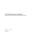
1-1-2 Parts names
!
(1) Printer
@
1
0
9
#$ % ^
8
2
7
‹
¤
&
3
6
4
5
⁄
)
(
·
—
›
*
fi
fl
‡
Figure 1-1-1
1 Operator panel
2 Front cover
3 Lower paper cassette
4 Paper guide
5 Paper stopper
6 Upper paper cassette
7 Handles for transport
8 MP (Multi-Purpose) tray
9 Power switch
0 Face-down tray
! Toner container
@ Toner container release lever
# Waste toner box
$ Cleaning knob
% Main charger unit
^ Cleaning brush
& Power cord
* Power cord connector
( Option unit connector
) Handles for transport
⁄ Side cover
¤ Conveying cover lock lever
‹ Conveying cover
› Parallel cable connector
fi Network cable connector
fl Serial cable connector
‡ Optional hard disk unit slot (OPT1/HDD)
— Optional network interface card slot (OPT2)
· Memory card slot
1-1-3
FS-9100DN/9500DN
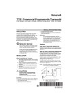
(2) Operator panel
0
6 ! 7 @ 8 9
READY
DATA
#
ATTENTION
Ready
- - - A4 PLAIN
INTERFACE
SIZE
TYPE
GO
MENU
ENTER
CANCEL
4
Figure 1-1-2
1 GO key
2 CANCEL key
3 ENTER key
4 MENU key
5 Arrow keys
6 Ready indicator
7 Data indicator
8 Attention indicator
9 Message display
0 Interface indicator
! Paper size indicator
@ Paper type indicator
# Paper jam indicator
1-1-4
3
2
1
5
FS-9100DN/9500DN
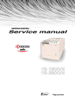
1-1-3 Machine cross section
Light path
Paper path
Figure 1-1-3 Machine cross section
1
2
3
4
5
6
7
8
9
Paper feed section
Main charging section
Laser scanner unit
Developing section
Transfer and paper conveying section
Cleaning and erasing section
Fuser section
Eject and switchback section
Duplex unit
1-1-5
FS-9100DN/9500DN
1-1-4 Drive system
(1) Drive system 1 (drive motor and eject motor drive trains)
As viewed from machine rear
Figure 1-1-4
1
2
3
4
5
6
7
8
1-1-6
Drive motor gear
Drum gear Z76H/Z30H
Drum gear Z70H
Gear Z76H/Z35H
Gear Z50H
Gear Z36S/Z31H
Gear Z37H/28H
Gear Z34H
9
0
!
@
#
$
%
^
Registration clutch gear
Gear Z63H/Z45S
Gear Z37S
Gear Z24S
Joint gear Z32S
Eject motor gear
Gear Z47S/Z28S
Eject gear Z30S
FS-9100DN/9500DN
(2) Drive system 2 (paper feed motor drive train)
As viewed from machine rear
Figure 1-1-5
1
2
3
4
5
6
7
8
9
0
Paper feed motor gear
Gear Z76H/Z35S
Feed gear Z25
Feed gear Z25
Feed gear Z25
Feed gear Z25
Gear Z41S/Z24S/P30
Upper paper feed clutch gear
Paper feed drive belt
Gear Z41S/Z24S/P30
!
@
#
$
%
^
&
*
(
)
Lower paper feed clutch gear
Gear Z41S/P15
Bypass drive belt
Gear Z60S/P20
Gear Z41S/P18
Gear Z40S/Z32S
Container drive belt
Gear Z24S/P40
Gear Z40S/Z25S
Container gear
1-1-7
CONTENTS
1-2 Handling precautions
1-2-1 Drum ......................................................................................................................................................... 1-2-1
1-2-2 Toner ........................................................................................................................................................ 1-2-1
1-2-3 Installation environment ........................................................................................................................... 1-2-1
FS-9100DN/9500DN
1-2-1 Drum
Note the following when handling or storing the drum.
• When removing the image formation unit, never expose the drum surface to strong direct light.
• Keep the drum at an ambient temperature between –20 °C/–4 °F and 40 °C/104 °F and at a relative humidity not higher
than 85% RH. Avoid abrupt changes in temperature and humidity.
• Avoid exposure to any substance which is harmful to or may affect the quality of the drum.
• Do not touch the drum surface with any object. Should it be touched by hands or stained with oil, clean it.
1-2-2 Toner
Store the toner in a cool, dark place. Avoid direct light and high humidity.
1-2-3 Installation environment
1. Temperature: 10 - 32.5 °C/50 - 90.5 °F
2. Humidity: 20 - 80 % RH
3. Power supply: 120 V AC ±10 %, 10.8 A/10.9 A (FS-9100DN/9500DN)
220 - 240 V AC 10 %, 5.6 A/5.7 A (FS-9100DN/9500DN)
4. Power source frequency: 50 Hz ±0.2 %/60 Hz ±0.2 %
5. Installation location
• Avoid direct sunlight or bright lighting. Ensure that the photoconductor will not be exposed to direct sunlight or other
strong light when removing paper jams.
• Avoid extremes of temperature and humidity, abrupt ambient temperature changes, and hot or cold air directed onto
the machine.
• Avoid dust and vibration.
• Choose a surface capable of supporting the weight of the machine.
• Place the machine on a level surface (maximum allowance inclination: 1 ° ).
• Avoid air-borne substances that may adversely affect the machine or degrade the photoconductor, such as
mercury, acidic of alkaline vapors, inorganic gasses, NOx, SOx gases and chlorine-based organic solvents.
• Select a room with good ventilation.
6. Allow sufficient access for proper operation and maintenance of the machine.
Machine front: 100 cm/393/8" Machine rear: 10 cm/315/16"
Machine left: 60 cm/235/8"
Machine right: 70 cm/279/16"
d
f
a
c
b
e
a: 585 mm/231/16"
b: 615 mm/243/16"
c: 665 mm/263/16"
d: 1032 mm/405/8"
e: 920 mm/361/4"
f: 1055 mm/419/16"
Figure 1-2-1 Installation dimensions
1-2-1
CONTENTS
1-3 Installation
1-3-1 Unpacking and installation ....................................................................................................................... 1-3-1
(1) Installation procedure ........................................................................................................................ 1-3-1
1-3-2 Installing the cassette heater (option) ...................................................................................................... 1-3-9
1-3-3 Installing DIMMs (option) ......................................................................................................................... 1-3-11
1-3-4 Installing the network interface card (option) .......................................................................................... 1-3-12
1-3-5 Installing the hard disk (option) .............................................................................................................. 1-3-13
1-3-6 Installing the memory card (option) ........................................................................................................ 1-3-14
FS-9100DN/9500DN
1-3-1 Unpacking and installation
(1) Installation procedure
Start
Unpacking.
Removing the tapes.
Placing the proper location.
Installing the toner container.
Installing the waste toner box.
Connecting the printer to the computer.
Connecting the power cord.
Printing a status page for test.
Completion of the machine installation.
1-3-1
FS-9100DN/9500DN
Unpacking.
Figure 1-3-1 Unpacking
Paper size plate (4)
Printer
CD-ROM
Toner container
Installation guide
Quick configuration guide
(for network interface)
Waste toner box
Power cord
(220-240 V models only)
Figure 1-3-2 List of shipped components
1-3-2
FS-9100DN/9500DN
Removing the tapes.
1. Remove the tape holding the front cover.
2. Remove the tape holding the MP tray.
3. Remove the two tapes holding the paper
cassettes.
Tape
Tape
Tapes
Figure 1-3-3
Tape
4. Remove the tapes holding the conveying cover.
Figure 1-3-4
5. Pull out the upper paper cassette and remove the
two tapes holding the bottom plate.
6. Pull out the lower paper cassette and remove the
two tapes holding the bottom plate.
Tape
Figure 1-3-5
1-3-3
FS-9100DN/9500DN
Placing the proper location.
1. Place the printer in a proper location.
Rear: 10 cm (315/16")
Right:
70 cm (279/16")
Left:
60 cm (235/8")
Front: 100 cm (393/8")
Figure 1-3-6
Installing the toner container.
1. Open the printer front cover all the way.
Front cover
Figure 1-3-7
2. Take out the toner container from the bag.
3. Tap the new toner container on the top 5 to 6
times.
Toner container
Figure 1-3-8
1-3-4
FS-9100DN/9500DN
4. Thoroughly shake the toner container (in the
directions of the arrows) ten times or more to
loosen and mix the toner inside.
Toner container
Figure 1-3-9
5. Grasp the handle on the toner container and
insert the toner container along the rail of the
printer.
Toner container
Figure 1-3-10
6. Hold the toner container by hands and fully insert
it into the printer.
Figure 1-3-11
1-3-5
FS-9100DN/9500DN
Installing the waste toner box.
1. Install the waste toner box as shown in the figure.
2. Close the front cover.
Waste toner box
Figure 1-3-12
Connecting the printer to the computer.
There are various ways of connecting the printer to the computer, such as through the parallel interface connecter, serial
interface connecter, or through the network interface connecter.
Printer (Right side)
Parallel interface
Serial interface
Power cord
Figure 1-3-13
1-3-6
Network
FS-9100DN/9500DN
• Parallel interface connection
1. Plug one end of the printer cable (not included)
into the parallel interface connection on the right
side of the printer.
2. Close the clips on both sides to fix the connector
in place.
Plug the other end of the printer cable Into the
computer‘s parallel Interface connection.
Parallel printer cable
Figure 1-3-14
• Serial interface connection
1. Plug one end of the printer cable (not Included)
Into the serial Interface connection on the right
side of the printer.
2. Securely tighten the screws on both sides of the
connecter.
Plug the other end of the printer cable Into the
computer‘s serial Interface connection.
Serial printer cable
Figure 1-3-15
• Network interface connection
Network cable
1. Plug the network cable (not included) into the
network interface connection on the right side of
printer.
Figure 1-3-16
1-3-7
FS-9100DN/9500DN
Connecting the power cord.
1. Plug the power cord into the power cord
connector on the rear of the printer. (220 - 240 V
models only)
2. Connect the other end of the power cord into a
power outlet.
Power cord connector
(220 - 240 V models only)
Power cord
Figure 1-3-17
Printing a status page for test.
1. Add paper in the paper cassette.
2. Turn on the printer power switch.
"Adding toner" will be displayed and the toner
supply action will be taken for about 8 minutes.
3. Press the MENU key on the operation panel.
4. Press the or key repeatedly until [Print
Status page] is displayed.
5. Press the ENTER key twice. A status page is
printed.
Completion of the machine installation.
1-3-8
FS-9100DN/9500DN
1-3-2 Installing the cassette heater (option)
Cassette heater installation requires the following parts:
• Cassette heater (P/N 34860030): for 120 V specifications
• Cassette heater (P/N 33960020): for 220 - 240 V specifications
• Binding band (P/N M2107120)
• Two binding screws BVM4X6 (P/N B1304060)
• Caution label (P/N 20305130)
• Fax kit label (P/N 3CM05010)
Screws
Procedure
1. Pull the upper and lower cassettes out.
2. Install the cassette heater to the bottom of the
machine with two screws (M4X06), and bind
the wire of the cassette heater with the band.
3. Put the wire of the cassette heater out of the
machine through the aperture of the rear
frame.
4. Stick the caution label in front of the cassette
heater.
Aperture
Caution label
Band
Cassette heater
Figure 1-3-18
5. Remove the five screws and the two
connectors and then remove the power
supply mount from the rear side of the
machine.
Pay attention not to reverse the black wire
and white wire when refitting the connector.
Connectors
Power supply mount
6. Remove the two screws and pull out the wire
of the cassette heater that has been put out
of the rear frame while raising the power
supply unit.
7. Insert the connector of the cassette heater
into the connector of the machine.
8. Fold the wire of the cassette heater and insert
it into the clamp of the power supply mount
as shown in the figure.
Figure 1-3-19
Power supply
mount
Power supply unit
Clump
Connector
Wire of the cassette heater
Wire of the
cassette heater
Figure 1-3-20
1-3-9
FS-9100DN/9500DN
9. Stick the label below the power switch.
10. Refit all the removed parts.
Label
Figure 1-3-21
1-3-10
FS-9100DN/9500DN
1-3-3 Installing DIMMs (option)
Procedure
• Installing DIMM
1. Remove two screws and then remove the
main controller PWB (see page 1-6-24).
2. Open the clips on both ends of the DIMM
socket.
3. Insert the DIMM into the socket, so that the
notches on the DIMM align with the
corresponding protrusions in the socket.
DIMM
Figure 1-3-22
4. Close the clips of the DIMM socket to secure
the DIMM.
5. When you finish installing the DIMM, reinsert
the main controller PWB into the printer.
Clip
Clip
Figure 1-3-23
• Removing DIMM
1. To remove a DIMM, carefully pull the end
clips outwards, then pull the DIMM out of the
socket.
Clip
Clip
Figure 1-3-24
1-3-11
FS-9100DN/9500DN
1-3-4 Installing the network interface card (option)
Procedure
1. Remove the two screws from the option
interface slot cover.
Option interface
slot cover
Figure 1-3-25
2. Insert the network interface card and secure it
with the screws removed in step 1.
Network interface card
Figure 1-3-26
3. Connect the network cable.
Network cable
Figure 1-3-27
1-3-12
FS-9100DN/9500DN
1-3-5 Installing the hard disk (option)
Procedure
1. Remove two screws and remove the slot
cover.
Slot cover
Figure 1-3-28
2. Insert the optional hard disk unit into the slot.
Hard disk unit
Figure 1-3-29
3. Tighten the two screws to secure the hard
disk unit to the main controller PWB.
Hard disk unit
Figure 1-3-30
1-3-13
FS-9100DN/9500DN
1-3-6 Installing the memory card (option)
Procedure
1. Turn off the printer.
Note: Do not insert or remove a memory card
(CompactFlash) while power in on. If the
memory card is removed while the
printer is on, damage could result in the
printer's electronics or the memory card.
2. Insert the memory card in the slot. Insert it as
its label surface facing toward outside,
connector end first. Push it in all the way.
Memory card
Figure 1-3-31
1-3-14
CONTENTS
1-4 Service and maintenance mode
1-4-1 Service mode ........................................................................................................................................... 1-4-1
(1) Executing service mode .................................................................................................................... 1-4-1
1-4-2 Maintenance mode ................................................................................................................................... 1-4-7
(1) Maintenance mode ........................................................................................................................... 1-4-7
(2) Executing a maintenance item .......................................................................................................... 1-4-8
(3) Contents of maintenance mode items ............................................................................................ 1-4-10
1-4-3 Maintenance ........................................................................................................................................... 1-4-27
(1) Replacing the toner container ......................................................................................................... 1-4-27
FS-9100DN/9500DN
1-4-1 Service mode
The printer is equipped with the service mode that can be accessed in the manu system. The service mode is intended
for use by the service person for maintenance and service for the items explained in the following sections.
(1) Executing service mode
Message display
Ready
––– A4 PLAIN
1 Press the MENU key.
Print
Menu Map
2 Press the or key several times
until [Others >] is displayed.
Others
>
>MSG Language
English
3 Press the ENTER key.
4 Press the or key several times
until [>Service >] is displayed.
>Service
>
5 Press the
key.
Service mode items
>>Print
Status Page
To print a status page for service purpose.
See page 1-4-2.
>>Developer
To initial setting for the developer.
See page 1-4-3.
>>Drum
To performing a drum refreshing.
See page 1-4-3.
1-4-1
FS-9100DN/9500DN
Service items
>>Print
Status Page
Description
Printing a status page for service purpose
Description
Service information on the status page include various settings for the printer, service
statistics, etc.
Purpose
To understand the machine environments and general settings.
Method
1. Enter the service mode [>>Printing Status Page].
2. Press the Enter key. "?" will be displayed.
3. Press the Enter key. The status page is printed. (See the figure below)
Controller firmware version
Released date of the firmware
Firmware version:
Released:
Jun/30/2001
Service information
[0104/A003] [C1] [22.00AFUB] [03/03]
Total page 9690
/t/P00/S00/F00/N00/D10:DM0301.DAN
/0020/0020/1061/0811/ 0/ 0/ 0/ 0/ 0/ 0/ 0/ 0/ 0/ 0/ 0/
/AAADCFE/AAADCFE/AAADCFE/AAADCFE/AAADCFE/AAADCFE/AAADCFE/AAADCFE/AAADCFE/
/AAADCFE/AAADCFE/AAADCFE/AAADCFE/AAADCFE/AAADCFE/AAADCFE/AAADCFE/AAADCFE/AAADCFE/
/AAADCFE/
/AAADCFE/AAADCFE/AAADCFE/AA/DC/
/AAADCFE/AAADCFE/AAADCFE/AAADCFE/AAADCFE/AAADCFE/AAADCFE/AAADCFE/AAADCFE/
/AAADCFE/AAADCFE/AAADCFE/AAADCFE/AAADCFE/
/AAADCFE/AAADCFE/AAADCFE/AAADCFE/AAADCFE/AAADCFE/AAADCFE/AAADCFE/AAADCFE/
/0000/
/RS2/FF/00/AI.E/81/31/50
/808880888080808000/808880888080808000/808880888080808000/808880888080808000/
/808880888080808000/808880888080808000/808880888080808000/808880888080808000/
/808880888080808000/808880888080808000/808880888080808000/808880888080808000/
/808880888080808000/808880888080808000/808880888080808000/808880888080808000/
/808880888080808000/808880888080808000/808880888080808000/808880888080808000/
/20A11080/1020B200/20001080/81000000/00000000/10101010/10101010/
SPD1:0203040508090A0B0C0D0F101112131415161718191A1B1C1D1E1F202122235E
SPD2:0203040508090A0B0C0D0F101112131415161718191A1B1C1D1E1F202122235E
DN:SPL9200007 SN:SPL9200010
Service information (See the next page.)
Figure 1-4-1
1-4-2
FS-9100DN/9500DN
Service items
Description
Detail of service information
Service information
[0104/A103] [C1] [22.00AFUB] [03/03]
Total page 9690
1
2
3
4
5
/t/P00/S00/F00/N00/D10:DM0301.DAN
6 7 8 9 0
!
/0020/0020/1061/0811/ 0/ 0/ 0/ 0/ 0/ 0/ 0/ 0/ 0/ 0/ 0/
#
$
@
/AAADCFE/AAADCFE/AAADCFE/AAADCFE/AAADCFE/AAADCFE/AAADCFE/AAADCFE/AAADCFE/
%
/AAADCFE/AAADCFE/AAADCFE/AAADCFE/AAADCFE/AAADCFE/AAADCFE/AAADCFE/AAADCFE/AAADCFE/
^
/AAADCFE/
&
/AAADCFE/AAADCFE/AAADCFE/AA/DC/
*
( )
/AAADCFE/AAADCFE/AAADCFE/AAADCFE/AAADCFE/AAADCFE/AAADCFE/AAADCFE/AAADCFE/
⁄
/AAADCFE/AAADCFE/AAADCFE/AAADCFE/AAADCFE/
¤
/AAADCFE/AAADCFE/AAADCFE/AAADCFE/AAADCFE/AAADCFE/AAADCFE/AAADCFE/AAADCFE/AAADCFE/
‹
/0000/
›
/RS2/FF/00/AI.E/81/31/50
fi fl ‡ ° · ‚ Œ
/8088808880808000/8088808880808000/8088808880808000/8088808880808000/
„ (1)
/8088808880808000/8088808880808000/8088808880808000/8088808880808000/
„ (2)
/8088808880808000/8088808880808000/8088808880808000/8088808880808000/
„ (3)
/8088808880808000/8088808880808000/8088808880808000/8088808880808000/
„ (4)
/8088808880808000/8088808880808000/8088808880808000/8088808880808000/
´
/20A11080/1020B200/20001080/81000000/00000000/10101010/10101010/
‰
SPD1:0203040508090A0B0C0D0F101112131415161718191A1B1C1D1E1F202122235E
ˇ
SPD2:0203040508090A0B0C0D0F101112131415161718191A1B1C1D1E1F202122235E
Á
DN:SPL9200007 SN:SPL9200010
ˆ
¨
Item
Description
1 Engine controller PWB flash ROM information
2 Operator panel PWB mask ROM information
[ROM version]
[ROM version]
3 Boot ROM and flash DIMM type information
First 6 digits: boot ROM version
Last 3 digits: flash DIMM type
MXI: Macronix / SHB: SHARP (LH28F160B)
FUB: Fujitsu (bottom type) / FUT: Fujitsu (top type)
HUB: HYUNDAI (bottom type) / HUT: (top type)
- - -: Other type flash DIMM / ***: Mask DIMM
1-4-3
FS-9100DN/9500DN
Service items
Description
Item
4 Software jumper switch information
(Hexadecimal)
Description
First byte
Bit 7: always 0 (MSB)
Bit 6: 0 Non MICR mode
Bit 5: 0: For Europe
1: For U.S.
Bit 4: 0: Kyocera
1: OEM
Bit 3: always 0
Bit 2: always 0
Bit 1: 0: Overseas
1: Domestic (Japan)
Bit 0: always 0 (LSB)
Second byte
OEM information: Displayed in OEM mode only.
5 Total page counter
6 Toner install information
7 Parallel I/O information
8 Serial I/O error code
00: Normal
Bit 2: 1: Parity error
Bit 1: 1: Overrun error
Bit 0: 1: Framing error
9 Operation panel key lock status
(Displayed only when locked)
01: Partial lock
02: Full lock
0 NVRAM error code
(Displays only when error occurred)
01: ID error
02: Version error
03: Checksum error
04: NVRAM crush error
! NVRAM downloading status
00: Normal downloaded
Bit 7: Error occurred (MSB)
Bit 6: Reserved
Bit 5: OEM data
Bit 4: Operator panel message data (File name displayed)
Bit 3: Program data
Bit 2: Macro data
Bit 1: Host data
Bit 0: Font data (LSB)
@ Printable area information
Top offset / Left offset / Page length / Page width
# Left offset
MP tray / Cassette 1 / Cassette 2 / Cassette 3 / Cassette 4 /
Duplex unit
$ Top offset
MP tray / Cassette 2 / Cassette 3 / Cassette 4 / Duplex unit
% Life counter of paper feed position
(Main body of printer)
Cassette 1 (total) / Cassette 1 (small) / Cassette 1 (large)
Cassette 2 (total) / Cassette 2 (small) / Cassette 2 (large)
MP tray (total) / MP tray (small) / MP tray (large)
*"Small" means sizes A4/letter or smaller
*Total = large x 2 + small
^ Life counter of paper feed position
(Option paper feeder, duplex unit)
PF-70 cassette 1 (total) / PF-70 cassette 1 (small) /
PF-70 cassette 1 (large)
PF-70 cassette 2 (total) / PF-70 cassette 2 (small) /
PF-70 cassette 2 (large)
PF-75 (total)
Duplex unit (total) / Duplex unit (small) / Duplex unit (large)
*"Small" means sizes A4/letter or smaller
*Total is calculated with the expression large x 2 + small.
& Life counter of paper eject position
Face-down
* Life counter of each unit
Drum / Developer / Fuser
( Toner low FPR display threshold
) MP kit replacement threshold
1-4-4
FS-9100DN/9500DN
Service items
Description
Item
⁄ Life counter of document finisher DF-70
¤ Life counter of book-let finisher DF-75 (1)
Description
Total pages / Tray 1 page / Tray 2 page
Staple (total) / Staple (front) / Staple (rear) / Staple (upper
left) / Staple (lower left) / Staple (two positions)
*Total pages = Tray 1 page + Tray 2 page
*Staple (total) = Staple (upper left) +
Staple (lower left) + Staple (two positions)
*Staple (front) = Staple (upper left) + Staple (two positions)
*Staple (rear) = Staple (upper left) + Staple (two positions)
Total / Face-down tray / Book-let tray total /
Book-let tray (small) / Book-let tray (large)
*"Small" means sizes A4/letter or smaller
*Total = face-down tray + book-let tray total
‹ Life counter of book-let finisher DF-75 (2)
Total / front / rear / upper left / lower left / two positions
(page end) / two positions (book-let) total / two positions
(book-let) 2 - 3 sheets / two positions (book-let) 4 - 6 sheets
/ two positions (book-let) 7 - 10 sheets
*Front = Upper left + two positions (page end) +
two positions (book-let) total
*Rear = Lower left + two positions (page end) +
two positions (book-let) total
*Total = Upper left + lower left + two positions (page end) +
two positions (book-let) total
› EEPROM error of each unit
Bit 7: EEPROM error of Drum (MSB)
Bit 6: EEPROM error of large capacity stacker
Bit 5 - 1: Reserved
Bit 0: EEPROM error of first cassette of optional paper
feeder PF-70 (LSB)
fi Serial interface information
RS2: RS-232C
fl Drum sensitivity information
‡ Calibration table setting
Preset value of FRPO 14 (Hexadecimal)
— Average print density (%)
2 digits of integer part and 1 digit of fraction part (total print
density from shipping from factory)
· Operation panel message language
‚ Current temperature
ΠCurrent humidity
0 to 80 °C ("–" = Humidity/temperature sensor is abnormal.)
5 to 100 %RH (in 1% increment)
„ Various correction values for maintenance mode
´ Engine parameter setting
‰ Media type attributes
Media type 1 to 28 (14 to 20: Reserved)
ˇ SPD information (slot 1)
Á SPD information (slot 2)
¨ Drum serial number
ˆ Printer serial number
1-4-5
FS-9100DN/9500DN
Service items
>>Developer
Description
Initializing the developer unit
Description
Feeds toner from the toner container to the developer unit.
Purpose
To execute when the developer unit has been replaced.
Method
1. Enter the service mode [>>Developer].
2. Press the Enter key. "?" will be displayed.
3. Press the Enter key.
4. Turn off and on the printer.
Toner is fed from the toner container to the developer unit.
Drum surface refreshing
>>Drum
Description
The drum rotates for approximately 5 minutes without printing operation.
Purpose
To clean the drum surface when an image problem occurs.
Method
1. Enter the service mode [>>Drum].
2. Press the Enter key. "?" will be displayed.
3. Press the Enter key. Drum surface refreshing will start.
1-4-6
FS-9100DN/9500DN
1-4-2 Maintenance mode
(1) Maintenance mode
The printer is equipped with a maintenance function which can be used to maintain and service the machine.
To run the maintenance mode, Insert a compact flash card to which the API program has been written into the printer
and load the API program to the printer using either method.
* Turn off and on the printer. The API program will be automatically loaded into the printer.
* Load the API program with read program.
* Enter the MENU mode and display the [>>Read Program Maintenance API] in the [Memory Card>], then press the ENTER
key.
The maintenance mode can be executed from the MENU mode.
If the compact flash card is removed from the printer and then the printer is turned off and on, the API program will be
deleted from the printer and the maintenance mode will be deleted from the MENU mode.
1-4-7
FS-9100DN/9500DN
(2) Executing a maintenance item
Message display
Ready
––– A4 PLAIN
1 Press the MENU key.
Print
Menu Map
2 Press the or key several times
until [Maintenance >] is displayed.
Maintenance
>
Mode
[##]
Maintenance
>
Mode
[##] ?
3 Press the ENTER key.
3 Press the
[##] indicates the version of
the maintenance mode.
key.
4 Press the ENTER key.
>Default Data
[U002] Set
Initializing data for engine controller
See page 1-4-10.
>Print Without
[U005] Paper ###
Printing without paper
See page 1-4-10.
>Drive Motor
[U030]
Checking motor operation
See page 1-4-10.
>
>Check Switches>
[U031]
Checking switches for paper conveying
See page 1-4-11.
>Check Cluches >
[U032]
Checking clutch operation
See page 1-4-11.
>Set Folio Size
[U035] ######
Setting folio size
See page 1-4-12.
>Check Cover SW>
[U038]&InterLock
Checking the printer cover switch
See page 1-4-12.
>Set of Paper >
[U051] Loop
Setting the amount of slack in the paper
See page 1-4-13.
>Adjust Motor >
[U053] Speed
Performing fine adjustment of
the motor speed
See page 1-4-14.
>Adjust High >
[U101] Voltage
Setting control voltages
See page 1-4-15.
>Adjust Toner >
[U112] Refresh
Setting toner refresh operation
See page 1-4-16.
>Toner MT Move
[U135]
Checking the toner motor operation
See page 1-4-16.
Continued to the next page
1-4-8
The test page is printed.
FS-9100DN/9500DN
>Ignore Toner
[U136] Empty ###
Switching empty toner status detection
See page 1-4-16.
>Set Toner Mode
[U144] ######
Setting toner loading operation
See page 1-4-17.
>Check Sensor >
[U150]
Checking sensors
See page 1-4-17.
>Adjust Fixing>
[U161] Heater
Setting the fixing control temperature
See page 1-4-18.
>Turn Fixing >
[U196]Heater ON
Turning the fixing heater on
See page 1-4-19.
>Display TEMP >
[U199]
Checking the fixing temperature
See page 1-4-19.
>Set Bulk Feeder
[U208] Size ##
Setting the paper size for the paper
feeder PF-75
See page 1-4-20.
>Adjust Finish.>
[U237]Limit ####
Setting finisher stack quantity
See page 1-4-20.
>Set LSU Type
[U274]
#
Setting LSU type
See page 1-4-21.
>Print Menu
[U392]
>
>Initialize
[U393] Menu
>
Outputs of the history of events of
the service calls and paper jam
See page 1-4-21.
Initializing data for FRPO
See page 1-4-22.
>Set Paper Feed>
[U394] Top Reg.
Adjusting leading edge margin for
each paper cassette
See page 1-4-22.
>Check MP tray
[U395] Size ###
Checking size in MP tray
See page 1-4-23.
>Check cassett>
[U396] Remain
Displaying the amount of paper
remaining in each paper cassette
See page 1-4-23.
>Set Paper Feed>
[U398] Regist
Adjusting left margin for each paper
cassette
See page 1-4-24.
>Set FRPO
>
[U395] Parameter
Checking size in MP tray
See page 1-4-24.
>Adjust Margin>
[U402]
Adjusting margins of image printing
See page 1-4-25.
>Aging Mode
[U950]
Executing aging mode
See page 1-4-25.
>
>Option Check >
[U951]
Checking connection status of each
optional equipment
See page 1-4-26.
1-4-9
FS-9100DN/9500DN
(3) Contents of maintenance mode items
Maintenance
item No.
U002 Initializing data for engine controller
Description
Description
Initializing the backup RAM for engine controller to return to the original settings.
Purpose
Used to return the machine settings to initial settings.
Method
1. Enter the maintenance mode and press the
2. Press the ENTER key. "?" will be displayed.
or
key to display "U002".
>Default Data
[U002] Set?
3. Press the ENTER key. Each setting will be initialized.
To keep the setting, press the CANCEL key.
U005
Printing without paper
Description
Switches to the machine operation control without paper
Purpose
To check the overall operation of the machine.
Method
1. Enter the maintenance mode and press the or key to display "U005".
2. Press the ENTER key. "?" will be displayed.
3. Press the or key to turn on or off printing without paper.
>Print Without
[U005] Paper?Off
4. Press the ENTER key. The setting is set.
To keep the setting, press the CANCEL key.
U030
Checking motor operation
Description
Drives each motor.
Purpose
To check the operation of each motor.
Method
1. Enter the maintenance mode and press the
or
key to display "U030".
>Drive Motors >
[U030]
2. Press the
3. Press the
key to display the submenu screen.
or key to select the motor to activate.
Display
Operation
FEED Motor
MAIN Motor
EJECT MT (FW)
EJECT MT (REV)
Paper feed motor operates
Drive motor operates
Eject motor rotates forward
Eject motor rotates in reverse
4. Press the ENTER key. "Execute" will be displayed and operation will start.
>>FEED Motor
[030.1] Execute
5. To stop operation, press the ENTER key or the CANCEL key.
1-4-10
FS-9100DN/9500DN
Maintenance
item No.
U031 Checking switches for paper conveying
Description
Description
Displays the on-off status of each paper detection switch on the paper path.
Purpose
To check if the switches for paper conveying operate correctly.
Method
1. Enter the maintenance mode and press the
or
key to display "U031".
>Check Switches>
[U031]
2. Press the
3. Press the
key to display the submenu screen.
or key to select the switch to check.
Display
Switches
Check SW F1
Check SW F2
Check SW F3
Check SW MP
Check SW RES
Check SW EJE
Check SW BRA
Check SW DUP
Feed switch 1 (FSW1)
Feed switch 2 (FSW2)
Feed switch 3 (FSW3)
MP feed switch (MPFSW)
Registration switch (RSW)
Eject switch (ESW)
Feedshift switch (FSSW)
Duplex paper conveying switch (DUPPCSW)
4. Turn on or off the switch manually to check the switch status. 0: Off 1: On
>>Check SW F1:0
[031.1] SW F2:0
U032
Checking clutch operation
Description
Turns each clutch on.
Purpose
To check the operation of each clutch.
Method
1. Enter the maintenance mode and press the
or
key to display "U032".
>Check Clutches>
[U032]
2. Press the
3. Press the
key to display the submenu screen.
or key to select the clutch to operate.
Display
Clutches
PF1 Clutch
PF2 Clutch
PFMP Clutch
FEED1 Clutch
FEED2 Clutch
FEED3 Clutch
MPTF Clutch
RES Clutch
DUPF Clutch
Upper paper feed clutch (PFCL-U)
Lower paper feed clutch (PFCL-U)
MP paper feed clutch (MPPFCL)
Feed clutch 1 (FCL1)
Feed clutch 2 (FCL2)
Feed clutch 3 (FCL3)
MP feed clutch (MPFCL)
Registration clutch (RCL)
Duplex feed clutch (DUPFCL)
4. Press the ENTER key. "Execute" will be displayed and operation will start.
>>PF1 Clutch
[032.1] Execute
5. To stop operation, press the ENTER key or the CANCEL key.
1-4-11
FS-9100DN/9500DN
Maintenance
item No.
U035 Setting folio size
Description
Description
Sets the type of paper when using Folio or Oficioll.
Purpose
To prevent image loss that occurs depending on the difference of paper type.
Method
1. Enter the maintenance mode and press the or
2. Press the ENTER key. "?" will be displayed.
3. Press the or key to select folio or oficioll.
key to display "U035".
>Set Folio Size
[U035]?Folio
4. Press the ENTER key. The setting is set.
To keep the setting, press the CANCEL key.
U038
Checking the printer cover switch
Description
Displays the on-off status of each cover switch.
Purpose
To check if the switches of covers operate correctly.
Method
1. Enter the maintenance mode and press the
or
key to display "U038".
>Check Cover SW>
[U038]&InterLock
2. Press the
3. Press the
key to display the submenu screen.
or key to select the switch to check.
Display
Switches
Left cover 1
Left cover 2
Front cover
Int. Lck
Conveying cover switch (CCSW)
Side cover switch (SCSW)
Front cover switch (FRCSW)
Safety switch 1 and 2 (SSW1 and 2)
3. Open and close the cover to check the switch status. 0: Off 1: On
>>Left Cover 1:1
[038.1]
2:1
1-4-12
FS-9100DN/9500DN
Maintenance
item No.
U051 Setting the amount of slack in the paper
Description
Description
Changes the preset value of the amount of slack of resist or feed.
Purpose
To adjust when the leading edge of the image is not printed or fluctuates irregularly or paper is bent in Z shape.
Method
1. Enter the maintenance mode and press the
or
key to display "U051".
>Set of Paper >
[U051] Loop
2. Press the
3. Press the
key to display the submenu screen.
or key to select the item for which the preset value is to be changed.
Display
Description
Setting range
Initial setting
RES FEEDER
Amount of slack of resist in feeding from
the paper cassette in the printer
Amount of slack of resist in feeding from
the MP tray
Amount of slack of resist in feeding for
duplex printing
Amount of slack of feed in feeding from
the MP tray
Amount of slack of feed in feeding from
the upper cassette in the printer
Amount of slack of feed in feeding from
the lower cassette in the printer
Amount of slack of feed in feeding from
the upper cassette in PF-70
Amount of slack of feed in feeding from
the lower cassette in PF-70
Amount of slack of feed in feeding from
PF-75
-30 to +20
0
-30 to +20
0
-30 to +20
-3
-30 to +20
0
-30 to +20
0
-30 to +20
0
-30 to +20
0
-30 to +20
0
-30 to +20
0
RES MPT
RES DUP
FEED MPT
FEED CASS1
FEED CASS2
FEED CASS3
FEED CASS4
FEED 3000F
4. Press the ENTER key. "_" will blink.
>>RES FEEDER
[051.1]
##
5. Press the or key to move "_" to the digit position at which the value is to be changed and press the
key to change the preset value.
6. Press the ENTER key. The value is set.
To keep the preset value, press the CANCEL key.
or
1-4-13
FS-9100DN/9500DN
Maintenance
Description
item No.
U053 Performing fine adjustment of the motor speed
Description
Performs fine adjustment of the speeds of the motors.
Purpose
Used to adjust the speed of the respective motors when the magnification is not correct.
Method
1. Enter the maintenance mode and press the
or
key to display "U053".
>Adjust Motor >
[U053] Speed
2. Press the
3. Press the
key to display the submenu screen.
or key to select an item for which the preset value is to be changed.
Display
Description
Setting range
Initial setting
Main Motor
Eject Motor
Polygon Motor
Drive motor speed adjustment
Eject motor speed adjustment
Polygon motor speed adjustment
0 to +14
-20 to +20
-20 to +20
10
7
2
4. Press the ENTER key. "_" will blink.
>>Main Motor
[053.1]
##
5. Press the or key to move "_" to the digit position at which the value is to be changed and press the or
key to change the preset value.
MAIN MOTOR
Increasing the setting makes the image longer in the auxiliary scanning direction, and decreasing it makes
the image shorter in the auxiliary scanning direction.
POLYGON MOTOR
Increasing the setting makes the image longer in the main scanning direction and shorter in the auxiliary
scanning direction; decreasing the setting makes the image shorter in the main scanning direction and
longer in the auxiliary scanning direction.
EJECT MOTOR
Normally no change is necessary but this can be used as countermeasures against wrinkles (waving) of
paper.
6. Press the ENTER key. The value is set.
To keep the preset value, press the CANCEL key.
1-4-14
FS-9100DN/9500DN
Maintenance
item No.
U101 Setting control voltages
Description
Description
Changes the developing bias voltage and transfer voltage by changing the developing bias control voltage and
transfer control voltage.
Purpose
To check or change the developing bias and transfer voltage.
Method
1. Enter the maintenance mode and press the
or
key to display "U101".
>Adjust High >
[U101] Voltage
2. Press the
3. Press the
key to display the submenu screen.
or key to select an item for which the preset value is to be changed.
Display
Description
Setting range
Initial setting
DEV BIAS
Developing bias AC component
frequency at image formation
Developing bias AC component duty
at image formation
Developing bias shift amount
Transfer control voltage
-255 to 255 (KHz)
0
-100 to +100 (%)
0
-1 to +1
0 to 255 (uA)
0
0
DEV DUTY
DEV SBIAS
TC DATA
Increasing the DEV BIAS setting makes the image darker; decreasing it makes the image lighter.
Increasing the DEV DUTY setting makes the image lighter; decreasing it makes the image darker.
Increasing the DEV SBIAS setting makes the image darker; decreasing it makes the image lighter.
Increasing the TC DATA setting makes the transfer voltage higher, and decreasing it makes the voltage
lower.
4. Press the ENTER key. "_" will blink.
>>DEV BIAS
[101.1] ### KHz
5. Press the or key to move "_" to the digit position at which the value is to be changed and press the
key to change the preset value.
6. Press the ENTER key. The value is set.
To keep the preset value, press the CANCEL key.
or
1-4-15
FS-9100DN/9500DN
Maintenance
item No.
U112 Setting toner refresh operation
Description
Description
Sets the toner refresh operation time and the developing bias on time at power on and after printing.
Purpose
To change the toner refresh operation time and the developing bias on time at power on and after printing if
image flow level is low.
Method
1. Enter the maintenance mode and press the
or
key to display "U112".
>Adjust Toner >
[U112] Refresh
2. Press the
3. Press the
key to display the submenu screen.
or key to select an item for which the preset value is to be changed.
Display
Description
Setting range
Initial setting
ON TIME
BIAS TIME
toner refresh operation time
Developing bias on time
50 to 150 (sec)
500 to 1000 (msec)
120
700
4. Press the ENTER key. "_" will blink.
>>ON TIME
[112.1] ### sec.
5. Press the or key to move "_" to the digit position at which the value is to be changed and press the
key to change the preset value.
6. Press the ENTER key. The value is set.
To keep the preset value, press the CANCEL key.
U135
or
Checking the toner motor operation
Description
Turns the toner motor on.
Purpose
To turn on the toner motor and check toner agitation operation.
Method
1. Enter the maintenance mode and press the or key to display "U135".
2. Press the ENTER key. "Execute" will be displayed and operation will start.
>Toner MT Move
[U135] Execute
3. To stop operation, press the ENTER key or the CANCEL key.
U136
Switching empty toner status detection
Description
Sets whether empty toner status detection is performed when the amount of toner remaining in the toner
container is small.
Purpose
If this item is set to OFF, when the amount of toner remaining in the toner container is small, printing can be
continued using the toner in the developer unit.
Method
1. Enter the maintenance mode and press the or key to display "U136".
2. Press the ENTER key. "?" will be displayed.
3. Press the or key to turn on or off empty toner status detection.
>Ignore Toner
[U136] Empty?Off
4. Press the ENTER key. The setting is set.
To keep the preset value, press the CANCEL key.
1-4-16
FS-9100DN/9500DN
Maintenance
item No.
U144 Setting toner loading operation
Description
Description
Sets toner loading operation after completion of printing.
Purpose
To set whether or not toner is loaded on the drum after low density printing. Normally no change is necessary
from the initial setting.
Method
1. Enter the maintenance mode and press the
2. Press the ENTER key. "?" will be displayed.
or
key to display "U144".
>Set Toner Mode
[U144] ? Mode2
3. Press the
or
key to select the desired mode.
Display
Description
MODE0
MODE1
MODE2
Toner not loaded
Toner not loaded
Toner loaded
Initial setting: MODE2
4. Press the ENTER key. The setting is set.
To keep the setting, press the CANCEL key.
U150
Checking sensors
Description
Displays the status of each sensor.
Purpose
To check if the sensors operate correctly.
Method
1. Enter the maintenance mode and press the
or
key to display "U150".
>Check Sensor >
[U150]
2. Press the key to display the submenu screen.
The status of each sensor will be displayed.
Display
Switches
Ton
WatTon
F-down
Toner container sensor (TCS)
Overflow sensor (OFS)
Paper full sensor (PFS)
3. Turn on or off the switch to check the status of the sensor. 0: Off 1: On
>>Ton:0 WstTon:0
[150.1] F-down:0
1-4-17
FS-9100DN/9500DN
Maintenance
item No.
U161 Setting the fixing control temperature
Description
Description
Changes the fixing control temperature.
Purpose
Normally no change is necessary. However, can be used to prevent curling or creasing of paper, or solve a
fixing problem on thick paper.
Method
1. Enter the maintenance mode and press the
or
key to display "U161".
>Adjust Fixing>
[U161] Heater
2. Press the
3. Press the
key to display the submenu screen.
or key to select the item for which the preset value is to be changed.
Display
Description
Setting range
Initial setting
CONTROL TEMP
1ST TEMP
2ND TEMP
Print TEMP(L)
Control temperature during printing
Primary stabilization fixing temperature
Secondary stabilization fixing temperature
Fixing control temperature for large size
printing
Fixing control temperature for middle size
printing
Fixing control temperature for small size
printing
Fixing temperature increase amount at
low temperature and low humidity
Fixing temperature decrease amount at
high temperature and high humidity
Fixing temperature decrease amount for
duplex printing
100 to 200 (°C)
100 to 200 (°C)
100 to 200 (°C)
-30 to +30 (°C)
165/175*
120/130*
165/175*
5
-30 to +30 (°C)
0/15*
-30 to +30 (°C)
0
0 to +20 (°C)
5
0 to +20 (°C)
0
0 to +20 (°C)
10
Print TEMP(M)
Print TEMP(S)
L/L UP
H/H DOWN TEMP
DUP DOWN TEMP
*: FS-9100DN/9500DN
> 1ST TEMP.
The respective temperatures are to be set such that 2ND TEMP =
4. Press the ENTER key. "_" will blink.
>>CONTROL TEMP
[161.1]
###
5. Press the or key to move "_" to the digit position at which the value is to be changed and press the
key to change the preset value.
6. Press the ENTER key. The value is set.
To keep the preset value, press the CANCEL key.
1-4-18
or
FS-9100DN/9500DN
Maintenance
item No.
U196 Turning the fixing heater on
Description
Description
Turns the fixing heater M or S on.
Purpose
To check fixing heaters turning on.
Method
1. Enter the maintenance mode and press the
or
key to display "U196".
>Turn Fixing >
[U196] Heater ON
2. Press the
3. Press the
key to display the submenu screen.
or key to select the heater to turn on.
Display
Description
Main Heater ON
Sub Heater ON
Fixing heater M (FH-M)
Fixing heater S (FH-S)
4. Press the ENTER key. "Execute" will be displayed and the heater will be turned on for three seconds.
Note
Do not open or close the cover when the heater is on. Either do not turn on the heater continuously.
>>Main Heater ON
[196.1] Execute
5. To turn off the heater, press the ENTER key or the CANCEL key.
U199
Checking the fixing temperature
Description
Displays the fixing temperature, the ambient temperature and the absolute humidity.
Purpose
To check the fixing temperature, the ambient temperature and the absolute humidity.
Method
1. Enter the maintenance mode and press the
or
key to display "U199".
>Display TEMP >
[U199]
2. Press the
key to display the submenu screen.
>>FIX TEMP
[199.1]
###
3. Press the
or
key to select the item to check.
Display
Description
FIX TEMP
SURROUND TEMP
HUMIDITY
Fixing temperature (°C)
Ambient temperature (°C)
Absolute humidity (%)
1-4-19
FS-9100DN/9500DN
Maintenance
Description
item No.
U208 Setting the paper size for the paper feeder PF-75
Description
Sets the size of paper used in the optional paper feeder PF-75. Note that the setting cannot be changed on
inch-specification machines since the paper size for the paper feeder PF-75 is fixed.
Purpose
To change the setting when the size of paper used in the paper feeder PF-75 is changed.
Method
1. Enter the maintenance mode and press the
2. Press the ENTER key. "?" will be displayed.
or
key to display "U208".
>Set Bulk Feeder
[U208] Size? A4
3. To keep the setting, press the CANCEL key.
Display
Description
A4
B5
LT
A4 size
B5 size
Letter size
4. Press the ENTER key. The setting is set.
To keep the setting, press the CANCEL key.
U237
Setting finisher stack quantity
Description
Sets the number of sheets of stack on the intermediate tray in the optional finisher.
Purpose
To change the setting when a stack malfunction has occurred.
Method
1. Enter the maintenance mode and press the
or
key to display "U237".
>Adjust Finish.>
[U237] Limit
2. Press the
3. Press the
key to display the submenu screen.
or key to select the item for which the preset value is to be changed.
Display
Description
Preset value
Main Tray
Middle Tray
Number of sheets of stack on the main tray
Number of sheets of stack on the intermediate
tray for sort printing or staple printing
3000 or 1500 sheets
50 or 30 sheets
4. Press the ENTER key. "?" will be displayed.
>>Main Tray
[237.1] ? 3000
5. Press the or key to change the preset value.
6. Press the ENTER key. The value is set.
To keep the preset value, press the CANCEL key.
1-4-20
FS-9100DN/9500DN
Maintenance
item No.
U274 Setting LSU type
Description
Description
Sets the LSU type in accordance with the number of the label stuck on the LSU. Sets the output power of LSU
according to the types of machine.
Purpose
To set when the LSU is replaced.
Method
1. Enter the maintenance mode and press the
or
key to display "U274".
>Set LSU Type
[274.1]
#
2. Press the
or
key to select an item for which the preset value is to be changed.
Display
Description
Setting range
Initial setting
LSU Type
LSU Power
LSU type
LSU output power
0 to 3
High/Low (FS-9500DN/9100DN)
1
–
3. Press the ENTER key.
4. Press the or key to change the preset value.
5. Press the ENTER key. The value is set.
To keep the preset value, press the CANCEL key.
U392
Outputs of the history of events of the service calls and paper jam
Description
Outputs the history of events conditions of the service calls and paper jam.
Purpose
To check the event conditions of the service calls and paper jam.
Method
1. Enter the maintenance mode and press the
>Print Menu
[U392]
or
key to display "U392".
>
2. Press the key to display the submenu screen.
3. Press the ENTER key. "?" will be displayed.
>>Print Event
[392.1] Log?
4. Press the ENTER key. History output starts.
If it will not start, press the CANCEL key.
1-4-21
FS-9100DN/9500DN
Maintenance
item No.
U393 Initializing data for FRPO
Description
Description
Initializes each preset value of FRPO.
Purpose
To reset each preset value of FRPO to the initial values.
Method
1. Enter the maintenance mode and press the
>Initialize
[U393] Menu
or
key to display "U393".
>
2. Press the key to display the submenu screen.
3. Press the ENTER key. "?" will be displayed.
>>FRPO INIT
[393.1] ?
4. Press the ENTER key. Each setting will be initialized.
To keep the setting, press the CANCEL key.
U394
Adjusting the leading edge margin of image printing for each paper cassette
Description
Adjusts the leading edge margin of image printing for each paper cassette.
Purpose
To adjust the leading edge margin if it is displaced depending on the paper cassette. Before adjusting this item,
use U402 to adjust the leading edge margin for the upper cassette of the printer.
Method
1. Enter the maintenance mode and press the
or
key to display "U394".
>Set Paper Feed>
[U394] Top Reg.
2. Press the
3. Press the
key to display the submenu screen.
or key to select the item for which the preset value is to be changed.
Display
Description
Setting range
Initial setting
Cassette 2
Leading edge margin for lower cassette of
the printer
Leading edge margin for upper cassette of
PF-70
Leading edge margin for lower cassette of
PF-70
Leading edge margin for MP tray
Leading edge margin for duplex printing
-128 to +127
0
-128 to +127
0
-128 to +127
0
-128 to +127
-128 to +127
+5
-20
Cassette 3
Cassette 4
MP
Duplex
4. Press the ENTER key. "_" will blink.
>>Cassette 2
[394.1]
###
5. Press the or key to move "_" to the digit position at which the value is to be changed and press the or
key to change the preset value.
If the preset value is increased, the margin will be larger. If the preset value is decreased, the margin will be
smaller.
6. Press the ENTER key. The value is set.
To keep the preset value, press the CANCEL key.
1-4-22
FS-9100DN/9500DN
Maintenance
item No.
U395 Checking the size in MP tray
Description
Description
Displays the size of paper set in the MP tray.
Purpose
To check to see if the size switch of the MP tray operates correctly.
Method
1. Enter the maintenance mode and press the or key to display "U395".
The size of paper set in the MP tray will be displayed.
>Check MP Tray
[U395] Size ###
U396
Paper size
Display
Paper size
Display
A3/Ledger
A4R/Letter-R
A4/Letter
A5
A6
010
008
108
013
014
B4
B5R
B5
B6
Folio/Legal
011
009
109
015
51
Displaying the amount of paper remaining in each paper cassette
Description
Displays the amount of paper remaining in each paper cassette.
Purpose
To check the amount of paper remaining in each paper cassette.
Method
1. Enter the maintenance mode and press the
or
key to display "U396".
>Check Cassette>
[U396] Remain
2. Press the
3. Press the
key to display the submenu screen.
or key to select the item to check.
Display
Description
Cassette 1
Cassette 2
Cassette 3
Cassette 4
Amount of paper remaining in the upper cassette of the printer (%)
Amount of paper remaining in the lower cassette of the printer (%)
Amount of paper remaining in the upper cassette of PF-70 (%)
Amount of paper remaining in the lower cassette of PF-70 (%)
>>Cassette 1
[396.1]
###%
Display range: 0 - 100% (0: no paper / 100: full)
1-4-23
FS-9100DN/9500DN
Maintenance
Description
item No.
U398 Adjusting left margin of image printing for each paper cassette
Description
Adjusts the left margin of image printing for each paper cassette.
Purpose
To adjust the left margin if it is displaced depending on the paper cassette. Before adjusting this item, use U402
to adjust the left margin of the upper cassette of the printer.
Method
1. Enter the maintenance mode and press the
or
key to display "U398".
>Set Paper Feed>
[U398] Regist
2. Press the
3. Press the
key to display the submenu screen.
or key to select the item for which the preset value is to be changed.
Display
Description
Setting range
Initial setting
Cassette 2
Cassette 3
Cassette 4
Duplex
Left margin for lower cassette of the printer
Left margin for upper cassette of PF-70
Left margin for lower cassette of PF-70
Left margin for duplex printing
-600 to +600
-600 to +600
-600 to +600
-600 to +600
0
0
0
0
4. Press the ENTER key. "_" will blink.
>>Cassette 2
[398.1]
###
5. Press the or key to move "_" to the digit position at which the value is to be changed and press the or
key to change the preset value.
If the preset value is increased, the margin will be larger. If the preset value is decreased, the margin will be
smaller.
6. Press the ENTER key. The value is set.
To keep the preset value, press the CANCEL key.
U399
Setting FRPO
Description
Set the firmware again.
Purpose
To change the preset values of firmware.
Method
1. Enter the maintenance mode and press the
or
key to display "U399".
>Set FRPO
>
[U399] Parameter
2. Press the key to display the submenu screen.
3. Press the or key to select the item for which the preset value is to be changed.
4. Press the ENTER key. "_" will blink.
>>FRPO H0
[399.1]
##
5. Press the or key to move "_" to the digit position at which the value is to be changed and press the
key to change the preset value.
6. Press the ENTER key. The value is set.
To keep the preset value, press the CANCEL key.
1-4-24
or
FS-9100DN/9500DN
Maintenance
item No.
U402 Adjusting margins of image printing
Description
Description
Adjusts the margins of image printing for feeding from the upper cassette of the printer.
Purpose
Used if margins are not correct.
Method
1. Enter the maintenance mode and press the
or
key to display "U402".
>Adujust Margin>
[U402]
2. Press the
3. Press the
key to display the submenu screen.
or key to select the item for which the preset value is to be changed.
Display
Description
Setting range
Initial setting
Top Margin
Left Margin
Leading edge margin
Left margin
00.00 to 99.99 (inch)
00.00 to 99.99 (inch)
51
78
4. Press the ENTER key. "_" will blink.
>>Top Margin
[402.1] ##.##
5. Press the or key to move "_" to the digit position at which the value is to be changed and press the or
key to change the preset value.
If the preset value is increased, the margin will be larger. If the preset value is decreased, the margin will be
smaller.
6. Press the ENTER key. The value is set.
To keep the preset value, press the CANCEL key.
U950
Executing aging mode
Description
Executes the aging mode to revolve the polygon motor and the fan.
Purpose
To check the aging operation.
Method
1. Enter the maintenance mode and press the
>Aging Mode
[U950]
or
key to display "U950".
>
2. Press the key to display the submenu screen.
3. Press the ENTER key. "Execute" will be displayed and operation will start.
>>Aging
[950.1] Execute
4. To stop operation, press the ENTER key or the CANCEL key.
1-4-25
FS-9100DN/9500DN
Maintenance
Description
item No.
U951 Checking connection status of each optional equipment
Description
Displays the connection status of each optional equipment.
Purpose
To check the connection status of each optional equipment.
Method
1. Enter the maintenance mode and press the
or
key to display "U951".
>Option Check >
[U951]
2. Press the
key to display the submenu screen.
>>Initial Test
[951.1] ###.###
3. Press the
or
Display
Description
Connection status
Initial Test
Initialization sequence check for
optional equipment
Connection status of finisher DF-70
Connection status of paper feeder
PF-70/75
Connection status of reverse adapter
Connection status of booklet finisher
0: Inspecting / 1: NG / 2: OK
Finisher
Option Feeder
Rev. Adapter
Booklet Fin.
1-4-26
key to select the item to check.
0: Not installed / 1: Installed
0: Not installed / 1: PF-70 is installed /
2: PF-75 is installed
0: Not installed/ 1: Installed
0: Not installed/ 1: Installed
FS-9100DN/9500DN
1-4-3 Maintenance
(1) Replacing the toner container
Assuming an average toner coverage of 5% and Ecoprint mode turned off, the toner container will need replacing
approximately once every 40,000 pages.*
* For a new printer with a toner kit installed for the first time, the number of copies that can be printed will be
approximately 20,000.
Procedure
1. Open the printer front cover all the way.
Front cover
Figure 1-4-2
2. Push the lock lever (blue colored) up and
gently remove the toner container until its
handle appears.
* Do not pull the toner container all the way
as it can fall off and the toner spots the floor.
Lock lever
Toner container
Figure 1-4-3
3. Grasp the handle on the toner container,
push the lock lever up again and gently lift the
toner container.
Handle
Lock lever
Toner container
Figure 1-4-4
1-4-27
FS-9100DN/9500DN
4. Seal up the old toner container with the
supplied plastic bag and dispose it.
Plastic bag
Old toner container
Figure 1-4-5
5. Take out the new toner container from the
bag, and then lightly tap it on the top 5 to 6
times.
Toner container
Figure 1-4-6
6. Thoroughly shake the toner container (in the
direction of the arrow) ten times or more to
loosen and mix the toner inside.
Toner container
Figure 1-4-7
1-4-28
FS-9100DN/9500DN
7. Grasp the handle on the toner container and
insert the toner container along the rail of the
printer.
Toner container
Figure 1-4-8
8. Hold the toner container by hands and fully
insert it into the printer.
Figure 1-4-9
9. Remove the old waste toner box as shown in
the figure.
Waste toner box
Figure 1-4-10
1-4-29
FS-9100DN/9500DN
10. Remove the seal from the rear of the old
waste toner box, and then close the opening
of the box with the seal. Seal up the old
waste toner box with the supplied plastic bag
and dispose it.
Seal
Seal
Old waste
toner box
Plastic bag
Figure 1-4-11
11. Gently pull the cleaning knob as far as it will
go, push and pull it several times, and then
push it back in.
Cleaning knob
Figure 1-4-12
12. Take out the new grid cleaner from the
protective bag, and then remove the cap from
the grid cleaner.
Grid cleaner
Figure 1-4-13
1-4-30
FS-9100DN/9500DN
13. Attach the grid cleaner to the printer aligning
with the notches.
Grid cleaner
Figure 1-4-14
14. Gently pull the main charger unit as far as it
will go, push and pull it several times, and
then push it back in.
When the grid is clean, remove the grid
cleaner from the printer and dispose of it. The
grid cleaner is not reusable.
Main charger unit
Figure 1-4-15
15. Fit the new waste toner box to the printer.
Waste toner box
Figure 1-4-16
1-4-31
FS-9100DN/9500DN
16. Remove the blue colored cleaning brush.
Cleaning brush
Figure 1-4-17
17. Pull up the conveying cover lock lever on the
left side of the printer, and open the
conveying cover.
Conveying cover
Conveying cover
lock lever
Figure 1-4-18
18. Clean the separator by moving the cleaning
brush from left to right along with the
separator.
19. Replacing of toner and cleaning of the
internal parts of the printer are completed.
Cleaning brush
Figure 1-4-19
1-4-32
CONTENTS
1-5 Troubleshooting
1-5-1 Paper misfeed detection ........................................................................................................................... 1-5-1
(1) Paper misfeed indication ................................................................................................................... 1-5-1
(2) Paper misfeed detection conditions .................................................................................................. 1-5-2
(3) Paper misfeeds ............................................................................................................................... 1-5-12
1-5-2 Self-diagnosis ......................................................................................................................................... 1-5-21
(1) Self-diagnostic function ................................................................................................................... 1-5-21
(2) Self diagnostic codes ...................................................................................................................... 1-5-22
1-5-3 Image formation problems ...................................................................................................................... 1-5-35
(1) No image appears (entirely white). ................................................................................................. 1-5-36
(2) No image appears (entirely black). ................................................................................................. 1-5-36
(3) Image is too light. ............................................................................................................................ 1-5-37
(4) Background is visible. ..................................................................................................................... 1-5-37
(5) A white line appears longitudinally. ................................................................................................. 1-5-37
(6) A black line appears longitudinally. ................................................................................................. 1-5-38
(7) A black line appears laterally. .......................................................................................................... 1-5-38
(8) One side of the copy image is darker than the other. ..................................................................... 1-5-38
(9) Black dots appear on the image. .................................................................................................... 1-5-39
(10) Image is blurred. ............................................................................................................................. 1-5-39
(11) The leading edge of the image is misaligned with the original image. ............................................ 1-5-39
(12) Paper creases. ................................................................................................................................ 1-5-40
(13) Offset occurs. .................................................................................................................................. 1-5-40
(14) Image is partly missing. .................................................................................................................. 1-5-40
(16) Image is out of focus. ...................................................................................................................... 1-5-41
(15) Fusing is poor. ................................................................................................................................ 1-5-41
(17) Image is not square. ....................................................................................................................... 1-5-41
1-5-4 Electrical problems ................................................................................................................................. 1-5-42
(1) The machine does not operate when the power switch is turned on. ............................................. 1-5-42
(2) The drive motor does not operate (C2000). .................................................................................... 1-5-42
(3) The paper feed motor does not operate (C2500). .......................................................................... 1-5-42
(4) The eject motor does not operate. .................................................................................................. 1-5-42
(5) The upper lift motor does not operate (C1010). .............................................................................. 1-5-43
(6) The lower lift motor does not operate (C1020). .............................................................................. 1-5-43
(7) Cooling fan motor 1 does not operate. ............................................................................................ 1-5-43
(8) Cooling fan motor 2 does not operate. ............................................................................................ 1-5-43
(9) Cooling fan motor 3 does not operate. ............................................................................................ 1-5-43
(10) Cooling fan motor 4 does not operate. ........................................................................................... 1-5-43
(11) Cooling fan motor 5 does not operate. ............................................................................................ 1-5-43
(12) Cooling fan motor 6 does not operate. ........................................................................................... 1-5-44
(13) Cooling fan motor 7 does not operate. ........................................................................................... 1-5-44
(14) Cooling fan motor 8 does not operate. ........................................................................................... 1-5-44
(15) The upper paper feed clutch does not operate. .............................................................................. 1-5-44
(16) The lower paper feed clutch does not operate. .............................................................................. 1-5-44
(17) Feed clutch 1 does not operate. ..................................................................................................... 1-5-44
(18) Feed clutch 2 does not operate. ..................................................................................................... 1-5-44
(19) Feed clutch 3 does not operate. ..................................................................................................... 1-5-45
(20) The MP paper feed clutch does not operate. .................................................................................. 1-5-45
(21) The MP feed clutch does not operate. ............................................................................................ 1-5-45
(22) The registration clutch does not operate. .......................................................................................
(23) The feedshift solenoid does not operate. ........................................................................................
(24) The toner feed solenoid does not operate. .....................................................................................
(25) The cleaning lamp does not turn on. ..............................................................................................
(26) The fuser heater does not turn on (C6000). ...................................................................................
(27) The fuser heater does not turn off. .................................................................................................
(28) Main charging is not performed. .....................................................................................................
(29) Transfer charging is not performed. ................................................................................................
(30) No developing bias is output. .........................................................................................................
(31) The message requesting paper to be loaded is shown when paper is present in
the upper cassette. ..........................................................................................................................
(32) The message requesting paper to be loaded is shown when paper is present in
the lower cassette. ..........................................................................................................................
(33) The message requesting paper to be loaded is shown when paper is present on the MP tray. .....
(34) The size of paper in the upper cassette is not displayed correctly. ................................................
(35) The size of paper in the lower cassette is not displayed correctly. .................................................
(36) The printing width of the paper on the MP tray is not detected correctly. .......................................
(37) A paper jam in the paper feed, paper conveying or fuser section is indicated
when the power switch is turned on. ...............................................................................................
(38) The message requesting covers to be closed is displayed when the front cover and
conveying cover are closed. ............................................................................................................
(39) Others. ............................................................................................................................................
1-5-5 Mechanical problems .............................................................................................................................
(1) No primary paper feed. ...................................................................................................................
(2) No secondary paper feed. ...............................................................................................................
(3) Skewed paper feed. ........................................................................................................................
(4) Multiple sheets of paper are fed at one time. ..................................................................................
(5) Paper jams. .....................................................................................................................................
(6) Toner drops on the paper conveying path. ......................................................................................
(7) Abnormal noise is heard. ................................................................................................................
1-5-6 Repetitive defects gauge ........................................................................................................................
(1) Repetitive defects gauge. ................................................................................................................
1-5-45
1-5-45
1-5-45
1-5-46
1-5-46
1-5-46
1-5-46
1-5-46
1-5-46
1-5-46
1-5-47
1-5-47
1-5-47
1-5-47
1-5-47
1-5-48
1-5-48
1-5-48
1-5-49
1-5-49
1-5-49
1-5-49
1-5-49
1-5-49
1-5-49
1-5-50
1-5-51
1-5-51
FS-9100DN/9500DN
1-5-1 Paper misfeed detection
(1) Paper misfeed indication
When a paper misfeed occurs, the printer immediately stops printing and displays the jam location on the operation panel.
To remove paper jammed in the printer, open the front cover, conveying cover, side cover or cassette.
Jam code
10
11
12
13
14
15
16
17
18
19
20
21
22
23
30
35
40
50
52
53
60
61
Contents
No paper feed from the upper cassette
No paper feed from the lower cassette
No paper feed from paper feeder PF-75*/PF-70* upper cassette
No paper feed from paper feeder PF-70* lower cassette
No paper feed from MP tray
Jam in paper feeder PF-75* horizontal paper conveying section
Jam in paper feeder PF-75* horizontal paper conveying section
Jam in paper feeder PF-75* horizontal paper conveying section
Misfeed in printer vertical paper conveying section
Misfeed in paper feeder PF-70* vertical paper conveying section
Misfeed in MP tray vertical paper conveying section
Multiple sheets in printer paper feed section
Multiple sheets in printer vertical conveying section
Multiple sheets in MP tray vertical conveying section
Misfeed in registration/transfer section
Secondary paper feed does not start
Misfeed in fuser section
Misfeed in eject section
Misfeed in feedshift section
Misfeed in switchback section (switchback unit*)
Duplex paper conveying section 1
Duplex paper conveying section 2
See page
P.1-5-3
P.1-5-3
P.1-5-3
P.1-5-3
P.1-5-4
P.1-5-4
P.1-5-4
P.1-5-4
P.1-5-4
P.1-5-5
P.1-5-5
P.1-5-5
P.1-5-7
P.1-5-7
P.1-5-8
P.1-5-8
P.1-5-8
P.1-5-9
P.1-5-9
P.1-5-10
P.1-5-11
P.1-5-11
*Optional.
1-5-1
FS-9100DN/9500DN
(2) Paper misfeed detection conditions
FSSW
ESW
DUP
PCSW
DUPFCL
RCL
RSW
FCL1
MPFCL
MPPFCL
FSW1
PFCL-U MPFSW
FCL2
FSW2
PFCL-L
FCL3
FSW3
PPSENS1
PPSENS3
PPSENS2 PFCL1
DPFCL-U
PFCL2
DFCL
DFSW
DPFCL-L
Paper feeder PF-70
Paper feeder PF-75
Figure 1-5-1
1-5-2
FS-9100DN/9500DN
1. Paper feed section
• No paper feed from the upper cassette (jam code 10)
Feed switch 1 (FSW1) does not turn on within 841 ms of the upper paper feed clutch (PFCL-U) turning on; the clutch is then
successively turned off for 1 s and turned back on, but the switch again fails to turn on within 841 ms.
PFCL-U
OFF
1s
FSW1
ON
841 ms
841 ms
OFF
ON
Timing chart 1-5-1
• No paper feed from the lower cassette (jam code 11)
Feed switch 2 (FSW2) does not turn on within 882 ms of the lower paper feed clutch (PFCL-L) turning on; the clutch is then
successively turned off for 1 s and turned back on, but the switch again fails to turn on within 882 ms.
PFCL-L
OFF
1s
FSW2
ON
882 ms
882 ms
OFF
ON
Timing chart 1-5-2
• No paper feed from paper feeder PF-75* (jam code 12)
Feed switch 3 (FSW3) does not turn on within 650 ms of paper feed clutch 1 (PFCL1) turning on.
PFCL1
OFF
ON
FSW3
OFF
650 ms
ON
Timing chart 1-5-3
• No paper feed from paper feeder PF-70* upper cassette (jam code 12)
Feed switch 3 (FSW3) does not turn on within 880 ms of the desk upper paper feed clutch (DPFCL-U) turning on; the clutch
is then successively held off for 1 s and turned back on, but the switch again fails to turn on within 880 ms.
DPFCL-U
OFF
1s
FSW3
ON
880 ms
880 ms
OFF
ON
Timing chart 1-5-4
• No paper feed from paper feeder PF-70* lower cassette (jam code 13)
Desk feed switch (DFSW) does not turn on within 880 ms of the desk lower paper feed clutch (DPFCL-L) turning on; the clutch
is then successively held off for 1 s and turned back on, but the switch again fails to turn on within 880 ms.
DPFCL-L
OFF
1s
DFSW
880 ms
ON
880 ms
OFF
ON
Timing chart 1-5-5
*Optional.
1-5-3
FS-9100DN/9500DN
• No paper feed from MP tray (jam code 14)
The MP feed switch (MPFSW) does not turn on within 1730 ms of the MP paper feed clutch (MPPFCL) turning on; the clutch
is then successively held off for 1 s and turned back on, but the switch again fails to turn on within 1730 ms.
MPPFCL
OFF
1s
MPFSW
ON
1730 ms
1730 ms
OFF
ON
Timing chart 1-5-6
• Jam in paper feeder PF-75* horizontal paper conveying section (jam code 15)
Paper path sensor 3 (PPSENS3) does not turn on within 290 ms of the paper feed clutch 2 (PFCL2) turning on.
PFCL2
OFF
ON
PPSENS3
290 ms
OFF
ON
Timing chart 1-5-7
• Jam in paper feeder PF-75* horizontal paper conveying section (jam code 16)
Paper path sensor 2 (PPSENS2) does not turn on within 310 ms of the paper path sensor 3 (PPSENS3) turning on.
PPSENS3
OFF
ON
PPSENS2
310 ms
OFF
ON
Timing chart 1-5-8
• Jam in paper feeder PF-75* horizontal paper conveying section (jam code 17)
Paper path sensor 1 (PPSENS1) does not turn on within 190 ms of the paper path sensor 2 (PPSENS2) turning on.
PPSENS2
OFF
ON
PPSENS1
190 ms
OFF
ON
Timing chart 1-5-9
• Misfeed in printer vertical paper conveying section (jam code 18)
The registration switch (RSW) does not turn on within 936 ms of feed switch 1 (FSW1) turning on.
FSW1
OFF
ON
RSW
936 ms
OFF
ON
Timing chart 1-5-10
*Optional.
1-5-4
FS-9100DN/9500DN
Feed switch 1 (FSW1) does not turn on within 1079 ms of feed switch 2 (FSW2) turning on.
FSW2
OFF
ON
FSW1
1079 ms
OFF
ON
Timing chart 1-5-11
Feed switch 2 (FSW2) does not turn on within 1203 ms of feed switch 3 (FSW3) turning on.
FSW3
OFF
ON
FSW2
1203 ms
OFF
ON
Timing chart 1-5-12
• Misfeed in paper feeder PF-70* vertical paper conveying section (jam code 19)
Feed switch 3 (FSW3) does not turn on within 888 ms of the desk feed switch (DFSW) turning on.
DFSW
OFF
ON
FSW3
888 ms
OFF
ON
Timing chart 1-5-13
• Misfeed in MP tray vertical paper conveying section (jam code 20)
The registration switch (RSW) does not turn on within 3932 ms of the MP feed switch (MPFSW) turning on.
MPFSW
OFF
ON
RSW
3932 ms
OFF
ON
Timing chart 1-5-14
• Multiple sheets in printer paper feed section (jam code 21)
Feed switch 1 (FSW1) does not turn off within the time required to convey the length of the used paper size plus 1123 ms
of turning on.
FSW1
Paper size + 1123 ms
OFF
ON
Timing chart 1-5-15
Feed switch 2 (FSW2) does not turn off within the time required to convey the length of the used paper size plus 1123 ms
of turning on.
FSW2
Paper size + 1123 ms
OFF
ON
Timing chart 1-5-16
*Optional.
1-5-5
FS-9100DN/9500DN
Feed switch 3 (FSW3) does not turn off within the time required to convey the length of the used paper size plus 635 ms of
turning on.
FSW3
Paper size + 635 ms
OFF
ON
Timing chart 1-5-17
The desk feed switch (DFSW) does not turn off within the time required to convey the length of the used paper size plus 635
ms of turning on.
DFSW
Paper size + 635 ms
OFF
ON
Timing chart 1-5-18
The MP feed switch (MPFSW) does not turn off within the time required to convey the length of the used paper size plus 1123
ms of turning on.
MPFSW
Paper size + 1123 ms
OFF
ON
Timing chart 1-5-19
Feed switch 1 (FSW1) does not turn off within 841 ms of the upper paper feed clutch (PFCL-U) turning on.
PFCL-U
OFF
ON
FSW1
OFF
ON
841 ms
Timing chart 1-5-20
Feed switch 2 (FSW2) does not turn off within 882 ms of the lower paper feed clutch (PFCL-L) turning on.
PFCL-L
OFF
ON
FSW2
OFF
ON
882 ms
Timing chart 1-5-21
The MP feed switch (MPFSW) does not turn off within 1730 ms of the MP paper feed clutch (MPPFCL) turning on.
MPPFCL
OFF
ON
MPFSW
OFF
ON
1730 ms
Timing chart 1-5-22
*Optional.
1-5-6
FS-9100DN/9500DN
• Multiple sheets in printer vertical conveying section (jam code 22)
Feed switch 1 (FSW1) does not turn off within 1910 ms of feed switch 2 (FSW2) turning off.
FSW2
OFF
1910 ms
FSW1
ON
OFF
ON
Timing chart 1-5-23
Feed switch 2 (FSW2) does not turn off within 1203 ms of feed switch 3 (FSW3) turning off.
FSW3
OFF
1203 ms
FSW2
ON
OFF
ON
Timing chart 1-5-24
Feed switch 1 (FSW1) does not turn off within 1910 ms of feed switch 2 (FSW2) turning on.
FSW2
OFF
ON
FSW1
OFF
1910 ms
ON
Timing chart 1-5-25
Feed switch 2 (FSW2) does not turn off within 1203 ms of feed switch 3 (FSW3) turning on.
FSW3
OFF
ON
FSW2
OFF
1203 ms
ON
Timing chart 1-5-26
• Multiple sheets in MP tray vertical conveying section (jam code 23)
The registration switch (RSW) does not turn off within 1510 ms of the MP feed switch (MPFSW) turning off.
MPFSW
OFF
1505 ms
RSW
ON
OFF
ON
Timing chart 1-5-27
1-5-7
FS-9100DN/9500DN
The registration switch (RSW) does not turn off within 1505 ms of the MP feed switch (MPFSW) turning on.
MPFSW
OFF
ON
RSW
OFF
ON
1505 ms
Timing chart 1-5-28
2. Paper conveying section
• Misfeed in registration/transfer section (jam code 30)
The registration switch (RSW) does not turn off within 1657 ms of feed switch 1 (FSW1) turning off.
FSW1
OFF
ON
1657 ms
RSW
OFF
ON
Timing chart 1-5-29
The registration switch (RSW) does not turn off within 1657 ms of feed switch 1 (FSW1) turning on.
FSW1
OFF
ON
RSW
OFF
ON
1657 ms
Timing chart 1-5-30
• Secondary paper feed does not start. (jam code 35)
Secondary paper feed does not start within 30 s of arrival of paper at the registration section.
3. Fuser section
• Misfeed in fuser section (jam code 40)
The eject switch (ESW) does not turn on within 2898/2242* ms of the registration clutch (RCL) turning on.
RCL
OFF
ON
ESW
OFF
2898/2242* ms
ON
*: FS-9100DN/9500DN
Timing chart 1-5-31
The feedshift switch (FSSW) does not turn on within 2983/2308* ms of the registration clutch (RCL) turning on.
RCL
OFF
ON
FSSW
OFF
ON
2983/2308* ms
*: FS-9100DN/9500DN
Timing chart 1-5-32
1-5-8
FS-9100DN/9500DN
4. Eject section
• Misfeed in eject section (jam code 50)
The eject switch (ESW) does not turn off within 2898/2242* ms of the registration switch (RSW) turning off.
RSW
OFF
2898/2242* ms
ESW
ON
OFF
ON
*: FS-9100DN/9500DN
Timing chart 1-5-33
The eject switch (ESW) does not turn off within 2898/2308* ms of the registration clutch (RCL) turning on.
RCL
OFF
ON
ESW
OFF
ON
2898/2308* ms
*: FS-9100DN/9500DN
Timing chart 1-5-34
5. Feedshift section
• Misfeed in feedshift section (jam code 52)
The feedshift switch (FSSW) does not turn on within 873 ms of the start of eject motor (EM) reverse rotation.
EM
FSSW
Fwd. rotation
Rev. rotation
873 ms
OFF
ON
OFF
ON
Timing chart 1-5-35
During paper switchback operation, the feedshift switch (FSSW) does not turn off within the time required to convey the length
of the used paper size plus 317 ms of turning on.
FSSW
Paper size + 317 ms
OFF
ON
Timing chart 1-5-36
The feedshift switch (FSSW) does not turn off within 2898/2242* ms of the registration switch (RSW) turning off.
RSW
OFF
ON
FSSW
OFF
2898/2242* ms
ON
*: FS-9100DN/9500DN
Timing chart 1-5-37
1-5-9
FS-9100DN/9500DN
The feedshift switch (FSSW) does not turn off within 2898/2242* ms of the registration clutch (RCL) turning on.
RCL
OFF
ON
FSSW
OFF
ON
2898/2242* ms
*: FS-9100DN/9500DN
Timing chart 1-5-38
6. Switchback unit*
• Misfeed in switchback section (jam code 53)
The switchback eject switch (SBESW) does not turn off within 1421 ms (2797 ms) of the feedshift switch (FSSW) turning on.
FSSW
OFF
ON
SBESW
OFF
ON
1421(2797) ms
The value in the parentheses indicates
the value in switchback operation.
Timing chart 1-5-39
The switchback eject switch (SBESW) does not turn on within 1421 ms (2797 ms) of the feedshift switch (FSSW) turning on.
FSSW
OFF
ON
SBESW
OFF
ON
1421(2797) ms
The value in the parentheses indicates
the value in switchback operation.
Timing chart 1-5-40
The switchback eject switch (SBESW) does not turn off within 1421 ms (2797 ms) of the feedshift switch (FSSW) turning off.
FSSW
OFF
ON
SBESW
OFF
1421(2797) ms
ON
The value in the parentheses indicates
the value in switchback operation.
Timing chart 1-5-41
*Optional.
1-5-10
FS-9100DN/9500DN
7. Duplex section
• Duplex paper conveying section 1 (jam code 60)
The duplex paper conveying switch (DUPPCSW) does not turn on within 1285 ms of the feedshift switch (FSSW) turning on.
FSSW
OFF
ON
DUPPCSW
OFF
1285 ms
ON
Timing chart 1-5-42
The duplex paper conveying switch (DUPPCSW) does not turn off within 1285 ms of the feedshift switch (FSSW) turning off.
FSSW
OFF
1285 ms
DUPPCSW
ON
OFF
ON
Timing chart 1-5-43
• Duplex paper conveying section 2 (jam code 61)
Feed switch 1 (FSW1) does not turn on within 1126 ms of the duplex paper conveying switch (DUPPCSW) turning on.
DUPPCSW
OFF
ON
FSW1
OFF
1126 ms
ON
Timing chart 1-5-44
Feed switch 1 (FSW1) does not turn off within 1126 ms of the duplex paper conveying switch (DUPPCSW) turning off.
DUPPCSW
OFF
1126 ms
FSW1
ON
OFF
ON
Timing chart 1-5-45
1-5-11
FS-9100DN/9500DN
(3) Paper misfeeds
Problem
Causes/check procedures
(1)
A paper jam in the
paper feed, conveying or eject section
is indicated as soon
as the main switch
is turned on.
A piece of paper torn from
print paper is caught
around feed switch 1/2/3,
registration switch, eject
switch or feedshift switch.
Check visually and remove it, if any.
Defective feed switch 1,
feed switch 2, feed switch
3, registration switch, eject
switch or feedshift switch.
Run maintenance item U031 and turn switch on and off manually. If "1" is not displayed when the switch is on or "0" is not displayed when the switch is off, replace switch.
Defective engine controller
PWB.
When if all switches (above) are normal, replace engine controller PWB (see page 1-6-22).
Paper in the upper cassette is extremely curled.
Change the paper.
Check if the upper paper
feed pulley, separation
pulley or forwarding pulley
of the upper cassette are
deformed.
Check visually and replace any deformed pulleys.
Broken feed switch 1 actuator.
Check visually and replace feed switch 1 if its actuator is broken.
Defective feed switch 1.
Run maintenance item U031 and turn feed switch 1 on and off
manually. If "1" is not displayed when the switch is on or "0" is
not displayed when the switch is off, replace feed switch 1.
Defective engine controller
PWB.
When if feed switch 1 (above) is normal, replace engine controller PWB (see page 1-6-22).
Check if the upper paper
feed clutch malfunctions.
Run maintenance item U032 and select the upper paper feed
clutch on the operation panel to be turned on and off. Check the
status and remedy if necessary.
Electrical problem with the
upper paper feed clutch.
Check (see page 1-5-45).
Paper in the lower cassette is extremely curled.
Change the paper.
Check if the lower paper
feed pulley, separation
pulley or forwarding pulley
of the lower cassette are
deformed.
Check visually and replace any deformed pulleys.
Broken feed switch 2 actuator.
Check visually and replace feed switch 2 if its actuator is broken.
Defective feed switch 2.
Run maintenance item U031 and turn feed switch 2 on and off
manually. If "1" is not displayed when the switch is on or "0" is
not displayed when the switch is off, replace feed switch 2.
Defective engine controller
PWB.
When if feed switch 1 (above) is normal, replace engine controller PWB (see page 1-6-22).
Check if the lower paper
feed clutch malfunctions.
Run maintenance item U032 and select the lower paper feed
clutch on the operation panel to be turned on and off. Check the
status and remedy if necessary.
(2)
A paper jam in the
paper feed section
is indicated during
printing (no paper
feed from upper
cassette).
Jam code 10
(3)
A paper jam in the
paper feed section
is indicated during
printing (no paper
feed from lower cassette).
Jam code 11
Corrective measures
1-5-12
FS-9100DN/9500DN
Problem
Causes/check procedures
(3)
A paper jam in the
paper feed section
is indicated during
printing (no paper
feed from lower cassette).
Jam code 11
Electrical problem with the
lower paper feed clutch.
Check (see page 1-5-45).
(4)
A paper jam in the
paper feed section
is indicated during
printing (no paper
feed from paper
feeder PF-75*).
Jam code 12
Paper in the paper feeder
PF-75 is extremely curled.
Change the paper.
Broken feed switch 3 actuator.
Check visually and replace feed switch 3 if its actuator is broken.
Defective feed switch 3.
Run maintenance item U031 and turn feed switch 3 on and off
manually. If "1" is not displayed when the switch is on or "0" is
not displayed when the switch is off, replace feed switch 3.
Defective engine controller
PWB.
When if feed switch 3 (above) is normal, replace engine controller PWB (see page 1-6-22).
Check if paper feed clutch
1 and 2 malfunctions.
Check and remedy if necessary.
Electrical problem with paper feed clutch 1 and 2.
Check.
Check if the deck feed
clutch malfunctions.
Check and remedy if necessary.
Electrical problem with the
deck feed clutch.
Check.
Paper in the paper feeder
PF-70 upper cassette is
extremely curled.
Change the paper.
Check if the paper feed
pulley, separation pulley or
forwarding pulley of the
paper feeder PF-70 upper
cassette are deformed.
Check visually and replace any deformed pulleys.
Broken feed switch 3 actuator.
Check visually and replace feed switch 3 if its actuator is broken.
Defective feed switch 3.
Run maintenance item U031 and turn feed switch 3 on and off
manually. If "1" is not displayed when the switch is on or "0" is
not displayed when the switch is off, replace feed switch 3.
Defective engine controller
PWB.
When if feed switch 3 (above) is normal, replace engine controller PWB (see page 1-6-22).
Check if the desk upper
paper feed clutch malfunctions.
Check and remedy if necessary.
Electrical problem with the
desk upper paper feed
clutch.
Check.
(5)
A paper jam in the
paper feed section
is indicated during
printing (no paper
feed from paper
feeder PF-70* upper
cassette).
Jam code 12
Corrective measures
*Optional.
1-5-13
FS-9100DN/9500DN
Problem
(6)
A paper jam in the
paper feed section
is indicated during
printing (no paper
feed from paper
feeder PF-70* lower
cassette).
Jam code 13
(7)
A paper jam in the
paper feed section
is indicated during
printing (no paper
feed from MP tray).
Jam code 14
Causes/check procedures
Corrective measures
Paper in the paper feeder
PF-70 lower cassette is
extremely curled.
Change the paper.
Check if the paper feed
pulley, separation pulley or
forwarding pulley of the
paper feeder PF-70 lower
cassette are deformed.
Check visually and replace any deformed pulleys.
Broken desk feed switch
actuator.
Check visually and replace desk feed switch if its actuator is broken.
Defective desk feed
switch.
With 5 V DC present at CN2-8 on the desk main board, check if
CN2-7 on the desk main board remains low when the desk feed
switch is turned on and off. If it does, replace the desk feed
switch.
Check if the desk lower
paper feed clutch malfunctions.
Check and remedy if necessary.
Electrical problem with the
desk lower paper feed
clutch.
Check.
Paper on the MP tray is
extremely curled.
Change the paper.
Check if the MP paper
feed pulley, separation
pulley or forwarding pulley
of the MP tray are deformed.
Check visually and replace any deformed pulleys.
Broken MP feed switch
actuator.
Check visually and replace MP feed switch if its actuator is broken.
Defective MP feed switch.
Run maintenance item U031 and turn the MP feed switch on
and off manually. If "1" is not displayed when the switch is on or
"0" is not displayed when the switch is off, replace MP feed
switch.
Defective engine controller
PWB.
When if MP feed switch (above) is normal, replace engine controller PWB (see page 1-6-22).
Check if the MP paper
feed clutch malfunctions.
Run maintenance item U032 and select the MP paper feed
clutch on the operation panel to be turned on and off. Check the
status and remedy if necessary.
Electrical problem with the
MP paper feed clutch.
Check (see page 1-5-46).
*Optional.
1-5-14
FS-9100DN/9500DN
Problem
Causes/check procedures
(8)
A paper jam in the
paper feed section
is indicated during
printing (jam in paper feeder PF-75*
horizontal paper
conveying section).
Jam code 15
Paper in the paper feeder
PF-75 is extremely curled.
Change the paper.
Check if the paper side
guides are deformed.
Check visually and replace.
Defective paper path sensor 3.
With 5 V DC present at CN6-12 on the deck main board, check if
CN6-11 on the deck main board remains low when paper path
sensor 3 is turned on and off. If it does, replace paper path sensor 3.
Check if paper feed clutch
2 malfunctions.
Check and remedy if necessary.
Electrical problem with paper feed clutch 2.
Check.
Paper in the paper feeder
PF-75 is extremely curled.
Change the paper.
Check if the paper side
guides are deformed.
Check visually and replace.
Defective paper path sensor 2.
With 5 V DC present at CN6-9 on the deck main board, check if
CN6-8 on the deck main board remains low when paper path
sensor 2 is turned on and off. If it does, replace paper path sensor 2.
Check if paper feed clutch
1 malfunctions.
Check and remedy if necessary.
Electrical problem with paper feed clutch 1.
Check.
Paper in the paper feeder
PF-75 is extremely curled.
Change the paper.
Check if the paper side
guides are deformed.
Check visually and replace.
Defective paper path sensor 1.
With 5 V DC present at CN6-6 on the deck main board, check if
CN6-5 on the deck main board remains low when paper path
sensor 1 is turned on and off. If it does, replace paper path sensor 1.
Check if the deck feed
clutch malfunctions.
Check and remedy if necessary.
Electrical problem with the
deck feed clutch.
Check.
(9)
A paper jam in the
paper feed section
is indicated during
printing (jam in paper feeder PF-75*
horizontal paper
conveying section).
Jam code 16
(10)
A paper jam in the
paper feed section
is indicated during
printing (jam in paper feeder PF-75*
horizontal paper
conveying section).
Jam code 17
Corrective measures
*Optional.
1-5-15
FS-9100DN/9500DN
Problem
Causes/check procedures
Corrective measures
(11)
A paper jam in the
paper feed section
is indicated during
printing (jam in
printer vertical paper
conveying section).
Jam code 18
Broken feed switch 1 actuator, feed switch 2 actuator or feed switch 3 actuator.
Check visually and replace the switch if its actuator is broken.
Defective feed switch 1,
feed switch 2, feed switch
3 or registration switch.
Run maintenance item U031 and turn switch on and off manually. If "1" is not displayed when the switch is on or "0" is not displayed when the switch is off, replace switch.
Defective engine controller
PWB.
When if all switches (above) are normal, replace engine controller PWB (see page 1-6-22).
Check if the feed pulleys
and feed roller are deformed.
Check and repair if necessary.
Broken feed switch 3 actuator.
Check visually and replace feed switch 3 if its actuator is broken.
Defective feed switch 3.
Run maintenance item U031 and turn feed switch 3 on and off
manually. If "1" is not displayed when the switch is on or "0" is
not displayed when the switch is off, replace feed switch 3.
Defective engine controller
PWB.
When if feed switch 3 (above) is normal, replace engine controller PWB (see page 1-6-22).
Broken desk feed switch
actuator.
Check visually and replace desk feed switch if its actuator is broken.
Defective desk feed
switch.
With 5 V DC present at CN2-8 on the desk main board, check if
CN2-7 on the desk main board remains low when the desk feed
switch is turned on and off. If it does, replace the desk feed
switch.
(13)
A paper jam in the
paper feed section
is indicated during
printing (jam in MP
tray conveying section).
Jam code 20
Broken MP feed switch
actuator.
Check visually and replace the MP feed switch if its actuator is
broken.
Defective MP feed switch
or registration switch.
Run maintenance item U031 and turn switch on and off manually. If "1" is not displayed when the switch is on or "0" is not displayed when the switch is off, replace switch.
Defective engine controller
PWB.
When if switch (above) is normal, replace engine controller PWB
(see page 1-6-22).
(14)
A paper jam in the
paper feed section
is indicated during
printing (multiple
sheets in printer paper feed section).
Jam code 21
Broken feed switch 1 actuator, feed switch 2 actuator, feed switch 3 actuator, desk feed switch*
actuator or MP feed switch
actuator.
Check visually and replace switch 1 if its actuator is broken.
Defective feed switch 1,
feed switch 2, feed switch
3 or MP feed switch.
Run maintenance item U031 and turn switch on and off manually. If "1" is not displayed when the switch is on or "0" is not displayed when the switch is off, replace switch.
Defective engine controller
PWB.
When if all switches (above) are normal, replace engine controller PWB (see page 1-6-22).
Defective desk feed
switch*.
With 5 V DC present at CN2-8 on the desk main board, check if
CN2-7 on the desk main board remains low when the desk feed
switch is turned on and off. If it does, replace the desk feed
switch.
(12)
A paper jam in the
paper feed section
is indicated during
printing (jam in paper feeder PF-70*
vertical conveying
section).
Jam code 19
*Optional.
1-5-16
FS-9100DN/9500DN
Problem
Causes/check procedures
Corrective measures
Check if the upper paper
feed clutch malfunctions.
Run maintenance item U032 and select the upper paper feed
clutch on the operation panel to be turned on and off. Check the
status and remedy if necessary.
Electrical problem with the
upper paper feed clutch.
Check (see page 1-5-45).
Check if the lower paper
feed clutch malfunctions.
Run maintenance item U032 and select the lower paper feed
clutch on the operation panel to be turned on and off. Check the
status and remedy if necessary.
Electrical problem with the
lower paper feed clutch.
Check (see page 1-5-45).
Check if the MP paper
feed clutch malfunctions.
Run maintenance item U032 and select the MP feed clutch on
the operation panel to be turned on and off. Check the status
and remedy if necessary.
Electrical problem with the
MP paper feed clutch.
Check (see page 1-5-45).
Check if the feed pulleys
and feed roller are deformed.
Check and repair if necessary.
(15)
A paper jam in the
paper feed section
is indicated during
printing (multiple
sheets in printer vertical conveying section).
Jam code 22
Broken feed switch 1 actuator, feed switch 2 actuator or feed switch 3 actuator.
Check visually and replace switch if its actuator is broken.
Defective feed switch 1,
feed switch 2 or feed
switch 3.
Run maintenance item U031 and turn switch on and off manually. If "1" is not displayed when the switch is on or "0" is not displayed when the switch is off, replace switch.
Defective engine controller
PWB.
When if all switches (above) are normal, replace engine controller PWB (see page 1-6-22).
(16)
A paper jam in the
paper feed section
is indicated during
printing (multiple
sheets in MP tray
conveying section).
Jam code 23
Check if the feed pulleys
and feed roller are deformed.
Check and repair if necessary.
Broken MP feed switch
actuator.
Check visually and replace the MP feed switch if its actuator is
broken.
Defective MP feed switch
or registration switch.
Run maintenance item U031 and turn switch on and off manually. If "1" is not displayed when the switch is on or "0" is not displayed when the switch is off, replace switch.
Defective engine controller
PWB.
When if MP feed switch and registration switch (above) are normal, replace engine controller PWB (see page 1-6-22).
Broken feed switch 1 actuator.
Check visually and replace the switch if its actuator is broken.
Defective feed switch 1 or
registration switch.
Run maintenance item U031 and turn switch on and off manually. If "1" is not displayed when the switch is on or "0" is not displayed when the switch is off, replace switch.
Defective engine controller
PWB.
When if feed switch 1 and registration switch (above) are normal, replace engine controller PWB (see page 1-6-22).
(14)
A paper jam in the
paper feed section
is indicated during
printing (multiple
sheets in printer paper feed section).
Jam code 21
(17)
A paper jam in the
paper conveying
section is indicated
during printing (jam
in registration/transfer section).
Jam code 30
*Optional.
1-5-17
FS-9100DN/9500DN
Problem
(18)
A paper jam in the
paper conveying
section is indicated
during printing
Jam code 35
(19)
A paper jam in the
fixing section is indicated during printing
(jam in fuser section).
Jam code 40
(20)
A paper jam in the
eject section is indicated during printing
(jam in eject section).
Jam code 50
Causes/check procedures
Corrective measures
Defective registration
switch.
Run maintenance item U031 and turn the registration switch on
and off manually. If "1" is not displayed when the switch is on or
"0" is not displayed when the switch is off, replace registration
switch.
Defective engine controller
PWB.
When if registration switch (above) is normal, replace engine
controller PWB (see page 1-6-22).
Check if the registration
clutch malfunctions.
Run maintenance item U032 and select the registration clutch
on the operation panel to be turned on and off. Check the status
and remedy if necessary.
Electrical problem with the
registration clutch.
Check (see page 1-5-46).
Broken eject switch actuator or feedshift switch actuator.
Check visually and replace the eject switch if its actuator is broken.
Defective eject switch or
feedshift switch.
Run maintenance item U031 and turn switch on and off manually. If "1" is not displayed when the switch is on or "0" is not displayed when the switch is off, replace switch.
Defective engine controller
PWB.
When if eject switch and feedshift switch (above) are normal,
replace engine controller PWB (see page 1-6-22).
Check if the registration
clutch malfunctions.
Run maintenance item U032 and select the registration clutch
on the operation panel to be turned on and off. Check the status
and remedy if necessary.
Electrical problem with the
registration clutch.
Check (see page 1-5-46).
Broken eject switch actuator.
Check visually and replace the eject switch if its actuator is broken.
Defective eject switch.
Run maintenance item U031 and turn the eject switch on and off
manually. If "1" is not displayed when the switch is on or "0" is
not displayed when the switch is off, replace eject switch.
Defective engine controller
PWB.
When if eject switch (above) is normal, replace engine controller
PWB (see page 1-6-22).
1-5-18
FS-9100DN/9500DN
Problem
(22)
A paper jam in the
feedshift section is
indicated during
printing (jam in
feedshift section).
Jam code 52
(23)
A paper jam in the
switchback section
is indicated during
printing (jam in
switchback unit*).
Jam code 53
Causes/check procedures
Corrective measures
Check if the feedshift solenoid malfunctions.
Run maintenance item U033 and select the feedshift solenoid on
the operation panel to be turned on and off. Check the status
and remedy if necessary.
Electrical problem with the
feedshift solenoid.
Check (see page 1-5-46).
Broken feedshift switch
actuator.
Check visually and replace the feedshift switch if its actuator is
broken.
Defective feedshift switch
or registration switch.
Run maintenance item U031 and turn switch on and off manually. If "1" is not displayed when the switch is on or "0" is not displayed when the switch is off, replace switch.
Defective engine controller
PWB.
When if feedshift switch and registration switch (above) are normal, replace engine controller PWB (see page 1-6-22).
Check if the registration
clutch malfunctions.
Run maintenance item U032 and select the registration clutch
on the operation panel to be turned on and off. Check the status
and remedy if necessary.
Electrical problem with the
registration clutch.
Check (see page 1-5-46).
Broken feedshift switch
actuator, or switchback
eject switch actuator.
Check visually and replace the switch if its actuator is broken.
Defective feedshift switch.
Run maintenance item U031 and turn the feedshift switch on
and off manually. If "1" is not displayed when the switch is on or
"0" is not displayed when the switch is off, replace feedshift
switch.
Defective engine controller
PWB.
When if feedshift switch (above) is normal, replace engine controller PWB (see page 1-6-22).
Defective switchback eject
switch.
With 5 V DC present at CN5-2 on the switchback unit main
board, check if CN5-4 on the switchback unit main board remains low when the switchback eject switch is turned on and off.
If it does, replace the switchback eject switch.
*Optional.
1-5-19
FS-9100DN/9500DN
Problem
Causes/check procedures
Corrective measures
(24)
A paper jam in the
duplex section is
indicated during
printing (jam in duplex paper conveying section 1).
Jam code 60
Broken feedshift switch
actuator or duplex paper
conveying switch actuator.
Check visually and replace the switch if its actuator is broken.
Defective feedshift switch
or duplex paper conveying
switch.
Run maintenance item U031 and turn switch on and off manually. If "1" is not displayed when the switch is on or "0" is not displayed when the switch is off, replace switch.
Defective engine controller
PWB.
When if the feedshift switch and duplex paper conveying switch
(above) are normal, replace engine controller PWB (see page 16-22).
(25)
A paper jam in the
duplex section is
indicated during
printing (jam in duplex paper conveying section 2).
Jam code 61
Broken duplex paper conveying switch actuator or
feed switch 1 actuator.
Check visually and replace the switch if its actuator is broken.
Defective duplex paper
conveying switch or feed
switch 1.
Run maintenance item U031 and turn switch on and off manually. If "1" is not displayed when the switch is on or "0" is not displayed when the switch is off, replace switch.
Defective engine controller
PWB.
When if the duplex paper conveying switch and feed switch 1
(above) are normal, replace engine controller PWB (see page 16-22).
1-5-20
FS-9100DN/9500DN
1-5-2 Self-diagnosis
(1) Self-diagnostic function
This printer is equipped with a self-diagnostic function. When a problem is detected, printing is disabled. The problem is
displayed as a code consisting of digits number followed by a number between 0110 and F080, indicating the nature of the
problem. A message is also displayed requesting the user to call for service.
1-5-21
FS-9100DN/9500DN
(2) Self diagnostic codes
Code
0110
0210
0420
0440
0470
Contents
Remarks
Causes
Check procedures/corrective measures
Backup memory data problem
• Data in the specified area of the
backup memory does not match the
specified values.
Problem with the
backup memory
data.
Turn power switch off and back on .
Defective backup
RAM (U4) of engine controller
PWB.
If the 0110 is displayed after turn power
switch off and back on, replace the engine
controller PWB.
Operator panel PWB communication
problem
• There is no reply after 20 retries at
communication.
Poor contact in
the connector terminals.
Check the connection of connectors CN21
on the engine controller PWB and CN1 on
the operator panel PWB, and the continuity
across the connector terminals. Repair or
replace if necessary.
Defective engine
controller PWB or
operator panel
PWB.
Replace the engine controller PWB or operator panel PWB and check for correct
operation.
Paper feeder PF-70*/PF-75* communication problem
• Communication errors from the communication microcomputer on the engine controller PWB.
No communication: there is no reply
after 3 retries.
Abnormal communication: a communication error (parity or checksum error) is detected five times in succession.
Poor contact in
the connector terminals.
Check the connection of connectors CN3
on the engine controller PWB and the connector on the paper feeder main board,
and the continuity across the connector
terminals. Repair or replace if necessary.
Defective engine
controller PWB.
Replace the engine controller PWB and
check for correct operation.
Defective paper
feeder main
board.
Replace the paper feeder main board and
check for correct operation.
Finisher* communication problem
• Communication errors from the communication microcomputer on the engine controller PWB.
No communication: there is no reply
after 3 retries.
Abnormal communication: a communication error (parity or checksum error) is detected five times in succession.
Poor contact in
the connector terminals.
Check the connection of connectors CN4,
CN5 on the engine controller PWB and
CN2 on the finisher main board, and the
continuity across the connector terminals.
Repair or replace if necessary.
Defective engine
controller PWB.
Replace the engine controller PWB and
check for correct operation.
Defective finisher
main board.
Replace the finisher main board and check
for correct operation.
Switchback unit* communication
problem
• Communication errors from the communication microcomputer on the engine controller PWB.
No communication: there is no reply
after 3 retries.
Abnormal communication: a communication error (parity or checksum error) is detected five times in succession.
Poor contact in
the connector terminals.
Check the connection of connectors CN3
on the engine controller PWB and the continuity across the connector terminals. Repair or replace if necessary.
Defective engine
controller PWB.
Replace the engine controller PWB and
check for correct operation.
Defective
switchback unit
main board.
Replace the switchback unit main board
and check for correct operation.
*: Optional
1-5-22
FS-9100DN/9500DN
Code
Contents
1010
Upper lift motor problem
• When the upper cassette is inserted,
the upper lift limit switch does not turn
on within 6 s of the upper lift motor
turning on and the upper lift limit
switch does not turn on by turning off
the upper lift motor for 200 ms and
retrying twice.
• During printing, the upper lift limit
switch does not turn on within 200 ms
of the upper lift motor turning on.
1020
1030
Lower lift motor problem
• When the lower cassette is inserted,
the lower lift limit switch does not turn
on within 6 s of the lower lift motor
turning on and the lower lift limit
switch does not turn on by turning off
the lower lift motor for 200 ms and
retrying twice.
• During printing, the lower lift limit
switch does not turn on within 200 ms
of the lower lift motor turning on.
Desk upper lift motor problem
• When the upper cassette of the paper
feeder PF-70* is inserted, the desk
upper lift limit switch does not turn on
within 6 s of the desk upper lift motor
turning on and the desk upper lift limit
switch does not turn on by turning off
the desk upper lift motor for 200 ms
and retrying twice.
• During printing, the desk upper lift
limit switch does not turn on within
200 ms of the desk upper lift motor
turning on.
Remarks
Causes
Check procedures/corrective measures
Broken gears or
couplings of the
upper lift motor.
Replace the upper lift motor.
Defective upper
lift motor.
Check for continuity across the coil. If
none, replace the upper lift motor.
Poor contact of
the upper lift motor connector terminals.
Reinsert the connector. Also check for continuity within the connector cable. If none,
repair or replace the cable.
Defective upper
lift limit switch.
Check if CN13-B9 on the engine controller
PWB goes low when the upper lift limit
switch is turned off. If not, replace the upper lift limit switch.
Poor contact of
the upper lift limit
switch connector
terminals.
Reinsert the connector. Also check for continuity within the connector cable. If none,
repair or replace the cable.
Broken gears or
couplings of the
lower lift motor.
Replace the lower lift motor.
Defective lower lift
motor.
Check for continuity across the coil. If
none, replace the lower lift motor.
Poor contact of
the lower lift motor
connector terminals.
Reinsert the connector. Also check for continuity within the connector cable. If none,
repair or replace the cable.
Defective lower lift
limit switch.
Check if CN13-B15 on the engine controller PWB goes low when the lower lift limit
switch is turned off. If not, replace the
lower lift limit switch.
Poor contact of
the lower lift limit
switch connector
terminals.
Reinsert the connector. Also check for continuity within the connector cable. If none,
repair or replace the cable.
Broken gears or
couplings of the
desk upper lift
motor.
Replace the desk upper lift motor.
Defective desk
upper lift motor.
Check for continuity across the coil. If
none, replace the desk upper lift motor.
Poor contact of
the desk upper lift
motor connector
terminals.
Reinsert the connector. Also check for continuity within the connector cable. If none,
repair or replace the cable.
Defective desk
upper lift limit
switch.
Check if CN1-5 on the desk main board
goes low when the desk upper lift limit
switch is turned off. If not, replace the desk
upper lift limit switch.
*: Optional
1-5-23
FS-9100DN/9500DN
Code
Contents
1030
1040
1100
1110
Remarks
Causes
Check procedures/corrective measures
Desk upper lift motor problem
• When the upper cassette of the paper
feeder PF-70* is inserted, the desk
upper lift limit switch does not turn on
within 6 s of the desk upper lift motor
turning on and the desk upper lift limit
switch does not turn on by turning off
the desk upper lift motor for 200 ms
and retrying twice.
• During printing, the desk upper lift
limit switch does not turn on within
200 ms of the desk upper lift motor
turning on.
Poor contact of
the desk upper lift
limit switch connector terminals.
Reinsert the connector. Also check for continuity within the connector cable. If none,
repair or replace the cable.
Desk lower lift motor problem
• When the lower cassette of the paper
feeder PF-70* is inserted, the desk
lower lift limit switch does not turn on
within 6 s of the desk lower lift motor
turning on and the desk lower lift limit
switch does not turn on by turning off
the desk lower lift motor for 200 ms
and retrying twice.
• During printing, the desk lower lift limit
switch does not turn on within 200 ms
of the desk lower lift motor turning on.
Broken gears of
couplings of the
desk lower lift motor.
Replace the desk lower lift motor.
Defective desk
lower lift motor.
Check for continuity across the coil. If
none, replace the desk lower lift motor.
Poor contact of
the desk lower lift
motor connector
terminals.
Reinsert the connector. Also check for continuity within the connector cable. If none,
repair or replace the cable.
Defective desk
lower lift limit
switch.
Check if CN1-7 on the desk main board
goes low when the desk lower lift limit
switch is turned off. If not, replace the desk
lower lift limit switch.
Poor contact of
the desk lower lift
limit switch connector terminals.
Reinsert the connector. Also check for continuity within the connector cable. If none,
repair or replace the cable.
Paper deck motor
1 does not rotate
correctly (the motor is overloaded).
Check the gears and remedy if necessary.
Paper deck motor
1 connector
makes poor contact.
Reinsert the connector. Also check for continuity within the connector cable. If none,
repair or replace the cable.
Paper deck motor
2 does not rotate
correctly (the motor is overloaded).
Check the gears and remedy if necessary.
Paper deck motor
2 connector
makes poor contact.
Reinsert the connector. Also check for continuity within the connector cable. If none,
repair or replace the cable.
Paper deck motor 1 of the paper
feeder PF-75* problem
• A motor over-current signal is detected continuously for 1 s or longer.
Paper deck motor 2* of the paper
feeder PF-75* problem
• A motor over-current signal is detected continuously for 1 s or longer.
*: Optional
1-5-24
FS-9100DN/9500DN
Code
Contents
1120
Deck right lift of the paper feeder PF75* position problem
• Deck level switch 2 does not turn on
within 30 s of paper deck motor 2
turning on.
1130
1160
Deck left lift of the paper feeder PF75* position problem
• Deck level switch 1 does not turn on
within 30 s of paper deck motor 1
turning on.
Paper feeder PF-70*/PF-75* sequence problem
Remarks
Causes
Check procedures/corrective measures
Defective deck
level switch 2.
Check if CN5-4 on the desk main board
goes low when desk level switch 2 is
turned off. If not, replace desk level switch
2.
Poor contact of
deck level switch
2 connector terminals.
Reinsert the connector. Also check for continuity within the connector cable. If none,
repair or replace the cable.
Defective paper
deck motor 2.
Check for continuity across the coil. If
none, replace paper desk motor 2.
Poor contact of
paper deck motor
2 connector terminals.
Reinsert the connector. Also check for continuity within the connector cable. If none,
repair or replace the cable.
The deck right lift
does not rise
properly.
Check the gears and belts, and remedy if
necessary.
Defective deck
level switch 1.
Check if CN5-7 on the desk main board
goes low when desk level switch 1 is
turned off. If not, replace desk level switch
1.
Poor contact of
deck level switch
1 connector terminals.
Reinsert the connector. Also check for continuity within the connector cable. If none,
repair or replace the cable.
Defective paper
deck motor 1.
Check for continuity across the coil. If
none, replace paper desk motor 1.
Poor contact of
paper deck motor
1 connector terminals.
Reinsert the connector. Also check for continuity within the connector cable. If none,
repair or replace the cable.
The deck left lift
does not rise
properly.
Check the gears and belts, and remedy if
necessary.
Operation start
request is sent
from the printer to
the paper feeder
PF-70*/PF-75*
while paper feed
is disabled.
Turn the power off and back on (reset request is sent from the printer to the paper
feeder PF-70*/PF-75* to cancel operation
start request).
Paper feed request is sent from
the printer to the
paper feeder PF70*/PF-75* before
operation start
request.
Turn the power off and back on (reset request is sent from the printer to the paper
feeder PF-70*/PF-75* to cancel operation
start request).
*: Optional
1-5-25
FS-9100DN/9500DN
Remarks
Code
Contents
1170
Paper feeder PF-70*/PF-75* incorrect
type problem
Paper feeder for
the copier is installed.
Replace the paper feeder for the printer.
2000
Drive motor problem
• LOCK ALM signal remains high for 1
s, 1 s after the drive motor has turned
on.
Poor contact in
the drive motor
connector terminals.
Reinsert the connector. Also check for continuity within the connector cable. If none,
remedy or replace the cable.
Defective drive
motor rotation
control circuit.
Replace the drive motor.
Defective drive
transmission system.
Check if the rollers and gears rotate
smoothly. If not, grease the bushings and
gears. Check for broken gears and replace
if any.
Defective engine
controller PWB.
Replace the engine controller PWB (see
page 1-6-22).
Poor contact in
the paper feed
motor connector
terminals.
Reinsert the connector. Also check for continuity within the connector cable. If none,
remedy or replace the cable.
Defective paper
feed motor rotation control circuit.
Replace the paper feed motor.
Defective drive
transmission system.
Check if the rollers and gears rotate
smoothly. If not, grease the bushings and
gears. Check for broken gears and replace
if any.
Defective engine
controller PWB.
Replace the engine controller PWB (see
page 1-6-22).
Defective deck
conveying motor
board/desk drive
motor board.
Replace the deck conveying motor board/
desk drive motor board and check for correct operation.
Deck conveying
motor /desk drive
motor does not
rotate correctly
(the motor is overloaded).
Check the gears and remedy if necessary.
Poor contact in
the deck conveying motor/desk
drive motor connector terminals.
Reinsert the connector. Also check for continuity within the connector cable. If none,
remedy or replace the cable.
2500
2600
Paper feed motor problem
• LOCK ALM signal remains high for 1
s, 1 s after the paper feed motor has
turned on.
Deck conveying motor of the paper
feeder PF-75*/desk drive motor of
the paper feeder PF-75* problem
• No pulse is input within 500 ms of the
start-up.
• No pulse is input within 100 ms of the
previous pulse input.
Causes
Check procedures/corrective measures
*: Optional
1-5-26
FS-9100DN/9500DN
Code
4000
4010
4200
5300
6000
Contents
Remarks
Causes
Check procedures/corrective measures
Poor contact in the
polygon motor connector terminals.
Reinsert the connector. Also check for continuity within the connector cable. If none,
remedy or replace the cable.
Defective polygon motor.
Replace the LSU (see page 1-6-11).
Defective power
supply unit.
Check if 24 V DC is supplied to CN2-1 on
the engine controller PWB. If not, replace
the power supply unit.
Defective power
supply from engine
controller PWB.
Check if 24 V DC is output from CN8-10 on
the engine controller PWB. If not, replace
the engine controller PWB.
Defective engine
controller PWB.
Replace the engine controller PWB (see
page 1-6-22).
Defective laser
diode.
Replace the LSU (see page 1-6-11).
Defective polygon
motor.
Replace the LSU (see page 1-6-11).
Defective engine
controller PWB.
Replace the engine controller PWB and
check for correct operation.
Broken cleaning lamp wire
While the cleaning lamp is on, the broken cleaning lamp wire detection signal
is detected for 2 s continuously.
Defective cleaning
lamp.
Replace the cleaning lamp.
Defective engine
controller PWB.
Replace the engine controller PWB and
check for correct operation.
Broken fuser heater wire
• The fuser temperature does not increase for 40 s after the fuser heaters
have been turned on for warming up.
• The fuser temperature remains below
50 °C/122 °F for 10 s continuously
after the fuser heaters have been
turned on during stabilization.
Poor contact in
the fuser unit thermistor connector
terminals.
Check the connection of connector CN10
on the engine controller PWB and the continuity across the connector terminals. Repair or replace if necessary.
Fuser unit thermistor installed
incorrectly.
Check and reinstall if necessary.
Fuser unit thermostat triggered.
Check for continuity. If none, replace the
fuser unit thermostat.
Fuser unit heater
M or S installed
incorrectly.
Check and reinstall if necessary.
Polygon motor synchronization
problem
• The polygon motor does not reach
the stable speed within 15 s of the
polygon motor remote signal turning
on.
Polygon motor steady-state problem
• The polygon motor rotation is not
stable for 600 ms after the polygon
motor rotation has been stabilized.
BD steady-state problem
• The VTC (Video Timing Controller)
detects a BD error for 600 ms after
the polygon motor rotation has been
stabilized.
1-5-27
FS-9100DN/9500DN
Remarks
Code
Contents
6000
Broken fuser heater wire
• The fuser temperature does not increase for 40 s after the fuser heaters
have been turned on for warming up.
• The fuser temperature remains below
50 °C/122 °F for 10 s continuously
after the fuser heaters have been
turned on during stabilization.
Broken fuser unit
heater M or S
wire.
Check for continuity. If none, replace the
fuser unit heater M or S (see page 1-6-20).
6020
Abnormally high fuser unit thermistor temperature
• The fuser temperature exceeds 230
°C/446 °F for 10 s.
Shorted fuser unit
thermistor.
Measure the resistance. If it is 0 Ω, replace
the fuser unit thermistor (see page 1-6-22).
Broken fuser unit
heater control circuit on the power
supply unit.
Replace the power supply unit.
Poor contact in
the fuser unit thermistor connector
terminals.
Check the connection of connector CN10
on the engine controller PWB and the continuity across the connector terminals. Repair or replace if necessary.
Broken fuser unit
thermistor wire.
Measure the resistance. If it is ∞ Ω, replace
the fuser unit thermistor (see page 1-6-22).
Fuser unit thermistor installed
incorrectly.
Check and reinstall if necessary.
Fuser unit thermostat triggered.
Check for continuity. If none, replace the
fuser unit thermostat (see page 1-6-22).
Fuser unit heater
M or S installed
incorrectly.
Check and reinstall if necessary.
Broken fuser unit
heater M or S
wire.
Check for continuity. If none, replace the
fuser unit heater M or S (see page 1-6-20).
Fuser unit connector insertion problem
• Absence of the fuser unit is detected
continuously for 1500 ms while there
is no error on the printer.
Fuser unit connector inserted
incorrectly.
Reinsert the fuser unit connector if necessary.
Defective fuser
unit connector.
Replace the fuser unit.
Broken fuser unit thermistor wire
• The fuser temperature remains at 0
°C/32 °F for 30 s continuously when
the fuser heater is on.
Poor contact in
the fuser unit thermistor connector
terminals.
Check the connection of connector CN10
on the engine controller PWB and the continuity across the connector terminals. Repair or replace if necessary.
Broken fuser unit
thermistor wire.
Measure the resistance. If it is ∞ Ω, replace
the fuser unit thermistor.
Developing unit
connector inserted incorrectly.
Reinsert the developing unit connector if
necessary.
Defective developing unit connector.
Replace the developing unit.
6050
6410
6420
7400
1-5-28
Abnormally low fuser unit thermistor
temperature
• The fuser temperature remains below
120 °C/248 °F for 10 s.
• When power is turned on, the fuser
temperature does not reach 40 °C/
104 °F even if 14 (FS-9100DN) or 20
(FS-9500DN) seconds elapse.
Developing unit connector insertion
problem
• Absence of the developing unit is detected continuously for 1500 ms while
there is no error on the printer.
Causes
Check procedures/corrective measures
FS-9100DN/9500DN
Code
Contents
7410
Drum unit connector insertion problem
• Absence of the drum unit is detected
continuously for 1500 ms while there
is no error on the printer.
7800
7810
8010
8030
Broken external temperature thermistor wire
• The input voltage is above 4.5 V.
Short-circuited external temperature
thermistor
• The input voltage is below 0.5 V.
Finisher* paper conveying motor
problem
• The paper conveying motor lockup
signal is detected for 0.5 s or longer.
Finisher* paper conveying belt problem
• An on-to-off or off-to-on state change
of the paper conveying belt home position sensor is not detected within 2 s
of the paper conveying belt clutch
turning on.
Remarks
Causes
Check procedures/corrective measures
Drum unit connector inserted incorrectly.
Reinsert the drum unit connector if necessary.
Defective drum
unit connector.
Replace the drum unit.
Poor contact in
the humidity sensor board connector terminals.
Reinsert the connector. Also check for continuity within the connector cable. If none,
remedy or replace the cable.
Defective external
temperature thermistor.
Replace the humidity sensor board.
Poor contact in
the humidity sensor board connector terminals.
Reinsert the connector. Also check for continuity within the connector cable. If none,
remedy or replace the cable.
Defective external
temperature thermistor.
Replace the humidity sensor board.
Poor contact in
the paper conveying motor connector terminals.
Reinsert the connector. Also check for continuity within the connector cable. If none,
remedy or replace the cable.
The paper conveying motor malfunctions.
Replace the paper conveying motor and
check for correct operation.
Defective finisher
main board.
Replace the finisher main board and check
for correct operation.
The paper conveying belt is out
of phase.
Adjust the paper conveying belt so that it is
in phase and check for correct operation.
The paper conveying belt clutch
malfunctions.
Replace the paper conveying belt clutch
and check for correct operation.
The paper conveying belt home
position sensor
malfunctions.
Replace the paper conveying belt home
position sensor and check for correct operation.
The paper conveying belt home
position sensor
connector makes
poor contact.
Reinsert the connector. Also check for continuity within the connector cable. If none,
remedy or replace the cable.
The internal tray
is incorrectly inserted.
Check whether the internal tray unit or front
cover catches are damaged.
*: Optional
1-5-29
FS-9100DN/9500DN
Code
8140
8170
8180
Contents
Finisher* tray elevation motor problem
• The sort tray is not detected in the
home position within 30 s of the start
of the tray elevation motor rotation.
Finisher* front side registration motor problem
• If the front side registration home position sensor is on in initialization, the
sensor does not turn off within 570
ms of starting initialization.
• If the front side registration home position sensor is off in initialization, the
sensor does not turn on within 3180
ms of starting initialization.
Finisher* rear side registration motor
problem
• If the rear side registration home position sensor is on in initialization, the
sensor does not turn off within 570
ms of starting initialization.
• If the rear side registration home position sensor is off in initialization, the
sensor does not turn on within 2880
ms of starting initialization.
Remarks
Causes
Check procedures/corrective measures
Poor contact in
the tray elevation
motor connector
terminals.
Reinsert the connector. Also check for continuity within the connector cable. If none,
remedy or replace the cable.
The tray elevation
motor malfunctions.
Replace the tray elevation motor and
check for correct operation.
Defective finisher
main board.
Replace the finisher main board and check
for correct operation.
The front side registration motor
connector makes
poor contact.
Reinsert the connector. Also check for continuity within the connector cable. If none,
remedy or replace the cable.
The front side registration motor
malfunctions.
Replace the front side registration motor
and check for correct operation.
The front side registration home position sensor connector makes
poor contact.
Reinsert the connector. Also check for continuity within the connector cable. If none,
remedy or replace the cable.
The front side registration home position sensor malfunctions.
Replace the front side registration home
position sensor and check for correct operation.
Defective finisher
main board.
Replace the finisher main board and check
for correct operation.
The rear side registration motor
connector makes
poor contact.
Reinsert the connector. Also check for continuity within the connector cable. If none,
remedy or replace the cable.
The rear side registration motor
malfunctions.
Replace the rear side registration motor
and check for correct operation.
The rear side registration home position sensor connector makes
poor contact.
Reinsert the connector. Also check for continuity within the connector cable. If none,
remedy or replace the cable.
The rear side registration home position sensor malfunctions.
Replace the rear side registration home
position sensor and check for correct operation.
Defective finisher
main board.
Replace the finisher main board and check
for correct operation.
*: Optional
1-5-30
FS-9100DN/9500DN
Code
Contents
Remarks
Causes
Check procedures/corrective measures
The trailing edge
registration motor
connector makes
poor contact.
Reinsert the connector. Also check for continuity within the connector cable. If none,
remedy or replace the cable.
The trailing edge
registration motor
malfunctions.
Replace the trailing edge registration motor
and check for correct operation.
The trailing edge
registration home
position sensor
connector makes
poor contact.
Reinsert the connector. Also check for continuity within the connector cable. If none,
remedy or replace the cable.
The trailing edge
registration home
position sensor
malfunctions.
Replace the trailing edge registration home
position sensor and check for correct operation.
Defective finisher
main board.
Replace the finisher main board and check
for correct operation.
Finisher* front stapler problem
• The front stapler home position sensor does not change state from nondetection to detection within 200 ms
of the start of front stapler motor
counterclockwise (forward) rotation.
• During initialization, the front stapler
home position sensor does not
change state from non-detection to
detection within 600 ms of the start of
front stapler motor clockwise (reverse) rotation.
The front stapler
connector makes
poor contact.
Reinsert the connector. Also check for continuity within the connector cable. If none,
remedy or replace the cable.
The front stapler
malfunctions.
a) The front stapler is blocked
with a staple.
b) The front stapler is broken.
a) Remove the front stapler cartridge, and
check the cartridge and the stapling section of the stapler.
b) Replace the front stapler and check for
correct operation.
Defective finisher
main board.
Replace the finisher main board and check
for correct operation.
Finisher* rear stapler problem
• The rear stapler home position sensor
does not change state from non-detection to detection within 200 ms of
the start of rear stapler motor counterclockwise (forward) rotation.
• During initialization, the rear stapler
home position sensor does not
change state from non-detection to
detection within 600 ms of the start of
rear stapler motor clockwise (reverse)
rotation.
The rear stapler
connector makes
poor contact.
Reinsert the connector. Also check for continuity within the connector cable. If none,
remedy or replace the cable.
The rear stapler
malfunctions.
a) The rear stapler is blocked
with a staple.
b) The rear stapler is broken.
a) Remove the front stapler cartridge, and
check the cartridge and the stapling section of the stapler.
b) Replace the front stapler and check for
correct operation.
Defective finisher
main PCB.
Replace the finisher main PCB and check
for correct operation.
8300
Booklet stitcher* paper ejection motor problem
A problem is detected with the
paper ejection
motor.
See the booklet stitcher service manual.
8310
Booklet stitcher* elevation motor
problem
A problem is detected with the
elevation motor.
See the booklet stitcher service manual.
8190
8210
8220
Finisher* trailing edge registration
motor problem
• If the trailing edge registration home
position sensor is on in initialization,
the sensor does not turn off within
570 ms of starting initialization.
• If the trailing edge registration home
position sensor is off in initialization,
the sensor does not turn on within
4550 ms of starting initialization.
*: Optional
1-5-31
FS-9100DN/9500DN
Code
Contents
Remarks
Causes
Check procedures/corrective measures
8320
Booklet stitcher* rear jog motor
problem
A problem is detected with the
rear jog motor.
See the booklet stitcher service manual.
8330
Booklet stitcher* front jog motor
problem
A problem is detected with the
front jog motor.
See the booklet stitcher service manual.
8340
Booklet stitcher* staple motor problem
A problem is detected with the
staple motor.
See the booklet stitcher service manual.
8350
Booklet stitcher* batch processing
motor problem
A problem is detected with the
batch processing
motor.
See the booklet stitcher service manual.
8360
Booklet stitcher* stapler shift motor
problem
A problem is detected with the
stapler shift motor.
See the booklet stitcher service manual.
8370
Booklet stitcher* paddle motor problem
A problem is detected with the
paddle motor.
See the booklet stitcher service manual.
8380
Booklet stitcher* folding problem
A problem is detected with the
folding sensor.
See the booklet stitcher service manual.
8390
Booklet stitcher* backup RAM data
problem
A backup RAM
data error is detected.
See the booklet stitcher service manual.
8400
Booklet stitcher* incorrect type
problem
An incorrect type
error is detected.
See the booklet stitcher service manual.
8410
Booklet stitcher* punch motor problem
A problem is detected with the
punch motor.
See the booklet stitcher service manual.
8420
Booklet stitcher* shift motor problem
A problem is detected with the
shift motor.
See the booklet stitcher service manual.
8430
Booklet stitcher* punch communication problem
A problem is detected with the
punch communication.
See the booklet stitcher service manual.
8440
Booklet stitcher* punch sensor problem
A problem is detected with the
punch sensor.
See the booklet stitcher service manual.
8450
Booklet stitcher* side punch sensor
problem
A problem is detected with the
side punch sensor.
See the booklet stitcher service manual.
*: Optional
1-5-32
FS-9100DN/9500DN
Remarks
Code
Contents
8460
Booklet stitcher* punch backup RAM
data problem
A problem is detected with the
punch backup
RAM data.
See the booklet stitcher service manual.
8470
Booklet stitcher* punch dust sensor
problem
A problem is detected with the
punch dust sensor.
See the booklet stitcher service manual.
8480
Booklet stitcher* broken punch
power source wire problem
A broken punch
power source wire
problem is detected.
See the booklet stitcher service manual.
Main controller PWB error
• The operation breakdown occurs between main controller PWB and operation panel PWB during 30 seconds.
Defective main
controller PWB.
Replace the main controller PWB. See
page 1-6-23.
Defective operator
panel PWB.
Replace the operator panel PWB. See
page 1-6-27.
Defective engine
controller PWB .
Replace the engine controller PWB. See
page 1-6-24.
Defective harness
between engine
controller PWB
and operator
panel PWB, or
poor contact of
the connector terminals.
Check the continuity of the harness. Check
the insertion of connectors.
System DIMM checksum error
• Checksum for the system DIMM PWB
that holds the system program is
wrong.
Defective system
DIMM PWB.
Replace the system DIMM PWB.
Defective main
controller PWB.
Replace the main controller PWB. See
page 1-6-23.
Memory check error
• Access to the expanding memory
(DIMM) or RAM on the main controller PWB is unobtainable.
Defective main
controller PWB.
Replace the main controller PWB. See
page 1-6-23.
Defective expansion memory
(DIMM).
Replace the expansion memory (DIMM).
F030
Main controller PWB system error
• The error concerned with the system
occurred except self diagnostic codes
F0 (F010) conditions.
Defective main
controller PWB.
Replace the main controller PWB. See
page 1-6-23.
F040
Main - Engine controller PWBs communication error
• The communication breakdown occurred between main controller PWB
and engine controller PWB during 30
seconds.
Defective engine
controller PWB.
Replace the engine controller PWB. See
page 1-6-24.
Defective main
controller PWB.
Replace the main controller PWB. See
page 1-6-23.
F0
F010
F020
Causes
Check procedures/corrective measures
*: Optional
1-5-33
FS-9100DN/9500DN
Code
Contents
F080
Flash ROM checksum error
• Check result is not correct about flash
ROM checksum of engine controller
PWB.
Remarks
Causes
Defective engine
controller PWB.
Check procedures/corrective measures
Replace the engine controller PWB. See
page 1-6-24.
*: Optional
1-5-34
FS-9100DN/9500DN
1-5-3 Image formation problems
(1) No image appears
(entirely white).
(2) No image appears
(entirely black).
(3) Image is too light.
See page 1-5-36
See page 1-5-36
(5) A white line appears
longitudinally.
(6) A black line appears
longitudinally.
(7) A black line appears
laterally.
(8) One side of the print
image is darker than
the other.
See page 1-5-37
See page 1-5-38
See page 1-5-38
See page 1-5-38
(9) Black dots appear on
the image.
See page 1-5-39
(13) Offset occurs.
See page 1-5-40
(10) Image is blurred.
See page 1-5-39
(14) Image is partly missing.
See page 1-5-40
See page 1-5-37
(4) Background is visible.
(11) The leading edge of the
image is misaligned
with the original image.
See page 1-5-39
(15) Fusing is poor.
See page 1-5-41
See page 1-5-37
(12) Paper creases.
See page 1-5-40
(16) Image is out of focus.
See page 1-5-41
(17) Image is not square.
See page 1-5-41
1-5-35
FS-9100DN/9500DN
(1) No image appears
(entirely white).
Causes
1. No transfer charging.
2. No laser beam output.
3. No developing bias is output.
Causes
Check procedures/corrective measures
1. No transfer charging.
A. The connector terminals of the high-voltage
transformer PWB make poor contact.
Reinsert the connector. Also check for continuity within the
connector cable. If none, remedy or replace the cable.
B. Defective engine controller PWB.
Replace the engine controller PWB (see page 1-6-24).
C. Defective high-voltage transformer PWB.
Replace the high-voltage transformer unit (see page 1-6-26).
2. No laser beam output.
A. Defective laser scanner unit.
Replace the laser scanner unit (see page 1-6-11).
B. Defective engine controller PWB.
Replace the engine controller PWB (see page 1-6-24).
C. Defective main controller PWB.
Replace the main controller PWB (see page 1-6-21).
3. No developing bias is output.
A. Defective engine controller PWB.
Replace the engine controller PWB (see page 1-6-24).
B. Defective high-voltage transformer PWB.
Replace the high-voltage transformer unit (see page 1-6-26).
(2) No image appears
(entirely black).
Causes
1. No main charging.
2. Video data problem.
Causes
Check procedures/corrective measures
1. No main charging.
A. Broken main charger wire.
Replace the main charger unit.
B. Leaking main charger housing.
Clean the main charger wire, grid and shield.
C. The connector terminals of the high-voltage
transformer PWB make poor contact.
Reinsert the connector. Also check for continuity within the
connector cable. If none, remedy or replace the cable.
D. Defective engine controller PWB.
Replace the engine controller PWB (see page 1-6-24).
E. Defective high-voltage transformer PWB.
Replace the high-voltage transformer unit (see page 1-6-26).
2. Video data problem.
A. Defective main controller PWB.
1-5-36
Replace the main controller PWB (see page 1-6-21).
FS-9100DN/9500DN
(3) Image is too
light.
Causes
1. Insufficient toner.
2. Deteriorated toner.
3. The transfer voltage is not output properly.
4. Dirty main charger wire.
5. EcoPrint mode enabled.
Causes
Check procedures/corrective measures
1. Insufficient toner.
If the display shows the message requesting toner replenishment,
replace the cartridge.
2. Deteriorated toner.
Perform the drum refresh operation.
3. The transfer voltage is not output properly.
Clean or check the transfer roller.
4. Dirty main charger wire.
Clean the main charger or, if it is extremely dirty, replace it.
5. EcoPrint mode enabled.
Disable EcoPrint mode (Refer to the operation guide).
(4) Background is visible.
Causes
1. Deteriorated toner.
2. Dirty main charger wire.
Causes
Check procedures/corrective measures
1. Deteriorated toner.
Perform the drum refresh operation.
2. Dirty main charger wire.
Clean the wire or, if it is extremely dirty, replace it.
(5) A white line appears
longitudinally.
Causes
1. Foreign matter in the developing unit.
2. Defective laser beam output.
Causes
1. Foreign matter in the developing unit.
Check procedures/corrective measures
Check if the magnetic brush is formed uniformly. Replace the
developing unit if any foreign matter.
2. Defective laser beam output.
A. Defective laser scanner unit.
Replace the laser scanner unit (see page 1-6-11).
B. Defective engine controller PWB.
Replace the engine controller PWB (see page 1-6-24).
1-5-37
FS-9100DN/9500DN
(6) A black line appears
longitudinally.
Causes
1. Dirty or flawed drum.
2. Deformed or worn cleaning blade.
3. Dirty main charger wire.
Causes
Check procedures/corrective measures
1. Dirty or flawed drum.
Perform the drum refresh operation. If the drum is flawed, replace
the drum unit.
2. Deformed or worn cleaning blade.
Replace the drum unit (see page 1-6-14).
3. Dirty main charger wire.
Clean the main charger wire or, if it is extremely dirty, replace it.
(7) A black line appears
laterally.
Causes
1. Flawed drum.
2. Dirty developing section.
3. Leaking main charger housing.
4. Leaking separation electrode.
Causes
Check procedures/corrective measures
1. Flawed drum.
Replace the drum unit.
2. Dirty developing section.
Clean any part contaminated with toner in the developing section.
3. Leaking main charger housing.
Clean the main charger wire, grid and shield.
4. Leaking separation electrode.
Clean the separation electrode.
(8) One side of the copy
image is darker than
the other.
Causes
1. Dirty main charger wire.
Causes
1. Dirty main charger wire.
1-5-38
Check procedures/corrective measures
Clean the wire or, if it is extremely dirty, replace it.
FS-9100DN/9500DN
(9) Black dots appear on
the image.
Causes
1. Dirty or flawed drum.
2. Deformed or worn cleaning blade.
3. Dirty drum separation claws.
4. Dirty heat roller separation claws.
Causes
Check procedures/corrective measures
1. Dirty or flawed drum.
Perform the drum refresh operation. If the drum is flawed, replace
the drum unit.
2. Deformed or worn cleaning blade.
Replace the drum unit (see page 1-6-14).
3. Dirty drum separation claws.
Clean the drum separation claws.
4. Dirty the heat roller separation claws.
Clean the heat roller separation claws.
Causes
1. Deformed press roller.
2. Paper conveying section drive problem.
(10) Image is blurred.
Causes
Check procedures/corrective measures
1. Deformed press roller.
Replace the press roller (see page 1-6-18).
2. Paper conveying section drive problem.
Check the gears and belts and, if necessary, grease them.
(11) The leading edge of
the image is misaligned with the
original image.
Causes
1. Feed clutch, paper feed clutch, MP paper feed
clutch or registration clutch installed or
operating incorrectly.
2. Defective engine controller PWB.
Causes
Check procedures/corrective measures
1. Feed clutch, paper feed clutch, MP paper
feed clutch or registration clutch installed or
operating incorrectly.
Check the installation position and operation of the feed clutch,
paper feed clutch, MP paper feed clutch and registration clutch. If
any of them operates incorrectly, replace it.
2. Defective engine controller PWB.
Replace the engine controller PWB (see page 1-6-24).
1-5-39
FS-9100DN/9500DN
(12) Paper creases.
Causes
1. Paper curled.
2. Paper damp.
3. Defective pressure springs.
4. Defective separation.
5. Defective fans.
Causes
Check procedures/corrective measures
1. Paper curled.
Check the paper storage conditions.
2. Paper damp.
Check the paper storage conditions.
3. Defective pressure springs.
Replace the pressure springs.
4. Defective separation.
Check the drum separation claws and heat roller separation claws.
5. Defective fans.
Replace the fans.
(13) Offset occurs.
Causes
1. Defective cleaning blade.
2. Defective fuser section.
Causes
Check procedures/corrective measures
1. Defective cleaning blade.
Replace the drum unit (see page 1-6-14).
2. Defective fuser section.
Replace the heat roller and press roller (see page 1-6-16 and 19).
(14) Image is partly missing.
Causes
Causes
1. Paper damp.
2. Paper creased.
3. Drum condensation.
4. Flawed drum.
Check procedures/corrective measures
1. Paper damp.
Check the paper storage conditions.
2. Paper creased.
Replace the paper.
3. Drum condensation.
Perform the drum refresh operation.
4. Flawed drum.
Perform the drum refresh operation. If the drum is flawed, replace
the drum unit.
1-5-40
FS-9100DN/9500DN
(15) Fusing is poor.
Causes
1. Wrong type of paper.
2. Defective pressure springs.
3. Flawed press roller.
4. Defective fuser heater S.
Causes
Check procedures/corrective measures
1. Wrong paper.
Check if the paper meets specifications. Replace paper.
2. Defective pressure springs.
Replace the pressure springs.
3. Flawed press roller.
Replace the press roller (see page 1-6-19).
4. Defective fuser heater S.
Replace the fuser heater S (see page 1-6-20).
(16) Image is out of focus.
Causes
1. Drum condensation.
Causes
Check procedures/corrective measures
1. Drum condensation.
(17) Image is not
square.
Perform the drum refresh operation.
Causes
1. Laser scanner unit positioned incorrectly.
Causes
1. Laser scanner unit positioned incorrectly.
Check procedures/corrective measures
Adjust the installation position of the laser scanner unit
(see page 1-6-13).
1-5-41
FS-9100DN/9500DN
1-5-4 Electrical problems
Problem
(1)
The machine does
not operate when
the power switch is
turned on.
(2)
The drive motor
does not operate
(C2000).
(3)
The paper feed motor does not operate
(C2500).
(4)
The eject motor
does not operate.
1-5-42
Causes
Check procedures/corrective measures
No electricity at the power
outlet.
Measure the input voltage.
The power cord is not
plugged in properly.
Check the contact between the power plug and the outlet.
The front cover, conveying
cover and/or side cover
are/is not closed completely.
Check the front cover, conveying cover and side cover.
Broken power cord.
Check for continuity. If none, replace the cord.
Defective power switch.
Check for continuity across the contacts. If none, replace the
power switch.
Blown fuse in the power
supply unit.
Check for continuity. If none, remove the cause of blowing and
replace the fuse.
Defective safety switch 1
or 2.
Check for continuity across the contacts of each switch. If none,
replace the switch.
Defective power supply
unit.
With AC present, check for 24 V DC at CN1-1 and 5 V DC at
CN1-5 on the power supply unit. If none, replace the power supply unit.
Poor contact in the drive
motor connector terminals.
Reinsert the connector. Also check for continuity within the connector cable. If none, remedy or replace the cable.
Broken drive motor gear.
Check visually and replace the drive motor if necessary.
Defective drive motor.
Run maintenance item U030 and check if the drive motor operates when CN11-9 on the engine controller PWB goes low. If
not, replace the drive motor.
Defective engine controller
PWB.
Run maintenance item U030 and check if CN11-9 on the engine
controller PWB goes low. If not, replace the engine controller
PWB.
Poor contact in the paper
feed motor connector terminals.
Reinsert the connector. Also check for continuity within the connector cable. If none, remedy or replace the cable.
Broken paper feed motor
gear.
Check visually and replace the paper feed motor if necessary.
Defective paper feed motor.
Run maintenance item U030 and check if the paper feed motor
operates when CN11-10 on the engine controller PWB goes low.
If not, replace the paper feed motor.
Defective engine controller
PWB.
Run maintenance item U030 and check if CN11-10 on the engine controller PWB goes low. If not, replace the engine controller PWB.
Poor contact in the eject
motor connector terminals.
Reinsert the connector. Also check for continuity within the connector cable. If none, remedy or replace the cable.
Broken eject motor gear.
Check visually and replace the eject motor if necessary.
Defective eject motor.
Run maintenance item U030 and check if the eject motor operates when CN16-B11, CN16-B12, CN16-B13 and CN16-B14 on
the engine controller PWB go low. If not, replace the eject motor.
FS-9100DN/9500DN
Problem
Causes
Check procedures/corrective measures
Defective eject switch.
Run maintenance item U031 and turn the eject switch on and off
manually. If "1" is not displayed when the switch is on or "0" is
not displayed when the switch is off, replace eject switch.
Defective engine controller
PWB.
Run maintenance item U030 and check if CN16-B11, CN16B12, CN16-B13 and CN16-B14 on the engine controller PWB go
low. If not, replace the engine controller PWB.
Broken upper lift motor
coil.
Check for continuity across the coil. If none, replace the upper
lift motor.
Poor contact in the upper
lift motor connector terminals.
Reinsert the connector. Also check for continuity within the connector cable. If none, remedy or replace the cable.
Defective engine controller
PWB.
Check if 24 V DC is output across CN13-A17 on the engine controller PWB right after the upper cassette is installed. If not, replace the engine controller PWB.
Broken lower lift motor
coil.
Check for continuity across the coil. If none, replace the lower lift
motor.
Poor contact in the lower
lift motor connector terminals.
Reinsert the connector. Also check for continuity within the connector cable. If none, remedy or replace the cable.
Defective engine controller
PWB.
Check if 24 V DC is output across CN13-B7 on the engine controller PWB right after the lower cassette is installed. If not, replace the engine controller PWB.
(7)
Cooling fan motor 1
does not operate.
Broken cooling fan motor 1
coil.
Check for continuity across the coil. If none, replace cooling fan
motor 1.
Poor contact in the cooling
fan motor 1 connector terminals.
Reinsert the connector. Also check for continuity within the connector cable. If none, repair or replace the cable.
(8)
Cooling fan motor 2
does not operate.
Broken cooling fan motor 2
coil.
Check for continuity across the coil. If none, replace cooling fan
motor 2.
Poor contact in the cooling
fan motor 2 connector terminals.
Reinsert the connector. Also check for continuity within the connector cable. If none, repair or replace the cable.
(9)
Cooling fan motor 3
does not operate.
Broken cooling fan motor 3
coil.
Check for continuity across the coil. If none, replace cooling fan
motor 3.
Poor contact in the cooling
fan motor 3 connector terminals.
Reinsert the connector. Also check for continuity within the connector cable. If none, repair or replace the cable.
(10)
Cooling fan motor 4
does not operate.
Broken cooling fan motor 4
coil.
Check for continuity across the coil. If none, replace cooling fan
motor 4.
Poor contact in the cooling
fan motor 4 connector terminals.
Reinsert the connector. Also check for continuity within the connector cable. If none, repair or replace the cable.
(11)
Cooling fan motor 5
does not operate.
Broken cooling fan motor 5
coil.
Check for continuity across the coil. If none, replace cooling fan
motor 5.
Poor contact in the cooling
fan motor 5 connector terminals.
Reinsert the connector. Also check for continuity within the connector cable. If none, repair or replace the cable.
(4)
The eject motor
does not operate.
(5)
The upper lift motor
does not operate
(C1010).
(6)
The lower lift motor
does not operate
(C1020).
1-5-43
FS-9100DN/9500DN
Problem
Causes
Check procedures/corrective measures
(12)
Cooling fan motor 6
does not operate.
Broken cooling fan motor 6
coil.
Check for continuity across the coil. If none, replace cooling fan
motor 6.
Poor contact in the cooling
fan motor 6 connector terminals.
Reinsert the connector. Also check for continuity within the connector cable. If none, repair or replace the cable.
(13)
Cooling fan motor 7
does not operate.
Broken cooling fan motor 7
coil.
Check for continuity across the coil. If none, replace cooling fan
motor 7.
Poor contact in the cooling
fan motor 7 connector terminals.
Reinsert the connector. Also check for continuity within the connector cable. If none, repair or replace the cable.
(14)
Cooling fan motor 8
does not operate.
Broken cooling fan motor 8
coil.
Check for continuity across the coil. If none, replace cooling fan
motor 8.
Poor contact in the cooling
fan motor 8 connector terminals.
Reinsert the connector. Also check for continuity within the connector cable. If none, repair or replace the cable.
(15)
The upper paper
feed clutch does not
operate.
Broken upper paper feed
clutch coil.
Check for continuity across the coil. If none, replace the upper
paper feed clutch.
Poor contact in the upper
paper feed clutch connector terminals.
Reinsert the connector. Also check for continuity within the connector cable. If none, remedy or replace the cable.
Defective engine controller
PWB.
Run maintenance item U032 and check if CN16-B1 on the engine controller PWB goes low. If not, replace the engine controller PWB.
Broken lower paper feed
clutch coil.
Check for continuity across the coil. If none, replace the lower
paper feed clutch.
Poor contact in the lower
paper feed clutch connector terminals.
Reinsert the connector. Also check for continuity within the connector cable. If none, remedy or replace the cable.
Defective engine controller
PWB.
Run maintenance item U032 and check if CN16-B4 on the engine controller PWB goes low. If not, replace the engine controller PWB.
Broken feed clutch 1 coil.
Check for continuity across the coil. If none, replace feed clutch
1.
Poor contact in feed clutch
1 connector terminals.
Reinsert the connector. Also check for continuity within the connector cable. If none, remedy or replace the cable.
Defective engine controller
PWB.
Run maintenance item U032 and check if CN11-14 on the engine controller PWB goes low. If not, replace the engine controller PWB.
Broken feed clutch 2 coil.
Check for continuity across the coil. If none, replace feed clutch
2.
Poor contact in feed clutch
2 connector terminals.
Reinsert the connector. Also check for continuity within the connector cable. If none, remedy or replace the cable.
Defective engine controller
PWB.
Run maintenance item U032 and check if CN13-A12 on the engine controller PWB goes low. If not, replace the engine controller PWB.
(16)
The lower paper
feed clutch does not
operate.
(17)
Feed clutch 1 does
not operate.
(18)
Feed clutch 2 does
not operate.
1-5-44
FS-9100DN/9500DN
Problem
(19)
Feed clutch 3 does
not operate.
(20)
The MP paper feed
clutch does not operate.
(21)
The MP feed clutch
does not operate.
(22)
The registration
clutch does not operate.
(23)
The feedshift solenoid does not operate.
(24)
The toner feed solenoid does not operate.
Causes
Check procedures/corrective measures
Broken feed clutch 3 coil.
Check for continuity across the coil. If none, replace feed clutch
3.
Poor contact in feed clutch
3 connector terminals.
Reinsert the connector. Also check for continuity within the connector cable. If none, remedy or replace the cable.
Defective engine controller
PWB.
Run maintenance item U032 and check if CN13-A5 on the engine controller PWB goes low. If not, replace the engine controller PWB.
Broken MP paper feed
clutch coil.
Check for continuity across the coil. If none, replace the MP paper feed clutch.
Poor contact in the MP
paper feed clutch connector terminals.
Reinsert the connector. Also check for continuity within the connector cable. If none, remedy or replace the cable.
Defective engine controller
PWB.
Run maintenance item U032 and check if CN6-A9 on the engine
controller PWB goes low. If not, replace the engine controller
PWB.
Broken MP feed clutch
coil.
Check for continuity across the coil. If none, replace the MP feed
clutch.
Poor contact in the MP
feed clutch connector terminals.
Reinsert the connector. Also check for continuity within the connector cable. If none, remedy or replace the cable.
Defective engine controller
PWB.
Run maintenance item U032 and check if CN6-A11 on the engine controller PWB goes low. If not, replace the engine controller PWB.
Broken registration clutch
coil.
Check for continuity across the coil. If none, replace the registration clutch.
Poor contact in the registration clutch connector
terminals.
Reinsert the connector. Also check for continuity within the connector cable. If none, remedy or replace the cable.
Defective engine controller
PWB.
Run maintenance item U032 and check if CN10-A2 on the engine controller PWB goes low. If not, replace the engine controller PWB.
Broken feedshift solenoid
coil.
Check for continuity across the coil. If none, replace the feedshift
solenoid.
Poor contact in the
feedshift solenoid connector terminals.
Reinsert the connector. Also check for continuity within the connector cable. If none, remedy or replace the cable.
Defective engine controller
PWB.
If the feedshift solenoid turns on when CN16-A1 and CN16-A2
on the engine controller PWB go low. If not, replace the engine
controller PWB.
Broken toner feed solenoid
coil.
Check for continuity across the coil. If none, replace the toner
feed solenoid.
Poor contact in the toner
feed solenoid connector
terminals.
Reinsert the connector. Also check for continuity within the connector cable. If none, remedy or replace the cable.
Defective engine controller
PWB.
If the toner feed solenoid turns on when CN9-B2 on the engine
controller PWB goes low. If not, replace the engine controller
PWB.
1-5-45
FS-9100DN/9500DN
Problem
Causes
Check procedures/corrective measures
Poor contact in the cleaning lamp connector terminals.
Reinsert the connector. Also check for continuity within the connector cable. If none, remedy or replace the cable.
Defective cleaning lamp.
Check for continuity. If none, replace the cleaning lamp.
Defective engine controller
PWB.
If the cleaning lamp turns on when CN9-B7 on the engine controller PWB is held low, replace the engine controller PWB.
(26)
The fuser heater
does not turn on
(C6000).
Broken wire in fuser heater
M or S.
Check for continuity across each heater. If none, replace the
heater M or S.
Fuser unit thermostat triggered.
Check for continuity across thermostat. If none, remove the
cause and replace the thermostat.
(27)
The fuser heater
does not turn off.
Broken fuser unit thermistor wire.
Measure the resistance. If it is ∞ Ω, replace the fuser unit thermistor.
Dirty sensor part of the
fuser unit thermistor.
Check visually and clean the thermistor sensor parts.
(28)
Main charging is not
performed.
Broken main charger wire.
Replace the main charger unit.
Leaking main charger
housing.
Clean the main charger wire, grid and shield.
Poor contact in the highvoltage transformer unit
connector terminals.
Reinsert the connector. Also check for continuity within the connector cable. If none, remedy or replace the cable.
Defective engine controller
PWB.
Replace the engine controller PWB (see page 1-6-24).
Defective high- voltage
transformer unit.
Replace the high-voltage transformer unit (see page 1-6-26).
Poor contact in the highvoltage transformer unit
connector terminals.
Reinsert the connector. Also check for continuity within the connector cable. If none, remedy or replace the cable.
Defective engine controller
PWB.
Replace the engine controller PWB (see page 1-6-24).
Defective high-voltage
transformer unit.
Replace the high-voltage transformer unit (see page 1-6-26).
(30)
No developing bias
is output.
Defective engine controller
PWB.
Replace the engine controller PWB (see page 1-6-24).
Defective high-voltage
transformer unit.
Replace the high-voltage transformer unit (see page 1-6-26).
(31)
The message requesting paper to be
loaded is shown
when paper is
present in the upper
cassette.
Poor contact in the upper
paper switch connector
terminals.
Reinsert the connector. Also check for continuity within the connector cable. If none, remedy or replace the cable.
Defective upper paper
switch.
Check if CN13-B12 on the engine controller PWB goes low
when the upper paper switch is turned on with 5 V DC present at
CN13-B13 on the engine controller PWB. If not, replace the upper paper switch.
(25)
The cleaning lamp
does not turn on.
(29)
Transfer charging is
not performed.
1-5-46
FS-9100DN/9500DN
Problem
Causes
Check procedures/corrective measures
Poor contact in the lower
paper switch connector
terminals.
Reinsert the connector. Also check for continuity within the connector cable. If none, remedy or replace the cable.
Defective lower paper
switch.
Check if CN13-B18 on the engine controller PWB goes low
when the upper paper switch is turned on with 5 V DC present at
CN13-B19 on the engine controller PWB. If not, replace the
lower paper switch.
(33)
The message requesting paper to be
loaded is shown
when paper is
present on the MP
tray.
Poor contact in the MP
paper switch connector
terminals.
Reinsert the connector. Also check for continuity within the connector cable. If none, remedy or replace the cable.
Defective MP paper
switch.
Check if CN6-A6 on the engine controller PWB goes low when
the MP paper switch is turned on with 5 V DC present at CN6A5 on the engine controller PWB. If not, replace the MP paper
switch.
(34)
The size of paper in
the upper cassette
is not displayed correctly.
Poor contact in the upper
paper length switch connector terminals.
Reinsert the connector. Also check for continuity within the connector cable. If none, remedy or replace the cable.
Defective upper paper
length switch.
Check if CN13-B2 on the engine controller PWB goes low when
the upper paper length switch is turned on. If not, replace the
upper paper length switch.
Poor contact in the upper
paper width switch connector terminals.
Reinsert the connector. Also check for continuity within the connector cable. If none, remedy or replace the cable.
Defective upper paper
width switch.
Check if the levels of CN12-3, CN12-4 and CN12-5 on the engine controller PWB change alternately when the width guide in
the upper cassette is moved. If not, replace the upper paper
width switch.
Poor contact in the lower
paper length switch connector terminals.
Reinsert the connector. Also check for continuity within the connector cable. If none, remedy or replace the cable.
Defective lower paper
length switch.
Check if CN13-A19 on the engine controller PWB goes low
when the lower paper length switch is turned on. If not, replace
the lower paper length switch.
Poor contact in the lower
paper width switch connector terminals.
Reinsert the connector. Also check for continuity within the connector cable. If none, remedy or replace the cable.
Defective lower paper
width switch.
Check if the levels of CN12-9, CN12-10 and CN12-11 on the
engine controller PWB change alternately when the width guide
in the lower cassette is moved. If not, replace the lower paper
width switch.
Poor contact in the MP
paper length switch connector terminals.
Reinsert the connector. Also check for continuity within the connector cable. If none, remedy or replace the cable.
Defective MP paper length
switch.
Check if CN6-B11 on the engine controller PWB goes low when
the MP paper length switch is turned on. If not, replace the MP
paper length switch.
Poor contact in the MP
paper width switch connector terminals.
Reinsert the connector. Also check for continuity within the connector cable. If none, remedy or replace the cable.
(32)
The message requesting paper to be
loaded is shown
when paper is
present in the lower
cassette.
(35)
The size of paper in
the lower cassette is
not displayed correctly.
(36)
The printing width of
the paper on the MP
tray is not detected
correctly.
1-5-47
FS-9100DN/9500DN
Problem
Causes
Check procedures/corrective measures
(36)
The printing width of
the paper on the MP
tray is not detected
correctly.
Defective MP paper width
switch.
Check if the levels of CN6-A1, CN6-A2 and CN6-A3 on the engine controller PWB change alternately when the insert guide on
the MP table is moved. If not, replace the MP paper width
switch.
(37)
A paper jam in the
paper feed, paper
conveying or fuser
section is indicated
when the power
switch is turned on.
A piece of paper torn from
print paper is caught
around feed switch 1/2/3,
registration switch,
feedshift switch or eject
switch.
Check and remove if any.
Defective feed switch 1.
Run maintenance item U031 and turn feed switch 1 on and off
manually. If "1" is not displayed when the switch is on or "0" is
not displayed when the switch is off, replace feed switch 1.
Defective feed switch 2.
Run maintenance item U031 and turn feed switch 2 on and off
manually. If "1" is not displayed when the switch is on or "0" is
not displayed when the switch is off, replace feed switch 2.
Defective feed switch 3.
Run maintenance item U031 and turn feed switch 3 on and off
manually. If "1" is not displayed when the switch is on or "0" is
not displayed when the switch is off, replace feed switch 3.
Defective registration
switch.
Run maintenance item U031 and turn the registration switch on
and off manually. If "1" is not displayed when the switch is on or
"0" is not displayed when the switch is off, replace registration
switch.
Defective eject switch.
Run maintenance item U031 and turn the eject switch on and off
manually. If "1" is not displayed when the switch is on or "0" is
not displayed when the switch is off, replace eject switch.
Defective feedshift switch.
Run maintenance item U031 and turn the feedshift switch on
and off manually. If "1" is not displayed when the switch is on or
"0" is not displayed when the switch is off, replace feedshift
switch.
(38)
The message requesting covers to
be closed is displayed when the
front cover and conveying cover are
closed.
Poor contact in the connector terminals of safety
switch 1 or 2.
Reinsert the connector. Also check for continuity within the connector cable. If none, remedy or replace the cable.
Defective safety switch 1
or 2.
Check for continuity across each switch. If there is no continuity
when the switch is on, replace it.
(39)
Others.
Wiring is broken, shorted
or makes poor contact.
Check for continuity. If none, repair.
Noise.
Locate the source of noise and remove.
1-5-48
FS-9100DN/9500DN
1-5-5 Mechanical problems
Problem
Causes/check procedures
(1)
No primary paper feed.
Check if the surfaces of the following rollers
or pulleys are dirty with paper powder: upper/lower forwarding pulleys, upper/lower
paper feed pulleys, upper/lower separation
pulleys, feed rollers, registration rollers, MP
forwarding pulleys, MP paper feed pulleys
and MP separation pulleys.
Clean with isopropyl alcohol.
Check if the upper/lower forwarding pulleys,
upper/lower paper feed pulleys or upper/
lower separation pulleys is deformed.
Check visually and replace any deformed
pulleys (see page 1-6-2).
Electrical problem with the following electromagnetic clutches: upper/lower paper feed
clutches, feed clutches 1/2/3, MP paper feed
clutch and MP feed clutch.
See pages 1-5-45 and 46.
Check if the surfaces of the right and left
registration rollers are dirty with paper powder.
Clean with isopropyl alcohol.
Electrical problem with the registration
clutch.
See page 1-5-46.
Width guide in a cassette installed incorrectly.
Check the width guide visually and correct
or replace if necessary.
Deformed width guide in a cassette.
Repair or replace if necessary .
Check if a pressure spring along the paper
conveying path is deformed or out of place.
Repair or replace.
(4)
Multiple sheets of paper
are fed at one time.
Check if the upper or lower separation pulley
is worn.
Replace the upper or lower separation pulley if it is worn (see page 1-6-2).
Check if the paper is curled.
Change the paper.
(5)
Paper jams.
Check if the paper is excessively curled.
Change the paper.
Deformed guides along the paper conveying
path.
Repair or replace if necessary.
Check if the contact between the right and
left registration rollers is correct.
Check visually and remedy if necessary.
Check if the contact between the feed roller
and feed pulley is correct.
Check visually and remedy if necessary.
Check if the press roller is extremely dirty or
deformed.
Clean or replace the press roller.
Check if the contact between the heat roller
and its separation claws is correct.
Repair if any springs are off the separation
claws.
Check if the contact between the eject roller
and pulley is correct.
Check visually and remedy if necessary.
The feedshift solenoid malfunctions.
See page 1-5-46.
Check if the developing unit is extremely
dirty.
Clean the developing unit.
(2)
No secondary paper
feed.
(3)
Skewed paper feed.
(6)
Toner drops on the paper conveying path.
Corrective measures
1-5-49
FS-9100DN/9500DN
Problem
(7)
Abnormal noise is
heard.
1-5-50
Causes/check procedures
Corrective measures
Check if the pulleys, rollers and gears operate smoothly.
Grease the bearings and gears.
Check if the following electromagnetic
clutches are installed correctly: upper/lower
paper feed clutches, feed clutches 1/2/3, MP
paper feed clutch and MP feed clutch.
Correct.
FS-9100DN/9500DN
1-5-6 Repetitive defects gauge
(1) Repetitive defects gauge
Use the following measurements for checking repetitive occurrences on the printed page.
First occurrence of defect
67.5 mm [Transfer roller]
94.2 mm [Press roller]
115 mm [Heat roller]
125.7 mm [Drum]
Figure 1-5-2 Repetitive defects gauge
1-5-51
CONTENTS
1-6 Assembly and disassembly
1-6-1 Precautions for assembly and disassembly ............................................................................................. 1-6-1
(1) Precautions ....................................................................................................................................... 1-6-1
1-6-2 Paper feed section ................................................................................................................................... 1-6-2
(1) Detaching and refitting the forwarding, paper feed and separation pulleys ...................................... 1-6-2
(2) Detaching and refitting the MP separation, MP paper feed and MP forwarding pulleys ................... 1-6-4
(3) Detaching and refitting the left and right registration cleaner ............................................................ 1-6-9
1-6-3 Laser scanner unit ................................................................................................................................... 1-6-11
(1) Detaching and refitting the laser scanner unit .................................................................................. 1-6-11
(2) Adjusting the skew of the laser scanner unit (reference) ................................................................ 1-6-13
1-6-4 Drum section .......................................................................................................................................... 1-6-14
(1) Detaching and refitting the drum unit .............................................................................................. 1-6-14
(2) Detaching and refitting the main charger unit ................................................................................. 1-6-14
(3) Detaching and refitting the drum separation claw assemblies ........................................................ 1-6-15
1-6-5 Developing section ................................................................................................................................. 1-6-16
(1) Detaching and refitting the developing unit ..................................................................................... 1-6-16
1-6-6 Transfer section ...................................................................................................................................... 1-6-17
(1) Detaching and refitting the transfer roller assembly ........................................................................ 1-6-17
1-6-7 Fuser section .......................................................................................................................................... 1-6-18
(1) Detaching and refitting the fuser unit .............................................................................................. 1-6-18
(2) Detaching and refitting the heat roller separation claws ................................................................. 1-6-18
(3) Detaching and refitting the press roller ........................................................................................... 1-6-19
(4) Detaching and refitting the fuser heater M and S ........................................................................... 1-6-20
(5) Detaching and refitting the heat roller ............................................................................................. 1-6-21
(6) Detaching and refitting the fuser unit thermistor ............................................................................. 1-6-22
1-6-8 PWBs ..................................................................................................................................................... 1-6-23
(1) Detaching and refitting the main controller PWB ............................................................................ 1-6-23
(2) Detaching and refitting the engine controller PWB ......................................................................... 1-6-24
(3) Detaching and refitting the power supply unit ................................................................................. 1-6-25
(4) Detaching and refitting the high-voltage transformer unit ............................................................... 1-6-26
(5) Detaching and refitting the operator panel PWB ............................................................................. 1-6-27
FS-9100DN/9500DN
1-6-1 Precautions for assembly and disassembly
(1) Precautions
• When handling PWBs (printed wiring boards), do not touch connectors with bare hands. It will damage the PWB.
• Do not touch any PWB containing ICs with bare hands or any object prone to static charge.
• Use only the specified part when to replacing the thermostat in the fuser. Never substitute electric wires, as the printer
may be seriously damaged.
1-6-1
FS-9100DN/9500DN
1-6-2 Paper feed section
(1) Detaching and refitting the forwarding, paper feed and separation pulleys
Follow the procedure below to replace the forwarding, paper feed and separation pulleys.
Procedure
• Removing the primary paper feed units
1. Open the front cover and pull out the upper
and lower cassettes.
2. Remove the one screw from each of the
primary paper feed units and then the units.
Primary paper feed units
Figure 1-6-1
• Removing the forwarding pulley
3. Remove the stopper.
4. Raise the forwarding pulley retainer in the
direction the arrow, and remove from the
primary paper feed unit.
Forwarding pulley
retainer
Stopper
Figure 1-6-2
5. Remove the stop ring, pull the forwarding
pulley shaft in the direction of the arrow, and
remove the forwarding pulley.
Stop ring
Forwarding pulley shaft
Forwarding pulley
Figure 1-6-3
1-6-2
FS-9100DN/9500DN
• Removing the paper feed pulley
6. Remove the two stop rings.
7. Pull the paper feed shaft toward the rear of
the primary paper feed unit (in the direction of
the arrow) and remove the paper feed pulley.
Paper feed shaft
Stop rings
Paper feed pulley
Figure 1-6-4
• Removing the separation pulley
8. Remove the stop ring on the rear of the
primary paper feed unit.
9. Pull the separation shaft toward the machine
rear (in the direction of the arrow) and
remove the separation pulley.
Stop ring
Separation shaft
Separation pulley
Figure 1-6-5
10. Replace the forwarding, paper feed and
separation pulleys.
Caution:
• When fitting the forwarding pulley, orient it
correctly as shown in Figure 1-6-6.
• When fitting the separation pulley, keep the blue
end of the separation toward the machine rear.
Machine front
Machine rear
11. Refit all removed parts.
Forwarding pulley
Figure 1-6-6
1-6-3
FS-9100DN/9500DN
(2) Detaching and refitting the MP separation, MP paper feed and MP forwarding pulleys
Follow the procedure below to replace the MP separation, MP paper feed and MP forwarding pulleys.
Procedure
• Removing the MP tray unit
1. Remove the four screws holding the lower
right cover and then the cover.
Lower right cover
Figure 1-6-7
2. Remove the two screws holding the MP tray
unit and disconnect the two connectors, and
then remove the unit.
Connectors
MP tray unit
Figure 1-6-8
• Removing the MP separation pulley
3. Reverse the MP tray unit and remove the
spring and stop ring from the MP separation
pulley and move the bushing inside.
Bushing
MP separation shaft
Spring
Figure 1-6-9
1-6-4
Stop ring
FS-9100DN/9500DN
4. Raise the MP separation shaft as shown in
the diagram, remove the holder plate and the
bushing, and then remove the MP separation
pulley.
* Take care not to remove the spring pin of the
gear at the rear of the MP separation shaft. If
it is removed, refit it to its original position.
Holder plate
Bushing
MP separation shaft
MP separation pulley
Figure 1-6-10
• Removing the MP paper feed pulley
5. Detach the connector of the MP paper switch
and remove the wire from the three clamps.
6. Remove the screw holding the MP tray unit
cover and then the cover.
MP unit cover
Clamps
Connector
Figure 1-6-11
7. Remove the stop ring and bushing on the
front of the MP paper feed shaft.
Stop ring
MP paper feed shaft
Bushing
Figure 1-6-12
1-6-5
FS-9100DN/9500DN
8. Raise the MP paper feed shaft as shown in
the illustration, remove the stop ring, and then
remove the MP paper feed pulley.
Caution:
• When fitting the MP paper feed pulley, keep the
blue end of the paper feed toward the machine
rear.
Stop ring
MP paper feed shaft
MP paper feed pulley
Figure 1-6-13
Stop ring
• Removing the MP forwarding pulley
9. Remove the wire of the MP paper feed clutch
from the clamp.
10. Remove the stop ring and MP paper feed
clutch.
• When refitting, insert the cutout in the MP
paper feed clutch over the stopper on the
copier.
Clamp
MP paper feed clutch
Figure 1-6-14
11. Remove the screw from the cam at the rear
of the MP forwarding pulley shaft and move
the cam and the bushing toward the inner
side.
Bushing
MP forwarding pulley shaft
Cam
Figure 1-6-15
1-6-6
FS-9100DN/9500DN
12. Remove the stop ring of the MP paper feed
shaft and slide the bushing in the direction of
the arrow.
Stop ring
Bushing
MP paper feed shaft
Figure 1-6-16
13. Slide the MP forwarding pulley shaft
temporarily toward the rear side and then
raise it to remove from the MP tray unit.
* Remove the shaft while raising the actuator of
the MP paper switch.
MP forwarding pulley shaft
Acutuator
Figure 1-6-17
14. Remove the bushing an cam on the rear of
the MP forwarding pulley shaft.
Cam
MP forwarding pulley shaft
Bushing
Figure 1-6-18
1-6-7
FS-9100DN/9500DN
15. Remove the stop ring and slide the MP
forwarding pulley with the forwarding pulley
retainer from the shaft to remove it.
16. Replace the MP separation, MP paper feed
and MP forwarding pulleys.
Stop ring
MP forwarding pulley
Forwarding pulley retainer
Figure 1-6-19
MP paper feed shaft
17. Refit all removed parts.
* Fit the MP tray unit cover so that the film on
the cover is positioned under the MP paper
feed shaft.
Films
Figure 1-6-20
1-6-8
FS-9100DN/9500DN
(3) Detaching and refitting the left and right registration cleaner
Follow the procedure below to replace the left or right registration cleaner.
Procedure
• Left registration cleaner
1. Open the conveying cover and remove the
transfer roller assembly (see page 1-6-17).
2. Remove the front and rear roller stoppers,
then the left registration roller.
* Remove the roller stopper while pushing with
a slotted screwdriver or the like.
3. Detach the films at two positions from the
housing.
Film
Left ragistration roller
Film
Roller
stopper
Roller
stopper
Figure 1-6-21
4. Detach the left registration cleaner from the
housing.
5. Replace the left registration cleaner and refit
the new one to the housing.
* To refit the left registration cleaner, refit it so
that the projections at the front and rear parts
of left registration cleaner are placed in the
grooves of the housing.
6. Refit the left registration roller and roller
stopper.
7. Replace the film that was detached in Step 3
with the new one and stick to the housing.
8. Refit all removed parts.
Left registration cleaner
Figure 1-6-22
1-6-9
FS-9100DN/9500DN
• Right registration cleaner
1. Remove the developing unit and drum unit
(see pages 1-6-14 and 16).
2. Remove the right registration cleaner.
3. Replace the right registration cleaner and refit
all the removed parts.
* To install the right registration cleaner, install
it holding the frame of the registration guide
between the cleaner.
Right registration cleaner
Registration
guide
Figure 1-6-23
1-6-10
FS-9100DN/9500DN
1-6-3 Laser scanner unit
(1) Detaching and refitting the laser scanner unit
Take the following procedure when the laser scanner unit is to be checked or replaced.
Procedure
1. Remove the developing unit and drum unit
(see pages 1-6-14 and 16).
2. Remove the four screws holding the lower
right cover and then the cover.
Remove the three screws holding the eject
cover and then the cover.
Eject cover
Lower right cover
Figure 1-6-24
3. Remove the four screws holding the front
right cover and then the cover.
Front right cover
Figure 1-6-25
Inner cover
4. Remove the five screws holding the inner
cover and then the cover.
Figure 1-6-26
1-6-11
FS-9100DN/9500DN
5. Remove the two screws and detach the
connector and then remove the fan duct.
Fan duct
Connector
Figure 1-6-27
6. Remove the six screws holding the toner
container retainer and then the retainer.
Toner container retainer
Figure 1-6-28
7. Remove the four screws and detach the
connector and then remove the laser scanner
unit.
8. Replace the laser scanner unit and refit all
the removed parts.
When installing the laser scanning unit,
tighten the screws in the order of 1 to 4
shown in the illustration.
9. Enter the maintenance mode and run U274
Setting LSU type. (See page 1-4-21.)
Connector
Laser scanner unit
Figure 1-6-29
1-6-12
FS-9100DN/9500DN
(2) Adjusting the skew of the laser scanner unit (reference)
Perform the following adjustment if the leading and trailing edges of the print image are laterally skewed (lateral
squareness not obtained).
Since this adjustment uses the test page that is output from the maintenance mode, prepare the compact flash card to
which the maintenance mode has been written and load the maintenance mode to the printer to carry out this
adjustment. (See page 1-4-7.)
Procedure
Start
Refit the laser scanner unit and
turn the power switch on.
Press the MENU key.
Enter maintenance mode.
Press the ENTER key twice.
The test page is printed.
Is the image correct?
No
Yes
End
Correct image
Print
example 1
Turn the power switch off and carry out steps
1 to 6 of "(1) Detaching and refitting the laser
scanner unit" (see page 1-6-11).
* In case of copy sample 1
Loosen the screw in the direction of the
white arrow ( ).
Reduce the height of the LSU spacer in the
direction of the white arrow ( ).
* In case of copy sample 2
Tighten the screw in the direction of the
black arrow ( ).
Increase the height of the LSU spacer in
the direction of the black arrow ( ).
(See figure 1-6-31.)
Print
example 2
Screw
Figure 1-6-30
LSU spacer
Figure 1-6-31
1-6-13
FS-9100DN/9500DN
1-6-4 Drum section
(1) Detaching and refitting the drum unit
Follow the procedure below to replace the drum unit.
Cautions:
• Avoid direct sunlight or strong light when detaching and refitting the drum unit.
• Never touch the drum surface when holding the drum unit.
Procedure
1. Open the front cover.
2. Remove the toner container and toner
disposal tank.
3. Open the conveying cover and remove the
developing unit (see page 1-6-16).
4. Remove the screws holding the drum unit
and then the unit.
5. Replace the drum unit and refit all the
removed parts.
Drum unit
Figure 1-6-29
(2) Detaching and refitting the main charger unit
Follow the procedure below to replace the main charger unit.
Hole
Procedure
1. Open the front cover.
2. Pull out the main charger unit holding the
knob.
3. While pushing the hole with a sharp-pointed
object, remove the main charger unit.
4. Replace the main charger unit and refit all the
removed parts.
Knob
Main charger unit
Figure 1-6-30
1-6-14
FS-9100DN/9500DN
(3) Detaching and refitting the drum separation claw assemblies
Follow the procedure below to replace the drum separation claw assemblies.
Procedure
1. Remove the drum unit (see page 1-6-14).
2. Push the drum separation claw assemblies
with the minus driver from the top of the
corner hole and remove the claw assemblies.
3. Replace the drum separation claw
assemblies and refit all the removed parts.
Drum separation claw assemblies
Coner
hole
Figure 1-6-31
1-6-15
FS-9100DN/9500DN
1-6-5 Developing section
(1) Detaching and refitting the developing unit
Follow the procedure below to replace the developing unit.
Procedure
1. Open the front cover.
2. Remove the toner container and toner
disposal tank.
3. Remove the screw and turn the developing
release lever in the direction of the arrow.
Developing release lever
Figure 1-6-32
4. Remove the developing unit.
5. Replace the developing unit and refit all the
removed parts.
Developing unit
Figure 1-6-33
1-6-16
FS-9100DN/9500DN
1-6-6 Transfer section
(1) Detaching and refitting the transfer roller assembly
Follow the procedure below to replace the transfer roller assembly.
Procedure
1. Open the conveying cover.
2. While holding down the projection, slide the
transfer roller assembly toward the front to
remove it.
3. Replace the transfer roller assembly and refit
all the removed parts.
Transfer roller assembly
Projection
Figure 1-6-34
1-6-17
FS-9100DN/9500DN
1-6-7 Fuser section
(1) Detaching and refitting the fuser unit
Follow the procedure below to check or replace the fuser unit.
Procedure
1. Open the front cover and conveying cover.
2. Remove the two screws holding the front left
cover and then the cover.
Front left cover
Figure 1-6-35
Fuser unit
3. Remove the screw holding the fuser unit and
then the unit.
4. Check or replace the fuser unit and refit all
the removed parts.
Figure 1-6-36
(2) Detaching and refitting the heat roller separation claws
Follow the procedure below to replace the heat roller separation claws.
Procedure
1. Remove the fuser unit.
2. Remove the two screws and detach the
upper fuser cover while holding the four
claws.
Upper fuser cover
Claw
Claw
Claw
Claw
Figure 1-6-37
1-6-18
FS-9100DN/9500DN
3. Remove the heat roller separation claws from
the upper fuser cover.
4. Replace the heat roller separation claws and
refit all the removed parts.
Heat roller separation claws
Figure 1-6-38
(3) Detaching and refitting the press roller
Follow the procedure below to replace the press roller.
Press spring
Procedure
1. Remove the fuser unit (see page 1-6-18).
2. Remove the upper fuser cover (see page 1-618).
3. Remove the front and rear press springs.
Press spring
Figure 1-6-39
4. Detach the press roller from the fuser unit
and remove the front and rear bearings.
5. Replace the press roller and refit all the
removed parts.
Bearing
Press roller
Bearing
Figure 1-6-40
1-6-19
FS-9100DN/9500DN
(4) Detaching and refitting the fuser heater M and S
Follow the procedure below to replace the fixing heater M and S.
Procedure
1. Remove the fuser unit (see page 1-6-18).
2. Remove the upper fuser cover (see page 1-618).
3. Remove the screw on the front of the fuser
unit thermostat and two screws on the rear of
the fuser unit.
Screws
Fuser unit thermostat
Figure 1-6-41
4. Pull out the fuser heater M and S from the
fuser unit.
Fuser heater M
Fuser heater S
Figure 1-6-42
5. Replace the fuser heater M and S, and refit
all the removed parts.
* When refitting the fuser heaters, take care
not to refit fuser heaters M and S to wrong
positions. Refit fuser heater M (black wire) to
the fuser unit housing with mark B and fuser
heater S (white wire) to the housing with mark
W.
Fuser heater M
Fuser heater S
Figure 1-6-43
1-6-20
FS-9100DN/9500DN
(5) Detaching and refitting the heat roller
Follow the procedure below to replace the heat roller.
Procedure
1. Remove the fuser unit (see page 1-6-18).
2. Remove the upper fuser cover (see page 1-618).
3. Remove the press roller and fuser heater M
and S (see pages 1-6-18).
4. Remove the fuser gear.
Fuser gear
Figure 1-6-44
5. Detach the heat roller from the fuser unit.
Remove the C ring, gear, bearing and
bushing on the rear of the heat roller and then
remove the C ring, bearing and bushing on
the front.
6. Replace the heat roller and refit all the
removed parts.
C ring
Bearing
Heat roller
Gear
Bushing
Bushing
C ring
Bearing
Figure 1-6-45
1-6-21
FS-9100DN/9500DN
(6) Detaching and refitting the fuser unit thermistor
Follow the procedure below to replace the fuser unit thermistor.
Procedure
1. Remove the fuser unit (see page 1-6-18).
2. Remove the upper fuser cover (see page 1-618).
3. Disconnect the connector of the fuser unit
thermistor.
Connector
Figure 1-6-46
4. Remove the heat roller (see page 1-6-21).
5. Turn the fuser unit over and remove the
screw to remove the fuser unit thermistor.
Fuser unit thermistor
Figure 1-6-47
1-6-22
FS-9100DN/9500DN
1-6-8 PWBs
(1) Detaching and refitting the main controller PWB
Follow the procedure below to detaching and refitting the main controller PWB.
Procedure
1. Remove the two screws.
2. Draw the main controller PWB.
Main controller PWB
Figure 1-6-48
1-6-23
FS-9100DN/9500DN
(2) Detaching and refitting the engine controller PWB
Follow the procedure below to detaching and refitting the engine controller PWB.
Procedure
1. Remove the eight screws and then remove
the rear cover.
Rear cover
Figure 1-6-49
2. Remove the thirteen screws and then remove
the controller-box cover.
Controller-box cover
Figure 1-6-50
3. Remove all (fifteen) connectors from the
engine controller PWB.
4. Remove six screws and then remove the
engine controller PWB.
5. Replace the engine controller PWB and refit
all the removed parts.
Engine controller PWB
Figure 1-6-51
1-6-24
FS-9100DN/9500DN
(3) Detaching and refitting the power supply unit
Follow the procedure below to detaching and refitting the power supply unit.
Procedure
1. Remove the eight screws and then remove
the rear cover (see page 1-6-24).
2. Remove the thirteen screws and then remove
the controller-box cover (see page 1-6-24).
3. Remove the five screws and the two
connectors and then remove the power
supply mount from the rear side of the
machine.
Connectors
Power supply mount
Figure 1-6-52
4. Remove all (five) connectors from the power
supply unit.
5. Remove six screws and then remove the
power supply unit.
6. Replace the power supply unit and refit all the
removed parts.
Power supply unit
Figure 1-6-53
1-6-25
FS-9100DN/9500DN
(4) Detaching and refitting the high-voltage transformer unit
Follow the procedure below to detaching and refitting the high-voltage transformer unit.
Procedure
1. Remove the eight screws and then remove
the rear cover (see page 1-6-24).
2. Remove the thirteen screws and then remove
the controller-box cover (see page 1-6-24).
3. Remove four screws and then remove the
high-voltage transformer unit.
4. Replace the high-voltage transformer unit and
refit all the removed parts.
High-voltage transformer unit
Figure 1-6-54
1-6-26
FS-9100DN/9500DN
(5) Detaching and refitting the operator panel PWB
Follow the procedure below to detaching and refitting the operator panel PWB.
Procedure
1. Insert a flat-blade screwdriver or the like into
the clearance and remove the operation
panel cover.
Operator panel cover
Figure 1-6-55
2. Remove the four screws and the connector
and then remove the operator panel unit.
Operator panel unit
Figure 1-6-56
3. Remove eight screws and then remove the
operator panel PWB.
4. Replace the operator panel PWB and refit all
the removed parts.
Operator panel PWB
Figure 1-6-57
1-6-27
CONTENTS
1-7 Downloading printer firmware for upgrade
1-7-1 Downloading printer firmware for upgrade ...............................................................................................
(1) Format for the firmware files .............................................................................................................
(2) Downloading firmware via the parallel interface ...............................................................................
(3) Downloading firmware using the memory card .................................................................................
(4) Downloading message data ..............................................................................................................
1-7-1
1-7-1
1-7-2
1-7-3
1-7-5
FS-9100DN/9500DN
1-7-1 Downloading printer firmware for upgrade
The system (program) and engine firmware that are stored in a system DIMM PWB and a flash ROM on the engine
controller PWB are upgradable by downloading new firmware into these devices. Downloading can be made either by
directly sending the new firmware from PC via the parallel interface or using a memory card that contains the new
firmware.
The message data for the operator panel display is also downloadable so that a new message language is appended for
the operator panel. The message data should be downloaded directly from PC.
(1) Format for the firmware files
The file name for the firmware files is coded so that it implies the type, applicable product, and the version of the file.
Refer to the example below:
System firmware file name example
S66K7203.bcmp
compression
Boot program is included.
Version code: Version 72.03
ID code for Kyocera
Machine code: FS-9100DN (A65)
FS-9500DN (A66)
ID code for system firmware
Engine firmware file name example
E66KA005.x
Void
Version code: Version A005
ID code for Kyocera
Machine code: FS-9100DN (A65)
FS-9500DN (A66)
ID code for engine firmware
Operator panel message data file name example
dm6602.spa
Language code
Version code: Version 02
Machine code: FS-9100DN (A65)
FS-9500DN (A66)
ID code for operator panel massage data
jpn:
dan:
swe:
ita:
spa:
por:
rus:
pol:
cze:
Japanese
Dutch
Swedish
Italian
Spanish
Portuguese
Russian
Polish
Czech
Table 1-7-1
1-7-1
FS-9100DN/9500DN
(2) Downloading firmware via the parallel interface
To download the system or engine firmware using the parallel interface, use the procedure below. Note that you can
download both the system and engine firmware at a time.
Connecting the parallel printer cable
1. Turn printer and PC power off.
2. Connect the parallel printer cable between
the PC and the printer.
Parallel
interface connector
Parallel printer cable
To PC
Figure 1-7-1
Downloading the firmware files
Message display
1. Turn printer power on.
2. Confirm Display 1 is displayed.
3. At the DOS prompt, enter Command 2.
Note that UPGR'SYS' should be entered as
upper case letters.
4. Confirm Display 3 is displayed.
5. At the DOS prompt, enter Command 4 so
that the system firmware (ex.
S66K7203.bcmp) and the engine firmware
(ex. E66KA005.x) are copied to the printer.
6. Display 5 is displayed during downloading.
When Display 6 is displayed to indicate
downloading is finished, turn printer power
off, then on.
7. Confirm Display 7 is displayed after warming up.
1 Ready
PC DOS display
2
>echo !R! UPGR'SYS';exit;>PRN
3 Supervisor mode
parallel waiting
4
>Copy /b S66K7203.bcmp prn
>Copy /b E66KA005.x prn
5 Downloading
6 Supervisor mode
Power switch: Off/On
7 Ready
Confirming upgrading
1. Print a status page. (See page 1-4-2.)
2. Check that the status page shows the new
firmware version.
1-7-2
Figure 1-7-2
FS-9100DN/9500DN
(3) Downloading firmware using the memory card
The procedure below provides how to download firmware from a memory card. A memory card can hold both the system
and the engine firmware together for downloading these firmware at a time.
Memory card
Formatting the memory card
1. Turn printer power on.
2. Insert the memory card into the printer's
memory card slot.
Memory card slot
Figure 1-7-3
3. Press MENU key on the printer's operator
panel and format the memory card (1).
4. When formatting is complete, turn printer
power off.
5. Remove the formatted memory card from
the printer.
Message display
Ready
Operator panel keys
Press the MENU key
1
Memory Card
Press the
or
key
>
Press the
key
Press the
or
key
>Format
Press the ENTER key
>Format ?
Press the ENTER key
Processing
(The FORMAT INFORMATION is
printed automatically.)
Ready
Figure 1-7-4
Copying firmware files to the memory card
1. Insert the memory card to the PC's slot or to
the adaptor.
2. Copy the firmware file to download to the
root directory of the memory card.
3. Remove the memory card from the PC or
adaptor.
To PC
Memory card
Adapter
(Memory card reader/writer)
Figure 1-7-5
1-7-3
FS-9100DN/9500DN
Downloading firmware file
Memory card
1. Confirm that the printer's power switch is set
to off.
2. Insert the memory card into the printer's
memory card slot.
Memory card slot
Figure 1-7-6
3. Turn printer power on. The firmware file in
the memory card will be automatically downloaded.
4. Message 1 is displayed during downloading. Confirm the display changes to Message 2 which indicates downloading is
complete and turn printer power off, then on.
5. Confirm Display 3 is displayed after warming up.
Message display
1 Downloading
2 Supervisor mode
Power switch: Off/On
3 Ready
Figure 1-7-7
Confirming upgrading
1. Print a status page. (See page 1-4-2.)
2. Check that the status page shows the new
firmware version.
1-7-4
FS-9100DN/9500DN
(4) Downloading message data
To download the new message data for the display, proceed as follows:
Connecting the parallel printer cable
1. Turn printer and PC power off.
2. Connect the parallel printer cable between
the PC and the printer.
Parallel
interface connector
Parallel printer cable
To PC
Figure 1-7-8
Downloading the message data file
1. Turn printer power on.
2. Confirm Display 1 is displayed.
3. At the DOS prompt, enter Command 2.
Note that BOOT'SPR' should be entered as
upper case letters.
4. Confirm Display 3 is displayed.
5. At the DOS prompt, enter Command 4 so
that the message data file (ex.
dm6602.spa) is copied to the printer.
6. Display 5 is displayed during downloading.
When Display 6 is displayed to indicate
downloading is finished, turn printer power
off, then on.
7. Confirm Display 7 is displayed after warming up.
Message display
1 Ready
PC DOS display
2
>echo !R! BOOT'SPR';exit;>PRN
3 Supervisor mode
parallel waiting
4
>Copy /b dm6602.spa prn
5 Downloading
6 Supervisor mode
Power switch: Off/On
7 Ready
Confirming upgrading
Figure 1-7-9
1. Print a status page. (See page 1-4-2.)
2. Check that the status page shows the new
message data version.
1-7-5
CONTENTS
2-1 Mechanical construction
2-1-1 Paper feed section .................................................................................................................................... 2-1-1
2-1-2 Main charging section .............................................................................................................................. 2-1-5
2-1-3 Laser scanner unit .................................................................................................................................... 2-1-7
(1) Laser scanner unit ............................................................................................................................ 2-1-7
2-1-4 Developing section ................................................................................................................................. 2-1-10
(1) Formation of magnetic brush .......................................................................................................... 2-1-11
(2) Computing the absolute humidity .................................................................................................... 2-1-12
2-1-5 Transfer and separation sections ............................................................................................................ 2-1-13
2-1-6 Cleaning and charge erasing sections ................................................................................................... 2-1-15
2-1-7 Fuser section .......................................................................................................................................... 2-1-16
2-1-8 Eject and switchback sections ................................................................................................................ 2-1-18
2-1-9 Duplex unit ............................................................................................................................................. 2-1-20
(1) Paper conveying operation in duplex printing ................................................................................. 2-1-21
FS-9100DN/9500DN
2-1-1 Paper feed section
The paper feed section consists of the primary feed and secondary feed subsections. Primary feed conveys paper from
the upper cassette, lower cassette or MP tray to the left and right registration rollers, at which point secondary feed takes
place and the paper travels to the transfer section in sync with the printing timing.
Each cassette consists of a lift driven by the lift motor and other components. Each cassette can hold up to 500 sheets of
paper. Paper is fed from the cassette by the rotation of the forwarding pulley and paper feed pulley. The separation
pulley prevents multiple sheets from being fed at one time, via the torque limiter.
Figure 2-1-1 Paper feed from the upper and lower cassettes
1 Upper forwarding pulley
2 Lower forwarding pulley
3 Upper paper feed pulley
4 Lower paper feed pulley
5 Upper separation pulley
6 Lower separation pulley
7 Upper paper switch (PSW-U)
8 Lower paper switch (PSW-L)
9 Upper lift limit switch (LICSW-U)
0 Lower lift limit switch (LICSW-L)
! Upper paper width switch (PWSW-U)
@ Lower paper width switch (PWSW-L)
# Upper paper length switch (PLSW-U)
$ Lower paper length switch (PLSW-L)
% Cassette lift
^ Right registration roller
& Left registration roller
* Registration switch (RSW)
( Feed roller 1
) Feed pulley
⁄ Feed switch 1 (FSW1)
¤ Feed roller 2
‹ Feed pulley
› Feed switch 2 (FSW2)
fi Feed roller 3
fl Feed pulley
‡ Feed switch 3 (FSW3)
— Front registration guide
· Paper conveying guide
‚ Vertical paper conveying guide 1
ΠVertical paper conveying guide 2
2-1-1
FS-9100DN/9500DN
The MP tray can be hold up to 200 sheets of paper at one time. Paper is fed from the MP tray by the rotation of the MP
forwarding pulley and MP paper feed pulley. Also during paper feed, the MP separation pulley prevents multiple sheets
from being fed at one time by the torque limiter.
Figure 2-1-2 Paper feed from the MP tray
1 MP table
2 MP lift guide
3 MP forwarding pulley
4 MP paper feed pulley
5 MP separation pulley
6 MP feed roller 1
7 MP feed pulley
8 MP feed roller 2
9 MP feed pulley
0 MP paper switch (MPPSW)
! MP feed switch (MPFSW)
@ MP paper length switch (MPPLSW)
# MP paper width switch (MPPWSW)
2-1-2
FS-9100DN/9500DN
EPWB
RCL
RCL
CN16-B6
RSW
RSW
CN10-A2
FCL1
FCL1
CN11-14
FSW1
FSW1
PSW-U
CN11-17
LICSW-U
LICSW-U
CN13-B9
PSW-U
PFCL-U
CN13-B12
PFCL-U
CN16-B1
FCL2
FCL2
PSW-L
FSW2
CN13-A12
LICSW-L
LICSW-L
CN13-B15
PSW-L
PFCL-L
CN13-B18
PFCL-L
CN16-B4
FCL3
FCL3
CN13-A5
FSW3
FSW3
CN13-A2
FSW2
CN13-A7
Figure 2-1-3 Paper feed section block diagram (upper and lower cassettes)
MPFCL
MPPFCL
MPPSW
MPPFCL
CN6-A9
MPPSW
CN6-A6
CN9-A2
CN6-A11
MPFCL
MPFSW
MPFSW
EPWB
Figure 2-1-4 Paper feed section block diagram (MP table)
2-1-3
FS-9100DN/9500DN
Image ready
Print start
signal
DM
100 ms
84 ms
RCL
96 ms
FCL1
150 ms
17 ms
PFCL-U
RSW
FSW1
Timing chart 2-1-1 Paper feed from the upper cassette
a: 100 ms after the start key is pressed, the drive motor (DM) turns on to start the drive for the paper feed section. At the
same time, the upper paper feed clutch (PFCL-U) turns on, and the forwarding and paper feed pulleys rotate to start
primary paper feed.
b: 150 ms after the leading edge of the paper turns the feed switch 1 (FSW1) on, the feed clutch 1 (FCL1) turns on and
the feed roller 1 rotates.
c: 17 ms after the leading edge of the paper turns the registration switch (RSW) on, the upper paper feed clutch (PFCLU) and feed clutch 1 (FCL1) turn off.
d: 84 ms after image ready signal turns on, the registration clutch (RCL) turns on, and the right registration roller rotates
to start secondary paper feed. At the same time, feed clutch 1 (FCL1) turns on for 30 ms.
e: 96 ms after the trailing edge of the paper turns the registration switch (RSW) off, the registration clutch (RCL) turns
off.
Image ready
Print start
signal
100 ms
DM
84 ms
RCL
MPPFCL
300 ms
MPFCL
100 ms
96 ms
280 ms
35 ms
RSW
Timing chart 2-1-2 Paper feed from the MP tray
a: 100 ms after the start key is pressed, the drive motor (DM) turns on to start the drive for the paper feed section.
b: 300 ms after the drive motor (DM) turns on, the MP paper feed clutch (MPPFCL) turns on.
c: 100 ms after the MP paper feed clutch (MPPFCL) turns on, the MP feed clutch (MPFCL) turns on.
d: 280 ms after the MP feed clutch (MPFCL) turns on, the MP paper feed clutch (MPPFCL) turns off.
e: 35 ms after the registration switch (RSW) turns on, the MP feed clutch (MPFCL) turns off.
f: 84 ms after image ready signal turns on, the registration clutch (RCL) turns on, and the right registration roller rotates
to start secondary paper feed.
g: 96 ms after the trailing edge of the paper turns the registration switch (RSW) off, the registration clutch (RCL) turns
off.
2-1-4
FS-9100DN/9500DN
2-1-2 Main charging section
The main charging section consists of the main charger assembly, drum and so on. The drum is electrically charged
uniformly by means of a grid to form a latent image on the surface.
The main charger unit charges the drum so that a latent image is formed on the surface, the shield grid ensuring the
charge is applied uniformly.
Main charger unit
Tungsten wire
Drum
Shield grid
Figure 2-1-5 Main charging section
CN1-4
CN1-2
MC REM
24 V DC
CN7-4
MC
CN7-2
Grid
HVTU
EPWB
Drum
ZENER PCB
Figure 2-1-6 Main charging section block diagram
2-1-5
FS-9100DN/9500DN
Print start
signal
100 ms
DM
MC REM
100 ms
EM
5s
439 ms
ESW
Timing chart 2-1-3 Main charging section operation
a: 100 ms after the start key is pressed, the drive motor (DM) turns on.
b: 100 ms after the drive motor (DM) turns on, main charging (MC REM) starts.
c: The leading edge of the paper turns on the eject switch (ESW), and at the same time the eject motor (EM) turns on.
d: 439 ms after the paper is ejected and the eject switch (ESW) turns off, main charging (MC REM) ends.
e: 5 s after the end of main charging (MC REM), the eject motor (EM) turns off.
2-1-6
FS-9100DN/9500DN
2-1-3 Laser scanner unit
(1) Laser scanner unit
The image data scanned by the CCDPWB (CCDPWB) is processed on the main controller PWB (MPWB) and
transmitted as image printing data to the laser scanner unit (LSU). By repeatedly turning the laser on and off, the laser
scanner unit forms a latent image on the drum surface.
Figure 2-1-7 Laser scanner unit (1)
1 Laser diode PWB (LDPWB)
2 Collimator lens
3 Cylindrical lens
4 Polygon motor (PM)
5 Polygon mirror
6 Fϑ lens
7 Mirror
8 Mirror
9 BD sensor mirror
0 Cylindrical correcting lens
! BD sensor
2-1-7
FS-9100DN/9500DN
Drum
Figure 2-1-8 Laser scanner unit (2)
1 Laser diode: Generates the laser beam which forms a latent image on the drum.
2 Collimator lens: Collimates the diffused laser beam emitted from the laser diode to convert it into a cylindrical beam.
3 Cylindrical lens: Shapes the collimated laser beam to suit the printing resolution.
4 Polygon mirror: Nine-facet mirror that rotates at approximately 28031/36220 (FS-9100DN/9500DN) rpm with each
face reflecting the laser beam toward the drum for one main-direction scan.
5 Fϑ lens: Corrects for non-linearity of the laser beam scanning speed on the drum surface, keeps the beam diameter
constant and corrects for the vertical alignment of the polygon mirror to ensure that the focal plane of the laser beam
is on the drum surface.
6 Mirror: Reflects the laser beam and changes the irradiation direction.
7 Mirror: Reflects the laser beam and changes the irradiation direction.
8 BD sensor mirror: Reflects the laser beam to the BD sensor to generate the main-direction (horizontal) sync signal.
9 Cylindrical correcting lens: Corrects for the deviation of the laser beam reflected by the BD sensor mirror to the BD
sensor.
0 BD sensor: Detects the beam reflected by the BD sensor mirror, outputting a signal to the engine controller PWB
(EPWB) to provide timing for the main-direction sync signal.
2-1-8
FS-9100DN/9500DN
The dimensions of the laser beam are as shown in Figure 2-1-9.
Less than 100 µm
Less than 85 µm
Figure 2-1-9
Scanning in the main direction is provided by the rotating polygon mirror, while scanning in the auxiliary direction is
provided by the rotating drum, forming a static latent image on the drum.
The static latent image of the letter “A”, for example, is formed on the drum surface as shown in Figure 2-1-10. Electrical
charge is dissipated on the area of the drum surface irradiated by the laser.
The focal point of the laser beam is moved line by line, and adjacent lines slightly overlap each other.
Main scanning direction
Auxilary scanning
direction
: laser beam is on
Figure 2-1-10
2-1-9
FS-9100DN/9500DN
2-1-4 Developing section
The developing section consists of the developing unit and the toner container.
The developing unit consists of the developing roller where a magnetic brush is formed, the doctor blade and the
developing spirals that agitate the toner.
When the toner sensor (TNS) detects a low toner level in the developing unit, the toner replenishment signal is output to
the engine controller PWB (EPWB). The engine controller PWB (EPWB) that has received the signal turns on the toner
replenishment solenoid (TNFSOL) and replenishes toner from the toner container to the developing unit.
Also, the toner container sensor (TCS) checks whether or not toner remains in the toner container.
1 Developing unit housing
2 Developing roller
3 Toner sensor (TNS)
4 Doctor blade
5 Right developing spiral
6 Left developing spiral
Figure 2-1-11 Developing section
Developing roller
Left developing spiral
Right developing spiral
Developing paddle
Flow of the toner
Figure 2-1-12 Flow of the toner
2-1-10
FS-9100DN/9500DN
(1) Formation of magnetic brush
The developing roller consists of a magnet roller with four poles and a sleeve roller. Rotation of the sleeve roller around
the magnet roller entrains toner, which in turn forms a magnetic brush at pole N1 on the magnet roller. The height of the
magnetic brush is regulated by the doctor blade; the developing result is affected by the position of the poles on the
magnet roller and the position of the doctor blade.
A developing bias voltage generated by the high-voltage transformer unit (HVTU) is applied to the developing roller to
provide image contrast.
Doctor blade
S1
A
90
88
N2
N1
88
Developing roller
S2
A: Distance between the doctor blade and developng roller; 0.23 to 0.35 mm
N1:870 × 10-4T
N2:420 × 10-4T
S1:700 × 10-4T
S2:910 × 10-4T
Figure 2-1-13 Forming a magnetic brush
CN9-A5
CN9-B2
TCS
TNFSOL
TCS
TNFSOL
EPWB
TNS
CN9-A9
CN7-1
CN7-2
TNS SIG
DB REM
24 V DC
CN1-1
DB
CN1-2
HVTU
Figure 2-1-14 Developing section block diagram
2-1-11
FS-9100DN/9500DN
(2) Computing the absolute humidity
The humidity sensor (HUMSENS) converts the relative humidity detected by the humidity sensing element into a voltage
and sends it to the engine controller PWB (EPWB). The engine controller PWB (EPWB) computes the absolute humidity
based on this HUMSENS signal and the temperature (ETTH signal) detected by the external temperature thermistor
(ETTH).
EPWB
ETTH
Humidity
sensing element
1
ETTH
2
GND
3
HUMSENS
CN16-B10
CN16-B9
CN16-B8
HUMSENS
4
5 V DC
CN16-B7
Figure 2-1-15 Absolute humidity computation block diagram
2-1-12
FS-9100DN/9500DN
2-1-5 Transfer and separation sections
The transfer and separation section consists mainly of the transfer roller, separation electrode and drum separation
claws.
A high voltage generated by the high-voltage transformer unit (HVTU) is applied to the transfer roller for transfer
charging.
Paper after transfer is separated from the drum by applying separation bias that is output from the high-voltage
transformer unit (HVTU) to the separation electrode.
Drum separation claw
Separation electrode
Drum
Transfer roller
Figure 2-1-16 Transfer and separation sections
SC
CN7-9
CN7-6
CN7-2
TC REM
SC REM
24 V DC
Separation
electrode
Drum
CN1-9
CN1-6
Transfer roller
TC
CN1-2
HVTU
EPWB
Figure 2-1-17 Transfer and separation sections block diagram
2-1-13
FS-9100DN/9500DN
Image ready
Secondary paper
feed start
84 ms
96 ms
RCL
EM
Secondary paper feed end
154-255 ms
RSW
ESW
TC REM
260 ms
SC REM
300 ms
Timing chart 2-1-4 Transfer and separation sections operation
a: 154 to 255 ms after the registration clutch (RCL) turns on to start secondary paper feed, transfer charging (TC REM)
and separation bias (SC REM) starts.
b: 260 ms after the trailing edge of the paper turns the registration switch (RSW) off, transfer charging (TC REM) ends.
c: 300 ms after the trailing edge of the paper turns the registration switch (RSW) off, separation bias (SC REM) ends.
2-1-14
FS-9100DN/9500DN
2-1-6 Cleaning and charge erasing sections
The cleaning section consists of the cleaning blade that removes residual toner from the drum surface after the transfer
process, and the cleaning spiral that carries the residual toner back to the waste toner bottle.
The cleaning lamp (CL) consists of LEDs and removes residual charge on the drum before main charging.
Also the toner quantity in the waste toner bottle is sensed with the overflow sensor (OFS).
Cleaning spiral
Cleaning lamp (CL)
Cleaning roller
Cleaning blade
Drum
Figure 2-1-18 Cleaning and charge erasing sections
CL REM
CL
CN9-B7
Drum
EPWB
OFS
OFS
CN6-B2
Figure 2-1-19 Cleaning and charge erasing sections block diagram
2-1-15
FS-9100DN/9500DN
2-1-7 Fuser section
The fuser section consists of the parts shown in Figure 2-1-22. When paper reaches the fuser section after the transfer
process, it passes between the press roller and heat roller, which is heated by fuser heaters M or S (FH-M or FH-S).
Pressure is applied by the fuser unit pressure springs so that the toner on the paper is melted, fused and fixed onto the
paper. The heat roller is heated by fuser heaters M or S (FH-M or FH-S) inside it; its surface temperature is detected by
the fuser unit thermistor (FTH) and is regulated by the fuser heaters turning on and off.
If the fuser section becomes abnormally hot, fuser unit thermostat (FTS) operates shutting the power to the fuser heaters
off. When the fuser process is completed, the paper is separated from the heat roller by its separation claws and is
conveyed from the printer to eject and switchback section.
1 Upper fuser unit cover
2 Fuser housing
3 Heat roller
4 Heat roller separation claw
5 Fuser heater M (FH-M)
6 Fuser heater S (FH-S)
7 Fuser unit thermostat (FTS)
8 Fuser unit thermistor (FTH)
9 Press roller
0 Press roller separation claw
Figure 2-1-20 Fuser section
FTS
Heat roller
ILSW
FH-S
CN5-1
FH-M
CN5-3
CN5-2
PSU
2-1-16
CN10-A5
FTH
Figure 2-1-21 Fuser section block diagram
CN10-A6
EPWB
5 V DC
CN2-3
FH-S REM
CN1-6
CN1-5
FH-M REM
CN2-4
FTH
FS-9100DN/9500DN
Fuser temperature 175°C/347°F
(secondary stabilization)
Fuser temperature 130°C/266°F
(primary stabilization)
Printing enabled
Aging end
POWSW
500 ms
FH-M
15 s
FH-S
500 ms
DM
100 ms
30 s
DB REM
900 ms
CFM
(For second speed)
Half speed
CFM
(For first speed)
PM
Full speed
15 s
Half speed
Full speed
1s
10 s
TC REM
Timing chart 2-1-5 Fuser section operation
a: 500 ms after the power switch (POWSW) is turned on, fuser heater M (FH-M) turns on to heat the heat roller. At the
same time, cooling fan motor (CFM) turns on.
* The fan motor for second speed rotates at half speed and the motor for first speed rotates at full speed.
b: 500 ms after fuser heater M (FH-M) turns on, fuser heater S (FH-S) turns on.
c: 1 s after fuser heater M (FH-M) turns on, the polygon motor (PM) of the laser scanner unit turns on.
d: When the fuser temperature reaches 130 °C/266 °F, the printer enters primary stabilization, and fuser heater M (FHM) turns off temporarily and turns on again after 15 s.
e: 100 ms after the primary stabilization, the drive motor (DM) turns on. Also the cooling fan motor (for second speed)
switches to full speed rotation.
f: 900 ms after the drive motor (DM) turns on, the developing bias (DB REM) turns on and at the same time transfer
charging (TC REM) starts.
g: When the fuser temperature reaches 175°C/347°F, the printer enters secondary stabilization. Fuser heaters M and S
(FH-M and FH-S) are turned on and off to keep the fuser temperature at 175°C/347°F and aging starts.
h: 10 s after printing is enabled, transfer charging (TC REM) ends.
i: 30 s after the secondary stabilization, the drive motor (DM) turns off and the aging ends.
j: 15 s after the drive motor (DM) turns off, the cooling fan motor (for second speed) switches to half speed rotation.
2-1-17
FS-9100DN/9500DN
2-1-8 Eject and switchback sections
The eject and switchback sections eject paper on which fuser has ended with the eject roller that is rotated by forward
rotation of the eject motor.
In duplex printing, paper is turned over by reverse rotation of the eject motor.
The paper full sensor (PFS) detects the full conditions of paper ejected onto the face-down tray.
1 Feedshift guide
2 Eject roller
3 Eject pulley
4 Switchback roller
5 Switchback pulley
6 Eject switch (ESW)
7 Feedshift switch (FSSW)
8 Feedshift solenoid (FSSOL)
9 Paper full sensor (PFS)
Figure 2-1-22 Eject and switchback sections
EM
FSSW
PFS
FSSOL
PFS
CN16-A8
ESW
CN16-A11
EM
CN16-B11CN16-B14
FSSOL
CN16-A1CN16-A2
CN16-A5
FSSW
ESW
EPWB
Figure 2-1-23 Eject and switchback sections block diagram
2-1-18
FS-9100DN/9500DN
Secondary paper feed end
RCL
EM
RSW
Fwd. rotation
Rev. rotation
50 ms
40 ms
Fwd. rotation
50 ms
439 ms
ESW
FSSW
Timing chart 2-1-7 Eject and switchback sections operation
a: The leading edge of paper (front face) turns on the eject switch (ESW), and at the same time the eject motor (EM)
starts forward rotation.
b: 40 ms after passing of the trailing edge of paper turns off the eject switch (ESW), the eject motor (EM) turns off for 50
ms and then starts reverse rotation.
c: The leading edge of paper (reverse face) turns on the eject switch (ESW), and at the same time the eject motor (EM)
turns off for 50 ms and then starts forward rotation.
d: 439 ms after passing of the trailing edge of the paper turns off the eject switch (ESW), the eject motor (EM) turns off.
2-1-19
FS-9100DN/9500DN
2-1-9 Duplex unit
The duplex unit consists of the components shown in Figure 2-1-24. In duplex mode, after printing on to the reverse face of
the paper, the paper is reversed in the switchback section and conveyed to the duplex unit. The paper is then conveyed to
the printer paper feed section by the upper and lower duplex feed rollers.
1
2
3
4
5
Upper duplex feed roller
Lower duplex feed roller
Duplex feed pulley
Duplex feed pulley
Duplex paper conveying switch (DUPPCSW)
Figure 2-1-24 Duplex unit
EPWB
DUPPCSW
CN10-B4
DUPFCL
CN10-B2
Figure 2-1-25 Duplex unit block diagram
2-1-20
FS-9100DN/9500DN
(1) Paper conveying operation in duplex printing
Paper of which printing onto the reverse side is complete is conveyed to the switchback section, the eject motor switches
from normal rotation to reverse rotation to switch the eject roller to reverse rotation, and the paper conveying direction is
reversed. Paper that has been switched back is conveyed to the duplex unit via the eject roller and the switchback roller.
Paper that has been conveyed to the duplex unit is conveyed to the paper feed section again by rotation of the upper duplex
feed roller and the lower duplex feed roller and printing onto the front side is performed.
Eject roller
Switchback roller
Eject roller
Eject roller
Upper duplex
feed roller
Lower duplex
feed roller
Printing onto reverse side
(normal rotation of eject motor)
Switchback operation
(reverse rotation of eject motor)
Printing onto front side
(normal rotation of eject motor)
Paper path
Figure 2-1-26
2-1-21
CONTENTS
2-2 Electrical parts layout
2-2-1 Electrical parts layout ...............................................................................................................................
(1) PWBs ................................................................................................................................................
(2) Switches and sensors .......................................................................................................................
(3) Motors ...............................................................................................................................................
(4) Other electrical components .............................................................................................................
2-2-1
2-2-1
2-2-2
2-2-4
2-2-5
FS-9100DN/9500DN
2-2-1 Electrical parts layout
(1) PWBs
5
2
1
4
6
3
;
Machine front
Machine inside
Machine rear
Figure 2-2-1 PWBs
1. Main controller PWB (MPWB) ..................... Implements firmware for managing data processing for printing, interface
with PC and the network, etc.
2. Engine controller PWB (EPWB) ................... Controls printer hardware including electrical components.
3. Power supply unit (PSU) .............................. Generates +24 V DC, 12 V DC and 5 V DC; controls the fuser heater.
4. High-voltage transformer unit (HVTU) ......... Main charging. Generates developing bias and high voltages for
transfer.
5. Operator panel PWB (OPPWB) ................... Displays LCD messages and LED indicators. Controls key inputs.
6. Laser diode PWB (LDPWB) ......................... Generates and controls the laser beam.
2-2-1
FS-9100DN/9500DN
(2) Switches and sensors
3
2 22
33
21
31
29
25
28
24
14
34
4
23
27
1
20
30
13
26
19
16
15
7
5
11
17
9
8
32
12
18
;
Machine front
6
10
Machine inside
Machine rear
Figure 2-2-2 Switches and sensors
1.
2.
3.
4.
5.
6.
7.
8.
9.
10.
11.
12.
13.
14.
15.
16.
17.
18.
19.
Power switch (POWSW) .............................. Turns the AC power on and off.
Interlock switch (ILSW) ................................ Turns the AC power for the fuser heater on and off.
Safety switch 1 (SSW1) ............................... Breaks the safety circuit when the front cover is opened.
Safety switch 2 (SSW2) ............................... Breaks the safety circuit when the conveying unit is opened.
Upper paper switch (PSW-U) ....................... Detects the presence of paper in the upper cassette.
Lower paper switch (PSW-L) ....................... Detects the presence of paper in the lower cassette.
Upper lift limit switch (LICSW-U) .................. Detects the upper cassette lift reaching the upper limit.
Lower lift limit switch (LICSW-L) .................. Detects the lower cassette lift reaching the upper limit.
Upper paper size length switch
(PLSW-U) ..................................................... Detects the length of paper in the upper cassette.
Lower paper size length switch
(PLSW-L) ..................................................... Detects the length of paper in the lower cassette.
Upper paper size width switch
(PWSW-U) ................................................... Detects the width of paper in the upper cassette.
Lower paper size width switch
(PWSW-L) .................................................... Detects the width of paper in the lower cassette.
MP paper switch (MPPSW) ......................... Detects the presence of paper on the MP tray.
MP paper size length switch
(MPPLSW) ................................................... Detects the length of paper on the MP tray.
MP paper size width switch
(MPPWSW) ................................................. Detects the width of paper on the MP tray.
Feed switch 1 (FSW1) ................................. Controls feed clutch 1 drive timing.
Feed switch 2 (FSW2) ................................. Controls feed clutch 2 drive timing
Feed switch 3 (FSW3) ................................. Controls feed clutch 3 drive timing
MP feed switch (MPFSW) ............................ Controls MP feed clutch drive timing
2-2-2
FS-9100DN/9500DN
20.
21.
22.
23.
24.
25.
26.
27.
28.
29.
30.
31.
32.
33.
34.
Registration switch (RSW) ........................... Controls the secondary paper feed start timing.
Eject switch (ESW) ...................................... Detects a paper misfeed in the fuser section.
Feedshift switch (FSSW) ............................. Detects a paper misfeed in the switchback section in a duplex print.
Toner sensor (TNS) ..................................... Detects the toner density in the developing unit.
Toner container detection switch
(TCDSW) ..................................................... Detects the presence of the toner container.
Toner container sensor (TCS) ...................... Detects the quantity of toner in a toner container.
Toner disposal bottle detection switch
(TDDSW) ..................................................... Detects the presence of the toner disposal bottle.
Overflow sensor (OFS) ................................ Detects when the toner disposal bottle is full.
Humidity sensor (HUMSENS) ...................... Detects absolute humidity.
Fuser unit thermistor (FTH) ......................... Detects the heat roller temperature.
Front cover switch (FRCSW) ....................... Detects the opening and closing of the front cover.
Conveying cover switch (CCSW) ................. Detects the opening and closing of the conveying cover.
Side cover switch (SCSW) ........................... Detects the opening and closing of the side cover.
Paper full sensor (PFS) ............................... Detects whether the face-down tray is full.
Duplex paper conveying switch
(DUPPCSW) ................................................ Detects a paper jam in the duplex unit.
2-2-3
FS-9100DN/9500DN
(3) Motors
5
6
7
10,11,12
1
13
8
14
2
3
9
;
Machine front
4
Machine inside
Machine rear
Figure 2-2-3 Motors
1.
2.
3.
4.
5.
6.
7.
8.
9.
10.
11.
Drive motor (DM) ......................................... Drives the machine.
Paper feed motor (PFM) .............................. Drives paper feed section.
Upper lift motor (LM-U) ................................ Drives upper cassette lift.
Lower lift motor (LM-L) ................................. Drives lower cassette lift.
Eject motor (EM) .......................................... Drives the eject section.
Cooling fan motor 1 (CFM1) ........................ Cools the machine interior.
Cooling fan motor 2 (CFM2) ........................ Cools the machine interior.
Cooling fan motor 3 (CFM3) ........................ Cools the machine interior.
Cooling fan motor 4 (CFM4) ........................ Cools the machine interior (LSU).
Cooling fan motor 5 (CFM5) ........................ Cools the machine interior (around the power supply unit).
Cooling fan motor 6 (CFM6) ........................ Cools the machine interior and supports paper transfer for duplex
printing.
12. Cooling fan motor 7 (CFM7) ........................ Cools the machine interior and supports paper transfer for duplex
printing.
13. Cooling fan motor 8 (CFM8) ........................ Cools the machine interior and supports paper transfer for duplex
printing.
14. Polygon motor (PM) ..................................... Drives the polygon mirror.
2-2-4
FS-9100DN/9500DN
(4) Other electrical components
9
14
12 13
10
11
15
8
7
3
1
4
2
6
;
Machine front
Machine inside
5
Machine rear
Figure 2-2-4 Other electrical components
1.
2.
3.
4.
5.
6.
7.
8.
9.
10.
11.
12.
13.
14.
15.
Upper paper feed clutch (PFCL-U) .............. Primary paper feed from the upper cassette.
Lower paper feed clutch (PFCL-L) ............... Primary paper feed from the lower cassette.
Feed clutch 1 (FCL1) ................................... Controls the drive of feed roller.
Feed clutch 2 (FCL2) ................................... Controls the drive of feed roller.
Feed clutch 3 (FCL3) ................................... Controls the drive of feed roller.
MP paper feed clutch (MPPFCL) ................. Primary paper feed from the MP tray.
MP feed clutch (MPFCL) .............................. Controls the drive of MP feed roller.
Registration clutch (RCL) ............................. Secondary paper feed.
Feedshift solenoid (FSSOL) ........................ Operates the feedshift guide.
Toner feed solenoid (TNFSOL) .................... Replenishes toner.
Cleaning lamp (CL) ...................................... Removes residual charge from the drum surface.
Fuser heater M (FH-M) ................................ Heats the heat roller.
Fuser heater S (FH-S) ................................. Heats the heat roller.
Fuser unit thermostat (FTS) ......................... Prevents overheating in the fuser section.
Duplex paper feed clutch (DUPFCL) ........... Controls the drive of the duplex feed roller.
2-2-5
CONTENTS
2-3 Operation of the PWBs
2-3-1 Power supply unit ..................................................................................................................................... 2-3-1
2-3-2 Engine controller PWB ............................................................................................................................. 2-3-4
FS-9100DN/9500DN
2-3-1 Power supply unit
Power supply unit
Rectifier circuit
D3
F1
T1
D101
D102
AC input
F2
C102
+
C5
24 V DC
+
+
C101
24 V DC
output
circuit
Q1
GND
5 V DC
Zero-cross
circuit
PC3
+
C201
5 V DC
output
circuit
GND
Switching
control circuit
IC1
PC4
Fuser heater
control circuit
HEATER
MAIN ON
HEATER
SUB ON
TRA1
PC5
PC1
Overvoltage
detection circuit
IC201
ZERO CROSS
OUT
HEATER
REM1
TRA2
PC2
HEATER
REM2
Figure 2-3-1 Power supply unit block diagram
The power supply unit (PSU) is a switching regulator that converts an AC input to generate 24 V DC and 5 V DC. It includes
a rectifier circuit, a switching regulator circuit, a 24 V DC output circuit, a 5 V DC output circuit and a fuser heater control
circuit.
The rectifier circuit full-wave rectifies the AC input using the diode bridge D3. The smoothing capacitor C5 smooths out the
pulsed current from the diode bridge.
In the switching control circuit, PWM controller IC1 turns the power MOSFET Q1 on and off to switch the current induced in
the primary coil of the transformer T1.
The 24 V DC output circuit smooths the current induced in the secondary coil of the transformer T1 via diodes D101 and
D102 and smoothing capacitors C101 and C102, and the output is controlled by the overvoltage detection circuit IC201 and
the power MOSFET Q201. For 24 V DC output, the PWM controller IC (IC1) of the switching control circuit changes the duty
of the switching pulse width of the power MOSFET Q1 via a photo coupler PC4 based on the output voltage status to adjust
the 24 V DC output.
The 5 V DC output circuit smooths the current induced in the secondary coil of the transformer T1 via diodes D101 and D102
and smoothing capacitors C101 and C102, and the output is controlled by the overvoltage detection circuit IC201 and the
power MOSFET Q201. For 5 V DC output, the PWM controller IC (IC1) of the switching control circuit changes the duty of
the switching pulse width of the power MOSFET Q1 via a photo coupler PC5 based on the output voltage status to adjust the
5 V DC output.
The overvoltage detection circuit IC201 monitors the overvoltage status of 24 V DC and 5 V DC, and when it detects an
abnormal status, it gives immediately feedback to the PWM controller IC (IC1) via a photocoupler PC5 to stop control
operation and moves the power source to a standby condition.
The fuser heater control circuit sends a waveform of which zero-cross is detected to the engine controller PWB (EPWB),
which controls the timing of HEATER REM 1 and 2 based on it to turn on the phototriacs PC1 and PC2. When the
phototriacs PC1 and PC2 turn on, AC current flows through the triacs TRA1 and TRA2 to turn the fuser heaters M and S on.
2-3-1
FS-9100DN/9500DN
100V
J24 J27
J26
20
J2E
19
J20
J19
J25
2
1
J18
CN6 1 J17
CN3
J13
C205
C107
J9
L103
J31
C104
BEA104
D102
J29
BEA103
D7
C16
NTC1
L102
C101
C17
NTC2
C4
C3
C6
TB2
1
C106
C102
J30
D3
TB3
Q102
L1
CN7
R39
TB1 F1 T2.5A 125V
F202 T10A 125V
F201 T10A 125V
C201
J10
C131
BEA101
T1
J16
J15
Q101
C5
1
CN9 RI
C302
BEA102
Z1
D1
C207
1C1
J8
C12 R38
L2
C2
J12
J11
R204
VR101
C130
C15
D2
CI
C7
R30
F4
T10A
125V
D6
J36
IC101
BEA4 Q1
J6 C11
R26
J1
C213
D201
Q4
H15A 250V
F3
F2 T10A 125V
J14
IC201
PC4
R203
R202
C20
TRA1
CN1
1
J21
Q3
Z2
J4
J22
FG2
CN4
1
+5VADJ
PC5
D101
R53
BEA1
+24VADJ J34
Q201
J3
R54
L3
L203
VF201
J7
TRA2
J23
C203
C21
L201
Z3
PC3
PC2
PC1
D301
C301
J2
J5
FG1
T5A 250V
F203
R201
CT101
1
L4
CN5 1
L202
C214
C212
Q120
CN2
L101
200V
NTC1
J24 J27
J26
20
J28
19
J20
J19
J25
2
1
J18
CN6 1 J17
CN3
J13
C207
C205
C201
C107
L103
C106
L102
C101
L101
Q102
J29
D7
Figure 2-3-2 Power supply unit silk-screen diagram
2-3-2
J9
C102
J30
BEA103
C17
C4
C3
NTC2
R39
1
C6
C7
TB2
J10
J31
D3
TB3
CN7
FG1
CN9
C16
L1
C131
BEA101
T1
C104
BEA104
1
F1 T2.5AH 250V
C302
J16
J15
F202 T10A 125V
C5
1
CN9 RI
J12
F201 T10A 125V
D1
BEA102
Z1
C2
C12 R38
CI
VR101
C130
C15
J8
D2
L2
R30
F4
T6.3AH
250V
D6
J36
J6 C11
R26
J1
IC101
BEA4 Q1
J11
R204
CN1
1
J21
D201
D101
1C1
T8AH 250V
F3
F2 T6.3AH 250V
J14
IC201
PC4
Q4
R203
R202
C20
TRA1
J4
C213
PC5
Q101
BEA1
Q3
Z2
D102
R53
+24VADJ J34
Q201
J3
R54
L3
J22
FG2
CN4
1
+5VADJ
VF201
J7
TRA2
L203
J23
C203
C21
L201
Z3
PC3
PC2
PC1
D301
C301
J2
J5
TB1
T5A 250V
F203
R201
CT101
1
L4
CN5 1
L202
C214
C212
Q120
CN2
FS-9100DN/9500DN
Terminals (CN)
TB-1
TB-2
TB-1
TB-2
1-1
1-2
1-5
1-2
1-6
1-2
2-1
2-2
2-3
2-2
2-4
2-2
2-5
2-2
2-6
2-2
2-7
2-2
2-8
2-2
3-1
3-5
3-2
3-6
3-3
3-7
3-4
3-8
3-10
3-9
3-11
3-12
3-14
3-13
3-15
3-18
3-16
3-19
3-17
3-20
4-1
6-1
4-2
6-1
5-1
5-3
5-1
5-3
5-2
5-3
5-2
5-3
9-1
TB-2
9-1
TB-2
*Optional.
Voltage
120 V AC
220-240 V AC
24 V DC
5 V DC
24 V DC
0 - 5 V DC
0/5 V DC
0/5 V DC
5 V DC
0/5 V DC (pulse)
0/5 V DC
0/5 V DC
24 V DC
24 V DC
24 V DC
24 V DC
5 V DC
5 V DC
24 V DC
24 V DC
24 V DC
5 V DC
0/24 V DC
24 V DC
120/0 V AC
220-240/0 V AC
120/0 V AC
220-240/0 V AC
120 V AC
220-240 V AC
Remarks
120 V AC supply, input
220-240 V AC supply, input
24 V DC supply for SSW1, output
5 V DC supply for EPWB, output
24 V DC supply for EPWB, output
Heater current monitor signal, output
FH-S on/off, input
FH-M on/off, input
5 V DC supply from EPWB, input
Zero-cross signal, input
CFM4 remote signal, input
SLEEP signal, input
24 V DC supply for finisher*, output
24 V DC supply for finisher*, output
24 V DC supply for finisher*, output
24 V DC supply for finisher*, output
5 V DC supply for finisher*, output
5 V DC supply for paper feeder PF-70*/PF-75*, output
24 V DC supply for paper feeder PF-70*/PF-75*, output
24 V DC supply for switchback unit*, output
24 V DC supply for switchback unit*, output
5 V DC supply for switchback unit*, output
CFM4 on/off, output
24 V DC supply for CFM5, output
FH-M on/off, output
FH-M on/off, output
FH-S on/off, output
FH-S on/off, output
120 V AC supply for PSW, output
220-240 V AC supply for PSW, output
2-3-3
FS-9100DN/9500DN
2-3-2 Engine controller PWB
Engine controller PWB
Address bus
Data bus
Program
FLASH
U6
SRAM
U2
Backup
FLASH
U4
Selector IC
U1
Printing data
BUF
LSU
Engine G/A
U8
Reset signal
High-voltage
transformer unit
CPU
U3
Main controller
PWB
Detection
signal input
Reset
circuit
U5
Tr
Control signal output
Detection signal input
XIO
U10
Control signal output
Driver
Detection signal input
Control signal output
Paper feeder
Drum unit
Developing unit
Fuser unit
Duplex unit
Saddle finisher*
Booklet stitcher*
Driver
*Optional.
Figure 2-3-3 Engine controller PWB block diagram
The engine controller PWB (EPWB) consists of the CPU. The CPU U3 communicates with other circuit boards, the image
processing system and the engine drive system.
The CPU U3 operates on an 8-bit bus. It uses the SRAM U2 for work memory and FLASH U4 for backup memory. In
accordance with the control program in the program FLASH U6, the CPU U3 communicates with the optional devices via
the serial communication function in the CPU and XIO U10. The CPU U3 controls the LSU, which is for image output control
via the image processing engine G/A U8, and drives the machine, conveys paper and detects abnormalities via XIO U10.
2-3-4
FS-9100DN/9500DN
YC8
YC21
YC22
U2
U6
U4
U3
YC14
YC6
U1
YC3
YC9
U11
U8
U12
YC15
U9
U14
U10
U13
YC11
YC16
YC4
U16
U17
YC5
U15
U18
YC10
YC1
U19
U20
YC7
YC2
YC12
YC13
Figure 2-3-4 Engine controller PWB silk-screen diagram
2-3-5
FS-9100DN/9500DN
Terminals (CN)
1-1
1-7
1-2
1-7
1-3
1-7
1-4
1-7
1-5
1-7
1-6
1-7
1-8
1-7
2-1
2-2
2-5
2-2
2-6
2-2
3-A1
3-A2
3-A3
3-A4
3-A5
3-A4
3-A6
3-A4
3-B1
3-B2
3-B3
3-B4
3-B5
3-B4
3-B6
3-B4
4-1
4-2
4-3
4-4
5-1
4-4
5-2
4-4
6-A1
6-A4
6-A2
6-A4
6-A3
6-A4
6-A5
6-A4
6-A6
6-A4
6-A8
6-A7
6-A9
6-A7
6-A10
6-A7
6-A11
6-A7
6-B1
6-B3
6-B2
6-B3
6-B4
6-B5
6-B6
6-B7
6-B8
6-B9
6-B10
6-B12
6-B11
6-B12
7-1
7-3
7-2
7-3
7-4
7-3
7-5
7-3
7-6
7-3
7-7
7-3
7-8
7-3
7-9
7-3
7-10
7-3
7-11
7-3
7-12
7-3
7-13
7-3
7-14
7-3
8-1
8-7
8-2
8-7
8-3
8-7
8-4
8-7
8-5
8-7
*Optional.
2-3-6
Voltage
0/5 V DC
0/5 V DC
0/5 V DC (pulse)
5 V DC
0/5 V DC
0/5 V DC
0 - 5 V DC
24 V DC
5 V DC
24 V DC
0/5 V DC (pulse)
0/5 V DC (pulse)
0/5 V DC
0/5 V DC
0/5 V DC (pulse)
0/5 V DC (pulse)
0/5 V DC
0/5 V DC
0/5 V DC (pulse)
0/5 V DC (pulse)
0/5 V DC
0/5 V DC
0/5 V DC
0/5 V DC
0/5 V DC
5 V DC
0/5 V DC
24 V DC
0/24 V DC
24 V DC
0/24 V DC
5 V DC
0/5 V DC
0/5 V DC
0/5 V DC
0/24 V DC
5 V DC
0/5 V DC
0 - 5 V DC
24 V DC
0/5 V DC
0/5 V DC (pulse)
0/5 V DC
0 - 5 V DC
0 - 5 V DC
0 - 5 V DC
0/5 V DC
0/5 V DC
0/5 V DC
0/5 V DC
0/5 V DC
5 V DC
0/5 V DC
0/5 V DC
0/5 V DC
0/5 V DC
Remarks
SLEEP signal, output
CFM4 remote signal, output
Zero-cross signal, input
5 V DC supply for PSU, output
FH-M on/off, output
FH-S on/off, output
Heater current monitor signal, input
24 V DC supply from SSW2, input
5 V DC supply from PSU, input
24 V DC supply from PSU, input
Serial signal for switchback unit*, input
Serial signal from switchback unit*, output
Switchback unit* connection signal, input
RESET signal for switchback unit*, output
Serial signal for paper feeder PF-70*/PF-75*, output
Serial signal from paper feeder PF-70*/PF-75*, input
FSW on/off signal from paper feeder PF-70*/PF-75*, input
RESET signal for paper feeder PF-70*/PF-75*, output
Serial signal from finisher*, input
Serial signal for finisher*, output
RESET signal for finisher*, output
Finisher* connection signal, input
MPPWSW paper width detection signal, input
MPPWSW paper width detection signal, input
MPPWSW paper width detection signal, input
5 V DC supply for MPPSW, output
MPPSW on/off, input
24 V DC supply for MPPFCL, output
MPPFCL on/off, output
24 V DC supply for MPFCL, output
MPFCL on/off, output
5 V DC supply for OFS, output
OFS on/off, input
TDDSW on/off, input
FRCSW on/off, input
CFM2, 3 on/off, output
5 V DC supply for MPPLSW, output
MPPLSW on/off, input
Developing bias control voltage, output
24 V DC supply for HVTU, output
Main charging on/off, output
Developing bias CLOCK signal, output
Separation charging on/off, output
Separation charging control voltage, output
Transfer charging control voltage, output
Transfer limit voltage, output
Transfer charging on/off, output
Transfer reverse bias remote signal, output
Transfer forward bias remote signal, output
Transfer current detection signal, input
Transfer current detection signal, input
5 V DC supply for LSU, output
LSU SAMPLE signal, output
LSU POWCONT signal, output
LSU LASER signal, output
LSU VIDEO + signal, output
FS-9100DN/9500DN
Terminals (CN)
8-6
8-7
8-8
8-9
8-10
8-11
8-12
8-11
8-13
8-9
8-14
8-11
9-A2
9-A1
9-A3
9-A1
9-A4
9-A6
9-A5
9-A6
9-A8
9-A10
9-A9
9-A10
9-A11
9-A10
9-A12
9-A10
9-B2
9-B1
9-B3
9-B4
9-B7
9-B6
9-B8
9-B6
9-B9
9-B6
9-B11
9-B10
9-B12
9-10
10-A2
10-A1
10-A3
10-A1
10-A5
10-A8
10-A6
10-A8
10-A7
10-A8
10-B1
10-B3
10-B2
10-B3
10-B4
10-B3
10-B5
10-B3
10-B7
10-B6
10-B9
10-B3
10-B10
10-B3
11-1
11-3
11-2
11-4
11-5
11-7
11-9
11-3
11-10
11-4
11-11
11-3
11-12
11-4
11-13
11-7
11-14
11-4
11-15
11-4
11-17
11-16
11-18
11-16
12-1
12-6
12-2
12-6
12-3
12-6
12-4
12-6
12-5
12-6
12-7
12-12
12-8
12-12
12-9
12-12
12-10
12-12
12-11
12-12
13-A2
13-A1
Voltage
0/5 V DC
0/5 V DC
24 V DC
0/24 V DC
0/5 V DC
0/5 V DC (pulse)
0/5 V DC
5 V DC
5 V DC
0/5 V DC
5 V DC
0/5 V DC
0/5 V DC
0/5 V DC
0/24 V DC
0/5 V DC
0/5 V DC
0/5 V DC
0/5 V DC
0/5 V DC
5 V DC
0/5 V DC
5 V DC
5 V DC
0 - 5 V DC
0/5 V DC
24 V DC
0/24 V DC
0/5 V DC
5 V DC
0/5 V DC
5 V DC
0/5 V DC
24 V DC
24 V DC
5 V DC
0/24 V DC
0/24 V DC
0/24 V DC
0/24 V DC
0/5 V DC (pulse)
0/24 V DC
24 V DC
0/5 V DC
5 V DC
24 V DC
24 V DC
0/24 V DC
0/24 V DC
0/24 V DC
24 V DC
24 V DC
0/24 V DC
0/24 V DC
0/24 V DC
0/5 V DC
Remarks
LSU VIDEO - signal, output
LSU PD signal, input
24 V DC supply for PM, output
PM SCAN signal, output
PM READY signal, input
PM CLOCK signal, output
MPFSW on/off, input
5 V DC supply for MPFSW, output
5 V DC supply for TCS, output
TCS on/off, input
5 V DC supply for TNS, output
TNS on/off, input
Developing unit detection signal, input
Developing unit FUSE CUT signal, output
TNFSOL on/off, output
TCDSW on/off, input
CL on/off, output
Drum unit DATA signal, output
Drum unit CLOCK signal, output
Drum unit detection signal, input
5 V DC supply for drum unit, output
RSW on/off, input
5 V DC supply for RSW, output
5 V DC supply for FTH, output
FTH detection voltage, input
FTH FUSE CUT signal, input
24 V DC supply for DUPFCL, output
DUPFCL on/off, output
DUPPCSW on/off, input
5 V DC supply for DUPPCSW, output
Duplex unit connection signal, input
24 V DC supply for CFM5, 6 ,7 , output
CFM5, 6, 7 on/off, output
24 V DC supply for DM, output
24 V DC supply for PFM, output
24 V DC supply for DM, input
DM S/S signal, output
PFM S/S signal, output
DM L/D signal, input
PFM L/D signal, input
DM CLOCK signal, output
FCL1 on/off, output
24 V DC supply for FCL1, output
FSW1 on/off, input
5 V DC supply for FSW, output
24 V DC supply for PWSW-U, output
24 V DC supply from PWSW-U, input
PWSW-U paper width detection signal, input
PWSW-U paper width detection signal, input
PWSW-U paper width detection signal, input
24 V DC supply for PWSW-L, output
24 V DC supply from PWSW-L, input
PWSW-L paper width detection signal, input
PWSW-L paper width detection signal, input
PWSW-L paper width detection signal, input
FSW3 on/off, input
2-3-7
FS-9100DN/9500DN
Terminals (CN)
13-A3
13-A1
13-A4
13-A16
13-A5
13-A16
13-A7
13-A6
13-A8
13-A6
13-A10
13-A9
13-A11
13-A16
13-A12
13-A16
13-A13
13-A14
13-A15
13-A14
13-A17
13-A16
13-A19
13-A18
13-B2
13-B1
13-B3
13-B4
13-B5
13-B4
13-B7
13-B6
13-B9
13-B8
13-B10
13-B8
13-B12
13-B11
13-B13
13-B11
13-B15
13-B14
13-B16
13-B14
13-B18
13-B17
13-B19
13-B17
16-A1
16-A14
16-A2
16-A14
16-A3
16-A14
16-A5
16-A4
16-A6
16-A4
16-A11
16-A10
16-A12
16-A10
16-A13
16-A14
16-A16
16-A15
16-B1
16-A14
16-B2
16-A14
16-B3
16-A14
16-B4
16-A14
16-B5
16-A14
16-B6
16-A14
16-B7
16-B9
16-B8
16-B9
16-B10
16-B9
16-B11
16-A14
16-B12
16-A14
16-B13
16-A14
16-B14
16-A14
16-B15
16-A14
16-B16
16-A14
17-3
16-A14
17-4
16-A14
21-1
21-2
21-3
21-2
21-4
21-2
21-5
21-2
21-6
21-2
22-A1
22-A2
2-3-8
Voltage
5 V DC
24 V DC
0/24 V DC
0/5 V DC
5 V DC
0/5 V DC
24 V DC
0/24 V DC
0/5 V DC
0/5 V DC
0/24 V DC
0/5 V DC
0/5 V DC
0/5 V DC
0/5 V DC
0/24 V DC
0/5 V DC
5 V DC
0/5 V DC
5 V DC
0/5 V DC
5 V DC
0/5 V DC
5 V DC
0/24 V DC
0/24 V DC
24 V DC
0/5 V DC
5 V DC
0/5 V DC
5 V DC
0/24 V DC
0/5 V DC
0/24 V DC
24 V DC
24 V DC
0/24 V DC
24 V DC
0/24 V DC
5 V DC
0 - 5 V DC
0 - 5 V DC
0/24 V DC (pulse)
0/24 V DC (pulse)
0/24 V DC (pulse)
0/24 V DC (pulse)
24 V DC
0/24 V DC
24 V DC
0/24 V DC
0/5 V DC
0/5 V DC
0/5 V DC
0 - 5 V DC
5 V DC
5/0 V DC (pulse)
Remarks
5 V DC supply for FSW3, output
24 V DC supply for FCL3, output
FCL3 on/off, output
FSW2 on/off, input
5 V DC supply for FSW2, output
SCSW on/off, input
24 V DC supply for FCL2, output
FCL2 on/off, output
LM-U paper level detection switch on/off, input
LM-U paper level detection switch on/off, input
LM-U on/off, output
PLSW-L on/off, input
PLSW-U on/off, input
LM-L paper level detection switch on/off, input
LM-L paper level detection switch on/off, input
LM-L on/off, output
LICSW-U on/off, input
5 V DC supply for LICSW-U, output
PSW-U on/off, input
5 V DC supply for PSW-U, output
LICSW-L on/off, input
5 V DC supply for LICSW-L, output
PSW-L on/off, input
5 V DC supply for PSW-L, output
FSSOL release signal, output
FSSOL acutuate signal, output
24 V DC supply for FSSOL, output
FSSW on/off, input
5 V DC supply for FSSW, input
ESW on/off, input
5 V DC supply for ESW, output
CFM1 on/off, output
CCSW on/off, input
PFCL-U on/off, output
24 V DC supply for PFCL-U, output
24 V DC supply for PFCL-L, output
PFCL-L on/off, output
24 V DC supply for RCL, output
RCL on/off, output
5 V DC supply for HUMSENS, output
HUMSENS detection voltage, input
ETTH detection voltage, input
EM coil energization pulse, output (B)
EM coil energization pulse, output (B)
EM coil energization pulse, output (A)
EM coil energization pulse, output (A)
24 V DC supply for CFM4, output
CFM4 on/off, output
24 V DC supply for CFM8, output
CFM8 on/off, output
OPPWB FPRSTN signal, output
OPPWB FPCLK signal, input
OPPWB FPDIR signal, input
OPPWB FPDAT signal, input
5 V DC supply for OPPWB, output
Main controller PWB PRINTN signal, output
FS-9100DN/9500DN
Terminals (CN)
22-A3
22-A2
22-A4
22-A2
22-A5
22-A2
22-A6
22-A2
22-A7
22-A2
22-A8
22-A2
22-A10
22-A2
22-A12
22-A2
22-A14
22-A2
22-A15
22-A2
22-A17
22-A2
22-B1
22-A2
22-B2
22-A2
22-B3
22-A2
22-B4
22-A2
22-B5
22-A2
22-B6
22-A2
22-B7
22-A2
22-B12
22-A2
22-B13
22-A2
22-B15
22-A2
22-B16
22-A2
22-B17
22-A2
22-B18
22-A2
22-B19
22-A2
22-B20
22-A2
Voltage
5/0 V DC (pulse)
5/0 V DC (pulse)
5/0 V DC (pulse)
5/0 V DC (pulse)
5/0 V DC (pulse)
5/0 V DC (pulse)
5/0 V DC (pulse)
5/0 V DC (pulse)
5/0 V DC (pulse)
5/0 V DC (pulse)
5/0 V DC (pulse)
5 V DC
5 V DC
5 V DC
5/0 V DC (pulse)
5/0 V DC (pulse)
5/0 V DC (pulse)
5/0 V DC (pulse)
5/0 V DC (pulse)
5/0 V DC (pulse)
5 V DC
5 V DC
5 V DC
5 V DC
5 V DC
5 V DC
Remarks
Main controller PWB SI signal, output
Main controller PWB SCLK signal, input
Main controller PWB SBSY signal, output
Main controller PWB SO signal, input
Main controller PWB RESET signal, output
Main controller PWB PDOUT signal, output
Main controller PWB VDATAP signal, input
Main controller PWB VDATAN signal, input
Main controller PWB FPCLK signal, output
Main controller PWB FPDAT signal, input
Main controller PWB VDATA signal, input
Main controller PWB 5 V DC supply, output
Main controller PWB 5 V DC supply, output
Main controller PWB 5 V DC supply, output
Main controller PWB SDIR signal, output
Main controller PWB ESGIR signal, output
Main controller PWB VDFON signal, output
Main controller PWB VSREQN signal, output
Main controller PWB FPDIR signal, output
Main controller PWB FPPOWER signal, output
Main controller PWB 5 V DC supply, output
Main controller PWB 5 V DC supply, output
Main controller PWB 5 V DC supply, output
Main controller PWB 5 V DC supply, output
Main controller PWB 5 V DC supply, output
Main controller PWB 5 V DC supply, output
2-3-9
CONTENTS
2-4 Appendixes
Timing chart No. 1 .............................................................................................................................................
Timing chart No. 2 .............................................................................................................................................
Timing chart No. 3 .............................................................................................................................................
Timing chart No. 4 .............................................................................................................................................
Timing chart No. 5 .............................................................................................................................................
Timing chart No. 6 .............................................................................................................................................
Wiring diagram ...................................................................................................................................................
2-4-1
2-4-2
2-4-3
2-4-4
2-4-5
2-4-6
2-4-7
CN1-5
CN1-6
CN11-9,11
CN7-1
FH-M
FH-S
DM
DB REM
CN8-12
CN7-10
PM
TC REM
CFM (first speed)
CFM (second speed)
CN31-1
POWSW
500 ms
Primary stabilization
fuser temperature
130°C/266°F
100 ms
+400 V
3s
+3000 V
2s
Full speed
540 ms
Secondary stabilization
fuser temperature
175°C/347°F
10 s*3
+400 V
30 s
15 s
Half speed
*3: 60 s when the fuser temperature at power switch turning on is 100°C/212°F or lower, and the absolute humidity is 15 g/m3 or higher.
*2: Rotates for 180 s at full speed when the fuser temperature at the power switch turning on is 100°C/212°F or lower, and the absolute humidity is 15 g/m3 or higher.
*1: Printing is enabled as follows:
1. When fixing temperature at the power switch turning on is 100°C/212°F or lower
Absolute humidity is 15 g/m3 or higher:
Printing is enabled 120 s after fuser heater M (FH-M) turning on.
2. When fuser temperature at the power switch turning on is 100°C/212°F or lower
The fuser temperature at the power switch turning on is 13°C/55.4°F or higher and the ambient temperature is 18°C/64.4°F or higher:
Printing is enabled at the earlier timing of either 41 s after fuser heater M (FH-M) turning on or when the printer enters secondary stabilization.
Other than the above:
Printing is enabled at the later timing of either 69 s after fuser heater M (FH-M) turning on or when the printer enters secondary stabilization.
3. Other conditions than 1 and 2
Printing is enabled when the printer enters secondary stabilization.
900 ms
Full speed *2
Half speed
1000 ms
500 ms
15 s
Printing enabled*1
POWSW: On
Timing chart No. 1 From the power switch turned on to machine stabilization
FS-9100DN/9500DN
2-4-1
2-4-2
CN11-10,12
CN16-B6
PFM
RCL
CN6-A11
CN7-4
CN16-B11 - B14
CN10-A2
CN16-A11
CN9-A2
CN7-10
CN7-1
CN7-6
CN11-14
BYPFCL
MC REM
EM
RSW
ESW
BYPFSW
TC REM
DB REM
SC REM
FCL1
BYPPFCL CN6-A9
CN11-9,11
DM
Print start signal
100 ms
100 ms
200 ms
100 ms
280 ms
35 ms
Timing chart No. 2 One sheet printing from the MP tray
Image ready
30 ms
300 ms
202 ms
260 ms
154 - 255 ms
84 ms
96 ms
439 ms
5000 ms
FS-9100DN/9500DN
CN11-9,11
CN11-10,12
CN16-B6
CN11-14
CN16-B1
CN7-4
CN16-B11 - B14
CN10-A2
CN16-A11
CN11-17
CN7-10
CN7-1
CN7-6
DM
PFM
RCL
FCL1
PFCL-U
MC REM
EM
RSW
ESW
FSW1
TC REM
DB REM
SC REM
Print start signal
100 ms
150 ms
30 ms
Min 78 ms
100 ms
Image ready
30 ms
154 - 255 ms
84 ms
300 ms
202 ms
260 ms
96 ms
439 ms
Timing chart No. 3 One sheet printing from the upper cassette of the printer
5000 ms
FS-9100DN/9500DN
2-4-3
2-4-4
CN11-9,11
CN11-10,12
CN16-B6
CN11-14
CN13-A12
CN16-B4
CN7-4
CN16-B11 - B14
CN10-A2
CN16-A11
CN11-17
CN13-A10
CN7-10
CN7-1
DM
PFM
RCL
FCL1
FCL2
PFCL-L
MC REM
EM
RSW
ESW
FSW1
FSW2
TC REM
DB REM
Print start signal
100 ms
Min 78 ms
100 ms
Image ready
30 ms
1013 ms
17 ms
154 - 255 ms
84 ms
202 ms
260 ms
Min 78 ms
96 ms
30 ms
17 ms
154 - 255 ms
202 ms
260 ms
96 ms
Timing chart No. 4 Continual two printing from the lower cassette of the printer
439 ms
5000 ms
FS-9100DN/9500DN
CN11-10,12
CN16-B6
CN11-14
CN16-B1
CN10-B2
CN7-4
CN16-B11 - B14
CN10-A2
CN16-A11
CN11-17
CN16-A5
PFM
RCL
FCL1
PFCL-U
DUPCL
MC REM
EM
RSW
ESW
FSW1
FSSW
CN7-10
CN7-1
TC REM
DB REM
DUPPCSW CN10-B4
CN11-9,11
DM
Print start signal
Image ready
100 ms
17 ms
Min 78 ms
100 ms
30 ms
260 ms
600 ms 15 ms
154 - 255 ms
84 ms
202 ms
1083 ms
40 ms
Fwd. rotation
at low speed
50 ms
96 ms
30 ms
260 ms
Rev. rotation
at high speed
154 - 255 ms
202 ms
1083 ms
40 ms
Fwd. rotation
at low speed
50 ms
17 ms
30 ms
260 ms
Rev. rotation
at high speed
50 ms
Min 2000 ms
154 - 255 ms
96 ms
202 ms
Fwd. rotation
at low speed
50 ms
15 ms
124 ms
Min 78 ms
Image ready
30 ms
260 ms
154 - 255 ms
84 ms
Timing chart No. 5 Continual two duplex printing from the lower cassette of the printer
202 ms
439 ms
96 ms
5000 ms
FS-9100DN/9500DN
2-4-5
2-4-6
CN11-10,12
PFM
CN11-14
CN13-A12
CN13-A5
FCL1
FCL2
FCL3
CN16-B11 - B14
CN10-A2
CN16-A11
CN11-17
CN13-A10
CN13-A2
CN7-10
CN7-1
EM
RSW
ESW
FSW1
FSW2
FSW3
TC REM
DB REM
MC REM CN7-4
DPFCL-U
CN16-B6
RCL
DDM
CN11-9,11
DM
Print start signal
100 ms
100 ms
1379 ms
Min 78 ms
30 ms
913 ms
17 ms
154 - 255 ms
84 ms
Image ready
202 ms
1379 ms
17 ms
96 ms
260 ms
30 ms
78 ms
154 - 255 ms
202 ms
96 ms
Timing chart No. 6 Continual two printing from the upper cassette of the paper feeder PF-70
260 ms
439 ms
5000 ms
FS-9100DN/9500DN
FS-9100DN/9500DN
LIVE
GROUND
COM
Wiring diagram
C102
FPRSTN
GND
FPCLK
FPDIR
FPDAT
5V4
1
2
3
FH-M
2
1
MP tray
FTH
2
1
1
2
5
4
3
2
1
GND
FTH OUT
FTH
5V
P0
2
1
MPPFCL
1
2
1
2
3
4
1
2
3
4
5
C71
5 C46-A8 WE
C46-A7 WE
4
C46-A6 WE
3
2 C46-A5 WE
C46-A4 WE
1
1
2
3
FH-M ON
FH-S ON
H LIVE
170˚C
FTS
MPPSW
1
2
3
4
MPFCL
C4(CN4)
TB1
(#250)
TB2
(#250)
FH-S
C9(CN9)
TB3
(#187)
POWSW
PSU
C3(CN3)
RD
BK
1 2
2 1
C107
C22-A6 PK
C22-A5 BN
C22-A4 BE
C22-A3 WE
C22-A2 BE
C22-A1 RD
CFM2
1 2
2 1
C107
C24-2 GN
C24-1 LB
C23-4 BE
C23-3 WE
C23-2 BE
C23-1 RD
C3-10 OR
C3-9 BE
CFM3
C57
1
2
3
4
5
6
C52
1
2
3
4
5
6
7
8
6
5
4
3
2
1
8
7
6
5
4
3
2
1
RESET
SET SIG
GND
TXD
GND
RXD
OPTION
SWITCHBACK
UNIT
F1 24V
F1 24V
F3 5V
GND
GND
GND
1
2
3
4
5
6
N.C
F1 24V
F1 24V
F1 24V
OPTION
F1 24V
FINISHER GND
GND
GND
GND
SET SIG
RESET
GND
TXD
GND
RXD
F3 5V
GND
C56 C3-15 RD
6 C3-16 RD
5 C3-17 OE
4 C3-18 BE
3 C3-19 BE
2 C3-20 BE
1
9
8
7
6
5
4
3
2
1
LMPMON
GND
FH-S
FH-M
5V
ZCROSS
CFM4
POWDOWN
1
2
3
4
5
6
7
8
SSW2
C17-8 BN
C17-7 BE
C17-6 YW
C17-5 PK
C17-4 OE
C17-3 GN
C17-2 GY
C17-1 PE
FRCSW
C22-B6 GN
C3-11 OE
C3-12 BE
C3-13 BE
C3-14 RD
C11
2 2
1 1
C10-1 RD
C1-1 RD
SSW1
R24V
24V
C51
N.C
1 C3-1
RD
2 C3-2 RD
3 C3-3 RD
4 C3-4 RD
5 C3-5 BE
6 C3-6 BE
7 C3-7 BE
8 C3-8 BE
9
B6
B5
B4
B3
B2
B1
A6
A5
A4
A3
A2
A1
6
5
4
3
2
1
8
7
6
5
4
3
2
1
RESET
FSW3 SIG
GND
RXD
GND
TXD
RESET
SET SIG
GND
TXD
GND
RXD
F2 24V
5V
GND
GND
GND
R24V
LMPON
GND
FH-S
FH-M
5V
ZCROSS
CFM4
POWDOWN
C2-1 BN
C2-2 BE
C2-3 YW
C2-4 PK
C2-5 OE
C2-6 GN
C2-7 GY
C2-8 PE
C1-6 RD
C1-5 OE
C1-4 BE
C1-3 BE
C1-2 BE
C11-2 RD
10
9
8
7
6
5
4
3
2
1
N.C
N.C
N.C
N.C
N.C
N.C
GND
TXD
GND
RXD
MPFCL
24V
MPPFCL
24V
GND
MPPSW
5V
GND
MPPWSW SIZE2
MPPWSW SIZE1
MPPWSW SIZE0
EPWB
C53-5 GN
C54-11 YW
C54-10 BE
C54-9 RD
C54-8 BE
C54-7 WE
C57-1 PK
C57-2 BN
C57-3 BE
C57-4 WE
C57-5 BE
C57-6 RD
C52-3 BE
C52-4 WE
C52-5 BE
C52-6 RD
2
1
SET SIG
RESET
C52-1 GN
C52-2 LB
C104-1 WE
C104-2 WE
C104-3 WE
C104-4 WE
C104-5 WE
C104-6 WE
C104-7 WE
C104-8 WE
C104-9 WE
C104-10 WE
C104-11 WE
C24(CN5)
C23(CN4)
C22(CN3)
12B
11B
10B
9B
8B
7B
6B
5B
4B
3B
2B
1B
12A
11A
10A
9A
8A
7A
6A
5A
4A
3A
2A
1A
GND
MPPLSW
5V (200Ω)
GND
CFM2,3
GND
FRCSW
GND
TDDSW
GND
OFS
5V
1
2
3
4
5
6
FPRSTN
GND
FPCLK
FPDIR
FPDAT
5V4
C49(CN21)
C28(CN7)
C30(CN8)
C103-1 YW
C103-2 YW
C103-3 YW
C107-1 YW
C107-2 YW
C106-1 YW
C106-2 YW
C105-1 YW
C105-2 YW
C105-3 YW
C105-4 YW
C105-5 YW
C66-1 WE
C66-2 WE
C66-3 WE
C66-4 WE
C66-5 WE
C66-6 WE
1
2
3
4
5
6
7
8
9
10
11
12
13
14
BVSEL
R24V
GND
MHVDR
HVCLK
RHVDR
RiSEL
TiCTL
TVSEL
THVDR
THRDR
THFDR
TiSENS
TVSENS
6
5
4
3
2
1
14
13
12
11
10
9
8
7
6
5
4
3
2
1
SCCLK
SCRDYN
SCAN
GND
R24V
GND
PD
GND
VDOVDO+
LASER
POWCONT
SAMPLE
5V SAFE
1
2
3
4
5
6
7
8
9
10
11
12
13
14
C108-14 WE
C108-13 WE
C108-12 WE
C108-11 WE
C108-10 WE
C108-9 WE
C108-8 WE
C108-7 WE
C108-6 WE
C108-5 WE
C108-4 WE
C108-3 WE
C108-2 WE
C108-1 WE
C102-14 LB
C102-13 BN
C102-12 PE
C102-11 BE
C102-10 RD
C102-9 DE
C102-8 PK
C102-7 BE
C102-6 YW
C102-5 GY
C102-4 GN
C102-3 BN
C102-2 LB
C102-1 PE
1
2
3
4
5
6
FG
C22-B5 YW
C22-B4 BE
C22-B3 RD
C22-B2 BE
C22-B1 WE
F2 24V
5V
GND
GND
GND
24V
1 2
2 1
C107
TDDSW
OFS
C2(CN2)
C1(CN1)
6
5
4
3
2
1
C29-B9 YW
C29-B8 YW
C106
1
2
3
C53
6
5
4
3
2
1
LIVE
OPTION RESET
PAPER 5V
FEEDER GND
GND
PF-70/75 24V
C10-6 RD
C10-5 OE
C10-4 BE
C10-3 BE
C10-2 BE
C11-1 RD
1
2
3
2
1
C54
12 NEUTRAL
11 FSW3 SIG
10 GND
9 LCF RXD
8 GND
7 LCF TXD
F1 24V
F1 24V
F1 24V
F1 24V
GND
GND
GND
GND
GND
F3 5V
5V
GND
GND
24V
F1 24V
F1 24V
F3 5V
GND
GND
GND
C29-B7 YW
C29-B6 YW
2
1
1
2
3
4
5
6
7
8
9
10
11
12
13
14
15
16
17
18
19
20
C105
1 5 GND
2 4 TDDSW
3 3 GND
4 2 OFS
5 1 5V
1
2
3
4
5
6
6
5
4
3
2
1
C108
C28-1 WE
14 C28-2 WE
13 C28-3 WE
12 C28-4 WE
11 C28-5 WE
10 C28-6 WE
9 C28-7 WE
8 C28-8 WE
7 C28-9 WE
6 C28-10 WE
5 C28-11 WE
4 C28-12 WE
3 C28-13 WE
2 C28-14 WE
1
C29-B5 YW
C29-B4 YW
C29-B3 YW
C29-B2 YW
C29-B1 YW
C51-2 RD
C51-3 RD
C51-4 RD
C51-5 RD
C51-6 BE
C51-7 BE
C51-8 BE
C51-9 BE
C52-8 BE
C52-7 OR
C53-4 OE
C53-3 BE
C52-2 BE
C52-1 RD
C56-6 RD
C56-5 RD
C56-4 RD
C56-3 BE
C56-2 BE
C56-1 BE
LASER SCANNER UNIT
C60
6 FPRSTN
5 GND
4 FPCLK
3 FPDIR
2 FPDAT
1 5V4
1
2
3
4
5
6
7
8
9
10
11
12
13
14
3
2
1
MPPWSW
5
4
3
2
1
C104
11 1 MPPWSW SIZE0
10 2 MPPWSW SIZE1
9 3 MPPWSW SIZE2
8 4 GND
7 5 5V
6 6 MPPSW
5 7 GND
4 8 24V
3 9 MPPFCL
2 10 24V
1 11 MPFCL
ILSW
FUSER UNIT
MPPLSW
1
2
3
COM
NO
BVSEL
R24V
GND
MHVDR
HVCLK
RHVDR
RiSEL
TiCTL
TVSEL
THVDR
THRDR
THFDR
TiSENS
TVSENS
PM
5V
3 PD
2 GND
1
3
2
1
1
2
3
4
5
6
SCCLK
5
4 SCRDYN
SCAN
3
GND
2
R24V
1
GND
9
PD
8
GND
7
VDO6
VDO+
5
LASER
4
3 POWCONT
2 SAMPLE
1 5V SAFE
1 5V(200Ω)
2 MPPLSW
3 GND
COM
NO
HVTU
1
2
3
4
5
6
7
8
9
10
11
12
13
14
PD
14
13
12
11
10
9
8
7
6
5
4
3
2
1
LASER UNIT
C30-1 LB
C30-2 BN
C30-3 PE
C30-4 BE
C30-5 RD
C30-6 DE
C30-7 PK
C30-8 BE
C30-9 YW
C30-10 GY
C30-11 GN
C30-12 BN
C30-13 LB
C30-14 PE
C29-A1 WE
C29-A2 WE
C29-A3 WE
C29-A4 WE
C29-A5 WE
C29-A6 WE
C29-A7 WE
C29-A8 WE
C29-A9 WE
C29-A10 WE
C29-A11 WE
3
2
1
CFM4
24V
OPPWB
C103
C5(CN5)
C29-B10 YW
C29-B11 YW
C29-B12 YW
1 2
2 1
INLET
CFM4
C17(CN1)
C10(CN2)
C29(CN6)
GND
FSW3
5V
24V
FCL3
GND
FSW2
5V
GND
SCSW
24V
FCL2
LM-U SW2
GND
LM-U SW1
GND
LM-U
GND
PLSW-L
GMD
PLSW-U
LM-L SW2
GND
LM-L SW1
GND
LM-L
GND
LICSW-U
5V
GND
PSW-U
5V
GND
LICSW-L
5V
GND
PSW-L
5V
A1
A2
A3
A4
A5
A6
A7
A8
A9
A10
A11
A12
A13
A14
A15
A16
A17
A18
A19
B1
B2
B3
B4
B5
B6
B7
B8
B9
B10
B11
B12
B13
B14
B15
B16
B17
B18
B19
R24V
UP24V
PWSW-U 0
PWSW-U 1
PWSW-U 2
GND
R24V
LO24V
PWSW-L 0
PWSW-L 1
PWSW-L 2
GND
1
2
3
4
5
6
7
8
9
10
11
12
R24V
R24V
PG
PG
5V
5V
SG
SG
DM S/S
PFM S/S
DM L/D
PFM L/D
DM CLK
FCL1
24V
GND
FSW1
5V
1
2
3
4
5
6
7
8
9
10
11
12
13
14
15
16
17
18
FSSOL2
FSSOL1
24V
GND
FSSW
5V
GND
PFS
5V
GND
ESW
5V
CFM1 24V
GND
GND
CCSW
PFCL-U
UP24V
LO24V
PFCL-L
24V
RCL
5V
HUMSENS
GND
ETTH
EM B-D
EM B
EM A-D
EM A
A1
A2
A3
A4
A5
A6
A7
A8
A9
A10
A11
A12
A13
A14
A15
A16
B1
B2
B3
B4
B5
B6
B7
B8
B9
B10
B11
B12
B13
B14
B15
B16
24V
DUPFCL
GND
DUPPCSW
5V
GND
SET SIG
P0
R24V
CFM5,6,7
GND
RSW
5V
P0
5V
FTH
FTH OUT
GND
5V
GND
MPFSW
5V
5V
TCS
GND
P0
5V
TNS
GND
DVUNITN
DEVHITN
N.C
GND
TNFSOL
TCDSW
GND
P0
GND
ERASEDN
EEDATA
EESCLK
GND
DRUNITN
5V
N.C
24V
CFM8
A1
A2
A3
A4
A5
A6
A7
A8
A9
A10
A11
A12
A13
B1
B2
B3
B4
B5
B6
B7
B8
B9
B10
B11
B12
B13
C20(CN12)
C21(CN11)
C90-12 WE
C90-11 WE
C90-10 WE
C90-9 WE
C90-8 WE
C90-7 WE
C90-6 WE
C90-5 WE
C90-4 WE
C90-3 WE
C90-2 WE
C90-1 WE
C91-5 WE
C91-4 WE
C91-3 WE
C91-2 WE
C91-1 WE
C92-2 WE
C92-1 WE
C99-2 YW
C99-1 YW
C93-5 YW
C93-4 YW
C93-3 YW
C93-2 YW
C93-1 YW
C94-6 YW
C94-5 YW
C94-4 YW
C94-3 YW
C94-2 YW
C94-1 YW
C95-6 YW
C95-5 YW
C95-4 YW
C95-3 YW
C95-2 YW
C95-1 YW
C88-5 GY
C88-6 GY
C88-3 GY
C88-4 GY
C88-1 GY
C88-2 GY
C89-5 GY
C89-6 GY
C89-3 GY
C89-4 GY
C89-1 GY
C89-2 GY
C85-5 LB
C86-3 BN
C85-6 PE
C86-4 YW
C85-7 PK
C87-1 PE
C87-2 RD
C87-3 BE
C87-4 GN
C87-5 OE
C85-4 BE
C85-1 RD
C86-1 RD
C85-2 BE
C86-2 BE
C85-3 OE
C81-12 WE
C81-11 WE
C81-10 WE
C81-9 WE
C81-8 WE
C81-7 WE
C81-6 WE
C81-5 WE
C81-4 WE
C81-3 WE
C81-2 WE
C81-1 WE
C82-2 WE
C82-1 WE
C83-2 WE
C83-1 WE
C76-2 YW
C76-1 YW
C78-2 YW
C78-1 YW
C79-2 YW
C79-1 YW
C80-4 YW
C80-3 YW
C80-2 YW
C80-1 YW
C84-4 YW
C84-3 YW
C84-2 YW
C84-1 YW
C75-8 YW
C75-7 YW
C75-6 YW
C75-5 YW
C75-4 YW
C75-3 YW
C75-2 YW
C75-1 YW
C74-2 YW
C74-1 YW
C73-3 WE
C73-2 WE
C73-1 WE
C71-5 WE
C71-4 WE
C71-3 WE
C71-2 WE
C71-1 WE
C67-2 YW
C67-1 YW
C66-2 YW
C66-1 YW
C65-10 YW
C65-9 YW
C65-8 YW
C65-7 YW
C65-6 YW
C65-5 YW
C65-4 YW
C65-3 YW
HDD
SIMM
SIMM
DIMM
OPTION
MEMORY
CARD
CL
DRUM UNIT
10BASE-2
OPTION
NETWORK
INTERFACE
CARD
MPWB
C70-3 WE
C70-2 WE
C70-1 WE
C69-3 WE
C69-2 WE
C69-1 WE
C68-10 WE
C68-9 WE
C68-8 WE
C68-7 WE
C68-6 WE
C68-5 WE
C120-2 BK
C120-1 BK
YC1
10BASE-T
C19(CN13)
C45(CN16)
4
3
2
1
B20
A20
B19
A19
B18
A18
B17
A17
B16
A16
B15
A15
B14
A14
B13
A13
B12
A12
B11
A11
B10
A10
B9
A9
B8
A8
B7
A7
B6
A6
B5
A5
B4
A4
B3
A3
B2
A2
B1
A1
C46(CN10)
C47(CN9)
C50(CN17)
FOR SADDLE
FINISHER
(IPC PWB)
A1
A2
A3
A4
A5
A6
A7
A8
A9
A10
B1
B2
B3
B4
B5
B6
B7
B8
B9
B10
CN15
(174215-1)
1
2
3
4
5V
GND
5V
GND
5V
GND
5V
VDATA
5V
GND
5V
FPDAT
GND
FPCLK
FPPOWER
GND
FPDIR
VDATAN
GND
GND
GND
VDATAP
GND
GND
GND
PDOUT
VSREQN
RESET
VDFON
SO
ESGIR
SBSY
SDIR
SCLK
5V
SI
5V
GND
5V
PRINTN
B20
A20
B19
A19
B18
A18
B17
A17
B16
A16
B15
A15
B14
A14
B13
A13
B12
A12
B11
A11
B10
A10
B9
A9
B8
A8
B7
A7
B6
A6
B5
A5
B4
A4
B3
A3
B2
A2
B1
A1
CN22
PARALLEL PORT
C65
1 1
N.C 2 2 C47-B12 YW
5V 3 3 C47-B11 YW
DRUNITN 4 4
YW
GND 5 5 C47-B10
C47-B9 YW
EESCLK 6 6 C47-B8 YW
EEDATA 7 7 C47-B7 YW
ERASEDN 8 8 C47-B6 YW
GND 9 9
P0 10 10 C47-B5 YW
EEPROM
GND 1 2
REM
2 1
RCL
24V
RCL
CFM5
2
1
PFCL-L
1
2
MPFSW
CFM6
CFM7
2
1
2
1
1
2
1
2
3
PFCL-U
PFCL-L 2
LO24V 1
C78
C45-B4 YW
1
2 C45-B3 YW
5V
MPFSW
GND
C70
C47-A3 WE
1 C47-A2 WE
2 C47-A1 WE
3
3
2
1
UP24V 2
PFCL-U 1
CFM5,6,7 REM
R24V
1
2
TCDSW
TNFSOL
TCS
GND 1
TCS 2
5V
3
DEVELOPING
UNIT
TNS
FUSE
3
2
1
C107
C79
C45-B6 YW
2 1
1 2 C45-B5 YW
1
2
3
C76
C45-B2 YW
1
2 C45-B1 YW
C74
C46-B10 YW
2 1
C46-B9 YW
1 2
C66
C47-B4 YW
GND 1
TCDSW 2 C47-B3 YW
C67
TNFSOL 2 1 C47-B2 YW
GND 1 2 C47-B1 YW
C69
3
3 1 C47-A6 WE
WE
2
2 2 C47-A5
C47-A4 WE
1
1 3
C68
1 1
2 2
3 3
N.C 4 4 C47-A12 WE
DEVHITN 5 5 C47-A11 WE
DVUNITN 6 6 C47-A10 WE
GND 7 7 C47-A9 WE
TNEDIN 8 8 C47-A8 WE
5V 9 9 C47-A7 WE
P0 10 10
C50-1 BK
C50-2 BK
C120
1 2 CFM8
2 1 24V
CFM8
DM
C84
C45-B11 YW
C45-B12 YW
C45-B13 YW
C45-B14 YW
4
3
2
1
C45-A15 WE C83
C45-A16 WE 2
1
C82
C45-A14 WE
C45-A13 WE 1
2
C45-A1 WE
C45-A2 WE
C45-A3 WE
C45-A4 WE
C45-A5 WE
C45-A6 WE
C45-A7 WE
C45-A8 WE
C45-A9 WE
C45-A10 WE
C45-A11 WE
C45-A12 WE
EM B-D
EM B
EM A-D
EM A
C75
8
7
6
5
4
3
2
1
R24V
PG
C86
1 C21-2 RD
2 C21-4 BE
CCSW
C21-10 BN
3 C21-12 YW
4
PFM S/S
PFM L/D
CFM1
UPPER CASSETTE
1
2
3
4
5
6
7
8
9
10
11
12
C73
C46-A1 WE
1 3
C46-A2 WE
2 2
C46-A3 WE
3 1
3
2
1
FSSOL2
FSSOL1
24V
GND
FSSW
5V
GND
PFS
5V
GND
ESW
5V
4
3
2
1
1
2
3
4
5
6
7
8
C21-1 RD
C21-3 BE
C21-5 OE
C21-7 BE
C21-9 LB
C21-11 PE
C21-13 PK
PFM
2 CFM1 24V
1 GND
C45-B10 YW C80
4 1
C45-B9 YW
3 2
C45-B8 YW
2 3
C45-B7 YW
1 4
C46-B1 YW
C46-B2 YW
C46-B3 YW
C46-B4 YW
C46-B5 YW
C46-B6 YW
C46-B7 YW
C46-B8 YW
C85
1
2
3
4
5
6
7
EM
GND
CCSW
C81
12
11
10
9
8
7
6
5
4
3
2
1
R24V
PG
5V
SG
DM S/S
DM L/D
DM CLK
3
2
1
3
2
1
1
2
3
4
24V
DUPFCL
GND
DUPPCSW
5V
GND
P0
SET SIG
1
2
3
FSSW
3
2
1
5V
HUMSENS
GND
TH
PFS
EJECT
UNIT
PWSW-L
5
4
3
2
1
HUMSENS
DUPFCL
1
2
DUPPCSW
OPTION
DUPLEX UNIT
5V
RSW
GND
5
4
3
2
1
R24V
UP24V
PWSW-U 0
PWSW-U 1
PWSW-U 2
GND
1
2
3
4
5
6
7
8
R24V
LO24V
PWSW-L 0
PWSW-L 1
PWSW-L 2
GND
1
2
3
4
5
6
7
8
C89
7
8 C20-7 GY
5 C20-8 GY
6 C20-9 GY
3 C20-10 GY
4 C20-11 GY
1 C20-12 GY
2
LOWER CASSETTE
ESW
2
1
3
2
1
PWSW-U
FSSOL
C88
7
8 C20-1 GY
5 C20-2 GY
6 C20-3 GY
3 C20-4 GY
4 C20-5 GY
1 C20-6 GY
2
RSW
FCL1
FEED1
UNIT
1
2
2
1
FSW1
1 3
2 2
3 1
FCL1
24V
GND
FSW1
5V
1
2
3
4
5
C87
C21-14 PE
1 C21-15 RD
2 C21-16 BE
3 C21-17 GN
4 C21-18 OE
5
C19-B1 YW
C19-B2 YW
C19-A18 WE
C19-A19 WE
C99
2 GND
1 PLSW-U
C92
2 GND
1 PLSW-L
PLSW-U
UPPER
LICSW-U
FEED UNIT
PLSW-L
C19-A13 WE
C19-A14 WE
C19-A15 WE
C19-A16 WE
C19-A17 WE
C19-A12 WE
C19-A11 WE
C19-A10 WE
C19-A9 WE
C19-A8 WE
C19-A7 WE
C19-A6 WE
C19-A5 WE
C19-A4 WE
C19-A3 WE
C19-A2 WE
C19-A1 WE
C93
5 LM-L SW2
4 GND
3 LM-L SW1
2 GND
1 LM-L
C91
5 LM-U SW2
4 GND
3 LM-U SW1
2 GND
1 LM-U
C90
1
2
3
4
5
6
7
8
9
10
11
12
12
11
10
9
8
7
6
FCL2
24V
SCSW
GND
5V
FSW2
GND
5
4
3
2
1
FCL3
24V
5V
FSW3
GND
GND
LICSW-U
5V
GND
PSW-U
5V
7
8
5
6
3
4
1
2
1
2
3
4
5
6
7
8
1
2
3
4
5
6
C94
C19-B8 YW
6 C19-B9 YW
5 C19-B10 YW
4 C19-B11 YW
3 C19-B12 YW
2 C19-B13 YW
1
3
2
1
GND
LICSW-L
5V
GND
PSW-L
5V
7
8
5
6
3
4
1
2
1
2
3
4
5
6
7
8
1
2
3
4
5
6
C95
C19-B14 YW
6 C19-B15 YW
5 C19-B16 YW
4 C19-B17 YW
3 C19-B18 YW
2 C19-B19 YW
1
3
2
1
PSW-U
C19-B3 YW
C19-B4 YW
C19-B5 YW
C19-B6 YW
C19-B7 YW
3
2
1
LM-L
LOWER
LICSW-L
FEED UNIT
LM-U
3
2
1
PSW-L
1
2
1
2
2
1
FCL2
SCSW
1 3
2 2
3 1
1 3
2 2
3 1
1
2
2
1
FSW3
FSW2
FCL3
VERTICAL
CONVEYING UNIT
RESIST
-RATION
UNIT
2-4-7
KYOCERA MITA EUROPE B.V.
Hoeksteen 40, 2132 MS Hoofddorp,
The Netherlands
Phone: (020) 6540000
Home page: http://www.kyoceramita-europe.com
Email: [email protected]
KYOCERA MITA NEDERLAND B.V.
Hoeksteen 40, 2132 MS Hoofddorp,
The Netherlands
Phone: (020) 5877200
KYOCERA MITA (UK) LIMITED
8 Beacontree Plaza
Gillette Way,
Reading RG2 0BS UK
Phone: (0118) 931 1500
KYOCERA MITA ITALIA S.P.A.
Via Verdi 89/91 20063 Cernusco sul Naviglio
(Milano) Italy
Phone: 02-92179 1
S.A. KYOCERA MITA BELGIUM N.V.
Hermesstraat 8A, 1930 Zaventem, Belgium
Phone: (02) 7209270
KYOCERA MITA FRANCE S.A.
Parc les Algorithmes
SAINT AUBIN
91194 GIF-SUR-YVETTE
France
Phone: (01) 69852600
KYOCERA MITA ESPAÑA S.A.
Edificio Mita, Avda. De Manacor Nº2,
Urb. Parque Rozas, Apartado de Correos 76,
28230 Las Rozas, Madrid, Spain
Phone: (91) 631-8392
KYOCERA MITA DANMARK A/S
Industrivej 11, DK-4632 Bjæverskov,
Denmark
Phone: 56871100
KYOCERA MITA PORTUGAL LDA.
CASCAISTOCK-Armazem nº8,
Rua das Fisgas, Alcoitão,
2765 Estoril, Portugal
Phone: (21) 4602221
KYOCERA MITA SOUTH AFRICA
(PTY) LTD.
UNIT 3, "Kyalami Crescent,"
Kyalami Business Park,
1685 Midrand, South Africa
Phone: (11) 466-3290
KYOCERA MITA
AMERICA, INC.
Headquarters:
225 Sand Road, P.O. Box 40008,
Fairfield, New Jersey 07004-0008,
U.S.A.
Phone: (973) 808-8444
KYOCERA MITA AUSTRALIA PTY.
LTD.
Level 3, 6-10 Talavera Road, North Ryde,
N.S.W. 2113 Australia
Phone: (02) 9888-9999
KYOCERA MITA NEW ZEALAND LTD.
1-3 Parkhead Place,
Albany, Auckland,
New Zealand
Phone: (09) 415-4517
KYOCERA MITA FINLAND OY
KYOCERA MITA (THAILAND) CORP.,
LTD.
Kirvesmiehenkatu 4, 00810 Helsinki,
Finland
Phone: (09) 478-05200
9/209 Ratchada-Prachachem Road,
Bang Sue, Bangkok 10800, Thailand
Phone: (02) 586-0320
KYOCERA MITA (SCHWEIZ) AG
KYOCERA MITA SINGAPORE
PTE LTD.
Hölzliwisen, Industriestrasse 28,
8604 Volketswil, Switzerland
Phone: (01) 908 4949
KYOCERA MITA DEUTSCHLAND GMBH
Mollsfeld 12 40670 Meerbusch,
Germany
Phone: 02159-918120
KYOCERA MITA GMBH AUSTRIA
Eduard-Kittenberger-Gasse 95,
1230, Wien, Austria
Phone: (01) 86338-0
KYOCERA MITA SVENSKA AB
Siktgatan 2,
162 50 Vällingby, Sweden
Phone: (08) 4719999
121 Genting Lane, 3rd Level,
Singapore 349572
Phone: (65) 7418733
KYOCERA MITA HONG KONG
LIMITED
11/F., Mita Centre,
552-566, Castle Peak Road,
Tsuen Wan, New Territories,
Hong Kong
Phone: (852) 24297422
KYOCERA MITA
CORPORATION
2-28, 1-chome, Tamatsukuri, Chuo-ku
Osaka 540-8585, Japan
Phone: (06) 6764-3555
©2001 KYOCERA MITA CORPORATION
is a trademark of Kyocera Corporation
is a registered trademark of KYOCERA MITA CORPORATION
Printed in Holland
KYOCERA MITA AMERICA, INC.
Headquarters:
225 Sand Road, P.O. Box 40008
Fairfield, New Jersey 07004-0008
TEL : (973) 808-8444
FAX : (973) 882-6000
Western Region:
14101 Alton Parkway,
Irvine, California 92618-7006
TEL : (949) 457-9000
FAX : (949) 457-9119
New York Show Room:
149 West 51st street,
New York, NY 10019
TEL : (212) 554-2679
FAX : (212) 554-2625
Southeastern Region:
1500 Oakbrook Drive,
Norcross, Georgia 30093
TEL : (770) 729-9786
FAX : (770) 729-9873
Northeastern Region:
225 Sand Road, P.O. Box 40008
Fairfield, New Jersey 07004-0008
TEL : (973) 808-8444
FAX : (973) 882-4401
Southwestern Region:
2825 West Story Road,
Irving, Texas 75038-5299
TEL : (972) 550-8987
FAX : (972) 570-4704
Midwestern Region:
201 Hansen Court Suite 119
Wood Dale, Illinois 60179
TEL : (630) 238-9982
FAX : (630) 238-9487
Dallas Parts Distribution Center
& National Training Center:
2825 West Story Road,
Irving, Texas 75038-5299
TEL : (972) 659-0055
FAX : (972) 570-5816
KYOCERA MITA CANADA, LTD.
6120 Kestrel Road, Mississauga,
Ontario L5T 1S8, Canada
TEL : (905) 670-4425
FAX : (905) 670-8116
KYOCERA MITA MEXICO, S.A. DE C.V.
Av. 16 de Septiembre #407
Col. Santa Inés,
02130 Azcapotzalco
México, D.F. Mexico
TEL : (5) 383-2741
FAX : (5) 383-7804
©2001 KYOCERA MITA CORPORATION
is a trademark of Kyocera Corporation
is a registered trademark of KYOCERA MITA CORPORATION
Printed in U.S.A.