1
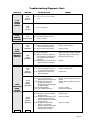
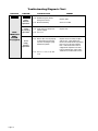
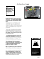
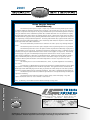
5
-AINTENANCEAND3ERVICE-ANUAL
:$51,1*
0DQ
0ROVIDING!CCESSTOTHE7ORLD
O
¤
¤
5
¤
%NTERVAN))
5HDGPDQXDO
EHIRUHVHUYLFLQJ
)DLOXUHWRGRVR
PD\UHVXOWLQ
VHULRXVERGLO\
LQMXU\DQGRU
SURSHUW\GDPDJH
¤
"RAUN%NTERVAN))
)NTERNATIONAL#ORPORATE(DQRS0/"OX7INAMAC).53!
4(%,)&4&!8
.OVEMBER
XD
%.4%26!./0%2!4)/.15)#+2%&%2%.#%'5)$%
(QWHUYDQ2SHUDWLRQ2YHUYLHZ
&RQWUROVZLWFKHVGLVSOD\WKHVOLGH
GRRUJUDSKLF
7KLVRYHUYLHZSURYLGHVDVLPSOLILHGH[SODQDWLRQRI
(QWHUYDQRSHUDWLRQ5HDGWKHHQWLUHRZQHU
V
RSHUDWRU
VPDQXDOIRUFRPSOHWHGHWDLOV&RQWDFW
7KH%UDXQ&RUSRUDWLRQDW7+(/,)7LIDQ\
RIWKLVLQIRUPDWLRQLVQRWXQGHUVWRRG
2QH7RXFK&RQWURO$FWLYDWLRQ
(QWHUYDQSRZHUGRRUUDPSDQGNQHHOIXQFWLRQV
DUHDFWLYDWHGE\SUHVVLQJDQGUHOHDVLQJDQ\
FRQWUROVZLWFK
3RZHU2SHUDWLRQ
(QWHUYDQSRZHUIXQFWLRQVDUHPDQDJHGE\WKH
2QH7RXFKHOHFWURQLFFRQWUROV\VWHP7KHFRQWURO
V\VWHPFDQEHDFWLYDWHGXVLQJWKH&KU\VOHU
UHPRWHNH\OHVVHQWU\
WUDQVPLWWHURUDQ\RQH
RIILYHLQWHULRU
PRXQWHGFRQWURO
VZLWFKHV
&KU\VOHU
2SHQ)XQFWLRQV:KHQDFWLYDWLQJWKH2SHQ
IXQFWLRQVWKHSRZHUGRRURSHQVWKHNQHHO
V\VWHPORZHUVWKHUHDURIWKHYHKLFOHDQGWKH
UDPSXQIROGV
&ORVH)XQFWLRQV:KHQDFWLYDWLQJWKH&ORVH
IXQFWLRQVWKHUDPSIROGVWKHNQHHOV\VWHPUDLVHV
WKHUHDURIWKHYHKLFOHDQGWKHSRZHUGRRUFORVHV
3UHVV
DQG
UHOHDVH
WKLV
VZLWFK
5HPRWH
.H\OHVV
(QWU\
7UDQVPLWWHU
0DQXDO2SHUDWLRQ
,QHYHQWRISRZHURUHTXLSPHQWIDLOXUHWKHGRRU
UDPSDQGNQHHOV\VWHPFDQEHPDQXDOO\RSHU
DWHG5HDGWKHRSHUDWRU
VIRUIXUWKHUGHWDLOV
%.4%26!./0%2!4)/.15)#+2%&%2%.#%'5)$%
2SHUDWLQJ7KH%UDXQ(QWHUYDQ&RXOGQ·W%H6LPSOHU
$QGWKHVOLGLQJGRRURSHQV
-XVWSUHVVDQ\RQH
RIWKHEXWWRQVOLNHWKH
RQHSLFWXUHGDERYH
7KHUHDUVXVSHQVLRQ
ORZHUV
$OORZLQJ
HDV\
HQWUDQFH
/
)2
81
7KHUDPS
XQIROGV
'
Contents
Maintenance and Service Requirements .................................................................... 2
Safety Precautions ........................................................................................................ 2
Maintenance and Lubrication Schedule .................................................................. 3-5
Troubleshooting
Troubleshooting Diagnosis Chart ........................................................................... 6-10
Auxiliary Power Source .............................................................................................. 11
Below-Floor Obstructions .......................................................................................... 12
Series 01 Wiring Diagram ............................................................................... 13A, 14A
Series 01 Electrical Schematic ....................................................................... 13B, 14B
Series 02 Wiring Diagram ............................................................................... 15A, 16A
Series 02 Electrical Schematic ....................................................................... 15B, 16B
Series 03 Wiring Diagram ............................................................................... 17A, 18A
Series 03 Electrical Schematic ....................................................................... 17B, 18B
Repair Parts
Outside Key Entry Assembly ..................................................................................... 19
29" Power Ramp Motor Assembly - Stationary.......................................................... 20
29" Power Ramp Assembly - Stationary .................................................................... 21
29" Power Ramp Motor Assembly - Swing ................................................................ 22
29" Power Ramp Assembly - Swing .......................................................................... 23
29" Manual Ramp Assembly - Stationary ............................................................ 24, 25
29" Manual Ramp Assembly - Swing ................................................................... 26, 27
30" Manual Ramp Assembly - Stationary ............................................................ 28, 29
Kneel Actuator Assembly ........................................................................................... 30
Kneel Actuator Manual Release Assembly ................................................................ 31
Specifications .............................................................................................................. 32
Dimensions .................................................................................................................. 33
Warranty ................................................................................................................. 34, 35
Return Authorization Procedure ................................................................................ 35
Page 1
Maintenance and Service Requirements
Braun Entervans must be
maintained and serviced by a
Braun authorized service representative who has attended and
been certified by The Braun
Corporation Sales and Service
School for Braun Mobility Products.
Read and become familiar with
the operating procedures outlined in the Entervan operator’s
manual and the maintenance
and troubleshooting information
contained in this manual before
beginning operation, maintenance or service procedures.
Contact The Braun Corporation
at 1-800-THE LIFT if any of this
information is not understood.
One-Touch Control System
Entervan power functions are
managed by the One-Touch
electronic control system. The
control system can be activated
using the Chrysler remote
keyless entry transmitter or any
of the interior-mounted control
switches.
Braun Corporation Aftermarket
Control Systems Policy: The
Braun Corporation manufactures
dedicated control systems for its
products. These control systems
have been designed and tested
for use in conjunction with
specific Braun products. Braun
control systems are the only
control systems authorized for
use with Braun products.
Do not attempt to interface
aftermarket control systems
without authorization from The
Braun Corporation. To do so
may result in serious bodily
injury and/or property damage.
Safety Precautions
WARNING
Read this manual,
the Entervan
operator’s manual
and supplements
before performing
operation, maintenance or service
procedures. Failure
to do so may result
in serious bodily
injury and/or property damage.
WARNING
Maintenance and service procedures must be performed
only by authorized service personnel.
WARNING
Perform maintenance and lubrication procedures exactly as
outlined in the Maintenance and Lubrication Schedule
contained in this manual.
WARNING
Perform troubleshooting and service procedures as outlined
in this manual and/or service bulletins supplied with replacement parts.
WARNING
Replacement parts must be Braun authorized replacements.
WARNING
Do not attempt to interface aftermarket control systems
without authorization from The Braun Corporation.
WARNING
Do not use accessory devices not authorized by The Braun Corporation.
WARNING
Keep clear of area in which the vehicle kneels (lowers).
WARNING
Keep clear of area in which ramp folds and unfolds.
WARNING
Never modify (alter) a Braun Corporation Entervan.
WARNING
Do not install a raised top on an Entervan.
WARNING
Failure to follow these safety precautions may result in serious bodily injury and/or
property damage.
Page 2
Maintenance and Lubrication Schedule
Normal vehicle maintenance must
be performed as outlined in the
DaimlerChrysler-supplied owner’s
manual. This maintenance is not
the responsibility of The Braun
Corporation. Refer to the Warranty section of this manual for
details regarding The Braun
Corporation Entervan Warranty.
damage, wear or any abnormal
condition. Contact your sales
representative or call The Braun
Corporation at 1-800-THE LIFT.
One of our national Product
Support representatives will direct
you to an authorized service
technician who will inspect your
Entervan.
The maintenance and lubrication
procedures specified in this
schedule must be performed by a
Braun authorized service representative at the scheduled
intervals according to the number
of cycles or elapsed time, whichever comes first.
Lubrication: Entervan ramps are
equipped with sealed bearings
and Teflon™ bushings that do not
require lubrication. Coated ramp
and kneel system chains do not
require lubrication as well.
Discontinue Entervan use
immediately if maintenance and
lubrication procedures are not
properly performed, or if there is
any sign of improper operation,
4 Weeks
or 100
Cycles
Light penetrating oil (30 weight or
equivalent) should be applied
where *Light Oil is indicated.
LPS2 General Purpose Penetrating Oil is recommended by and
available from The Braun Corporation. Eleven ounce aerosol
WARNING
Maintenance and
lubrication procedures must be performed as specified
by an authorized
service technician.
Failure to do so may
result in serious
bodily injury and/or
property damage.
cans can be ordered under part
number 15807. Severe conditions (weather, environment,
heavy usage, etc.) may require
more frequent lubrication.
When replacing lubed components, be sure to lubricate
during installation procedures.
Outboard ramp extension hinge
Clean and lubricate with *Light Oil
Kneel actuator manual release assembly
Apply *Light Oil in T-handle receptacle.
Swing-Out Ramp latch (if equipped)
Clean and lubricate with *Light Oil. Inspect for
proper operation, wear or damage.
Lower power slide door track
Inspect for obstructions and clean
Wheelchair and occupant restraint belts
Inspect for any defects such as cuts, fraying or
any malfunction of belt, buckle or securement
hardware. Replace immediately if defective.
Inspect removable seat bases for proper
engagement of latching mechanisms
Replace or correct as needed
Inspect ramp inboard pivot points (mounting
Tighten, replace or correct as needed
bolts and bushings) for positive securement,
wear or damage
Inspect ramp fold pick-up bearing for positive
Tighten, replace or correct as needed
securement, alignment, wear or other damage
continued
Inspect ramp fold arm bearing slot for excessive
wear or damage
Replace if needed
Page 3
Maintenance and Lubrication Schedule
continued
4 Weeks
or 100
Cycles
Inspect ramp extension chain for proper
alignment, securement or other defects.
Realign, resecure, replace or otherwise correct
as needed.
Inspect ramp floor mounting hardware for
securement (loose or missing)
Resecure, replace or correct as needed
Inspect cotter pin securing top pivot (wall
mounting) bracket pin
Resecure, replace or correct as needed
Perform all procedures listed in previous section also
Power Ramps: Remove ramp motor cover
and inspect:
• Top pivot (wall mounting) bracket mounting
bolts for securement (loose or missing)
• Motor mounting bolts for securement (loose
or missing)
• Ramp fold arm securement (collar and
mounting screws)
• Microswitches securement and adjustment
• Microswitch wires and terminals for securement or damage
Resecure, adjust microswitches, replace
defective parts or otherwise correct as needed.
Note: See Ramp Motor Assembly exploded
views on pages 20 and 22.
Manual Ramps: Remove torsion spring cover
and inspect:
1 Year
or
1250
Cycles
• Top pivot (wall mounting) bracket mounting
bolts for securement (loose or missing)
• Spring housing mounting bolts for securement (loose or missing)
• Ramp fold arm securement (collar and
mounting screws)
• Torsion spring securement external snap
ring (loose or missing)
Resecure, replace defective parts or otherwise
correct as needed. Note: See Manual Ramp
exploded views on pages 24-29.
Inspect Kneel actuator assembly for:
• Actuator mounting pins securement (loose
or missing hairpin cotter or “R” clip)
• Inspect chain for misalignment, wear or
damage
• Inspect chain cotter pins for securement
• Inspect chain aluminum idler (pulley) for
securement, wear, damage or misalignment
• Inspect electrical harnesses for positive
connections, proper routing, wear or other
damage
• Release cable securement (turnbuckle
connection at motor and jam nuts)
• Release cable alignment, routing, kinks,
wear, or other damage
Page 4
Realign, resecure or replace defective parts or
otherwise correct as needed. Note: See Kneel
Actuator Assembly exploded view on page 31.
Maintenance and Lubrication Schedule
Inspect power source (Series 01 and 02: OEM
battery, 30 ampere circuit breaker and dashmounted fuse block - Series 03: Floor-mounted
fuse block)
Resecure, repair or replace
Swing-Out Ramp system (if equipped) - inspect:
1 Year
or
1250
Cycles
• Latch for proper operation (apply *Light Oil)
• Latch mounting hardware for positive
securement (loose or missing mounting
hardware)
• Swing-Out latch pin (bolt assembly) for
positive securement, wear, misalignment, or
other damage
• Missing or damaged ramp top pivot bracket
securement cotter pin (hairpin cotter or “R”
clip)
• Top and/or bottom ramp pivot points (axles
and/or bearing surfaces) for deformation,
wear or other damage
• Bottom ramp pivot pin (axle) flat washer
damaged or missing.
• UHMW floor guide (button) damaged or
missing.
• Release cable for positive securement,
alignment, wear, or other damage
• Release assembly for positive securement,
deformation, or other damage
• Does release seat properly in the slotted
housing? See Cable Adjustment if release
lever seats before positive latching.
Realign, resecure, tighten, lubricate, replace
defective parts or otherwise correct as needed.
Cable Adjustment: Remove threshold and lift
carpet above latch to access two latch mounting bolts. Cable attachment bracket is
equipped with adjustment oval slots. Loosen
mounting bolts, adjust cable and bracket as
needed and resecure.
Page 5
Troubleshooting Diagnosis Chart
WARNING
Troubleshooting and
repair procedures
must be performed
as specified by an
authorized service
technician only.
Failure to do so may
result in serious
bodily injury and/or
property damage.
FUNCTION
The cause of the problem can be
determined by locating the
function and related symptom in
SYMPTOM
1.10
No Power
To Entervan
Systems
1.00
NO
OPERATION
If a problem occurs with your
Entervan, discontinue operation
immediately! Do not attempt
repairs yourself. Contact your
sales representative or call The
Braun Corporation at 1-800-THE
LIFT. One of our national Product Support representatives will
direct you to an authorized
service technician who will
inspect your Entervan.
(Circuit Problem)
1.20
Power to
Entervan
Systems
But No
Operation
POSSIBLE CAUSE
2.00
KNEEL
SYSTEM
(LOWER)
2.20
Faulty
Kneel
(Lower)
Operation
Page 6
A Repair Parts section with
exploded views and corresponding parts lists is also provided.
Correct the problem if possible.
If the problem continues,
contact The Braun Corporation.
REMEDY
Poor ground connection
Battery terminals dirty
Battery defective
Battery discharged
12 volt source (check fuses for 12
volts)
1.16 Circuit breaker tripped or faulty
Clean and tighten
Clean and tighten
Replace
Charge battery
Check for blown fuse, loose terminals
or broken wire or cable
Reset or Replace
1.21
1.22
1.23
1.24
1.25
1.26
Engage transmission in Park
Clean and tighten
Repair or replace
Crimp tightly to wire
Replace
Reset or replace
1.11
1.12
1.13
1.14
1.15
Transmission not in Park
Loose connection
Broken wire
Wire terminal
Control switch defective
Braun One-Touch Controller
2.11 See 1.00
2.12 Kneel On-Off feature turned off
2.10
No
Lower
Operation
the Troubleshooting Diagnosis
Charts. The specific cause and
remedy can then be determined
by process of elimination. Electrical Schematics and Wiring
Diagrams are provided to aid in
troubleshooting.
2.13 Kneel actuator brake manually
released with “T-handle” or other
kneel actuator manual release
problem.
2.14 Actuator harness disconnected,
damaged or otherwise defective
2.15 Actuator defective
2.16 Chain disconnected, damaged or
otherwise defective
2.21 Mechanical binding
2.22 Misalignment or damage to kneel
system components. Inspect
kneel actuator assembly for:
• Actuator mounting pins/hairpin
cotter (“R” Clip) securement
(loose or missing)
• Inspect chain for wear, misalignment, or other damage
• Inspect chain aluminum idler for
securement, wear, damage or
misalignment
Turn kneel on. Press and hold driver
side dash control switch a minimum of
three seconds (Entervan power
functions must be in closed mode).
Correct or repair as needed
Connect, repair or replace
Replace
Connect, repair or replace
Check and correct
Connect, replace or otherwise correct
as needed
Troubleshooting Diagnosis Chart
FUNCTION
SYMPTOM
3.10
No
Open
Operation
(Motor Does
Not Run)
3.00
POWER
DOOR
(OPEN)
3.20
Motor Runs
But Door
Does Not
Move
3.13 Door microswitch(es) defective
3.14 Door operator motor harness
disconnected or defective
3.15 Door operator motor defective
Check for obstructions, then manually
close door.
See DaimlerChrysler Service Center
See DaimlerChrysler Service Center
See DaimlerChrysler Service Center
See DaimlerChrysler Service Center
3.31 Obstruction in door path
3.32 Mechanical binding
Remove obstruction
Check and correct
3.40
Door Does
Not Open
Fully
3.41 Door Opened microswitch out of
adjustment or defective
3.42 Door latch not engaging door
opened striker
3.43 See 3.30
See DaimlerChrysler Service Center
4.10
No
Unfold
Operation
4.11 See 1.00
4.12 Door Opened microswitch
defective
4.13 Ramp motor harness disconnected or defective
4.14 Loose, damaged or missing fold
arm securement collar and/or
screws
4.15 Ramp Unfolded microswitch out of
adjustment or defective
4.16 Ramp motor defective
4.20
Ramp
Contacts
Door
4.30
Faulty
Unfold
Operation
continued
3.11 See 1.00
3.12 Door not fully closed
REMEDY
3.21 Misaligned or otherwise damaged
motor gear or door gear rack
3.30
Faulty
Open
Operation
4.00
RAMP
UNFOLD
POSSIBLE CAUSE
continued
Check for obstructions and/or damaged
components
See DaimlerChrysler Service Center
Connect, repair or replace
Tighten, replace or otherwise correct as
needed
Adjust or replace
Replace motor
4.21 Door not fully open
4.22 Swing-Out Ramp latch (if
equipped) not fully engaged
(ramp not latched)
4.23 Misalignment of slide door striker
See DaimlerChrysler Service Center
Engage latch fully or repair Swing-Out
Ramp latch system
4.31 Ramp Unfolded microswitch
harness disconnected or
defective
4.32 Ramp Unfolded microswitch out of
adjustment or defective
4.33 Misalignment or damage to:
• Ramp fold bearing
• Ramp fold arm
• Ramp fold arm bearing slot
• Ramp pivot points or hinge(s)
4.34 Mechanical binding
Connect, repair or replace
Adjust or replace
Adjust or replace
Realign, tighten, replace defective parts
or otherwise correct as needed
Check and correct
Page 7
Troubleshooting Diagnosis Chart
FUNCTION
SYMPTOM
continued
continued
4.00
RAMP
UNFOLD
5.00
RAMP
FOLD
4.30
Faulty
Unfold
Operation
4.40
Faulty Ramp
Extension
Unfold
POSSIBLE CAUSE
4.35 See 4.15
4.41 Ramp extension chain broken,
detached, misaligned or otherwise
defective
4.42 Lack of lubrication
5.10
No
Fold
Operation
5.11 See 1.00
5.12 Ramp Folded microswitch out of
adjustment or defective
5.13 See 4.12, 4.13, 4.14 and 4.16
5.20
Faulty
Fold
Operation
5.21 Ramp Folded microswitch harness
disconnected or defective
5.22 Fold arm support/stop out of
adjustment
5.23 See 4.14, 4.15, 4.33, 4.34, and
4.42
6.10
No
Close
Operation
REMEDY
6.11 See 1.00 and 3.10
6.12 Ramp motor harness disconnected or defective
6.13 Ramp folded microswitch out of
adjustment or defective
6.14 Door not fully open
6.15 Door microswitch(es) defective
Replace, attach, realign or otherwise
correct
Lubricate - See Maintenance and
Lubrication Schedule
Adjust or replace
Connect, repair or replace
Adjust support/stop for more travel
Connect, repair or replace
Adjust or replace
Open door fully to engage striker with
door opened latch
See DaimlerChrysler Service Center
6.20
Motor Runs - Door
Does Not Move
6.00
POWER
DOOR
(CLOSE)
6.30
Faulty
Operation
6.40
Door Does
Not Close
Fully
6.50
Door Contacts
Ramp When
Closing
Page 8
6.21 See 3.20
6.31 See 3.30
6.41 See 3.30
6.51 Outboard ramp extension hinge
not properly lubricated, obstructed
or otherwise damaged
6.52 See 5.22 and 6.13
Clean and lubricate with *Light Oil,
remove obstruction or otherwise correct
Troubleshooting Diagnosis Chart
FUNCTION
7.00
KNEEL
SYSTEM
(RAISE)
SYMPTOM
POSSIBLE CAUSE
7.10
7.11 See 1.00, 2.14, 2.15, 2.16 and
2.20
No Raise
Operation
7.20
Faulty
Operation
8.00
REMOTE
CONTROL
9.00
KNEEL
ACTUATOR
MANUAL
RELEASE
10.00
SWING OUT
RAMP
SYSTEM
(if equipped)
8.10
No Operation
7.21 See 2.13 and 2.20
8.11 See DaimlerChrysler vehicle
owner’s manual
9.11 Manual release T-handle missing
9.12 Release cable broken, disconnected, or otherwise defective
9.13 Kneel actuator brake defective
Replace
Connect, repair or replace
9.21 Lack of lubrication
9.22 Release cable out of adjustment,
out of alignment, routing obstruction, kinked, worn or otherwise
damaged
9.23 Manual release T-handle threads
stripped or otherwise damaged
Apply *Light Oil in T-handle receptacle.
Adjust, align, reroute, remove kinks,
otherwise repair or replace
10.10
No
Release
Operation
10.11 Release cable broken, disconnected or otherwise defective
10.12 Faulty Swing-Out Ramp latch
(will not disengage)
Connect or replace cable
10.20
Faulty
Release
Operation
10.21 Loose, worn or otherwise
damaged Swing-Out Ramp latch
10.22 Missing, loose, worn, bent,
misaligned or otherwise
damaged Swing-Out Ramp latch
pin (bolt assembly)
10.23 Mechanical binding
10.24 Lack of lubrication to latch
Tighten, replace or otherwise correct as
needed
Tighten, replace or otherwise correct as
needed
10.31 Missing PVC washer at bottom
pivot point (axle)
10.32 Misalignment, deformation, wear
or other damage to top and/or
bottom pivot points (axles and/or
bearing surfaces)
10.33 Misalignment, deformation,
looseness, wear or other
damage to inboard ramp support
weldment, or floor and lower
slide door track assembly
Replace washer
9.10
No
Operation
9.20
Faulty
Operation
10.30
Faulty
Rotation
Operation
continued
REMEDY
Replace actuator
Replace
Replace latch
Correct as needed
Lubricate with *Light Oil
Correct as needed
Correct as needed
continued
Page 9
Troubleshooting Diagnosis Chart
FUNCTION
continued
SYMPTOM
10.40
No Latching
Operation
10.50
Faulty
Latching
Operation
10.34 UHMW floor guide (button)
damaged or missing.
10.35 Mechanical binding
Replace guide
10.41 Faulty Swing-Out Ramp latch
(will not engage)
10.42 See 10.20
Replace latch
10.51 Release does not seat properly
in slotted housing preventing
latch from returning to springloaded latch position
Replace release assembly or adjust
cable at latch. Cable Adjustment:
Remove threshold and lift carpet above
latch to access two latch mounting
bolts. Cable attachment bracket is
equipped with adjustment oval slots.
Loosen mounting bolts, adjust cable
and bracket as needed and resecure.
10.52 See 10.11, 10.20, 10.33 and
10.41
Page 10
REMEDY
continued
10.30
Faulty
Rotation
Operation
10.00
SWING OUT
RAMP
SYSTEM
(if equipped)
POSSIBLE CAUSE
Correct as needed
Auxiliary Power Supply
CAUTION
25 Ampere Fuse
Female Spade Terminal
Do not connect
auxiliary devices to
vehicle battery. Doing
so may result in
damage to electrical
system and/or electronic components.
Series 03 Floor Mounted Fuse Block
Do not connect auxiliary devices directly to the
vehicle battery. Doing so may result in damage
to electrical system and/or electronic components.
A fuse block that can accommodate up to five
additional ATO® type fuses is provided as an
auxiliary power source. This power source is
available for installation of a dealer-installed power
seat, an electric tie-down or other auxiliary electrical device(s).
The fuse block is located behind the dash below
the steering column in Series 01 and Series 02
Entervans. The fuse block is located on the floor
below the dash center console in Series 03 Entervans (shown in photo). Remove the plastic cover
to access the fuse block.
The installer is responsible for supplying the
correct gauge wire and fuse for the particular
device to be attached to the fuse block (as specified by the manufacturer of the device). The
maximum load must not exceed 25 amperes.
WARNING
Wires with female fully-insulated terminals can
simply be connected to one of five available
terminals on the fuse block. A female terminal and
25 ampere fuse are provided at top right fuse
position for this purpose (as shown).
Note: A 30 ampere fuse is factory installed in the
top left receptacle for protection of the One-Touch
electronic control module. Fuses installed in all
other fuse positions must not exceed 25 amperes.
Note: If installing an auxiliary electrical device
that requires more than a 25 ampere power
source, an alternative power source must be
provided. Refer to the Electrical Schematics and
Wiring Diagrams contained in this manual.
Risk of electrical fire!
Install and electrically
terminate Auxiliary
electrical device as
specified by device
manufacturer.
Page 11
Below-Floor Obstructions
Below-Floor Obstructions
When installing an
electrical tie-down, power
seat or other auxiliary
electrical device in an
Entervan, obstructions
below the floor must be
avoided. Obstructions
include wiring, fuel
system, brake lines, etc.
Installers must be aware
of these obstructions.
Note: Series 03 Entervan depicted.
Front Seat
Wiring
Harness
Recepticle
Station
and
Fuse Block
effective
9-17-01
WARNING
Check for obstructions such as wires,
gas lines, exhaust,
etc. before drilling or
cutting through floor.
Failure to do so may
result in serious
bodily injury and/or
property damage.
Refer to the illustration
when installing aftermarket
equipment to avoid contacting or damaging vital
components under the
floor. Drilling or cutting
into such obstructions
may result in potential
hazards as well as
property damage.
Note: Some wiring
harnesses shown may not
be present. Avoid all
harness locations.
Charcoal
Canister
O.E.M.
Wiring
Braun
Wiring
Braun/OEM
Wiring
Fuel
System
Brake
System
Emergency
Brake
Cables
Heat
and
A/C
Brake
Lines
Fuel
Filter
Liquid/Vapor
Separator
Fuel System
Emission
Lines
Rear Heat
Lines
Brake
Lines
Rear A/C
Lines
Fuel Fill
Hose
Proportioning
Valve
Main Fuel Line
(Tank to Filter)
Fuel Return
Line
Fuel
Tank
Main Fuel Line
(Filter to Engine)
Series 01 Wiring Diagram
P / J4
P5
E50053A
BK
BL / BK #211
R
W #1
BK #201
Ground
R #2C3
Connects to
Vehicle Battery
(+) Positive Post
One-Touch
Controller
52850-0101
(w/o Sleep Mode)
OR (14 GA.)
OR (14 GA.)
30 Amp
Fuse
R 10 GA.
P6
8
7
6
5
4
3
2
12
6
11
5
10
4
9
3
8
2
7
1
12
11
10
9
8
7
6
5
4
3
2
1
1
2
3
4
5
6
7
8
9
1 2 3
4 5 6
7 8 9
3
2
1
6
5
4
9
8
7
3 2 1
6 5 4
9 8 7
12-COND WIRE CODE
NO.
1
R 10 GA.
9-COND WIRE CODE
COLOR
9-COND WIRE CODE
1
WHITE (9 COND.)
NO.
COLOR
NO.
2
GREEN (9 COND.)
1
NOT USED
1
NOT USED
NOT USED
COLOR
3
VIOLET (9 COND.) & VIOLET (20GA.)
2
BLUE (9 COND.)
Circuit
Breaker
8 7 6 5 4 3 2 1
2
4
WHITE (20 GA.)
3
YELLOW (9 COND.)
3
YELLOW (9 COND.)
5
NOT USED
4
ORANGE (9 COND.)
4
ORANGE (9 COND.)
6
ORANGE (9 COND.)
5
BROWN (9 COND.)
5
BROWN (9 COND.)
(30 Amp.)
8-COND WIRE CODE
7
BROWN (9 COND.)
6
BLACK (9-COND.)
8
BLACK (9 COND.)
7
WHITE (9-COND.)
F7
BAT.
F10
25
F8
F11
F9
F12
Aux.
E50179A
NO.
COLOR
1
#210 ORANGE / BLACK
2
#26 WHITE / RED / ORANGE
3
ORANGE (14 GA.) FUSE HOLDER
4
NOT USED
5
NOT USED
6
#201 BLACK
7
#1 WHITE
8
#211 BLUE / BLACK
9
BLUE (9 COND.)
8
VIOLET (9-COND.)
10
NOT USED
9
GREEN (9 COND.)
11
BLACK (20 GA.)
12
YELLOW (9 COND.)
P / J1
Front Fuse Block
6
BLACK (9 COND.)
7
WHITE (9 COND.)
8
VIOLET (20 GA.)
9
NOT USED
E50054A
E50053A
E50057A
N.C.
C-H
N.O.
#1 W
NC
S
NO
V (20 GA.)
COM
#207 W / BK
6-COND WIRE CODE
NO.
COM.
Ramp Folded
Microswitch
N.C.
#201 BK
N.O.
C-H
NC
S
NO
COM
#207 W / BK
Wall-Mounted
Open / Close
Switch
E50178??
E50053A
Ramp Motor
and
Gear Box
Dash-Mounted
Open / Close
Switch
E50060??
WHITE (9 COND.)
2
ORANGE (9 COND.)
4
BLACK (9 COND.)
5
YELLOW (9 COND.)
6
NOT USED
32 1
32 1
W (20 GA.)
W (10 COND.)
BK (10 COND.)
P / J2
Y
#210 OR / BK
BN (10 COND.)
NO.
OR (10 COND.)
V (20 GA.)
#26 W / R / OR
52038A-96A8
2
3
4
5
6
1 2 3
4 5 6
3
2
1
6
5
4
3 2 1
6 5 4
6-COND WIRE CODE
V (20 GA.)
W (20 GA.)
BK
1
P / J7
Ramp Unfolded
Microswitch
R
BROWN (9 COND.)
3
COM.
P / J3
COLOR
1
COLOR
1
WHITE (10 COND.)
2
ORANGE (10 COND.)
3
BROWN (10 COND.)
4
BLACK (10 COND.)
5
YELLOW
6
NOT USED
W (20 GA.)
#207 W / BK
Ground
P9
3
2
1
6
5
4
3 2 1
6 5 4
9-COND WIRE CODE
1
2
3
4
5
6
1 2 3
4 5 6
COLOR
NO.
1
#26 WHITE / RED / ORANGE
1
#26 WHITE / RED / ORANGE
2
#210 ORANGE / BLACK
2
#210 ORANGE / BLACK
Page 13A
BK (10 COND.)
W (10 COND.)
BK / V
BN (10 COND.)
BK / L. GN
BK / BU
BK / TN
BK (14 GA.)
BK / RD
P8
To OEM
Body Control
Module
COLOR
#201 BLACK
3
4
#1 WHITE
4
WHITE (20 GA.)
5
#207 WHITE / BLACK
5
#207 WHITE / BLACK
6
NOT USED
6
NOT USED
BLACK (20 GA.)
1
2
3
4
5
6
7
8
9
10
1 2 3 4 5
6 7 8 9 10
10-COND WIRE CODE
Kneel Actuator
E50148A
BK / L. GN
BK / BU
BK / TN
BK (14 GA.)
BK / RD
9-COND WIRE CODE
NO.
3
Ground
To OEM
Power Slide Door
Module
OR (20 GA.)
BK / GY
BK / V
1 2 3 4 5
1
2
3
4
6
7
8
9
5
6 7 8 9 10
10
10-COND WIRE CODE
NO.
COLOR
NO.
COLOR
1
BLACK / BLUE
1
BLACK (14 GA.)
2
BLACK / TAN
2
BLACK / TAN
3
BLACK / LIGHT GREEN
3
BLACK / LT. GREEN & BROWN (10 COND.)
4
BLACK (14 GA.)
4
BLACK / BLUE
5
ORANGE (20GA.)
6
PLUG SEAL
6
NOT USED
7
BLACK / GRAY
7
BLACK (10 COND.)
8
BLACK / VIOLET
8
BLACK/VIOLET & WHITE (10 COND.)
9
PLUG SEAL
9
NOT USED
10
BLACK / RED
10
BLACK / RED
5
NOT USED
Page 14A
n
ir Ser fold
in ie
g s fo
D 0 r:
ia 1
gr
am
OR (14 GA.)
P5-3
#26 W / R / OR
P5-2
#210 OR / BK
P5-1
OR (14 GA.)
R
R
#26 W / R / OR
P3-A
BK
M
P3-B
P6-11
P6-3
P6-2
P2-2
RAMP
MOTOR
M
P6-4
P2-1
BATTERY
CIRCUIT BREAKER
#210 OR / BK
P4-1
CONNECTORS
P1-6
BK (9-COND.)
BL
BK (9-COND.)
P1-5
JUNCTION
P1-2
W (9-COND.)
BN (9-COND.)
P1-7
W (9-COND.)
BN (9-COND.)
BK (20GA)
V (20GA.)
Y (9-COND.)
#207 W / BK
W / BK (16 GA.)
3.9K
W / BK (16 GA.)
M
MOTOR
MICROSWITCH
P7-3
P7-4
BK (10 COND.)
BK (20GA.)
P7-1
P2-3
#201 BK
W (10-COND.)
V (20 GA.)
#201 BK
C
NC
16K
16K
RAMP UNFOLDED
MICROSWITCH
NO
3.9K
SWITCH
3.9K
BN (10 COND.)
#207 W/BK
P1-3
P2-5
16K
FRONT FUSE BLOCK
Y (9-COND.)
#207 W / BK
P7-5
F12
#207 W / BK
DASH-MOUNTED
OPEN / CLOSE
SWITCH
E50060??
Y (10-COND.)
F9
OR (9 COND.)
F11
P1-4
F8
WALL-MOUNTED
OPEN / CLOSE
SWITCH
E50178??
#207 W/BK
BK (20GA)
25
P7-2
F10
OR (10 COND.)
F7
FUSE
NC
V (20GA.)
#207 W/BK
10 GA. RED
W (20GA.)
C
R #2C3
30 A.
P2-4
#1 W
OR (9 COND.)
NO
P1-9
RAMP FOLDED
MICROSWITCH
P1-8
W 20GA
V (9-COND.)
#1 W
V (20 GA.)
KNEEL
MOTOR
SYMBOL
CHASSIS GROUND
BK
P4-2
#26 W / R / OR
One-Touch
Controller
52850-0101
(w/o Sleep Mode)
P6-9
P5-6
P6-8
#201 BK
DESCRIPTION
P6-7
P5-7
P6-1
P5-8
#1 W
P6-6
#2C3 R
#211 BL / BK
P6-12
#211 BL / BK
W
U
Series 01 Electric Schematic
BK (10 COND.)
P9-5
OR (20 GA.)
P9-7
BK / GY (20 GA.)
W (10 COND.)
P9-8
BK / V (20 GA.)
BK / V (20 GA.)
P8-7
P8-8
BN (10 COND.)
DRAWING SHOWN WITH:
VEHICLE IN PARK
RAMP STOWED
DOOR CLOSED
VEHICLE RAISED
Page 13B
P8-3
P9-3
BK / LT. GN (20 GA.)
BK / LT. GN (20 GA.)
P9-1
BK / BU (20 GA.)
BK / BU (20 GA.)
P8-4
P9-2
BK / TN (20 GA.)
BK / TN (20 GA.)
P8-2
P9-4
BK (20 GA.)
BK (20 GA.)
P8-1
P9-10
BK (20 GA.)
BK / RD
P8-10
Page 14B
Series 02 Wiring Diagram
P / J4
P5
E50053A
BK
#211 BL / BK
R
#1 W
#201 BK
Ground
R #2C3
Connects to
Vehicle Battery
(+) Positive Post
One-Touch
Controller
E52850-01
5
10
4
9
3
8
2
7
1
NO.
30 Amp
Fuse
R 10 GA.
6
11
P6
8
7
6
5
4
3
2
8 7 6 5 4 3 2 1
Circuit
Breaker
NO.
F10
25
F8
F11
F9
F12
Aux.
GREEN (9 COND.)
3
VIOLET (9 COND.) & VIOLET (20GA.)
WHITE (20 GA.)
5
NOT USED
6
ORANGE (9 COND.)
7
BROWN (9 COND.)
8
BLACK (9 COND.)
9
BLUE (9 COND.) & BK
2
3
4
5
6
7
8
1 2 3
4 5 6
7 8 9
9
3
2
1
6
5
4
9
8
7
3 2 1
6 5 4
9 8 7
BLACK (20 GA.)
YELLOW (9 COND.)
9-COND WIRE CODE
COLOR
9-COND WIRE CODE
1
#210 ORANGE / BLACK
NO.
COLOR
NO.
2
#26 WHITE / RED / ORANGE
1
NOT USED
1
NOT USED
3
ORANGE (14 GA.) FUSE HOLDER
2
BLUE (9 COND.)
NOT USED
2
NOT USED
4
3
YELLOW (9 COND.)
3
YELLOW (9 COND.)
4
ORANGE (9 COND.)
4
ORANGE (9 COND.)
5
BROWN (9 COND.)
6
BLACK (9-COND.)
5
NOT USED
6
#201 BLACK
7
#1 WHITE
Optional
Magnetic Entry
BK
8
#211 BLUE / BLACK
Front Fuse Block
Open / Close
E50057A
Ground Attached to Body
With Self-Tap Screw
E50053A
N.C.
1
NOT USED
11
12
W
E50179A
7
WHITE (9-COND.)
8
VIOLET (9-COND.)
9
GREEN (9 COND.)
5
6
COLOR
BROWN (9 COND.)
BLACK (9 COND.)
7
WHITE (9 COND.)
8
VIOLET (20 GA.) & VIOLET (20 GA.)
9
NOT USED
P / J1
E50054A
C-H
N.O.
#1 W
Controller E52850-01
(Revision A)
Effective: 7-17-01
• One-Touch Operation
• Sleep Mode
• Kneel On/Off Toggle
COLOR
WHITE (9 COND.)
2
10
8-COND WIRE CODE
(30 Amp.)
F7
Controller E52850-01
Effective: 4-12-01
• One-Touch Operation
• Sleep Mode
Note: Use of modified
Open/Close switches
implemented also.
6
5
4
3
2
1
1
4
1
R 10 GA.
BAT.
12
11
10
9
8
7
12-COND WIRE CODE
OR (14 GA.)
OR (14 GA.)
12
V (20 GA.)
NC
NO
COM
#207 W / BK
V (20 GA.)
6-COND WIRE CODE
NO.
COM.
NO
COM
COM.
Ramp Unfolded
Microswitch
32 1
#210 OR / BK
52038A-96A8
P / J2
32 1
Note: Passenger's
side dash switch
present on vehicles
manufactured
after 8-22-01.
BROWN (9 COND.)
4
BLACK (9 COND.)
5
YELLOW (9 COND.)
NOT USED
1
2
3
4
5
6
1 2 3
4 5 6
3
2
1
6
5
4
3 2 1
6 5 4
6-COND WIRE CODE
NO.
V (20 GA.)
W (20 GA.)
#26 W / R / OR
V (20 GA.)
W (20 GA.)
V (20 GA.)
BK
W (20 GA.)
R
P / J3
32 1
ORANGE (9 COND.)
3
P / J7
W (10 COND.)
NC
BK (10 COND.)
N.O.
#207 W / BK
COLOR
WHITE (9 COND.)
2
6
Y
#201 BK
C-H
Passenger's Side
Dash-Mounted
Open / Close
Switch
E50060M??
(modified)
BN (10 COND.)
N.C.
Wall-Mounted
Open / Close
Switch
E50178M??
(modified)
E50053A
Ramp Motor
and
Gear Box
Driver's Side
Dash-Mounted
Open / Close
Switch
E50060M??
(modified)
OR (10 COND.)
Ramp Folded
Microswitch
1
COLOR
1
WHITE (10 COND.)
2
ORANGE (10 COND.)
3
BROWN (10 COND.)
4
BLACK (10 COND.)
5
YELLOW
6
NOT USED
W (20 GA.)
#207 W / BK
P9
3
2
1
6
5
4
3 2 1
6 5 4
9-COND WIRE CODE
1
2
3
4
5
6
1 2 3
4 5 6
COLOR
NO.
1
#26 WHITE / RED / ORANGE
1
#26 WHITE / RED / ORANGE
2
#210 ORANGE / BLACK
2
#210 ORANGE / BLACK
Page 15A
BK (10 COND.)
W (10 COND.)
BK / V
BN (10 COND.)
BK / L. GN
BK / BU
BK / TN
BK (14 GA.)
BK / R
P8
To OEM
Body Control
Module
COLOR
BLACK (20 GA.)
#201 BLACK
3
4
#1 WHITE
4
WHITE (20 GA.)
5
#207 WHITE / BLACK
5
#207 WHITE / BLACK
6
NOT USED
6
NOT USED
1
2
3
4
5
6
7
8
9
10
1 2 3 4 5
6 7 8 9 10
10-COND WIRE CODE
Kneel Actuator
OR (20 GA.)
BK / GY
BK / V
BK / L. GN
BK / BU
BK / TN
BK (14 GA.)
BK / R
9-COND WIRE CODE
NO.
3
Ground
To OEM
Power Slide Door
Module
Ground
E50148A
1
2
3
4
6
7
8
9
5
1 2 3 4 5
6 7 8 9 10
10
10-COND WIRE CODE
NO.
COLOR
NO.
COLOR
1
BLACK / BLUE
1
BLACK (14 GA.)
2
BLACK / TAN
2
BLACK / TAN
3
BLACK / LIGHT GREEN
3
BLACK / LT. GREEN & BROWN (10 COND.)
4
BLACK (14 GA.)
4
5
ORANGE (20GA.)
6
PLUG SEAL
6
NOT USED
7
BLACK / GRAY
7
BLACK (10 COND.)
8
BLACK / VIOLET
8
BLACK/VIOLET & WHITE (10 COND.)
9
PLUG SEAL
9
NOT USED
10
BLACK / RED
10
BLACK / RED
5
BLACK / BLUE
NOT USED
Page 16A
n
ir Ser fold
in ie
g s fo
D 0 r:
ia 2
gr
am
W
U
Series 02 Electric Schematic
#211 BL / BK
P5-8
P6-11
P6-3
CHASSIS GROUND
CIRCUIT BREAKER
CONNECTORS
W (9-COND.)
BN (9-COND.)
BK (9-COND.)
BU
P1-7
P1-5
P1-6
P1-2
W (9-COND.)
BN (9-COND.)
BK (9-COND.)
BK
Y (9-COND.)
JUNCTION
#201 BK
BK (20GA.)
P7-4
V (20 GA.)
P2-3
NC
BK (10 COND.)
C
P7-3
W / BK (16 GA.)
#201 BK
P7-1
NO
W (10-COND.)
RAMP UNFOLDED
MICROSWITCH
MOTOR
M
BK (20GA)
SWITCH
MICROSWITCH
BN (10 COND.)
W / BK (16 GA.)
P7-5
#207 W / BK
Y (10-COND.)
FRONT FUSE BLOCK
#207 W / BK
DRIVER'S SIDE
DASH-MOUNTED
OPEN / CLOSE
SWITCH E50060M??
(modified)
P7-2
#207 W / BK
F12
P2-5
V (20 GA.)
#207 W/BK
W / BK (16 GA.)
WALL-MOUNTED
OPEN / CLOSE
SWITCH E50178M??
(modified)
25
#207 W/BK
F9
F10
F11
BATTERY
BK
V (20 GA.)
F8
P1-3
PASSENGER'S SIDE
DASH-MOUNTED
OPEN / CLOSE
SWITCH E50060M??
(modified)
P1-8
Note: Passenger's
side dash switch
present on vehicles
manufactured
after 8-22-01.
P1-9
W
NC
10 GA. RED
F7
SYMBOL
C
R #2C3
30 A.
BK
DESCRIPTION
FUSE
Y (9-COND.)
#207 W/BK
NO
BK (20GA)
OPTIONAL
MAGNETIC ENTRY
(OPEN & CLOSE)
NC
P6-2
P6-4
W (20GA.)
OR (9 COND.)
P2-4
#1 W
V (20GA.)
NO
C
V (20GA.)
#1 W
#210 OR / BK
V (9-COND.)
RAMP FOLDED
MICROSWITCH
BK
M
Controller E52850-01
(Revision A)
Effective: 7-17-01
• One-Touch Operation
• Sleep Mode
• Kneel On/Off Toggle
W (20GA.)
R
P3-B
GN (9-COND.)
P3-A
R
#26 W / R / OR
P4-1
P2-2
RAMP
MOTOR
M
P1-4
P4-2
BK
P2-1
KNEEL
MOTOR
P6-9
P5-1
P6-8
P5-2
#210 OR / BK
P6-7
#26 W / R / OR
Controller E52850-01
Effective: 4-12-01
• One-Touch Operation
• Sleep Mode
Note: Use of modified
Open/Close switches
implemented also.
One-Touch Controller
E52850-01
P6-1
P5-3
P6-6
P5-6
P6-12
#201 BK
OR (14 GA.)
OR (14 GA.)
#26 W / R / OR
P5-7
OR (9 COND.)
#2C3 R
#1 W
OR (10 COND.)
#211 BL / BK
#1 W
BK (10 COND.)
P9-5
OR (20 GA.)
P9-7
BK / GY (20 GA.)
W (10 COND.)
P9-8
BK / V (20 GA.)
BK / V (20 GA.)
P8-7
P8-8
BN (10 COND.)
DRAWING SHOWN WITH:
• VEHICLE IN PARK
• RAMP STOWED
• DOOR CLOSED
• VEHICLE RAISED
Page 15B
P8-3
P9-3
BK / LT. GN (20 GA.)
BK / LT. GN (20 GA.)
P9-1
BK / BU (20 GA.)
BK / BU (20 GA.)
P8-4
P9-2
BK / TN (20 GA.)
BK / TN (20 GA.)
P8-2
P9-4
BK (14 GA.)
BK (20 GA.)
P8-1
P9-10
BK / R (14 GA.)
BK / R (14 GA.)
P8-10
Page 16B
Series 03 Wiring Diagram
P5
E50053A
One-Touch
Controller
E52850-01
#201 BK
Ground
6
5
4
3
2
1
8 7 6 5 4 3 2 1
To Intelligent Power Module
E50057A
8
BLACK (9 COND.)
9
BLUE (9 COND.) & BK
NOT USED
11
BLACK (20 GA.)
12
YELLOW (9 COND.)
#210 ORANGE / BLACK
2
#26 WHITE / RED / ORANGE
3
ORANGE (14 GA.) FUSE HOLDER
4
NOT USED
5
6
W
N.C.
NC
NOT USED
#1 WHITE
8
#211 BLUE / BLACK
9-COND WIRE CODE
1
5
4
9
8
7
3 2 1
6 5 4
9 8 7
9-COND WIRE CODE
NO.
1
2
BLUE (9 COND.)
2
BLUE (4 COND.)
3
YELLOW (9 COND.)
3
YELLOW (9 COND.)
4
ORANGE (9 COND.)
4
ORANGE (9 COND.)
5
BROWN (9 COND.)
6
BLACK (9-COND.)
Open / Close
Note: Magnetic Entry wire
color coding and termination
revised 11-26-01. See Series
02 for prior configuration.
7
WHITE (9-COND.)
8
VIOLET (9-COND.)
9
GREEN (9 COND.)
COLOR
NOT USED
BROWN (9 COND.)
5
BLACK (9 COND.)
6
7
WHITE (9 COND.)
8
VIOLET (20 GA.) & VIOLET (20 GA.)
9
NOT USED
P / J1
E50054A
V (20 GA.)
V (20 GA.)
N.O.
C-H
NC
S
NO
COM
Driver's Side
Dash-Mounted
Open / Close
Switch
E50060M??
(modified)
Wall-Mounted
Open / Close
Switch
E50178M??
(modified)
E50053A
N.C.
V (20 GA.)
32 1
Note: Passenger's
side dash switch
present on vehicles
manufactured
after 8-22-01.
#210 OR / BK
P / J2
Note: Key entry
present on vehicles
manufactured
after 10-19-01.
COLOR
1
WHITE (9 COND.)
2
ORANGE (9 COND.)
BROWN (9 COND.)
4
BLACK (9 COND.)
5
YELLOW (9 COND.)
6
NOT USED
P / J7
Key Entry
Microswitches
1
2
3
4
5
6
3
2
1
6
5
4
1 2 3
4 5 6
3 2 1
6 5 4
6-COND WIRE CODE
NO.
C NO NC
GY
BK
V (20 GA.)
W (20 GA.)
#26 W / R / OR
32 1
W (20 GA.)
V (20 GA.)
32 1
NO.
3
BU
W (20 GA.)
Ramp Unfolded
Microswitch
6-COND WIRE CODE
BU (4 COND.)
Passenger's Side
Dash-Mounted
Open / Close
Switch
E50060M??
(modified)
COM.
52038A-96A8
2
6
COLOR
S
#207 W / BK
BK
9
3
NOT USED
Ground
Ramp Folded
Microswitch
P / J3
8
1 2 3
4 5 6
7 8 9
1
#201 BLACK
7
COM.
R
6
NO.
COM
#207 W / BK
#201 BK
3
5
C-H
N.O.
NO
Ramp Motor
and
Gear Box
2
4
W
E50053A
#1 W
1
C NO NC
BK
BU
GY
W (10 COND.)
Front Fuse Block
BROWN (9 COND.)
BK (10 COND.)
F12
F9
7
Y
F11
NOT USED
ORANGE (9 COND.)
BN (10 COND.)
25
WHITE (20 GA.)
6
Optional
Magnetic Entry
COLOR
1
BK
30
F8
VIOLET (9 COND.) & VIOLET (20GA.)
5
BK
NO.
Note: Entervan power
source switched from
vehicle OEM battery to
OEM Power Slide Door
Module and Intelligent
Power Module feed at
fuse block E50057A
(effective 8-9-01).
F10
3
7
8-COND WIRE CODE
F7
GREEN (9 COND.)
10
To Power Slide Door Module
12 GA W/R
COLOR
WHITE (9 COND.)
2
Controller E52850-01
(Revision B)
Effective: 10-19-01
• One Touch-Operation
• Sleep Mode
• Kneel On/Off Toggle
• Key Entry
• Magnetic Entry
(functions if doors
are locked)
Controller E52850-01
(Revision A)
Effective: 7-17-01
• One Touch-Operation
• Sleep Mode
• Kneel On/Off Toggle
12-COND WIRE CODE
P6
7
1
1
4
8
2
NO.
#2C3 R
12 GA W/R
3
8
6
5
4
3
2
1
OR (10 COND.)
#1 W
9
7
12
11
10
9
8
7
E50266A
R
4
W (4 COND.)
#211 BL / BK
5
10
BU (4 COND.)
BK
6
11
W (4 COND.)
P / J4
12
COLOR
1
WHITE (10 COND.)
2
ORANGE (10 COND.)
3
BROWN (10 COND.)
4
BLACK (10 COND.)
5
YELLOW
6
NOT USED
W (20 GA.)
#207 W / BK
Ground
P9
3
2
1
6
5
4
3 2 1
6 5 4
9-COND WIRE CODE
1
2
3
4
5
6
1 2 3
4 5 6
COLOR
NO.
1
#26 WHITE / RED / ORANGE
1
#26 WHITE / RED / ORANGE
2
#210 ORANGE / BLACK
2
#210 ORANGE / BLACK
Page 17A
BK (10 COND.)
W (10 COND.)
BK / V
BN (10 COND.)
BK / L. GN
BK / BU
BK / TN
BK (14 GA.)
BK / R
P8
To OEM
Body Control
Module
COLOR
BLACK (20 GA.)
#201 BLACK
3
4
#1 WHITE
4
WHITE (20 GA.)
5
#207 WHITE / BLACK
5
#207 WHITE / BLACK
6
NOT USED
6
NOT USED
1
2
3
4
5
6
7
8
9
10
1 2 3 4 5
1 2 3 4 5
6 7 8 9 10
10-COND WIRE CODE
Kneel Actuator
E50148A
BK / L. GN
BK / BU
BK / TN
BK (14 GA.)
BK / R
9-COND WIRE CODE
NO.
3
Ground
To OEM
Power Slide Door
Module
OR (20 GA.)
BK / GY
BK / V
1
2
3
4
6
7
8
9
5
6 7 8 9 10
10
10-COND WIRE CODE
NO.
COLOR
NO.
1
BLACK / BLUE
1
2
BLACK / TAN
2
BLACK / TAN
3
BLACK / LIGHT GREEN
3
BLACK / LT. GREEN & BROWN (10 COND.)
COLOR
BLACK (14 GA.)
4
BLACK (14 GA.)
5
ORANGE (20GA.)
6
PLUG SEAL
6
NOT USED
7
BLACK / GRAY
7
BLACK (10 COND.)
8
BLACK / VIOLET
8
BLACK/VIOLET & WHITE (10 COND.)
9
PLUG SEAL
9
NOT USED
10
BLACK / RED
10
BLACK / RED
4
5
BLACK / BLUE
NOT USED
Page 18A
n
ir Ser fold
in ie
g s fo
D 0 r:
ia 3
gr
am
W
U
Series 03 Electric Schematic
#211 BL / BK
P5-8
W / BK (16 GA.)
#201 BK
C
V (20 GA.)
P2-3
#201 BK
NC
BK (20GA.)
P6-11
W
BU
BK (9-COND.)
P1-2
BK
BU
GY
W (4-COND)
CIRCUIT BREAKER
CONNECTORS
BK
BU (4-COND.)
W (9-COND.)
BN (9-COND.)
NC
GY
P1-6
P1-5
P1-7
P1-4
P1-3
Y (9-COND.)
BK (9-COND.)
P7-4
NO
CHASSIS GROUND
BU
BU
C
BK (10 COND.)
RAMP UNFOLDED
MICROSWITCH
NO
C
NO
P7-3
W / BK (16 GA.)
P7-1
#207 W / BK
W (10-COND.)
Note: Entervan power
source switched from
vehicle OEM battery to
OEM Power Slide Door
Module and Intelligent
Power Module feed at
fuse block E50057A
(effective 8-9-01).
#207 W / BK
DRIVER'S SIDE
DASH-MOUNTED
OPEN / CLOSE
SWITCH E50060M??
(modified)
BN (10 COND.)
FRONT FUSE BLOCK
#207 W/BK
#207 W / BK
P2-5
P7-5
#207 W/BK
Y (10-COND.)
F12
BK (20GA)
F9
OR (9 COND.)
F11
WALL-MOUNTED
OPEN / CLOSE
SWITCH E50178M??
(modified)
W / BK (16 GA.)
F8
P1-8
V (20 GA.)
25
SYMBOL
BATTERY
W
P7-2
F10
30
P1-9
PASSENGER'S SIDE
DASH-MOUNTED
OPEN / CLOSE
SWITCH E50060M??
(modified)
Note: Passenger's
side dash switch
present on vehicles
manufactured
after 8-22-01.
NC
DESCRIPTION
Note: Key entry
present on vehicles
manufactured
after 10-19-01.
KEY ENTRY
MICROSWITCHES
V (20GA.)
F7
W
Y (9-COND.)
W
BK (20GA)
NO
C
BK
Note: Magnetic Entry wire
color coding and termination
revised 11-26-01. See Series
02 for prior configuration.
BK
12 GA. W/R
12 GA. W/R
#207 W/BK
R #2C3
OR (9 COND.)
OPTIONAL
MAGNETIC ENTRY
(OPEN & CLOSE)
NC
P6-3
P6-4
W (20GA.)
#1 W
C
V (20GA.)
P2-4
NO
#210 OR / BK
V (9-COND.)
P3-B
V (20 GA.)
P4-1
RAMP FOLDED
MICROSWITCH
#1 W
BK
M
W (20GA.)
R
GN (9-COND.)
P3-A
R
#26 W / R / OR
P6-2
P2-2
RAMP
MOTOR
M
OR (10 COND.)
#211 BL / BK
P2-1
KNEEL
MOTOR
Controller E52850-01
(Revision B)
Effective: 10-19-01
• One-Touch Operation
• Sleep Mode
• Kneel On/Off Toggle
• Key Entry
• Magnetic Entry
(functions if doors
are locked)
P6-9
P5-1
P6-8
P5-2
#210 OR / BK
P6-7
#26 W / R / OR
BK
P4-2
#26 W / R / OR
Controller E52850-01
(Revision A)
Effective: 7-17-01
• One Touch-Operation
• Sleep Mode
• Kneel On/Off Toggle
One Touch-Controller
E52850-01
P6-1
P5-3
W (9-COND.)
P5-6
#2C3 R
BN (9-COND.)
#201 BK
#2C3 R
P6-6
P5-7
P6-12
#1 W
#1 W
FUSE
NC
BU (4-COND.)
JUNCTION
BK (10 COND.)
P9-5
OR (20 GA.)
P9-7
BK / GY (20 GA.)
W (10 COND.)
P9-8
BK / V (20 GA.)
BK / V (20 GA.)
P8-7
MOTOR
M
P8-8
BN (10 COND.)
DRAWING SHOWN WITH:
• VEHICLE IN PARK
• RAMP STOWED
• DOOR CLOSED
• VEHICLE RAISED
Page 17B
12 GA. W/R
12 GA. W/R
TO POWER SLIDE DOOR MODULE
TO INTELLIGENT POWER MODULE
P8-3
P9-3
BK / LT. GN (20 GA.)
BK / LT. GN (20 GA.)
P9-1
BK / BU (20 GA.)
BK / BU (20 GA.)
P8-4
P9-2
BK / TN (20 GA.)
BK / TN (20 GA.)
P8-2
P9-4
BK (14 GA.)
BK (20 GA.)
P8-1
P9-10
BK / R (14 GA.)
BK / R (14 GA.)
P8-10
SWITCH
MICROSWITCH
Page 18B
Repair Parts
Outside Key Entry Assembly
8
5
8
1
5
4
7
6
7
4
6
3
2
Item Qty.
Description
Part No.
1
1
Plate, Microswitch Mount, Key Entry
52501
2
1
Slide Lever, Key Entry
52502
3
2
Bushing Spacer
52503
4
2
Microswitch, SPDT Cherry, WTRPRF
17952
5
4
Screw, #2-56 x 1/2" Round Head
17961
6
4
Nut, #2-56, Hex
17962
7
4
Washer, #2, Flat
21801
8
2
Pop Rivet, SD64BS
11513
Page 19
Repair Parts
29" Power Ramp Motor Assembly - Stationary
18
17
A
2
4
18
B
30
12
13
24
20
13 12
13
12
23
20
18
33
12
34
13
21
22
3
32
31
19
21
2
3
7
6
1
2
29
10
?? Represents color. Order
parts per applicable color.
Color
Navy Blue
Sandstone
Taupe
16
11
14
15
??
NB
SS
TP
Apply Blue #242
Thread Locker Loctite®
to Item 2 (Qty. 3).
Loctite® is available
from The Braun
Corporation under part
number 18822.
5
35
8
27
26
9
27
25
28
29" Power Ramp Motor Assembly (Non-Swing) Parts List
Item Qty.
Description
1
1
Ramp Assembly, Power, 29", Series 05
2
3
3
Part No.
Item Qty.
Description
Part No.
E50264A??
18
3
Bolt, 1/4"-20 x 1/2", But. Head, Soc.
Bolt, 3/8"-16 x 3/4" FLBHSCS-GD8
25171
19
2
Microswitch
23184
2
Pivot Pin, Bushing, EV Ramp, 2905
52571-2905
20
4
Screw, #4-40 x 3/4", Round Head
11483
4
1
Support Weldment, Power Ramp, 29"
51515W-2905??
21
2
Plate, Tapped #4-40, Microswitch
24998
5
1
Drive Arm Weldment
51504W2905??
22
1
Motor, Ramp Assembly, Klauber
51654AK2907
6
1
Collar, Split, 3/4", Shaft, Ramp
52565-2905??
23
1
Cam, Microswitch Adjustment
7
4
Screw, 1/4"-20 x 1" Socket Head, Cap
24221
24
1
Screw, #10-32 x 5/16", Set
11562
8
1
Bracket, Cable Tensioner, Outer
52568-2905??
25
1
Link, Chain, #25 Plated
25156
9
2
Screw, #10-32 x 1/2" But. Hd., Hex, Soc.
17193
26
1
Chain, #25, Roller, Plated
10
1
Latch Bolt, Support, 29" Ramp
51541-2905
27
2
Washer, #10 Flat
11
1
Pin, Ramp Support, 29" Ramp
51815-2905
28*
1
Hose, 7/16" x 1/16" Wall, Clear Vinyl
15733
52573-2905
25155R009.25
11541
26102R (5")
12
4
Bolt, 5/16-18 x 3/4", BHCS, Black
24440
29
1
Bolt, Carriage, 1/4"-20 x 3/4"
13
4
Washer, 5/16”, Lock
10068
30
2
Bolt, 1/4-20 x 3/4”, Flat, Socket Head, Cap
18708
14
1
Retainer, Bearing
21451
31
1
Bolt, 1/4-20 x 3/4”, Hex, Black
10970
15
1
Bearing, 1/2” ID x 1-1/82” OD, Ball
21371
32
1
Plate, Non-Swing, Auto
16
1
Washer, .519" ID x .876" OD x .074"
12621
33
3
Washer, 1/4”, Lock, Black
17
1
Per Series
34
2
Nut, 1/4-20, Hex
E50146
35
1
Button, Guide, .328” Dia., UHMW, Black
Cover, Motor, Side Shield Weldment
A. Series 01 and 02 (8.417")
B. Series 03 (7.417")
E5014603
* Raw material items ordered and priced per length (order specified length)
Page 20
13434
52533-3005
10067
10057
52576-2905
Repair Parts
29" Power Ramp Assembly - Stationary
12
3
12
5
3
3
11
4
2
3
3
4
13
14
7
3
11
4
6
10
14
1
9
11
4
8
11
4
?? Represents color. Order
parts per applicable color.
Color
Navy Blue
Sandstone
Taupe
??
NB
SS
TP
29" Power Ramp Assembly (Non-Swing) Parts List
Item Qty.
1
1
Description
Part No.
Item Qty.
Description
Part No.
Ramp, Extension, 29"
E50262??
E50263??
9
1
Cam, Fold, Ramp Ext., Center
52569-2905
17192P
10
1
Cam, Fold, Ramp Ext., Inside
52567-2905NC
2
1
Ramp, 29", Series 05
3
24
Screw, #10-32 x 1/2", FL HD-HX SKT/BLK ZNC
4
24
Nut, #10-32 with Lockwasher, Zinc, Bk.
5
1
Hinge, 2" x 1/4" x 29", Stainless
6
2
7
2
8
1
Cam, Fold, Wmt., Ramp Ext. Outside
52570W2905
18349
11
4
Bumper, Rubber, Recess, 31/32" OD
10950
18619W029
12
2
Bearing, Flange, 5/8" x 3/8", 10FDU06
26046
Washer, 1/4" Flat
10062
13
1
Chain, #25, Roller, Plated
Bolt, 1/4"-20 x 3/4" BHCS NLYK/BKZN
25371
14
1
Link, Chain, #25, Plated
25155R009.25
25156
Page 21
Repair Parts
29" Power Ramp Motor Assembly - Swing
2
4
21
21
20
10
9
B
A
15
16
26
23
16 15
16
15
27
23
21
6
33
25
14
13
15
3
7
5
16
24
3
22
8
24
2
32
1
11
2
30
29
12
30
28
19
18
17
31
Apply Blue #242
Thread Locker Loctite®
to Item 2 (Qty. 3) and
Item 5 (Qty. 1).
Loctite® is available
from The Braun
Corporation under part
number 18822.
?? Represents color. Order
parts per applicable color.
Color
Navy Blue
Sandstone
Taupe
??
NB
SS
TP
29" Power Ramp Motor Assembly (Swing) Parts List
Item Qty.
Description
Part No.
Item Qty.
Description
1
1
Ramp Assembly, Power, 29", Series 05
E50264A??
18
1
Bearing, 1/2” ID x 1-1/82” OD, Ball
2
3
Bolt, 3/8"-16 x 3/4" FLBHSCS-GD8
25171
19
1
Washer, .519" ID x .876" OD x .074"
3
2
Pivot Pin, Bushing, EV Ramp, 2905
52571-2905
20
1
4
1
Support Weldment, Power Ramp, 29"
5
1
Bolt, 1/4"-20 x 1-1/2" Hex
6
1
Hose, 7/16" x 1/16" Wall, Clear Vinyl
7
1
Washer, 1/4" Flat
8
1
51515W-2905??
Cover, Motor, Side Shield Weldment
A. Series 01 and 02 (8.417")
10002
B. Series 03 (7.417")
Part No.
21371
12621
Per Series
E50146
E5014603
26102R001.25
21
3
Bolt, 1/4"-20 x 1/2", But. Head, Soc.
10062
22
2
Microswitch
23184
Drive Arm Weldment
51504W2905??
23
4
Screw, #4-40 x 3/4", Round Head
11483
52565-2905??
24
2
Plate, Tapped #4-40, Microswitch
24998
24221
25
1
Motor, Ramp Assembly, Klauber
51654AK2907
52568-2905??
26
1
Cam, Microswitch Adjustment
17193
27
1
Screw, #10-32 x 5/16", Set
9
1
Collar, Split, 3/4", Shaft, Ramp
10
4
Screw, 1/4"-20 x 1" Socket Head, Cap
11
1
Bracket, Cable Tensioner, Outer
12
2
Screw, #10-32 x 1/2" But. Hd., Hex, Soc.
13
1
Latch Bolt, Support, 29" Ramp
51541-2905
28
1
Link, Chain, #25 Plated
14
1
Pin, Ramp Support, 29" Ramp
51815-2905
29
1
Chain, #25, Roller, Plated
15733
52573-2905
11562
25156
25155R009.25
15
4
Bolt, 5/16-18 x 3/4", BHCS, Black
24440
30
2
Washer, #10 Flat
16
4
Washer, 5/16”, Lock
10068
31*
1
Hose, 7/16" x 1/16" Wall, Clear Vinyl
26102R (5")
17
1
Retainer, Bearing
21451
32
1
Button, Guide .328 Dia., UHMW, Black
52576-2905
* Raw material items ordered and priced per length (order specified length)
Page 22
11541
Repair Parts
29" Power Ramp Assembly - Swing
18
15
19
20
12
17
3
16
12
5
3
3
11
3
4
2
3
4
3
13
14
Color
Navy Blue
Sandstone
Taupe
??
NB
SS
TP
11
4
6
14
?? Represents color. Order
parts per applicable color.
7
10
1
9
11
8
4
11
29" Power Ramp Assembly (Swing) Parts List
Item Qty.
Description
Part No.
Item Qty.
4
Description
Part No.
1
1
Ramp, Extension, 29"
E50262??
11
4
Bumper, Rubber, Recess, 31/32" OD
10950
2
1
Ramp, 29", Series 05
E50263??
12
2
Bearing, Flange, 5/8" x 3/8", 10FDU06
26046
3
24
Screw, #10-32 x 1/2", FL HD-HX SKT/BLK ZNC
17192P
13
1
Chain, #25, Roller, Plated
4
24
Nut, #10-32 with Lockwasher, Zinc, Bk.
18349
14
1
Link, Chain, #25, Plated
25156
5
1
Hinge, 2" x 1/4" x 29", Stainless
18619W029
15
1
Cable, Latch, Swing-Out Ramp
51662
6
2
Washer, 1/4" Flat
10062
16
1
Latch, Ramp, 29" Swing-Out
7
2
Bolt, 1/4"-20 x 3/4" BHCS NLYK/BKZN
25371
17
1
Bracket, Cable, Swing-Out Ramp, 2905
8
1
Cam, Fold, Wmt., Ramp Ext. Outside
52570W2905
18
2
Screw, #6 x 1/2", Oval, Phillips, Zinc
9
1
Cam, Fold, Ramp Ext., Center
52569-2905
19
2
Bolt, 1/4"-20 x 3/4", Flat, Socket, Cap Head
18708
10
1
Cam, Fold, Ramp Ext., Inside
52567-2905NC
20
1
Button, Guide, .328" Dia., UHMW, Black
52576-2905
25155R009.25
51652
E50252
24136
Page 23
Repair Parts
29" Manual Ramp Assembly - Stationary
29
4
17
16
3
7
6
30
28
24
21
17
2
24
27
11
23
10
25
5
24
31
18
12
23
2
26
24
25 23
25
20
3
8
9
19
22
1
15
?? Represents color. Order
parts per applicable color.
Apply Blue #242
Thread Locker Loctite®
to Item 2 (Qty. 2) and
Item 12 (Qty. 1).
Loctite® is available
from The Braun
Corporation under part
number 18822.
14
13
Color
Navy Blue
Sandstone
Taupe
Item Qty.
??
NB
SS
TP
Description
1
1
Ramp Assembly, Man., Torsion Spring Assist
2
2
Bolt, 3/8"-16 x 3/4" FLBHSCS-GD8
3
2
Pivot Pin, Bushing, EV Ramp, 2905
4
1
Support Weldment, Ramp
5
1
Drive Arm Weldment
Part No.
Item Qty.
Description
Part No.
E50321A??
17
3
Bolt, 1/4"-20 x 1/2", Button Head, Socket
25171
18
1
Housing Weldment, Manual Ramp
15733
52571-2905
19
1
Collar, Ramp, Manual
51515W-2906??
20
2
Spacer, 1.88" OD x .75" ID x 2.38", Black UHMW
51555-3005
51504W3005??
21
1
Shaft, Ramp, Manual
51556-3005
51571-3005
51552W-3005
51553-3005
6
1
Collar, Split, 3/4", Shaft
52565-2905??
22
1
Spacer, 2" OD x .75" ID x .25", Black UHMW
7
4
Screw, 1/4"-20 x 1" Socket Head Cap
24221
23
6
Washer, 1/4" Lock
8
1
Spring, Torsion
51569
24
4
Bolt, 1/4"-20 x 3/4", Hex
10970
9
1
Pin, Roll, 1/4" x 3"
26188
25
5
Nut, 1/4"-20, Hex
10057
10
1
Latch Bolt, Support, Ramp
51541-2905
26
1
Ring, 3/4", External Snap
18657
11
1
Pin, Ramp Support
51815-2905
27
1
Key, 3/16" x 3/16" x 1-1/4"
11002
12
1
Screw, 3/8"-16 x 3/4" FHSC, Black
26214
28
1
Bolt, Carriage, 1/4"-20 x 3/4"
13434
13
1
Retainer, Bearing
21451
29
2
Bearing, Flange, 5/8" x 3/8", 10FDU06
26046
14
1
Bearing, 1/2" ID x 1-1/82" OD, Ball
21371
30
2
Bolt, 1/4"-20 x 3/4", Flat, Socket Hd, Cap
18708
15
1
Washer, .519" ID x .876" OD x .074"
12621
31
1
Plate, Non-Swing, Auto
16
1
Cover, Spring, Side Shield Weldment
E50146W03
Page 24
10067
52533-3005
Repair Parts
29" Manual Ramp Assembly - Stationary
34
34
29
35
38
34
33
38
34
37
35
34
36
34
35
37
35
32
Item Qty.
32
Description
37
35
37
35
Part No.
1
Ramp, Extension
E50320??
33
1
Ramp
E50319??
34
23
Screw, #10-32 x 1/2" FL HD, Hex Soc./BKZN
35
23
Nut, #10-32 with Lockwasher, Zinc, Black
36
1
Hinge
37
4
Bumper, Rubber, Recess, 31/32" OD
10950
38
2
Spring, Torsion, .406" OD x.065" x 1.85"
51570
17192
18349
51554-2906
?? Represents color. Order
parts per applicable color.
Color
Navy Blue
Sandstone
Taupe
??
NB
SS
TP
Page 25
Repair Parts
29" Manual Ramp Assembly - Swing
29
16
4
17
3
7
6
28
12
24
30
21
17
2
24
27
23
10
25
31
32
11
5
24
18
3
2
26
25 23
1
20
15
8
9
14
13
19
22
Apply Blue #242 Thread
Locker Loctite® to Item 2
(Qty. 2), Item 12 (Qty. 1)
and Item 32 (Qty. 1).
Loctite® is available from
The Braun Corporation
under part number 18822.
?? Represents color. Order
parts per applicable color.
Color
Navy Blue
Sandstone
Taupe
Item Qty.
??
NB
SS
TP
Description
1
1
Ramp Assembly, Man., Torsion Spring Assist
2
2
Bolt, 3/8"-16 x 3/4" FLBHSCS-GD8
3
2
Pivot Pin, Bushing, EV Ramp, 2905
4
1
Support Weldment, Ramp
5
1
Drive Arm Weldment
6
1
Collar, Split, 3/4", Shaft
7
4
Screw, 1/4"-20 x 1" Socket Head Cap
8
1
9
Part No.
Item Qty.
Description
Part No.
E50321A??
17
3
Bolt, 1/4"-20 x 1/2", Button Head, Socket
25171
18
1
Housing Weldment, Manual Ramp
52571-2905
19
1
Collar, Ramp, Manual
51515W-2906??
20
2
Spacer, 1.88" OD x .75" ID x 2.38", Black UHMW
51555-3005
51504W3005??
21
1
Shaft, Ramp, Manual
51556-3005
52565-2905??
22
1
Spacer, 2" OD x .75" ID x .25", Black UHMW
51571-3005
24221
23
3
Washer, 1/4" Lock
Spring, Torsion
51569
24
3
Bolt, 1/4"-20 x 3/4", Hex
10970
1
Pin, Roll, 1/4" x 3"
26188
25
3
Nut, 1/4"-20, Hex
10057
10
1
Latch Bolt, Support, Ramp
51541-2905
26
1
Ring, 3/4", External Snap
18657
11
1
Pin, Ramp Support
51815-2905
27
1
Key, 3/16" x 3/16" x 1-1/4"
11002
12
1
Screw, 3/8"-16 x 3/4" FHSC, Black
26214
28
1
Bolt, Carriage, 1/4"-20 x 3/4"
13434
13
1
Retainer, Bearing
21451
29
2
Bearing, Flange, 5/8" x 3/8", 10FDU06
14
1
Bearing, 1/2" ID x 1-1/82" OD, Ball
21371
30
1
Hose, 7/16" x 1/16" Wall, Clear Vinyl
15
1
Washer, .519" ID x .876" OD x .074"
12621
31
1
Washer, 1/4" Flat
10062
16
1
Cover, Spring, Side Shield Weldment
E50146W03
32
1
Bolt, 1"-20 x 1-1/2" Hex
10002
Page 26
15733
51552W-3005
51553-3005
10067
26046
26102R001.25
Repair Parts
29" Manual Ramp Assembly - Swing
43
40
44
45
42
35
35
29
39
41
35
34
39
35
38
36
35
37
35
36
38
36
33
38
36
38
36
?? Represents color. Order
parts per applicable color.
Color
Navy Blue
Sandstone
Taupe
Item Qty.
??
NB
SS
TP
Description
Part No.
Item Qty.
Description
33
1
Ramp, Extension
E50320??
40
1
Cable, Latch, Swing-Out Ramp
34
1
Ramp
E50319??
41
1
Latch, Ramp, Swing-Out
35
23
Screw, #10-32 x 1/2" FL HD, Hex Soc./BKZN
17192
42
1
Bracket, Cable, Swing-Out Ramp, 2905
36
23
Nut, #10-32 with Lockwasher, Zinc, Black
37
1
Hinge
38
4
39
2
Part No.
51662
51652
E50252
18349
43
2
Screw, #6 x 1/2", Oval, Phillips, Zinc
24136
51554-2906
44
2
Bolt, 1/4"-20 x 3/4", Flat, Socket, Cap Head
18708
Bumper, Rubber, Recess, 31/32" OD
10950
45
1
Button, Guide, .328" Dia., UMHW, Black
Spring, Torsion, .406" OD x.065" x 1.85"
51570
52576-2905
Page 27
Repair Parts
30" Manual Ramp Assembly - Stationary
29
4
17
16
3
7
6
30
28
24
21
17
2
24
27
11
23
10
25
5
24
31
18
12
23
2
26
24
25 23
25
20
3
8
9
19
22
1
15
?? Represents color. Order
parts per applicable color.
Apply Blue #242
Thread Locker Loctite®
to Item 2 (Qty. 2) and
Item 12 (Qty. 1).
Loctite® is available
from The Braun
Corporation under part
number 18822.
14
13
Color
Navy Blue
Sandstone
Taupe
Item Qty.
??
NB
SS
TP
Description
1
1
Ramp Assembly, Man., Torsion Spring Assist
2
2
Bolt, 3/8"-16 x 3/4" FLBHSCS-GD8
3
2
Pivot Pin, Bushing, EV Ramp, 2905
4
1
Support Weldment, Ramp
5
1
Drive Arm Weldment
Part No.
Item Qty.
Description
Part No.
E50322A??
17
3
Bolt, 1/4"-20 x 1/2", Button Head, Socket
25171
18
1
Housing Weldment, Manual Ramp
15733
52571-2905
19
1
Collar, Ramp, Manual
51515W-3003??
20
2
Spacer, 1.88" OD x .75" ID x 2.38", Black UHMW
51555-3005
51504W3005??
21
1
Shaft, Ramp, Manual
51556-3005
51571-3005
51552W-3005
51553-3005
6
1
Collar, Split, 3/4", Shaft
52565-2905??
22
1
Spacer, 2" OD x .75" ID x .25", Black UHMW
7
4
Screw, 1/4"-20 x 1" Socket Head Cap
24221
23
6
Washer, 1/4" Lock
8
1
Spring, Torsion
51569
24
4
Bolt, 1/4"-20 x 3/4", Hex
10970
9
1
Pin, Roll, 1/4" x 3"
26188
25
5
Nut, 1/4"-20, Hex
10057
10
1
Latch Bolt, Support, Ramp
51541-2905
26
1
Ring, 3/4", External Snap
18657
11
1
Pin, Ramp Support
51815-2905
27
1
Key, 3/16" x 3/16" x 1-1/4"
11002
12
1
Screw, 3/8"-16 x 3/4" FHSC, Black
26214
28
1
Bolt, Carriage, 1/4"-20 x 3/4"
13434
13
1
Retainer, Bearing
21451
29
2
Bearing, Flange, 5/8" x 3/8", 10FDU06
26046
14
1
Bearing, 1/2" ID x 1-1/82" OD, Ball
21371
30
2
Bolt, 1/4"-20 x 3/4", Flat, Socket Hd, Cap
18708
15
1
Washer, .519" ID x .876" OD x .074"
12621
31
1
Plate, Non-Swing, Auto
16
1
Cover, Spring, Side Shield Weldment
E50146W03
Page 28
10067
52533-3005
Repair Parts
30" Manual Ramp Assembly - Stationary
34
34
29
35
38
34
33
38
34
36
37
35
34
34
35
37
35
32
Item Qty.
32
Description
37
35
37
35
Part No.
1
Ramp, Extension
E50324??
33
1
Ramp
E50323??
34
25
Screw, #10-32 x 1/2" FL HD, Hex Soc./BKZN
35
25
Nut, #10-32 with Lockwasher, Zinc, Black
18349
36
1
Hinge
51554
37
4
Bumper, Rubber, Recess, 31/32" OD
10950
38
2
Spring, Torsion, .406" OD x.065" x 1.85"
51570
17192
?? Represents color. Order
parts per applicable color.
Color
Navy Blue
Sandstone
Taupe
??
NB
SS
TP
Page 29
Repair Parts
Item Qty.
Description
Part No.
1
1
Actuator, Kneel
2
1
Bracket, Emergency Release Cable
3
1
Screw, 10-32 x 1/2”, Set
4
2
5
1
6
Item Qty.
Description
Part No.
E51410-01
10
1
Pulley, Chain, 1 7/8” O.D. x .594” I.D. x 1.156”
E50040
E50113
11
2
Bearing, 1/2” x 1/2”, Flange
26613
12
1
Chain, Leaf, 4 x 4 - .5 Pitch, Coated
Nut, 7/16-14, Hex, Jam
14414
13
1
Bolt, Chain, 4 x 4, 7/16-14 x 2 3/8”
Bolt, Chain, 4 x 4, 7/16-14 x 1 1/2”
27538
14
3
Washer, 1/2”, Flat
2
Pin, Cottered, 4 x 4, Leaf Chain
21759
15
1
Tubing, 3/4” O.D. x .510” I.D. x 1”
7
2
Pin Cotter, 1/32” x 1/2” (4 x 4)
23173
16
1
Nut, 7/16-14 , Hex, Nylock
12895
8
2
Pin, Clevis, 1/2” x 2 1/4”
10908
17
1
Bumper, Rubber, 70 DUR
19512
9
2
Cotter, Hairpin
12531
18
1
Screw, #10-16 x 1/2", WH/PHL SD
18659
27362
27201R013
22868
10065
13135R001
Kneel Actuator Assembly
1
Note: Kneel Actuator
Manual Release
Assembly exploded
view on opposite page.
3
2
6
4
7
5
6
18
8
12
7
17
10
11
13
11
9
14
4
15
8
9
Page 30
14
16
Repair Parts
1
Kneel Actuator Manual Release Assembly
Description
Part No.
1
1
T-Handle, Manual Release
51864
2
1
Guide, Release Cable, UHMW
52518
3
1
Decal, Kneel Act. Man. Rel.
26108
4
1
Plate, Decal Mounting
5
1
Weldment Bracket, Manual Release
6
1
Cable Assembly
52520
52515W
52003-9606
2
Note: Kneel Actuator
Assembly exploded
view on opposite page.
REL
E
E
AG
G
EN
3
Turn handle
clockwise until
vehicle raises.
AS
E
26108
K
N
M AE E L
R
Item Qty.
O
AT
N U AA C T U E A S E
L REL
4
5
6
Page 31
Specifications
The following specifications are basic to the
Chrysler Entervan II conversion (as equipped).
Weight:
• Overall Weight of Stock Van (depends on type
of van): Approximately 4050 pounds
• Conversion Add-On Weight (depends on type
and options): Approximately 332 pounds
Power source is 12 VDC battery with negative
ground.
Electromechanical Kneeling System (option)
incorporating:
• Factory (OEM) DaimlerChrysler leaf springs
• Heavy-duty weatherproof linear actuator with
electric brake
• Industrial four-leaf roller chain
• On/Off (toggled by remote control)
• Manual release (mechanical brake override)
Electronic System Controller for power door,
power ramp and kneel.
• Obstruction Sensing
Operations Cycle Times
The performance data contained within the Operations Cycle Times Chart provides general performance criteria. This information is compiled from
tests conducted on standard Entervan II conversions equipped with optional power features meeting
the following constant operational specifications.
Operational Specifications:
• Environmental temperature of 72° F. Extremely
low temperatures can moderately affect cycle
time.
• Fully charged 12 volt DC power source. Low
voltage will moderately affect test results.
• Door and ramp cycles timed with vehicle in
kneeled (lowered) position.
Page 32
Operation
Actuator Run Time
Kneel (Down)
Lower Time only
Door Open
Duration (Min. to Max.)
11.25 sec. to 11.94 sec.
6.32 sec.
to
7.39 sec.
5.80 sec.
to
6.28 sec.
Motor Run Time only
5.62 sec.
to
6.34 sec.
Fully Deployed
9.66 sec.
to 10.30 sec.
Ramp Unfold
Ramp Fold
11.52 sec. to 11.68 sec.
Door Close
8.34 sec.
to
Actuator Run Time
9.58 sec.
to 10.26 sec.
Raise Time only
5.13 sec.
to
Kneel (Up)
8.54 sec.
5.84 sec.
Dimensions
A
68-7/8"
B
71-1/8"
C
53"
D
57-1/2"
E
56-1/2"
F
52-5/8"
G
31-3/8"
H
29-1/4"
I
29-3/4"
J
5-3/8"
K
5" Raised 3-5/8" Lowered
L 10-1/4" Raised
7-3/4" Lowered
M
54"
N
83"
O
59-1/2"
P
65-1/2"
Overall Height of Van
Overall Height of Van with Luggage Rack
Door Opening Usable Height (Slide Doors)
Interior Height at Center of Van
Interior Height at Driver and Passenger Positions
Ramp Length
Ramp Length (First Section Only)
Ramp Width (Usable Clear Opening)
Ramp Width
Ground Clearance at Frame
Ground Clearance at Slide Doors
Height at Floor
Interior Floor Length (Flat Ramp Area)
Overall Interior Floor Length
Interior Width Behind Driver Seat
Interior Width at Middle of Ramp
Due to manufacturing tolerances both with the OEM vehicle and the
conversion components, all dimensions may vary slightly from those shown.
B A
E
C D
L K
P
J
O
M
N
G
H
F
I
Page 33
Warranty
In accordance with the Chrysler 7 year/100,000
mile corrosion warranty, The Braun Corporation
warrants to the purchaser of its Entervan conversion
that the metal fabrication on or of the frame, floor
and lowered door extension are free from defects in
material and factory workmanship for a period of 7
years or 100,000 miles on the odometer, whichever
occurs first. The Braun Corporation further warrants
to the purchaser that the remainder of the modifica-
tions and alterations for associated parts are free
from defects in material and workmanship for a
period of 36 months or 36,000 miles, whichever
comes first. For clarification purposes, the following
chart outlines The Braun Corporation Entervan
warranty coverage. Refer to your Chrysler warranty
information booklet for all Chrysler OEM (factory)
limited warranty details.
Specific Area Covered
Years/Miles in Service
Entervan frame and floor structural components
Entervan ramp, door and associated structural components
36 Months
or
36,000 Miles
(whichever comes first)
Entervan electrical components including but not limited to
switches, relays, connectors and solenoids
Entervan electromechanical kneel systems including but not
limited to electric actuator, chain, pulleys and associated hardware
Entervan appearance items including but not limited to interior
floor covering and slide door lowered extension assemblies.
Corrosion Warranty:
7 Year
or
100,000 Miles
(whichever comes first)
Corrosion
Warranty
see *Exceptions at right
Entervan frame, floor and lower door modification metal fabrication corrosion applies to perforation only. Entervan lower slide
door modification corrosion applies to outer-body sheet metal and
paint. Perforation is a rust-through condition such as an actual
hole in the metal.
* Exceptions: Cosmetic or surface corrosion (resulting from stone
chips for example) would not be covered or repaired under this
coverage. If corrosion does not cause holes, and is not the
result of usage and/or environmental conditions, repair coverage lasts for 3 years or 36,000 miles, whichever comes first.
Both the 7 year/100,000 mile corrosion and the 3
year/36,000 mile warranties described above
commence on the date the conversion is put into
service, providing the warranty registration card is
completed and received by The Braun Corporation
within thirty days of the purchase.
The Braun Corporation agrees to repair or
replace any of its Entervan factory-installed parts
found to be defective within the appropriate warranty
Page 34
period or mileage. This warranty also covers the
cost of labor for the repair or replacement of said
parts for one year provided that the repair is authorized by The Braun Corporation and carried out by
an authorized service establishment (a Braun labor
schedule determines the cost allowance for repairs).
The Braun Corporation will not honor any warranty
claim for repairs or replacement of parts unless the
claim is submitted with the appropriate factory
warranty authorization data and the repairs or
Warranty
replacement of the parts are completed by a factoryauthorized repairman. The factory authorization
data, together with the name and location of the
factory-authorized repairman, can be obtained by
either written or telephone contact with The Braun
Corporation at the addresses appearing in this
manual.
The return authorization procedure must be
adhered to in order to process any warranty and
repair claims (details below).
The Braun Corporation reserves the right to
designate where any warranty work is to be performed.
The Braun Corporation also reserves the right to
examine any defective workmanship or part prior to
any authorization of necessary repairs. This Entervan warranty is not intended to replace or substitute
any other warranties issued by the original manufacturer of the vehicle or other suppliers of components. This warranty shall not apply to any part or
workmanship that may become defective due to
misuse, neglect, accident or other casualty, modifications or alterations or unauthorized repairs.
Further, this warranty shall not extend to parts or
workmanship that may become defective because
of the failure of anyone to operate the same in
accordance with the printed instructions of The
Braun Corporation or because of operation of the
same beyond its capacity.
This warranty does not cover normal maintenance, service, or periodic adjustments necessitated
by use or wear.
Second buyers of a Braun Entervan conversion
may transfer the remaining warranty, if any, by
obtaining a transfer of warranty application from The
Braun Corporation. This application must be
returned to The Braun Corporation within thirty days
from the date you purchase the vehicle and proof of
the date of purchasing must be supplied with the
transfer of warranty application. There will be a
minimum warranty transfer fee.
The Braun Corporation shall not be liable for any
incidental or consequential damages resulting from
any breach of warranty.
The Braun Corporation shall not be liable for
towing charges, travel and lodging, or any other
expense incurred due to the loss of use of vehicle or
other reason.
Return Authorization Procedure
When processing any warranty claims (parts,
repairs, etc.), all requests must be processed
through The Braun Corporation Product Support
Department. Call 1-800-THE LIFT (extension
3009) during normal working hours. Product
Support will issue a Return Material Authorization
(RMA) number and detail the procedures required
for processing returns and/or authorizing credit.
Last Eight Digits of
Vehicle Identification Number
OWNER'S WARRANTY REGISTRATION
Y B 7 3 9 4 8 7
PURCHASED FROM
OWNER
The last eight digits of the vehicle identification
number (VIN) are provided on the Entervan
warranty cards (posted on the vehicle also).
Record the VIN in the space provided on the inside
front cover of this manual for future reference.
This information must be provided when filing a
warranty claim or ordering parts.
DATE INSTALLED
NAME
ADDRESS
CITY
TELEPHONE
STATE
ZIP
TO VALIDATE WARRANTY
REGISTRATION CARDS MUST BE RETURNED TO THE BRAUN CORPORATION.
Sample Warranty Registration Card
Page 35
0ROVIDING!CCESSTOTHE7ORLD
/VER"RAUN$EALERS
AND$ISTRIBUTORS7ORLDWIDE
¤
0ROVIDING!CCESSTOTHE7ORLD
)NTERNATIONAL#ORPORATE(DQRS0/"OX7INAMAC).53!
4(%,)&4&!8
5
"RAUN#HRYSLER%NTERVAN¤
,IMITED7ARRANTY
4HE"RAUN#ORPORATIONAGREESTOREPAIRORREPLACEANYOFITS%NTERVANFACTORYINSTALLEDPARTSFOUNDTO
BEDEFECTIVEWITHINTHEAPPROPRIATEWARRANTYPERIODORMILEAGE4HISWARRANTYALSOCOVERSTHECOSTOFLABORFOR
THEREPAIRORREPLACEMENTOFSAIDPARTSFORONEYEARPROVIDEDTHATTHEREPAIRISAUTHORIZEDBY"RAUNANDCARRIED
OUTBYANAUTHORIZEDSERVICEESTABLISHMENTA"RAUNLABORSCHEDULEDETERMINESTHECOSTALLOWANCEFORREPAIRS
4HE"RAUN#ORPORATIONWILLNOTHONORANYWARRANTYCLAIMFORREPAIRSORREPLACEMENTOFPARTSUNLESSTHECLAIMIS
SUBMITTEDWITHTHEAPPROPRIATEFACTORYWARRANTYAUTHORIZATIONDATAANDTHEREPAIRSORREPLACEMENTOFTHEPARTS
ARECOMPLETEDBYAFACTORYAUTHORIZEDREPAIRMAN4HEFACTORYAUTHORIZATIONDATATOGETHERWITHTHENAMEAND
LOCATIONOFTHEFACTORYAUTHORIZEDREPAIRMANCANBEOBTAINEDBYEITHERWRITTENORTELEPHONECONTACTWITH4HE
"RAUN#ORPORATIONATTHEADDRESSLISTEDBELOW
4HERETURNAUTHORIZATIONPROCEDUREMUSTBEADHEREDTOINORDERTOPROCESSANYWARRANTYANDREPAIR
CLAIMS
4HE"RAUN#ORPORATIONRESERVESTHERIGHTTODESIGNATEWHEREANYWARRANTYWORKISTOBEPERFORMED
4HE"RAUN#ORPORATIONALSORESERVESTHERIGHTTOEXAMINEANYDEFECTIVEWORKMANSHIPORPARTPRIORTO
ANYAUTHORIZATIONOFNECESSARYREPAIRS4HIS%NTERVANWARRANTYISNTINTENDEDTOREPLACEORSUBSTITUTEANYOTHER
WARRANTIESISSUEDBYTHEORIGINALMANUFACTUREROFTHEVEHICLEOROTHERSUPPLIERSORCOMPONENTS4HISWARRANTY
SHALLNOTAPPLYTOANYPARTORWORKMANSHIPTHATMAYBECOMEDEFECTIVEDUETOMISUSENEGLECTACCIDENTOR
OTHERCASUALTYMODIFICATIONSORALTERATIONSORUNAUTHORIZEDREPAIRS&URTHERTHISWARRANTYSHALLNOTEXTENDTO
PARTSORWORKMANSHIPTHATMAYBECOMEDEFECTIVEBECAUSEOFTHEFAILUREOFANYONETOOPERATETHESAMEIN
ACCORDANCEWITHTHEPRINTEDINSTRUCTIONSOF4HE"RAUN#ORPORATIONORBECAUSEOFOPERATIONOFTHESAME
BEYONDITSCAPACITY
4HISWARRANTYDOESNOTCOVERNORMALMAINTENANCESERVICEORPERIODICADJUSTMENTSNECESSITATEDBY
USEORWEAR
3ECONDBUYERSOFA"RAUN%NTERVANCONVERSIONMAYTRANSFERTHEREMAININGWARRANTYIFANYBYOBTAIN
INGATRANSFEROFWARRANTYAPPLICATIONFROM4HE"RAUN#ORPORATION4HISAPPLICATIONMUSTBERETURNEDTO4HE
"RAUN#ORPORATIONWITHINTHIRTYDAYSFROMTHEDATEYOUPURCHASETHEVEHICLEANDPROOFOFTHEDATEOFPURCHAS
INGMUSTBESUPPLIEDWITHTHETRANSFEROFWARRANTYAPPLICATION4HEREWILLBEAMINIMUMWARRANTYTRANSFERFEE
4HE"RAUN#ORPORATIONSHALLNOTBELIABLEFORANYINCIDENTALORCONSEQUENTIALDAMAGESRESULTINGFROM
ANYBREACHOFWARRANTY
4HE"RAUN#ORPORATIONSHALLNOTBELIABLEFORTOWINGCHARGESTRAVELANDLODGINGORANYOTHER
EXPENSEINCURREDDUETOTHELOSSOFUSEOFVEHICLEOROTHERREASON
.OTE3EE7ARRANTYSECTIONWITHINMANUALFORDETAILEDWARRANTYCOVERAGECHART
¤
"RAUN%NTERVAN))
0ROVIDING!CCESSTOTHE7ORLD
.OVEMBER
¤
¤
)NTERNATIONAL#ORPORATE(DQRS0/"OX7INAMAC).53!
4(%,)&4&!8
5
!LLILLUSTRATIONSDESCRIPTIONSANDSPECIFICATIONSINTHISMANUALAREBASEDONTHELATESTPRODUCTINFORMATIONAVAILABLEATTHE
TIMEOFPUBLICATION4HE"RAUN#ORPORATIONRESERVESTHERIGHTTOMAKECHANGESATANYTIMEWITHOUTNOTICE