1
SERVICE TABLES
Service Program Mode
5. SERVICE TABLES
5.1 SERVICE PROGRAM MODE
Do not allow the user to access the SP mode. Only service representatives are
allowed to access the SP mode. The machine quality and its operation is NOT
guaranteed if persons other than service representatives accesses the SP
mode.
5.1.1 HOW TO ENTER THE SP MODE
The following two modes are available:
1. SP Mode (Service Program Mode): The SP Mode includes the programs that are
necessary for standard maintenance work.
2. SSP Mode (Special SP Mode): The SSP Mode includes SP-Mode programs and
some special programs. You need some extra knowledge to manipulate these
Service
Tables
special programs. For details, consult your supervisor.
Starting SP Mode
1. Type the keys as follows: [Clear Modes] > [1] > [0] > [7]
2. Press the [Clear/Stop] key and hold it down until the SP-mode menu is
displayed (about 3 seconds).
SM
5-1
B245/B276/B277
Service Program Mode
Starting SSP Mode
For the basic machine (the machine without the optional controller box), perform as listed
in steps 1 through 4. For the DDST machine (the machine with the optional controller box),
perform as listed in steps 1 through 5.
1. Type the keys as follows: [Clear Modes] > [1] > [0] > [7]
2. Press the
key and hold it down until the SP-mode menu shows (about
3 seconds).
3. Press the [Enter] key and hold it down.
4. While holding down the [Enter] key, press the [1] key (on the numeric
keypad).
5. While holding down the [Enter] key, press the "OK" key.
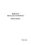
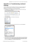
Selecting Programs
1. When a blinking underscore (or several blinking underscores) shows, you can type
a number from the numeric keypad [D].
2. When the sign "
/OK" [A] shows in the upper right corner, you can scroll through
the menu by pressing the left-arrow key [B] or the right-arrow key [C]. To select a
program, press the "OK" key [F].
Specifying Values
1. After locating a program, press the "OK" key. A blinking underscore (or
several blinking underscores) indicates which value you can change. The
value in parentheses is the default value of the menu.
2. Type a necessary value from the numeric keypad. To switch between
positive (plus) and negative (minus) values, press the [./*] (period/asterisk)
key.
3. To validate the value, press the "OK" key. To cancel the value, press the
cancel key [E].
B245/B276/B277
5-2
SM
Service Program Mode
Activating Copy Mode
You can activate the copy mode while the SP mode is running. When you do so, the copier
outputs images or patterns that help you adjust the SP-mode program.
1. Press the
key. The copy mode is activated.
2. Specify copy settings and press the "OK" key.
3. To return to the SP mode, press the
key.
You cannot end the SP mode while the copy mode is activated.
Quitting Programs/Ending (S)SP Mode
Press the
key or the "Cancel" key to quit the program. You can end the SP mode by
Service
Tables
pressing one of these keys several times.
SM
5-3
B245/B276/B277
SP Mode Tables
5.2 SP MODE TABLES
The following codes are used:
1. Asterisk (*): The settings are saved in the NVRAM. Most of them return to the
default values when you execute SP 5801 2
2. The DFU menu is for design or factory use only. You must not change the settings.
3. Brackets ([ ]): The brackets enclose the setting rage, default value, and minimum
step (with unit) as follows: [Minimum
Maximum / Default / Step].
4. SSP: The program is in the SSP Mode only. Consult your supervisor before you
use this program.
5.2.1 SP1-XXX (FEED)
1001*
Leading Edge Registration
Adjusts the printing leading-edge registration from paper trays.
1001 1 All Trays
1001 2 By-pass
[–9.0 ~ 9.0 / 0.0 / 0.1 mm/step] (
p.3-60)
1001 3 Duplex
Side-to-Side Registration
Adjusts the printing side-to-side registration from each paper feed station, using
the Trimming Area Pattern (SP 5902, No.10). Adjustments are supported for all
1002*
4 possible feed trays (including optional trays).
The SP 1002 1 setting is applied to all trays, not just the 1st tray. Settings for
trays 2 to 4 are offsets relative to the SP 1002 1 setting.
For duplex copies, the value for the front side is determined by SP 1002 1 to
4, and the value for the rear side is determined by SP 1002 6.
1002 1 1st tray
1002 2 2nd tray
1002 3 3rd tray
1002 4 4th tray
[–9.0 ~ 9.0 / 0.0 / 0.1 mm/step] (
p.3-60)
1002 5 By-pass
1002 6 Duplex
B245/B276/B277
5-4
SM
SP Mode Tables
Paper Feed Timing
1003*
Adjusts the amount of buckle the paper feed clutch applies to the paper after
the registration sensor is activated. A higher setting applies greater buckling.
1003 1 1st tray
[0 ~ 10 / 5 / 1 mm/step]
1003 2 2nd tray (B276/B277 only)
[0 ~ 10 / 5 / 1 mm/step]
1003 3 Optional tray
[0 ~ 10 / 5 / 1 mm/step]
1003 4 By-pass feed
[0 ~ 10 / 6 / 1 mm/step]
1003 5 Duplex
[0 ~ 20 / 6 / 1 mm/step]
1007
Display By-pass
1007 1 Display By-pass
Displays the by-pass paper width switch output.
Fusing Idling
This program decides the action of the Fusing Drive Release Mechanism.
1103*
When you select "1," the contact/release control is disabled and the drive
power is always transmitted to the fusing unit. As a result, the machine takes a
longer time to warm up the fusing unit. Use SP 1103 1 if fusing quality is low
1103 1 Fusing Idling
SM
Service
Tables
even when the room temperature is not very low.
[0 = No / 1 = Yes]
5-5
B245/B276/B277
SP Mode Tables
Fusing Temperature Adjustment
1105*
Adjusts the target fusing temperature. "Center" indicates the center of the roller;
"End" indicates the front and rear ends.
1105 1 Warm Up-Center
[140 ~ 180 / 160 / 1°C/step]
1105 2 Warm Up-End
1105 3 Standby-Center
[140 ~ 170 / 155 / 1°C/step]
1105 4 Standby-End
[140 ~ 165 / 150 / 1°C/step]
1105 5 Copying-Center
[140 ~ 185 / 160 / 1°C/step]
1105 6 Copying-End
1105 7 Low Level 2-Center
[0 ~ 80 / 60 / 1°C/step]
1105 8 Low Level 2-End
1105 9 Thick-Center
[140 ~ 185 / 175 / 1°C/step]
1105 10 Thick-End
1105 11 Warm Up Low-Center
[140 ~ 180 / 170 / 1°C/step]
1105 12 Warm Up Low-End
1106
Display Fusing
1106 1 Displays the fusing temperature (center)
1106 2 Displays the fusing temperature (end)
Fusing Soft Start
Adjusts the number of zero-cross cycles of the fusing lamp AC supply needed
1107*
to bring the fusing lamp power to 100% while bringing the lamp up to the
standby temperature or while copying. Increase this value if the machine is
experiencing sudden power dropouts (
p.6-61).
1107 1 Warm Up Soft Start [0 = 10 cycles / 1 = 20 cycles / 2 = 50 cycles]
1107 2 Other Soft Start
1108*
[0 = 5 cycles / 1 = 10 cycles / 2 = 20 cycles]
Set-Fusing Start
[0 = 1s / 1 = 1.5s / 2 = 2s]
1108 1 Specifies the interval for fusing-temperature control (
1109
p.6-61).
Nip Band Check
1109 1 Checks the fusing nip band (
B245/B276/B277
p.3-48).
5-6
SM
SP Mode Tables
1110*
Fan Control Timer
[30 ~ 60 / 30 / 1 s/step]
1110 1
Inputs the fan control time. The fan maintains normal speed for the specified
time after occurrence of an SC or following entry into Warm-up mode, Low
Power mode, or Night/Off mode.
1159*
Fusing Jam SC Code Setting
1159 1
1902
0=No 1=Yes
This SP mode detects SC559. Set this SP mode to ‘Yes’ if the machine
experiences paper jam problems on a continual basis.
Display-AC Freq.
Displays the fusing lamp power control frequency (as detected by the zero
1902 1 cross signal generator). The displayed value is 1/5 the actual frequency: 10 =
50 Hz, 12 = 60 Hz.
Feed Clutch Boost
Adjusts the amount of extra push that the feed clutch gives to the paper after
1903*
the skew has been corrected at registration. This feature helps the registration
Service
Tables
roller feed certain types of paper (such as thick paper). Increase the value if
thick paper is jamming after feeding from the registration roller.
1903 1 By-pass tray
[0 ~ 10 / 6 / 1 mm/step]
1903 2 2nd, 3rd, 4th tray
[0 ~ 10 / 3 / 1 mm/step]
1908*
Optional Tray Adj.
Adjusts the reverse time for the upper and lower paper lift motors.
1908 1 1st optional
[–2 ~ +2 / 0 / 1/step]
1908 2 2nd optional
(
1911*
p.7-12)
By-pass Envelope
[0 = Disabled / 1= Enabled
The program dedicated to envelope printing runs when you enable this
1911 1 program (SP 1911 1) and you select "Thick Paper" as the paper type of the
by-pass tray (System Settings > Tray Paper Settings > Paper Type: Bypass
Tray).
SM
5-7
B245/B276/B277
SP Mode Tables
5.2.2 SP2-XXX (DRUM)
2001*
Charge Roller Bias Adjustment
Printing
[–2100 ~ –1500 / –1700 / 1 V/step]
Adjusts the voltage applied to the charge roller when printing. The actually
2001 1 applied voltage changes automatically as charge roller voltage correction is
carried out. The value you set here becomes the base value on which this
correction is carried out.
ID sensor pattern
2001 2
[0 ~ 400 / 300 / 1 V/step]
Adjusts the voltage applied to the charge roller when generating the Vsdp ID
sensor pattern (as part of charge roller voltage correction). The actual
charge-roller voltage is obtained by adding this value to the value of SP 2001 1.
2101*
2101 1
Erase Margin Adjustment
Leading edge
[0.0 ~ 9.0 / 2.0 / 0.1 mm/step] (
p.3-60)
Specification: 2 ± 1.5 mm
Adjusts the leading edge erase margin.
Trailing
2101 2
[0.0 ~ 9.0 / 3.0 / 0.1 mm/step] (
p.3-60)
Specification: 2 +2.5/–1.5 mm
Adjusts the trailing edge erase margin. The rear trailing edge is this value plus
1.2 mm.
2101 3
Left side
[0.0 ~ 9.0 / 2.0 / 0.1 mm/step] (
p.3-60)
Specification: 2 ± 1.5 mm
Adjusts the left edge erase margin. The rear left edge is this value plus 0.3 mm.
Right side
2101 4
[0.0 ~ 9.0 / 2.0 / 0.1 mm/step] (
p.3-60)
Specification: 2 +2.5/–1.5 mm
Adjusts the right edge erase margin. The rear right edge is this value plus 0.3
mm.
B245/B276/B277
5-8
SM
SP Mode Tables
2201*
Development Bias Adjustment
Printing
2201 1
[–1500 ~ –200 / –650 / 1 V/step]
Adjusts the voltage applied to the development roller when printing. This can
be adjusted as a temporary measure if faint copies are being produced due to
an aging drum.
ID sensor pattern
2201 2
[–2 = LL (220 V) / -1 = L (260 V) / 0 = N (300 V) /
1 = H (340 V) / 2 = HH (380 V)]
Adjusts the voltage applied to the development roller when generating the ID
sensor pattern. The actual voltage applied is this setting plus the value of SP
2201 1. The setting affects ID sensor pattern density, which in turn affects the
toner supply.
2213*
Outputs after Near End
[0 = 50 pages / 1 = 20 pages]
2213 1
Sets the number of copy/print pages that can be made after toner near-end has
been detected. Reduce the number of pages if the user normally makes copies
2214
Developer Initialization
2214 1
2220
Initializes both the TD sensor toner supply target voltage and the TD sensor
gain value. Carry this out after replacing the developer or the TD sensor.
TD Sensor Output Value Display
Displays:
1. Vt: the current TD sensor output value and
2220 1
2. Vref: the target TD output value Vts (SP 2926) + correction for
ID sensor output.
The TD sensor output value changes every copy. If 1 > 2, toner is supplied to
the development unit.
SM
5-9
B245/B276/B277
Service
Tables
with a high image ratio.
SP Mode Tables
2221
ID Sensor Error Analysis
2221 1 Vsg
Displays the Vsg value.
2221 2 Vsp
Displays the Vsp value.
2221 3 PWM
Displays the PWM value.
2221 4 Vsdp
Displays the Vsdp value.
2221 5 Vt
Displays the Vt value.
2221 6 Vts
Displays the Vts value.
2301*
Transfer Current Adjustment
Normal paper
[–2 = –4 mA / –1 = –2 mA / 0 = 0 mA / 1 = 2 mA /
2 = +4 mA]
2301 1 Adjusts the current applied to the transfer roller when feeding from a paper tray.
Use a high setting if the user normally feeds relatively thick paper (within spec)
from a paper tray (
Thick/Special paper
2301 2
p.6-55).
[–2 = –4 mA / –1 = –2 mA / 0 = 0 mA / 1 = 2 mA /
2 = +4 mA]
Adjusts the current applied to the transfer roller when feeding from the by-pass
tray. Use a high setting (a) if the user normally feeds relatively thick paper from
the by-pass tray, or (b) if waste toner is re-attracted from the drum (which can
occur when using transparencies). (
Duplex
p.6-55)
[–2 = –4 mA / –1 = –2 mA / 0 = 0 mA / 1 = 2 mA
/ 2 = +4 mA]
2301 3 Adjusts the current applied to the transfer roller when carrying out a duplex job.
Use this SP if there is poor image transfer on the rear side of duplex copies
(
p.6-55).
Cleaning
2301 4
[–10 ~ 0 / –1 / 1 mA/step]
Adjusts the current applied to the transfer roller for roller cleaning. Increase the
current if toner remains on the roller after cleaning. (Remaining toner may
cause dirty background on the rear side.) (
B245/B276/B277
5-10
p.6-55)
SM
SP Mode Tables
2802
Forced Developer Churning
Initializes the developer and checks the TD sensor output (Vt). The machine
mixes the developer for 2 minutes while reading and displaying the Vt value.
2802 1
The machine does not initialize the TD sensor output. If the machine has not
been used for a long period of time, prints may have a dirty background. In this
case, use this SP mode to mix the developer. The message "Completed" is
displayed when the program ends normally.
2906*
Tailing Correction
Shift value
[0.0 ~ 1.0 / 0.0 / 0.1 mm/step]
Shifts the image writing position in intervals specified by SP 2906 2. When
2906 1
making many copies of an original that contains vertical lines (such as in
tables), the paper may not separate correctly. This can cause tailing images
(ghosts of the vertical lines continuing past the bottom of the table). This SP
can be used to prevent this.
2906 2
Interval
[1 ~ 10 / 1 / 1 page/step]
2908
Forced Toner Supply
Forces the toner bottle to supply toner to the toner supply unit. Press “1” to
2908 1
start. The machine continues to supply toner until the toner concentration in the
development unit reaches the standard level, or for up to 2 minutes (whichever
comes first).
2915*
Polygon Mirror Motor Idling Time
[0 = None / 1 = 15 s / 2 = 25 s]
Selects the polygon mirror motor idling time. To increase the speed of the first
copy, the mirror motor begins idling when the user sets an original, touches a
2915 1 key, or opens the platen cover or DF. If this setting is left at the default (15 s),
the motor will stop if the user does nothing for 15s. If the setting is “0”, the
motor will not switch off during standby. (But note that regardless of the setting,
the motor will switch off when the machine enters energy saver mode.)
SM
5-11
B245/B276/B277
Service
Tables
Changes the interval for the image shift specified by SP 2906 1.
SP Mode Tables
2921*
Toner Supply Mode
[0 = Sensor 1 / 1 = Sensor 2 (DFU) / 2 = Fixed 1 (DFU) / 3 = Fixed 2]
2921 1
Selects the toner supply mode. Under normal conditions this should be set to
“0”. You can temporarily change this to “3” if the TD sensor is defective. Do not
set to “1” or “2”, as these are for design use only (
2922*
p.6-39).
Toner Supply Time
[0.1 ~ 5.0 / 0.4 / 0.1 s/step]
Adjusts the toner supply motor ON time for Sensor 1 and Sensor 2 toner supply
2922 1
mode. Accordingly, this setting is effective only if SP 2921 is set to “0” or “1”
Raising this value increases the toner supply motor ON time. Set to a high
value if the user tends to make many copies having high proportions of solid
black image areas (
2923*
p.6-39).
Toner Recovery Time
[3 ~ 60 / 30 / 1 s/step]
Adjusts the toner supply motor ON time used during toner recovery from Toner
2923 1 Near End or Toner End. This setting is effective only if SP 2921 is set to “0”
Since toner recovery is carried out in 3-second cycles, the input value should
be a multiple of 3 (3, 6, 9...). (
2925*
p.6-39)
Toner Supply Rate
Adjusts the toner supply time for fixed toner supply mode. This setting is
effective only if SP 2921 is set to “2” or “3”.[0 ~ 7 / 0]t = 200ms, and settings are
as follows
2925 1
0 = t , 1 = 2t, 2 = 4t, 3 = 8t, 4 = 12t, 5 = 16t,
6 = on continuously, 7 = 0 s
Raising this value increases the toner supply motor ON time. Set to a high
value if the user tends to make many copies having high proportions of solid
black image areas (
B245/B276/B277
p.6-39).
5-12
SM
SP Mode Tables
2926*
Standard Vt
[0.00 ~ 5.00 / 2.50 / 0.01 V/step] DFU
2926 1
Adjusts Vts (the Vt value for new developer). The TD sensor output is adjusted
to this value during the TD sensor initial setting process]. This SP is effective
only when SP 2921 is “0”, “1”, or “2”.
2927*
ID Sensor Control
[0 = No / 1 = Yes]
2927 1
Selects whether the ID sensor is or is not used for toner density control. This
value should normally be left at “1”. If the value is “0”, dirty background may
occur after long periods of non-use.
2928
Toner End Clear
Clears the toner end condition without adding new toner. The following are
cleared:
1. Toner end indicator (goes out)·
2. Toner near-end counter
3. Toner near-end level
This function should generally not be used. If you clear the toner end condition
without adding new toner, there is a risk that the drum may eventually begin to
attract carrier after many more copies are made and toner runs out. This
attracted carrier may damage the drum.
2929*
Vref Limits
Adjust the upper or lower Vref limit.
2929 1 Upper
[0.50 ~ 3.50 / 3.20 / 0.01V/step] DFU
2929 2 Lower
[0.50 ~ 3.50 / 0.70 / 0.01V/step] DFU
2994*
ID Sensor Detection Temperature [30 ~ 90 / 30 / 1 C/step]
While the machine is recovering from an energy saver mode, or while the
2994 1 machine starts, the controller ignores the ID-sensor signals if the fusing
temperature is at the specified value or higher.
SM
5-13
B245/B276/B277
Service
Tables
2928 1
SP Mode Tables
2996*
Transfer Roller Cleaning
Selects whether the transfer roller is cleaned before each copy job. Set this to
2996 1
“1” if dirty background is appearing on the reverse side of the first page of copy
jobs. Note that this will increase the time required to generate the first copy. If
the setting is “0”, the transfer roller is never cleaned (
2997*
2998*
2998 1
Toner Density Sensor Standard
Voltage
Main Scan Magnification
p.6-56).
[0 / 2.5 / 5/ 0.01V/step] DFU
[–0.5 ~ +0.5 / 0.0 / 0.1%/step]
Adjusts the magnification along the main scan direction, for all print modes
(copy, printing). The specification is 100 ± 1.0% (
B245/B276/B277
5-14
p.3-60).
SM
SP Mode Tables
5.2.3 SP4-XXX (SCANNER)
4008*
4008 1
4009*
Sub-Scan Magnification (Scanner)
[-0.9 ~ +0.9 / 0.0 / 0.1%/step]
Adjusts the actual sub-scan direction scanning magnification. The higher the
setting, the lower the scanner motor speed (
Main Scan Magnification (Scanner)
p.3-60).
[–0.9 ~ +0.9 / 0.0 / 0.1%/step]
Adjusts the magnification along the main scan direction, for scanning.
4009 1
The specification is 100 ± 1.0%
Main scan magnification is implemented in steps of 0.5. Accordingly, your input
value should be a multiple of 0.5 (–1.0, –0.5, 0, +0.5, or +1.0)
4010*
Leading Edge Registration (Scanner)
[–5.0 ~ +5.0 / 0.0 / 0.1 mm/step]
Adjusts the leading edge registration for scanning in platen mode (
p.3-60).
4010 1 (–): The image moves toward the leading edge.
(+): The image moves toward the trailing edge·
4011*
Side-to-side Registration (Scanner) [–4.2 ~ +4.2 / 0.0 / 0.1 mm/step]
Adjusts the side-to-side registration for scanning in platen mode (
p.3-60
4011 1 Increasing the value shifts the image to the right
The specification is 2 ± 1.5 mm.
Scan Erase Margin
4012*
Adjusts the scanning margin individually for each of the four edges. It is
generally best to adjust the scanning margin as little as possible, and use the
printing margin for image adjustments.
4012 1 Leading edge
4012 2 Trailing edge
4012 3 Left
[0 ~ 9.0 / 1.0 / 0.1 mm/step]
4012 4 Right
SM
5-15
B245/B276/B277
Service
Tables
The specification is 2 ± 1.5 mm.
SP Mode Tables
4013
Scanner Free Run
4013 1
4015*
Performs a scanner free run with the exposure lamp on. Press ON or to start.
Press OFF to stop.
White Plate Scanning
Start position
4015 1
[–3.0 ~ +6.0 / 0.0 / 0.1 mm/step]
Adjusts the scanning start position on the white plate for auto shading. The
base value stored in the machine is 15.2 mm toward the white plate from the
scanner HP. This SP setting specifies the offset from this base value.
Scanning length
[–3.0 ~ +6.0 / 0.0 / 0.1 mm/step]
Adjusts the length of the white plate scan, in the main scan direction. The scan
4015 2 begins at the start position set above [in SP 4015 1] and extends for the
specified length. The base value stored in the machine is 4.76 mm. This SP
setting specifies the offset from this base value.
4301
Display-APS Data
4301 1
4303*
Displays the status of the APS sensors and platen/DF cover sensor (
p.5-53).
APS Small Size Original
[0 = No (not detected) / 1 = Yes (A5/HLT LEF)]
Selects whether or not the copier will consider the original to be A5/HLT LEF
4303 1
when the APS sensors cannot detect its size. If “Yes” is selected, paper sizes
that cannot be detected by the APS sensors are regarded as A5/HLT LEF. If
“No" is selected, “Cannot detect original size” will be displayed.
B245/B276/B277
5-16
SM
SP Mode Tables
4305*
APS Priority
[0 = Normal / 1 = A4/LT / 2 = 8K/16K]
1. A4/LT
1. North America model: When the ASP detects the LT size, the
controller interprets it as the A4 size.
2. Other models: When the ASP detects the A4 size, the controller
interprets it as the LT size. 2. 8K/16K (for the China model only)
3. When the ASP detects the A3/B4 SEF, the controller interprets it as the
8K SEF.
4. When the ASP detects the B5/A4 SEF, the controller interprets it as the
16K SEF.
4305 1
5. When the ASP detects the B5/A4 LEF, the controller interprets it as the
16K LEF.
The Europe model interprets undetected original sizes as A5 LEF under the
following conditions:
1. SP 4303 1 is "Yes," and
2. SP 4305 1 is "Normal"
The Europe model interprets undetected original sizes as LT SEF under the
following conditions:
Service
Tables
1. SP 4303 1 is "Yes," and
2. SP 4305 1 is "A4/LT"
4428
Scan Auto-Adjustment
4428 1
SM
Performs the automatic scanner adjustment. Use this SP mode after replacing
the white plate.
5-17
B245/B276/B277
SP Mode Tables
4901
SBU White Level Adjustment
Black Display-Error
[0 = Normal / 1 = Error]
4901 1 Displays the return code of the black-level adjustment. When an error is
detected, SC143 or SC145 is generated.
Black Feedback-EVEN
4901 2
[0 8191]
Displays the feedback value of the even channels given by the SBU. Normally,
the value is 1, 2, 3, ..., 8188, 8189, or 8190. However, machine may operate
normally even when the value is 0 or 8191.
Black Feedback-ODD
4901 3
[0 8191]
Displays the feedback value of the odd channels given by the SBU. Normally,
the value is 1, 2, 3, ..., 8188, 8189, or 8190. However, machine may operate
normally even when the value is 0 or 8191.
Black Display-Target
4901 4
[0 63 / 10 /step]
Displays the target value for the black-level adjustment executed during
machine initialization. Normally, the value is 10. Other values indicate that the
adjustment has ended unsuccessfully.
4901 5*
White Target
[0 511 / 511 / 1/step]
Displays the target value for the white-level adjustment.
4901 6
White Result
[0 511 / 0 / 1/step]
Displays the result of the white-level adjustment.
White Display-Error
[0 = Normal / 1 = Error]
4901 8 Displays the return code of the white-level adjustment. When an error is
detected, SC143 is generated.
White Display-Overflow
[0 = Normal / 1 = Error]
4901 9 Displays a return code of the white-level adjustment. The code "1" (error) is
returned if the adjustment result is not in the range of the values in SP 4901 6.
B245/B276/B277
5-18
SM
SP Mode Tables
White Number of Attempt
[0 20 / 0 / 1/step]
Displays how many times the white-level adjustment is retried. The value does
not include the first execution of the white adjustment. For example, if the value
is "2", this indicates that the white-level adjustment has been executed three
4901 10 times. The white-level adjustment can be executed 20 times or less. Therefore,
if the value is "20," this indicates that the white-level adjustment has ended
abnormally (as described, the value "20" does not include the first execution). If
the white-level adjustment is unsuccessful, the machine uses the result of the
latest, successful white-level adjustment.
Auto Adjustment Setting
[222 281 / 256 / 1/step]
4901 11 Displays the parameter of the white-level adjustment. The value is based on the
result of SP 4901 12.
Auto Adjustment-Result
4901 12
[0 600 / 0 / 1/step]
Displays the result of the white-level adjustment. Normally, the value is between
228 and 281 (including the both values). When the value is normal, it is stored
as the value of SP 4901 11.
Auto Adjustment-Error
Displays a return code of the white-level adjustment. The code "1" (error) is
returned if the adjustment result value is less than 228 or larger than 281 (
SP490 12).
4902*
4902 1
4903*
Exposure Lamp ON
Turns the exposure lamp on or off. To turn off the exposure lamp, select “OFF”.
(The exposure lamp shuts off automatically after 180 seconds.)
ADS Level
[0 255 / 252 / 1/step]
4903 1 Adjusts the ADS level.
4904*
ADS Lower Limit
[0 255 / 80 / 1/step]
4904 1 Adjusts the ADS lower limit.
SM
5-19
B245/B276/B277
Service
Tables
4901 14
[0 = Normal / 1 = Error]
SP Mode Tables
4905*
ADS Level
4905 1
4921*
[0 = All / 1 = One]
Checks the whole area (0 = All) or the area between 15 mm and 90 mm from
the left edge (1 = One) to adjust the ADS level.
Image Adj Selection
Image Adj Selection (Copy)
4921 1
[0 ~ 10 / 0 / 1]
Selects which mode the settings from SP 4922 to SP 4932 and are used for:
0 = None, 1 = Text 1, 2 =Text 2, 3= Photo 1, 4 = Photo 2, 5 = Photo 3, 6 =
Special 1, 7 = Special 2, 8 = Special 3, 9 = Special 4, 10 = Special 5
Scanner Gamma
4922*
Selects “text” or “photo” as the priority output mode. This setting is applied to all
image processing modes of SP 4921.
4922 1 Scanner Gamma (Copy)
[0=System default/1=Text/2=Photo]
4922 3
Notch Selection
Selects the value of the center ID adjustment notch for the ID adjustment LEDs.
4923*
Normally the center notch is 3 (range 1-5). If –1 is selected, each notch shifts
down (becomes lighter). If +1 is selected, each notch shifts up (becomes
darker).·
This setting is applied to all image processing modes of SP 4921.
4923 1 Notch Selection (Copy)
B245/B276/B277
[–1 = Light / 0 = Normal / +1 = Dark]
5-20
SM
SP Mode Tables
Texture Removal
Adjusts the texture removal level that is used with error diffusion. 0: The default
value for each mode is used. Text 1, Photo 2, Special 2, and Special 5 have a
4926*
default of 3 and Photo 1, 3 have a default of 1.
1: No removal applied.
2 – 5: Removal applied at the level specified here. The higher the setting
(level), the less clear the image will become (more texture removal). This
setting is only applied to the originals in SP 4921.
4926 1 Texture Removal (Copy)
[0 ~ 6 / 1/step]
4926 3 Texture Removal (Scanner) [0 ~ 6 / 1/step]
Line Width Correction
4927*
Adjusts the line width correction algorithm. Positive settings produce thicker
lines; negative settings produce thinner lines. This setting is only applied to the
originals in SP 4921.
4927 1 Line Width Correction (Copy)
[–2 ~ 2 / 0 / 1/step]
Independent Dot Erase
4928*
Selects the dot erase level. Higher settings provide greater erasure. This
setting is only applied to the originals in SP 4921.
4928 1 Independent Dot Erase (Copy)
[–2 ~ 2 / 0 / 1/step]
4928 3 Independent Dot Erase (Scanner) [–2 ~ 2 / 0 / 1/step]
4929*
Positive/Negative
[0 = No, 1 = Yes]
Inverts white and black. This setting is only applied to the originals in SP 4921.
4929 1 Positive/Negative (Copy)
4930*
Sharpness-Edge
[–2 ~ 2 / 0 / 1/step]
Adjust the clarity. This setting is only applied to the originals in SP 4921.
4930 1 Sharpness-Edge (Copy)
4930 3 Sharpness-Edge (Scanner)
SM
5-21
B245/B276/B277
Service
Tables
4927 3 Line Width Correction (Scanner) [–2 ~ 2 / 0 / 1/step]
SP Mode Tables
4931*
Sharpness-Solid
[–2 ~ 2 / 0 / 1/step]
Adjust the clarity. This setting is only applied to the originals in SP 4921.
4931 1 Sharpness-Solid (Copy)
4931 3 Sharpness-Solid (Scanner)
4932*
Sharpness-Low ID
[–2 ~ 2 / 0 / 1/step]
Adjust the clarity. This setting is only applied to the originals in SP 4921.
4932 1 Sharpness- Low ID (Copy)
4941*
White Line Erase
[0 ~ 2 / 1 / 1/step]
Selects the white line erase level.
0: None, 1: Weak, 2: Strong
4941 1 This setting is effective only Photo 1, Photo 3, Special 3 or Special 4 mode.
0: White line erase is not used, and white level
correction is used instead·
This setting is applied regardless of what mode has been selected in SP 4921.
4942*
Black Line Erase
[0 ~ 3 / 2 / 1/step]
Selects the black line erase level. This setting is effective only when originals
4942 1
are scanned by the A(R)DF.
[0 = No / 1 = Very weak / 2 = Weak / 3 = Strong]
This setting is applied regardless of what mode has been selected in SP 4921.
B245/B276/B277
5-22
SM
SP Mode Tables
5.2.4 SP5-XXX (MODE)
5001
All Indicators On
All LEDs turn on. The LCD turns on or off every 3 seconds. Press the reset key
5001 1
5045*
to end this program.
[Accounting count]
[0 to 1 / 1 / -]
0: Developments, 1: Pages
5045 1 Selects the counting method to either developments or prints.
5104*
A3/DLT Double Count
[0 = Enabled / 1 = Disabled /
2 = Disabled if the size is undetected]
Selects whether the machine counts twice for each sheet of A3/11"x 17". If this
5104 1 is set to “Yes” is selected, the total (mechanical) counter and the current user
counter will both increment by two for each A3/11" x 17" sheet.
0: None
Optional Counter Type
11: MF key card (Increment)
12: MF key card (Decrement)
5113 1 Selects the corresponding key for installed devices such as coin lock.
5120*
Clr-OP Count Remv
[0=Yes / 1=Standby only / 2=No]
Determines under which conditions the copy job settings are reset when the
key counter is removed. With 0, the settings are cleared if the counter is
5120 1
removed at the end of a job or midway through a job. With 1, they are only
cleared if the counter is removed at the end of a job. With 2, they are not
cleared at all, under either condition. With duplex copies, the job settings are
always preserved, regardless of the setting of this SP mode.
5121*
5121 1
SM
Count Up Timing
[0 = Feed In / 1 = Exit]
Selects whether the key counter increments at time of paper feed-in or at time
of paper exit.
5-23
B245/B276/B277
Service
Tables
5113*
SP Mode Tables
5127*
APS Mode
[0 = Enabled / 1 = Disabled]
5127 1 Enables or disables the APS mode..
5501*
PM Alarm Interval (Printout) [0 ~ 9999 / 0 / 0K copies/step]
5501 1 Specifies when the PM alarm occurs.
5801
Memory Clear
5801 2 Engine (
B245/B276/B277
p.5-37)
5-24
SM
SP Mode Tables
5802
Machine Free Run
5802 1
5803
Starts a free run of both the scanner and the printer. Press "ON" to start; press
"OFF" to stop.
Input Check
(
5804
p.5-39)
Output Check
p.5-42)
Service
Tables
(
SM
5-25
B245/B276/B277
SP Mode Tables
5807*
Rev 05/2007
Area Selection
Selects the display language group.
5807 1
1 = Japan, 2 = North America, 3 = Europe, 4 = Taiwan, 5 = Asia,
6 = China, 7 = Korea
SP 5807 1 is not cleared by SP 5801 2 (
5811*
p.5-37).
Serial Num Input
5811 1 Setting
Sets the machine serial number. FA
5811 3 ID 2 Code Display
Displays the ID 2 Code (used for NRS
5812*
Service TEL
Service TEL (Telephone)
5812 1
Use this to input the telephone number of the service representative. (The
number is displayed when a service call condition occurs.) To input a dash,
press . To delete the current telephone number, press .
Service TEL (Facsimile)
5812 2 Use this to input the fax number printed on user counter reports. To input a
dash, press
5824
NVRAM Upload
5824 1 (
5825
p.5-44)
NVRAM Download
5825 1 (
5827
. To delete the current fax number, press .
p.5-44)
Program Download
5827 1 Downloads programs to the machine
B245/B276/B277
5-26
SM
SP Mode Tables
5901
Printer Free Run
5901 1 Executes the free run. Press "ON" to start; press "OFF" to stop.
5902
Test Pattern Print
5902 1 (
5907*
p.5-49)
Plug & Play Setting
Selects the brand name and production name for the Plug and Play function.
These names are registered in the NVRAM. If the NVRAM becomes defective,
5907 1
these names should be re-registered. Use the right-arrow or left-arrow key to
scroll through the list of brand names. To select a brand name, press the OK
key. An asterisk (*) indicates which manufacture is currently selected. (
p.5-37)
A3/DLT Counter Display
5918 1
5990
[0 = Off / 1 = On]
Sets the key press display for the counter key. This setting has no relation to
(SSP) SP5-104 A3/DLT Double Count.
Service
Tables
5918*
SMC Print
5990 1 All
5990 2 SP
5990 3 User Program
p.5-52)
(
5990 4 Logging Data
5990 5 Big font
5993
DFU
5993 1
5998
Memory Clear
5998 1 Memory Clear
SM
5-27
B245/B276/B277
SP Mode Tables
5.2.5 SP6-XXX (PERIPHERALS)
6006*
ADF Adjustment (
p.3-64
NOTE: Available menus depend on the machine model and its configuration.
ADF Adjustment (StoS/Front Regist) [–5.0 ~ +5.0 / 0.0 / 0.1 mm/step]
6006 1 Adjusts the side-to-side registration for the front side of the original, for ADF
mode. Use the
key to select “+” or “–” before entering the value
ADF Adjustment (Leading Regist)
[–5.0 ~ +5.0 / 0.0 / 0.1 mm/step]
6006 2 Adjusts the leading edge registration for ADF mode. Use the
key to select
“+” or “–” before entering the value.
ADF Adjustment (Trailing Erase)
[–3.0 ~ +3.0 / –1.0 / 0.1 mm/step]
6006 3 Adjusts the trailing edge erase margin for ADF mode. Use the
key to select
“+” or “–” before entering the value.
ADF Adjustment (StoS/Rear Regist) [–5.0 ~ +5.0 / 0.0 / 0.5 mm/step]
6006 4 Adjusts the side-to-side registration for the rear side of duplex originals, for ADF
mode. Use the
6006 5
key to select “+” or “–” before entering the value.
ADF Adjustment (Sub-scan Magnif) [–0.9 ~ +0.9 / 0.0 / 0.1 %/step]
Adjust the sub-scan magnification for the ADF.
ADF Adjustment (Original Curl Adj) [0 = No / 1 = Yes]
6006 6
Enables or disables the skew adjustment for the reverse sides of originals.
When you enable SP6-006-6, adjust the distance of the skew adjustment (SP
6006 7).
ADF Adjustment (Skew Correction) [–20 ~ +20 / 0 / 1 mm/step]
6006 7 Specifies the distance of the skew adjustment. SP 6006 7 is effective when you
enable SP 6006 6 (ADF Adjustment [Original Curl Adj]).
6009
ADF Free Run
6009 1 Performs an ADF free run. Press "ON" to start; press "OFF" to stop.
6010
Stamp Position Adjustment
[–10 ~ +10 / 0 / 1 mm/step]
6010 1 Adjusts the stamp position in the sub-scan direction. for the fax mode.
6901
Display ADF/APS
6901 1 Displays the status of the ADF original size sensors (
B245/B276/B277
5-28
p.5-53).
SM
SP Mode Tables
6910*
ADF Shading Time
[0 ~ 60 / 10 / 1 s/step]
Adjusts the interval used for the shading processing in the ADF mode. Light
6910 1 and heat in the room may affect the scanner response. Reduce this setting if
Service
Tables
copy quality indicates that the white level is drifting during ADF copy jobs.
SM
5-29
B245/B276/B277
SP Mode Tables
5.2.6 SP7-XXX (DATA LOG)
7001*
Total Operation
7001 1 Shows the total operation time (total drum rotation time).
7401*
Counter–SC Total
[0 ~ 9999 / 0 / 1/step]
7401 1 Shows how many times SC codes are generated.
7403*
SC History
7403 1 Shows the histories of the latest 10 SC codes.
7502*
Counter–Paper Jam
[0 ~ 9999 / 0 / 1/step]
7502 1 Shows the total number of copy paper jams.
7503*
Counter–Orgn Jam
[0 ~ 9999 / 0 / 1/step]
7503 1 Shows the total number of original jams,
Counter-Each P Jam
7504*
[0 ~ 9999 / 0 / 1/step]
Displays the total number of the paper jams classified by timing and location.
7504 1
Counter-Each P Jam (At power on)
Paper jam occurs at power on.
7504 10
Counter-Each P Jam (Off-Regist NoFeed)
Paper does not reach the registration sensor (from a paper tray).
7504 11
Counter-Each P Jam (Off-1 Vertical SN)
Paper does not reach the relay sensor.
7504 12
Counter-Each P Jam (On-1 Vertical SN)
Paper is caught at the relay sensor.
7504 21
Counter-Each P Jam (Off-2 Vertical SN)
Paper does not reach the vertical transport sensor.
7504 22
Counter-Each P Jam (On-2 Vertical SN)
Paper is caught at the vertical transport sensor.
B245/B276/B277
5-30
SM
SP Mode Tables
Counter Each P Jam (Off-3 Vertical SN)
7504 31 Paper does not reach the vertical transport sensor in the optional paper feed
unit.
Counter Each P Jam (On-3 Vertical SN)
7504 32 Paper is caught at the vertical transport sensor in the optional paper feed
unit.
7504 50
Counter-Each P Jam (Off-Regist Bypass)
Paper does not reach the registration sensor (from the by-pass tray).
Counter-Each P Jam (Off-Regist Duplex)
7504 60 Paper does not reach the registration sensor during reverse-side printing (for
duplex printing).
7504 70
Counter-Each P Jam (On-Regist SN)
Paper is caught at the registration sensor.
7504 120
Counter-Each P Jam (On-Exit SN)
Paper is caught at the exit sensor (previous page).
7504 121
Counter-Each P Jam (Off-Exit SN)
Paper does not reach the exit sensor.
Counter-Each P Jam (On-Exit SN)
Service
Tables
7504 122
Paper is caught at the exit sensor.
7504 123
Counter-Each P Jam (Off-Dup Inverter)
Paper does not reach the duplex inverter sensor (from the registration roller).
7504 125
Counter-Each P Jam (On-Dup Inverter)
Paper is caught at the duplex inverter sensor.
7504 126
Counter-Each P Jam (Off-Dup Entrance)
Paper does not reach the duplex entrance sensor.
7504 127
Counter-Each P Jam (Off-Dup Entrance)
Paper is caught at the duplex entrance sensor.
7504 128
Counter-Each P Jam (Off-Duplex Exit)
Paper does not reach the duplex exit sensor.
7504 129
Counter-Each P Jam (On-Duplex Exit)
Paper is caught at the duplex exit sensor.
SM
5-31
B245/B276/B277
SP Mode Tables
7504 130
Counter-Each P Jam (Off-1 bin Exit SN)
Paper does not reach the one-bin tray.
7504 131
Counter-Each P Jam (On-1 bin Exit SN)
Paper is caught at the one-bin tray.
Counter-Each O Jam
7505*
[0 ~ 9999 / 0 / 1/step]
Displays the total number of the original jams on the ADF that have occurred
at a certain timing or at a certain location.
7505 210
Counter-Each O Jam (Off-Regist SN)
The original does not reach the registration sensor.
7505 211
Counter-Each O Jam (On-Regist SN)
The original is caught at the registration sensor.
7505 212
Counter-Each O Jam (Off-Relay SN)
The original does not reach the exit sensor.
7505 213
Counter-Each O Jam (On-Relay SN)
The original is caught at the exit sensor.
7505 214
Counter-Each O Jam (Off-Inverter SN)
The original does not reach the reverse sensor.
7505 215
Counter-Each O Jam (On Inverter SN)
The original is caught at the reverse sensor.
Counter-Each O Jam (Insufficient gap)
7505 216 The distance between originals is not sufficient. This jam can occur when the
original is not of the standard size.
7507*
Dsply-P Jam Hist
Displays the latest 10 paper-jam history. The list below shows the possible 22
codes:
7507 1
1, 10, 11, 12, 21, 22, 31, 32, 50, 60, 70, 120, 121, 122, 123, 125, 126, 127, 128,
129, 130, 131
The codes correspond to the menus of SP 7504. For example, the code 1
corresponds to SP 7504 1, and the code 10 corresponds to SP 7504 10.
B245/B276/B277
5-32
SM
SP Mode Tables
7508*
Dsply-O Jam Hist
Displays the total number of the original-jams history. The following are the
possible seven codes:
7508 1 210, 211, 212, 213, 214, 215, 216
The codes correspond to the menus of SP 7505. For example, the code 210
corresponds to SP 7505 210, and the code 211 corresponds to SP 7505 211.
7801
Memory/Version/PN
7801 2
Memory/Version (BICU)
Displays the version of the BICU board
7801 5
Memory/Version (ADF)
Displays the P/N and suffix of the ADF ROM.
7801 15
Memory/Version (Printer/Scanner)
Displays the P/N and suffix of the Printer/Scanner ROM.
7803*
Display–PM Count
7804
Reset–PM Counter
7804 1
7807
Resets the PM counter (SP 7803 1). When the program ends normally, the
message "Completed" is displayed.
Reset–SC/Jam Counters
Resets the SC, paper, original, and total jam counters. When the program ends
7807 1
normally, the message "Completed" is displayed. SP 7807 1 does not reset the
following logs: SP 7507 (Display-Paper Jam History) and SP 7508
(Display-Original Jam History).
7808
Reset–Counters
Resets all counters except for the management counters. The management
7808 1
counters are the counters that are not changed by NVRAM Download (SP 5825
1) When the program ends normally, the message the message "Completed" is
displayed.
SM
5-33
B245/B276/B277
Service
Tables
7803 1 Displays the PM counter.
SP Mode Tables
7810
Reset–Key Op Code
Resets the key operator code. Use SP 7810 1 when the customer has forgotten
the key-operator code. When the program ends normally, the message
7810 1
"Completed" is displayed, if the program ends abnormally, an error message is
displayed. If the customer forgets the key operator code. To specify a new
key-operator code, use the User Tools: System Settings
Key Operator Code
7832*
7832 1
On
Key Operator Tools
Enter Key Operator Code.
Display-Self-Diag
Displays the SC codes and the number of their occurrences. Each number is in
the range of 0 to 9999.
Dsply–Info Count
7991*
Displays the total operating time or the total number of operations. The time is
displayed in the following format: day:hour:minute:second.
Dsply–Info Count (Dsply-Timer Count)
7991 1 The total of the time when the main switch is kept on (excluding the time when
the safety switch is off (
7991 2
p.6-29).
Dsply–Info Count (Dsply-APS Working)
The total of the time when the APS is working.
7991 3
Dsply-Info Count (Dsply-ID S Work)
The total of the time when the ID sensor is working.
7991 4
Dsply-Info Count (Dsply-Dev Counter)
The total number of paper outputs.
7991 5
Dsply-Info Count (Dsply-ID Er Count)
The total number of ID-sensor errors.
7992*
7992 1
Reset–Info Count
Reset–Info Count (Reset-Timer Count)
Clears the counter of SP 7991 1.
7992 5
Reset-Info Count (Reset-ID Er Count)
Clears the counter of SP 7991 5.
B245/B276/B277
5-34
SM
SP Mode Tables
5.2.7 SP8-XXX (HISTORY)
8191 1
8192*
8192 1
8195*
8195 1
8201
T: Total Scan PGS
Displays the total number of scanned pages. Both sides are counted when the
front and reverse sides of an original (fed from the ADF) are scanned.
C: Total Scan PGS
front and reverse sides of an original (fed from the ADF) are scanned.
S: Total Scan PGS
the front and reverse sides of an original (fed from the ADF) are scanned.
8221*
8221 1
[0 9999999 / 0 / 1 sheet/step]
Displays the total number of scanned originals (by copying jobs and scanning
jobs) classified by paper size. The following size is counted: A3/DLT and larger.
(A3/DLT, Larger)
8205 1
[0 9999999 / 0 / 1 sheet/step]
Displays the total number of scanned originals. Both sides are counted when
S: L Size Scan PGS
8205
[0 9999999 / 0 / 1 sheet/step]
Displays the total number of scanned copies. Both sides are counted when the
T: L Size Scan PGS
8201 1
[0 9999999 / 0 / 1 sheet/step]
Service
Tables
8191*
[0 9999999 / 0 / 1 sheet/step]
Displays the total number of scanned originals (by scanning jobs) classified by
paper size. The following size is counted: A3/DLT and larger.
ADF Org Feed
[0 9999999 / 0 / 1 sheet/step]
ADF Org Feed (Front)
Displays the total number of scanned front sides of originals fed from the ADF.
ADF Org Feed (Back)
8221 2 Displays the total number of scanned reverse sides of originals fed from the
ADF.
8291*
T: Scan PGS/TWAIN
[0 9999999 / 0 / 1 sheet/step]
8291 1 Displays the total number of sheets stamped by the ADF in scanning jobs.
SM
5-35
B245/B276/B277
SP Mode Tables
8293*
F: Scan PGS/TWAIN
[0 9999999 / 0 / 1 sheet/step]
8293 1 Displays the total number of sheets stamped by the ADF in fax jobs.
8381*
T: Total Prt PGS
[0 9999999 / 0 / 1 sheet/step]
8381 1 Displays the print count of all application programs.
8382*
C: Total Prt PGS
[0 9999999 / 0 / 1 sheet/step]
8382 1 Displays the print count of the copier application program.
8383*
F: Total Prt PGS
[0 9999999 / 0 / 1 sheet/step]
8383 1 Displays the print count of the fax application program.
8384*
P: Total Prt PGS
[0 9999999 / 0 / 1 sheet/step]
8384 1 Displays the print count of the printer application program.
8385*
S: Total Prt PGS
[0 9999999 / 0 / 1 sheet/step]
8385 1 Displays the print count of the scanner application program.
8387*
O: Total Prt PGS
8387 1
8391*
[0 9999999 / 0 / 1 sheet/step]
Displays the print count of application programs other than copier, printer, or
scanner programs (such as external application programs).
L size Prt PGS (A3/DLT, Larger) [0 9999999 / 0 / 1 sheet/step]
8391 1 Displays the print count of the AS/DLT size or larger paper.
8411*
Prints/Duplex
[0 9999999 / 0 / 1 sheet/step]
8411 1 Displays the total count of the duplex printing.
C: PrtPGS/Dup Comb
8422*
[0 9999999 / 0 / 1 sheet/step]
Displays the total print count of copier application classified by
combination/duple type.
B245/B276/B277
5-36
SM
SP Mode Tables
8422 1
8422 2
8422 4
8422 5
C: PrtPGS/Dup Comb (Simplex >
Original Print
Duplex)
Original Print
C: PrtPGS/Dup Comb (Duplex >
Duplex)
Original Print
C: PrtPGS/Dup Comb (Simplex
Combine)
Original Print
C: PrtPGS/Dup Comb (Duplex
Combine)
Original Print
8422 6 C: PrtPGS/Dup Comb (2>)
Original Print
T: PrtPGS/Ppr Size
8441*
Service
Tables
8422 7 C: PrtPGS/Dup Comb(4>)
[0 9999999 / 0 / 1 sheet/step]
Displays the total print count classified by paper size. This is the total for all
application programs.
8441 1 (A3)
8441 2 (A4)
8441 3 (A5)
8441 4 (B4)
8441 5 (B5)
8441 6 (DLT)
8441 7 (LG)
8441 8 (LT)
8441 9 (HLT)
8441 254 Other (Standard)
8441 255 Other (Custom)
SM
5-37
B245/B276/B277
SP Mode Tables
8442*
C: PrtPGS/Ppr Size
[0 9999999 / 0 / 1 sheet/step]
Displays the number of pages printed by the copier application program.
8442 1 (A3)
8442 2 (A4)
8442 3 (A5)
8442 4 (B4)
8442 5 (B5)
8442 6 (DLT)
8442 7 (LG)
8442 8 (LT)
8442 9 (HLT)
8442 254 Other (Standard)
8442 255 Other (Custom)
8445*
P: PrtPGS/Ppr Size
[0 9999999 / 0 / 1 sheet/step]
Displays the number of pages printed by the copier application program.
8445 1 (A3)
8445 2 (A4)
8445 3 (A5)
8445 4 (B4)
8445 5 (B5)
8445 6 (DLT)
8445 7 (LG)
8445 8 (LT)
8445 9 HLT
8445 254 Other (Standard)
8445 255 Other (Custom)
B245/B276/B277
5-38
SM
SP Mode Tables
8451*
C: PrtPGS/Ppr Tray
[0 9999999 / 0 / 1 sheet/step]
Displays the total print count classified by paper source.
8451 1 Bypass Tray
8451 2 Tray 1
8451 3 Tray 2
8451 4 Tray 3
8451 5 Tray 4
T: PrtPGS/Ppr Type
8461*
[0 9999999 / 0 / 1 sheet/step]
Displays the total print count classified by paper size. This is the total for all
application programs.
8461 1 Normal
8461 4 Thick
8461 7 OHP
8461 8 Other
8462*
C: PrtPGS/Ppr Type
[0 9999999 / 0 / 1 sheet/step]
Service
Tables
Displays the total print count classified by paper size.
8462 1 Normal
8462 4 Thick
8462 7 OHP
8462 8 Other
P: PrtPGS/Ppr Type
8464*
[0 9999999 / 0 / 1 sheet/step]
Displays the total print count classified by paper size. This is the total for all
application programs.
8464 1 Normal
8464 4 Thick
8464 7 OHP
8464 8 Other
8522*
C: PrtPGS/FIN (Sort)
[0 9999999 / 0 / 1 sheet/step]
8522 1 Displays the total number of printing classified by paper size.
SM
5-39
B245/B276/B277
SP Mode Tables
5.2.8 SP9-XXX (ETC.)
Not used in this machine.
B245/B276/B277
5-40
SM
Using SP Modes
5.3 USING SP MODES
5.3.1 ADJUSTING REGISTRATION AND MAGNIFICATION
To adjust the registration and magnification, you need to use several service programs.
The chart shows an example of the procedure to adjust the machine in the basic
Service
Tables
configuration.
SM
5-41
B245/B276/B277
Using SP Modes
5.3.2 ID SENSOR ERROR ANALYSIS (SP 2221)
The image quality may become very degraded when the ID sensor does not operate
properly. However, there is no such SC code that indicates ID-sensor malfunction. Instead,
SP 2221 shows information about the ID sensor. Check this information when the image
quality is unacceptable.
The table below lists the information shown with SP 2221 (ID Sensor Error Analysis).
SP
Error condition
SP 2221 1 Vsg
(VG in the display)
Possible cause
Remarks
1. ID sensor
Vsg < 2.5V or
(Vsg – Vsp) < 1.00V
defective
2. ID sensor dirty
3. Drum not charged
SP 2221 2 Vsp
(VP in the display)
1. Toner density very
Vsp > 2.5V or
(Vsg – Vsp) < 1.00V
low
2. ID sensor pattern
not created
SP 2221 3 Power
(PW in the display)
Vsg < 3.5V
when maximum
power (979) is
applied
SP 2221 4 Vsdp
No Error Conditions
SP 2221 5 Vt
Vt > 4.5V or
1. ID sensor
defective
2. ID sensor dirty
3. Drum not get
Power source for the
ID-sensor light
charged
1. TD sensor
Vt < 0.2V
defective
SP 2221 6 Vts
B245/B276/B277
5-42
SM
Using SP Modes
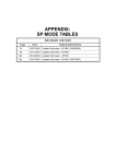
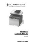
5.3.3 DISPLAY APS DATA (SP 4301 1)
- Sensor Positions The APS (auto paper select) sensors are arranged as shown in the diagram.
- Reading the Data Example 1
Example 2
1
1. Paper Size: 11000000 8 /2x13
1. Paper Size: 00110000 A4
2. DF Open: 1
2. DF Open: 0
Example 1 indicates that the paper size and its orientation is "81/2 x 13 SEF," and that the
document feeder (or platen cover) is open. Example 2 indicates that the paper size and its
The "Paper Size" data starts with eight digits. The first digit indicates the output of L2; the
second digit, L1; the third digit, W2; and the fourth digit, W1. The other four digits (from the
fifth through the eighth) are always "0000." In Example 1, the APS sensors L2 and L1
detect paper (W2 and W1 do not).
In Example 2, APS sensors W2 and W1 detect paper (L2 and L1 do not). The paper size
and its orientation is based on the outputs of these four APS sensors.
The "DF Open" data shows "1" or "0," indicating if the document feeder (or platen cover) is
open or closed respectively. The data is based on the output of the platen cover sensor [A].
SM
5-43
B245/B276/B277
Service
Tables
orientation is "A4 LEF," and that the document feeder (or platen cover) is closed.
Using SP Modes
5.3.4 MEMORY CLEAR
The basic machine (the machine without the optional controller box) stores all the data in
the NVRAM on the BICU. The data is cleared by SP 5801 2 (see list on the following page).
002
Main Motor Reverse
003
Quenching Lamp
The DDST machine (the machine with the optional controller box) stores the engine data in
the NVRAM on the BICU, and stores the other data in the NVRAM on the optional
controller. To distinguish between the engine data and the other data, see SP 5801 3
through 15. This service program (SP 5801) manages the controller data. Any data that is
not handled by SP 5801 is the engine data. The data in the BICU NVRAM (engine data) is
cleared by SP 5998 1, while the data in the controller NVRAM (controller data) is cleared by
SP 5801-xxx (see list on the following page).
002
Main Motor Reverse
003
Quenching Lamp
Machine
Basic
Data
All data
NVRAM
BICU
Cleared by
Remarks
SP 5801 2
Any data other
Engine data
BICU
SP 5998 1
than controller
data
SCS, IMH, MCS,
Copier
application,
DDST
Printer
Controller data
Controller
SP 5801-xxx
application,
Scanner
application, Web
service/network
application, NCS,
R-Fax, DCS, UCS
B245/B276/B277
5-44
SM
Using SP Modes
- Exceptions SP 5801 2 (basic machine) and SP 5998 1 (DDST machine) clears most of the settings and
counters stored in the NVRAM on the BICU (the values return to their default values).
However, the following settings are not cleared:
1. SP 5807 (Area Selection)
2. SP 5811 1 (Serial Num Input [Code Set])
3. SP 5811 3 (Serial Num Input [ID2 Code Display])
4. SP 5812 1 (Service TEL [Telephone])
5. SP 5812 2 (Service TEL [Facsimile])
6. SP 5907 (Plug & Play)
7. SP 7 (Data Log)
8. SP 8 (History)
Use SP 5802 2 (basic machine) or SP 5998 1 (DDST machine) after you have replaced the
BICU NVRAM or when the BICU NVRAM data is corrupted. When the program ends
normally, the message "Completed" shows. When you have replaced the controller
NVRAM or when the controller NVRAM data is corrupted, use SP 5801 1. The message is
the same as the basic machine.
- With Flash Memory Card
Upload the NVRAM data to a flash memory card (
2.
Print out all SMC data lists (
p.5-44).
p.5-52).
Be sure to print out all the lists. You have to manually change the SP settings
if the NVRAM data upload ends abnormally.
3.
Select SP 5801 2.
4.
Press the OK key.
5.
Select "Execute." The messages "Execute?" followed by "Cancel" and
"Execute" shows.
6.
Select "Execute."
7.
When the program has ended normally, the message "Completed" shows. If the
program has ended abnormally, an error message shows.
8.
Press the cancel key.
9.
Turn the main switch off and on.
10. Download the NVRAM data from a flash memory card (
SM
5-45
p.5-44)
B245/B276/B277
Service
Tables
1.
Using SP Modes
- Without Flash Memory Card p.5-52).
1.
Print out all SMC data lists (
2.
Select SP 5-801 (basic machine) or SP 5998 1
3.
Press the OK key.
4.
Select "Execute." The messages "Execute?" followed by "Cancel" and
"Execute" show.
5.
Select "Execute."
6.
When the program has ended normally, the message "Completed" is displayed.
If the program has ended abnormally, an error message shows.
7.
Turn the main switch off and on.
8.
Adjust the printer and scanner registration and magnification (
9.
Refer to the SMC lists, and enter any values that differ from the factory settings.
p.3-60).
Double-check the values for SP 4901.
10. Adjust the standard white level (SP 4428).
11. Initialize the TD sensor (SP 2214).
12. Check the copy quality and the paper path.
5.3.5 INPUT CHECK (SP 5803)
- Conducting an Input Check 1.
Select SP 5803.
2.
Select the number (see the table below) corresponding to the component.
3.
Select "Execute." The copy mode is activated.
4.
The symbols "01H" or "00H" will show (see the table below to cross-reference
these symbols).
- Input Check Table Num.
Sensor/Switch
01H
00H
001
Safety SW
Open
Closed
002
Safety SW-LD 5V
Open
Closed
003
Right Cover SW
Open
Closed
004
Right Low Cover SW
Open
Closed
005
Tray Cover SW
Open
Closed
006
Upper Relay S
Paper detected
Not detected
007
Lower Relay S
Paper detected
Not detected
B245/B276/B277
5-46
SM
Using SP Modes
Sensor/Switch
01H
00H
008
Vertical Trans S
Paper detected
Not detected
009
Registration Sensor
Paper detected
Not detected
010
Exit Sensor
Paper detected
Not detected
011
Duplex Inverter S
Paper detected
Not detected
012
Duplex Entrance S
Paper detected
Not detected
013
Duplex Exit S
Paper detected
Not detected
014
By-pass PE S
Paper detected
Not detected
015
By-pass P Size S
*1
016
Upper PE S
Paper detected
Not detected
017
Lower PE S
Paper detected
Not detected
018
Upper P Size SW
*1
019
Lower P Size SW
*1
020
BK-Upper Paper End S
Paper detected
Not detected
021
BK-Lower Paper End S
Paper detected
Not detected
022
BK-Up P Size SW
*1
023
BK-Low P Size SW
*1
024
BK-Up P Height S
*2
025
BK-Low P Height S
*2
026
BK-Upper Lift S
At upper limit
028
BK type
*3
030
Duplex Installed
Installed
Not installed
031
Lower Lift S
At upper limit
Not at upper limit
032
Main M Lock
Locked
Not locked
033
Polygon M Lock
Locked
Not locked
034
BK-Lift M Lock
Locked
Not locked
035
Total CO Install
Installed
Not installed
036
Key CO Install
Installed
Not installed
037
L-Synchronization
Detected
Not detected
038
DF-Position S
Detected
Not detected
039
DF-Cover Open S
Detected
Not detected
040
DF-Original Set S
Detected
Not detected
041
DF-Registration S
Detected
Not detected
042
DF-Exit S
Detected
Not detected
SM
5-47
Not at upper limit
B245/B276/B277
Service
Tables
Num.
Using SP Modes
Num.
Sensor/Switch
01H
00H
043
DF-Trailing S
Detected
Not detected
044
DF-Reverse S
Detected
Not detected
045
Platen Cover S
Open
Closed
046
1 bin Installed
Installed
Not installed
047
1 bin Exit S
Paper detected
Not detected
048
1 bin Paper S
Paper detected
Not detected
049
1 bin Tray S
Open
Closed
050
Fan Motor Lock
High speed
Not high speed
051
2 Tray BK Install
Installed
Not installed
053
HP Sensor
Detected
Not detected
054
Duplex Fan M Lock
Locked
Not locked
*1 Paper Size
Copier
00
01
Europe
Not set
A4 LEF
Not set
A4 LEF
Not set
A4 LEF B5 LEF
North
America
China
Paper Feed
Unit
Europe
North
America
China
00
01
02
03
8Hx13
8Hx13
LT SEF
SEF
06
07
LT LEF
--
A3 SEF
LG SEF LT LEF
--
DLT SEF
A4 SEF A5 LEF
04
05
Not set LT SEF LG SEF A4 LEF --
Not set LT SEF LG SEF A4 LEF --
Not set LT SEF LG SEF A4 LEF --
B245/B276/B277
05
A4 SEF A5 LEF
SEF
03
04
5-48
0A
DLT
SEF
DLT
SEF
DLT
SEF
B4 SEF --
0C
0E
A3 SEF
0F
A4 SEF LT LEF A3 SEF
A4 SEF LT LEF A3 SEF
A4 SEF LT LEF A3 SEF
SM
Using SP Modes
By-Pass
Tray
04
0C
08
00
01
8x13
03
02
06
A4 SEF A3 SEF A3 SEF
Europe
A5 SEF A5 SEF A5 SEF A5 SEF
North
HLT
HLT
HLT
HLT
HLT
America
SEF
SEF
SEF
SEF
SEF
China
B6 SEF B6 SEF A5 SEF A5 SEF B5 SEF A4 SEF B4 SEF A3 SEF
SEF
LG SEF
DLT
DLT
SEF
SEF
- *2 Paper Amount 10
Near end
11
About 25%
00
About 75%
00
About 100%
00
None
20
2-tray paper feed unit
30
1-tray paper feed unit
SM
Service
Tables
- *3 Available Paper Feed Unit -
5-49
B245/B276/B277
Using SP Modes
5.3.6 OUTPUT CHECK (SP 5804)
- Conducting an Output Check –
To prevent mechanical or electrical damage, do not keep an electrical
component on for a long time.
1.
Select SP 5804.
2.
Select the number (see the table below) corresponding to the component.
3.
Select "ON."
4.
To stop the operation, select "OFF."
- Output Check Table Number 005, 006, 040, and 041 may not respond when the fusing temperature is
high.
Num.
Component
001
Main Motor Forward
002
Main Motor Reverse
003
Quenching Lamp
004
Toner Supply Motor Forward
005
Fan Motor High
006
Fan Motor Low
007
Registration Clutch
008
By-pass Feed Clutch
009
Upper Feed Clutch
010
Lower Feed Clutch
011
BK-Low Lift Motor Up
012
BK-Low Lift Motor Down
013
Relay Clutch
014
BK-Relay Clutch
015
BK-Upper Feed Clutch
016
BK-Lower Feed Clutch
017
BK-Lift Motor
018
BK-Up Lift Motor Up
B245/B276/B277
5-50
SM
Using SP Modes
Component
019
BK-Up Lift Motor Down
020
Duplex Inv Motor Reverse
021
Duplex Inv Motor Forward
022
Duplex Trans Motor
023
Duplex Gate Solenoid
024
Duplex Inv Motor Hold
025
Dup Trans Motor Hold
026
Polygon Motor
027
Polygon M/LD
028
LD
029
DF-Transport Motor
030
DF-Feed Motor
031
DF-Feed Clutch
032
DF-Pickup Solenoid
033
DF-Stamp Solenoid
034
DF-Gate Solenoid
035
1 bin Gate Solenoid
036
1 bin Tray Motor
037
1 bin Tray Motor Hold
038
Fusing Solenoid
040
Duplex Fan Motor High
041
Duplex Fan Motor Low
SM
Service
Tables
Num.
5-51
B245/B276/B277
Using SP Modes
5.3.7 SERIAL NUMBER INPUT (SP 5811)
- Specifying Characters SP 5811 1 specifies the serial number. For the basic machine (the machine without the
optional controller), you use the numeric keypad. For the DDST machine (the machine with
the optional controller), you use the numeric keypad and the optional operation panel.
A serial number consists of 11 characters. You can change each character by pressing one
,
of the first 11 keys on the numeric keypad (
For example, when you press the
,
, ... ,
,
).
key, the first character of the serial number changes
as follows:
0
1
2
...
When you press the
8
9
A
B
...
X
Y
Z.
key, the second character changes likewise.
You can specify a digit ("0" to "9") or a capital letter ("A" to "Z") for the first four characters of
a serial number, and you can specify a digit in the other seven characters (not capital
letters).
5.3.8 NVRAM DATA UPLOAD/DOWNLOAD (SP 5824/5825)
This procedure is for the basic machine only.
Make sure that you turn off the main switch before inserting or removing a flash
memory card. Installing or removing a flash memory card while the main switch
is on may damage the BICU or memory.
- Overview You can copy the data from the NVRAM to a flash memory card (NVRAM Upload), or from
a flash memory card to the NVRAM (NVRAM download).
SP 5824 1
From the BICU to a flash
(NVRAM Upload)
memory card
SP 5825 1
From a flash memory
(NVRAM Download)
card to the BICU
You should execute NVRAM Upload before replacing the NVRAM or before executing SP
5801 2 (
p.5-37). You can copy back the data from the flash card to the NVRAM as
necessary.
B245/B276/B277
5-52
SM
Using SP Modes
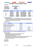
- NVRAM Upload (SP 5824 1) -
1.
Turn off the main switch.
2.
Remove the card cover [B] (1 rivet).
3.
Turn the face of the flash memory card [A] ("A" is printed on it) toward your
Service
Tables
left-hand side, and insert it into the card slot.
4.
Turn on the main switch.
5.
Start the SP mode and select SP 5824 1.
6.
The machine erases the settings on the card (if any), then writes the machine’s
settings to the flash memory card. This takes about 20 seconds. If uploading
fails, an error message appears. If an error message appears, retry the upload
procedure.
7.
Turn off the main switch.
8.
Remove the memory card.
SM
5-53
B245/B276/B277
Using SP Modes
- NVRAM Download (SP 5825 1) SP 5825 1 copies the data from the flash memory card to the NVRAM. The following data is
NOT copied (the data in the NVRAM remains unchanged).
SP 8221 1 (ADF Original Feed [Front])
SP 8221 2 (ADF Original Feed [Back])
SP 8381 1 (Total: Total Printer Pages)
SP 8382 1 (Copy Application: Total Print Pages)
SP 8391 1 (Large Size Print Pages [A3/DLT, Larger])
SP 8411 1 (Prints Duplex)
1.
Turn off the main switch.
2.
Remove the card cover [B] (1 rivet).
3.
Turn the face of the flash memory card [A] ("A" is printed on it) toward your
left-hand side, and insert it into the card slot.
4.
Turn on the main switch.
5.
Start the SP mode and select SP 5825 1.
6.
The machine erases the current settings, then writes the new settings onto the
NVRAM on the BICU board. This takes about 1 second. If downloading fails, an
error message appears. If an error message appears, retry the download
procedure.
7.
Turn off the main switch.
8.
Remove the memory card.
B245/B276/B277
5-54
SM
Using SP Modes
5.3.9 FIRMWARE UPDATE PROCEDURE
This section shows how to update the firmware.
The machine has the following firmware programs
Firmware Type
SP Mode
Version
Engine (BICU)
7801 2
B2435581 Ver 0.04 EXP
DDST (Printer/Scanner)
7801 15
A.001
Service
Tables
Engine (BICU) Firmware Update Procedure
1.
Turn the main switch off.
2.
Remove the card cover [B] (1 rivet).
3.
Insert the flash memory card [A].
4.
Press down the power switch on the operation panel and hold it, and turn on the
main switch.
5.
SM
Select "Execute" [C].
5-55
B245/B276/B277
Using SP Modes
6.
Do not touch any key while the message "Load Status..." shows. This message
indicates that the program is running.
7.
Make sure the message "End Sum..." shows. This message indicates that the
program has ended normally.
8.
Turn off the main switch.
9.
Remove the flash memory card.
10. Replace the card cover [B] (1 rivet).
11. Turn the main switch on.
12. Check the operation.
DDST (Printer Scanner) Update Procedure
1.
Turn the main switch off.
B245/B276/B277
5-56
SM
Using SP Modes
2. Remove the slot cover [A] (1 x
).
Service
Tables
3. Insert the flash memory card [B] as shown above.
4. Turn on the main power switch.
5. Push the printer application key [C].
6. Push the OK key [D] and then push Execute.
SM
5-57
B245/B276/B277
Using SP Modes
Do not turn the machine off while the message “Now Writing” shows. This
message indicates the program is running.
Make sure the message “Completed” shows. This message indicates the
program has successfully ended.
7. Turn off the main switch.
8. Remove the flash memory card.
9. Replace the slot cover [A] (1 x
B245/B276/B277
).
5-58
SM
Using SP Modes
5.3.10 TEST PATTERN PRINT (SP 5902 1)
- Executing Test Pattern Printing 1.
Specify the pattern number and press the OK key.
2.
Press the copy start key. The copy mode is activated
3.
Specify copy settings and press the
key.
4.
To return to the SP mode, press the
key.
- Test Patterns Test Patterns Using VCU
No.
Pattern
(No print)
1
Vertical Lines (Single Dot)
2
Horizontal Lines (Single Dot)
3
Vertical Lines (Double Dot)
4
Horizontal Lines (Double Dot)
5
Grid Pattern (Single Dot)
6
Grid Pattern (Double Dot)
7
Alternating Dot Pattern
8
Isolated one dot
9
Black Band (Horizontal)
10
Trimming Area
11
Argyle Pattern (Single Dot)
12
Grayscales (Horizontal)
13
Grayscales (Vertical)
14
Grayscales (Vertical/Horizontal)
15
Grayscales (Vertical/Horizontal Overlay)
16
Grayscales With White Lines (Horizontal)
17
Grayscales with White Lines (Vertical)
18
Grayscales with White Lines (Vertical/Horizontal)
SM
Service
Tables
0
5-59
B245/B276/B277
Using SP Modes
Test Patterns Using IPU
No.
Pattern
30
Vertical Lines (Single Dot)
31
Horizontal Lines (Single Dot)
32
Vertical Lines (Double Dot)
33
Horizontal Lines (Double Dot)
34
Isolated Four Dots
35
Grid Pattern (Double Dot)
36
Black Band (Vertical, 1024 Dots)
37
Grayscales (Horizontal, 512 Dots)
38
Grayscales (Vertical, 256 Dots)
39
ID Patch
40
Cross
41
Argyle Pattern (128-Dot Pitch)
42
Square Gradation (64 Grades)
43
Square Gradation (256 Grades)
44
Grayscales (Horizontal, 32-Dot Width)
45
Grayscales (Vertical, 32-Dot Width)
46
Trimming Area (A3)
47
A4 Gradation Patches 1 (128 Grades)
48
A4 Gradation Patches 2 (128 Grades)
49
Trimming Area (A4)
Test Patterns Using SBU
No.
Pattern
51
Grid Pattern (double dot)
52
Gray scale 1 (256 grades)
53
Gray scale 2 (256 grades)
B245/B276/B277
5-60
SM
Using SP Modes
5.3.11 PAPER JAM COUNTERS (SP 7504)
The table below lists the menu numbers (the last three digits of SP 7504 XXX), and the
paper jam timings and locations.
Code
001
Paper jam occurs at power on.
010
Paper does not reach the registration sensor (from a paper tray).
011
Paper does not reach the relay sensor.
012
Paper is caught at the relay sensor.
021
Paper does not reach the vertical transport sensor.
022
Paper is caught at the vertical transport sensor.
031
Paper does not reach the vertical transport sensor in the optional paper feed
unit.
032
Paper is caught at the vertical transport sensor in the optional paper feed unit.
050
Paper does not reach the registration sensor (from the by-pass tray).
060
Paper does not reach the registration sensor during reverse-side printing (for
duplex printing).
Paper is caught at the registration sensor.
120
Paper is caught at the exit sensor (previous page).
121
Paper does not reach the exit sensor.
122
Paper is caught at the exit sensor.
123
Paper does not reach the duplex inverter sensor (from the registration roller).
125
Paper is caught at the duplex inverter sensor.
126
Paper does not reach the duplex entrance sensor.
127
Paper is caught at the duplex entrance sensor.
128
Paper does not reach the duplex exit sensor.
129
Paper is caught at the duplex exit sensor.
130
Paper does not reach the one-bin tray.
131
Paper is caught at the one-bin tray.
SM
5-61
Service
Tables
070
B245/B276/B277
Using SP Modes
5.3.12 SMC PRINT (SP 5990)
SP 5990 outputs machine status lists.
1.
Select SP 5990.
2.
Select a menu:
Basic machine: 001 All, 002 SP, 003 UP, 004 Log, or 005 Big Font
DDST machine: 001 All (Data List), 002 SP (Mode Data List), 003 User Program,
004 Logging Data, 005 Diagnostic Report, 006 Non-Default, 007 NIB Summary,
008 Net File Log, 021 Copier User Program, 022 Scanner SP, 023 Scanner User
Program, 040 Parts Alarm Counter Print, 064 Normal Count Print, 065 User
Code Counter, 066 Key Operator Counter, 067 Contact List Print, 069 Heading1
print, 071 Heading3 print, 072 Group List Print, 128 ACC Pattern, 129 User Color
Pattern, or 160:ACC Pattern Scan
3.
4.
The output given by the menu "Big Font" is suitable for faxing.
Press the "Execute" key.
Basic machine: The copy mode is activated.
Specify copy settings and press the
DDST machine: The machine status list is output.
To return to the SP mode, press the
B245/B276/B277
key. The machine status lists is output.
key.
5-62
SM
Using SP Modes
5.3.13 ORIGINAL JAM HISTORY DISPLAY (SP 7508)
- Viewing the Copy Jam History You can view the information on the most recent 10 events. The information on older
events is deleted automatically.
The information on jam history is saved in the NVRAM.
1.
Select SP 7508.
2.
Select one of the menu items ("Latest 1" through Latest 10").
3.
Press the OK key. The summary of the jam history shows.
4.
To view more information, select "Detail."
Jam History Codes
Meaning
210
Original does not reach the registration sensor.
211
Original caught at the registration sensor.
212
Original does not reach the original exit sensor.
213
Original caught at the original exit sensor.
214
Original does not reach the original reverse sensor.
215
Original caught at the original reverse sensor.
Service
Tables
Code
5.3.14 ADF APS SENSOR OUTPUT DISPLAY (SP 6901)
- Sensor Positions Large to Small
W1
1
0
0
1
W2
0
0
1
1
SM
5-63
B245/B276/B277
Using SP Modes
- Reading Data W1
W2
L1
0
0
0
0
0
0
1
1
0
1
0
Paper Size
L2
0
1
NA
EU/AA
—
B5 LEF
11" x 17"
B4
1
A5 LEF
8 /2" x 5 /2" LEF
1
0
1
1
0
8 /2" x 11" SEF
A4 SEF
1
1
1
1
81/2" x 14"
81/2" x 13"
1
0
0
0
11" x 81/2" LEF
A4 LEF
1
0
1
1
11" x 17"
A3
1
1
1
1
0
0
5 /2" X 8 /2" SEF
A5 SEF
1
1
1
0
—
B5 SEF
1: Detected
B245/B276/B277
5-64
SM