1
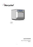
KR-1338/1668
KR-1338/1668
SERVICE
Î
¬ Ê
Ð Ö
ÞMANUAL
² á
10.4 TFT COLOR MARINE RADAR
TABLE OF CONTENTS
1.GENRAL
1.1 Outline
1.2 Boards & Major Components
1.3 Specifications
1
1
2
3
2.BLOCK DESCRIPTION
6
2.1 Overview
2.2 Display Unit
Block Diagram of Power Supply
Block Diagram of Processor PCB Main 0910
2.3 Transceiver Unit
Block Diagram of IF 0711
Block Diagram of Modulator
2.4 Different Points of Similar PCBs
3. ADJUSTMENT
3.1 Adjustment of Display Unit
Location of Parts on MAIN 0910
VIDEO Signal adjustment
Location of parts on PWR-0913
3.2 Adjustment of Scanner Unit
Location of parts on MOD-0904
Location of Parts on IF-0711
Location of PCBs in Transceiver Module (KR-1668)
BEARING SIG GEN Board (HBP0904)
Location of Parts on MOD 0904B
Location of Parts on IF-0711
4. MAINTENANCE
4.1 Remarks on Replacement of Major Parts
4.2 Life Expectancy of Expendable Parts
4.3 Menu tree
6
7
9
10
14
15
17
18
19
20
24
25
28
29
30
31
32
32
33
34
35
35
36
37
5.TROUBLESHOOTING
5.1 Outline
5.2 Troubleshooting Flow Charts
5.3 Message Indication
38
38
39
51
Display Unit Exploded view
52
Scanner Unit Exploded View
54
Schematic circuit diagram
58
1. GENERAL
1.1 Outline
This manual provides the information necessary for the servicing and adjustment
of the radars MODEL 1338, 1668.
The antenna unit uses a Log IF amplifier.
The table below shows the major specifications of the each model. The same
program is installed on all models, but the menu setting through factory menu is
different between the models.
Functions
KR-1338
KR-1668
Maximum range
36 NM
64 NM
Program Number
1002XX
Tuning Voltage
(displayed at manual tuning)
4.9 V to 32V
Antenna Rotation
about 24 rpm
Antenna Rotation
4 kW
XX
4/6 kW
KR-1338-SME-1
The major parts and P.C. Boards used in the display and scanner units are tabulated
on the next page.
1
1.2 Boards & Major Components
Board
DISPLAY
UNIT
KR-1338
KR-1668
PROCESSOR Board
MAIN 0910
POWER SUPPLY Board
PWR 0913
FILTER Board
FIL 0912
PANEL Board
KEY 0912
MODULATOR Board
MOD 0904A
MOD 0904B
IF AMP Board
RTB Board
SCANNER
UNIT
BEARING SIG GEN Board
MIC Board
IF 0711
-
HBP 0905
RCN 0907
NJT-1968B
MIC
Cable
CON 0906
Magnetron
MAF1421B/MSF1421B
Circulator
FCX73C
Scanner Motor
BM-9256
Signal Cable
MAF1421/MAF1422B
BM-8256
KRC-003-10(10m)
KRC-003-15(15m)
KRC-003-20(20m)
KRC-003-30(30m)
KR-1338-SME-2
2
1.3 Specifications
SCANNER UNIT
KR-1668
KR- 1338
Radiator Type
Slotted Waveguide Array
Radiator Length
56cm
120 cm
Horizontal Beamwidth
4
1.9
Vertical Beamwidth
Within 20
Sidelobe
of mainlobe
Attenuation
Outside 20
of mainlobe
Polarization
20
22
-18 dB or less
-24 dB or less
-23 dB or less
-30 dB or less
Horizontal
Antenna Rotation
24 rpm nominal
Scanner Housing Stureruct
Radome
Open nominal
Compass Safe Standard
Distance
Steering
0.9 m
1.0 m
0.7 m
0.74 m
KR-1338-SME-3
TRANCEIVER
KR-1338
KR-1668
Magnetron
MAF1421B/MSF1421
MAF1421/MAF1422B
Frequency &Modulation
9410 M Hz
Peak Output Power
4 kW nominal
Pulse Length &
Pulse Repetition
Rate
30M Hz,P0N
6 kW nominal
0.08 S, approx 2100 Hz Short Ranges:0.25 nm -1.5 nm)
0.3 S, approx 1200 Hz(Middle Ranges: 1.5nm - 3nm)
0.8
S, approx 600 Hz(Long Ranges: 3 nm and above)
Modulator
FET Switch
Duplexer
Circulator with diode limiter
Receiver Front End
Tuning
MIC(Microwave IC)
Automatic or Manual
Intermediate Frequency
60 M Hz
Bandwidth
25 MH z(0.08
S, 0.3
S), 3 M H z (0.8 S)
KR-1338-SME-4
3
DISPLAY UNIT
KR- 1338
10.4 LCD(LED backlight ,32 bit TFT color LCD)
Picture Tube
KR-1338:36 nm
KR-1668:64 nm
Range Scale(nm)
0.125 0.25 0.5 0.75
Range Ringe Interval
Number of Rings
Bearing Resolution
KR-1668
1 1.5 2 3 4 6 8 12 16 24 36 48 64
1/16 0.125 0.125 0.25 0.25 0.5 0.5 1 1 2 2 3 4 6 12 12 16
2
2
4
4
3
4
3 4 3 4 3 4 4 4 4 3 4 4
1.9
Range Discrimination
Better than 20 m
Bearing Accuracy
1
Better than 25 m
Minimum Range
Range Ring Accuracy
VRM Accuracy
Input/Output Terminal
0.9 or 8m,whichever is the greater
NMEA (three input): NMEA 0183
NMEA (output) :NMEA 0183($RATLL, $RARSD, $RATLL:
Internal easy ARPA version.)
External Buzzer (output) : +12 V source pulse Open Collector
Slave Display (output): TRU-HD, BP, TRU-TRIG, VIDEO
Nav Data
Compass safe Standard
Distance
Steering
NMEA 0183 Format ( :any talker)
$ APB, $ BWC, $ BWR, $ D PT, $ GGA, $ GLL,
$ GLC, $ GTD, $ HDG, $ HDM, $ HDT, $ MDA, $ MTW,
$ RMA, $ RMB, $ RMC, $ VTG, $ VHW, $ XTE,
0.75 m
0.6 m
KR-1338-SME-5
4
ENVIRONMENTAL CONDITIONS
KR-1338
Ambient
Temperature
Scanner Unit
-25
to +70
Display Unit
-15
to +55
Humidity
Relative humidity 93%
Vibration
-IEC 60945
KR-1668
2% or less at +40
3
KR-1338-SMJ-6
POWER SUPPLY & POWER CONSUMPTION
KR-1338
KR-1668
10.5 V to 40.0V
DC Power
48 W approx
56 W approx
KR-1338-SME-7
5
2. BLOCK DESCRIPTION
2.1 Overview
The simpified block diagram of the system is illustrated below.
Scanner Unit
Antenna
Display Unit
Mag.
MIC
Mod.
IF
Amp
HD.BP
Video
Trigger
Processor
LCD
RF Module
Panel
Power
Ship ' s mains
Nav.
Gyro
TX
The trigger pulse from the PROCESSOR Board is delivered to the MODULATOR
Board, oscillates the magnetron, and then radar wave is emitted from the radiator.
RX
The 9.4 Ghz echo signal received by the antenna is converted to 60 Mhz signal by
the MIC, amplified by IF Amp, and fed to the PROCESSOR Board as video signal.
It is digitally processed and then displayed on the LCD.
6
2.2 Display Unit
Power Supply Circuit (PWR 0913)
The constant voltage generator Q1 is in operation even when power switch is off,
ship's mains is supplied. The power supply circuit is basically consists of a main
inverter and a sub inverter. The main inverter derives the isolated line voltages
+12 V/ANT+12 V and -12 V/ANT -12 V from the main input. The sub inverter
derives +5 V and +32 V from +12 V output of the main inverter.
Main inverter
The PWR switch becomes "open" when it is set to on position.
When the PWR switch is pressed, about 9 V is input via PWR line (P1302 #13),
Q2 is on, and DC+10 V is applied to the PWM.
When power is supplied to the PWM controller, it starts operation and alternately
turns on and off two switching FETs Q3/Q4 connected to the primary widing of
T1. The resultant AC voltage obtained on the secondary windings are rectified and
smoothed to +12 V and -12 V, and delivered to various circuits in the equipment.
The voltage taken from the +12V line is fed back to the PWM controller through
the Vr1 to maintain the +12 V output constant.
Sub inverter
U5 and the associated circuit form a PWM switching regulator for +5V and +32V.
The voltage taken from +5 V line is fed back to U5 through R37 resistance to
maintain the +5 V output constant.
Protectors
Protection of power supply circuit is achieved by stopping the drive signals to the
switching FETs Q3/4.
7
Qverload on +5 V and + 32 V line is detected by U6. Overload on +12 V(MOTOR+)
line is detected by U7. When the +5 V and + 32 V line is reduced by a heavy load,
U6 or U7 becomes condctive and consequently disables the PWM controller through Q6, Q7 and Q8. Overcurrent on the main input line is detected by R13, R14
and R15. The voltage drop across Q6, Q7 and Q8 bec- omes large when the inverter is overload. Overcurrent detector U3 disables PWM inverter U2 when the
voltage drop exceeds a certain level.
Overvoltage of mains input is detected by the U1. When the input voltage exceeds
41.6 V, the U1 becomes active and disables PWM controller U2
Scanner motor power (ANT+12V/ -12 V)
+12 V and -12 V (ANT +12 V/ANT -12 V) are used to drive 24 V scanner motor.
The power to the motor is turned on/off by the relay(K1) on the POWER SUPPLY
Board. The relay control signal from the SPU Board is supplied to Q52 and Q53
on the POWER SUPPLY Board. Pressing the TX key changes the ANT SW signal
state from 5 V to 0 V, and K1 is on to supply +12V.
.
8
BLOCK DIAGRAM OF POWER SUPPLY
9
BLOCK DIAGRAM OF PROCESSOR PCB MAIN 0910
10
AUTOMATIC TUNING
There are two types of automatic tuning: peak search and short search. The tuning
voltage differs from model to model.
KR-1338/1668 : 5 V to 28 V
Peak search: Tuning voltage (TUNING), point in the figure below, is searched
in the tuning voltage range 5V to A 28V. Tuning Indicator voltage
(TUNING IND) is maximum at point .
Search conditions: After initial tuning adjustment.
Search time: 3 sec approx
Short search: Maximum tuning indicator voltage A is searched in the tuning
voltage range of
2.5V.
A initial tuning adjustment.
1)After
2)When tuning method is switched from manual to automatic.
3)When the radar is switched from ST-BY to TX.
4)When a range where pulselength is changed from short to middle
and from middle to long is selected.
Tracking: After short search, tracking takes place.
Tracking voltage: 0 V to 32 V
KR-1338/1668
11
TUNING INDICATOR
After tuning adjustment, peak TUNING IND voltages, , and
on page 2-5 are stored on to EEPROM.
in the figure
The automatic and manual tuning point A is also memorized. Using these data,
the tuning indicator extends more than 80% on ALL TX pulses.
Note that the extension on short pulse is shorter than on long pulse. The indication becomes shorter with the magnetron deteriorated.
MANUAL TUNING
The manual tuning voltage changes from 5 to 32 V on M 1668 at the steps
of about 0.1 V.
Manual Tuning is carried out by using omnipad: pressing "Right" side increases.
The TUNING continue voltage displayed on the screen differs by about 1V
from the measured voltage at P52 # 9. Manual Tuning and tuning adjustment
are required when automatic tuning is abnormal (that is ,low sensitivity).
CVT
FROM PANEL BOARD
P8
P/S
CONV.
CPU
D/A
CONV.
#5
#7
U2
#10
FVT
U9
U27
U20
#3
#8
P8
TUNING CONTROL
(TO RF UNIT)
#1
TUNING CONT. Operation (from power-on stand-by)
A square wave is automatically output as a TUNING CONT signal during standby just after power-on the model as follows.
F VT
34V
5V
C VT
0V
KR-1838/1968/1948
12
Heading and NAV data
Heading data in NMEA format HEADING DATA (HDT, HDG, HDM, VHW)and
NAV data (NMEA-0183)can be input from any NMEA input connection. THE
data from the KEY board(KEY 0912) to P8#3 of MAIN board .
NOTE:
1.If only one NMEA signal input may select any connection, if several connections
have time the signal input, be please main and the most commonly used signal
meets in the connection 1, because the complete signal's input is 1 comes the
synchronization by the connection, i.e. the connection 1 signal is fastest;
2.The NMEA signal after or before radar starting in may, but in signaling process,
if the NMEA port 1 loss of signal, will possibly cause other port data not to be
able to transmit normally. Must remove this kind of condition only to be able again
starting.
Turning on/off antenna rotation
The SPU board controls antenna rotation. In normal operation, the antenna
rotates during the TX condition. However, the antenna can be stopped during
the TX condition thru the Installation setup menu.
13
2.3 Transceiver Unit
MIC
The following description is for reference only.
As a general rule of thumb, the radar requires better noise figure (NF) and better
dynamic range. Both factors, however, are reciprocal. The NF affects long range
performance, while the dynamic range dose short range performance.
To improve noise figure, amplifier and MBS circuit into the MIC, RU-9360.
MIC w/RF amplifier
RF IN
W.G.TO
COAX CONV.
GND
NJT-1968B(MODEL 1338/1668)
LIMTER
FET AMP
DOUBLEBALANCED
MIXER
POWER
FET OSC.
(+5V)
(+5V to 35V)
Block Diagram of MIC NJT-1968B (MODEL 1338/1668)
14
IF OUT
BLOCK DIAGRAM OF IF 0711
15
Modulator
PRINCIPLE OF FET SWITCHING MODULATOR
High voltage is charged into C through R while the magnetron is inactive.
When the trigger is applied to the power MOS-FET, the FET turns on and the high
voltage appears at the primary winding of the pulse transformer. This transformer
boots the voltage, which makes the magnetron oscillate.
One advantage of this method is that the magnetron oscillates only when the FET
is conducive, that is the transmission pulsewidth can be changed by the TX trigger
pulsewidth. Therefore, parts such as relay and coil can be eliminated.
R
Charge
PULSE TRANS
C
Discharge
MAGNETRON
D
MOST-FET
HIGH VOLTAGE
TRIGGER
Modulator section simple block diagram
MODULATOR BOARD MOD-0904
The main function of the modulator section is to produce high voltage pulses to
drive the magnetron. To produce these pulse, the MODULATOR Board has a
modulator trigger circuit, modulator pulse generator and booster pulse transformer.
The modulator trigger circuit consists of U805 and associated components. This
circuit generates the pulses which cause modulation FETs Q805,Q806 to conduct.
The pulses are produced when the TX TRIG pulses from the display unit is received and U805 conducts. The voltage of the pulses is raised at pulse transformer
T802 until it is 3.5 kV. This circuit adjusts the electrical curent flowing into the
magnetron so it is 3 A.
The MODULATOR Board also contains the TX high voltage circuit and the magnetron heater circuit. The TX high voltage circuit charges capacitors with 300 V
high voltage produced at the primary windings of T801 and discharges them once
the TX TRIG pulse is received. The magnetron heater circuit produces stable +7.5V.
16
BLOCK DIAGRAM OF MODULATOR PCB MOD 0904
17
2.4 Different Points of Similar PCBs
1. How to set SPU (MAIN 0910) Board
This board is set at factory for use in the KR-1338. For use in the or 1668, change
the factory menu as below.
While pressing and holding down the GAIN(HM-OFF) control, press the [MENU]
key five times to display the factory menu.
[Factory MENU]
1. Max Range
2. Typ e
3. Model
4. Language
36 48 64
R G N
K
KR-1338 KR-1648
KR-1668
ENG
CHN
5. Default Setting
ENTER
3
<Press MENU key to escape >
M1338-SME-09D
1) MAX range
36 nm: KR-1338,
48 nm: KR-1648,
64nm: KR-1668
2) Type
R: Regular,
G: German,
N:Netherland,
K:Korea
3)Model
Selects the Antenna Unit.
KR-1338
KR-1648
KR-1668
4)Language
CHN: Chinese
English
5)Default Setting
Default settings (except factory menu) can be restored by selecting Default Setting
and pressing the [ENTER] key three times. Restart radar settings. After changing
the setting, the installation adjustment (heading, timing, etc.) Must be carried out
again.
2.MODULATOR board MOD-0904 A/B
E version of MOD-0904 is not compatible with A version. This is because B has a
larger pulse transformer.
18
3. ADJUSTMENT
WARNING
IMPORTANT!
SAFETY INFORMATION
Be sure to read all the safety information which
follows before perfoming any adjustment.
Hazardous Voltage
This equipment uses high voltage electricity which can SHOCK, BURN or cause
DEATH Always make sure the electrical power is turned off before attempting to
change a component or inspecting the inside of the equipment. A residual charge
may exist in capacitors, even with the equipment turned off. Always short all
supply lines to the chassis with an insulated screwdriver or a similar tool before
touching the circuit.
Working on the Scanner Unit Mast
Work on the scanner unit mast in dangerous, and doubly so if the proper precautions are not taken.
1. Post an appropriate warning sign near the display unit to indicate that work on
the scanner unit is being performed, to prevent accidental application of the power
to the scanner unit.
2. Wear a safety helmet and always be aware of where the scanner radiator is.
19
3.1 Adjustment of Display Unit
Display Unit, Front side of view
Power Connector
GND
OPTION
DJ-1 Connector
Fuse Holder
UPGRADE
GND
NMEA-1 Connector
GND
NMEA-2 Connector
Display Unit, Rear side of view
20
Inside of Display Unit, LCD
Inside of Display Unit, Processor PCB
21
Inside of Display Unit, Power PCB
22
Line Voltage
Item
Ratings
Test Point
Remarks
+12 V
12.1 to 12.3 V
DJ1-10(+)-DJ1-20(-)
+5 V
4.9 to 5.1V
DJ1-23(+)-DJ1-20(-)
+12 V
-11.6 to -12.8 V
DJ1-14(+)-DJ1-20(-)
ANT 12 V
12.0 to 12.3 V
DJ1-1(+)-DJ1-20(-)
ST-BY
KR-1338-SME-8
Output signals from DJ-1 connector
Test Item
TUNE
P/L A
P/L B
Ratings
Approx. 5 V to 28 V(KR-1338/1948/
1968)
Short pulse: 0 to 1.0V(L)
Medium pulse:7 to 12 V(H)
Long pulse: 7 to 12 V(H)
Short pulse: 0 to 1.0V(L)
Medium pulse:0 to 1.0 V(L)
Long pulse: 8 to 12 V(H)
Test Point
Remarks
DJ1-6(+) -DJ1-20(-)
Antenna Unit disconected TX, Auto tuning
DJ1-8(+) -DJ1-20(-)
Antenna Unit disconDJ1-7(+) -DJ1-20(-) ected Tx condition
Short pulse: 2000 to 2300 Hz
DJ1-2(+) -DJ1-20(-)
TRIGGER Pulsewidth: 10 to 20 s (All range)
Polarity: Positive Polarity 8 to 12 V(H)
KR-1338-SME-9
23
Location of parts on MAIN 0910
VR3
TP6
VR1
VR2
TP2
TP1
TP3
TP4
TP5
MAIN 0910 Board
Test Point on MAIN 0910
Tes t
Point
Test Item
Ratings
TP1
TRIGGER
3.3 Vpp
TP2
VIDEO
-4 Vpp
TP3
Gain level preset
TP4
STC Curve
TP5
VIDEO Preset
4 S: 1.0V to 1.2V
20 S: 2.0V to 2.3V
40 S: 2.6V to 2.8V
60 S: 3.0V to 3.2V
90 S: 4.0V to 4.5V
Remarks
TX Condition
TX Condition
GAIN VR: MAX
STC VR: MAX
-4 Vpp
(Neg. Polarity, main bang level)
TX Condition
TP6
TX TRIGGER
8 to 12V
KR-1338-SMC-10
24
VIDEO Signal adjustment
VIDEO signal adjustment is carried out in the processor board. This is a simplified
block diagram of the video amplified circuit.
VIDEO AMP
J52
VIDEO IN
Clutter level
TP7
<2
ANTI-LOG
Video level
TP5
Gain preset
TP3
Video Out
TP2
VR3
VR1
VIDEO
LEVEL
GAIN
PRESET
STC
Curve
TP4
A/C
RAIN,
GAIN
A/C
SEA
JS2
BEARING P
3
STC
HEADING P
4
Check Point
STC TRIG
A/C AUTO
STC
CURVE
SCAN
Video level
12V
VR2
JS2
Conditions
A/C AUTO
OFF
A/C SEA
fully counterclockwise
A/C RAIN
fully counterclockwise
TX on 12 nm
Table 3-5 video level
Rating
TP5 on
SPU pcb
(trigger
at TP1)
Adjuster
VR3
V 1 = 500 to 700 mV
V 2 = 4.2 0.2V
25
Conditions
A/C AUTO
A/C SEA
A/C RAIN
GAIN
Scanner
Gain preset
OFF
fully clockwise
fully counterclockwise
fully Clockwise
OFF
[INSTALLATION SETUP 1] menu
4. Ant on Tx : STOP
Table 3-6 Gain preset
Check Point
Adjuster
Rating
VR1
TP3 on
SPU pcb
(trigger
at TP1)
V = 0.04 to 0.06V
Conditions
STC curve
A/C SEA
GAIN
TX on 12nm
fully clockwise
fully Clockwise
Table 3-7 STC curse
Ant Height on
Installaion Setup menu
Check Point
Rating at 60 uS
point
TP4
3.1 0.1V
3.6 0.2V
2.5 0.2V
60uS
26
MED
LOW
HIGH
Adjuster
VR2
ANT height setting
Antenna height (STC curve adjustment) should be set
Radar at installation to match the STC curve with
installation conditions. This is especially important
when sea conditions changes over time - rotation of
the STC VR may erase both sea clutter and legitimate
targets if the STC curve is not suitable.
Setting in the field
1. Set antenna height on the Installation Setup 1 menu
If both sea clutter and echoes disappear, decrease
antenna height setting. If sea clutter cannot be completely eliminated, increase antenna height setting.
2. Adjust Vr2 on the SPU board. If both sea clutter and
targets disappear: increase voltage at 60 us point.
Note: The following step, adjustment of the STC,
should only be followed when step 1 and 2 do
not produce satisfactory results. Record the
factory setting before adjusting the STC.
3. Adjust STC. (Press the MENU key five times while
pressing and holding down the HM OFF control to
display the FACTORY menu. Operate the trackball to
change the maximum effective range of the STC.
27
Location of parts on PWR-0913
TP32
TP2
TP31
TP1
TP3
TP4
Test point on PWR-0913
Test Point
Test Point
TP1
+10 V
TP2
DC(-)
Test Point
8.2 to 9.5 V
-
TP3
Inverter Frequency 85.5 to 94.5 KHz
VR No
Remarks
-
-
-
-
-
-
VR 1
-
TP4
J1
J1
J1
J1
TP 31
+12 V
12.1 to 12.3 V
TP 32
+5 V
4.9 to 5.2 V
-
-
+12 V
-11.6 to -12.8 V
-
-
+32 V
30.0 to 35.0 V
-
-
#2(-)
#7(GND)
#3(+)
#7(GND)
KR-1338-SME-11
28
3.2 Adjustment of Scanner Unit
Location of PCBs in Scanner Unit KR 1338
MIC
(NJT1968)
Magnetron V801
MSF1421
MODULATOR
MOD0904
Read Swith
S801
IF AMP Board
IF0711
Scanner Motor B801
BM-9256
Inside of Scanner Unit
29
Location of parts on MOD-0904A
TP802
TP801
VR801
VR802
TP803
Test point on MOD-0904 A
Test Point
Test Item
Ratings
VR No
TP 801
TRIGGER
Same as MAIN 0910 TP6 in
Display Unit
-
TP 802
GND
-
-
-
ST-BY: 300 to 370 Vdc
TX: 290 to 330 Vdc(Long)
-
-
-
-
-
#1 TX-HV
#2 GND
TX
Condition
TP803
#3 +14V
13 to 17 Vdc
#4 Mag. Heater 7.4 to 7.6 Vdc
#5
0.25 to 1.2 Vdc(Short)
Mag. Current 0.7 to 1.2 Vdc(Medium)
0.9 to 1.1 Vdc(Long)
#6 GND
-
-
ST-BY
VR801
ST-BY
VR802
TX (Long)
Condition
-
KR-1338-SMC-12
30
Location of parts on IF-0711
TP1 TP5
TP7
TP8
TP9
TP3
TP10
Test point on IF-0711
Test Point
TP 1
TP 3
Test Item
Ratings
Center Frequency For factory adjustment
correction
Same as MAIN 0910 TP5
VIDEO output
in Display Unit
VR No
Remarks
T1, T2
-
-
-
T3, T4
-
TP 5
Tuning indicator
For factory adjustment
TP 7
+9 V
8.7 to 9.3 Vdc
-
-
TP 8
+5 V
4.7 to 5.3 Vdc
-
-
TP 9
-9 V
-8.7 to -9.3 Vdc
-
-
TP 10
-5 V
-4.7 to -5.3 Vdc
-
KR-1338-SME-13
31
Location of PCBs in Transceiver Module (KR-1668)
IF MAP Board IF0711
MIC
U801
Magnetron
V801
Transceiver Module
BEARING SIG GEN Board
HBP0904
TP803
J701
MODULATOR
Board
MOD0904
J812
J811
Transceiver Module, Cover removed
32
Location of Parts on MOD 0904B
TP801
TP802
TP803
Test point on MOD 0904B
Test Point
Test Item
Ratings
VR No
TP 801
TRIGGER
Same as MAIN 0910 Tp6 in
Display Unit
-
TP 802
GND
350 - 390
-
-
ST-BY: 300 to 370 Vdc
TX: 300 to 340 Vdc(Long)
-
-
-
-
-
#1 TX-HV
#2 GND
TX
Condition
TP803
#3 +14V
13 to 17 Vdc
#4 Mag. Heater 7.5 to 7.7 Vdc
#5
0.5 to 1.45 Vdc(Short)
Mag. Current 0.95 to1 .46 Vdc(Medium)
1.15 to 1.35 Vdc(Long)
#6 GND
-
-
ST-BY
VR801
ST-BY
VR802
TX (Long)
Condition
-
KR-1338-SMC-14
33
Ï Ô Ê ¾ µ ¥ Ô ª Ä Ú ² ¿ £ ¬ ¸ © Ê Ó Í ¼
Location of parts on IF-0711
TP1 TP5
TP7
TP8
TP3
TP9
TP10
Test point on IF-0711
Test Point
TP 1
TP 3
Test Item
Ratings
Center Frequency For factory adjustment
correction
Same as MAIN 0910 TP5
VIDEO output
in Display Unit
VR No
Remarks
T1, T2
-
-
-
T3, T4
-
TP 5
Tuning indicator
For factory adjustment
TP 7
+9 V
8.7 to 9.3 Vdc
-
-
TP 8
+5 V
4.7 to 5.3 Vdc
-
-
TP 9
-9 V
-8.7 to -9.3 Vdc
-
-
TP 10
-5 V
-4.7 to -5.3 Vdc
-
-
KR-1338-SMC-15
34
4. MAINTENANCE
4.1 Remarks on Replacement of Major Parts
Turn off the power before replacing any parts
Do not touch the magnetron while the radar is transmitting. Sufficient high voltage
exsts at the magnetron to cause death.
MAGENTRON
The magnetron emits a strong magnetic field. For this reason, remove wrist watch
before performing the replacement and use a non-magnetic screwdriver to dismount
the magnetron. The estimated life of the magnetron is 2000 hours, (including time
in stand-by), however actual life depends on usage.
1. Turn off the power.
2. Dismount the transceiver module.
3. Dismount and replace the magnetron.
4. When a new magnetron is fitted, allow at least 30 minute pre-heating under
ST-BY. Turn on the power and measure magnetron current . See Chapter 3 for heater voltage rating and potentiometer to adjust.
5. Transmit on long range and measure magnetron current. See Chapter 3 for magnetron current rating and potentiometer to adjust.
6. Reset "TX Hours" and "On Hours" on INSTALLATION SETUP menu. See page
4-3 for how to access this menu.
MIC
The MIC can be replaced individually. No adjustment is necessary after replacement.
SPU Board
Write down settings of MAIN and INSTALLATION menus before replacing the
board. Then, after replacing the board, reenter settings. (Reason: Settings are stored
in the E PROM(U48) on the SPU board.)
2
IMPORTANT: After replacing the board, the factory menu setting must be
carried out properly, otherwise the MIC will be damaged.
35
ROM
The SPU board uses Flush ROM(U36) to store a system program. The program
version number can be checked at "23. Self Check" on the MAIN menu.
[Self test]
Key test: Press each key and
check on-screen indication lights
Program No :0359139-1XX
ROM
: OK
RAM
: OK
Hours in use
Tx hou rse
000026.6 H
000 012.7 H
Program number and
revision level.
4.2 Life Expectancy of Expendable Parts
Parts
Type
Code No.
Life expectancy *1
BM-9256 000-139-918 more than 3000 hrs.
KR-1338
.
Scanner motor
Magnetron
Remarks
BM-8256
more than 5000 hrs.
KR-1668
MSF1421
more than 2000 hrs.*2
KR-1338
MAF1421
more than 2000 hrs.*2 KR-1338
MAF1422
more than 2000 hrs.*2
KR-1668
KR-1338-SMC-16
*1: Under normal operating condition.
*2: Hours during ST-BY are included.
36
4.3 Menu tree
MENU KEY
RINGS(Off,1,2,3,max)
EBL OFFSET Off On
SHIFT Off On
ZOOM Off On
MODE HU CU NU TM
DISP DATA
ECHO TARIL Off On
ECHO STRTCH Off ES 1
ARPA MENU
OTHER MENU
ES2
1 .Display
2 .AllCancel
3 .Vectpr ref
4 .Vectpr Leng
5 .History
6 .CPA SET
7 .TCPA SET
8 .AUTO ACQ
1 .Panel Dimmer 1,2,3,4
2 .Mark Brill 1,2,3,4
3 .HD Mark 1,2,3,4
4 .Characters 1,2,3,4
5 .Trail Tone Single Muiti
6 .Int Reject Off 1,2,3
7 .Pulselength Short Long
8 .Noise Reject Off On
9 .Trail Time
15S 30S 1M 3M 6M 15M 30M Cont
10 .Tone Auto Manu
11 .Disp Data Off Nav ARP All
12 .WPT Mark Off No
13 .EBL Ref Rel True
14 .VRM Unit nm km sm
15 .Watchman Off 5M 10M 20M
16 .STBY DISP Norm Econo Nav
17 .Guard Mode In Out
18 .Cursor Posi B/R,L/L
19.Alm Sense LV Low Mid High
36):1016
20 .Dead Sector Off On
36,48):1048
21 .Range
1/8 1/4 1/2 3/4 1 1.5/2 3 4 6 8 12 16 24, 36,48,64):1064
22.Color Setting
23.Self Test
24.Installation Setup
1 .Nav Talker All GPS
2 .Depth unit m fa ft
3 .Temp Unit
C, F)
4 .Hdg Sensor(Magnet,Gyro)
5 .Key Beep Off On
6 .Scan Stop Rotate Stop
7 .Dead Sector
8 .Tune/Video Adjustment
9 .Heading Alignment
10 .Sweep Timing Adjustment
11 .MBS Adjustment
12 .Ant Height Low Mid High
13 .STC Curve(Sharp,std Gntl)
14 .Ope Mode Master Slave
15 .Hours in Use
16 .TX Hours
37
5. TROUBLESHOOTHING
5.1 Outline
This chapter provides troubleshooting flow charts and describes error messages.
Error messages
When there is no bearing pulse signal the display unit shows BP-SIG-MISSING
and when is no heading signal, HD-SIG-MISSING. Check the antenna cable when
those indications appear.
Troubleshooting flow charts
The troubleshooting flow charts help the service technician to diagnose problems.
To use the flow charts. First find the symptom and its flow chart number in the
flow chart on page 5-2. Then, follow appropriate flow chart to troubleshoot
38
5.2 Troubleshooting Flow Charts
Start
Press Turn power on.
Yes
Nothing appears
on display
No
Flow chart 1
Yes
Abnormal display
No echoes nor
white noise.
No
No
Flow chart 7
Flow chart 2
Yes
Yes
Poor sensitivity.
No heading data.
No
Flow chart 8
No
Flow chart 3
Yes
Yes
No nav data.
No GAIN,STC,
FTC effect.
No
No
Flow chart 9
Flow chart 4
Yes
End
Yes
Key(s) inoperative.
No
Flow chart 5
Yes
Antenna dose not
rotate.
No
Flow chart 6
Yes
39
Symptom: Nothing appears on the display.
Flow chart 1
Keys beep when
pressed.
No(No power)
Check in-line fuse.
Yes(Equipment is powered)
LCD backlight
lights?.
No
Faulty LCD assy.
NG
OK?
OK
OK
Replace fuse,
Turn on power
Check LCD display signal
J1 on the SPU Board.
NG
Check input voltage at
connector J1351 on
display unit.
Results of
measurement.
NG
OK
Faulty ped PWR-0913
Faulty LCD assy.
(MAIN-0910)
OK
10.2 to 41.6 V
No
Faulty LCD assy.
Yes
Unplug antenna
connector DJ-1.
Faulty power cable,
power connector,
ship`s mains.
NG (No power)
Check voltage at P51,
#5(+5V),#2(+12V)on
MAIN-0910.
NG
OK
Faulty pcb MAIN-0910
40
Symptom: Display Abnormal
Flow chart 2
Check display output signal
on MAIN 0910J
OK?
NG
MAIN 0910 Fault
OK
Adjustment
display brill
NG
Check brill control circuit
OK
OK?
OK
END
LCD Fault
41
Symptom: No heading data.
Flow chart 3
Heading data format.
NMEA 0183's
HDT,HDM,HDG
Heading data indication
Heading data
indication.
Blank
Blank
***.*
Check CLK data at HDG
connector #3,#4 on
displau unit
***.*
Check HDT,HDM,HDG
output setting.
Turn power off and on.
Turn power OFF and ON.
OK?
OK?
OK?
NG
OK
Check HDT, HDM,
HDG output setting.
OK
Check HDT,HDM,HDG
output setting.
Heading data from heading
sensor momentarily interrupted.
OK?
OK?
NG
OK
(Normal)
OK
Faulty heading
Faulty pcb SPU-9211 sensor or its
interconnection
cable.
Heading data from heading
sensor temporarily interrupted.
NG
OK
Faulty heading sensor or
its interconnection cable.
Faulty pcb MAIN-0910 or
wrong heading data format.
42
NG
Symptom: No nav data.
Flow chart 4
Nav data indication.
All data shown by asterisks or blank.
Some data shown by
asterisks or blank.
Check nav equipment's
output sentences.
Check RD NMEA 1 / 2
connector on display unit
with oscilloscope.
OK?
OK?
NG
OK
NG
OK
Select sentences to be output.
Wrong data sentence format
selected at input or output
side.
Faulty pcb MAIN-0910
or NMEA 0183 not
selected at nav equipment.
Faulty nav equipment or
interconnection cable.
43
Symptom: key(S) inoperative.
Flow chart 5
Warm up countdown.
NG
Faulty pcb MAIN-0910.
OK
Only one key is faulty.
NG
OK
Single vertical row
of keys is faulty.
Single vertical row only.
All keys
Cable between pcb PNL and pcb SPU damaged.
Faulty pcb MAIN-0910
44
Faulty VR1 or VR2 on pcb KEY-0912, S1 to S12
on pcb KEY-0912
Faulty lines #10 and #11(KEY 2) of the W301 on
KEY-0912. Cable between pcb PNL and pcb SPU
damaged. Faulty pcbMAIN-0910.
Symptom: Antenna dose not rotate.
Flow chart 6
Antenna dose not
rotate.
OK
NG
Menu setting ?
(Installation menu)
Stop
Change " Scan stop " setting to "Rotate".
Rotate
MOTOR(+) on
DJ-1 connector.
0 V (DJ-1 #1) when TX key is pressed.
+12 V(DJ-1 #) several seconds
after TX key is pressed.
Faulty interconnection cable
between display unit and antenna
unit, Faulty motor.
Check at J103 #17
on pcb MAIN-0910.
5 V several seconds after
TX key is pressed.
0 V several seconds after
TX key is pressed.
End
Faulty relay(K1) on
PWR-0913 board.
TX mode: Faulty pcb MAIN-0910
ST-BY mode: Faulty pcb KEY-0912(K1)
45
Symptom: No echoes nor white noise.
Flow chart 7
GAIN VR at maximum.
NG
Set GAIN VR at maximum.
OK
Confirm GAIN control
voltage with VR fully CW.
Is J101 #15 on MAIN
0910 about 0V.
NG
OK
Faulty VR1 on KEY-0912 board.
0V
White noise.
Check if video signal is
input to display unit.
Approx. -4V
Level of U41#3 on
MAIN-09101 normal.
OK
Faulty pcb MAIN-0910.
Check for shorted or disconnected video signal line
between anntena unit and
display unit.
Disconnected or
shorted.
Yes
Faulty cable on video line.
No
12 V line on
antenna unit
NG
OK
Faulty pcb IF AMP.
KR-1338/1668: IF-0711
46
Faulty cable on video line.
Symptom: Poor sensitivity.
Flow chart 8
Check TOTAL ON TIME/
TOTAL TX TIME.
Check that DJ-1
#18 on display unit
changes normal
NG
To
(page 5-12)
OK
Magnetron usage
time within about
200 0 hrs .
NG
Install new
magnetron.
OK
No echoes; poor
sensitivity
0V
Check if video signal
is input to display unit.
Approx. -4V
Poor sensitivity.
To
(page 5-12)
Check if level
of DJ-1 #16 on
display unit is normal
NG
No echoes(white noise appears)
OK
9 to 12 V
Check TOTAL ON TIME/
TOTAL TX TIME.
Check level at DJ-1
#2 on display unit.
0V
KR-1338/1668: Faulty pcb IF 0711
Faulty pcb MAIN-0910
NG
(No TX trigger)
Faulty pcb MAIN-0910
OK
Check if TUNE voltage is
output from display unit.
(Switch from ST-BY to TX)
Check that DJ-1
#6 on display unit
changes normally.
KR-1338/1668: 5V to 28 V
NG
Faulty pcb MAIN-0910
OK
Check if TUNE IND. Voltage
is input to the display unit.
(Switch from ST-BY to TX)
All models: 1 V to 2.5 V
To
47
From
on page 5-10
Check TOTAL ON TIME/
TOTAL TX TIME.
Within rating ?
KR-1338: 300 to 370 Vdc
KR-1668: 350 to 390 Vdc
KR-1338: Faulty pcb MOD-0904A
KR-1668: Faulty pcb MOD-0904B
NG
OK
Check magnetron heater
voltage at ST-BY.
Within rating ?
KR-1338: 7.4 to 7.6 Vdc
KR-1668: 7.5 to 7.7 Vdc
NG
OK
Check magnetron heater KR-1338/1668: VR 801 on pcb MOD-0904
voltage.
Within rating ?
OK
Faulty magnetron or MIC.
48
NG
From
on page 5-10
Signal
0.25 NM 2 NM 12 NM
PL B, DJ-1 #7 0 V
0V
12 V
PL A, DJ-1 #8 0 V
12 V 12 V
Check TX pulselength
selection signal.
Check DJ-1 #7,#8
on display unity for
proper operation.
NG
Faulty pcb MAIN-0910.
OK
NG
Magnetron usage time
within in 2000 hrs.
Replace magnetron.
OK
Check if AUTOMATIC
TUNE voltage is output from KR-1338/1668: 5 V to 28 V
display unit.
(Switch from ST-BY to TX)
Check level at DJ-1 #6
on display unit changes
normally.
NG
Faulty pcb MAIN-0910.
OK
Check TUNE IND. Voltage
input to display unit.
(Switch from ST-BY to TX)
Max. Value
NG
All model: 1 to 2.5V
KR-1338//1668: Faulty pcb IF-0711.
OK
Faultu MIC.
49
Symptom: No GAIN, STC, FTC effect.
Flow chart 8
GAIN can be adjusted.
NG
Check voltage at
J101 #15 on SPU
board.
NG
Faulty Vr1 on KEY-0912 board.
MIN: 0 V
OK MAX: approx. 4 V
OK
Faulty pcb SPU-9211.
A/C SEA can be
adjusted.
NG
Check voltage at
J101 #15 on SPU
board.
NG
Faulty Vr2 on KEY-0912 board.
MIN: 0 V
OK MAX: approx. 4 V
OK
Faulty pcb SPU-9211.
A/C SEA can be
adjusted.
OK
NG
Check voltage at
J101 #14 on SPU
board.
NG
MIN: 0 V
OK MAX: approx. 4 V
Faulty pcb MAIN-09101.
End
50
Faulty Vr3 on KEY-0912 board.
5.3 Message Indications
The following messages appear to call the poerator's attention to missing heading,
bearing or gyro pulses.
Error Message
Meaning
HD SIG MISSING
Heading pules is not applied to the SPU pcb.
BRG SIG MISSING
Bearing pules is not applied to the SPU pcb.
HDG shows ****.*
****.* Appears when bearing signal is interrupted momently
1) Press [MODEL] key to erase asterisk.(Momental signal loss)
2) Check the connection.
51
Display Unit Exploded view
52
MODE KR-1338
KR-1338 Display Unit
SYMBOL
NAME
CODE NO.
FRONT PANEL
GASKET
KR
1338 001
KR
1338 003
LCD PROTECTION
KNOB
RUBBER KEY
KR
1338 004
KR
1338 009
KR
1338 006
10.4 LCD
RUBBER KEY BASE
KR
1338 019
KR
1338 005
LCD CHASSIS
KEY Board
KR
1338 010
KR
1338 030
PROCESSOR Board
KR
1338 027
KR
1338 011
KR
1338 012
13
MAIN CHASSIS
TR FIXING PLATE
FILTER Board
KR
1338 029
14
POWER Board
KR
1338 028
COVER
FUSE HOLDER
DJ1 CONNECTER
POWER CONNECTER
WATERRPROOF CAP
KR
1338 002
KR
1338 052
KR
1338 051
KR
1338 047
KR
1338 049
21
7 Pin Air Outlet
8 Pin Air Outlet
KR
1338 050
22
6 Pin Air Outlet
KR
1338 048
11
12
15
16
17
18
19
20
23
Bracket
KR
1338 013
24
GASKET
KNOB
KR
1338 008
KR
1338 007
25
NOTES
3
4
2
53
Scanner Unit Exploded View
54
SYMBOL
NAME
MODE KR-1338
KR-1338 SCANNER UNIT
CODE NO.
NOTES
RADOME UPPER ASSEMBLY
KR
1338 053
HORN RETAINER
KR
1338 069
HORN
KR
1338 064
CHOKE
6005Z BEARING
KR
1338 073
KR
1338 090
BEARING COLLAR
6005Z BEARING
KR
1338 075
KR
1338 090
IDLE GEAR
KR
1338 083
BEARING RETAINER
KR
1338 074
INNER FEED WAVEGUIDE
KR
1338 072
11
DOOR KNOB
KR
1338 061
12
AXIS
ACTIVE GEAR
KR
1338 080
KR
1338 081
KR
1338 076
15
MOTOR FIXED PLATE
SW MOUNTING PLATE
KR
1338 079
16
AMP LID
KR
1338 064
17
IF AMP PC B
KR
1338 102
18
MIC
KR
1338 088
19
KR
1338 059
20
AMP CASE
SHORT END
KR
1338 060
21
WG RETAINER
KR
1338 062
22
SLOTTED WG
KR
1338 067
23
LATTICE
KR
1338 071
24
RF CHASSIS COVER
KR
1338 063
25
MAGNTRON
MODULATOR
KR
1338 087
KR
1338 101
MOTOR
CIRCULATOR
KR
1338 089
KR
1338 086
RF CHASSIS
MOUNTING BASE
KR
1338 058
KR
1338 057
PACKING FOR RADOME
RADOME BASE
KR
1338 055
KR
1338 054
13
14
26
27
28
29
30
31
32
2
2
2
55
56
57
Schematic circuit diagram
58
59
60
61
62
63
64
65
66