1
Return to CD-ROM Collection Menu
Kodak DryView 8700/8500 LASER IMAGERS
SERVICE MANUAL, Rev. M
Revision History
Warnings and Cautions for Kodak DryView 8700/8500 LASER IMAGER
Warnings and Cautions for External Interface Box Accessories
Agency, Regulatory and CE Marking Compliance
Section 1 – Specifications
Section 2 – Installation
Section 3 – Adjustments
Section 4 – Disassembly/Reassembly
Section 5 – Additional Information
Section 6 – Theory of Operation
Section 7 – Troubleshooting
120-2688
78-6970-6528-8
Section 8 – Illustrated Parts Breakdown
Section 9 – Diagrams
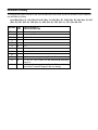
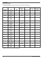
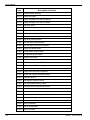
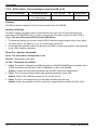
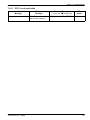
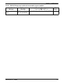
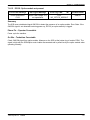
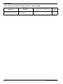
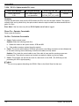
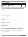
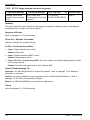
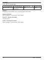
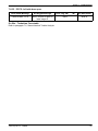
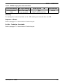
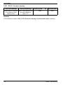
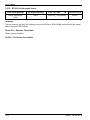
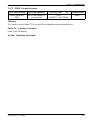
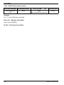
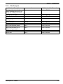
Revision History
The original issue and revisions of the Service Manual for the Kodak DryView 8700/8500 LASER IMAGER
are identified as follows:
Issue Date (Rev. A): 1/96, (Rev. B): 4/96, (Rev. C): 9/96, (Rev. D): 12/96, (Rev. E): 3/96, (Rev. F): 5/97,
(Rev. G): 8/97, (Rev. H): 7/98, (Rev. J): 4/99, (Rev. K): 3/00, (Rev. L): 3/01, (Rev. M): 5/01
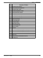
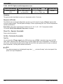
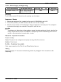
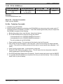
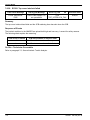
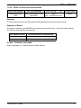
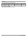
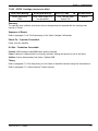
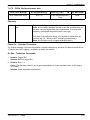
Section
Title/a
Text
Rev.
M
Warnings L
Pages Changed in
Current Revision (M)
Title and a pages
–
TOC
M
xi, xiii, xviii
1
L
–
2
L
–
3
M
3-21
4
L
–
5
M
5-1, -4, -6, -7
6
L
–
7
M
7-1, this section was previously Section 8.
8
M
9
M
8-1, -30, -31, -44, -61 thru -65, this section was previously
Section 9.
9-1, this section was previously Section 7, the revision
level of the Functional Diagrams did not change.
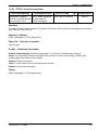
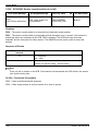
Warnings and Cautions
Warnings and Cautions for Kodak DryView 8700/8500 LASER IMAGER
Safety Instructions
Read and understand all instructions before using.
!
WARNING
This equipment is operated with hazardous voltage which can shock, burn, or cause
death.
Remove wall plug before servicing equipment. Never pull on cord to remove from outlet. Grasp plug and
pull to disconnect.
Do not operate equipment with a damaged power cord.
Do not use an extension cord to power this equipment.
Position the power cord so it will not be tripped over or pulled.
Connect this equipment to a grounded outlet.
Use only the power cord supplied with this equipment.
Do not place a portable multiple–socket outlet (power strip) on the floor. Mount the power strip on a wall or
on the underside of a table.
!
WARNING
Not protected against ingress of liquids including bodily fluids.
!
WARNING
For continued protection against fire, replace fuses only with fuses of the same type and rating.
!
WARNING
This equipment contains moving parts that may be accessible to the user. Loose clothing, jewelry, or long
hair may cause minor personal injury or damage to the equipment. Do not operate equipment with the
covers open. Do not operate equipment with any of the safety interlocks overridden.
!
WARNING
This equipment is not contained in a sealed cabinet. Therefore, it must not be used in locations where it
can come in contact with liquids, including bodily fluids.
!
CAUTION
Do not use in the presence of flammable anesthetics, oxygen or nitrous oxide. This equipment does not
have a gas-sealed electronics enclosure and could ignite any flammable or explosive gases present in its
environment.
2001 March Rev. L
1202688
i
Service Manual
!
CAUTION
This equipment has been tested and found to comply with the limits for a Class B digital device, pursuant
to part 15 of the FCC rules. Those limits are designed to provide reasonable protection against harmful
interference in a residential installation. This equipment generates, uses, and can radiate radio frequency
energy and, if not installed and used in accordance with the instructions, may cause harmful interference
to radio communications. However, there is no guarantee that interference will not occur in a particular
installation. If this equipment does cause harmful interference to radio or television reception, which can
be determined by turning the equipment off and on, the user is encouraged to try to correct the
interference by one or more of the following measures:
•
Reorient or relocate the receiving antenna.
•
Increase the separation between the equipment and the receiver.
•
Connect the equipment into an outlet on a circuit different from that to which the receiver is connected.
•
Consult the dealer or an experienced radio/TV technician for help.
•
FCC ID: PA4870085007E2620
!
CAUTION
Avoid Laser Beam
This equipment employs a 150 milliwatt laser. Laser radiation may be present when the
machine operates without panels or covers installed.
Use of controls or adjustments, or performance of procedures other than those specified herein, may
result in eye damage.
Covers shall be removed by authorized service personnel only.
!
CAUTION
This equipment is intended to connect to other medical devices. Only qualified service personnel may
perform installation and service maintenance. The laser in the equipment is not a patient device.
Therefore, the equipment must be installed no closer than 1.83 meters from a patient bed or chair.
!
CAUTION
U.S. Federal law restricts this device to the sale by, or on the order of, a licensed health care practitioner.
!
CAUTION
Do not substitute or modify any part of this equipment without approval of Eastman Kodak Company.
!
CAUTION
General External Cleaning: This equipment may be cleaned with a damp cloth using water with mild
detergent, or commercial electronic equipment cleaner.
ii
1202688
2001 March Rev. L
Warnings and Cautions
Do not touch, Hot Surface!
ATTENTION:
Surface Chaude. Ne pas toucher!
CAUTION:
Do not touch. Hot surface!
ACHTUNG:
Nicht anfassen. Heisse Oberflache!
ADVERTENCIA:
No tocar. Superficia Caliente!
ATTENZIONE:
Non toccare. Superficie Calda!
OPGEPAST:
Niet aanraken. Heet Oppervlak!
Class 1 Laser
Laser de catégorie 1
Laser-Klasse 1
Laser di Classe 1
Klass 1 Laser
Left
Front
DANGER
2001 March Rev. L
1202688
-
Rear
Invisible Laser Radiation When Open.
Avoid Direct Exposure to Beam.
ATTENTION -
Rayonnement Laser Invisible En Cas
D’Ouverture. Exposition Dangereuse
Au Faisceau.
VORSICHT
-
Unsichtbare Laserstrahlung Wenn Abdeckung
Geöffnet. Nicht Dem Strahl Aussetzen.
VARNING
-
Osynlig Laserstrålning. Laserstråining När
Denna Del Ä Öppnad. Strålen Är Farlig.
iii
Service Manual
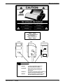
Label located on back of IMAGER.
iv
1202688
2001 March Rev. L
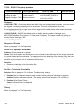
Warnings and Cautions for External Interface Box Accessories
Warnings and Cautions for
External Interface Box Accessories
Read and understand all instructions before using.
Classifications
UL Classified
File Number E183646
Control Number 9R46
Medical Equipment
UL 2601-1
CAN/CSA No. 601.1
!
Classified by Underwriters Laboratories Inc. With Respect to Electric Shock, Fire, Casualty and
Medical Hazards only in Accordance with UL 2601-1, CAN/CSA C22.2 No. 601.1 and IEC 601.1.
!
CAUTION
Do not use in the presence of flammable anesthetics, oxygen or nitrous oxide. This equipment does not
have a gas sealed electronics enclosure and could ignite any flammable or explosive gases present in its
environment.
!
WARNING
This equipment is operated with hazardous voltage which can shock, burn, or cause
death.
Remove wall plug before servicing equipment. Never pull on cord to remove from outlet. Grasp plug and
pull to disconnect.
Do not operate equipment with a damaged power cord.
Do not use an extension cord to power this equipment.
Position the power cord so it will not be tripped over or pulled.
Connect this equipment to a grounded outlet.
Use only the power cord supplied with this equipment.
Do not place a portable multiple–socket outlet (power strip) on the floor. Mount the power strip on a wall or
on the underside of a table.
2001 March Rev. L
1202688
v
Service Manual
!
WARNING
Not protected against ingress of liquids, including bodily fluids.
!
WARNING
For continued protection against fire, replace fuses only with fuses of the same type and fuse rating.
!
WARNING
This equipment is not contained in a sealed cabinet. Therefore, it must not be used in locations where it
can come in contact with liquids, including bodily fluids.
!
CAUTION
This equipment is intended to connect to other medical devices. Only qualified service personnel may
perform installation and service maintenance.
!
CAUTION
U.S. Federal law restricts this device to the sale by, or on the order of, a licensed health care practitioner.
!
CAUTION
Do not substitute or modify any part of this equipment without approval of Eastman Kodak Company.
!
CAUTION
This equipment has been tested and found to comply with the limits for a Class B digital device, pursuant
to part 15 of the FCC rules. Those limits are designed to provide reasonable protection against harmful
interference in a residential installation. This equipment generates, uses, and can radiate radio frequency
energy and, if not installed and used in accordance with the instructions, may cause harmful interference
to radio communications. However, there is no guarantee that interference will not occur in a particular
installation. If this equipment does cause harmful interference to radio or television reception, which can
be determined by turning the equipment off and on, the user is encouraged to try to correct the
interference by one or more of the following measures:
•
Reorient or relocate the receiving antenna.
•
Increase the separation between the equipment and the receiver.
•
Connect the equipment into an outlet on a circuit different from that to which the receiver is connected.
•
Consult the dealer or an experienced radio/TV technician for help.
!
CAUTION
General External Cleaning: This equipment may be cleaned with a damp cloth using water with mild
detergent, or commercial electronic equipment cleaner.
Type B Applied Part
vi
1202688
2001 March Rev. L
Agency, Regulatory and CE Marking Compliance
Agency, Regulatory and CE Marking Compliance
All agency, regulatory and CE marking information may be found in the User Guide for these models.
2001 March Rev. L
1202688
vii
Service Manual
BLANK PAGE
viii
1202688
2001 March Rev. L
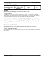
Section 1 – Specifications
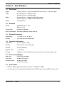
Section 1 – Specifications
1-1.
Dimensions
Height:
1279 mm (50.4 in.) – Top Cover closed 1641 mm (64.6 in.) – Top Cover open
Width:
661 mm (26.0 in.) – Left Door closed
1218 mm (47.9 in.) – Left Door open
Depth:
813 mm (32.0 in.) – Supply and Filter Doors closed
1392 mm (54.9 in.) – Supply and Filter Doors open
Weight:
250 kg (550 lbs)
1-2.
Electrical
Voltage:
200/220/240 VAC " 10%
50/60 Hz " 3%
Current Draw:
9 Amperes (maximum)
Power Consumption: 1800 watts (maximum) during warm up
1-3.
Storage Environment
Temperature:
–35° to 60°C (–31° to 140°F)
Humidity:
10% to 90% RH, Noncondensing
1-4.
Operating Environment
Temperature:
15° to 35°C (59° to 95°F)
Humidity:
20% to 85% RH, Noncondensing
Vibration:
0.01 Gs (maximum)
Magnetic Field:
v 100 Gauss
Leveling:
2 degrees or 3/4 inch difference maximum from front to back and side to side
1-5.
Environmental Effects
Heat Load:
2300 BTU/Hr (average)
Floor Load:
200 lb/ft2 (976 kg/m2)
Acoustical Noise:
55 dB at one meter
(70 dB momentarily)
1-6.
Host Control
•
RS232 or RS422 (jumper selectable) connection to IMAGER or UKEIB.
•
Can be located up to one kilometer (3280 feet) from IMAGER when using a UKEIB and fiber cable.
2001 March Rev. L
1202688
1-1
Service Manual
1-7.
Keypad
•
Available image formats include 1:1, 2:1, 4:1, 6:1, 9:1, 12:1, 15:1, 16:1, and 20:1, as well as up to
4 custom formats (for custom formats, images in the same row must all be the same format).
•
Images can be acquired and stored in random or sequential order.
•
Can be located up to one kilometer (3280 feet) from IMAGER (fiber cable).
1-8.
Cables
•
Keypad:
Not plenum rated
3 m (10 ft.), 10 m (33 ft.)
30 m (98 ft.), 60 m (197 ft.)
•
RS232:
Supplied by OEM
Not plenum rated
15 ft.
•
Digital:
Plenum rated
3 m (10 ft.), 10 m (33 ft.)
30 m (98 ft.), 60 m (197 ft.)
•
Analog:
Plenum rated
3 m (10 ft.), 10 m (33 ft.)
30 m (98 ft.), 60 m (197 ft.)
•
Fiber Optic:
Plenum rated
3 m (10 ft.), 10 m (33 ft.)
30 m (98 ft.), 60 m (197 ft.)
100 m (330 ft.), 150 m (490 ft.)
200 m (653 ft.), 250 m (816 ft.)
300 m (1090 ft.), 500 m (1652 ft.)
•
Characteristics:
Fiber (glass):
62./125 µm
Bandwidth:
160 MHz/km
Attenuation
< 4 db/km at 850 nm
Test attenuation per FOTP 171 S–T Connector
1-2
1202688
2001 March Rev. L
Section 2 – Installation
Section 2 – Installation
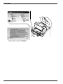
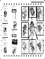
2-1.
Unpacking
Note
Steps 1 through 7 of this procedure can be performed by dock personnel or a Kodak-trained
technician. Steps 8 through 32 must be performed by a Kodak-trained technician.
Note
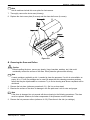
Refer to Figure 2-1 while performing steps 1 through 7 of this procedure.
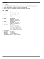
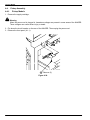
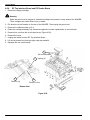
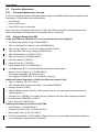
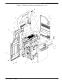
1. Remove the accessories box from the top of the shipping crate.
2. Remove the wire clamps that secure the front panel of the shipping crate, then remove the front panel.
3. Install the front panel as a ramp:
a. Lay the front panel down in front of the crate.
b. Unfold the small ramp at the top end of the front panel.
c. Set the bottom end of the front panel on the front edge of the crate. Align the holes in the panel
with the holes in the crate.
d. Use the two bolts stored underneath the IMAGER to secure the ramp to the crate.
4. Remove the foam packing from the front and top of the IMAGER.
5. Grasp the tape handle on the front of the IMAGER. Slowly pull the IMAGER out of the crate and ease
it down the ramp.
6. Remove the filter from the crate.
7. Roll the IMAGER to the installation location.
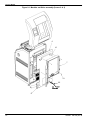
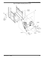
Accessories Box
Foam Packing
Plastic Bag
Foam Packing
Ramp Bolts
Tape Handle
Figure 2-1.
2001 March Rev. L
1202688
2-1
Service Manual
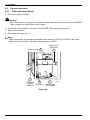
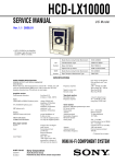
Note
The remaining steps of this procedure must be performed by a Kodak-trained technician.
8. Remove the plastic bag from the IMAGER.
9. Remove the power cord, warranty, User Guide, and installation kit from the exit tray.
10. Remove all the filament tape from the exterior of the IMAGER.
11. Remove the plastic sheet from the local panel.
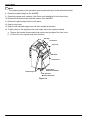
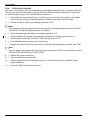
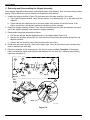
12. Open the top cover.
13. Open the left side and supply doors via their mechanical releases.
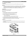
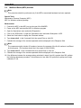
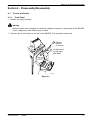
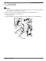
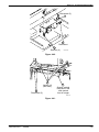
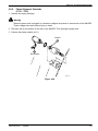
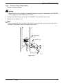
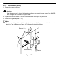
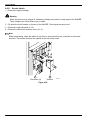
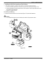
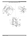
14. To gain access to the shipping screw on the right side of the exposure module:
a. Remove the bracket (three screws) that secures the top edge of the front cover.
b. Lift the front cover up and away from the frame.
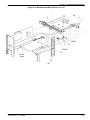
Exit Tray
Local Panel
Top Cover
Bracket
Front Cover
Filament Tape
Supply Door
Mechanical Release
Left Side Door
Mechanical Release
Figure 2-2.
2-2
1202688
2001 March Rev. L
Section 2 – Installation
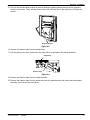
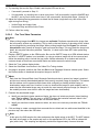
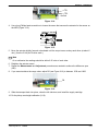
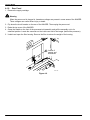
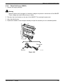
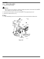
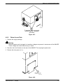
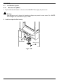
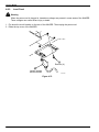
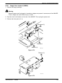
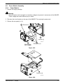
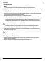
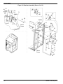
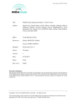
15. Use a 4 mm ball-end Allen wrench to remove the three shipping screws that secure the exposure
module to the frame. There are two screws on the left side and one on the right (front). Discard the
screws.
Shipping Screws
Figure 2-3.
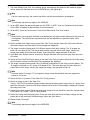
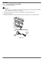
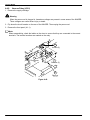
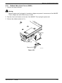
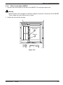
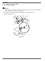
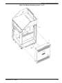
16. Remove the filament tape from the pickup arms.
17. Pull the pickup arms down and remove the foam block located above the pickup assembly.
Foam Block
Filament Tape
Figure 2-4.
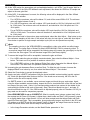
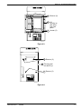
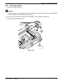
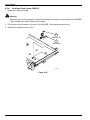
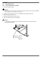
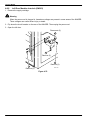
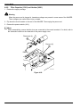
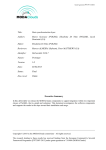
18. Remove the filament tape from the rollback handle.
19. Remove the filament tape from the wood block that is located between the frame and the transport
assembly, then remove the wood block.
2001 March Rev. L
1202688
2-3
Service Manual
Rollback Handle
Filament Tape
Wood Block
Figure 2-5.
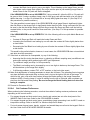
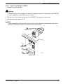
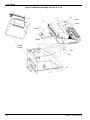
20. Remove the yellow caution tag from the handle on the transport assembly.
21. Release the processor latch and slide it to the right.
22. Grasp the handle on the front of the processor/exit assembly and pull the assembly out to its
extended position.
23. Remove the filament tape from both ends of the processor cover.
Filament Tape
(Both Ends)
Handle
Processor Latch
Figure 2-6.
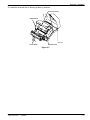
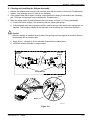
24. Open the processor cover.
25. Remove the tape from the foam sheet that is wrapped around the drum, then slowly pull the foam
sheet out of the processor.
26. Close the processor cover by lifting the cover slightly and pulling the support arm forward.
27. Press the blue release lever on the right side of the processor, then slide the processor/exit assembly
back into place.
28. Slide the processor latch to the left to secure the processor/exit assembly.
29. Install the front cover and bracket.
30. Close the supply door and left side door.
31. Close the top cover by lifting the cover slightly and pushing the support rod backward.
2-4
1202688
2001 March Rev. L
Section 2 – Installation
32. Install the charcoal filter in housing at back of machine.
Processor Cover
Support Arm
8700-113C
Foam Sheet
Release Lever
Figure 2-7.
2001 March Rev. L
1202688
2-5
Service Manual
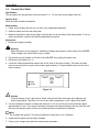
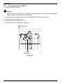
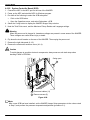
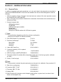
2-2.
!
Voltage Setup
Caution
The IMAGER can be configured to connect with 200, 220, or 240 VAC power sources. Before
applying power, ensure that the IMAGER is set for the voltage that most closely matches the AC
line voltage.
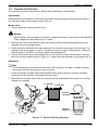
1. Measure the AC voltage at the wall outlet.
2. Remove the tag from the handle of the power module at the rear of the IMAGER. The tag indicates
the factory set voltage. If this setting does not match the line voltage, perform the remaining steps of
this procedure.
!
Warning
When the power cord is plugged in, hazardous voltages are present in some areas of the IMAGER.
These voltages can cause severe injury or death.
3. Flip down the circuit breaker on the rear of the IMAGER, then unplug the power cord.
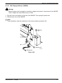
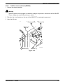
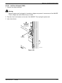
4. Remove the ventilation plate from the upper left corner of the power module (to gain access to the
terminal block above the transformer). Refer to Figure 2-8.
5. Move the black wire to the terminal that most closely matches the AC line voltage.
6. Replace the ventilation plate.
240
220
200
0
Figure 2-8.
2-6
1202688
2001 March Rev. L
Section 2 – Installation
2-3.
Cable Connections
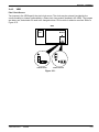
2-3-1.
Compact Keypad to TDB/C
Note
The compact keypad is no longer available, but may still be on site in some customer locations.
1. If a keypad extension cable is being used, connect it to the compactkeypad cable. Refer to Figure 2-9.
2. Connect the keypad cable (or keypad extension cable) to the TDB/C at the rear of the IMAGER. Refer
to Figure 2-9.
TDB/C
....
....
.
COMM 0
Keypad
Cable
....
....
.
COMM 1
Keypad
Extension
Cable
Compact
Keypad
Figure 2-9.
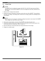
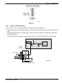
2-3-2.
Touch-Screen Keypad to KFEIB to TDB/F
Note
The KFEIB (Keypad/Fiber External Interface Box) only supports touch-screen keypad users. A
UKEIB is required for host control users.
1. Connect the keypad cable to the keypad and the KFEIB. Refer to Figure 2-10.
KFEIB
FIBER OPTIC
XMT
FTSW
A-CH
B-CH
KEYPAD
.........
.........
........ .
RCV
Keypad Cable
Keypad
Figure 2-10.
2001 March Rev. L
1202688
2-7
Service Manual
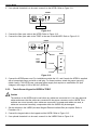
2. If an optional footswitch is to be used, connect it to the KFEIB. Refer to Figure 2-11.
KFEIB
FIBER OPTIC
XMT
FTSW
A-CH
KEYPAD
.........
.........
........ .
B-CH
RCV
Footswitch
Figure 2-11.
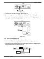
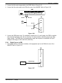
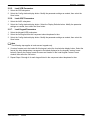
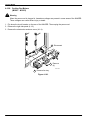
3. Connect the fiber optic cable to the KFEIB. Refer to Figure 2-12.
4. Connect the fiber optic cable to the TDB/F at the rear of the IMAGER. Refer to Figure 2-12.
KFEIB
FIBER OPTIC
XMT
FTSW
A-CH
KEYPAD
.........
.........
........ .
B-CH
RCV
A-Lead
TDB/F
B1
COMM 1
A1
Fiber
Optic
Cable
B-Lead
A-Lead
B0
COMM 0
A0
B-Lead
Figure 2-12.
5. Connect the KFEIB power cord. For installations outside the U.S. and Canada, the KFEIB is supplied
with a harmonized power cord with no wall plug. For these locations, attach the proper type plug
(obtain locally). The KFEIB uses a universal power supply that requires no modification for input
voltages in the range of 100 to 240 VAC (50/60 Hz).
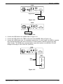
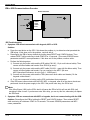
2-3-3.
!
Touch-Screen Keypad to UKEIB to TDB/C
Caution
The switches in the UKEIB must be set before any cables are connected to it. Use only approved
cables and ensure that the cables are connected to the proper connectors on the UKEIB. If the
switches are not set correctly when cables are connected, or unapproved cables are used, or
cables are connected incorrectly, components within the UKEIB may be damaged.
1. Set the switches in the UKEIB (Universal Keypad External Interface Box) as required. Refer to
Procedure 2-4-1.
2. Connect the keypad cable to the keypad and the UKEIB. Refer to Figure 2-13.
3. If an optional footswitch is to be used, connect it to the UKEIB. Refer to Figure 2-14.
2-8
1202688
2001 March Rev. L
Section 2 – Installation
UKEIB
FIBER OPTIC
HOST
.....
....
.....
....
XMT
FTSW
A-CH
IMAGER
B-CH
KEYPAD
.........
.........
........ .
RCV
Keypad Cable
Keypad
Figure 2-13.
UKEIB
FIBER OPTIC
XMT
FTSW
A-CH
B-CH
HOST
.....
....
IMAGER
.....
....
KEYPAD
.........
.........
........ .
RCV
Footswitch
Figure 2-14.
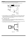
4. Connect the KEIB cable to the UKEIB. Refer to Figure 2-15.
5. Connect the KEIB cable to the TDB/C at the rear of the IMAGER. Refer to Figure 2-15.
6. Connect the UKEIB power cord. For installations outside the U.S. and Canada, the UKEIB is supplied
with a harmonized power cord with no wall plug. For these locations, attach the proper type plug
(obtain locally). The UKEIB uses a universal power supply that requires no modification for input
voltages in the range of 100 to 240 VAC (50/60 Hz).
UKEIB
FIBER OPTIC
XMT
FTSW
A-CH
B-CH
HOST
.....
....
IMAGER
.....
....
KEYPAD
.........
.........
........ .
RCV
TDB/C
....
....
.
COMM 1
....
....
.
COMM 0
KEIB
Cable
Figure 2-15.
2001 March Rev. L
1202688
2-9
Service Manual
2-3-4.
!
Host Control to UKEIB to TDB/F
Caution
The switches in the UKEIB must be set before any cables are connected to it. Use only approved
cables and ensure that the cables are connected to the proper connectors on the UKEIB. If the
switches are not set correctly when cables are connected, or unapproved cables are used, or
cables are connected incorrectly, components within the UKEIB may be damaged.
Note
Refer to subsection 5-4 for pinouts of the various host adapter cables.
Note
A translator keypad is required for hosts programmed with OEM commands other than Siemens. The
translator keypad translates the OEM commands to Kodak commands that can be interpreted by the
IMAGER. Different translator keypads are required for different OEMs.
A Siemens’ SHPT is not required for the IMAGER. The TDB translates the Siemens commands. For
setup instructions refer to the MPC for Windows Comm parameters.
1. Set the switches in the UKEIB (Universal Keypad External Interface Box) as required. Refer to
Procedure 2-4-1.
2. Connect the host adapter cable to the UKEIB. Refer to Figure 2-16.
Host
Host Adapter Cable
UKEIB
FIBER OPTIC
XMT
FTSW
A-CH
B-CH
HOST
.....
....
IMAGER
.....
....
KEYPAD
.........
.........
........ .
RCV
Keypad Cable
Translator
Keypad
Figure 2-16.
3. If a translator keypad is required, connect the keypad cable to the keypad and the UKEIB. Refer to
Figure 2-16.
4. If an optional footswitch is to be used, connect it to the UKEIB. Refer to Figure 2-17.
2-10
1202688
2001 March Rev. L
Section 2 – Installation
UKEIB
FIBER OPTIC
HOST
.....
....
.....
....
XMT
FTSW
A-CH
IMAGER
B-CH
KEYPAD
.........
.........
........ .
RCV
Footswitch
Figure 2-17.
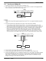
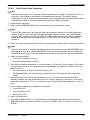
5. Connect the fiber optic cable to the UKEIB. Refer to Figure 2-18.
6. Connect the fiber optic cable to the TDB/F at the rear of the IMAGER. Refer to Figure 2-18.
7. Connect the UKEIB power cord. For installations outside the U.S. and Canada, the UKEIB is supplied
with a harmonized power cord with no wall plug. For these locations, attach the proper type plug
(obtain locally). The UKEIB uses a universal power supply that requires no modification for input
voltages in the range of 100 to 240 VAC (50/60 Hz).
UKEIB
FIBER OPTIC
HOST
.....
....
.....
....
XMT
FTSW
A-CH
KEYPAD
.........
.........
........ .
IMAGER
B-CH
RCV
A-Lead
TDB/F
B-Lead
B1
COMM 1
A1
Fiber
Optic
Cable
A-Lead
B0
COMM 0
A0
B-Lead
Figure 2-18.
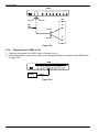
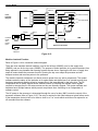
2-3-5.
Video Source to VEIB to FIB
1. Check/set the jumpers in the VEIB. Refer to Procedure 2-4-3.
2. Use an analog cable to connect the video signal from the modality to the appropriate Video In
connector on the VEIB. Refer to Figure 2-19.
3. If the modality provides a pixel clock signal, use an analog cable to connect it to the appropriate Ext
Clock In connector on the VEIB. Refer to Figure 2-19.
VEIB
PORT 0
VIDEO VIDEO
IN
OUT
FIBER OPTICS
A-CH
B-CH
PORT 1
VIDEO VIDEO
OUT
IN
EXT CLOCK IN
PORT 0 PORT 1
Video
Modality
Pixel Clock
Figure 2-19.
2001 March Rev. L
1202688
2-11
Service Manual
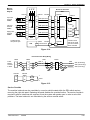
4. Connect the fiber optic image cable to the VEIB. Refer to Figure 2-20.
5. Connect the fiber optic cable to the FIB at the rear of the IMAGER. Refer to Figure 2-20.
VEIB
PORT 0
VIDEO VIDEO
IN
OUT
FIBER OPTICS
A-CH
B-CH
A-Lead
PORT 1
VIDEO VIDEO
OUT
IN
EXT CLOCK IN
PORT 0 PORT 1
FIB
B-Lead
A1
A0
Fiber
Optic
Cable
A-Lead
B1
B-Lead
B0
Figure 2-20.
6. Connect the VEIB power cord. For installations outside the U.S. and Canada, the VEIB is supplied
with a harmonized power cord with no wall plug. For these locations, attach the proper type plug
(obtain locally). The VEIB uses a universal power supply that requires no modification for input
voltages in the range of 100 to 240 VAC (50/60 Hz).
2-3-6.
Video Source to VIB
1. Use an analog cable to connect the video signal from the modality to the appropriate Video In
connector on the VIB at the rear of the IMAGER. Run the analog cable through the ferrite core as
shown on the machine label. Refer to Figure 2-21.
2. If the modality provides a pixel clock signal, use an analog cable to connect it to the appropriate Ext
Clock In connector on the VIB at the rear of the IMAGER. Refer to Figure 2-21.
VIB
PORT 0
VIDEO VIDEO
IN
OUT
Modality
Pixel Clock
PORT 1
VIDEO VIDEO
IN
OUT
Video
EXT CLOCK IN
PORT 0 PORT 1
Figure 2-21.
2-12
1202688
2001 March Rev. L
Section 2 – Installation
2-3-7.
Video Source to EVEIB to FIB
1. Check/set the jumpers in the EVEIB. Refer to Procedure 2-4-5.
2. If the modality provides a pixel clock signal, use an analog cable to connect it to the appropriate Ext
Clock In connector on the EVEIB. Refer to Figure 2-22.
EVEIB
Fiber Optics
A-Ch B-Ch
Port 0
H–Sync Video Video
V–Sync Composite
IN
OUT
Port 1
Video Video
OUT
IN
Ext Clock IN
Port-0
Port-1
Video
Modality
Pixel Clock
Figure 2-22.
Note
Port 0 is the only port that supports separate Sync inputs. Port 1 only supports standard composite
video.
3. The video connections vary depending on the type of video output by the modality:
•
If the modality provides standard composite video, use an analog cable to connect the video
signal from the modality to the appropriate Video In connector on the EVEIB. Refer to Figure 2-22.
•
If the modality provides SVGA output (like the PowerPC), an adaptor cable is required. Refer to
Figure 2-23. Connect the green BNC cable to the Video In Port 0 connector on the EVEIB.
Connect the black BNC cable to the H-Sync/Composite connector. If the modality provides a
separate vertical sync signal, connect the yellow BNC cable to the V-Sync connector. The two
15-pin connectors on the adapter cable connect to the PC (longer cable) and the monitor cable.
EVEIB
Fiber Optics
A-Ch B-Ch
Port 0
H–Sync Video Video
V–Sync Composite
IN
OUT
Yellow
Black
Port 1
Video Video
OUT
IN
Ext Clock IN
Port-0
Port-1
Green
Monitor
PC
Figure 2-23.
4. Connect the fiber optic image cable to the EVEIB. Refer to Figure 2-24.
5. Connect the fiber optic cable to the FIB at the rear of the IMAGER. Refer to Figure 2-24.
6. Connect the EVEIB power cord. For installations outside the U.S. and Canada, the EVEIB is supplied
with a harmonized power cord with no wall plug. For these locations, attach the proper type plug
(obtain locally). The EVEIB uses a universal power supply that requires no modification for input
voltages in the range of 100 to 240 VAC (50/60 Hz).
2001 March Rev. L
1202688
2-13
Service Manual
EVEIB
Port 0
H–Sync Video Video
V–Sync Composite
IN
OUT
Fiber Optics
A-Ch B-Ch
A-Lead
Port 1
Video Video
OUT
IN
Ext Clock IN
Port-0
Port-1
FIB
B-Lead
A1
A0
Fiber
Optic
Cable
A-Lead
B1
B-Lead
B0
Figure 2-24.
2-3-8.
Digital Source to DEIB to FIB
1. Check/set the jumpers in the DEIB. Refer to Procedure 2-4-6.
2. Use a digital cable to connect the modality to the appropriate Digital In connector on the DEIB. Refer
to Figure 2-25.
DEIB
FIBER OPTICS
A-CH B-CH
Modality
DIGITAL IN
PORT 0
...................
..................
PORT 1
...................
..................
Digital
Image
Figure 2-25.
2-14
1202688
2001 March Rev. L
Section 2 – Installation
3. Connect the fiber optic image cable to the DEIB. Refer to Figure 2-26.
4. Connect the fiber optic cable to the FIB at the rear of the IMAGER. Refer to Figure 2-26.
DEIB
FIBER OPTICS
A-CH B-CH
A-Lead
B-Lead
PORT 1
...................
..................
FIB
A1
A0
Fiber
Optic
Cable
DIGITAL IN
PORT 0
...................
..................
A-Lead
B1
B-Lead
B0
Figure 2-26.
5. Connect the DEIB power cord. For installations outside the U.S. and Canada, the DEIB is supplied
with a harmonized power cord with no wall plug. For these locations, attach the proper type plug
(obtain locally). The DEIB uses a universal power supply that requires no modification for input
voltages in the range of 100 to 240 VAC (50/60 Hz).
2-3-9.
Digital Source to DIB
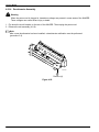
1. Use a digital cable to connect the modality to the appropriate port on the DIB at the rear of the
IMAGER. Refer to Figure 2-27.
DIB
PORT 1
Digital Image
PORT 0
Modality
Figure 2-27.
2001 March Rev. L
1202688
2-15
Service Manual
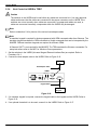
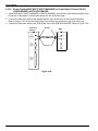
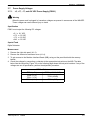
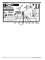
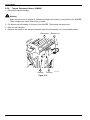
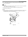
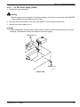
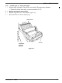
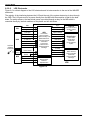
2-3-10. Kodak DryView 8800 MULTI-INPUT MANAGER or Kodak Digital Science 969 HQ
LASER IMAGER to 8700/8500 IMAGER
1. At the 8800 MULTI-INPUT MANAGER or 969 HQ IMAGER, route the fiber optic cable through the slot
at the rear of the cabinet. Pull the cable across the top of the card cage.
2. Connect the fiber optic cable to the appropriate fiber optic connectors on the local fiber interface.
Refer to Figure 2-28. Secure the cable using the hook and loop material on top of the card cage.
3. Connect the fiber optic cable to the DPRI at the rear of the 8700/8500 IMAGER. Refer to Figure 2-28.
Local Fiber
Interface
CH-B
REMOTE
PRINTER
0
CH-A
PROC
OUTPUT
MODULE
0
B-Lead
DPRI
Fiber Optic Cable
CH-B
CH-A
A-Lead
PRINTER
OUTPUT
MODULE
0
Figure 2-28.
2-16
1202688
2001 March Rev. L
Section 2 – Installation
2-4.
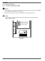
Switch and Jumper Settings
2-4-1.
!
!
UKEIB
Caution
The switches in the UKEIB must be set before any cables are connected to it. If the switches are
not set correctly when cables are connected, components within the UKEIB may be damaged.
Caution
Use only approved cables and ensure that the cables are connected to the proper connectors on
the UKEIB. If unapproved cables are used, or cables are connected incorrectly, components within
the UKEIB may be damaged.
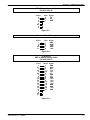
Note
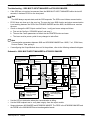
Refer to Figure 2-29 (on the following page) for switch locations.
Signal Path
SW1 determines which signal path is enabled within the UKEIB. The various control sources require
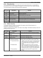
different signal paths. Set the switches as indicated in the table on the following page.
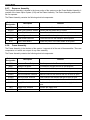
Host Connector Signals
SW2 determines which signals will be present on Pins 5 and 9 of the HOST connector. For normal
operation, set SW2 to the center position. If an OEM fiber optic kit is being installed, set SW2 as directed
in the kit instructions.
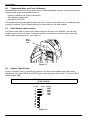
Signal Path Enabled
SW1 Switch Positions
1
2
3
4
5
6
Keypad to TDB
On
Off
On
On
On
On
RS232 Host to TDB
Off
On
Off
Off
On
Off
RS422 Host to TDB
Off
On
Off
On
On
On
RS232 Host to Translator Keypad to TDB
On
Off
On
Off
Off
On
RS422 Host to Translator Keypad to TDB
On
Off
On
On
On
On
HOST Connector (P3) Signals
SW2
Position
Pin 5
Pin 9
Left
5V
GND
Center
KP-IN
KP-OUT
Right
+12V
–12V
2001 March Rev. L
1202688
2-17
Service Manual
SW1
1 2 3 4 5 6
SW2
ON
FIBER OPTIC
HOST
XMT
FTSW
A-CH
B-CH
IMAGER
KEYPAD
RCV
Figure 2-29.
2-4-2.
Copper TDB
Jumpers W1 and W4
Jumpers W1 and W4 configure J1 and J2 for RS422 or RS232 input. W1 configures J1 (Comm 0) and W4
configures J2 (Comm 1). Set the jumper to the left for RS232 and to the right for RS422.
W4
SW2
J2 (Comm 1)
W1
SW1
J1 (Comm 0)
TDB/C
Figure 2-30.
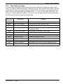
Switches SW1 and SW2
Switches SW1 and SW2 control which signals are routed to pins 5 and 9 of J1 and J2. SW1 controls J1
(Comm 0) and SW2 controls J2 (Comm 1). Each switch can be placed in one of three positions, as
described in the following table.
!
Caution
SW1 and SW2 must be set correctly. An incorrect setting could result in damage to the equipment
connected to the TDB, and/or blow fuses on the TDB.
Position
Pin 5
Pin 9
Left
+5V
GND
UKEIB, Genesis Cable, Kodak Fiber Optic Converter, other RS422 hosts.
Center
RTS
CTS
RS232 handshaking (RTS output, CTS input). Currently not used; may be
used in the future for Toshiba host control.
Right
+12V
–12V
Siemens external fiber optic converter, compact Keypad.
2-18
Used For
1202688
2001 March Rev. L
Section 2 – Installation
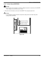
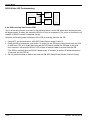
2-4-3.
VEIB
Pixel Clock Source
Two jumpers in the VEIB specify the pixel clock source. The clock may be external (provided by the
source modality) or internal (generated by a Phase Lock Loop module installed in the VEIB). The jumpers
are factory set, and should not need to be changed unless a PLL module is added or removed. Refer to
Figure 2-31.
VEIB
Main PWA
PLL
Module
PS
Internal Clock
External Clock
Figure 2-31.
2001 March Rev. L
1202688
2-19
Service Manual
2-4-4.
VIB
Pixel Clock Source
Two jumpers on the VIB specify the pixel clock source. For an internal clock (generated by a Phase Lock
Loop module installed on the VIB), set the jumpers to E1-E2 and E4-E5. For an external clock (provided
by the source modality), set the jumpers to E2-E3 and E5-E6. The jumpers are factory set, and should not
need to be changed unless a PLL module is added or removed. Refer to Figure 2-32.
Continuous Acquire Mode
When a jumper is connecting pins E7 and E8, the VIB operates in continuous acquire mode. This may be
useful when attempting to examine the source video signal. However, for normal operation the two pins
must not be connected (place the jumper block on a single pin; this is the factory setting).
VIB
:
...
E3
E2
E1
E6
E5
E4
E8 E7
...
Figure 2-32.
2-20
1202688
2001 March Rev. L
Section 2 – Installation
2-4-5.
EVEIB
Pixel Clock Source
Jumpers W5 and W6 specify the pixel clock source. The clock may be external (provided by the source
modality) or internal (generated by a Phase Lock Loop module installed in the EVEIB). The jumpers are
factory set, and should not need to be changed unless a PLL module is added or removed. Refer to
Figure 2-33.
Termination
Jumpers W1 through W4 determine whether or not the Video In and Sync ports are terminated at 75
ohms. For each port, if the jumper is installed, termination is provided. This is the default setting. The
jumper should only be removed if a T-connector is being used on the port. Refer to Figure 2-33.
Sync Detect Potentiometer
Jumper W8 determines whether or not the manual sync detect potentiometer (R6) is enabled. Refer to
Figure 2-33. By default, R6 is disabled. The following paragraphs describe the situation in which R6 might
need to be enabled.
The width of the horizontal sync pulse should be approximately 7.5% of the horizontal line time. It it is
significantly different (<5% or >10%), the EVEIB may not be able to detect horizontal or vertical sync. Two
modalities known to have this problem are the ADAC 4100 and the Toshiba X-Vision.
Before enabling R6 and performing a manual sync detect adjustment, be sure to try each of the 16
combinations of settings for Vertical Sync Detect and Black Level Window available in the Advanced
Video Parameters screen in MPC for Windows. Refer to the MPC help screens for details. If a manual
sync detect adjustment is required, refer to the EVEIB Installation Instructions.
When manual sync
detect adjustment is
required.
1
When manual sync detect adjustment is not
required (default setting).
W8
W7 (Not jumpered)
Without
PLL
Module
With PLL
Module
PS
Main PWA
PLL
Module
1
W5
W6
W3
V-Sync
W4
W1
H-Sync/Comp Video In
Port 0
With PLL Module
W2
Video In
Port 1
Without PLL Module
1
W1, W2, W3, W4: Jumper on = 75 ohm termination; Jumper off = High Z.
Figure 2-33.
2001 March Rev. L
1202688
2-21
Service Manual
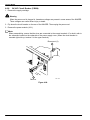
2-4-6.
DEIB
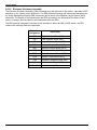
Transfer Clock Speed
Two jumpers in the DEIB specify either single (10 MHz) or dual (12.5 MHz) transfer clock speed.
When a DEIB is connected to the IMAGER, it must always be set for single (10 MHz) transfer clock
speed. This is the factory default setting.
DEIB
Main PWA
PS
Single Transfer
Clock Speed
Figure 2-34.
2-22
1202688
2001 March Rev. L
Section 2 – Installation
2-5.
System Configuration
After all cables have been connected, and all switch and jumper settings have been verified, perform the
following configuration procedures.
2-5-1.
!
Power Up the IMAGER
Caution
The IMAGER can be configured to connect with 200, 220, or 240 VAC power sources. Before
applying power, ensure that the IMAGER is set for the voltage that most closely matches the AC
line voltage. Refer to procedure 2-2.
1. Connect the power cord to the IMAGER and the wall outlet.
2. Flip up the circuit breaker at the rear of the IMAGER.
3. Turn on the IMAGER.
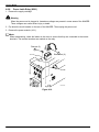
2-5-2.
Connect the MPC to the IMAGER
1. Connect a straight-through serial cable (9-pin female to 9-pin male) between the serial port of the
MPC and the MPC connector at the rear of the IMAGER.
2. Install a hardlock key on the printer port of the MPC.
3. Turn on the MPC, and start the MPC for Windows program.
Note
If a “Subsystem Not Communicating” message is displayed, select Preferences from the Operations
menu, then check the Direct Connect Baud and Com settings.
MPC
Connector
Figure 2-35.
2001 March Rev. L
1202688
2-23
Service Manual
Note
The MPC for Windows program is used to load configuration parameters into NVRAM within the
various system components. Context sensitive help is available throughout the program via the F1
key. For example, for a description of a particular parameter, move the highlight to that parameter,
then press F1. The MPC for Windows Help file will open and display the topic associated with the
highlighted parameter.
2-5-3.
Set the System Clock
1. Select Clock from the Utilities menu.
2. Enter the date and time in the Clock window, then select the OK button.
2-5-4.
Load IMS Parameters
1. Select the IMS subsystem.
2. Select Output 0 Comm 0 from the component select dropdown list box (to the right of the subsystem
buttons).
3. Select the Comm window display button.
4. Select the Printer Defaults button, then select the Save button.
5. Select the first user from the component select dropdown list box.
Note
Users are identified by slot/comm (e.g., Input 1 Comm 0) or modality name, depending on the User
Display setting in the Preferences window.
6. If a script file is available for this user, select the Script window display button. Specify the script file
name and location in the Select Script File window, then select the OK button. If a script file is not
available, or the script file settings need to be modified, proceed to the next step.
7. Select the Comm window display button. Select the appropriate Defaults button, modify the parameter
settings as needed for host control users, then select the Save button.
8. Select the Image window display button. Modify the parameter settings as needed, then select the
Save button.
9. Select the Host window display button. Modify the parameter settings as needed, then select the Save
button.
10. Select the System window display button. Modify the parameter settings as needed, then select the
Save button.
11. If the system includes a second user, select the second user from the component select dropdown list
box. Repeat Steps 6 through 10.
12. After all the IMS parameters have been loaded, power cycle the IMAGER.
2-24
1202688
2001 March Rev. L
Section 2 – Installation
2-5-5.
Load SCB Parameters
1. Select the SCB subsystem.
2. Select the Config window display button. Modify the parameter settings as needed, then select the
Save button.
2-5-6.
Load AIQC Parameters
1. Select the AIQC subsystem.
2. Select the Config window display button. Select the Display Defaults button. Modify the parameter
settings as needed, then select the Save button.
2-5-7.
Load Keypad Parameters
1. Select the Keypad (KPD) subsystem.
2. Select the first keypad from the component select dropdown list box.
3. Select the Config window display button. Modify the parameter settings as needed, then select the
Save button.
Note
The following step applies to touch-screen keypads only.
4. If custom formats are to be loaded for this keypad, select the Load window display button. Select the
format (the letter designations correspond to the labels displayed on the keypad’s custom format
buttons). Specify the custom format file name and location in the Load Keypad Custom Format
window, then select the OK button.
5. Repeat Steps 2 through 4 for each keypad listed in the component select dropdown list box.
2001 March Rev. L
1202688
2-25
Service Manual
2-5-8.
Digital Modality Setup
Note
Load digital parameters from a script file whenever possible (refer to Step 6 of Procedure 2-5-4). If a
script file is not available for the modality, enter parameters manually. To determine the correct
settings, refer to the OEM specifications, contact the OEM site engineer, or contact the National
Service Center.
1. Select the EIB subsystem.
2. Select the first DEIB or DIB user from the component select dropdown list box.
3. Select the Config window display button. Modify the parameter settings as needed, then select the
Save button.
Note
When the Save button is selected, the digital parameters are loaded into the DEIB or DIB. If the save
operation fails (when using a DEIB), check the fiber optic cables (use a flashlight), the DEIB power
supply, and input module communications (use MPC for WIndows diagnostics).
4. Verify that the modality is generating an image.
5. Select the Acquire button.
Note
If the acquire fails, recheck the digital parameter settings. Modify the settings as needed. Save the
new settings, then try to acquire again.
6. Select the Print button. Verify that the image is printed successfully.
2-5-9.
2-5-9-1.
Video Modality Setup
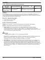
Inspect Signals from Modality
1. Verify that the modality is generating an image.
2. Inspect the video and pixel clock signals:
a. Check for two video modes. Check with the OEM to determine if the modality can operate in two
different modes that require different video parameters. Some OEMs have one set of video
parameters for Live (Scan) mode and another set for Review (Off Tape) mode. Set up for one or
the other.
b. Check for double termination. Observe the host monitor while connecting the video cable to a
powered up VEIB/VIB/EVEIB. If the monitor image improves or stays the same, there is no
problem. If the monitor image suddenly goes bad (ghosting, blurring, faint, etc.), the video signal
may already be terminated once, and connecting to the VEIB/VIB/EVEIB causes a double
termination problem. If so, resolve this problem before proceeding.
c. Check the pixel clock signal. Connect the pixel clock cable to the oscilloscope (do not terminate
the scope). The pixel clock signal must be above 0.5 volts peak to peak and must be stable. (A
pixel clock filter may help eliminate glitches in the pixel clock, but it may also make it worse!) If the
signal is okay, connect the pixel clock cable to the VEIB/VIB/EVEIB.
d. Avoid ground loops. To prevent a possible ground loop, connect the VEIB/EVEIB power cord to
the same power source as the OEM modality. If this cannot be done, and image noise problems
are experienced later during image fine tuning, check for a ground loop problem as follows:
Temporarily disconnect the ground wire from the VEIB/EVEIB. Run a ground wire from the
VEIB/EVEIB to the OEM ground. If the noise goes away, there is a ground loop problem.
2-26
1202688
2001 March Rev. L
Section 2 – Installation
2-5-9-2.
Enter Rough Video Parameters
Note
Load video parameters from a script file whenever possible (refer to Step 6 of Procedure 2-5-4). If a
script file is not available for the modality, enter parameters manually. This requires that an
oscilloscope be used to measure some parameters; other parameters are calculated based on these
measurements. Refer to the video parameter help screens in MPC for Windows.
1. Select the EIB subsystem.
2. Select the first VEIB/VIB/EVEIB user from the component select dropdown list box.
Note
If an EVEIB is being used, verify that the Video Input parameter setting (in the Video Parameters
window) is correct. Also verify that the Passes parameter setting is correct. (The EVEIB digitizes
incoming video slightly slower than the VEIB. The VEIB would sometimes work with the number of
passes set lower than the recommended setting, but the EVEIB will not acquire if the setting is
incorrect.)
3. Select the Config window display button. Enter rough parameter settings, then select the Save button.
Note
When the Save button is selected, the video parameters are loaded into the VEIB/VIB/EVEIB. If the
save operation fails (when using a VEIB/EVEIB), check the fiber optic cables (use a flashlight), the
VEIB/EVEIB power supply, and input module communications (use MPC for WIndows diagnostics).
4. Select the Acquire button.
•
If successful, proceed to Step 12.
•
If not successful, proceed to Step 5.
5. Temporarily set framing parameters to crop the image to a 100 line by 100 pixel square. (This is done
to ensure that a vertical or horizontal sync pulse is not sampled; the parameters will be set for a full
frame in Step 12.)
•
Set Image Lines to 100 and Horiz Active Pixels to 100.
•
Set Horizontal Delay and Vertical Delay to select this 100 x 100 square from the center of the
image.
6. Connect the host video cable to the oscilloscope (use a T connector with a 75 ohm terminator
attached). Measure the video signal from sync tip to maximum white level. If less than 1 volt, set the
Double Gain parameter to 0.5 to 1.0. If more than 1 volt, set the Double Gain parameter to 1.0 to 2.0
volts.
7. Set the following parameters to midpoints as indicated:
•
Clock Delay to 6.
•
Fine Pixel Delay to 180.
•
Black Level to 100.
8. Select the Save button.
9. Verify that the Enable LED is on. This indicates that the parameter set has been loaded and the
VEIB/VIB/EVEIB is in a ready state. Refer to Figure 2-36 (VEIB), Figure 2-37 (VIB), or Figure 2-38
(EVEIB).
2001 March Rev. L
1202688
2-27
Service Manual
VEIB
Main PWA
PS
Enable LED #11
Go LED #10
Acquire LED #1
Sync LED #9
LED #8
Port 0
Gain
Port 1
Gain
INSYNC
CONFIG
ACQUIRE
ENABLE
UNDFLW
OVRFLW
Figure 2-36.
oooooo
VIB
Figure 2-37.
2-28
1202688
2001 March Rev. L
Section 2 – Installation
EVEIB
PS
Main PWA
UNDER
OVER
ENABLE
CONFIG
AQU
SYNC
Figure 2-38.
Note
The following step refers to the gain pot in the VEIB. The VIB and EVEIB have no gain pots; they
adjust the gain automatically. With this exception, the following step applies to the VEIB and the
VIB/EVEIB.
10. Adjust the gain pot in the VEIB until the Sync LED turns on, then continue turning the pot in the same
direction for at least three full turns. Refer to Figure 2-36.
The Sync LED must stay on without flickering or acquires will fail! There must be at least three
full turns of the pot during which the Sync LED remains on steadily. If not, check the video amplitude.
The Double Gain parameter may need to be changed to the other setting.
When the Sync LED is on, it indicates that the VEIB/VIB/EVEIB sees the video signal, and is
successfully detecting horizontal and vertical sync pulses. The pixel clock has no effect on the state of
the Sync LED.
If the Sync LED does not turn on when the gain pot is turned (and the Enable LED is on), either
no video is present, or the video that is present is completely unrecognizable to the VEIB/VIB/EVEIB
(the VEIB/VIB/EVEIB cannot detect horizontal or vertical sync pulses.) In this case:
•
The video cable may be on the wrong port.
•
The video signal amplitude may be less than 0.5 volts (this could have several causes: double or
triple termination, bad cables, bad video, etc.).
•
The video signal amplitude may be okay, but the signal may be bad.
•
One or more of the following parameters may be set incorrectly: Double Gain, Black Level, and/or
Source.
2001 March Rev. L
1202688
2-29
Service Manual
11. Try acquiring (be sure the Sync, Enable, and Acquire LEDs are all on).
•
If successful, proceed to Step 12.
•
If unsuccessful, try acquiring two or three more times. If still unsuccessful, reset the IMAGER and
the MPC, and try two or three more times. If still unsuccessful, double check Steps 1 through 10.
12. Adjust the following framing parameters to obtain the full frame (rough draft only; this will be done
again during fine tuning):
•
Vertical Delay and Image Lines
•
Horizontal Delay and Horiz Active Pixels
13. Perform video fine tuning.
2-5-9-3.
Fine Tune Video Parameters
Note
When printing images from MPC, the images are replicated. Replicate reproduces the image from
the host exactly, without any smoothing. This is done so that any blurring or ghosting will be evident
and not disguised by processing the image. When printing images from the keypad, the selected
interpolation value (smooth to sharp) is used to process the image. This may make the image look
better, but may also hide other problems. Therefore, it is best to print from MPC when performing
fine tuning.
1. Display a SMPTE pattern on the OEM monitor. Be sure the SMPTE image is at OEM defined window
and level. If a SMPTE pattern is not available, try using a customer image with all text removed and
define the sampling area to include the grey scale. Another alternative is to window and level the
customer image so that there are extreme blacks and whites across the whole image.
2. Select the Tune window display button.
3. Select the Gain/Black Level button in the Video Fine Tuning window.
4. An image is acquired, and then the Gain and Black Level Rectangle Selection window opens. Select
the Retrieve button to download the acquired image to the MPC.
Note
Each time the Gain and Black Level Rectangle Selection window is opened, an image is acquired
and the most recently downloaded (not the most recently acquired) image is displayed. This means
that the window can be opened multiple times while configuring a modality without having to
download an image each time. However, be sure to download an image for each modality, and be
aware that the downloaded image may not match the most recently acquired image (for example, if
the modality’s screen saver kicks in after the image has been downloaded).
5. Examine the downloaded image:
a. Identify an area that includes maximum blacks, but does not include any border (video blanking)
area. This is critical. (The only area on a SMPTE pattern that contains maximum black is the
100% square; the other black bars are not maximum black.)
b. Identify an area that includes maximum whites, but does not include any overwhite text. This is
critical.
6. Click and drag to create a rectangle that surrounds the true black and true white areas identified in the
previous step, then select the OK button.
Note
At this point, the IMS samples the video and passes the digital values to the MPC. The MCP adjusts
the black level based on the sample and turns on the appropriate LED in the VEIB to indicate the
gain (white level). This sampling and adjusting continues at approximately 4-second intervals.
2-30
1202688
2001 March Rev. L
Section 2 – Installation
7. The Gain & Black Level Fine Tune window opens, and displays the minimum and maximum digital
values, along with the black level and (VIB/EVEIB only) the digital gain.
Note
If all the values are zero, the acquire has failed, and the cause should be investigated.
Note
The following step does not apply to the VIB/EVIB.
8. At the VEIB, adjust the appropriate gain pot until LED 6 or LED 7 turns on. Remember that the state
of the LEDs is updated at approximately 4 second intervals.
9. At the MPC, select the Close button in the Gain & Black Level Fine Tune window.
Note
Because this is a rough gain and black level adjustment, the digital values displayed at this point are
not important. They will become important when the final adjustment is performed later in this
procedure.
10. Select the Bad Clock Delay button in the Video Fine Tuning window. Select the OK button when the
Successful Acquire and Successful Print messages are displayed.
11. The image is acquired using each of 16 different coarse clock delay settings. The 16 images are
printed on one sheet of film. The coarse delay setting is printed above each image. Identify any
images that exhibit vertical line pixel shifting. Ignore any other image problems at this time.
12. In the Bad Clock Delays window, select those images identified in the previous step, then select the
OK button.
13. Select the Fine Pixel/Clock Delay button in the Video Fine Tuning window. Select the OK button when
the Successful Acquire and Successful Print messages are displayed.
14. The image is acquired and printed using 16 different combinations of fine pixel and clock delays. The
16 images are printed in a 4:1 format on 4 sheets of film. The clock delay and fine pixel delay are
printed above each image. Identify the single best image, then proceed to Step 18.
Note
Performs Steps 15 through 17 if a single best image cannot be identified when the images are
printed in 4:1 format.
15. Select the Print 1-Up button in the Video Fine Tuning window.
16. Select an image to print in the Video Fine
Tuning – Print Full Size window (image numbers are printed above each image on the 4:1 prints), then
select the OK button. Select the OK button when the Successful Print message is displayed. Examine
the image on the film.
17. Repeat Step 16 as needed. When the single best image has been identified, select the Cancel button
in the Video Fine Tuning – Print Full Size window.
18. Select the Config window display button. Enter the clock delay and fine pixel delay settings that are
printed above the previously identified image. Select the Save button.
19. Repeat Steps 2 through 7.
Note
The following step does not apply to the VIB/EVEIB.
2001 March Rev. L
1202688
2-31
Service Manual
20. At the VEIB, adjust the appropriate gain pot/wait/adjust/wait/etc. until LEDs 7 and 8 toggle. Wait for 3
or more flashes of the Sync LED between each adjustment; this allows the VEIB time to sample and
adjust to the new gain level.
21. At the MPC, if the adjustment is correct, the following values will be displayed in the Gain & Black
Level Fine Tune window:
•
For a VEIB, the maximum value will be below 511, and will be around 508 to 510. The minimum
value will toggle between 0 and 4.
•
For a VIB, the maximum value will be below 1023, and should be 1016 for 8-bit pixels and 1022
for 12-bit pixels. The minimum value will be above 0, and should be 4 for 8-bit pixels and 1 for
12-bit pixels.
•
For an EVEIB, the maximum value will be below 1023, and should be 1016 for 8-bit pixels and
1020 for 12-bit pixels. The minimum value will be above 0, and should be 4 for 8-bit pixels and 2
for 12-bit pixels.
22. When the values listed in the previous step are displayed, select the Auto Adjust – Stop button to stop
the continuous sampling of the video. If the values are close, but not right on, select the Auto Adjust –
Once button to perform a single sample and adjust cycle (this can be repeated as required).
Note
The sampling circuitry in the VEIB/VIB/VEIB is susceptible to video noise which can affect image
Dmin values. The image Dmin of Kodak DryView LASER IMAGING FILM is extremely critical. To
ensure that image Dmin will be acceptable, the following step will increase the gain slightly to clip the
noise from the video signal. This will decrease image Dmin (and Dmax) slightly.
23. To ensure that image Dmin will be acceptable, increase the gain as follows:
•
For a VEIB, rotate the gain pot slightly counterclockwise, then select the Manual Adjust – Once
button. The intent now is to produce a maximum value of 511.
•
For a VIB/EVEIB, add one to the displayed Digital Gain value, then select the Manual Adjust –
Once button. The intent now is to produce a maximum value of 1023.
24. Increasing the gain decreases Dmax as well as Dmin. To offset the gain increase, increase the
displayed Black Level value by one, then select the Manual Adjust – Once button.
25. Select the Close button to accept the displayed values.
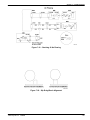
26. Acquire and print a SMPTE test pattern using the lowest available contrast setting (usually contrast
#1). Check the black and white levels on the film. If the levels are set correctly, the 95% and 5%
patches on the film will be equally visible.
If a SMPTE pattern is not available, use a customer image and check the grey scale steps. Again,
using the lowest available contrast setting, inspect the film for visual distinction of the first two and last
two steps of the grey scale. ( Note: A low contrast setting produces low contrast in the middle of the
scale and high contrast at the ends of the scale.) Step 2 should not blend into step 1, and step 15
should not blend into step 16. If the OEM monitor is adjusted properly (refer to Procedure 2-5-9-5), its
grey scale can be used for comparison purposes.
If the VEIB/VIB/EVEIB is set up CORRECTLY: What is normally seen (using a contrast test) is that
the contrast test #1 Dmax (0% square) is lighter than a dark border and Dmin (100% square) is equal
to or slightly darker than a clear border. It is not until later contrast tests that image Dmax and Dmin
equal film Dmax and Dmin. This is acceptable, gives good quality images, and results in the 95% and
5% patches on a SMPTE test film being equally visible. If desired, the image Dmax can be forced to
match the border Dmax; there are two ways to accomplish this:
•
2-32
In the Image Parameters window, set the Match Border parameter to Yes.
1202688
2001 March Rev. L
Section 2 – Installation
•
Increase the Black Level value by one or two digits. This will darken up the image Dmax, and will
also darken up the image Dmin slightly. Do not go past the point of just matching image Dmax to
border Dmax or the 5% patch will start to disappear.
If the VEIB/VIB/EVEIB is set up INCORRECTLY: Using contrast #1, either the 95% or 5% patch will
be gone or faint. If using a customer image, step 2 of the grey scale will blend with or be only faintly
darker than step 1, or step 15 will blend with or be only faintly lighter than step 16. (See Step 27 of
this procedure for possible solutions.)
The other possible incorrect setup of the VEIB/VIB/EVEIB is that image Dmax is significantly lighter
than film Dmax or that image Dmin is significantly darker than film Dmin. Using a contrast test, this can
be seen by the fact that image Dmax and Dmin do not match film Dmax and Dmin until the last few
contrast levels, or they never reach film Dmax and Dmin. (See Step 27 of this procedure for possible
solutions.)
If the VEIB/VIB/EVEIB is set up PERFECTLY: All of the following will be true (with Match Border set
to Yes):
•
Contrast #1 Dmax and Dmin will match the border Dmax and Dmin.
•
Increasing the final Black Level setting by one will make the contrast #1 Dmin slightly darker than
a clear border.
•
Decreasing the final Black Level setting by one will make the contrast #1 Dmax slightly lighter than
a dark border.
This would be the perfect situation; however, in most cases, the VEIB/VIB/EVEIB does not seek black
and white level this accurately.
27. If the black or white level is unacceptable, try any of the following:
•
Assuming that fine tuning has been done, try selecting a different sampling area (use different row
and column settings) when performing the MPC gain adjustment.
•
Try a different image (see Step 1 of this procedure).
•
The Black Level setting can be increased by one or two digits to darken up the image Dmax. This
will also darken up the image Dmin slightly.
•
If still having problems, contact TAC, a PST member, or the local video expert.
28. Make final adjustments to framing parameters to obtain the full frame. The preceding fine tuning steps
may have shifted the horizontal delay so that a pixel is lost on the right or left side of the image. To
check for this, print a film with clear borders (change the Border setting in the Image Parameters
window to 4095). View the image. If a pixel is missing from the left or right side, add or subtract one
pixel from the Horizontal Delay setting. Be sure to change the Border setting back to 0 when fine
tuning is complete.
29. Proceed to Procedure 2-5-9-4.
2-5-9-4.
Set Customer Preferences
When performing the following procedure, note that the method of setting customer preferences varies
depending on the control source.
•
For compact keypad and host control users, density and contrast are set at the local panel of the
IMAGER. Refer to the User Guide for the 8700 IMAGER for details.
•
For compact keypad and host control users, smooth/sharp image processing is set via MPC, based on
interpolation settings. Refer to the MPC for Windows Help file for details.
•
For touch-screen keypad users, density, contrast, and smooth/sharp are all set at the keypad. Refer to
the User Guide for the 8700 LASER IMAGER for details.
2001 March Rev. L
1202688
2-33
Service Manual
1. Have the customer select a typical image that contains the range of contrasts they will be looking for.
2. Acquire the image and print a contrast test.
3. If everything looks too light or too dark, adjust the density setting. If the density setting looks okay,
have the customer select a contrast setting.
4. If the customer finds the image unacceptable at any combination of density and contrast levels, it is
possible that the gain/black level adjustment needs to be redone using a different image, or the OEM
monitor may be misadjusted (refer to Procedure 2-5-9-5).
5. Have the customer select smooth or sharp image processing. If neither smooth nor sharp is
acceptable to the customer, the interpolation settings may need to be changed. Refer to the MPC for
Windows Help file for details on how to change interpolation settings.
2-5-9-5.
OEM Monitor Adjustment
If the customer likes the images, there is no need to adjust the OEM monitor even though it may be
slightly off. However, if the customer is unable to get an acceptable contrast on the images, it may be
necessary to make the following checks and/or adjustments.
Theory
The OEM’s video generator board outputs a video signal to the OEM monitor. This same video signal is
sent to the VEIB/VIB/EVEIB. The window and level controls adjust this video signal, which affects both
the image displayed on the OEM monitor and the image printed on the film. If the monitor’s brightness
and contrast are out of adjustment, the customer will compensate by adjusting the window and level
controls until the image looks good on the monitor. The result of this is that the image on the film and the
image on the monitor do not match. Therefore, it is important that after the brightness and contrast have
been set correctly, the customer does not turn the brightness and contrast knobs. (Over time the monitor
will tend to drift, and the brightness and contrast may have to be adjusted by the OEM.)
Check
With the SMPTE pattern at OEM defined window and level values, the 5% patches (both black and white)
should be visible, and should have equal contrast to the enveloping 100% and 0% boxes around them. If
the 5% patches are not visible, or are not equally visible, the OEM monitor should be adjusted.
•
Ask the OEM to adjust the monitor.
•
Be there when the OEM adjusts the monitor, and ensure that the ambient lighting is the same as the
normal lighting the customer uses when filming.
Adjustment
1. Adjust the white first. Looking at the text, turn the OEM contrast knob until the whites just start to
smear. Then back off the contrast just to the threshold of smearing. The 95%/100% patch in the
SMPTE should now be visible.
2. Adjust the black. Turn the brightness knob until the image starts to fill in. Continue until the black in the
image starts to turn grey. At this point, the 5%/0% patch should be visible. Back off the brightness until
there is an equal balance in the visual ratio of 0% to 5% as 100% to 95%. These two patches are
the key.
2-34
1202688
2001 March Rev. L
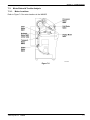
Section 3 – Adjustments
Section 3 – Adjustments
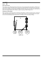
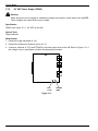
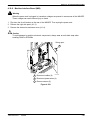
3-1.
Processor Temperature
Specification
There are three temperature zones in the processor. Viewed from the front of the machine, Zone 1 is at
the left end, Zone 2 is in the center, and Zone 3 is at the right end. The temperature measured in all three
zones must be in the range of 122.2° – 122.8° C (252° – 253° F).
Note
This procedure should be performed whenever the processor assembly, processor drum, rotating
processor board (RPB), processor communication board (PCB), or system controller board (SCB) is
replaced, or if drum temperatures are suspected of causing image quality problems.
Special Tools
Temperature meter with probe and block Maintenance Personal Computer (MPC) MPC for Windows
software package.
Note
A probe with a bar type element must be used to perform this procedure. Probes with circular type
elements will not provide accurate readings.
The temperature meter and probe must be calibrated together as a pair at least once per year. If the
probe breaks, a new probe and the meter must be sent in for calibration. Refer to procedure 5-2 for
details.
The temperature meter must be at room temperature when performing this procedure. If the meter
has been brought in from a hot or cold vehicle, allow it to acclimate to room temperature before use.
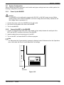
Measurement Setup
1. Raise the top cover of the 8700/8500.
2. Open the processor cover. Verify that the processor rollers are clean and free of deposits.
!
Caution
Deposits on the processor rollers could be knocked loose by the temperature probe, resulting in
damage to the surface of the drum. If necessary, clean the processor before continuing with this
procedure.
3. Close the processor cover.
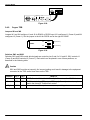
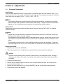
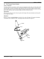
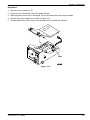
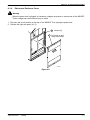
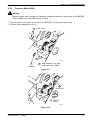
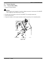
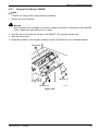
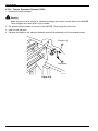
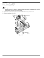
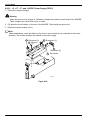
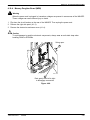
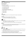
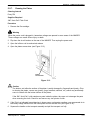
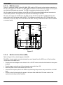
4. Remove the four screws that secure the top cover of the processor clamshell. Do not remove the
cover yet. Refer to Figure 3-1.
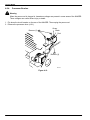
5. Remove the right side panel (4-1-3) from the IMAGER, and pull out the service interlock switch.
6. Close the top cover of the IMAGER.
2001 May Rev. M
1202688
3-1
Service Manual
Remove (4)
Figure 3-1.
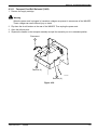
7. Power up the 8700/8500.
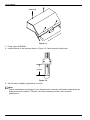
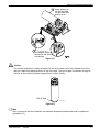
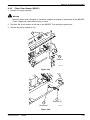
8. Install the block on the probe as shown in Figure 3-2. Clean the probe with alcohol.
2 inches
Figure 3-2.
9. Set the meter to display temperatures in Celsius.
Note
Celsius temperatures are displayed to one decimal point of accuracy. Fahrenheit temperatures are
displayed as whole numbers. Therefore, the Celsius readings provide a more accurate
measurement.
3-2
1202688
2001 May Rev. M
Section 3 – Adjustments
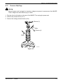
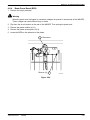
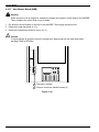
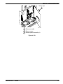
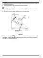
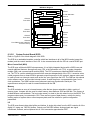
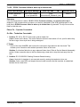
Measurement Procedure
1. When “Ready” is displayed on the the local panel, open the top cover of the IMAGER.
2. Remove the top cover from the processor clamshell.
!
Caution
Hot Surface
The surfaces around the slot in the top of the processor are hot, and hot air exits through the slot.
Do not touch the surfaces around the slot, and do not hold the block above the slot for prolonged
periods of time.
3. Use stainless steel cleaner to wipe clean the slot at the top of the processor and the two exhaust
slots.
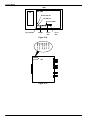
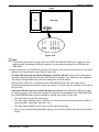
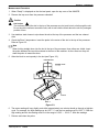
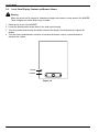
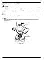
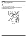
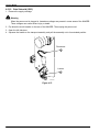
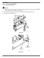
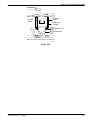
4. Check the Zone 2 temperature. Insert the probe in the center of the slot in the top of the processor.
Refer to Figure 3-3.
Note
When looking straight down into the slot in the top of the processor, three rollers are visible. Insert
the probe between the two rollers closest to the front of the machine. As the rollers turn they will
draw the probe in toward the drum.
5. Allow the block to rest squarely in the slot (see Figure 3-3).
Left Side View
Front
Zone 3
Zone 2
Zone 1
Figure 3-3.
6. The meter reading will vary slightly, and within approximately one minute should go through a high/low
cycle. For example, the high reading may be 122.7° C, and the low reading may be 122.3° C. Both the
high reading and the low reading must be in the range of 122.2° – 122.8° C. Note the readings.
7. Remove and clean the probe.
2001 May Rev. M
1202688
3-3
Service Manual
!
Caution
To prevent damage to the surface of the processor drum, remove and clean the probe after taking
each temperature reading.
8. Check the Zone 1 temperature. Insert the probe at the far left end of the slot, between the two rollers
closest to the front of the machine. Repeat steps 5 through 7.
9. Check the Zone 3 temperature. Insert the probe at the far right end of the slot, between the two rollers
closest to the front of the machine. Repeat steps 5 through 7.
10. If all of the temperatures are within specification, replace and secure the processor clamshell top
cover. If any of the temperatures are out of specification, replace (but do not secure) the processor
clamshell top cover, then perform the following adjustment procedure.
Adjustment Procedure
!
Caution
To prevent damage to the surface of the processor drum, do not leave the probe installed while
performing an adjustment, or while waiting for the processor temperatures to stabilize.
1. Connect the MPC to the MPC port on the rear of the IMAGER.
2. Power up the MPC and start the MPC for Windows program.
3. Do either of the following to select the processor subsystem:
•
Click on the PROC button.
•
Open the Operations menu, and select Subsystem→Processor.
4. Select the Calib button to display the Processor Calibration window.
5. Adjust the temperatures by clicking on the appropriate arrows or by entering positive or negative
values (representing click counts) in the numeric fields below the arrows. For example, if the Zone 1
temperature is too low, click on the Zone 1 up arrow, or enter a positive value in the related numeric
field. If the Zone 3 temperature is too high, click on the Zone 3 down arrow, or enter a negative value
in the related numeric field. Each click produces a change of approximately .06° C.
Note
The adjustment of one zone will affect the temperature of the adjacent zone. Zone 2 will affect Zone
1 and Zone 3 more than Zone 1 or Zone 3 will affect Zone 2. In general, if Zone 2 and either outer
zone are out of specification, adjust Zone 2 first. However, if there is a difference of more than 2.0° C
between Zone 2 and the outer zone(s), adjust the outer zone(s) first, then Zone 2, then the outer
zone(s) again.
6. Wait five minutes for temperatures to stabilize, then repeat the measurement procedure.
Note
For adjustments of more than 2.0° C, the processor may require more than 5 minutes to stabilize
temperatures.
7. Once all zones are within specification, wait five more minutes, then repeat the measurement
procedure to verify the adjustment.
8. Select the Save button to write the new settings into NVRAM.
3-4
1202688
2001 May Rev. M
Section 3 – Adjustments
3-2.
Processor Drum Stripper
Specification
With the processor at operating temperature, there must be a gap of 0.007 + .001 inches between the
processor drum and the stripper, measured at the edges of the film path.
Note
The stripper mechanism expands when heated. To ensure accuracy, the following measurement
must be performed with the processor at operating temperature.
Measurement
1. Raise the top cover of the IMAGER.
2. Open the processor cover.
3. Grasp the handle on the front of the processor/exit assembly and pull the assembly out to its
extended position.
!
Caution
Hot Surface
The surface of the processor drum is hot. Take care when checking the gap.
!
Caution
The feeler gauge can damage the surface of the drum. Take care when checking the gap.
2001 May Rev. M
1202688
3-5
Service Manual
4. Use a .007 inch feeler gauge to check the gap between the drum and the stripper. Check the gap at
the edges of the film path, approximately 1.5 inches in from each end of the stripper blade. Refer to
Figure 3-4. If the gap is set incorrectly, perform the following adjustment procedure.
Top View
.007 + .001 inches
Lock Screw
(M3 Allen)
Adjustment
Screw
Figure 3-4.
Adjustment
1. Remove the lock screws (M3 Allen) at each end of the stripper.
2. Rotate the adjustment screws at each end of the stripper as required to create the gap of .007 + .001
inches. Rotate counterclockwise to decrease the gap, clockwise to increase the gap.
3. There are three locking slots in each adjustment screw. Determine which locking slot is closest to the
hole for the lock screw, then rotate the adjustment screw so this slot lines up with the hole. Install and
tighten the lock screws.
4. Recheck the measurement.
3-6
1202688
2001 May Rev. M
Section 3 – Adjustments
3-3.
Densitometer Calibration
Specification
The A/D Out (Gain) value must be 1640"100, and the A/D Out (Offset) value must be 20"2.
Note
This procedure should be performed whenever a new densitometer is installed. It should also be
performed if the densitometer is suspected of causing AIQC problems; however, be aware that the
densitometer may function perfectly even when not adjusted to specification (i.e., calibrating a
densitometer that is out of specification will not necessarily solve an AIQC problem).
Special Tools
Maintenance Personal Computer (MPC)
MPC for Windows software package
Measurement
1. Connect the MPC to the MPC port on the rear of the IMAGER.
2. Power up the MPC and start the MPC for Windows program.
3. Open the Operations menu and select Diagnostics.
4. Do either of the following to select the processor subsystem:
• Click on the PROC button.
• Open the Operations menu, and select Subsystem→Processor.
5. Select the Densi button to display the Densitometer Test window.
6. Check the values displayed for A/D Out (Gain) and A/D Out (Offset). If either value is out of
specification, perform the adjustment procedure on the following page.
Adjustment
1. Raise the top cover of the IMAGER.
2. Peel back the calibration label that covers the potentiometer access holes on the top side of the
densitometer.
3. Adjust the gain and offset potentiometers as required to bring both readings within specification.
8700–108C
Figure 3-5.
2001 May Rev. M
1202688
3-7
Service Manual
3-4.
Density Patch Offset
Specification
The top edge of the density patch must be located 7.0 " 1.0 mm from the top edge of the film.
Special Tools
Small flat-blade insulated screwdriver
Measurement
1. Power up the imager and wait for it to warm up to operating temperature.
2. Initiate a density test from the local panel.
3. Measure the distance from the top edge of the test print to the top edge of the density patch. If it is not
within specification, perform the following adjustment procedure.
Adjustment
1. Remove the supply cartridge.
!
Warning
When the power cord is plugged in, hazardous voltages are present in some areas of the IMAGER.
These voltages can cause severe injury or death.
2. Flip down the circuit breaker on the rear of the IMAGER, then unplug the power cord.
3. Remove the front panel (4-1-1).
4. Locate the offset potentiometer access hole on the front of the optics module. (The offset and gain
pots are mounted on the Y-galvo driver board, approximately 1.5 inches behind the front cover of the
optics module.)
Optics Module
CN702
Gain
Offset
CN703
CN701
CN704
Figure 3-6.
!
Caution
To avoid damage to the Y-galvo driver board, wear an anti-static wrist strap when adjusting the
offset potentiometer. Take care not to touch any other components on the Y-galvo driver board.
5. Use an insulated screwdriver to adjust the offset pot. A 1/4 turn of the pot moves the density patch
approximately 0.5 mm. Turn the pot clockwise to increase the distance between the top of the film and
the top of the density patch; turn the pot counterclockwise to decrease the distance.
Note
Do not adjust the gain pot. The gain pot affects the image size in the Y-direction.
6. Install the front panel and the supply cartridge.
7. Power up the imager and repeat the measurement procedure.
3-8
1202688
2001 May Rev. M
Section 3 – Adjustments
3-5.
Exit Transport Sensor Actuator
Theory of Operation
The sensor actuator is mounted on a shaft. A spring is wrapped around the other end of the shaft. As film
exits the imager, it pushes on the spring, which rotates the shaft and actuator slightly counterclockwise,
unblocking the sensor. Once the film has cleared the spring, the spring drops back into the slot in the exit
guide, which rotates the shaft and actuator slightly clockwise, blocking the sensor.
Specification
With the spring resting in the slot in the exit guide, the left edge of the sensor actuator must line up with
the left edge of the sensor.
Adjustment
Rotate the actuator counterclockwise as required to line up the left edges of the sensor and actuator.
The actuator can be rotated a full 360°; the spring will slip on the shaft. See Figure 3-7.
Actuator
Sensor
Slot
Spring
Figure 3-7.
2001 May Rev. M
1202688
3-9
Service Manual
3-6.
!
Local Panel Display Contrast and Buzzer Volume
Warning
When the power cord is plugged in, hazardous voltages are present in some areas of the IMAGER.
These voltages can cause severe injury or death.
1. Raise the top cover of the IMAGER.
2. Locate the potentiometer access holes in the local panel housing.
3. Turn the contrast potentiometer clockwise to darken the display, counterclockwise to lighten the
display.
4. Turn the volume potentiometer clockwise to increase the buzzer volume, counterclockwise to
decrease the volume.
Volume
Contrast
Figure 3-8.
3-10
1202688
2001 May Rev. M
Section 3 – Adjustments
3-7.
3-7-1.
!
Power Supply Voltages
+5, +17, –17, and +24 VDC Power Supply (PS901)
Warning
When the power cord is plugged in, hazardous voltages are present in some areas of the IMAGER.
These voltages can cause severe injury or death.
Specification
PS901 must output the following DC voltages:
+5.1 " 0.1 VDC
+17.3 " 0.3 VDC
–17.3 " 0.3 VDC
+24.3 " 0.5 VDC
Special Tools
Digital Voltmeter
Measurement
1. Remove the right side panel (4-1-3).
2. Remove the electronics enclosure cover (4-1-4).
3. To gain access to the Machine Interface Board (MIB), swing out the panel that holds the memory
boards.
4. Check the voltages by connecting a voltmeter to the appropriate test points on the MIB. The table
below lists the test points; Figure 3-9 on the following page shows the test point locations. If any of the
voltages are out of specification, perform the adjustment procedure.
MIB Test Points
2001 May Rev. M
1202688
TP5H1 (+5V)
TP7G1 (LOGIC GND)
TP5I8 (+17V)
TP6I1 (–17V)
TP5I9 (AGND)
TP7K1 (+24V)
TP6K1 (GND)
3-11
Service Manual
MIB
3M ASSY 78–8094–5102–0
TP5H1
(+5V)
TP5I8
(+17V)
TP5I9
(AGND)
TP6I1
(–17V)
TP6K1
(GND)
TP7K1
(+24V)
TP7G1
(LOGIC GND)
Figure 3-9.
3-12
1202688
2001 May Rev. M
Section 3 – Adjustments
Adjustment
1. Remove the rear panel (4-1-2).
2. Loosen the two screws that secure the power module.
3. Slide the power module out of the imager. Do not disconnect the power module cables.
4. Remove the plastic plugs covering the adjustment potentiometers.
5. Rotate the appropriate output adjustment potentiometer(s) as required. Refer to Figure 3-10.
OUTPUT
ADJ.
+5V
O
1
OUTPUT
ADJ.
–17V +17V +24V
O
O
O
4
3
2
Figure 3-10.
2001 May Rev. M
1202688
3-13
Service Manual
3-7-2.
!
-5.2 VDC Power Supply (PS902)
Warning
When the power cord is plugged in, hazardous voltages are present in some areas of the IMAGER.
These voltages can cause severe injury or death.
Specification
PS902 must output -5.2 " 0.2 VDC for the VIB.
Special Tools
Digital Voltmeter
Measurement
1. Remove the right side panel (4-1-3).
2. Remove the electronics enclosure cover (4-1-4).
3. Connect a voltmeter to TP31 and TPGND2 in the lower right corner of the VIB. Refer to Figure 3-11. If
the voltage is out of specification, perform the adjustment procedure.
VIB
TP31
(–5.2V)
TPGND2
(GND)
Figure 3-11.
3-14
1202688
2001 May Rev. M
Section 3 – Adjustments
Adjustment
1. Remove the rear panel (4-1-2).
2. Loosen the two screws that secure the power module.
3. Slide the power module out of the imager. Do not disconnect the power module cables.
4. Remove the power module cover. Refer to Figure 3-12.
5. Rotate potentiometer VR51 (next to the terminal block on PS902) as required.
PS902
Figure 3-12.
2001 May Rev. M
1202688
3-15
Service Manual
3-8.
Multifeed Board (MFB) Actuator
Note
This procedure should be performed only if the MFB or associated hardware has been replaced.
Special Tools
Maintenance Personal Computer (MPC)
MPC for Windows software package
Measurement
1. Connect the MPC to the MPC port on the rear of the IMAGER.
2. Power up the MPC and start the MPC for Windows program.
3. Open the Operations menu and select Diagnostics.
4. Click on the SCB button, or open the Operations menu and select Subsystem→SCB.
5. Select the Cmd button to display the Command window.
6. Type show adc=9 in the Command field, then press Enter or click OK.
7. Calculate the average of the comma-separated numbers displayed in the Response field.
Note
The response actually includes 30 numbers; however, the average of the first 8 numbers is sufficient
for this purpose. (The numbers should be in the range of 1000 to 3000.)
8. Type show adc=10 in the Command field, then press Enter or click OK.
9. Calculate the average of the comma-separated numbers displayed in the Response field.
10. If the difference between the average values calculated in steps 8 and 9 is greater than 200, perform
the following adjustment procedure. If the difference is less than 200, perform the pickup arm height
calibration (3-10).
3-16
1202688
2001 May Rev. M
Section 3 – Adjustments
Adjustment
!
Warning
When the power cord is plugged in, hazardous voltages are present in some areas of the IMAGER.
These voltages can cause severe injury or death.
Note
When performing the following procedure, move the actuator in small increments. The adjustment is
very sensitive.
1. Remove the supply cartridge.
2. Open the left side door.
3. Squeeze the handle on the transport assembly and pull the assembly out to its extended position.
4. Use a long Phillips head screwdriver to loosen the screw that secures the actuator for the sensor on
the MFB (Figure 3-13).
5. Move the actuator slightly and retighten the screw. (Move the actuator up if Channel 10 is higher.
Move it down if Channel 9 is higher.)
6. Repeat the measurement and adjustment procedures as required.
7. Slide the transport back into place, close the left side door, and install the supply cartridge.
8. Perform the pickup arm height calibration (3-10).
Actuator
MFB
Figure 3-13.
2001 May Rev. M
1202688
3-17
Service Manual
3-9.
Multifeed Board (MFB) Actuator (Alternative Adjustment)
Do this procedure only if the MFB or associated hardware has been replaced.
Specification
ADC values within 200 of each other and within a range of 1530 to1850
Special Tools
•
Maintenance Personal Computer (MPC)
•
MPC for Windows software package
•
Dual-Trace Scope or Dual-Channel Digital Multimeter
Measurement
1. Connect the MPC to the MPC port on the rear of the IMAGER.
2. Power up the MPC and start the MPC for Windows program.
3. Open the Operations menu and select Diagnostics.
4. Click on the SCB button, or open the Operations menu and select Subsystem→SCB.
5. Select the Cmd button to display the Command window.
6. Type show adc=9 in the Command field, then press Enter or click OK. Record the number.
7. Type show adc=10 in the Command field, then press Enter or click OK. Record the number.
8. For both steps 6 and 7, calculate the average of the comma-separated numbers displayed in the
Response field. The two averages must be within 200 of each other, and within the range of 1530 to
1850.
Note
The response actually includes 30 numbers. However, the average of the first 8 numbers is sufficient
for this purpose.
9. If the average values or range are not within spec, perform the following adjustment procedure. If they
are within spec, perform the pickup arm height calibration (3-10).
Adjustment
!
Warning
When the power cord is plugged in, hazardous voltages are present in some areas of the imager.
These voltages can cause severe injury or death.
1. Remove the supply cartridge and open the left side door.
2. Squeeze the handle on the transport assembly and extend the assembly fully.
3. Hook up a two-channel scope to TP1 and TP2 on the Multifeed Board (Figure 3-14). (You can use a
dual–channel multimeter, if you wish.) Connect at least one ground lead to TP3.
3-18
1202688
2001 May Rev. M
Section 3 – Adjustments
TP1
TP2
Ground
Figure 3-14.
4. Use a long Phillips head screwdriver to loosen the screw that secures the actuator for the sensor on
the MFB (Figure 3-15).
MFB
Actuator
Figure 3-15.
5. Move the actuator slightly forward or backward until the scope traces overlay each other (at about 5
vdc). (Use the 2-Volt per Division scale.)
Note
On a multimeter the readings should be within 0.25 volts of each other.
6. Retighten the actuator screw.
7. Repeat the Measurement and Adjustment procedures as needed to achieve the difference spec
(200).
8. If you cannot achieve the range value, adjust R6 (see Figure 3-16) to between 1530 and 1850.
R6
Figure 3-16.
9. Slide the transport back into place, close the left side door, and install the supply cartridge.
10. Do the pickup arm height calibration (3-10).
2001 May Rev. M
1202688
3-19
Service Manual
3-10. Pickup Arm Height Calibration
Note
This procedure should be performed after the multifeed board (MFB) actuator adjustment (8 or 3-9)
has been performed, or after the system control board (SCB) has been replaced.
Special Tools
Maintenance Personal Computer (MPC)
MPC for Windows software package
Adjustment
1. Connect the MPC to the MPC port on the rear of the IMAGER.
2. Power up the MPC and start the MPC for Windows program.
3. Click on the SCB button, or open the Operations menu and select Subsystem→SCB.
4. Select the Config button to display the 8700/8500 Imager Setup window.
5. Select the Pickup Arm Height button.
6. A confirmation window is displayed. Select the Yes button to initiate the calibration.
Note
For a detailed description of the events that occur during the calibration process, refer to the MPC for
Windows Help file.
3-20
1202688
2001 May Rev. M
Section 3 – Adjustments
3-11. Processor Drum Brushes
This procedure must be performed every PM and when indicated by troubleshooting.
Specification
Brush surfaces must completely contact slip ring surfaces. Minimum height of ground brush must be 3.1
mm. Minimum height of other brushes must be 2.3 mm.
Measurement
1. Remove power and unplug the power cord.
!
Warning
When the power cord is plugged in, hazardous voltages are present in some areas of the IMAGER.
These voltages can cause severe injury or death.
2. Raise the top cover of the IMAGER. Grasp the handle of the processor/exit assembly and pull the
assembly out to its extended position
3. Check the side-to-side and front-to-back alignment of the brushes with respect to the slip rings. The
alignment must be as shown in Figure 3-17 and there must be no sign of arcing (burns). (Arcing will
interrupt power to the RPB.) If necessary, adjust as instructed below.
4. Remove the processor drum (see procedure 4-2-1) and check the height of the brushes. If they are
below the minimum heights shown in Figure 3-17, replace the brush assembly (see procedure 4-2-4).
Adjustment
Note
The brush assembly is mounted with two screws, and is longer on one side. If installed incorrectly,
the brushes will touch the slip ring on only one corner.
1. Loosen two screws and adjust the brush assembly side-to-side so the brush surfaces completely
contact the slip ring surfaces. Then tighten the two screws.
2. Slide the drum assembly side-to-side and verify that the slip rings and brushes remain in full contact.
Readjust as necessary.
1
3.1 mm min. 2.3 mm min.
Brushes
Centered
Front to Back
Alignment
Slip
Rings
Brush
Assembly
Brushes
Centered
Side to Side
Alignment
8700-97C
Figure 3-17. Brush to Slip Ring Alignment
2001 May Rev. M
1202688
3-21
Service Manual
BLANK PAGE
3-22
1202688
2001 May Rev. M
Section 4 – Disassembly/Reassembly
Section 4 – Disassembly/Reassembly
4-1.
4-1-1.
Covers and Panels
Front Panel
1. Remove the supply cartridge.
!
Warning
When the power cord is plugged in, hazardous voltages are present in some areas of the IMAGER.
These voltages can cause severe injury or death.
2. Flip down the circuit breaker on the rear of the IMAGER. Then unplug the power cord.
3
4
Remove
bracket
(3 screws)
Lift front panel
up and away
from frame
8700-68C
Figure 4-1.
2001 March Rev. L
1202688
4-1
Service Manual
4-1-2.
Rear Panel
1. Remove the supply cartridge.
!
Warning
When the power cord is plugged in, hazardous voltages are present in some areas of the IMAGER.
These voltages can cause severe injury or death.
2. Flip down the circuit breaker on the rear of the IMAGER. Then unplug the power cord.
3. Raise the top cover of the IMAGER.
4. Grasp the handle on the front of the processor/exit assembly and pull the assembly out to its
extended position. Locate the connector on the inside rear wall of the imager (behind the processor).
5. Unlatch and open the filter housing. Remove the filter to reduce the weight of the housing.
6
Loosen 2
screws and
disconnect
8700-72C
Figure 4-2.
4-2
1202688
2001 March Rev. L
Section 4 – Disassembly/Reassembly
8
Remove (2)
9
Lift
housing up
and away
from rear
panel
7
Loosen (2)
8700-71C
Figure 4-3.
10 Remove (2)
12 Tilt rear panel
out and lift up
11 Remove (2)
8700-70C
Figure 4-4.
2001 March Rev. L
1202688
4-3
Service Manual
4-1-3.
!
Right Side Panel
Warning
When the power cord is plugged in, hazardous voltages are present in some areas of the IMAGER.
These voltages can cause severe injury or death.
1. Flip down the circuit breaker on the rear of the IMAGER. Then unplug the power cord.
2. Raise the top cover of the IMAGER.
3
Loosen (2)
4
Pull top of side panel
away from frame
and lift up
8700-76C
Figure 4-5.
4-4
1202688
2001 March Rev. L
Section 4 – Disassembly/Reassembly
4-1-4.
!
Electronics Enclosure Cover
Warning
When the power cord is plugged in, hazardous voltages are present in some areas of the IMAGER.
These voltages can cause severe injury or death.
1. Flip down the circuit breaker on the rear of the IMAGER. Then unplug the power cord.
2. Remove the right side panel (4-1-3).
3
4
Loosen (8)
Lift cover up and
away from frame
8700-29C
Figure 4-6.
2001 March Rev. L
1202688
4-5
Service Manual
4-2.
4-2-1.
!
Processor/Exit Assembly
Processor Drum
Warning
When the power cord is plugged in, hazardous voltages are present in some areas of the IMAGER.
These voltages can cause severe injury or death.
1. Flip down the circuit breaker on the rear of the IMAGER. Then unplug the power cord.
2. Raise the top cover of the IMAGER.
3. Grasp the handle on the front of the processor/exit assembly and pull the assembly out to its
extended position.
4
Remove e-ring and disengage support arm
Open
6
5
Remove
8700-86C
Figure 4-7.
!
Caution
Hot Surface
When the IMAGER is initially powered down, the processor drum and rollers are hot. Take care
when removing the drum.
!
4-6
Caution
The surface of the drum is easily damaged by fingernails and jewelry. Handle the drum with one
hand on the large gear and the other hand on the opposite endcap. Do not touch the gray silicone
surface of the drum.
1202688
2001 March Rev. L
Section 4 – Disassembly/Reassembly
8
Grasp bearing on
left end and gear
on right end, then
remove drum
7
Pull stripper away
from drum and secure
with latches
Figure 4-8.
!
Caution
The surface of the drum is easily damaged. Do not lay the drum on its side. Instead, lay a roll of
tape on a table, then stand the drum on top of the tape. The type of tape is irrelevant, as long as
the core of the roll has a diameter greater than 2 inches (51mm).
Roll of Tape
8700-107C
Figure 4-9.
Note
After a new drum has been installed, the processor temperature adjustment must be performed
(procedure 3-1).
2001 March Rev. L
1202688
4-7
Service Manual
4-2-2.
Processor Rollers
1. Remove power and remove the processor drum (4-2-1).
Note
There are three sets of rollers in the processor. The top and middle sets are in the upper half of the
housing, and the bottom set is in the lower half of the housing. The middle and bottom sets each
have ten rollers. The top set has only nine rollers. When replacing rollers in the top set, do not install
a roller in the topmost location (closest to the handle on the processor cover).
The springs on the roller retainers are position-specific and must not be removed. If a spring is
damaged, replace the retainer assembly.
Note
The arrows on the retainers should all point in the direction of Film Flow.
2 Remove (3 screws per clip)
3 Remove
rollers
Figure 4-10.
4-8
1202688
2001 March Rev. L
Section 4 – Disassembly/Reassembly
4-2-3.
!
Processor Motor (M301)
Warning
When the power cord is plugged in, hazardous voltages are present in some areas of the IMAGER.
These voltages can cause severe injury or death.
1. Flip down the circuit breaker on the rear of the IMAGER. Then unplug the power cord.
2. Remove the processor drum (4-2-1).
3
Close cover
8700-95C
4
Remove
5
Slide assembly in to align
motor with hole in frame
Figure 4-11.
6
Disconnect
7
Remove
motor
8700-96C
Figure 4-12.
2001 March Rev. L
1202688
4-9
Service Manual
4-2-4.
!
Processor Brushes
Warning
When the power cord is plugged in, hazardous voltages are present in some areas of the IMAGER.
These voltages can cause severe injury or death.
1. Flip down the circuit breaker on the rear of the IMAGER. Then unplug the power cord.
2. Remove the processor drum (4-2-1).
Remove (2) 4
Green
Black
Red
3
Remove (3)
8700-97C
Figure 4-13.
4-10
1202688
2001 March Rev. L
Section 4 – Disassembly/Reassembly
4-2-5.
!
Processor Communication Board (PCB)
Warning
When the power cord is plugged in, hazardous voltages are present in some areas of the IMAGER.
These voltages can cause severe injury or death.
1. Flip down the circuit breaker on the rear of the IMAGER. Then unplug the power cord.
2. Raise the top cover of the IMAGER.
3. Grasp the handle on the front of the processor/exit assembly and pull the assembly out to its
extended position.
Open
5
4
Remove
8700-160C
Figure 4-14.
6
Remove (4)
5
Disconnect
8700-98C
Figure 4-15.
Note
After a new PCB has been installed, the processor temperature adjustment must be performed
(procedure 3-1).
2001 March Rev. L
1202688
4-11
Service Manual
4-2-6.
!
Rotating Processor Board (RPB)
Warning
When the power cord is plugged in, hazardous voltages are present in some areas of the IMAGER.
These voltages can cause severe injury or death.
1. Flip down the circuit breaker on the rear of the IMAGER. Then unplug the power cord.
2. Remove the processor drum (4-2-1).
Note
When reassembling, be aware of the colors of the four wires with spade connectors. The color code
is printed next to the terminals on the RPB.
Note
After a new RPB has been installed, the processor temperature adjustment must be performed
(procedure 3-1).
5
Remove (3)
4
Disconnect (2)
3
Disconnect(4)
8700-99C
Figure 4-16.
4-12
1202688
2001 March Rev. L
Section 4 – Disassembly/Reassembly
4-2-7.
!
Processor Slip Rings
Warning
When the power cord is plugged in, hazardous voltages are present in some areas of the IMAGER.
These voltages can cause severe injury or death.
1. Flip down the circuit breaker on the rear of the IMAGER. Then unplug the power cord.
2. Remove the processor drum (4-2-1).
3. Remove the rotating processor board (4-2-6).
5
Remove (3)
White
4 Remove (2)
Black
8700-100C
Figure 4-17.
2001 March Rev. L
1202688
4-13
Service Manual
4-2-8.
!
Processor Thermal Fuses
Warning
When the power cord is plugged in, hazardous voltages are present in some areas of the IMAGER.
These voltages can cause severe injury or death.
1. Flip down the circuit breaker on the rear of the IMAGER. Then unplug the power cord.
2. Remove the processor drum (4-2-1).
!
Caution
The drum must be laid on its side in order to remove the thermal fuses. To prevent damage to the
surface of the drum, lay the drum on a soft, lint-free object (for example, a folded cloth towel
covered with the lint-free cloths used for cleaning the drum).
4
Remove
8700-101C
3 Remove (4)
(M2 Allen)
Figure 4-18.
4-14
1202688
2001 March Rev. L
Section 4 – Disassembly/Reassembly
4-2-9.
!
Exit Assembly
Warning
When the power cord is plugged in, hazardous voltages are present in some areas of the IMAGER.
These voltages can cause severe injury or death.
1. Flip down the circuit breaker on the rear of the IMAGER. Then unplug the power cord.
2. Raise the top cover of the IMAGER.
3. Grasp the handle on the front of the processor/exit assembly and pull the assembly out to its
extended position.
Slide locking tab to
right, then disconnect
4
Remove (4)
6
5
Disconnect (3)
8700-91C
Figure 4-19.
2001 March Rev. L
1202688
4-15
Service Manual
4-2-10. Exit Motor (M303)
!
Warning
When the power cord is plugged in, hazardous voltages are present in some areas of the IMAGER.
These voltages can cause severe injury or death.
1. Flip down the circuit breaker on the rear of the IMAGER. Then unplug the power cord.
2. Raise the top cover of the IMAGER.
3. Grasp the handle on the front of the processor/exit assembly and pull the assembly out to its
extended position.
4
Disconnect
8700-94C
5
Remove (4)
Figure 4-20.
4-16
1202688
2001 March Rev. L
Section 4 – Disassembly/Reassembly
4-2-11. Processor Exit Sensor (SW301)
!
Warning
When the power cord is plugged in, hazardous voltages are present in some areas of the IMAGER.
These voltages can cause severe injury or death.
1. Flip down the circuit breaker on the rear of the IMAGER. Then unplug the power cord.
2. Remove the exit assembly (4-2-9).
Remove
4
3
Remove
8700-110C
Figure 4-21.
5
Remove
Disconnect
7
6
Press actuator and
slide out sensor
8700-116C
Figure 4-22.
2001 March Rev. L
1202688
4-17
Service Manual
4-2-12. Processor Entrance Sensor (SW302)
!
Warning
When the power cord is plugged in, hazardous voltages are present in some areas of the IMAGER.
These voltages can cause severe injury or death.
1. Flip down the circuit breaker on the rear of the IMAGER. Then unplug the power cord.
2. Remove the processor drum (4-2-1).
3. Remove the exit assembly (4-2-9).
Remove (4)
5
4
Remove (4)
6
Disconnect
8700-111C
Figure 4-23.
4-18
1202688
2001 March Rev. L
Section 4 – Disassembly/Reassembly
4-2-13. Exit Transport Sensor (SW304)
!
Warning
When the power cord is plugged in, hazardous voltages are present in some areas of the IMAGER.
These voltages can cause severe injury or death.
1. Flip down the circuit breaker on the rear of the IMAGER. Then unplug the power cord.
2. Raise the top cover of the IMAGER.
Note
After reassemby, check the adjustment of the sensor actuator (procedure 3-5).
3
4
Remove
(2)
Remove (2)
8700-92C
5
Disconnect
Figure 4-24.
2001 March Rev. L
1202688
4-19
Service Manual
4-2-14. Densitometer Assembly
!
Warning
When the power cord is plugged in, hazardous voltages are present in some areas of the IMAGER.
These voltages can cause severe injury or death.
1. Flip down the circuit breaker on the rear of the IMAGER. Then unplug the power cord.
2. Remove the exit assembly (4-2-9).
Note
After a new densitometer has been installed, a densitometer calibration must be performed
(procedure 3-3).
8700-93C
3
Remove (4)
Figure 4-25.
4-20
1202688
2001 March Rev. L
Section 4 – Disassembly/Reassembly
4-3.
4-3-1.
Transport Assembly
Transport Motor (M402)
1. Remove the supply cartridge.
!
Warning
When the power cord is plugged in, hazardous voltages are present in some areas of the IMAGER.
These voltages can cause severe injury or death.
2. Flip down the circuit breaker on the rear of the IMAGER. Then unplug the power cord.
3. Open the left side door.
4. Squeeze the handle on the transport assembly and pull the assembly out to its extended position.
7
Remove
6
Disconnect
5
Remove (2)
8700-06C
Figure 4-26.
2001 March Rev. L
1202688
4-21
Service Manual
4-3-2.
Transport Feed Roll Motor (M401)
1. Remove the supply cartridge.
!
Warning
When the power cord is plugged in, hazardous voltages are present in some areas of the IMAGER.
These voltages can cause severe injury or death.
2. Flip down the circuit breaker on the rear of the IMAGER. Then unplug the power cord.
3. Remove the rear panel from the IMAGER (4-1-2).
4. Open the left side door.
5. Squeeze the handle on the transport assembly and pull the assembly out to its extended position.
8
Remove (2)
7
Disconnect
6
Remove (2)
8700-164C
Figure 4-27.
4-22
1202688
2001 March Rev. L
Section 4 – Disassembly/Reassembly
4-3-3.
Platen Motor (M403)
1. Remove the supply cartridge.
!
Warning
When the power cord is plugged in, hazardous voltages are present in some areas of the IMAGER.
These voltages can cause severe injury or death.
2. Flip down the circuit breaker on the rear of the IMAGER. Then unplug the power cord.
3. Remove the rear panel from the IMAGER (4-1-2).
4. Open the left side door.
5. Squeeze the handle on the transport assembly and pull the assembly out to its extended position.
8
Remove (2)
6
Remove (2)
7
Disconnect
8700-163C
Figure 4-28.
2001 March Rev. L
1202688
4-23
Service Manual
4-3-4.
Platen Entrance Sensor (SW402)
1. Remove the supply cartridge.
!
Warning
When the power cord is plugged in, hazardous voltages are present in some areas of the IMAGER.
These voltages can cause severe injury or death.
2. Flip down the circuit breaker on the rear of the IMAGER. Then unplug the power cord.
3. Open the left side door.
4. Squeeze the handle on the transport assembly and pull the assembly out to its extended position.
Disconnect
5
6
Remove
8700-18C
Figure 4-29.
4-24
1202688
2001 March Rev. L
Section 4 – Disassembly/Reassembly
4-3-5.
Platen Exit Sensor (SW403)
1. Remove the supply cartridge.
!
Warning
When the power cord is plugged in, hazardous voltages are present in some areas of the IMAGER.
These voltages can cause severe injury or death.
2. Flip down the circuit breaker on the rear of the IMAGER. Then unplug the power cord.
3. Open the left side door.
4. Squeeze the handle on the transport assembly and pull the assembly out to its extended position.
Disconnect
5
6
Remove
8700-166C
Figure 4-30.
2001 March Rev. L
1202688
4-25
Service Manual
4-3-6.
Transport Midpoint Sensor (SW404)
1. Remove the supply cartridge.
!
Warning
When the power cord is plugged in, hazardous voltages are present in some areas of the IMAGER.
These voltages can cause severe injury or death.
2. Flip down the circuit breaker on the rear of the IMAGER. Then unplug the power cord.
3. Open the left side door.
4. Squeeze the handle on the transport assembly and pull the assembly out to its extended position.
Disconnect
5
6
Remove
8700-17C
Figure 4-31.
4-26
1202688
2001 March Rev. L
Section 4 – Disassembly/Reassembly
4-3-7.
Transport Feed Sensor (SW405)
Note
SW405 is no longer used in later production machines.
1. Remove the supply cartridge.
!
Warning
When the power cord is plugged in, hazardous voltages are present in some areas of the IMAGER.
These voltages can cause severe injury or death.
2. Flip down the circuit breaker on the rear of the IMAGER. Then unplug the power cord.
3. Open the left side door.
4. Squeeze the handle on the transport assembly and pull the assembly out to its extended position.
Disconnect
5
6
Remove (2)
7
Remove (2)
8700-140C
Figure 4-32.
2001 March Rev. L
1202688
4-27
Service Manual
4-3-8.
Tongue Depressor Sensor (SW406)
1. Remove the supply cartridge.
!
Warning
When the power cord is plugged in, hazardous voltages are present in some areas of the IMAGER.
These voltages can cause severe injury or death.
2. Flip down the circuit breaker on the rear of the IMAGER. Then unplug the power cord.
3. Open the left side door.
4. Squeeze the handle on the transport assembly and pull the assembly out to its extended position.
Disconnect
8
5
Remove
Remove (2)
7
6
Remove
8700-143C
Figure 4-33.
4-28
1202688
2001 March Rev. L
Section 4 – Disassembly/Reassembly
4-3-9.
Tongue Depressor Interrupt Switch (SW407)
1. Remove the supply cartridge.
!
Warning
When the power cord is plugged in, hazardous voltages are present in some areas of the IMAGER.
These voltages can cause severe injury or death.
2. Flip down the circuit breaker on the rear of the IMAGER. Then unplug the power cord.
3. Open the left side door.
4. Squeeze the handle on the transport assembly and pull the assembly out to its extended position.
Remove (2)
7
6
Remove (2)
5
Disconnect
8700-144C
Figure 4-34.
2001 March Rev. L
1202688
4-29
Service Manual
4-3-10. Tongue Depressor Solenoid (Y401)
1. Remove the supply cartridge.
!
Warning
When the power cord is plugged in, hazardous voltages are present in some areas of the IMAGER.
These voltages can cause severe injury or death.
2. Flip down the circuit breaker on the rear of the IMAGER. Then unplug the power cord.
3. Open the left side door.
4. Squeeze the handle on the transport assembly and pull the assembly out to its extended position.
Remove (4)
6
5
Disconnect
8700-145C
Figure 4-35.
4-30
1202688
2001 March Rev. L
Section 4 – Disassembly/Reassembly
4-3-11. Transport Feed Roll Solenoid (Y402)
1. Remove the supply cartridge.
!
Warning
When the power cord is plugged in, hazardous voltages are present in some areas of the IMAGER.
These voltages can cause severe injury or death.
2. Flip down the circuit breaker on the rear of the IMAGER. Then unplug the power cord.
3. Open the left side door.
4. Squeeze the handle on the transport assembly and pull the assembly out to its extended position.
Disconnect
5
7
Remove (4)
6
Remove (4)
8700-05C
Figure 4-36.
2001 March Rev. L
1202688
4-31
Service Manual
4-3-12. Gate Solenoid (Y403)
1. Remove the supply cartridge.
!
Warning
When the power cord is plugged in, hazardous voltages are present in some areas of the IMAGER.
These voltages can cause severe injury or death.
2. Flip down the circuit breaker on the rear of the IMAGER. Then unplug the power cord.
3. Open the left side door.
4. Squeeze the handle on the transport assembly and pull the assembly out to its extended position.
Disconnect
5
Loosen
6
8700-07C
Figure 4-37.
4-32
1202688
2001 March Rev. L
Section 4 – Disassembly/Reassembly
4-3-13. Multifeed Board (MFB)
1. Remove the supply cartridge.
!
Warning
When the power cord is plugged in, hazardous voltages are present in some areas of the IMAGER.
These voltages can cause severe injury or death.
2. Flip down the circuit breaker on the rear of the IMAGER. Then unplug the power cord.
3. Open the left side door.
4. Squeeze the handle on the transport assembly and pull the assembly out to its extended position.
6
Remove (2)
Remove (2)
5
7
Disconnect
8700-141C
Figure 4-38.
2001 March Rev. L
1202688
4-33
Service Manual
4-4.
4-4-1.
Pickup Assembly
Pickup Module
1. Remove the supply cartridge.
!
Warning
When the power cord is plugged in, hazardous voltages are present in some areas of the IMAGER.
These voltages can cause severe injury or death.
2. Flip down the circuit breaker on the rear of the IMAGER. Then unplug the power cord.
3. Remove the front panel (4-1-1).
8700-123C
4
Remove (2)
Figure 4-39.
4-34
1202688
2001 March Rev. L
Section 4 – Disassembly/Reassembly
Disconnect (2)
7
6
Disconnect
5
Remove (4)
8700-120C
Figure 4-40.
9
Loosen (4)
(M4 Allen)
8
Disconnect (2)
10
Support module
from below, and
slide toward
front of imager
8700-74C
Figure 4-41.
2001 March Rev. L
1202688
4-35
Service Manual
4-4-2.
Vacuum Relay (K501)
1. Remove the supply cartridge.
!
Warning
When the power cord is plugged in, hazardous voltages are present in some areas of the IMAGER.
These voltages can cause severe injury or death.
2. Flip down the circuit breaker on the rear of the IMAGER. Then unplug the power cord.
3. Remove the front panel (4-1-1).
Note
When reassembling, check the labels on the wires to ensure that they are connected to the correct
terminals. The terminal numbers are marked on the relay.
4
Loosen (2)
6
Disconnect
(4)
7
Remove (2)
5
Remove
8700-130C
Figure 4-42.
4-36
1202688
2001 March Rev. L
Section 4 – Disassembly/Reassembly
4-4-3.
Pickup Motor (M501)
1. Remove the supply cartridge.
!
Warning
When the power cord is plugged in, hazardous voltages are present in some areas of the IMAGER.
These voltages can cause severe injury or death.
2. Flip down the circuit breaker on the rear of the IMAGER. Then unplug the power cord.
3. Remove the pickup module (4-4-1).
5
Disconnect
4
Remove
(4)
6
Remove (2)
8700-127C
Figure 4-43.
2001 March Rev. L
1202688
4-37
Service Manual
4-4-4.
Vacuum Pump (M502)
1. Remove the supply cartridge.
!
Warning
When the power cord is plugged in, hazardous voltages are present in some areas of the IMAGER.
These voltages can cause severe injury or death.
2. Flip down the circuit breaker on the rear of the IMAGER. Then unplug the power cord.
3. Remove the pickup module (4-4-1).
Remove (4)
6
4
5
Disconnect
Disconnect
8700-126C
Figure 4-44.
4-38
1202688
2001 March Rev. L
Section 4 – Disassembly/Reassembly
4-4-5.
Picker Down Sensor (SW501)
1. Remove the supply cartridge.
!
Warning
When the power cord is plugged in, hazardous voltages are present in some areas of the IMAGER.
These voltages can cause severe injury or death.
2. Flip down the circuit breaker on the rear of the IMAGER. Then unplug the power cord.
3. Remove the pickup module (4-4-1).
4 Remove (2)
5
Remove
8700-125C
Figure 4-45.
6
7
Disconnect
Remove (2)
8700-142C
Figure 4-46.
2001 March Rev. L
1202688
4-39
Service Manual
4-4-6.
Film Out Sensor (SW502)
1. Remove the supply cartridge.
!
Warning
When the power cord is plugged in, hazardous voltages are present in some areas of the IMAGER.
These voltages can cause severe injury or death.
2. Flip down the circuit breaker on the rear of the IMAGER. Then unplug the power cord.
3. Remove the pickup module (4-4-1).
4
Remove (2)
5
Remove
8700-125C
Figure 4-47.
6
7
Remove (2)
Disconnect
8700-169C
Figure 4-48.
4-40
1202688
2001 March Rev. L
Section 4 – Disassembly/Reassembly
4-4-7.
Picker Up Sensor (SW503)
1. Remove the supply cartridge.
!
Warning
When the power cord is plugged in, hazardous voltages are present in some areas of the IMAGER.
These voltages can cause severe injury or death.
2. Flip down the circuit breaker on the rear of the IMAGER. Then unplug the power cord.
3. Remove the pickup module (4-4-1).
Remove
4
5
6
Disconnect
Remove (2)
8700-129C
Figure 4-49.
2001 March Rev. L
1202688
4-41
Service Manual
4-4-8.
Picker Extended Sensor (SW504)
1. Remove the supply cartridge.
!
Warning
When the power cord is plugged in, hazardous voltages are present in some areas of the IMAGER.
These voltages can cause severe injury or death.
2. Flip down the circuit breaker on the rear of the IMAGER. Then unplug the power cord.
3. Remove the pickup module (4-4-1).
Remove
4
Remove (2)
6
Disconnect
5
8700-170C
Figure 4-50.
4-42
1202688
2001 March Rev. L
Section 4 – Disassembly/Reassembly
4-4-9.
Vacuum Solenoid (Y501)
1. Remove the supply cartridge.
!
Warning
When the power cord is plugged in, hazardous voltages are present in some areas of the IMAGER.
These voltages can cause severe injury or death.
2. Flip down the circuit breaker on the rear of the IMAGER. Then unplug the power cord.
3. Remove the pickup module (4-4-1).
Disconnect (2)
Disconnect
6
Remove (2)
5
4
8700-128C
Figure 4-51.
2001 March Rev. L
1202688
4-43
Service Manual
4-5.
Rollback Assembly
4-5-1.
Rollback Module
1. Remove the supply cartridge.
!
Warning
When the power cord is plugged in, hazardous voltages are present in some areas of the IMAGER.
These voltages can cause severe injury or death.
2. Flip down the circuit breaker on the rear of the IMAGER. Then unplug the power cord.
3. Remove the front panel (4-1-1) and open the left side door.
4. Loosen two screws and disconnect connector.
5. Loosen two screws attaching end of module.
6. Remove two screws attaching large connector.
7. Disconnect Distribution Board cable from clip to provide cable slack.
4
Disconnect
Remove cable
from clip.
7
6
Loosen (2)
5
Loosen (2)
8700-66C
Figure 4-52.
Note
In Figure 4-53, the front edge of the rollback module is raised up to provide a better view of the cable
connection and the Distribution Board.
8. Disconnect the large cable plug.
9. Remove two screws attaching the Distribution Board plug.
10. Lift up the end of the rollback module slightly, and remove the Distribution Board and attached cables
from the recessed base area. (Cock the board so the right side is up and lift it out of the recess.)
11. Carefully slide the rollback module out of the IMAGER.
Note
When you replace the module in the machine, tip the left side of the Distribution Board down to
insert it into the base recessed area.
4-44
1202688
2001 March Rev. L
Section 4 – Disassembly/Reassembly
Recess in
base
Looped
cable
Distribution
Board
9
8
Remove (2)
Disconnect
8700-73C
Figure 4-53.
2001 March Rev. L
1202688
4-45
Service Manual
4-5-2.
Rollback Motor (M601)
1. Remove the supply cartridge.
!
Warning
When the power cord is plugged in, hazardous voltages are present in some areas of the IMAGER.
These voltages can cause severe injury or death.
2. Flip down the circuit breaker on the rear of the IMAGER. Then unplug the power cord.
3. Remove the rollback module (4-5-1).
Note
When reassembling, be sure to line up the flat parts of the motor shaft and the rollback roller.
Remove
(M2.5 Allen)
5
Disconnect
9
Remove
4
6
Advance roller until it
is approximately 1/2”
7
away from its home
Remove
8
position
Remove (3)
8700-135C
Figure 4-54.
4-46
1202688
2001 March Rev. L
Section 4 – Disassembly/Reassembly
4-5-3.
Rollback Motor Home Sensor (SW601)
1. Remove the supply cartridge.
!
Warning
When the power cord is plugged in, hazardous voltages are present in some areas of the IMAGER.
These voltages can cause severe injury or death.
2. Flip down the circuit breaker on the rear of the IMAGER. Then unplug the power cord.
3. Remove the rollback module (4-5-1).
Disconnect
4
6
Remove (2)
Remove (2)
5
8700-136C
Figure 4-55.
2001 March Rev. L
1202688
4-47
Service Manual
4-5-4.
Cartridge Open Sensor (SW603)
1. Remove the supply cartridge.
!
Warning
When the power cord is plugged in, hazardous voltages are present in some areas of the IMAGER.
These voltages can cause severe injury or death.
2. Flip down the circuit breaker on the rear of the IMAGER. Then unplug the power cord.
3. Remove the rollback module (4-5-1).
5
Remove (2)
4
Disconnect
8700-134C
Figure 4-56.
4-48
1202688
2001 March Rev. L
Section 4 – Disassembly/Reassembly
4-5-5.
Cartridge Present Sensor (SW604)
1. Remove the supply cartridge.
!
Warning
When the power cord is plugged in, hazardous voltages are present in some areas of the IMAGER.
These voltages can cause severe injury or death.
2. Flip down the circuit breaker on the rear of the IMAGER. Then unplug the power cord.
3. Remove the rollback module (4-5-1).
Remove (2)
6
5
Remove (2)
4
Disconnect
8700-137C
Figure 4-57.
2001 March Rev. L
1202688
4-49
Service Manual
4-5-6.
RF Tag Interface Board and RF Reader Board
1. Remove the supply cartridge.
!
Warning
When the power cord is plugged in, hazardous voltages are present in some areas of the IMAGER.
These voltages can cause severe injury or death.
2. Flip down the circuit breaker on the rear of the IMAGER. Then unplug the power cord.
3. Remove the rollback module (4-5-1).
4. Rotate the carriage assembly fully forward and place the module upside down on a work bench.
5. Remove four nuts from the circuit board cover (Figure 4-58).
6. Remove the cover.
7. Unplug two cables from the RF Tag Interface Board.
8. Lift the two boards free from the eight snap-top standoffs.
9. Separate the two circuit boards.
8
Lift from standoffs
7
5
Unplug (2)
6
Remove (4)
Remove cover
Bottom View
Figure 4-58.
4-50
1202688
2001 March Rev. L
Section 4 – Disassembly/Reassembly
4-5-7.
RF Antenna Board
1. Remove the supply cartridge.
!
Warning
When the power cord is plugged in, hazardous voltages are present in some areas of the IMAGER.
These voltages can cause severe injury or death.
2. Flip down the circuit breaker on the rear of the IMAGER. Then unplug the power cord.
3. Remove the rollback module (4-5-1) and set it right side up on a work bench.
Note
Move the rollback carriage as necessary to access parts in the following steps.
4. Remove four screws to free the RF Antenna Board (Figure 4-59).
5. Turn the rollback module upside down.
6. Remove three hex nuts (M3).
7. Remove the coax cable retainer.
8. Remove two hex nuts.
9. Remove the coax cable clip.
10. Remove four hex nuts and remove the cover from the RF Tag Interface Board and RF Reader Board.
11. Unplug the coax cable from the RF Tag Interface Board.
Remove
10
Remove (3)
6
Remove (2)
8
Remove retainer
7
Disconnect plug
11
Remove clip
9
4
Remove (4)
Top View
Bottom View
Figure 4-59.
2001 March Rev. L
1202688
4-51
Service Manual
4-6.
Exposure Assembly
4-6-1.
Platen and Optics Module
1. Remove the supply cartridge.
!
Warning
When the power cord is plugged in, hazardous voltages are present in some areas of the IMAGER.
These voltages can cause severe injury or death.
2. Flip down the circuit breaker on the rear of the IMAGER. Then unplug the power cord.
3. Open the left side door.
4. Remove the front panel (4-1-1).
Note
When reassembling, be aware that the cables which connect to CN701 and CN702 on the optics
module are easily reversed. The thicker cable connects to CN702.
Disconnect (4)
Remove (2)
(M3 Allen)
8
5
7
6
Disconnect
ground
Disconnect
cables (2)
9
8700-75C
Slide module
out of imager
Figure 4-60.
4-52
1202688
2001 March Rev. L
Section 4 – Disassembly/Reassembly
10
To separate platen and optics
module, remove 3 brackets
(M3 Allen)
8700-20A
Figure 4-61.
4-6-2.
Platen Access Plate
1. Remove the supply cartridge.
!
Warning
When the power cord is plugged in, hazardous voltages are present in some areas of the IMAGER.
These voltages can cause severe injury or death.
2. Flip down the circuit breaker on the rear of the IMAGER. Then unplug the power cord.
3. Remove the front panel (4-1-1).
4
Remove (4)
8700-161C
Figure 4-62.
2001 March Rev. L
1202688
4-53
Service Manual
4-6-3.
Platen Bottom Sensor (SW701)
1. Remove the supply cartridge.
!
Warning
When the power cord is plugged in, hazardous voltages are present in some areas of the IMAGER.
These voltages can cause severe injury or death.
2. Flip down the circuit breaker on the rear of the IMAGER. Then unplug the power cord.
3. Remove the platen module (4-6-1).
4. Remove the platen access plate (4-6-2).
5. Locate SW701 on the underside of the platen.
7
Remove (2)
6
8700-162C
Disconnect
Figure 4-63.
4-54
1202688
2001 March Rev. L
Section 4 – Disassembly/Reassembly
4-6-4.
Beam Power Board (BPB)
1. Remove the supply cartridge.
!
Warning
When the power cord is plugged in, hazardous voltages are present in some areas of the IMAGER.
These voltages can cause severe injury or death.
2. Flip down the circuit breaker on the rear of the IMAGER. Then unplug the power cord.
3. Remove the platen module (4-6-1).
4. Remove the platen access plate (4-6-2).
5. Locate the BPB on the underside of the platen.
6
Disconnect
Remove (2)
7
8700-162C
Figure 4-64.
2001 March Rev. L
1202688
4-55
Service Manual
4-6-5.
Platen Kicker Solenoid (Y706)
1. Remove the supply cartridge.
!
Warning
When the power cord is plugged in, hazardous voltages are present in some areas of the IMAGER.
These voltages can cause severe injury or death.
2. Flip down the circuit breaker on the rear of the IMAGER. Then unplug the power cord.
3. Remove the platen module (4-6-1).
4. Remove the platen access plate (4-6-2).
6
Remove (2)
Remove
7
Disconnect
5
8700-11C
Figure 4-65.
4-56
1202688
2001 March Rev. L
Section 4 – Disassembly/Reassembly
4-6-6.
Platen Door Interlock Sensor (SW703)
1. Remove the supply cartridge.
!
Warning
When the power cord is plugged in, hazardous voltages are present in some areas of the IMAGER.
These voltages can cause severe injury or death.
2. Flip down the circuit breaker on the rear of the IMAGER. Then unplug the power cord.
3. Remove the front panel (4-1-1).
4. Remove the platen access plate (4-6-2).
5. Open the left side door.
6. Open the platen access door.
Note
When reassembling, ensure that SW703 is actuated when the platen access door is closed.
Remove (2)
7
8700-22C
8
Disconnect (2)
Figure 4-66.
2001 March Rev. L
1202688
4-57
Service Manual
4-6-7.
Platen Top Solenoid (Y701)
1. Remove the supply cartridge.
!
Warning
When the power cord is plugged in, hazardous voltages are present in some areas of the IMAGER.
These voltages can cause severe injury or death.
2. Flip down the circuit breaker on the rear of the IMAGER. Then unplug the power cord.
3. Remove the platen module (4-6-1).
Remove
6
Remove
5
Disconnect
4
8700-09C
Figure 4-67.
4-58
1202688
2001 March Rev. L
Section 4 – Disassembly/Reassembly
4-6-8.
Platen Alignment Solenoids
(Y702 – Y705)
1. Remove the supply cartridge.
!
Warning
When the power cord is plugged in, hazardous voltages are present in some areas of the IMAGER.
These voltages can cause severe injury or death.
2. Flip down the circuit breaker on the rear of the IMAGER. Then unplug the power cord.
3. Remove the platen module (4-6-1).
Loosen
5
4
Disconnect
8700-10C
Figure 4-68.
2001 March Rev. L
1202688
4-59
Service Manual
4-7.
4-7-1.
Air Filtration System
Filtration Fan (M801)
1. Flip down the circuit breaker on the rear of the IMAGER. Then unplug the power cord.
!
Warning
When the power cord is plugged in, hazardous voltages are present in some areas of the IMAGER.
These voltages can cause severe injury or death.
2. Unlatch and open the filter housing.
3
Disconnect
Remove (4)
4
8700-119C
Figure 4-69.
4-60
1202688
2001 March Rev. L
Section 4 – Disassembly/Reassembly
4-7-2.
Filter Present Switch (SW801)
1. Flip down the circuit breaker on the rear of the IMAGER. Then unplug the power cord.
!
Warning
When the power cord is plugged in, hazardous voltages are present in some areas of the IMAGER.
These voltages can cause severe injury or death.
2. Unlatch and open the filter housing.
Disconnect
3
Remove
4
8700-118C
Figure 4-70.
2001 March Rev. L
1202688
4-61
Service Manual
4-8.
4-8-1.
Frame Mounted Parts
Power Distribution Board (PDB)
1. Remove the supply cartridge.
!
Warning
When the power cord is plugged in, hazardous voltages are present in some areas of the IMAGER.
These voltages can cause severe injury or death.
2. Flip down the circuit breaker on the rear of the IMAGER. Then unplug the power cord.
3. Remove the power module (4-9-1).
4. Remove the platen and optics module (4-6-1).
5. Slide the transport module out of the IMAGER.
!
Caution
To avoid damage to sensitive electronic components, always wear an anti-static strap when
handling PWAs or EPROMs.
6
Disconnect cables (3)
7
Remove screws (4)
Figure 4-71.
4-62
1202688
2001 March Rev. L
Section 4 – Disassembly/Reassembly
4-8-2.
Processor Power Relay (K801)
1. Remove the supply cartridge.
!
Warning
When the power cord is plugged in, hazardous voltages are present in some areas of the IMAGER.
These voltages can cause severe injury or death.
2. Flip down the circuit breaker on the rear of the IMAGER. Then unplug the power cord.
3. Remove the rear panel (4-1-2).
Note
When reassembling, check the labels on the wires to ensure that they are connected to the correct
terminals. The terminal numbers are marked on the relay.
5
Disconnect
(6)
6
Remove (2)
Remove (4) 4
8700-13C
Figure 4-72.
2001 March Rev. L
1202688
4-63
Service Manual
4-8-3.
!
Local Panel
Warning
When the power cord is plugged in, hazardous voltages are present in some areas of the IMAGER.
These voltages can cause severe injury or death.
1. Flip down the circuit breaker on the rear of the IMAGER. Then unplug the power cord.
2. Raise the top cover of the IMAGER.
4
Remove (4)
3
Loosen screws
and disconnect
8700-32C
Figure 4-73.
4-64
1202688
2001 March Rev. L
Section 4 – Disassembly/Reassembly
4-8-4.
!
Top Cover Interlock (SW802)
Warning
When the power cord is plugged in, hazardous voltages are present in some areas of the IMAGER.
These voltages can cause severe injury or death.
1. Flip down the circuit breaker on the rear of the IMAGER. Then unplug the power cord.
2. Raise the top cover of the IMAGER.
3. Lift the handle on the front of the processor/exit assembly, and slide the assembly out of the IMAGER.
5
Disconnect (2)
8700-117C
4
Remove (2)
Figure 4-74.
2001 March Rev. L
1202688
4-65
Service Manual
4-8-5.
Left Door Machine Interlock (SW803)
1. Remove the supply cartridge.
!
Warning
When the power cord is plugged in, hazardous voltages are present in some areas of the IMAGER.
These voltages can cause severe injury or death.
2. Flip down the circuit breaker on the rear of the IMAGER. Then unplug the power cord.
3. Open the left door.
Disconnect (2)
5
6
Remove (2)
7
Remove (2)
4
Remove (2)
8700-139C
Figure 4-75.
4-66
1202688
2001 March Rev. L
Section 4 – Disassembly/Reassembly
4-8-6.
Left Door Laser Interlock (SW804)
1. Remove the supply cartridge.
!
Warning
When the power cord is plugged in, hazardous voltages are present in some areas of the IMAGER.
These voltages can cause severe injury or death.
2. Flip down the circuit breaker on the rear of the IMAGER. Then unplug the power cord.
3. Open the left door.
Disconnect (2)
5
4 Remove (2)
6
Remove (2)
Remove (2)
7
8700-124C
Figure 4-76.
2001 March Rev. L
1202688
4-67
Service Manual
4-8-7.
Power Switch (SW805)
1. Remove the supply cartridge.
!
Warning
When the power cord is plugged in, hazardous voltages are present in some areas of the IMAGER.
These voltages can cause severe injury or death.
2. Flip down the circuit breaker on the rear of the IMAGER. Then unplug the power cord.
3. Remove the right side panel (4-1-3).
Note
When reassembling, check the labels on the wires to ensure that they are connected to the correct
terminals. The detail balloon in Figure 4-77 indicates the terminal numbers.
Remove (2) 4
1
2
4
3
5
Disconnect (4)
6 Remove
8700-146C
Figure 4-77.
4-68
1202688
2001 March Rev. L
Section 4 – Disassembly/Reassembly
4-8-8.
Supply Door Interlock (SW806)
1. Remove the supply cartridge.
!
Warning
When the power cord is plugged in, hazardous voltages are present in some areas of the IMAGER.
These voltages can cause severe injury or death.
2. Flip down the circuit breaker on the rear of the IMAGER. Then unplug the power cord.
3. Remove the front panel (4-1-1).
Disconnect (2)
6
5
Disconnect
4
Remove (4)
8700-120C
Figure 4-78.
Remove (2)
7
8700-121C
Figure 4-79.
2001 March Rev. L
1202688
4-69
Service Manual
4-8-9.
Supply Door Solenoid (Y801)
1. Remove the supply cartridge.
!
Warning
When the power cord is plugged in, hazardous voltages are present in some areas of the IMAGER.
These voltages can cause severe injury or death.
2. Flip down the circuit breaker on the rear of the IMAGER. Then unplug the power cord.
3. Remove the front panel (4-1-1).
4
Disconnect
5 Loosen
8700-122C
Figure 4-80.
4-70
1202688
2001 March Rev. L
Section 4 – Disassembly/Reassembly
4-8-10. Left Door Solenoid (Y802)
1. Remove the supply cartridge.
!
Warning
When the power cord is plugged in, hazardous voltages are present in some areas of the IMAGER.
These voltages can cause severe injury or death.
2. Flip down the circuit breaker on the rear of the IMAGER. Then unplug the power cord.
3. Open the left door.
4
Disconnect
solenoid
connector
5
Loosen
8700-138C
Figure 4-81.
2001 March Rev. L
1202688
4-71
Service Manual
4-8-11. Service Switch
1. Remove the supply cartridge.
!
Warning
When the power cord is plugged in, hazardous voltages are present in some areas of the IMAGER.
These voltages can cause severe injury or death.
2. Flip down the circuit breaker on the rear of the IMAGER. Then unplug the power cord.
3. Remove the right side panel (4-1-3).
4. Remove the electronics enclosure cover (4-1-4).
Note
When reassembling, check the labels on the wires to ensure that they are connected to the correct
terminals. The terminal numbers are marked on the side of the switch.
6
Disconnect (4)
5
Remove
8700-16C
Figure 4-82.
4-72
1202688
2001 March Rev. L
Section 4 – Disassembly/Reassembly
4-9.
4-9-1.
Power Module Assembly
Power Module
1. Remove the supply cartridge.
!
Warning
When the power cord is plugged in, hazardous voltages are present in some areas of the IMAGER.
These voltages can cause severe injury or death.
2. Flip down the circuit breaker on the rear of the IMAGER. Then unplug the power cord.
3. Remove the rear panel (4-1-2).
6
Disconnect
4
Loosen (2)
8700-24A
7
Slide module
out of imager
5
Disconnect (3)
Figure 4-83.
8
Remove (4)
8700-154C
Figure 4-84.
2001 March Rev. L
1202688
4-73
Service Manual
4-9-2.
Filter Capacitor (C901) and Varistor (V901)
1. Remove the supply cartridge.
!
Warning
When the power cord is plugged in, hazardous voltages are present in some areas of the IMAGER.
These voltages can cause severe injury or death.
2. Flip down the circuit breaker on the rear of the IMAGER. Then unplug the power cord.
3. Remove the power module (4-9-1).
Note
When reassembling, ensure that the wires are connected to the correct terminals. If in doubt, refer to
the schematic located on the underside of the power supply cover.
Disconnect (4)
5
Remove (2)
4
6
Remove
8700-153C
Figure 4-85.
4-74
1202688
2001 March Rev. L
Section 4 – Disassembly/Reassembly
4-9-3.
Input Circuit Breaker (CB901)
1. Remove the supply cartridge.
!
Warning
When the power cord is plugged in, hazardous voltages are present in some areas of the IMAGER.
These voltages can cause severe injury or death.
2. Flip down the circuit breaker on the rear of the IMAGER. Then unplug the power cord.
3. Remove the power module (4-9-1).
Note
When reassembling, check the labels on the wires to ensure that they are connected to the correct
terminals. The terminal numbers are marked on the circuit breaker.
4
Disconnect (4)
5
Remove (4)
8700-156C
Figure 4-86.
2001 March Rev. L
1202688
4-75
Service Manual
4-9-4.
Processor Circuit Breaker (CB902)
1. Remove the supply cartridge.
!
Warning
When the power cord is plugged in, hazardous voltages are present in some areas of the IMAGER.
These voltages can cause severe injury or death.
2. Flip down the circuit breaker on the rear of the IMAGER. Then unplug the power cord.
3. Remove the power module (4-9-1).
Note
When reassembling, ensure that the wires are connected to the correct terminals. If in doubt, refer to
the schematic located on the underside of the power supply cover. (When the circuit breaker is
mounted right side up, terminal 1 is the upper terminal.)
Disconnect (2)
4
5
Remove
8700-158C
Figure 4-87.
4-76
1202688
2001 March Rev. L
Section 4 – Disassembly/Reassembly
4-9-5.
Power Supply, Cooling Fans, and Vacuum Pump Circuit Breaker (CB903)
1. Remove the supply cartridge.
!
Warning
When the power cord is plugged in, hazardous voltages are present in some areas of the IMAGER.
These voltages can cause severe injury or death.
2. Flip down the circuit breaker on the rear of the IMAGER. Then unplug the power cord.
3. Remove the power module (4-9-1).
Note
When reassembling, ensure that the wires are connected to the correct terminals. If in doubt, refer to
the schematic located on the underside of the power supply cover. (When the circuit breaker is
mounted right side up, terminal 1 is the upper terminal.)
Disconnect (2)
4
5
Remove
8700-159C
Figure 4-88.
2001 March Rev. L
1202688
4-77
Service Manual
4-9-6.
24 VAC Circuit Breaker (CB904)
1. Remove the supply cartridge.
!
Warning
When the power cord is plugged in, hazardous voltages are present in some areas of the IMAGER.
These voltages can cause severe injury or death.
2. Flip down the circuit breaker on the rear of the IMAGER. Then unplug the power cord.
3. Remove the power module (4-9-1).
Note
When reassembling, ensure that the wires are connected to the correct terminals. If in doubt, refer to
the schematic located on the underside of the power supply cover. (When the circuit breaker is
mounted right side up, terminal 1 is the upper terminal.)
Disconnect (2)
4
5
Remove
8700-165C
Figure 4-89.
4-78
1202688
2001 March Rev. L
Section 4 – Disassembly/Reassembly
4-9-7.
Line Filter (LF901)
1. Remove the supply cartridge.
!
Warning
When the power cord is plugged in, hazardous voltages are present in some areas of the IMAGER.
These voltages can cause severe injury or death.
2. Flip down the circuit breaker on the rear of the IMAGER. Then unplug the power cord.
3. Remove the power module (4-9-1).
Note
When reassembling, check the labels on the wires to ensure that they are connected to the correct
terminals. The terminal numbers are marked on the line filter.
Disconnect (3)
4
5
Remove (2)
8700-157C
Figure 4-90.
2001 March Rev. L
1202688
4-79
Service Manual
4-9-8.
Power Latch Relay (K901)
1. Remove the supply cartridge.
!
Warning
When the power cord is plugged in, hazardous voltages are present in some areas of the IMAGER.
These voltages can cause severe injury or death.
2. Flip down the circuit breaker on the rear of the IMAGER. Then unplug the power cord.
3. Remove the power module (4-9-1).
Note
When reassembling, check the labels on the wires to ensure that they are connected to the correct
terminals. The terminal numbers are marked on the relay.
Remove (2)
5
4
Disconnect (6)
8700-152C
Figure 4-91.
4-80
1202688
2001 March Rev. L
Section 4 – Disassembly/Reassembly
4-9-9.
!
Cooling Fan Motor (M901)
Warning
When the power cord is plugged in, hazardous voltages are present in some areas of the IMAGER.
These voltages can cause severe injury or death.
1. Flip down the circuit breaker on the rear of the IMAGER. Then unplug the power cord.
Remove
3
Loosen
2
5
Disconnect
4
Remove (4)
Figure 4-92.
2001 March Rev. L
1202688
4-81
Service Manual
4-9-10. +5, +17, –17, and +24 VDC Power Supply (PS901)
1. Remove the supply cartridge.
!
Warning
When the power cord is plugged in, hazardous voltages are present in some areas of the IMAGER.
These voltages can cause severe injury or death.
2. Flip down the circuit breaker on the rear of the IMAGER. Then unplug the power cord.
3. Remove the power module (4-9-1).
Note
When reassembling, check the labels on the wires to ensure that they are connected to the correct
terminals. The terminal numbers are marked on the power supply.
5
Disconnect (3)
4 Remove
(4)
8
Disconnect (3)
6
Disconnect (6)
7
Disconnect
8700-149A
Figure 4-93.
4-82
1202688
2001 March Rev. L
Section 4 – Disassembly/Reassembly
4-9-11. –5.2 VDC Power Supply (PS902)
1. Remove the supply cartridge.
!
Warning
When the power cord is plugged in, hazardous voltages are present in some areas of the IMAGER.
These voltages can cause severe injury or death.
2. Flip down the circuit breaker on the rear of the IMAGER. Then unplug the power cord.
3. Remove the power module (4-9-1).
Note
When reassembling, check the labels on the wires to ensure that they are connected to the correct
terminals. The terminal numbers are marked on the power supply.
Disconnect (5)
5
4
Remove (2)
8700-148A
Figure 4-94.
2001 March Rev. L
1202688
4-83
Service Manual
4-10. Electronics Enclosure
4-10-1. Translator Daughter Board (TDB)
!
Warning
When the power cord is plugged in, hazardous voltages are present in some areas of the IMAGER.
These voltages can cause severe injury or death.
1. Flip down the circuit breaker on the rear of the IMAGER. Then unplug the power cord.
!
Caution
To avoid damage to sensitive electronic components, always wear an anti-static strap when
handling PWAs or EPROMs.
2
Disconnect cable(s)
3
Remove screws (4)
4
Slide out module
Figure 4-95.
4-84
1202688
2001 March Rev. L
Section 4 – Disassembly/Reassembly
4-10-2. Interface Boards (DIB/FIB/VIB)
!
Warning
When the power cord is plugged in, hazardous voltages are present in some areas of the IMAGER.
These voltages can cause severe injury or death.
1. Flip down the circuit breaker on the rear of the IMAGER. Then unplug the power cord.
!
Caution
To avoid damage to sensitive electronic components, always wear an anti-static strap when
handling PWAs or EPROMs.
2
Disconnect cable(s)
3
Remove screws (5)
4
Slide out module
Figure 4-96.
2001 March Rev. L
1202688
4-85
Service Manual
4-10-3. Image Processor Board (IPB)
!
Warning
When the power cord is plugged in, hazardous voltages are present in some areas of the IMAGER.
These voltages can cause severe injury or death.
1. Flip down the circuit breaker on the rear of the IMAGER. Then unplug the power cord.
2. Remove the right side panel (4-1-3).
3. Remove the electronics enclosure cover (4-1-4).
4. Remove memory daughter boards.
!
Caution
To avoid damage to sensitive electronic components, always wear an anti-static strap when
handling PWAs or EPROMs.
Remove (4)
5
6
Remove (5)
7
Slide out
8700-102C
8
Disconnect cables (4)
9
Remove screws (10)
Figure 4-97.
4-86
1202688
2001 March Rev. L
Section 4 – Disassembly/Reassembly
4-10-4. Memory Daughter Board (MDB)
!
Warning
When the power cord is plugged in, hazardous voltages are present in some areas of the IMAGER.
These voltages can cause severe injury or death.
1. Flip down the circuit breaker on the rear of the IMAGER. Then unplug the power cord.
2. Remove the right side panel (4-1-3).
3. Remove the electronics enclosure cover (4-1-4).
!
Caution
To avoid damage to sensitive electronic components, always wear an anti-static strap when
handling PWAs or EPROMs.
Swing open
4
8700-103C
5
Rock gently from left to right
to disengage connectors
Figure 4-98.
2001 March Rev. L
1202688
4-87
Service Manual
4-10-5. System Controller Board (SCB)
1. Connect the MPC to the MPC port on the rear of the IMAGER.
2. Power up the MPC and start the MPC for Windows program.
3. Do either of the following to select the SCB subsystem:
•
Click on the SCB button.
•
Open the Operations menu, and select Subsystem→SCB.
4. Select the Config button to display the IMAGER Imager Setup window.
5. Note the Total Prints count, and the Maximum Pickup Retries and Language settings.
!
Warning
When the power cord is plugged in, hazardous voltages are present in some areas of the IMAGER.
These voltages can cause severe injury or death.
6. Flip down the circuit breaker on the rear of the IMAGER. Then unplug the power cord.
7. Remove the right side panel (4-1-3).
8. Remove the electronics enclosure cover (4-1-4).
!
Caution
To avoid damage to sensitive electronic components, always wear an anti-static strap when
handling PWAs or EPROMs.
Swing open
9
8700-103C
10 Disconnect cables (11)
11 Remove screws (9)
Figure 4-99.
Note
After a new SCB has been installed, set the IMAGER Imager Setup parameters to the values noted
in Step 5, and perform the processor temperature adjustment (procedure 3-1).
4-88
1202688
2001 March Rev. L
Section 4 – Disassembly/Reassembly
4-10-6. Machine Interface Board (MIB)
!
Warning
When the power cord is plugged in, hazardous voltages are present in some areas of the IMAGER.
These voltages can cause severe injury or death.
1. Flip down the circuit breaker on the rear of the IMAGER. Then unplug the power cord.
2. Remove the right side panel (4-1-3).
3. Remove the electronics enclosure cover (4-1-4).
!
Caution
To avoid damage to sensitive electronic components, always wear an anti-static strap when
handling PWAs or EPROMs.
Swing open
4
8700-103C
5
Disconnect cables (9)
6
Disconnect power wires (4)
7
Remove screws (6)
Figure 4-100.
2001 March Rev. L
1202688
4-89
Service Manual
4-10-7. New Modem Board (NMB)
!
Warning
When the power cord is plugged in, hazardous voltages are present in some areas of the IMAGER.
These voltages can cause severe injury or death.
1. Flip down the circuit breaker on the rear of the IMAGER. Then unplug the power cord.
2. Remove the right side panel (4-1-3).
3. Remove the electronics enclosure cover (4-1-4).
!
Caution
To avoid damage to sensitive electronic components, always wear an anti-static strap when
handling PWAs or EPROMs.
4
Disconnect cable(s)
5
Remove connector standoff screws (2)
Figure 4-101.
4-90
1202688
2001 March Rev. L
Section 4 – Disassembly/Reassembly
Swing open
6
8700-103C
7
Disconnect cable
8
Remove screw
9
Release plastic standoffs (2)
Figure 4-102.
2001 March Rev. L
1202688
4-91
Service Manual
4-10-8. Cooling Fan Motors
(M1001 – M1003)
!
Warning
When the power cord is plugged in, hazardous voltages are present in some areas of the IMAGER.
These voltages can cause severe injury or death.
1. Flip down the circuit breaker on the rear of the IMAGER. Then unplug the power cord.
2. Remove the right side panel (4-1-3).
3. Remove the electronics enclosure cover (4-1-4).
4
5
Disconnect
Remove
(4)
8700-105C
6
Remove fan tray
Figure 4-103.
4-92
1202688
2001 March Rev. L
Section 5 – Additional Information
Section 5 – Additional Information
5-1.
Required Tools
In addition to standard hand tools (screwdrivers, etc.), the tools listed in this subsection are required to
service the 8700/8500 IMAGER. All the tools are available from Service Parts Management. Note the
following:
•
With the exception of Items 7 through 9, the listed tools are a subset of the tools required to service
the Kodak 969 HQ LASER IMAGER.
•
Items 1 through 3 are provided to Kodak service technicians. Non-Kodak service technicians must
obtain them locally.
1. Personal computer with:
486 based processor
32 MB RAM
5 MB hard disk space available
Parallel port
Windows 95/98
Serial port or PMCIA modem with 1200 baud or greater
Note
The specifications listed above reflect the minimum configuration
required to run the MPC for WIndows software.
2. Fluke DVM, Model 87 (or equivalent)
TL-4114
3. Dual trace oscilloscope:
TL-3348
Band Width:
Sensitivity:
Accuracy:
4. Cable, MPC Serial Port
5. Connector Assembly, 9-Pin Loopback
(two required)
6. DEIB Test Pattern (SMPTE) EPROM Kit
0 to 100 MHz
0.5 mv
" 3%
26-1011-4592-3
78-8075-2585-8
78-8063-3993-9
7. Temperature Meter Kit (includes Minco temperature meter and 11 inch bar type probe, calibrated
as a pair)
78-8099-9500-0
8. Probe (11 inch bar type)
26-1011-8560-6
Note
If a new probe is ordered, the probe and meter must be sent in for calibration. See procedure 5-2.
9. Block (for use with probe)
78-8064-5583-4
10. Connector, BNC T, F-M-F
83-1610-0141-3
11. Terminator, BNC, 75 Ohm
26-1008-4885-7
12. Adapter, BNC
83-1610-0154-6
13. Static Protection Kit (includes a static dissipative work surface, a ground cord, two sizes of wrist
bands, and an alligator clip)
TL-3397
2001 May Rev. M
1202688
5-1
Service Manual
5-2.
Temperature Meter and Probe Calibration
The temperature meter and bar type probe must be calibrated together as a pair at least once per year.
Send the meter, probe, and calibration form to:
National Calibration and Testing Laboratories
6960 Madison Avenue West
Minneapolis, MN 55427
The calibration process takes approximately one week. Send the meter and probe in for calibration prior
to going on vacation. This will ensure that they will be available for use when needed.
5-3.
Serial Number Label Location
The serial number label is located on the frame behind the left door of the IMAGER. Use this serial
number to report all service activity. Customers should be instructed to provide the model and serial
number when requesting service. See Figure 5-1.
Serial
Number
Label
Figure 5-1.
5-4.
Adapter Cable Pinouts
Figure 5-2 through Figure 5-4 provide the pinouts for the various host adapter cables that can be
connected to the copper TDB or the UKEIB. Figure 5-5 provides the pinout for the 37 to 26 pin DDR to
UKEIB adapter cable.
RS422 Host Adapter Cable
(78-8077-4159-6)
37 Pin
1
21
3
20
2
4
5
8
9
22
23
26
27
9 Pin
1
2
7
3
8
Signal
GND
RXD+
RXD–
TXD+
TXD–
Figure 5-2.
5-2
1202688
2001 May Rev. M
Section 5 – Additional Information
RS232 Host Adapter Cable
(78-8071-8331-0)
25 Pin
2
3
7
6
8
20
4
5
9 Pin
4
6
1
Signal
TX
RX
GND
Figure 5-3.
Genesis Cable (GE only)
25 Pin
1
9
8
22
21
9 Pin
1
2
3
7
8
Signal
GND
RXD+
TXD+
RXD–
TXD–
Figure 5-4.
37 to 26 Pin
DDR to UKEIB Adapter Cable
(78-8063-4008-7)
37 Pin
1
21
3
20
2
22
7
4
11
25
30
31
32
13
14
35
17
5
9
23
27
26 Pin Signal
GND
1
2
RX1+
3
RX1–
11
TX1+
12
TX1–
FT–
6
7
GND
4
FT+
5
GND
8
+12V
9
+12V
10
+12V
19
+12V
16
GND
17
GND
26
+12V
25
GND
Figure 5-5.
2001 May Rev. M
1202688
5-3
Service Manual
5-5.
5-5-1.
Preventive Maintenance
Preventive Maintenance Intervals
In order to consistently produce the highest quality images, the IMAGER should receive periodic routine
maintenance. PM procedures must be performed:
•
Every EM call
•
Every 10,000 cycles
•
Every 30,000 cycles (or annually)
Most of the parts and supplies required for a 10,000 cycle PM are included in the kit described below.
Other required parts and supplies are listed following the kit components.
5-5-2.
Supplies Required for PM
10,000 Cycle PM Kit (78-9998-2915-9, or xxx for customer first users) Supplies:
•
Lint-free Cleaning Pads (1 bag) (78-8018-2802-7)
•
3M Troubleshooter Cleaner (1 can) (96-0000-0066-9)
•
Dow Corning Silicone 710 Oil (2 oz. bottle) (96-0000-1659-0)
•
3M Auto-Pak Tack Cloth (1 bag) (96-0000-0118-8)
•
Static Shielding Bag (1) (22-0001-1124-9)
•
Bag with Tie-wrap (1) (78-9998-2868-0)
•
PVC Drum Stand (1) (3E5676)
•
Charcoal Filter Kit (1) (3E5769)
•
Power Module Filter (1) (78-8095-9495-1)
•
Felt Replacement Kit (1) (74-0401-8443-9) (Includes felt pad with clips)
•
Springs, Torsion, Stripper (2) ( 78-8095-9395-3)
(For stripper assemblies with lighter springs.)
•
E–ring (spare) (78-8656-4001-1) (For processor prop rod)
Additional Supplies Required for 10,000 Cycle PMs (not included in Kit)
• Krytox Lubricant (26-1012-1130-3)
•
3M Stainless Steel Cleaner and Polish (1 can) (96-0000-0064-4)
•
Isopropyl Alcohol (1C8261)
•
Insulated Rubber Gloves (5303TL) (These must be worn for any cleaning procedure that requires
cleaners/solvents.)
•
Transport Film (1546993) (For cleaning excess conditioner from drum after cleaning procedures)
•
Lint-free Cloths (TEXWIPEs) (1C8271)
•
Paper Towels (26-1005-2874-9)
Additional Parts Required for 30,000 Cycle PMs
• Felt Air Barrier (1) (96-0000-0939-7)
•
Electronic Enclosure Filter (1) (78-8094-5979-1)
•
Metal Grease Filter (1) (26-1011-6788-5)
•
Felt Plate Assembly Kit (74-0401-8989-1) (Required only for one time update of felt plate assmebly to
new configuration. Included as part of Mod 22.)
5-4
1202688
2001 May Rev. M
Section 5 – Additional Information
5-5-3.
EM Call Checklist
If the number of cycles since the last PM is greater than 7,500, use the 10,000 Cycle Checklist (see next
paragraph) rather than this EM Call checklist. If less than 7500:
1. V Power off, open the processor cover (reference procedure 4-2-1), and check the drum for damage.
(Do not remove it for inspection.) If the drum is damaged, replace it. (Perform step 2 below before
installing the new drum.)
!
Caution
Wear rubber gloves for any cleaning procedure that requires cleaners/solvents.
2. V Clean the processor rollers that are accessible without further disassembly (see Figure 5-6).
(Do not remove the rollers.) Use a soft, lint-free pad to wipe the rollers clean with alcohol.
3. V Clean the stripper blade by wiping it with alcohol and a lint-free cleaning pad.
Clean These
Rollers
Drum
Stripper
Blade
Figure 5-6.
2001 May Rev. M
1202688
5-5
Service Manual
5-5-4.
10,000 Cycle Checklist
After every 10,000 cycles, the Local Panel displays a message prompting the user to schedule a PM call.
The user can remove this message by opening and then closing the filtration assembly door with power
on. A PM should be set up at your and the user’s convenience.
1. V Check the Error Log and the Print Log. In the Error Log, look for film feed problems, for example.
In the Print Log, look for inconsistent readings in DPatch, beam power, and kicker feed.
2. V Perform processor 10,000 cycle cleaning (procedure 5-5-6).
Note
After completing cleaning, place the used cleaning pads in the disposal bag provided in the 10,000
cycle PM kit. Tie-wrap the bag and dispose of it properly.
3. V Check the stripper gap and adjust as necessary (procedure 3-2).
4. V Check processor slip ring and brush alignment and adjust as necessary (procedure 3-11).
5. V Clean the platen using 3M Auto-Pak Tack Cloth (procedure 5-5-7).
6. V Do a calibration sheet and check the D Log E curve.
7. V Replace the charcoal filter if the cycle count since the last filter replacement is greater than 7,500.
Note
After you replace the charcoal filter, if the cycle count is less than 10,000, you must reset the counter
via MPC/SETUP/SCB/CONFIG/ FILTER COUNT
8. V Replace the power module filter.
9. V Clean the electronic enclosure filter.
10. V Clean the grease filter in the backpack (Figure 5-7), and reverse the filter’s orientation (sides)
when reinstalling it.
11. V Record the PM in the Service History Log.
5-6
1202688
2001 May Rev. M
Section 5 – Additional Information
5-5-5.
30,000 Cycle (or Yearly) Checklist
1. V Perform steps 1 through 8 of the 10,000 cycle checklist. During processor cleaning:
V Replace the felt air barrier with a new one (procedure 5-5-6-I).
2. V Replace the electronic enclosure filter.
3. V Replace the grease filter in the backpack (Figure 5-7).
4. V Record the PM in the Service History Log.
Felt Air Barrier
Grease Filter
is in Inside
Cover of
Backpack
Figure 5-7.
2001 May Rev. M
1202688
5-7
Service Manual
5-5-6.
Cleaning the Processor
Maintenance Interval
Every 10,000 prints
Cleaning Supplies Required
•
Soft, Lint-free Cleaning Pads, Cloths, and Paper Towels
•
3M Troubleshooter Cleaner
•
3M Stainless Steel Cleaner
•
Dow Corning Silicone Oil
•
Static Shielding Bag and Drum Stand
•
Bag with Tie-wrap (for cleaning waste disposal)
•
Isopropyl Alcohol
•
Krytox Lubricant
•
Protective Gloves
!
Caution
Wear protective gloves for any cleaning procedure that requires cleaners/solvents.
Procedure
A. Cleaning the Processor Exhaust Slots and Chute
1. Remove power from the IMAGER and unplug the power cord.
!
Warning
When the power cord is plugged in, hazardous voltages are present in some areas of the IMAGER.
These voltages can cause severe injury or death.
2. Raise the top cover, and pull out the processor assembly to its fully extended position.
Note
Be aware as you begin disassembly and cleaning that the drum and rollers should be cleaned within
10 to 15 minutes after power removal, when they are still warm-to-hot.
3. Remove the clam shell cover (Figure 5-8).
!
Caution
Hot Surface
When the imager is initially powered down, the processor drum and rollers are hot. Take care when
working in the processor area.
4. Scrape off debris and vacuum from the slot areas. Put on gloves, and use Troubleshooter and a pad
to wipe clean the two exhaust slots and the slot at the top of the processor.
5. Use isopropyl alcohol to remove any residue left by the Troubleshooter.
6. Remove the eight screws securing the cover plate over the chute area (see Figure 5-8).
5-8
1202688
2001 May Rev. M
Section 5 – Additional Information
Note
Not all machines include this cover plate for chute access.
7. Thoroughly vacuum the chute area (chimney).
8. Replace the chute cover plate (8 screws) and the clam shell cover (4 screws).
.
Figure 5-8.
B. Removing the Drum and Rollers
!
Caution
Before handling the drum, remove any jewelry (rings, bracelets, watches, etc.) that could
accidentally contact the surface of the drum. Wear protective gloves while cleaning.
Note
A waste container, preferably a sink, is needed to clean the processor. If a sink is not available, an
empty 14 by 17 inch film cartridge can be used. Be aware that this cleaning procedure produces
fumes that may be objectionable to a customer. Try to find a cleaning area where complaints will be
minimized.
1. Remove the hot drum (reference procedure 4-2-1). Set it on a drum stand.
2. Examine the surface of the drum for damage in the film path area. Look for cuts and gouges.
Note
If the drum is damaged, do not proceed with drum cleaning in the following procedures. The drum
must be replaced. However, the other components of the processor must be cleaned.
3. Remove the hot processor rollers (reference 4-2-2). Place them in the sink (or cartridge).
2001 May Rev. M
1202688
5-9
Service Manual
C. Removing and Disassembling the Stripper Assembly
Some stripper assemblies have blades covered with plastic mylar (Kapton). Also some have heavy torsion
springs. These differences require variations in disassembly and cleaning.
1. Unlatch the stripper latch(es) (Figure 5-9) and remove the felt plate assembly. Set it aside.
a. If the blade is Kapton-covered, check that the Kapton is not delaminating. If it is, the blade must be
replaced.
b. Check that the two rollers that ride on the drum rotate freely and do not have flat areas. If the
rollers are defective, the adjuster brackets (both sides) must be replaced.
2. Rotate the stripper assembly forward. Then remove the attaching screw (M3) and washers from each
end of the stripper assembly, and remove the stripper assembly.
3. Disassemble the stripper assembly as follows:
a. Pull the end adjuster bracket assemblies free of the stripper blade (Figure 5-9).
b. Remove two shoulder screws (M2.5) to free the two mount brackets and torsion springs from the
adjuster brackets.
c. Remove the two shoulder screws (M4) that secure the two rollers.
4. Discard the two torsion springs if they are the lighter type. If they are the heavier type (colored), they
must be washed (see next step).
5. Place the remainder of the stripper parts in the sink (or empty cartridge). Exception: If the stripper
blade is coated with plastic mylar (Kapton), do not place it in the sink. Set it aside for later cleaning
(reference procedure G).
3b
3c
3c
3b
3a
Mount
Bracket
Mount
Bracket
3a
Spring
Spring
Felt
Plate
Assy
2
1
Blade
Blade
1
8700_403C
Figure 5-9.
5-10
1202688
2001 May Rev. M
Section 5 – Additional Information
D. Cleaning the Aluminum Foil and Cooling Tray
1. Wearing protective gloves, use a cleaning pad moistened in Troubleshooter to clean the surface of the
aluminum foil inside the processor (Figure 5-10).
2. Wipe the cleaned surfaces of the aluminum foil with isopropyl alcohol to remove any residual
Troubleshooter.
!
Caution
The cooling tray is factory polished. Do not mar the smooth finish.
3. Use isopropyl alcohol to wipe down the cooling tray. If a heavy buildup of FAZ is present, remove the
tray (four screws) and clean it with Troubleshooter. Then wipe it with alcohol.
4. Vacuum out the interior of the processor as necessary.
5. Replace the cooling tray (if it was removed).
Figure 5-10.
2001 May Rev. M
1202688
5-11
Service Manual
E. Cleaning the Drum
Note
The drum and rollers must be warm-to-hot when you apply Troubleshooter to them.
1. Before cleaning the drum, spread out the processor rollers and the stripper parts on the bottom of the
sink (or empty cartridge). Then spray them with Troubleshooter until they are entirely covered with the
cleaner (about 1/3 to 1/2 half of the can). Allow them to soak for at least 5 minutes while you are
cleaning the drum.
2. Place the drum (seated on its stand) in the sink (or empty cartridge), and place a static shielding bag
over the electronic components at the top of the drum.
3. Wearing protective gloves, clean the drum with Troubleshooter as follows:
a. While rotating the drum, spray it with Troubleshooter in a downward, sweeping motion. Make sure
that the whole area of the drum that contacts film is sprayed.
b. After a 5 minute wait, use a lint-free paper towel to wipe the Troubleshooter off the drum in a
sweeping motion. (Wipe the drum in a top-to-bottom direction.) Rotate the drum and continue
wiping until most of the Troubleshooter is removed.
!
Caution
The surface of the drum is easily damaged. Do not use excessive pressure while cleaning.
c. Repeat steps a and b. (This should use up most of the can of Troubleshooter.)
4. Clean the drum with stainless steel cleaner by spraying and wiping in two cycles as described for
Troubleshooter cleaning in step 3.
!
Caution
Do not rub a dry drum.
F. Cleaning and Installing the Rollers
1. Rinse the processor rollers with hot water to remove the Troubleshooter residue. (Use isopropyl
alcohol if water is not available.)
2. Wipe the rollers dry and install them in the processor (see procedure 4-2-2).
5-12
1202688
2001 May Rev. M
Section 5 – Additional Information
G. Cleaning and Installing the Stripper Assembly
1. Remove the stripper parts from the sink and rinse them with hot water to remove the Troubleshooter
residue. (Use isopropyl alcohol if water is not available.)
2. If the stripper blade has a Kapton covering, clean the blade by wiping it with alcohol and a cleaning
pad. (This type of blade must not be cleaned with Troubleshooter.)
3. Wipe the stripper parts dry and reassemble them as shown in Figure 5-11. During reassembly:
a. Install new torsion springs, if the assembly uses the lighter type springs.
b. If the assembly uses heavy springs, install the washed springs. Note that the two springs are not
identical. The red spring installs on the right side of the processor (as viewed from the front).
!
Caution
When the stripper is installed. the long side of the springs must rest against the machine frame or
the assembly will not function right.
c. Apply Krytoxt lubricant to all four shoulder screws before installing them.
d. Install the stripper assembly in the processor.
Shoulder
Screws
Blade
Shoulder
Screws
Torsion Springs
Attaching
Screw
Blade
8500-404C
Figure 5-11.
2001 May Rev. M
1202688
5-13
Service Manual
H. Lubricating the Processor Roller Bearings
1. Slide all the rollers to one side of the processor.
2. Use a soft cloth or towel to remove any previous lubricant or dirt from the bushings/shafts at the ends
of the rollers.
3. Slide the rollers to the other side of the processor and repeat the cleaning procedure on that side.
Note
Cleaning is completed when the cleaning cloth does not pick up any more dirt.
4. Rotate the nozzle of the Krytox oil dispenser to the o-ring opening. Do not cut the nozzle, since a
small hole already exists.
5. With all rollers pushed to one side, place two or three drops of Krytox oil on each of the exposed
bushing/shafts at the point of contact.
6. Slide the rollers to the opposite side and repeat the lubricating procedure.
7. Spin the rollers, sliding them from left to right a few times.
8. Wipe any accidentally spilled oil from the rollers.
9. Ensure that all rollers rotate freely.
5-14
1202688
2001 May Rev. M
Section 5 – Additional Information
I. Installing the Felt Plate Assembly and Felt Air Barrier
1.
Check that the stripper is unlatched, and install a new felt plate assembly as follows:
a. Hold the assembly upside down and insert its end pins in the machine slots (Figure 5-12).
b. Pivot the assembly on its pins toward the front of the machine, insert the pad under the bar, and
lay it down on the cooling tray.
c. Relatch the stripper latch(es).
For 30,000 Cycle PMS only:
2. Remove the old felt air barrier from its end clips (Figure 5-12) and install a new one.
!
Caution
The installed felt air barrier must not interfere with rotation of the processor rollers.
Figure 5-12.
2001 May Rev. M
1202688
5-15
Service Manual
J. Installing and Conditioning the Drum
1. Install the drum in the processor.
2. Reassemble and close the processor.
3. Apply power to the system and wait for approximately 5 minutes for drum warmup.
4. Open the processor assembly
!
Caution
Hot Surface
The processor drum is hot. Take care when working in this area.
5. Use a lint-free cloth (TEXWIPE) to wipe silicone oil over the surface of the drum.
6. Repeat the process to thoroughly rub in the oil until the full bottle is used or the drum repels the
silicone.
7. Wipe off excess silicone oil from the drum.
8. Use the oil-soaked cloth to lightly coat the processor rollers with silicone oil. (Rotate the rollers to
cover all surfaces.)
9. Close up the processor.
10. Apply power to the system and run “transport” film through the system until there is no excess
conditioner visible on the film.
11. With the processor at normal operating temperature, check the stripper gap and adjust as necessary
(procedure 3-2).
12. Issue a calibration print and confirm that image quality is acceptable.
5-16
1202688
2001 May Rev. M
Section 5 – Additional Information
5-5-7.
Cleaning the Platen
Cleaning Interval
Every PM
Supplies Required
3M Auto-Pak Tack Cloth
Procedure
1. Remove the film cartridge.
!
Warning
When the power cord is plugged in, hazardous voltages are present in some areas of the IMAGER.
These voltages can cause severe injury or death.
2. Flip down the circuit breaker on the rear of the IMAGER. Then unplug the power cord.
3. Open the left door via its mechanical release.
4. Open the platen access door (see Figure 5-13).
Platen
Access Door
Figure 5-13.
!
Caution
The bottom, anti-reflective surface of the platen is easily damaged by fingernails and jewelry. Prior
to cleaning the platen, remove any jewelry (rings, bracelets, watches, etc.) which may accidentally
come in contact with the bottom surface of the platen.
If the 3M Auto-Pak cloth catches on parts inside the platen, take care not to damage the parts
when removing the cloth. Check for and remove any torn pieces of cloth.
5. If the Print Log indicated inconsistencies in beam power or attenuator readings, use compressed air to
blow away foreign material from the beam power monitor access hole (see Figure 5-14).
6. Squeeze the handle on the transport assembly and pull the transport out fully.
2001 May Rev. M
1202688
5-17
Service Manual
7. Reach through the opening in the back of the platen (from the inside) and clean the back (outside) of
the platen (see Figure 5-14).
8. Use an Auto-Pak cloth to wipe clean the bottom surface of the platen.
Note
The 3M Auto-Pak cloth will not remove large particles. Use a flashlight to locate and fingers to
remove large particles.
9. When finished cleaning the platen, close and latch the platen access door.
Clean These Surfaces
Access
Beam Power Monitor
Access Hole
Figure 5-14.
5-5-8.
Completing the PM
After cleaning or replacing the filters, as appropriate (see the 10,000 cycle or 30,000 cycle check list),
record the PM in the Service History Log.
5-18
1202688
2001 May Rev. M
Section 6 – Theory of Operation
Section 6 – Theory of Operation
6-1.
Overall System Architecture
The architecture of the IMAGER is designed to be modular for ease of assembly, service, and access for
jam clearing. The system contains modules to open the film cartridge, pick up the film, transport the film
from the cartridge to the exposure and processor stations, expose the film, and process the film. It also
contains electronic modules for control and power conditioning components. Operator interfaces include
the local panel (mounted to the top cover of the imager), and two different remote keypads (both of which
are optional).
6-1-1.
Module Architecture
The modules within the IMAGER have been assigned the following reference designations for ease in
identifying the location and function of components.
Each electronic component within each module has been assigned a reference designation based upon
the module designation.
Reference
Designation
Module
100
Local Panel
200
Densitometer
300
Processor
Develops the exposed film and delivers it to the exit tray in the top
cover.
400
Transport
Moves the film from the supply cartridge to the exposure module and
from the exposure module to the processor module.
500
Pickup
600
Rollback
Opens and closes the cover of the supply cartridge.
700
Exposure
Exposes the film. Consists of a laser optics system and an exposure
platen.
800
Frame
Not a functional module, but used to identify components that are
mounted to the frame (and not included in other modules).
900
Power
Contains the DC power supplies and AC power conditioning
components.
1000
Electronic
2001 March Rev. L
1202688
Function
Operator commands & status messages
Reads the density patch on films.
Lifts the film from the supply cartridge to the transport module.
Contains the control and image processing electronics.
6-1
Service Manual
6-1-2.
System Electronics Architecture
The system electronics have been developed jointly by Kodak and two partners – Analogic and General
Scanning Inc. They are divided into the following three functional sections:
•
IMS – Image Management System (Analogic)
•
LOS – Laser Optics System (GSI)
•
MCS – Machine Control System (Kodak)
Figure 6-1 is a block diagram that summarizes the architecture of the overall system electronics. It
illustrates the basic connections between the three functional sections and the printed circuit boards
within each section. Each section is described in greater detail in subsequent paragraphs.
All of the IMS and the major boards of the MCS are located in the Electronic Enclosure Assembly. The
smaller boards of the MCS are located in the other modules. All of the boards for the LOS are located
within the optics enclosure provided by GSI.
The IMS has interfaces to receive image data and commands from the host. When it has received an
image from a host, it sends a command over a serial interface to the MCS. The serial interface is also
used to exchange status between the systems. The MCS sets up the control lines for the LOS over a
control and status interface and starts the print process. The IMS has an interface to the LOS over which
the image data is transferred.
New Modem
Board
2 Serial Ports
Local Panel
Board
Beam Power
Board
RF Tag
Subsystem
Multi Feed
Board
Sensors
Rotating
Processor
Board
Machine
Control
System
Power Distribution
Board
Processor
Communication
Board
System
Control
Board
Control
Motors
Machine
Interface
Board
Image
Processor
Board
Translator
Daughter
Board
Cntl
Memory
Daughter
Boards
Image
Daughter
Board
Image
Image Management System
Line Sync
6 Status Lines
10 Cntl Lines
Temp Status
Solenoids
Image Data & Pixel Clock
SOL
Serial Port
Densitometer
Board
Motor Cntl
Sensor Pwr
Status
X Axis
Optics
Engine
Board
Optical
Attenuator
Y Axis
Diode
Collimator
Laser
Optics
System
Figure 6-1.
6-2
1202688
2001 March Rev. L
Section 6 – Theory of Operation
6-2.
Module Descriptions
6-2-1.
Local Panel Assembly
The Local Panel is one of the operator interfaces to the system. The others are optional keypads. The
Local Panel has function keys for input and an LCD to display system status and error messages. It is
mounted on the cover of the system and interfaces to the System Control Board (SCB) through a 50
conductor shielded cable.
6-2-2.
Densitometer Assembly
The densitometer is a subassembly of the Processor Assembly. It provides an analog signal which
represents the density of the D-patch on the film to the SCB through a 15 conductor shielded cable.
6-2-3.
Processor Assembly
The Processor Assembly is located in the top of the system. It is responsible for receiving the film from the
Transport Assembly, developing it over a hot drum, cooling it, passing it through the densitometer and
delivering it to an output tray in the cover.
The Processor Assembly contains the following electrical components:
Reference
Designation
Description
Function
M301
Processor Motor
Drives the processor drum.
M303
Exit Motor
Drives the exit rollers.
SW301
Processor Exit Sensor
Senses the film as it enters the densitometer.
SW302
Processor Entrance Sensor
Senses the film as it enters the processor
assembly.
SW304
Transport Exit Sensor
Senses the film as it enters the exit assembly.
PCB
Processor Communication Board
Board which communicates through an optical
interface to the RPB to provide temperature status
and control from the SCB.
RPB
Rotating Processor Board
Board responsible for controlling the temperature
of the processor drum under software control from
the SCB.
2001 March Rev. L
1202688
6-3
Service Manual
6-2-4.
Transport Assembly
The Transport Assembly is located in the middle of the system along the back side. It is responsible for
moving the film from the Pickup Assembly to the Platen in the Exposure Assembly for imaging and from
there to the Processor Assembly for processing. The Transport Assembly can load a film into the Platen
while unloading another. It can prestage a film for exposure while delivering another film to the processor.
The Transport Assembly contains the following electrical components:
Reference
Designation
Description
M401
Transport Feed Roll Motor
Drives the film from the pickup to the platen
M402
Transport Motor
Drives the film from the platen to the processor
M403
Platen Motor
Drives the film in and out of the platen
SW402
Platen Entrance Sensor
Senses the film at the platen entrance
SW403
Platen Exit Sensor
Senses the film at the platen exit
SW404
Transport Midpoint Sensor
Senses the film between SW403 and the processor
SW405*
Transport Feed Sensor
Senses the film between the feed rollers and SW402
SW406
Tongue Depressor Sensor
Senses whether the tongue depressor is down
SW407
Tongue Depressor
Interrupt Switch
Interrupts the power to the tongue depressor solenoid
when the Transport Assembly is pulled out
Y401
Tongue Depressor
Solenoid
Actuates the tongue depressor
Y402
Transport Feed Roll
Solenoid
Lifts the nip roll at the feed roll when loading film
Y403
Gate Solenoid
Opens the gate at the entrance of the platen
MFB
Multi Feed Board
Senses the number of films present at the feed roll when
loading film
Function
* SW405 is not used on later production machines.
6-4
1202688
2001 March Rev. L
Section 6 – Theory of Operation
6-2-5.
Pickup Assembly
The Pickup Assembly is located in the middle of the system under the Processor. It is responsible for
removing the film from the film cartridge and bringing it up to the feed rollers in the Transport Assembly.
The Pickup Assembly contains the following electrical components:
Reference
Designation
Description
Function
K501
Vacuum Relay
Solid State Relay (SSR) which turns on the vacuum pump
M501
Pickup Motor
Drives the pickup arm
M502
Vacuum Pump Motor
Provides vacuum for suction cups
SW501
Picker Down Sensor
Senses that the picker arm is in the down position
SW502
Film Out Sensor
Senses that the film cartridge is empty
SW503
Picker Up Sensor
Senses that the picker arm is in the up position
SW504
Picker Extended Sensor
Senses that the picker arm is in the mid position
Vacuum Solenoid
Opens the line between the vacuum pump and suction cups
Y501
6-2-6.
Rollback Assembly
The Rollback Assembly is located in the middle of the system under the Pickup Assembly. It is
responsible for opening and closing the film
cartridge and reading the RF tag data on the bottom of the cartridge. The Rollback Assembly contains the
following electrical components:
Ref. Desig.
M601
Description
Function
Rollback Motor
Drives the roller which opens and closes the cartridge
SW601
Rollback Motor Home
Sensor
Senses that the roller is in the home position
SW603
Cartridge Open Sensor
Senses that the cartridge is open
SW604
Cartridge Sensor
Senses that the cartridge is present
RF Tag Subsystem. Includes
the following components:
Reads the data on the RF tag on the bottom of the
cartridge. (Also has the ability to write to the RF Tag.)
–
2001 March Rev. L
RF Tag Interface Board
Contains a micro which receives commands from the
SCB, processes the commands, and sends them to
the RF Reader Board (see paragraph 6-3-3-7 for
details).
RF Reader Board
Receives commands from the RF Tag Interface
Board. Processes the commands for transmission of
data to the RF Antenna. Receives RF data from the
antenna and routes it to the RF Tag Interface Board.
RF Antenna Board
Transmits to and receives RF energy from the
RF tag.
1202688
6-5
Service Manual
6-2-7.
Exposure Assembly
The Exposure Assembly is located in the lower portion of the system over the Power Module Assembly. It
consists of the Laser Optics System (LOS) and the Platen Assembly. The Platen Assembly positions the
film for exposure.
The Platen Assembly contains the following electrical components:
Reference
Designation
Description
Function
SW701
Platen Bottom Sensor
SW703
Platen Door Interlock Sensor Senses that the platen door is closed
Y701
Senses that the film is at the bottom of the platen
Platen Top Solenoid
Forces film to the bottom of the platen prior to exposure
Platen Alignment Solenoids
Centers the film in the platen prior to exposure
Y706
Platen Kicker Solenoid
Forces the film into the transport after exposure
BPB
Beam Power Board
Reads the power of the laser beam at the platen
Y702-705
6-2-8.
Frame Assembly
The Frame Assembly is the skeleton of the system. It supports all of the rest of the assemblies. There are
components on it which are not part of any other assembly.
The Frame Assembly contains the following electrical components:
Reference
Designation
6-6
Description
Function
K801
Processor Power Relay
Provides power to the Processor Assembly
M801
Filtration Fan Motor
Circulates air through the filter in the backpack
SW801
Filter Present Sensor
Senses that the filter is present in the backpack
SW802
Top Cover Interlock
Machine interlock that senses that the top cover is open
SW803
Left Door Machine Interlock
Machine interlock that senses that the left door is open
SW804
Left Door Laser Interlock
Laser interlock that senses that the left door is open
SW805
Power Switch
Used to latch power relay in the Power Module Assembly
SW806
Supply Door Interlock
Machine interlock that senses that the supply door is
open
Y801
Supply Door Solenoid
Unlocks the supply door
Y802
Left Door Solenoid
Unlocks the left door
1202688
2001 March Rev. L
Section 6 – Theory of Operation
6-2-9.
Power Module Assembly
The Power Module Assembly (PMA) provides power for the system and is located at the bottom of the
system. It contains an isolation transformer, which steps down the 200–240 VAC input voltage to 120 VAC
for use within the system, and voltage filtering components. There are two DC power supplies within the
PMA. The first is a 450 watt supply which supplies the +5, "17, and +24 volts used by the system. The
second is a 15 watt supply which supplies –5.2 volts for use by the copper connect video interface option.
The PMA contains the following electrical components:
Reference
Designation
C901
Description
Function
Filter Capacitor
Conditions the 120 VAC of the transformer
CB901
Input Circuit Breaker
10 amp breaker; protects the input wiring
CB902
Processor Circuit Breaker
15 amp breaker; protects the processor wiring
CB903
Power Supply Breaker
8 amp breaker; protects the power supply, cooling fans, and
vacuum pump wiring
CB904
24 VAC Circuit Breaker
3 amp breaker; protects the 24 VAC wiring
LF901
Input Line Filter
Filters the 200–240 VAC input
K901
Power Latch Relay
Latches the power to the system
M901
Cooling Fan Motor
Circulates air through the PMA
PS901
Main Power Supply
Provides +5, "17, and +24 volts for the system
PS902
VIB Power Supply
Provides –5.2 volts for the video interface
T901
Isolation Transformer
Steps down the 200–240 VAC input voltage to 120 VAC
V901
Varistor
Protects against transient voltages on the 120 VAC
2001 March Rev. L
1202688
6-7
Service Manual
6-2-10. Electronic Enclosure Assembly
The Electronic Enclosure Assembly (EEA) is located along the right side of the system. It provides an RFI
enclosure for the system control electronics. The EEA provides mounting and interconnect harnesses for
the Image Management System (IMS) electronics and for some of the Machine Control System (MCS)
electronics. The position of the boards within the EEA are shown in the IMS and MCS sections of this
section. Cooling is also provided for the components within the EEA.
The EEA electrical component functions will be described in either the IMS or MCS section. the EEA
contains the following electrical components:
Reference
Designation
DIB
Digital Interface Board (IMS)
FIB
Fiber Interface Board (IMS)
IPB
Image Processor Board (IMS)
MDB
Memory Daughter Board (IMS)
MIB
Machine Interface Board (MCS)
NMB
New Modem Board (MCS)
PDB
Power Distribution Board (MCS)
SCB
System Control Board (MCS)
TDB
Translator Daughter Board (IMS)
VIB
Video Interface Board (IMS)
M1001–1003
6-8
Description
Cooling Fans (MCS)
1202688
2001 March Rev. L
Section 6 – Theory of Operation
6-3.
Electronics Description
6-3-1.
Image Management System
The IMS consists of a group of boards which perform image acquisition, interpolation, filtering, formatting,
and output to the LOS. It has interfaces for up to two keypads or hosts through the TDB and interfaces for
image sources through four alternate daughter boards. The IMS can be configured with either an 8-bit or
12-bit data path and image memory ranging from 16 to 128 megapixels. The IPB is the core of the IMS
and acts as the back plane. All of the other boards in the IMS are daughter boards that plug directly into
the IPB.
The IMS can be configured with combinations of the following boards:
Reference
Designation
Name
Function
IPB
Image Processor Board
Image processing
MDB
Memory Daughter Board
Image memory – up to 4 boards per system
TDB
Translator Daughter Board
Keypad or host interface – any command set
DIB
Digital Interface Board
Digital host image interface
FIB
Fiber Interface Board
Fiber host image interface
VIB
Video Interface Board
Video host image interface
The IMS boards are mounted on an inner swing out panel in the Electronic Enclosure Assembly. The
connectors for the TDB and image interface boards are accessible from the rear of the system. The
boards are also removable from the rear of the system. The various image interface boards are all the
same size and install in the same location. Only one image interface board can be installed at a time.
Figure 6-2 illustrates an example of one of the possible IMS configurations in which the image interface is
a FIB. It also shows the position and order of the 4 MDBs which are installed on the back side of the IPB.
The MDBs must be installed in the sequence shown. They must also be the same type; i.e., either 8 or
12-bit and either 16 or 32 megapixel.
2001 March Rev. L
1202688
6-9
Service Manual
Master Command
& Modem Port
(To NMB CN1401)
IPB/SCB Serial
Communication
(To SCB CN1208)
CN1101
CN
1102
IPB
CN1110
MDB #4
MDB #3
CN1103
CN1109
CN1104
CN1108
CN1107
MDB #2
Image Data
(To CN1006)
CN1112
Comm Port 1
CN1111
Comm Port 0
TDB
CN1116
User 1
Back Channel
CN1115
User 0
Back Channel
CN1114
User 1
Receive
CN1113
User 0
Receive
FIB
MDB #1
CN1105
CN1106
DC Power (To MIB CN1302)
Figure 6-2.
6-3-1-1.
Image Processor Board (IPB)
The IPB performs the acquisition, interpolation, filtering, formatting, and transfer of an image to the LOS.
The IPB has the following logical blocks to perform these tasks:
Block
Function
Microprocessor
Controls the functions of the IPB and interface boards
Image Interface
Connects the IPB to one of the four possible image interface boards
Scale LUT
Maps the input pixel width to the memory width
Acquisition Control
& Memory Timing
Controls image acquisition modes and generates the timing needed for the image
memory
Image Memory
Consists of image memory control, an address generator, and connectors for the
4 MDBs
Interpolation
Performs image interpolation and filtering
Contrast Table
Provides a 10-bit to 12-bit output conversion and a linear 12-bit output path
Format
Controls the output to the LOS interface and switches between image and border
Printer Interface
Outputs the formatted image data to the LOS
Parameter
Stores acquisition and print parameters and performs parameter initialization
between various logic blocks
Communication
Microprocessor
Provides an interface to the TDB
6-10
1202688
2001 March Rev. L
Section 6 – Theory of Operation
The bold arrows in Figure 6-3 show the image data path through the IPB. Data enters through the Image
Interface Block, passes through the Scale LUT Block, and is stored in the Image Memory Block. This path
is active during an external image acquisition. The microprocessor can acquire images directly through
the Scale LUT Block. During a print operation, this data is read from the image memory, is interpolated
and filtered through the Interpolation Block and then is passed through the Contrast Table Block to the
Printer Interface Block. In diagnostic mode, the Microprocessor Block can bypass the Printer Interface
Block and intercept the output data at the Contrast Table Block.
The IPB uses a Motorola 68302 microprocessor. It is a highly integrated device with a 68000 core and
several additional features. Among them are three serial communication controllers. One is used to
control the serial port to the SCB over which system commands and status are exchanged. It is also used
for receiving calibrated contrast tables from the SCB. The other two are used for the service modem
(NDB). Only one of these serial ports can be active at a time. The two service modem ports are RS-232
compatible, while the SCB port is differential.
SCB
NMB
Image Processor Board Block Diagram
CDB/TDB
Interface
Comm
Micro
Block
Micro
Block
Acquisition
Control & Memory
Timing Block
Image
DIB/FIB/SIB/VIB
Interface
Interface
Block
Scale
LUT
Block
Parameter
Block
Image
Memory
Block
Interpolation
Block
Format
Block
Contrast
Table
Block
Printer
Interface
Block
LOS
Interface
Figure 6-3.
2001 March Rev. L
1202688
6-11
Service Manual
6-3-1-2.
Bandwidth
The system is designed for 120 nanosecond memory which requires a total memory bandwidth of 8.3325
MHz. The IPB has a 33.330 MHz system clock which is divided down to provide the required memory
bandwidth. The bandwidth is divided as follows:
Image Transmission
4.16625 MHz
Image Acquisition
4.10225 MHz
Memory Refresh
0.06400 MHz
Note
The refresh cycle steals from the acquisition bandwidth in order to perform the refresh.
Image acquisition will support a line burst rate of 4 megapixels per second and have a maximum average
transfer rate of 3 megapixels per second line to line. Acquisition of video images having a 110 MHz pixel
frequency will be supported by allowing a maximum of 32 acquisition passes.
6-3-1-3.
Memory Daughter Board (MDB)
Refer to Figure 6-4 for a block diagram of the MDB.
The MDB is available with 16 or 32 megapixels (MP) of memory. The 16 MP version has an 8-bit pixel
width; the 32 MP version is available with an 8-bit or a 12-bit pixel width.
The MDB is built with 4 banks of memory. Each bank consists of thirteen DRAMs in a ZIP package. Each
bank has an 11-bit address bus, 13-bit data input bus, 13-bit data output bus, and 3-bits of control. The
memory is organized for 12-bit image pixels having 1-bit of parity. A fully configured board provides for a
12-bit data path and has 52 DRAMs.
The memory banks can be depopulated for an 8-bit image plus 1-bit parity configuration. The four least
significant bits (0–3) are depopulated. A depopulated board provides for an 8-bit data path and has 36
DRAMs.
The address for each memory bank is provided through one of two address multiplexers which also
double as the address drivers. One multiplexer drives banks 0 and 1 and the other drives banks 2 and 3.
They take the lower 22 bits of the input address and convert these to row and column addresses to the
DRAM. A single control signal from the IPB switches the multiplexers between the two DRAM addresses.
The presence or absence of a pull-down resistor at the IPB connector is used to indicate to the IPB
whether a MDB is an 8 or 12-bit version. The IPB masks the four least significant bits for an 8-bit MDB. A
pin is grounded at the IPB connector to indicate to the IPB whether a MDB is installed at that connector
location. Another pin is grounded at the IPB connector to indicate to the IPB whether a MDB is a 16 or
32 MP version.
The information on which pins are grounded is used by a memory configuration register on the IPB to
determine image memory width and size and the number of boards. The board size and number of
boards installed are combined with the current address to generate board select signals. A memory
out-of-bounds error is generated when a memory access is attempted to a board that is not installed. All
boards must be installed in order. If a board is missing, the system will not recognize the boards that
follow. If 8-bit and 12-bit boards are intermixed, then the system will assume that they are all 8-bit boards.
In addition, 16 and 32 MP boards cannot be intermixed.
6-12
1202688
2001 March Rev. L
Section 6 – Theory of Operation
Memory Daughter Board Block Diagram
D IN
IPB CONNECTOR
D OUT
INPUT
BUFFER
BANK
0
OUTPUT
LATCH
ADDR
MUX 1
1
1
ADDR
MUX 2
1
1
BANK
1
BANK
2
BANK
3
3
3
CNTL
PAL
CNTL
DRIVERS
3
3
Figure 6-4.
6-3-1-4.
Translator Daughter Board (TDB)
The TDB provides two serial communication interfaces between the IPB and two hosts and/or keypads. It
is responsible for receiving commands from the hosts/keypads, checking for protocol and transmission
errors, and sending the commands to the microprocessor on the IPB. It also receives responses from the
IPB, formats these responses, and transmits them to the host/keypad.
The TDB has a microprocessor which is responsible for the functions on this board. Communication
between the microprocessor on the TDB and the microprocessor on the IPB is handled through a
dual-port RAM which resides on the IPB. The communication parameters for the two serial ports on the
TDB are passed from the IPB to the TDB through the dual-port RAM after a power-up reset.
The two serial ports on the TDB are jumper selectable for either RS-232 or RS-422 operation. Both ports
have only receive and transmit signals. There is no hardware handshaking on either port. They will
support baud rates up to 19.2K.
The TDB will accept different command sets and translate them into a common command set. In this way,
the IPB will only require a single command set to be active.
6-3-1-5.
Image Interface Boards (DIB, FIB, VIB)
The system is capable of being configured for either a digital, fiber, or video input. The digital input may
be from 1 or 2 sources and may be either 831/952/959 protocol or 969 protocol. The fiber input is capable
of being connected to 1 or 2 external EIBs. The design allows two different types of EIBs to be connected
at the same time. When 2 EIBs are connected, only one input on each can be used. The video input may
be from one or two sources and may either provide an external clock or use a plug-in phase lock loop
(PLL) board for internal clock generation.
2001 March Rev. L
1202688
6-13
Service Manual
6-3-1-6.
Digital Interface Board (DIB)
The DIB provides for two digital host copper connections to the system through the IPB. The interfaces
are multiplexed which allows only one interface to be active at a time. They are designed to handle the
831/952/959 and 969 protocols with a maximum pixel width of 12 bits. The inputs on each interface are
optically isolated and are RS422 compatible on the request and re-transmit lines. The maximum image
transfer rate is 4 MP/sec. The host system is responsible for ensuring that the 3 MP/sec average transfer
rate is not exceeded.
The DIB interfaces to the IPB through the image source interface connector (CN1107). It provides a 12-bit
image output to the IPB along with an input parity error detected signal and a strobe. The DIB receives its
parameters over a 10-bit parameter bus and returns command status over a 2-bit command bus. Both
functions provide a strobe signal. The DIB receives its power, clock, and power-up reset from the IPB
through CN1107.
The DIB has test pattern generation circuitry. The test image data is stored in an EPROM which is
supplied and installed by Kodak. The image is transferred at a 2 MP/sec rate. The maximum image size is
512x509 in 831/952/959 format and 512x511 in 969 format.
There are two defined forms of image transmission. The first is 831/952/959 digital protocol. In this format,
a line by line handshaking is performed which requires a request for each line. The host terminates each
line, except the last, with an EOM. The last line is terminated with an EOT. The second is 969 protocol.
The entire image is transferred at once with no line by line handshaking with this protocol. The host
terminates the transfer with an EOT. In both protocols, it is possible to transmit a 4 byte header prior to
the image data to define the image size. The IMS treats the header as a separate image, which requires
that it be terminated with an EOT.
6-3-1-7.
Fiber Interface Board (FIB)
Refer to Figure 6-5 for a block diagram of the FIB.
The FIB has two optically coupled image source interfaces and provides an interface between the IPB
and external interface boxes (EIBs). The source interfaces are multiplexed and allow only one source to
acquire at a time. The IPB determines which source interface is active via the source of the acquisition
command received from the TDB.
Each image source interface consists of a high speed optical receiver and low speed optical transmitter.
The optical receiver circuit, referred to as the forward channel, is capable of operating at either 100 or
125 megabits/second. The transfer rate is jumper selectable on a per interface basis. The forward
channel receives image data and transfer status information from the EIB. The optical transmitter circuit,
referred to as the back channel, has a maximum transfer rate of 5 megabits/second. The back channel
transmits commands and image acquisition parameters to the EIB. The actual parameter transmission
rate is approximately 833 kilobits/sec.
Acquisition parameters must be sent to each EIB to enable the acquisition of images. Image acquisition
parameters are transmitted on system power-up or reset to each interface over the fiber back channel.
The EIB acknowledges the parameters with a status response over the forward channel. The system
software may elect to re-transmit these parameters at any time, such as after a failed acquisition or a
parameter change.
The FIB interfaces to the IPB through the image source interface connector (CN1107). It provides a 12-bit
image output to the IPB along with an input parity error detected signal and a strobe. The FIB receives its
parameters over a 10-bit parameter bus and returns command status over a 2-bit command bus. Both
functions provide a strobe signal. The FIB receives its power, clock, and power-up reset from the IPB
through CN1107. As an acquisition is taking place, the EIB transmits the digital image data over the fiber
forward channel. The FIB receives and reconstructs the image data and transfers it to the IPB through
CN1107 in parallel form.
6-14
1202688
2001 March Rev. L
Section 6 – Theory of Operation
Both the FIB and IPB can detect errors in the transmission of the image. When this occurs, the IPB may
request a re-transmission of the image or image line depending on the transfer protocol. The FIB sends a
re-transmit request to the proper EIB which in turn re-transmits the image or image line.
Fiber Interface Board Block Diagram
IPB CONNECTOR
TAXI
RECEIVER
2:1
MUX
RX CKT
RX CKT
FIBER RX
XILINX
CNTL
XILINX
EPROM
FIBER TX
DRIVER
DRIVER
Figure 6-5.
6-3-1-8.
Video Interface Board (VIB)
The VIB converts video image data to a digital format and transfers it to the IPB over the image source
interface. The video image must be a composite video signal meeting the RS170/343 or equivalent
standard and is usually the output of a D/A converter. The VIB also provides an input for the clock that
samples the D/A converter. The video is digitized to 9-bits/pixel. The VIB supports external clock sampling
up to 110 MHz by allowing a maximum of 32 passes for one acquisition. The same Phase Locked Loop
(PLL) module as used in the VEIB can be plugged into the VIB to provide the clock for synchronous
digitization when an external clock is not available. The VIB can accept video signals with interlaced or
progressive scan modes.
The VIB has two video interfaces for image acquisition only one of which may acquire at any one time.
Each interface consists of a video input, video output and a pixel clock input. The VIB interfaces to the
IPB through the image source interface connector (CN1107). It provides a 9-bit image output to the IPB
along with a strobe. the VIB receives its parameters over a 10-bit parameter bus and returns command
status over a 2-bit command bus. Both functions provide a strobe signal. The VIB receives its power,
clock and power-up reset from the IPB through CN1107.
6-3-2.
6-3-2-1.
Laser Optics System (LOS)
General Description
The LOS consists of a module purchased from GSI which contains a laser diode (provided by Kodak),
optics, and electronics. The LOS electronics consist of an Optics Engine Board (OEB), X & Y Drivers, a
Diode Driver, and an Attenuator. The LOS is attached to a film platen designed by Kodak and installed
into the IMAGER as the Exposure Assembly.
The LOS electronics do not have a microprocessor to control their operation and require control from the
SCB. They behave like a state machine, with the SCB responsible for setting up the LOS in the proper
states for normal image printing or maintenance modes. The LOS provides status back to the SCB.
Corrected, 12-bit image data comes from the IPB. The image data must include data for the entire image
including borders. A pair of ping-pong FIFOs are used in the LOS to allow a line-by-line transfer of data
from the IPB. The LOS uses a nominal 700 Hz resonant scanner which scans each line 3 times in the
X-axis. The triple pass line rate ranges from 228.0 to 238.7 Hz.
2001 March Rev. L
1202688
6-15
Service Manual
6-3-2-2.
LOS Electronics
Figure 6-6 is a block diagram of the LOS electronics and its interconnection to the rest of the IMAGER
electronics.
The majority of the interfacing between the LOS and the rest of the system electronics is done through
the OEB. The LOS gets most of its power directly from the MIB with the exception of that for the laser
diode. For safety reasons, the laser diode power is provided through a relay on the MIB which is
controlled directly by interlock switches on the platen and left side doors.
IPB
SCB
Left Door
& Platen
Interlocks
Laser
Relay
MIB
SOL
Data Strobe
Image Data
Line Sync
5 Status Bits
X Cntl 0
Y Cntl 0-2
F Cntl 0-2
LD Cntl 0-2
LD Slow DAC
Sync
Kill X
Power
OEB
Pixel Clock
Exp Correction
Diode Intensity Cntl
Differential Rcvrs
Ping Pong FIFOs
Y-Axis Cntl
X Connector
Interlock Conn
Status Detection
Volt Reg’s
Laser Power
Power
Home Status
Home Pwr
Mtr Cntl
Attenuator
Stepper Motor
Polarizer
Optical Switch
Optical Sense
Interlock
LDOFF
DAC Cntl
Video Data
Exp Correction
Power
Y Temp
Y Latch
Y DAC Bits
X Driver
Resonant Scanner
Scanner Driver
IPD
Diode Driver
Laser Diode
Diode Servo
12 Bit DAC
Photo Detector
Optics
Y Driver
Galvo Scanner
Servo Controller
16 Bit DAC
Temp Controller
Volt Reg’s
LOS
Figure 6-6.
6-16
1202688
2001 March Rev. L
Section 6 – Theory of Operation
6-3-3.
Machine Control System (MCS)
6-3-3-1.
General Description
The MCS electronics control the electromechanical components which affect the movement and
processing of film. The electronics also control the LOS, communicate with the IPB, and read RF tag data.
Four of the 14 boards are located in the Electronics Enclosure Assy (EEA). The rest of the boards are
located on the various modules of the system.
6-3-3-2.
MCS Components
The MCS consists of the following boards plus the motors, solenoids, and sensors distributed throughout
the system.
Reference
Designation
–
Name
Function
RF Tag Subsystem,
including an RF Tag
Interface Board, RF
Reader Board and RF
Antenna Board
See paragraph 6-2-6 for descriptions of the boards
included in the RF Tag Subsystem.
BPB
Beam Power Board
Reads power of laser at platen.
FCB
Fan Control Board
Controls power to filtration fan.
LPB
Local Panel Board
Provides buttons for operator input and LCD to display
menus and status information.
MFB
Multi Feed Board
Detects number of sheets entering transport from supply
cartridge.
MIB
Machine Interface Board
Controls motors and solenoids.
NDB
New Densitometer Board
Reads density of D-patch on film.
NMB
New Modem Board
Provides interface for MPC & phone.
PDB
Power Distribution Board
Provides power to optical switches.
PCB
Processor Comm Board
Provides communication between RPB and SCB.
RPB
Rotating Processor Board
Controls drum temperature. Communicates with SCB via
PCB.
SCB
System Control Board
Controls electromechanical functions and communicates
with IPB.
2001 March Rev. L
1202688
6-17
Service Manual
6-3-3-3.
EEA Electronics
Figure 6-7 shows the location of the MIB, NMB, PDB, and the SCB as well as the interface connectors to
the rest of the system on the EEA. The MIB, NMB, and SCB are located behind the swing out inner panel
on which the IMS boards are mounted. The PDB is mounted on the back side of the EEA.
All of the signal and control interfaces to the MIB and SCB go through shielded bulkhead connectors to
minimize RFI problems. This approach also improves the modularity of the EEA.
DC power is brought into the EEA from the PMA through CN1013 to the MIB. The MIB distributes the
power to the rest of the boards within the EEA. The boards are cooled by three 50 CFM fans which are
mounted on a Fan Tray Assy in the lower third of the EEA. The tray is mounted so that it can be installed
or removed easily.
TO SERVICE OVERRIDE SWITCH
CN1211
CN1212
CN1213
CN1210
CN1303
DC PWR TO SCB
CN1302
DC PWR TO IMS
CN1309
MIB
CN1204
CN1301
CN1203
CN1209
CN1306
SCB
CN1310
CN1304
CN1308
CN1307CN1305
CN1208
CN1202
CN1207
CN1206
PDB
CN1008
CN1205
NMB
CN1004
CN1001
CN1002
CN1003
CN1007 CN1005
CN1009
CN1011 CN1013
CN1006
CN1010
CN1012
IMAGE DATA FROM IPB
TO IPB CN1101
Figure 6-7.
6-3-3-4.
Machine Interface Board (MIB)
Refer to Figure 6-8 for a block diagram of the MIB.
The MIB is a dumb machine controller directed by control signals from the SCB over a 60 pin interface.
The functions of the MIB are to:
•
Provide power and stepper motor drivers for the +24 VDC motors and solenoids located in the system
modules.
•
Provide stepper motor drivers for the attenuator motor within the LOS.
•
Distribute power to the boards within the EEA & LOS.
•
Create a line frequency clock to the SCB for synchronizing the processor temp control from a 24 VAC
input.
•
Provide a relay for interrupting the power to the laser diode within the LOS under control of the
system’s laser safety interlock switches.
6-18
1202688
2001 March Rev. L
Section 6 – Theory of Operation
MIB Block Diagram
Reset
Sensor Power
CN1307
To LOS Attenuator
CN1309
Stepper Motor Drivers
CN1310
DC Motor Driver
To Motors
Solenoid Drivers
CN1308
From SCB
To Solenoids
CN1301
From PMA
CN1305
CN1302
Power Distribution
CN1303
From PMA
CN1306
From PMA & Laser Interlocks
To Vacuum Pump
To IPB
AC Clock Generator
Laser Power Relay
To SCB
CN1304
To LOS
Figure 6-8.
6-3-3-5.
System Control Board (SCB)
Refer to Figure 6-9 for a block diagram of the SCB.
The SCB is an embedded machine controller which has interfaces to all of the MCS boards (except the
modem) and the control interface of the LOS. It also communicates with the IPB via a serial RS485 port.
Micro Control Unit (MCU)
The SCB uses a Motorola 68332 microprocessor. It is a highly integrated device with a 68020 core and
several additional features. Among them are a CPU, a time processor unit (TPU), a system integration
module (SIM), and a queued serial module (QSM). The CPU executes an enhanced 68020 instruction
set. The TPU is a micro coded timer/counter which executes independently of the CPU. It executes micro
coded programs from on board ROM to generate output frequencies for the system’s stepper motors and
is used to count non-interrupt events such as the line sync signal from the LOS. The SIM has chip selects
under software control, and provides interrupt control, a watch dog timer, a programmable timer, and a
clock synthesizer. The QSM contains one synchronous and one asynchronous serial port. The
asynchronous serial port is used for communications with the IPB.
Memory
The SCB contains an array of universal memory sites that are jumper selectable to hold a variety of
memory types. Jumpers are also used to select memory sizes between 256K and 8M bits. The memory is
divided between code and data. The boot code memory is wired to the chip select boot on the 68332. The
program code memory is connected to CS0. There are two types of data memory: volatile for storing
working copies of system data or other temporary data, and non-volatile for system configuration
parameters.
I/O
The SCB uses discrete byte wide buffers and latches. A single chip select from the MCU controls all of the
digital I/O. Inputs use 74HC541 buffers. Outputs use 74HC652 latches. Analog signals are signal
conditioned, buffered, and multiplexed into a 12-bit successive approximation ADC.
2001 March Rev. L
1202688
6-19
Service Manual
SCB Block Diagram
NDB
RF TAG
BPB/MFB
LOS
PDB/PCB
LPB
MIB
(AC Clock
Generator)
CN1202
CN1203
CN1204
CN1206
CN1207
CN1205
CN1210
From MIB
(Power Supply)
IPB
CN1208
Filter
RFI
Filter
RFI
Filter
Loopback
Diagnostics
RFI
Filter
TPU
QSM
Watchdog
Reset
V Sense
MCU
M68332
Analog
I/O
Chip Select
Generation
Digital
I/O
CN1209
Shift
Register
Local Panel
Interface
CPU32
SIM
Address, Data, Bus Control, IRQ, Chip Selects
Universal NVRAM
Memory Site
Universal RAM
Memory Site
Universal Code
Memory Site
Universal Boot
Memory Site
Figure 6-9.
6-3-3-6.
New Modem Board (NMB)
Refer to Figure 6-10 for a block diagram of the NMB.
The “new” modem is based upon earlier designs used in other Kodak laser imagers, but has been
simplified in order to fit within the EEA. It is a communication interface into the system which has two
serial communication ports – a standard RS232 on a 9-pin connector and a modem on an RJ11
connector. Both interfaces to the IPB are RS232. The IPB handles the handshaking between them and
allows only one of these ports to be active at a time.
The modem module on the NMB is only approved for use in the U.S. and Canada. For O.U.S.
applications, the modem module is removed. An external modem is connected from an approved
“medical” isolation transformer (refer to Figure 6-11). Removing the modem module makes the RJ11 input
inoperative and allows either the external modem or the MPC to be connected to the RS232 input. The
two versions of the NMB (one with and one without the modem module) have different part numbers.
6-20
1202688
2001 March Rev. L
Section 6 – Theory of Operation
RJ-11
Modem
Chip
2
2
RX1
4
4
TX1
13
13
DTR
21
25
19
23
30
21
25
19
23
30
TX2
Modem
DB9 Female
1
6
RCV
CTS
TXD
RTS
DTR
2
7
3
8
4
RX2
MPC
DTR
9
5
New Modem Board
Image Processor Board
Figure 6-10.
U.S./Canada
RJ-11
Phone
AND
DB9 Female
MPC
O.U.S.
New Modem Board
(with Modem Chip)
Phone
”Medical”
Isolation
Transformer
Isolated
Power
RJ-11
External
Modem
OR
Input Power
From Line
DB9 Female
New Modem Board
(without Modem Chip)
MPC
Figure 6-11.
2001 March Rev. L
1202688
6-21
Service Manual
6-3-3-7.
RF Tag Subsystem
The RF Tag Subsystem reads cartridge ID information from the RF tag inside the film cartridge and
reports it to the MCS. It can also write data onto the tag. Each cartridge tag currently includes:
•
A four-byte tag ID.
•
Five bytes of tag “details” such as the number of blocks on the tag and the number of bytes per block.
•
Eight data blocks (four bytes per block), containing the same categories of information that are
included on bar codes. In addition, the data blocks include space for writing the machine serial
number, sheet count in the cartridge, total prints per machine, etc.
RF Tag Subsystem Components
The RF Tag Subsystem includes the following components (see Figure 6-12).
Note
For a more detailed illustration of the subsystem, see sheet 2 of the system functional diagram.
•
RF Tag Interface Board – This board contains a microprocessor which receives TTL level commands
(at 1 K baud) from the SCB. The micro reformats the commands so they can be recognized by the RF
Reader Board, and sends them through a circuit which converts the TTL levels to + 8 volt RS232
levels. The commands then are sent at 57.6 K baud to the RF Reader Board. Responses from the
Reader Board go through a reverse conversion process before being input to the micro. The micro
sends the data to the SCB on a separate line (+12 to 0 volt levels) at 100 baud. (This data is clocked
to the SCB.)
•
RF Reader Board – This board receives commands from the RF Tag Interface Board. It processes
data for transmission to the RF Antenna, receives RF data from the antenna, and responds to the RF
Tag Interface Board.
•
RF Antenna Board – The antenna transmits and receives RF energy from the RF tag.
RF Tag Commands
The micro on the RF Tag Interface Board receives and processes the following commands from the SCB:
•
Report Status
•
Reset Software
•
Execute Diagnostics
•
Report Firmware Version Number
•
Read a Block of Data from the Tag
•
Write a Block of Data to the Tag
•
Read RF Reader Board Error Code
•
Lock a Block on the Tag (i.e., do not allow writing)
•
Read the RF Tag ID
•
Read the RF Tag Details
•
Read Version Number of RF Reader Board
6-22
1202688
2001 March Rev. L
Section 6 – Theory of Operation
Dist.
Board
RF
RF Tag
RF Antenna Coax RF Reader RS232 RF Tag I/F
Board
Board
Board
Clk
Ch1
SCB
Data In
Figure 6-12.
6-3-3-8.
Interlocks
Type of Interlocks
The IMAGER uses two types of interlocks. Machine interlocks interrupt specific machine processes, but
not the laser diode. Laser interlocks interrupt only the laser diode.
Laser Interlock Function
Refer to Figure 6-13 for a laser interlock diagram.
There are two laser interlock switches, one for the left door (SW804) and one for the platen access door
(SW703). The purpose of these interlocks is to prevent operators, manufacturing personnel, or service
engineers from being exposed to any laser emission hazards after opening the left door or the platen
access door. Opening either of these doors disables the laser diode.
The two laser interlocks are wired in series and directly control a relay (K1301) on the MIB whose
contacts provide power ("17 VDC) to the LOS. Opening either the left door or platen access door will
cause the relay contacts to open. The laser diode will be turned off as a result. An auxiliary set of relay
contacts is used to notify the LOS logic that a door is open. The LOS logic changes the level on the
interlock status signal which is read by the optics software on the SCB. The LOS logic also disables the
operation of the laser diode under this condition. The machine control software does not have direct
control of this function.
2001 March Rev. L
1202688
6-23
Service Manual
CN703
Laser
Interlock
Diagram
LOS
25
13
6
19
21
9
CN1012
25
13
6
19
21
9
CN1304
24
25
11
12
16
17
To Interlock Circuit
+17
To Laser Diode
–17
+24
CN719
Contacts
shown
with
panels
open
CN711
CN1005
CN1306
1
17
5
9
2
18
9
8
K1301
MIB
SW703
Platen
Electronic Enclosure
SW804
Left Door
Figure 6-13.
Machine Interlock Function
Refer to Figure 6-14 for a machine interlock diagram.
There are three machine interlock switches, one for the left door (SW803), one for the supply door
(SW806), and one for the top cover (SW802). The purpose of these interlocks is to prevent operators from
being exposed to any hazards after opening operator access doors. Opening the left door or supply door
stops all motors below the processor module. Opening the top cover stops the processor and exit
transport motors and removes power to the processor.
The machine interlock switches do not directly remove power from any active components. The system
software reads the status of the interlocks on a regular basis and determines if an operator access door
has been opened and disables all active components in the area affected by the open door. The DC
components can be safely stopped under software control by inhibiting the multiple control signals
required to energize them in the same manner as they are normally stopped. The system software and
hardware have multiple features which prevent components from continuing to run independent of
software control.
The AC power to the processor is interrupted through the use of a relay (K801) under the control of the
processor software (refer to Figure 6-15). The relay is required in this case because a typical failure mode
of the temperature control triacs is for them to short in an ”on” mode which would then not respond to an
off command from the software.
6-24
1202688
2001 March Rev. L
Section 6 – Theory of Operation
TP1
TP2
TP3
Machine
Interlock
Diagram
Electronic Enclosure
SCB
CN1401
CN1403
Top Cover
Interlock
SW802
1
3
2
4
Left Door
Interlock
SW803
1
3
2
4
Supply Door
1
Interlock
3
SW803
CN1207
CN1008
CN1213
57
2
4
Intlk Open Proc
58
59
27
30
54
55
28
56
12
51
52
53
29 Intlk Open Cart 15
7 Intlk Cart V
4
Intlk Proc V
14
34
27
30
Intlk Open Left
Intlk Left V
33
28
25
12
2
1
6 (NO)
Machine
Interlock
Circuitry
4 (NC)
5(NO)
29
7
3 (NC)
PDB
Contacts shown
with panels open
LOS
CN702
CN1007
37 LOS Interlock
37
2
(COM)
1
(COM)
Contacts shown
with service panel
open and override
switch activated
CN1206
36
Figure 6-14.
Processor Power Relay Wiring
TS902
Power
Module
120 VAC
to Drum
1
4
CN901
917
K801
851
1
923
852
2
929
3
RED 4
2
BLK 8
6
853
CN1308
CN1009
19
10
2432
20
29
2433
CN310
859
860
861
862
1
2
3
RED
351
BLK
352
353
354
GRN/YEL
SR1 (Outer Ring)
SR2 (Center Ring)
SR3 (Inner Ring)
1
K801
0
Figure 6-15.
Service Override
The machine interlocks can be overridden by a service switch located within the EEA which requires
removing the right side panel. Replacing the panel disables the override function. The service override is
required to allow a trained service engineer to test the system with panels open in order to solve field
problems. The laser interlock is not overridden by the service override switch.
2001 March Rev. L
1202688
6-25
Service Manual
6-3-4.
Operator Interfaces
Local Panel
The local panel supports two users and allows each to set contrast and density and to run contrast,
density, and calibration tests. When the system is connected to a network, the density and contrast
information is sent over the network. The supply button on the local panel closes the film cartridge and
unlocks the supply door. The local panel also displays system status and error messages. In addition, it
has power on and alarm indicators.
Optional Keypad
The system will support two keypads: the standard touch-screen keypad and a compact keypad. The
compact keypad provides format selection, image acquisition, and printing functions. A character
representing each key is translated into the appropriate SuperSet command by the TDB. The compact
keypad is powered by the TDB and will operate up to 200 feet from the system.
Note
The compact keypad is no longer available.
6-3-5.
System Firmware and Software
Firmware
All of the boards in the IMS and the MIB and SCB in the MCS have programmable devices for which
firmware has been developed.
Software
The IMS and MCS have separate operating software. The operating software for the IMS resides in
PROM on the IPB and the operating software for the MCS resides in PROM on the SCB. They
communicate over the serial interface between the IPB and SCB.
6-26
1202688
2001 March Rev. L
Section 7 – Troubleshooting
Section 7 – Troubleshooting
7-1.
General
This section contains component troubleshooting procedures, process flowcharts, an error code index,
and troubleshooting QuickSheets for the error codes.
7-2.
7-2-1.
Sensor/Interlock Trouble Analysis
Sensor Locations
Refer to Figure 7-1 for locations of all sensors in the film path.
Densitometer
Sensor SW301
Exit Tray
Sensor SW304
Processor
Entry Sensor
SW302
Film Out
Sensor SW502
(behind SW501)
Double Feed
Sensor
SW405*
Picker Down
Sensor SW501
Tongue
Depressor
Sensor SW406
Picker Mid
Sensor SW504
Cartridge Door
Interlock SW806
Rollback
Home
Sensor
SW601
Picker Up
Sensor SW503
Mid Transport
Sensor
SW404
Cartridge
Open Sensor
SW603
Cartridge
Present
Sensor
SW604
Platen
Exit Sensor
SW403
Platen Bottom
Sensor SW701
Platen
Entry Sensor
SW402
8700–328A
* SW405 not used in later production machines
Figure 7-1. Sensor Locations
2001 May Rev. M
1202688
7-1
Service Manual
7-2-2.
Sensor Troubleshooting
Sensor Substitution
For troubleshooting purposes, the filter present sensor can be temporarily substituted for any other “flag
type” sensor.
!
Caution
Any time a flag type sensor is removed, the snap-on legs of the sensor can be rounded, resulting in
unreliable sensor mounting. If a flag type sensor is removed, it should be replaced.
Also, the picker mid sensor can be removed and substituted for another “U” type sensor temporarily. Once
power up is completed, the picker mid sensor can be removed and the IMAGER will continue to print
normally.
Sensor Disconnect Test
If you disconnect a sensor, the sensor signal should be high (pull-up resistor is on the SCB). If it is not,
either the SCB is bad or there is a short in the wiring.
Sensor Ground Test
Refer to Figure 7-2.
1. Disconnect the sensor and connect a jumper to pin 4.
2. Connect the other end of the jumper to machine ground.
!
Caution
If pin 5 (white) is shorted to ground, the 4 amp fuse F8E1 (pluggable) on the MIB will blow.
3. If the signal is not low, either the cable harness is bad (back to the SCB) or the SCB is bad.
FLAG SENSOR: Short SCB line to machine
ground. The signal should be low.
“U” SENSOR: Short SCB line to machine ground.
The signal should be low.
White
5
5
+5v
To SCB
Blue
4
4
To SCB
3
Gnd
Green
3
3
Gnd
2
2
+5v
Red
2
2
+5v
1
1
Gnd
Black
1
1
Gnd
5
5
Brown
4
4
Black
3
Orange
Red
8700–282L
Figure 7-2.
Power Distribution Test Points
The power distribution board has test points that can be used to measure sensor signals. However, the
filter and back panel must be removed to access the test points.
7-2
1202688
2001 May Rev. M
Section 7 – Troubleshooting
7-2-3.
Measuring Sensor Signals at the SCB
“U” Type Sensors
•
U Sensor blocked = Low to SCB (typically 53 mv).
•
U Sensor unblocked = High to SCB, 5.0 volts.
•
U Sensor open or disconnected = High at SCB, 5.0 volts measured at SCB sensor cable.
“Flag” Type Sensors
•
Flag Sensor blocked (deactuated) = High to SCB, 5.0 volts at SCB sensor cable.
•
Flag Sensor unblocked (actuated) = Low to SCB (typically 153 mv)
•
Flag Sensor open or disconnected = High at SCB, 5.0 volts.
Making Sensor Measurements
With the sensor connected, measure the signal voltage at the SCB using a voltmeter or scope:
•
A high state should be 5.0 volts.
•
If a high or low state is near threshold levels, the SCB may interpret the signal inconsistently.
Note
The SCB interprets all voltages above 2.2 volts to be high, and all voltages below 2.2 volts to be low.
•
A logic probe may also be connected to the service port pins. Refer to Figure 7-3.
2001 May Rev. M
1202688
7-3
Service Manual
Sensor Active States
The following table shows outputs of the sensors in the MPC “Checked” state:
Logic State
Svc Port
Pin
Power Dist
Bd Test Pt
(PDB)
Assembly
Sensor
Type
Physical
State
Rollback
Cart. Present
SW604
U
Blocked
Low
13
TP8
Rollback
Rollback Home
SW601
U
Blocked
Low
14
TP9
Rollback
Cartridge Open
SW603
U
Blocked
Low
17
TP11
Transport
Tongue
Depress
SW406
U
Blocked
Low
19
TP13
Pickup
Picker Up
SW503
U
Blocked
Low
10
TP6
Pickup
Picker Mid
SW504
U
Unblocked
High
11
TP7
Pickup
Picker Down
SW501
U
Blocked
Low
8
TP4
Pickup
Film Out
SW502
U
Actuated
Low
9
TP5
Pickup
Double Feed
SW405*
Flag
Actuated
Low
18
TP12
Exposure
Platen Entry
SW402
Flag
Actuated
Low
20
TP14
Exposure
Platen Bottom
SW701
U
Blocked
Low
21
TP15
Exposure
Platen Exit
SW403
Flag
Actuated
Low
22
TP16
Transport
Mid Transport
SW404
Flag
Actuated
Low
23
TP17
Transport
Processor
Entry SW302
Flag
Actuated
Low
24
TP18
Transport
Exit Tray
SW304
U
Actuated
High
26
TP20
Filter
Filter Present
SW801
Flag
Actuated
Low
3
TP3
* SW405 not used on later production machines
7-4
1202688
2001 May Rev. M
Section 7 – Troubleshooting
Figure 7-3.
7-2-4.
Sensor to SCB Schematic
Refer to Figure 7-4 for a functional illustration of a single sensor line (flag type).
•
With a flag-type sensor unblocked (actuated), the sensor collector shorts to ground and the SCB sees
a low.
•
Just the opposite is true for a U-type sensor. When the sensor is blocked, it conducts to ground and
the SCB sees a low.
•
If either type sensor is disconnected, the pull-up resistor on the SCB will cause the line to go high.
SCB
5vcc
RFI Filter
Sensor
signal to
SCB
10K
5vcc
Digital
Logic
Circuits
Ground
+5vcc
“Flag” Sensor
5
4
3
2
1
Power
Distribution
8700–283L
Figure 7-4.
2001 May Rev. M
1202688
7-5
Service Manual
7-2-5.
Interlock Switches
The interlock switches in the IMAGER are pulsed high and then low every second for safety reasons. The
following table explains the functionality:
SCB Sends to Interlock Switch
SCB Interprets Output State of Switch
High
High – Door Closed, Low = Door Open
Low
High = Short, Low = Undefined
If the SCB sends out a low to an interlock switch and receives back a high:
•
An “interlock failed” error code, EC203 through EC206, will be logged after 1 second.
•
The watchdog timer circuit on the SCB will shut down the SCB after 8 seconds, turning off all motors,
heaters, local panel, communications, etc. The rotating segment display on the SCB will go blank
Note
The watchdog timer circuit could also shut down the SCB if the CPU locked up and could not check
the interlocks every 8 seconds.
There are pulldown resistors on the SCB for the interlock inputs. Therefore a low output to the interlock
with a low feedback is undefined.
Note
The service override interlock is a special case. Refer to EC203.
7-6
1202688
2001 May Rev. M
Section 7 – Troubleshooting
7-3.
7-3-1.
Motor/Solenoid Trouble Analysis
Motor Locations
Refer to Figure 7-5 for motor locations in the IMAGER.
Figure 7-5.
2001 May Rev. M
1202688
7-7
Service Manual
7-3-2.
Motor Troubleshooting
MPC/Diag/SCB/Motors will enable each of the motors for 10 seconds:
•
The motor enable signals from the SCB to the MIB can be monitored at the service port between the
SCB and MIB. The motor enable signals are high when the motor is enabled.
•
The MIB outputs a 24 volt, 50% duty cycle signal to the motor. Refer to Figure 7-6. The signal can be
viewed at the MIB test points.
Figure 7-6.
7-8
1202688
2001 May Rev. M
Section 7 – Troubleshooting
7-3-3.
Solenoid Locations
Refer to Figure 7-7 for solenoid locations in the IMAGER.
Figure 7-7.
2001 May Rev. M
1202688
7-9
Service Manual
7-3-4.
Solenoid Troubleshooting
To test the solenoids in the IMAGER, use MPC/Diag/SCB/Solenoid s. The solenoids will be actuated for 5
seconds.
•
The solenoid test points on the MIB can be monitored while you are doing a flex test of cables, to
check if anything in the circuit wiring is marginal or bad.
•
Logic control from the SCB to the MIB can be monitored via the service port on the SCB to MIB cable.
Refer to the schematic for pinouts.
!
Caution
Do not leave the solenoid actuated longer than the maximum actuation time indicated in the table.
Assembly
Solenoid
MIB Resistor
Max. Actuation Time
Film Pickup
Vacuum
R4J5
Continuous duty
Film Pickup
Tongue Depressor
R4J6
20 seconds. Has 1
second startup voltage
followed by 10 volt hold
voltage. Transport Latch
Sw407 is in line with this
solenoid.
Transport
Feed
RI10
20 seconds
PROBLEM: Some early
IMAGERS had a weak,
intermittent solenoid
(part 9532 197388-01).
SOLUTION: Replace.
Transport
Gate
R5J3
20 seconds
Optics Platen
Platen Top
R5J2
30 seconds*
Optics Platen
Platen Align A
R5J1
30 seconds*
Optics Platen
Platen Align B
R4J12
30 seconds*
Optics Platen
Platen Align C
R4J11
30 seconds*
Optics Platen
Platen Align D
R4J10
30 seconds*
Optics Platen
Platen Kicker
R4J9
20 seconds
Door Release
Supply Door
R4J7
20 seconds
Door Release
Left Door
R4J4
20 seconds
* If the platen hold and align solenoids are tested repeatedly, they may get hot and fail to actuate. Any
testing should allow time for them to cool between testing.
7-10
1202688
2001 May Rev. M
Section 7 – Troubleshooting
7-4.
7-4-1.
Film Sequencing
Load Cartridge Sequence
Refer to Figure 7-8 for a flowchart of the cartridge load process.
7–9
Figure 7-8. Load Cartridge Sequence
2001 May Rev. M
1202688
7-11
Service Manual
7-4-2.
Open Cartridge Lid
Refer to Figure 7-9 for a flowchart of the cartridge lid opening process.
7–8
Cart–
ridge open
7–10
Cartridge open
Figure 7-9. Open Cartridge Lid Sequence
7-12
1202688
2001 May Rev. M
Section 7 – Troubleshooting
7-4-3.
Read RF Tag
Refer to Figure 7-10 for a flow chart of the RF tag read process.
7–9
RF tag be
for this RF tag
7–11
RF tag be
”Bad Cartridge ID”
Figure 7-10. Read RF Tag Sequence
2001 May Rev. M
1202688
7-13
Service Manual
7-4-4.
Position Pickup Arm
Refer to Figure 7-11 for a flow chart of the pickup arm positioning process,
7–10
7–12
7–14
7–16
7–12
Figure 7-11. Position Pickup Arm Sequence
7-14
1202688
2001 May Rev. M
Section 7 – Troubleshooting
7-4-5.
Pick Up Film
Refer to Figure 7-12 for a flow chart of the film pickup process.
7–11
7–11
7–13
Figure 7-12. Pick Up Film Sequence
2001 May Rev. M
1202688
7-15
Service Manual
7-4-6.
Move Film to Feed Position
7–12
7–14
Figure 7-13. Move Film to Feed Position Sequence
7-16
1202688
2001 May Rev. M
Section 7 – Troubleshooting
7-4-7.
Prepare to Feed Film
7–13
7–11
7–15
Figure 7-14. Prepare to Feed Film Sequence
2001 May Rev. M
1202688
7-17
Service Manual
7-4-8.
Feed Film to Platen Entrance
7–14
7–16
Figure 7-15. Feed Film to Platen Entrance Sequence
7-18
1202688
2001 May Rev. M
Section 7 – Troubleshooting
7-4-9.
Close Out Pickup Cycle
7–15
7–11
7–17
Figure 7-16. Close Out Pickup Cycle Sequence
2001 May Rev. M
1202688
7-19
Service Manual
7-4-10. Load Film into Platen
7–16
7–18
*While film is in the sensor, the sensor’s state is changed.
Figure 7-17. Load Film into Platen Sequence
7-20
1202688
2001 May Rev. M
Section 7 – Troubleshooting
7-4-11. Unload Exposed Film from Platen
7–17
7–19
Figure 7-18. Unload Exposed Film from Platen Sequence
2001 May Rev. M
1202688
7-21
Service Manual
7-4-12. Drive Film Up Through Transport
7–18
7–17
7–20
Figure 7-19. Drive Film Up through Transport Sequence
7-22
1202688
2001 May Rev. M
Section 7 – Troubleshooting
7-4-13. Drive Film Through Processor to Exit Tray
7–19
Figure 7-20. Drive Film through Processor to Exit Tray Sequence
2001 May Rev. M
1202688
7-23
Service Manual
7-5.
Error Code Index
P#
K#
L#
952 ALM#
None
K59
None
FAI,SET
Video or digital signal error during acquisition.
None
K65
L39
ALM,39
EIB (or IB) not detected by IPB.
None
None
L48
None
None
K65
L59
ALM,39
IPB unable to load parameters to EIB (or IB).
None
K65
L59
ALM,65
FAI,SET
EIB (or IB) returned incorrect EOT, indicating that
the acquire was done on the wrong input port.
None
K65
None
FAI,SET
Error detected when reading EIB (or IB)
parameters from NVRAM.
None
L65
Description
End of film timeout error.
Data overflow or underflow.
None
K68
L68
ALM,68
Timeout waiting for pixels from EIB (or IB).
None
K72
L59
ALM,61
Error detected when reading EIB (or IB)
parameters from NVRAM.
None
K72
L64
ALM,64
IPB detected parity error during acquisition.
None
K72
L66
ALM,66
Image memory address has crossed the boundary
of available memory.
None
K72
L67
ALM,67
Too many pixels received from EIB (or IB).
None
K72
None
FAI,SET
IMS system memory (not input module memory)
error occurred during acquisition.
None
K203
L75
None
Local panel failed.
None
K85
L85
FAI,MOV
FAI,BSY
Image memory full.
None
None
L111
None
P116
K202
L116
ALM,60
Pickup arm could not be moved to proper position.
P121
K202
L121
ALM,60
Optics module attenuator error.
P122
K202
L122
ALM,60
SCB cannot communicate with optics module.
P123
K202
L123
ALM,60
Optics module temperature error.
P126
K202
L126
ALM,60
SCB unable to detect EOL signal from optics
module.
P130
K215
None
ALM,14
Supply door open.
P132
K215
None
ALM,12
No supply cartridge.
P133
K204
None
FLO
P134
K218
None
ALM,10
ALM,16
Supply cartridge empty.
P139
K209
L139
ALM,31
Bad cartridge ID.
P145
K209
L145
ALM,31
Unsupported media type.
P146
K209
L145
ALM,31
Wrong media size.
P151
K202
L151
ALM,60
Optics module PLL error.
P154
K202
L154
ALM,60
NVRAM error.
P161
K211
L161
ALM,21
Film jammed on multifeed detector.
7-24
Cartridge feed roller open failed.
Less than 20 sheets remain in supply cartridge.
1202688
2001 May Rev. M
Section 7 – Troubleshooting
P#
K#
L#
952 ALM#
P163
K211
L163
ALM,22
Film jammed after multifeed detector and before
platen entrance sensor.
P164
K211
L164
ALM,23
Film jammed on platen entrance or exit sensor.
P165
K211
L165
ALM,26
Film jammed on mid transport sensor.
P166
None
L166
None
Multiple pickup attempts.
P171
None
L171
None
Supply door failed to open.
P173
K215
None
ALM,16
Platen door open.
P176
K210
L176
ALM,30
Supply cartridge could not be opened.
P177
K210
L177
ALM,31
Supply cartridge could not be closed.
P178
K215
L178
ALM,16
Top cover open.
P179
K215
None
ALM,16
Left side door open.
P202
None
None
None
Service override switch out.
None
None
L200
None
Transmit parity error.
None
None
L201
None
Module synchronization error.
None
None
L202
None
Transmit memory out of bounds.
P203
K202
L203
ALM,60
Service override interlock failed.
P204
K202
L204
ALM,60
Supply door interlock failed.
P205
K202
L205
ALM,60
Top cover interlock failed.
P206
K202
L206
ALM,60
Left side door interlock failed.
P208
None
L208
None
Left side door could not be opened.
None
None
L210
None
Acquire line buffer overflow.
None
None
L212
None
Handshake acquisition error.
None
None
L214
None
Line length error.
None
None
L216
None
Hardware real time error.
None
None
L217
None
Software loading real time error.
P221
K202
L221
ALM,60
Pickup top sensor failed.
P222
K202
L222
ALM,60
Pickup middle sensor failed.
P223
K202
L223
ALM,60
Film present sensor failed.
P224
K202
L224
ALM,60
Pickup motor failed.
P225
K202
L225
ALM,60
Cartridge open (rack) sensor failed.
P226
K202
L226
ALM,60
Rollback home sensor failed.
P227
K202
L227
ALM,60
Rollback motor failed.
P228
K210
L176 or
L177
ALM,60
Tongue depressor sensor failed.
P229
K202
L229
ALM,60
Supply door could not be opened.
P230
K202
L230
ALM,60
Cartridge pickup calibration failed.
P301
K202
L301
ALM,60
HIB version not compatible with current software.
P302
K202
L302
ALM,60
Read or write to HIB border/patch register failed.
P303
K202
L303
ALM,60
HIB lookup table memory test failed.
2001 May Rev. M
1202688
Description
7-25
Service Manual
P#
K#
L#
952 ALM#
P304
None
None
None
P501
K202
L501
ALM,17
Processor drum could not be moved.
P506
K202
L506
ALM,17
Processor communication error.
P507
K202
L507
ALM,17
Processor returning bad data.
P509
K202
L509
ALM,17
Processor failed to warm up in allotted time.
P510
None
L510
None
P511
K222
None
ALM,17
P512
None
None
None
P522
L522
Description
HIB test print requested.
Calibration sheet printing.
Processor warming.
Calibration sheet requested.
Bad densitometer.
P542
K227
L542
ALM,17
Jam in processor.
P543
K211
L543
ALM,17
Jam in densitometer.
P544
K211
L544
ALM,17
Jam in exit area.
P549
None
L549
None
Processor filter not present.
P550
None
L550
None
Clean processor and replace filter.
P551
K202
L551
ALM,17
Processor heater 1 failed.
P552
K202
L552
ALM,17
Processor heater 2 failed.
P553
K202
L553
ALM,17
Processor heater 3 failed.
P554
K202
L554
ALM,17
Processor temperature too high.
P561
None
L561
None
Invalid densitomer readings.
P601
K202
L601
ALM,60
Invalid power monitor offset.
P602
K202
L602
ALM,60
Invalid power monitor range.
P603
K202
L603
ALM,60
Invalid optical density range.
P604
K202
L604
ALM,60
Invalid laser dynamic range.
P605
K202
L605
ALM,60
Attenuator test failed.
P620
None
L620
ALM,57
No film model found.
P622
K202
L622
ALM,57
Corrupt film tables.
P623
None
L623
ALM,57
Bad transfer function.
P624
AIQC OFF
L624
None
Bad densitometer data.
P625
AIQC OFF
L625
None
Bad film contrast.
P631
AIQC OFF
L631
None
Film slow.
P632
AIQC OFF
L632
None
Film fast.
P633
K230
L633
None
System near calibration limits (film almost fast).
P634
K230
L634
None
System near calibration limits (film almost slow).
None
None
L635
None
Dpatch slow.
None
None
L636
None
Dpatch fast.
P910
K202
or K1
None
ALM,60
Imager detects no communication from IMS.
P913
K202
L913
ALM,60
HIB parity error.
7-26
1202688
2001 May Rev. M
Section 7 – Troubleshooting
7-6.
Troubleshooting QuickSheets
This subsection includes QuickSheets for all the error codes generated by the system.
7-6-1.
Error Code Descriptions
The following table lists the error codes with a brief description of the problem.
Table 7-1. Error Code Descriptions
Error
Code
2001 May Rev. M
Description of Problem
EC39
EIC (or IB) not detected by IPB.
EC48
No End of File (EOF).
EC59
IPB unable to load parameters to EIB (or IB).
EC64
IPB detected error during acquisition.
EC65
Data overflow or underflow.
EC66
Image memory address has crossed the boundary of available
memory.
EC67
Too many pixels received from EIB (IB).
EC68
Timeout waiting for pixels from EIC (or (IB).
EC75
Local panel failed.
EC85
Image memory full.
EC111
Nip Open Failed.
EC116
Pickup arm could not be moved to proper position.
EC121
Optics module attenuator error.
EC122
No Optics module.
EC123
Optics module temperature error.
EC126
SCB unable to detect EOL signal from optics module.
EC130
Supply door open.
EC132
No supply cartridge.
EC134
Supply cartridge empty.
EC139
Bad cartridge ID.
EC145
Unsupported media type.
EC151
Optics module PLL error.
EC154
NVRAM error.
EC161
Film jammed on multifeed detector.
EC163
Film jammed after multifeed detector and before platen entrance
sensor.
EC164
Film jammed on platen entrance or exit sensor.
EC165
Film jammed on mid transport sensor.
1202688
7-27
Service Manual
Error
Code
7-28
Description of Problem
EC166
Multiple pickup attempts.
EC173
Platen door open.
EC176
Supply cartridge could not be opened.
EC177
Supply cartridge could not be closed.
EC178
Top cover open.
EC179
Left side door open.
EC202
Service override switch out.
EC203
Service override interlock failed.
EC204
Supply door interlock failed.
EC205
Top cover interlock failed.
EC206
Left side door interlock failed.
EC208
Left side door could not be opened.
EC221
Pickup top sensor failed.
EC222
Pickup middle sensor failed.
EC223
Film present sensor failed.
EC224
Pickup motor failed.
EC225
Rollback open (rack) sensor failed.
EC226
Rollback home sensor failed.
EC227
Rollback motor failed.
EC228
Tongue depressor sensor failed.
EC229
Supply door could not be opened.
EC230
Pickup Arm Height Calibration failure.
EC301
HIB parity error 8.
EC302
HIB register read/write failed.
EC303
HIB lookup table memory failed.
EC501
Processor drum could not be moved.
EC506
Processor communication error.
EC507
Processor returning bad data.
EC509
Processor failed to warm up in allotted time.
EC511
Processor warming.
EC522
Bad densitometer.
EC542
Jam in processor.
EC543
Jam in densitometer.
EC544
Jam in exit area.
1202688
2001 May Rev. M
Section 7 – Troubleshooting
Error
Code
2001 May Rev. M
Description of Problem
EC549
Processor filter not present.
EC550
Clean processor and replace filter.
EC551
Processor heater 2 failed.
EC554
Processor temperature too high.
EC561
Invalid densitometer readings.
EC601
Invalid power monitor offset.
EC602
Invalid power monitor range.
EC603
Invalid optical density range.
EC604
Invalid laser dynamic range.
EC605
Attenuator test failed.
EC620
No film model found.
EC622
Corrupt film tables.
EC623
Bad transfer function.
EC624
Bad densitometer data.
EC625
Bad film contrast.
EC631
Film slow.
EC632
Film fast.
EC633
System near calibration limits (film almost fast).
EC634
System near calibration limits (film almost slow).
EC635
Dpatch slow.
EC636
Dpatch fast.
EC910
Imager detects no communication from IMS.
EC913
HIB parity error.
1202688
7-29
Service Manual
7-6-2.
EC39: EIB (or IB) not detected by IPB
Local Panel
Message
HQ Keypad Message
Error Log OM IMX
952 Host Alarm
None.
K65 Image acquire failed.
Try acquiring again.
L39
EIB_NOT_DETECTED
ALM, 39
Summary
The input module sent a command to the DEIB or VEIB on Fiber “A” and did not receive a response on
Fiber “B.”
Sequence of Events
1. When the imager is powered up, the IPB or Input Module loads the parameter set to the VEIB or DEIB
through fiber optic cable “A.”
2. The Enable LED on the VEIB or DEIB lights to indicate that it has received the parameter set and is in
a ready state. (On the DEIB the User 1 or User 2 LED also lights at this time.)
3. The VEIB or DEIB sends a response back to the input module on fiber optic cable “B.” If the input
module does not receive a response from the VEIB/DEIB, EC39 is logged.
Phone Fix – Operator Correctable
1. Cause: EIB is locked up.
Solution: Power cycle the EIB.
2. Cause: No power to the EIB.
Solution: Have the customer check power to the EIB. (Are EIB power lights on?)
On Site – Technician Correctable
1. Cause: Wrong type EIB is selected in MPC.
Solution: Reconfigure MPC/Setup/IMS/System.
2. Cause: Fiber optic cable is bad.
Tech Tip
Use a flashlight to test the fiber, or reconnect the fiber to a comm port and a UKEIB with 969 keypad.
Solution: Replace or reterminate the cable. (A crimp termination kit for fiber optic cable is available
via the Fed Ex Tool Bank) .
3. Cause: DEIB Transfer Clock Speed
• Two jumpers in the DEIB specify either single (10 MHz) or dual (12.5 MHz) transfer clock speed.
(Refer to 8700/8500 IMAGER or 8800 MULTI-INPUT MANAGER installation procedure.)
• When a DEIB is connected to an 8700/8500 IMAGER, it must always be set for single (10 MHz)
transfer clock speed. This is the factory default setting.
• When a DEIB is connected to an 8800 MULTI-INPUT MANAGER, it must be set to match the Input
Module jumper setting. Refer to installation procedure for MULTI–INPUT MANAGER.
Solution: Try the EIB on a different Input Module or the other port on the FIB. Be sure to configure the
new Input Module or port for the type of EIB you are connecting.
7-30
1202688
2001 May Rev. M
Section 7 – Troubleshooting
7-6-3.
EC48: No End of File (EOF)
Local Panel Message
HQ Keypad Message
None
None
Error Log OM X
IM
L48 EOF_Timeout
952 Host alarm
None
Summary
The IMS has timed out waiting for the End of Film (EOF) from the optics and SCB.
Sequence of Events
1. The IPB issues the print command to the SCB and the film is picked up.
2. When the IPB receives the SOL signal from the Optics module (which is under control of the SCB),
the IPB strobes data to the Optics module.
3. If the IPB does not receive the full number of SOL’s from the optics (via the SCB) within about 1
minute and 45 seconds, EC48 is logged.
•
This could occur because of a film jam that prevents the film from reaching the optics, or because
something in the imaging chain (optics, parity error, etc.) is malfunctioning.
•
EC48 is usually accompanied by some other error such as a parity error, film jam, or optics error.
The errors accompanying EC48 may provide better troubleshooting information.
•
The print job is retried a second time. If the second attempt also results in EC48, the print job is
killed and the image is deleted from memory. (The job is not killed if jams are occurring.)
On Site – Technician Correctable
1. Problem: EC48, No end of File, on every film, including density tests.
Cause: MPC/SCB(or MCS)/Config/Clear Border Lines is not initialized.
Solution: Set Clear Border lines and power cycle the IMAGER. Refer to MPC help screen for more
information on setting the field.
2. Problem: E48 and film jam errors together in the error log.
Cause: Film jams or pickup errors.
Solution: Refer to the appropriate EC QuickSheet for the jamming problem.
2001 May Rev. M
1202688
7-31
Service Manual
7-6-4.
EC59: IPB unable to load parameters to EIB (or IB)
Local Panel Message
HQ Keypad Message
None
EC59 Acquire failed
Error Log OM
IMX
952 Host alarm
L59 EIB Par Write Error or
L59 ACQERR EIB 0 (0r 1)
ALM,39
ALM,65
Summary
EIB Parameter Write Error – the IPB could not load parameters into the EIB.
ACQERR EIB – EOT (End of Transmission) was not received from the host during the acquire.
Sequence of Events
Phone Fix – Operator Correctable
Power cycle the EIB and IMAGER.
On Site – Technician Correctable
EC59 EIB Parameter Write Error: Check that the MPC is configured for the correct EIB
or IB.
EC59 ACQERR EIB:
1. Problem: EC 59 with Siemens.
Cause: Some Siemens camera boards (the newer version) do not keep their STROBE signal levels at
a high or low state. It will float the lines when idle. This is referred to as tri-stating the signal. This
causes certain revisions of DEIBs to inconsistently interpret the data from Siemens.
Solution:
For new installations: When one of the above-mentioned modalities is included in your site plan,
specify that a Modified DEIB Kit (78-8079-0736-1) be shipped instead of the regular DEIB Kit.
For existing accounts: If acquires are failing with EC59 or 68 perform the following checks:
Use an oscilloscope or meter to test for the presence and level of the strobe signals.
If both pin 6 and pin 7 are low (less than .2 volts) in an idle state (host not sending any data), the
host is tri-stating the strobe signal.
DEIB or DIB
Chip/ Non-inverting input
Inverting input
Output
DEIB Port 0
U7/6
7
5
DEIB Port 1
U2/6
7
5
If Siemens is tri-stating the signal, order a modified DEIB (78-8079-0737-9). Order this part only if
you are getting EC59 or EC68 and you know the modality is providing a tri-stated output.
7-32
1202688
2001 May Rev. M
Section 7 – Troubleshooting
2. Problem: EC59.
Cause: If this is a new setup, the DEIB/DIB parameters may be incorrect.
Solution: Use a script file, if available. If this fails, try different parameters. Header Line mode is the
most common Header mode.
3. Problem: Acquires fail with EC68 or EC59.
Cause: If the IMAGER reply to the host’s header information takes longer than the host is willing to
wait (host wait timing is out of spec), the host will error out and stop sending data.
Solution: Set MPC/Setup/IMS/System/ Memory management to First fit. This will speed up the
IMAGER reply after the header data, but will result in slightly decreased memory performance. If
this does not solve the problem, try the following procedure:
a. Set MPC/IMS/EIB/Config/Header Mode to Ignore Header Line. This will also speed up the
IMAGER reply to the host header.
b. Enter the values for Pixels Per Line and Image Lines that you retrieved earlier from the
Image/Show screen.
c. Be aware that while in Ignore Header Line mode, MPC/Image/Show will now display the values
you just entered in the DEIB config screen even if the host is not sending any data.
d. If Ignore Header mode fixes the problem, it can be used as a permanent fix only if the host sends
a single size image. If the host changes image sizes, Ignore Header Mode cannot be used.
e. If Ignore Header mode fixes the problem, you may want to set Memory Management in MPC back
to Best Fit to maximize utilization of memory.
4. Problem: Digital acquires work with 969, but fails with the IMAGER.
Cause: The 8700/8500 IMAGER cannot process digital image data as fast as the 969 IMAGER. (969
= 6 Mpixel max, 8700/8500 = 4 Mpixel max.)
Solution: The digital transfer rate of the host must be less than 4 Mpixels per second. Have the OEM
tech configure the modality for 952 setup. This will send a digital transfer rate of 1 Mpixel per second.
Note
The following hosts have a fast digital transfer rate: Picker MR and CT.
General Troubleshooting Tips
•
Use the other port on the DEIB/DIB.
•
Use the DEIB/DIB SMPTE TEST EPROMS (959SM/8-2-5) to send an image from the DEIB/DIB to the
969 IMAGER.
•
Use your scope or logic probe to check signals on the modality (red, green, blue).
2001 May Rev. M
1202688
7-33
Service Manual
7-6-5.
EC64: IPB detected parity error during acquisition
Local Panel Message
HQ Keypad Message
None
K72 Memory Error.
Try acquiring again.
Error Log OM
IM
952 Host alarm
L64
ACQ_Parity_EIB_0(or1)
ALM,64
Summary
The IMS detected a parity error in the data from the EIB.
Phone Fix – Operator Correctable
Power cycle the EIB and the IMAGER.
On Site – Technician Correctable
DEIB: Check with OEM to ensure that the parity and word format in the MPC/IMS/DEIB/Config screen
matches the host.
7-34
1202688
2001 May Rev. M
Section 7 – Troubleshooting
7-6-6.
EC65: Data Overflow or Underflow
Local Panel Message
HQ Keypad Message
None
Error Log OM
IM
952 Host alarm
L65
Summary
A data overflow or underflow has occurred, possibly because the VEIB is set up for internal pixel clock
(PLL) but requires an external clock.
Phone Fix – Operator Correctable
On Site – Technician Correctable
VEIB: Check the external clock jumpers on the VEIB.
2001 May Rev. M
1202688
7-35
Service Manual
7-6-7.
7-36
EC66: Image memory address has crossed the boundary of available memory
1202688
2001 May Rev. M
Section 7 – Troubleshooting
7-6-8.
EC67: Too many pixels received from EIB (or IB)
Local Panel Message
HQ Keypad Message
None.
K72: Memory error.
Try Acquiring again.
Error Log OM
IMX
L67 FIFO_OVERFLOW
952 Host alarm
ALM,67
Summary
Too many pixels received during an acquire.
Sequence of Events
The IMS is expecting a certain number of pixels from the EIB/IB based on the values entered for Horiz
Active Pixels in the config screen. If the input module receives more pixels than expected, the acquire
fails and EC67 is logged. The most likely causes of EC67 for the VEIB/VIB are:
•
The parameter settings are incorrect, and the VEIB is therefore trying to digitize during a sync pulse.
•
The video signal is not stable (e.g., due to an intermittent connection).
•
The double gain parameter and/or the gain pot in the VEIB is not providing sufficient video amplitude
for the VEIB to digitize consistently.
On Site – Technician Correctable
Video:
1. Cause: The number of passes for a VEIB connected to aN 8700/8500 IMAGER must be double that
of a VEIB connected to an 8800, 969 or 959 IMAGER.
Solution: Change the video passes parameters per the help screen documentation.
2. Cause: This is a common setup problem when adjusting parameters with a VEIB.
Solution: Refer to the installation procedure in the service manual.
Digital:
1. Cause: If this is a new setup, the DEIB/DIB parameters may be incorrect.
Solution: Use a script file if available. If that fails, try different parameters. Header Line mode is the
most common Header mode.
2. Cause: If the IMAGER reply to the host’s header information takes longer than the host is willing to
wait (host wait timing is out of spec), the host will error out and stop sending data, or will send the
header data twice, etc.
Solution: Set MPC/Setup/IMS/System/Memory management to First fit. This will speed up the
IMAGER reply after the header data, but will result in slightly decreased memory performance. If
this does not solve the problem, try the following procedure:
a. Set MPC/IMS/EIB/Config/Header Mode to Ignore Header Line. This will also speed up the
IMAGER reply to the host header.
b. Enter the values for Pixels Per Line and Image Lines that you retrieved earlier from the
Image/Show screen.
c. Be aware that while in Ignore Header Line mode, MPC/Image/Show will now display the values
you just entered in the DEIB config screen even if the host is not sending any data.
2001 May Rev. M
1202688
7-37
Service Manual
d. If Ignore Header mode fixes the problem, it can be used as a permanent fix only if the host sends
a single size image. If the host changes image sizes, Ignore Header Mode cannot be used.
e. If Ignore Header mode fixes the problem, you may want to set Memory Management in MPC back
to Best Fit to maximize utilization of memory.
3. Problem: Digital acquires work with 969, but fail with the IMAGER.
Cause: The 8700/8500 IMAGER cannot process digital image data as fast as the 969 IMAGER.
(969 = 6 MPixel max, 8700/8500 = 4 MPixel max. )
Solution: The digital transfer rate of the host must be less than 4 Mpixels per second. Have the OEM
tech configure the modality for 952 setup. This will send a digital transfer rate of 1 MPixel per second.
Note
Hosts with a fast digital transfer rate include Picker MR and CT.
General Digital Troubleshooting Tips
•
•
•
Use the other port on the DEIB/DIB.
Use the DEIB/DIB SMPTE TEST EPROMS to send an image from the DEIB/DIB to the IMAGER.
Use your scope or logic probe to check signals from DEIB/DIB to host.
Note
On an IMAGER stand-alone with a touch-screen keypad, memory is not cleared unless Best Fit is
selected.
7-38
1202688
2001 May Rev. M
Section 7 – Troubleshooting
7-6-9.
EC68: Timeout waiting for pixels from EIB (or IB)
Local Panel Message
HQ Keypad Message
None.
K68: Image acquire failed.
Try acquiring again.
Error Log OM
IM
L68 TIMEOUT_EIB
952 Host Alarm
ALM,68
Summary
The Image Processing Board (IPB) has timed out waiting for image data from the DEIB/DIB. This could
happen either because the host system is not sending data, is sending invalid data, the DEIB/DIB is not
transferring the data, or the DEIB/DIB configuration is incorrect.
Sequence of Events
1. The IPB downloads parameters to the DEIB/DIB during the power up sequence.
•
•
•
The DIEB/DIB “Enable” LED will light indicating that it has a valid parameter set.
The Port 0 (or 1) will also light.
The IPB will not download the parameters for that port again as long as acquires are successful.
Error State: If the IPB does not receive acknowledgement from the DEIB/DIB that it successfully
received the parameter set, EC39 will be logged. Refer to QS for EC39.
Error State: If an acquire fails, EC64-68 will be logged and the IPB will reload the parameters to the
DEIB/DIB on the next acquire after the first failed acquire.
2. The acquire command is received by the IPB, and the REQUEST line from DEIB/DIB to host goes
high.
•
When the Keypad Acquire button is pressed (or a host “Acquire” command is received). The IPB
then commands the DEIB/DIB to request the first line of data from the host. The DEIB/DIB does
this by asserting the REQUEST line high to the host.
Note
The DEIB XMT LED or DIB REQ LED will go on whenever the REQ line is asserted. However, it is
only a general indicator of the state of the REQUEST line. During normal transmission, it flashes on
and off so fast that its off state cannot be detected.
3. HOST responds to DEIB’s REQUEST line by asserting its STROBE line high.
When the host sees the REQUEST lines are high, it sets the data lines for the first message
containing the image size data (pixels per line and image lines) if in header mode. Most hosts use
Header Line mode. The host then causes the STROBE line to go high.
4. DEIB converts host parallel data to serial data and transfers it to the FIB .
The DEIB converts the parallel data to serial data, and transfers it to the FIB (or Input module). The
rate of the serial transmission between DEIB and FIB (or Input Module) is determined by the jumpers
on the DEIB (matching jumpers on the input module.) For the 8700/8500 IMAGER, they must be set
to 10 MHZ.
5. DEIB reads header data from host.
When the DEIB sees the STROBE lines from the host go active, it will read the data on the lines.
6. IPB asserts REQUEST line low while it finds the best fit (or first fit) in memory for the image size.
Note
On an stand-alone IMAGER with a touch-screen keypad, memory is not cleared unless Best Fit is
selected.
2001 May Rev. M
1202688
7-39
Service Manual
After the IPB has successfully received the header information (pixels and lines in the image), it
causes the REQUEST line to go low while it calculates the best fit in memory to store the image.
Error State: If the IMAGER reply to the header information takes longer than the host is willing to wait,
the host wait timing is out of spec:
• The host errors out and stops sending data with a resultant EC68 Acquire Timeout.
• Or, the host will send the header twice. (The IPB is expecting the second transmission to be image
data, and errors out with EC59 - No EOT - End of Transmission).
7. IPB requests first line of image data.
Once the 8700/8500 IMAGER or 8800 MULTI -INPUT MANAGER has found a spot in memory for the
upcoming data, it will reassert the REQUEST line to an active state for the next line of image data and
the host will respond with ... STROBE line active, then idle, then active... for each pixel across the line.
• During normal transmission, the preceding sequence of events occurs very fast in relation to the
XMT LED. During normal transmission, the XMT LED turns on, blinks, and then stays on as the
image data is transferred.
• Be aware that the XMT LED is only a general indicator of the transfer of data and may flash too
rapidly to be able to use it for troubleshooting.
Phone Fix – Operator Correctable
1. Cause: No power to DEIB/DIB.
Tech Tip
Visually inspect the DEIB/DIB. The POWER LED should be lit.
Solution: If the Power LED is not lit, try reconnecting the power cord. Check voltage at the wall outlet.
2. Problem: First acquire in the morning fails. Subsequent acquires are okay. (Problem only occurs
with the first acquire after the DEIB is powered on.)
Cause: If the DEIB loses power, it will lose its parameter set and fail the first acquire after the DEIB
power up. However, it will succeed on the second acquire. This situation could happen if the DEIB
receives it power from a host system that is powered down at night.
Solution: Check the power source for the DEIB. It should have a power source that is independent of
the host system. Refer to the above Sequence of Events for information on how and when the DEIB
parameters are downloaded to the DEIB from the IPB.
3. Cause: The host system does not always have the digital data ready to be acquired, and may need to
be in certain filming modes for digital transfer to the DEIB/DIB to occur.
Solution: Check with the OEM tech to be sure the operator is operating the host system correctly.
On Site – Technician Correctable:
1. Problem: EC68 with Siemens.
Cause: Some Siemens camera boards (the newer version) do not keep their STROBE signal levels at
a high or low state. It will float the lines when idle. This is referred to as tri-stating the signal. This
causes certain revisions of DEIB’S to inconsistently interpret the data from Siemens.
Solution:
For new installations: When one of the above-mentioned modalities is included in your site plan,
specify that a DEIB-T Kit (78-8079-0736-1) be shipped instead of the regular DEIB Kit.
For existing accounts: If acquires are failing with EC59 or 68 perform the following checks:
Use an oscilloscope or meter to test for the presence and level of the strobe signals.
7-40
1202688
2001 May Rev. M
Section 7 – Troubleshooting
If both pin 6 and pin 7 are low (less than .2 volts) in an idle state (host not sending any data), the
host is tri-stating the strobe signal.
DEIB or DIB
Chip/ Non-inverting Input
Inverting Input
Output
DEIB Port 0
U7/6
7
5
DEIB Port 1
U2/6
7
5
If Siemens is tri-stating the signal, order a DEIB-T (78-8079-0737-9). Order this part only if you are
getting EC59 or EC68 and you know the modality is providing a tri-stated output.
Note
On a stand-alone IMAGER with a touch-screen keypad, you must select Best Fit to clear memory.
2. Problem: EC68:
Cause: If this is a new setup, the DEIB/DIB parameters may be incorrect.
Solution: Use a script file if available. If that fails, try different parameters. Header Line mode is the
most common Header mode.
3. Problem: Acquires fail with EC67, 68, or 59.
Cause: If the IMAGER’s reply to the host’s header information takes longer than the host is willing to
wait (host wait timing is out of spec), the host will error out and stop sending data, or will send the
header data twice, etc.
Solution: Set MPC/Setup/IMS/System/Memory management to First fit. This will speed up the
IMAGER’s reply after the header data, but will result in slightly decreased memory performance. If this
does not solve the problem, try the following procedure:
a. Set MPC/IMS/EIB/Config/Header Mode to Ignore Header Line. This will also speed up the
IMAGER’s reply to the host header.
b. Enter the values for Pixels Per Line and Image Lines that you retrieved earlier from the
Image/Show screen.
c. Be aware that while in Ignore Header Line mode, MPC/Image/Show will now display the values
you just entered in the DEIB config screen even if the host is not sending any data.
d. If Ignore Header mode fixes the problem, it can be used as a permanent fix only if the host sends
a single size image. If the host changes image sizes, Ignore Header Mode cannot be used.
e. If Ignore Header mode fixes the problem, you may want to set Memory Management in MPC back
to Best Fit to maximize utilization of memory.
4. Problem: Digital acquires work with 969 IMAGER, but fails with the 8700/8500 IMAGER.
Cause: The 8700/8500 IMAGER cannot process digital image data as fast as the 969 IMAGER.
(969 = 6 Mpixel max, 8700/8500 = 4 Mpixel max. )
Solution: The digital transfer rate of the host must be less than 4 Mpixels per second. Have the OEM
tech configure the modality for 952 setup. This will send a digital transfer rate of 1 Mpixel per second.
Note
Hosts with a fast digital transfer rate include Picker MR and CT.
General Troubleshooting Tips
•
•
•
Use the other port on the DEIB/DIB.
Use the DEIB/DIB SMPTE TEST EPROMS to send an image from the DEIB/DIB to the IMAGER.
Use your scope or logic probe to check signals from DEIB/DIB to host.
2001 May Rev. M
1202688
7-41
Service Manual
7-6-10. EC68: (Video): Timeout waiting for pixels from EIB (or IB)
Local Panel Message
HQ Keypad Message
None.
K68: Image acquire failed.
Try acquiring again.
Error Log OM
IM
952 Host alarm
L68 TIMEOUT_EIB
ALM,68
Summary
The IMS has timed out waiting for the full number of pixels from the VEIB/VIB.
Sequence of Events
The IMS is expecting a certain number of pixels based on the Horiz Active Pixels and Image Lines
parameters in MPC/IMS/EIB/Config. If it does not receive the full number of pixels and lines, EC68 is
logged. The most likely causes of EC68 for the VEIB/VIB are:
•
The parameter settings are incorrect, and the VEIB is therefore trying to digitize during a sync pulse.
•
The video signal is not stable (e.g., due to an intermittent connection).
•
The Double Gain parameter and/or the gain pot in the VEIB is not providing sufficient video amplitude
for the VEIB to digitize consistently.
Phone Fix – Operator Correctable
Cause: The video cable is disconnected or bad.
Solution: Check/replace video cable.
On Site – Technician Correctable
1. Cause: The number of passes for a VEIB connected to a 8700/8500 IMAGER must be double that of
a VEIB connected to an 8800 MULTI-INPUT MANAGER, or 969 or 959 IMAGER.
Solution: Change the video passes parameters per the MPC help screen documentation.
2. Cause: This is a common setup problem when adjusting parameters with a VEIB.
Solution: Refer to the installation procedure in the service manual.
3. Cause: The PLL is not seated fully due to the plastic standoffs being too long.
Solution: Modify the standoffs so the PLL seats fully or replace with part number 26-1007-2402-5.
7-42
1202688
2001 May Rev. M
Section 7 – Troubleshooting
7-6-11. EC75: Local panel failed
Local Panel
Message
None.
2001 May Rev. M
HQ Keypad
Message
K203: The local panel is
bad on laser imager X.
1202688
Error Log Message
j Input Log J Output Log
L75 LOCAL_PANEL_ERROR
952
Alarm
None.
7-43
Service Manual
7-6-12. EC85: Image memory is full
Local Panel Message
HQ Keypad Message
Error Log OM
IMX
952 Host alarm
None
K85 Image Memory is full.
L85 MEM_FULL
FAI,MOV or FAI,BSY
Summary
Not enough image memory is available to perform the store. This is a normal condition, but may be
caused by factors that are not part of normal operation.
Note
On a stand-alone IMAGER with touch-screen keypad, you must select Best Fit to clear memory.
Phone Fix – Operator Correctable
1. Cause: The IMAGER is having difficulty picking up films. This results in repeated pickup tries, which
slows down the system.
Solution: Try a different cartridge.
2. Cause: Out of film condition is not noticed by customer until memory is full.
Solution: Encourage customer to watch the keypad or host screen for film out message.
3. Cause: The user is pushing the system to the limits of its capabilities.
Solution: Add more memory.
On Site – Technician Correctable
Setup: Set MPC/Setup/Input/System/Memory Management to Best Fit. This will make the most efficient
use of the memory.
Note
On some digital modalities this may cause acquisition errors. If so, set back to First Fit.
Setup: Set the user with memory full problems to high priority via MPC/PC/IMS/Input/System/User
Priority.
Setup: Siemens. There are delay parameters in the MPC/COMM/Siemens screens that will slow down
our response to an acquire command by 1 to 3 seconds. This has the effect of slowing down the rate of
acquiring to reduce the likelihood of memory full conditions. SHPT keypad also has delay parameters in
the setup screen.
Siemens note: The SHPT will send a “memory full” to Siemens, but no error will show up in the
8800/8700/8500 error log. This is normal. The SHPT will poll the laser for memory available, and will not
attempt an acquire if there is not enough available. Thus no EC85 will occur in the error log.
1. Problem: Memory full condition locks up the host.
Cause: MPC/HOST/MemFull is set to the wrong message.
Solution: GE and Picker should be set to MOV. For others, refer to the TRM (Technical Reference
Manual) . Or try the other setting in MPC. There are only two choices (MOV or BSY).
2. Cause: Film pickup problems are slowing down the system.
Solution: Check the error log for EC166 pickup tries. Refer to EC166 for more information on pickup
problems.
3. Cause: Other problems such as jams or AIQC problems are slowing down the system.
Solution: Look in the MPC Error Log.
7-44
1202688
2001 May Rev. M
Section 7 – Troubleshooting
7-6-13. EC116: Pickup arm could not be moved to proper position
Local Panel
Message
Printer malfunction.
P116
2001 May Rev. M
1202688
HQ Keypad
Message
K202: Laser imager
X is not operational.
Error Log Message
j Input Log J Output Log
L116: PICKUP_CUP_ARM_UPPER_ERROR
952
Alarm
ALM,60
7-45
Service Manual
7-6-14. EC121: Optics module attenuator error
Local Panel
Message
HQ Keypad
Message
Printer malfunction.
P121
K202: Laser imager
X is not operational.
Error Log OMX
IM
952 Host
alarm
L121
ATTENUATOR_ERROR
ALM,60
Summary
At power up, the SCB drives the optics attenuator to its home position. If the attenuator cannot be moved
to the home position after multiple attempts, EC121 Attenuator Error is declared. The imager must be
power cycled to clear the error.
Sequence of Events
At power up, the attenuator is stepped to the home position.
Note
If you are trying to monitor signals during power up, be aware that the optics tests are performed at
power up, and start running a few seconds after the optics kicker solenoid is energized three times.
All doors must be closed for the optics tests to run.
Phone Fix – Operator Correctable
Power cycle the machine.
On Site – Technician Correctable
1. Problem/Cause: Poor connection at optics, SCB or MIB.
Solution: Reseat cables. Be sure to check the connection at the firewall between the electronic
enclosure and the optics. There have been several instances of poor connections at this juncture.
2. Problem/Cause: Bad optics module.
Solution: Replace optics.
General Troubleshooting Tip
1. At the SCB command window (MPC/Diag/SCB/Cmd) enter “set attenuator –999.”
MPC sensor display (MPC/Diag/scb/sensors) should show the attenuator in the home position (box
checked).
2. At the SCB command window enter “set attenuator 200.”
MPC sensor display should show the attenuator box unchecked.
• During normal operation the attenuator is stepped to the home position. Once the home position is
found, that position is called 0. Each attenuator position is one step of the stepper motor.
• Closed position (full attenuation, clear film) is typically 80 steps.
• Fully open position (minimum attenuation, dark film) is typically 480 steps.
The attenuator home signal can be monitored on the SCB at the bottom leg of resistor R8K1. The signal
is low when the SCB optics cable is disconnected, and is pulled high by the optics module when the
attenuator is in the home position.
7-46
1202688
2001 May Rev. M
Section 7 – Troubleshooting
7-6-15. EC122: Optics module not present
Local Panel Message
HQ Keypad Message
Printer malfunction.
K202: Laser imager X is
not operational.
P122
Error Log OMX
IM
L122
952 Host alarm
ALM,60
NO_OPTICS_MODULE
Summary
The SCB uses a dedicated signal OMCON to detect the presence of an optics module. Error State: If the
OMCON signal is not detected low during power up, EC122 (no optics module) is logged.
Phone Fix – Operator Correctable
Power cycle the machine.
On Site – Technician Correctable
Check OMCON signal from optics module. Measure on the SCB, at the bottom leg of resistor R7M1. The
signal is high with the SCB/Optics control cable disconnected and is pulled low by the optics module when
operating normally.
2001 May Rev. M
1202688
7-47
Service Manual
7-6-16. EC123: Optics module temperature error
Local Panel Message
HQ Keypad Message
Printer malfunction.
K202: Laser imager X is
not operational.
P123
Error Log OMX
IM
952 Host alarm
L123
ALM,60
OPTICS_TEMP_FAIL
Summary
The optics module has failed to come up to temperature within 15 minutes.
Sequence of Events
The SCB will not run the optics diagnostics at power up until it sees the Y-galvo “YTempe” signal pulled
low by the optics module. The local panel will display “Printer is performing Self Test” until the temperature
reaches specifications.
Error State: If the optics module does not achieve a 46 - 56° C (115 - 132° F) temperature within
15 minutes, EC123 Optics Module Temp error is declared.
Phone Fix – Operator Correctable
Power cycle the machine.
On Site – Technician Correctable
Tech Tip
You can check the YTempe signal on the SCB at the top leg of R7N3. It should be high when the SCB
optics cable is disconnected, and pulled low by an optics module that is up to temperature. If the signal is
not correct, check/reseat the optics control cable from the SCB to the optics module. Be sure to reseat all
three connections, including the bulkhead connection.
Note
This status message may be displayed longer than “____ minutes till ready” on the local panel if the
optics is not up to temperature.
7-48
1202688
2001 May Rev. M
Section 7 – Troubleshooting
7-6-17. EC126: SCB unable to detect EOL signal from optics module
Local Panel Message
HQ Keypad Message
Printer malfunction.
P126
K202: Laser imager X is
not operational.
Error Log OM
IM
952 Host alarm
L126 OPTICS_NO_EOL
ALM,60
Summary
The SCB is unable to detect the EOL signal from the optics module for each line of the film.
Sequence of Events
The SCB is expecting a LINESYNC signal (EOL) from the optics module for each line of the film.
If it does not receive the full number of lines, EC126 is logged. Note:
Note
This could occur because:
•
The IPB has stopped sending data to the optics due to a parity error in the image data. Look in
the MPC error log to see if parity errors are occurring. If they are, troubleshoot the “parity
error.”
Note
While the IMAGER is imaging the film, it runs into a parity error in the data. It then reverses the
border to clear for 16 lines so the image is flagged as bad. After the parity error, the film will be
imaged as normal.
•
An intermittent or bad connection between IPB and Optics OR Optics and SCB.
•
Bad optics module
Phone Fix – Operator Correctable
Power cycle the machine.
On Site – Technician Correctable
1. Cause: The number of lines is different between the SCB and the IPB.
Solution: Set clear border lines via MPC/SCB/Config/Clear Border lines, and power cycle the
IMAGER.
2. Cause: The cable between the IPB and optics or SCB and optics is loose.
Solution: Reseat the cable
3. Cause: The control cable between SCB and optics has a loose fitting connection at the bulkhead due
to the cable securing screws bottoming out before the cables are fully seated.
Solution: First, check the control cable to see if the cable is loose and the securing screws are
bottomed out. Then shim the screws and sockets as needed to tighten up the two cables.
4. Cause: The fiber optic cable between the 8800 and 8700/8500 IMAGER is bad.
Solution: Replace the cable. If replacing the cable does not fix the problem, try using a longer or
shorter cable, or try coupling cables together.
Tech Tip
The LINESYNC signal can be checked at pin 9 of U6L1 on the SCB. It should change states for each line
during imaging.
2001 May Rev. M
1202688
7-49
Service Manual
7-6-18. EC130: Supply door open
Local Panel Message
HQ Keypad Message
Close supply door. P130
K215: A cover is open
on laser imager X.
Error Log OM
IM
952 Host alarm
None.
ALM,14
On Site – Technician Correctable
Refer to paragraph 7-2 for more information on sensors.
7-50
1202688
2001 May Rev. M
Section 7 – Troubleshooting
7-6-19. EC132: No supply cartridge
Local Panel Message
HQ Keypad Message
Insert cartridge. P132
K215 A cover is open
on laser imager 1.
Error Log OM
None
IM
952 Host alarm
ALM,12
Summary
The Cartridge Present Sensor is not actuated.
On Site – Technician Correctable
Problem/Cause: The rollback bar is not in the home position.
Solution: Rotate the rollback bar to the home position. Refer to Figure 7-1 for sensor locations.
Cartridge will not
insert if the rollback
arm is outside this
range.
User rollback knob.
8700–245L
Theory
Refer to paragraph 7-2 for sensor troubleshooting details and paragraph 7-4 for information on film
sequencing.
2001 May Rev. M
1202688
7-51
Service Manual
7-6-20. EC133: Less than 20 sheets remain in supply cartridge
Local Panel
Message
Cartridge has less than 20
sheets remaining. P133
7-52
HQ Keypad
Message
Error Log Message
j Input Log j Output Log
K204: The media is low on None.
laser imager X.
952
Alarm
None.
1202688
2001 May Rev. M
Section 7 – Troubleshooting
7-6-21. EC134: Supply cartridge empty
Local Panel Message
HQ Keypad Message
Cartridge is empty. P134
K218. Supply cartridge is
empty on laser imager 1.
Error Log OM
IM
None
952 Host alarm
ALM,10
Summary
The SCB has counted 125 sheets since the cartridge was first loaded.
Sequence of Events
1. When a new cartridge of film is loaded, the film count in SCB NVRAM is set to 125.
2. For each film picked up, the SCB decreases the film count for that cartridge.
3. When the count reaches 0, P134 Cartridge is Empty is displayed on the local panel. The cartridge lid
is closed and the supply door solenoid is energized to open the door.
Note
The pickup arm is driven down to the cartridge a second time after each sheet is fed to check for film
empty, using the film out sensor for feedback. A cartridge may also be declared empty if the film out
sensor is deactuated when the empty check is made.
Phone Fix – Operator Correctable
Replace cartridge.
Cause: Film jams in the cartridge cause improper sensing of the film out sensor.
Solution: Clear the jam.
On Site – Technician Correctable
Check proper operation of the Film Out and Pickup Bottom Sensors.
Theory
Refer to paragraph 7-2 for sensor troubleshooting details and paragraph 7-4 for information on film
sequencing.
2001 May Rev. M
1202688
7-53
Service Manual
7-6-22. EC139: Bad cartridge ID
Local Panel
Message
HQ Keypad
Message
Error Log Message
j Input Log J Output Log
952
Alarm
Could not read RF tag on
cartridge. Replace cartridge.
P139
K209: Problem with supply
cartridge on laser imager X.
L139 BAD_CRTG ID
ALM,31
Summary
The SCB was unable to read the information on the RF tag in the cartridge.
Sequence of Events
Phone Fix – Operator Correctable
On Site – Technician Correctable
Refer to the RF Tag trouble analysis procedure in paragraph 7-11.
7-54
1202688
2001 May Rev. M
Section 7 – Troubleshooting
7-6-23. EC145: Unsupported media type
Local Panel
Message
HQ Keypad
Message
Error Log Message
j Input Log J Output Log
952
Alarm
Unsupported media type
P145
K209
L145
ALM,31
Summary
Sequence of Events
Phone Fix – Operator Correctable
On Site – Technician Correctable
2001 May Rev. M
1202688
7-55
Service Manual
7-6-24. EC151: Optics module PLL error
Local Panel Message
HQ Keypad Message
Printer malfunction.
P151
K202: Laser imager X is
not operational.
Error Log OM
IM
952 Host alarm
L151
OPTICS_OUT_OF_LOCK
ALM,60
Summary
At power up and before each print the SCB checks the XPLL line from the optics module. The signal is
normally high, and is pulled low by the optics module when the optics module has determined that the X
galvo is in sync.
Error State: If the line does not pull low, EC151 Optics out of Lock is logged.
Phone Fix – Operator Correctable
Power cycle the machine.
On Site – Technician Correctable
1. Cause: Optics module is bad.
Solution: Make the following check first;
a. Reseat the cables to the optics module, SCB and MIB.
b. If the problem remains, replace the optics module.
2. Cause: The control cable between SCB and optics has a loose fitting connection at the bulkhead due
to the cable securing screws bottoming out before the cables are fully seated.
Solution: First, check the control cable to see if the cable is loose and the securing screws are
bottomed out. Then shim the screws and sockets as needed to tighten up the two cables.
3. Cause: This problem can also be the result of a bad circuit on the SCB. (The SCB may not be
processing the XPLL signal properly.)
Note
This error may appear alternating with EC601. Refer to the Quick Sheet for that error.
7-56
1202688
2001 May Rev. M
Section 7 – Troubleshooting
7-6-25. EC154: NVRAM error
Local Panel Message
HQ Keypad Message
Printer malfunction.
P154
K202: Laser imager X is
not operational.
Error Log OMX
IM
L154 NVRAM_ERROR
952 Host alarm
ALM,60
Summary
The SCB NVRAM has an error.
Phone Fix – Operator Correctable
Power cycle the machine.
On Site – Technician Correctable
1. Reinitialize the SCB NVRAM.
2. Besides the MPC parameters you backup, the SCB NVRAM also stores many other system and LUT
parameters that are not backed up via MPC. If the SCB is behaving abnormally, and you suspect that
the NVRAM’s corrupted, do the following:
a. Backup the system using a new filename. Keep the old backup.
b. Do an MPC/File/Restore on the printer having the problem.
c:\winmpc\scbinit0.sc for 8700/8500 IMAGER dual printer 0
c:\winmpc\scbinit1.sc for 8700/8500 IMAGER dual printer 1
This will reinitialize all the SCB NVRAM.
c. Power cycle the system. The local panel will be blank for the first 30 seconds.
d. Wait until EC154 and 622 appear on the local panel. Wait until the backup arm height calibration
is done. (There will be a clunking noise as the feed roller is moved up and down repeatedly. Let it
finish.)
e. Power cycle the system again. It should power up okay now.
f.
Restore the MPC backup you made in step a. This will restore the drum temperature setpoints
and the parameters in the SCB/Config screen.
g. Set SCB/Config/Clear Border lines to 84 (default). Save the screen and power cycle the IMAGER.
h. It is possible the SCB NVRAM was corrupted at the time you made the backup. If the new backup
doesn’t work, try the old backup.
2001 May Rev. M
1202688
7-57
Service Manual
7-6-26. EC161: FIlm jammed on multifeed detector
Local Panel Message
Media jam at supply
cartridge. Open left door
and remove jam in area 1.
P161 (Toggles with: Press
supply button for 5 seconds
to open door. This will
expose XXX sheets. P138)
HQ Keypad Message
Error Log OMX
K211: Media is jammed in
laser imager X. Check local
panel.
IM
L161 JAM_SUPPLY
952 Host
alarm
ALM,21
Summary
A film is jammed on the multifeed detector.
Sequence of Events
Refer to paragraph 7-4 for flow charts of machine functions during film drive.
Phone Fix – Operator Correctable
Cause: Films stick together and double feed, or as top sheet is being lifted and fed, the sheet underneath
it is pulled forward and mispositioned. This happens most at the beginning of the cartridge.
Solution:
•
Remove the cartridge and try fanning the film.
•
Try a new cartridge.
On Site – Technician Correctable
1. Cause: The multifeed board is out of adjustment.
Solution: Adjust using the procedure in the service manual.
2. Cause: Debris in the multifeed rollers.
Solution: Clean the rollers.
Theory
Refer to paragraph 7-4 for flow charts of machine functions during film drive.
7-58
1202688
2001 May Rev. M
Section 7 – Troubleshooting
7-6-27. EC163: Jam to exposure
Local Panel Message
Media Jam in transport.
Open left door and
remove jam in area 2a.
P163.
HQ Keypad Message
K211. Media is jammed in
laser imager 1. Check local
panel.
Error Log OMX
IM
952 Host alarm
L163 Jam to Exposure
ALM,22
Summary
A film is jammed after the doublefeed sensor and before the platen entry sensor. The platen entry sensor
did not come on.
Sequence of Events
Refer to paragraph 7-4 for flow charts of machine functions during film drive.
Phone Fix – Operator Correctable
Clear the jam. If the problem persists, try a new cartridge of film.
On Site – Technician Correctable
General Troubleshooting Tip: Refer to paragraph 7-2 for Sensor Troubleshooting Analysis.
Problem/Cause: The platen entry sensor is loose in its mounting, probably caused by the mounting legs
of the sensor being rounded.
Solution: Replace the sensor.
Theory
Refer to paragraph 7-4 for flow charts of machine functions during film drive.
2001 May Rev. M
1202688
7-59
Service Manual
7-6-28. EC164: Jam exposure
Local Panel Message
Media jam in platen.
Open left door and
remove jam in area 3.
P164
HQ Keypad Message
K211: Media is jammed in
laser imager X. Check local
panel.
Error Log OMX
IM
952 Host alarm
L164 JAM_EXPOSURE
ALM,23
Summary
The media is jammed in the exposure area (while entering/leaving the platen). Either the platen entry
sensor did not turn off, or the platen bottom sensor (entering) or the platen exit sensor (leaving) did not
come on.
Sequence of Events
Refer to paragraph 7-4, Film Sequencing.
Phone Fix – Operator Correctable
Clear the jam.
On Site – Technician Correctable
General Troubleshooting Tip: Refer to paragraph 7-2 for Sensor Troubleshooting Analysis.
Solution: Refer to paragraph 7-2 for Sensor Troubleshooting Analysis.
Cause: The platen entry sensor is loose in its mounting, caused by the mounting legs of the sensor being
rounded.
Solution: Replace the sensor.
Problem: Films are not being kicked out of the optics platen consistently.
Cause: The optics is not square with the transport assembly because one of the shipping screws was
left in.
Solution: Remove the shipping screw.
Problem: Films are not being kicked out of the optics platen consistently.
Cause: The optics is being pushed towards the back of the machine, this causes the film that is being
ejected from the optics platen to not hit between the two drive rollers in the transport. Instead, it is
stubbing on the rear roller.
Solution: Determine why the optics is not centered.
Problem: The films are not being kicked fully and do not enter the transport nip rollers consistently.
Cause: The platen kick solenoid nylon bushings (Refer to Service Manual IPB Figure 8-14, item 29) are
too tight and bulge. This extra dimension does not allow the kicker to travel to its full extension.
Solution: Loosen the screen holding the nylon bushing.
General Troubleshooting Tip: MPC/Log/Printer Log/Kick Count will show how many times the kicker
solenoid was energized to kick the film out of the optics platen; this number should be 1, with an
occasional 2 showing in the log.
Theory
Refer to paragraph 7-4, Film Sequencing.
7-60
1202688
2001 May Rev. M
Section 7 – Troubleshooting
7-6-29. EC165: Jam before processor
Local Panel Message
Media jam in transport.
Open left door and remove
jam in area 2b. P165
HQ Keypad Message
K211: Media is jammed
in laser imager X.
Check local panel.
Error Log OMX
IM
952 Host alarm
L165 Jam to Processor
ALM,26
Summary
The media is jammed after exposure. The platen exit sensor came on, but the mid transport or processor
entry sensor did not come on.
Sequence of Events
Refer to paragraph 7-4, Film Sequencing.
Phone Fix – Operator Correctable
Clear the jam.
On Site – Technician Correctable
General Troubleshooting Tip: Refer to paragraph 7-2 for Sensor Troubleshooting Analysis.
Cause: The mid transport sensor or processor entry sensor is loose in its mounting, caused by the
mounting legs of the sensor being rounded.
Solution: Replace the sensor.
Cause: The set screw on one of the drive motors is loose.
Solution: Secure the loose screw.
Theory
Refer to paragraph 7-4, Film Sequencing.
2001 May Rev. M
1202688
7-61
Service Manual
7-6-30. EC166: Film pickup problems
Local Panel Message
HQ Keypad Message
Error Log OMX
Imager has difficulty
picking up media.
Replace cartridge. P166
K211: Media is jammed
in laser imager X.
Check local panel.
L166 PICKUP_TRY
IM
952 Host alarm
ALM,21
L166 DOUBLE_PICKUP or
L166 NO_PICKUP
Summary
L166 PICKUP TRY—One pickup attempt has failed. If the next pickup attempt succeeds, no further errors
are logged, and nothing is displayed on the local panel. This error is transparent to the user.
If succeeding pickups fail, no more errors will be logged until the failed pickup retries match the number
set in MPC/SCB/Config/Pickup Retries.
L166 NO PICKUP—IMAGER has failed to pick up the film after the number of attempts set in
MPC/SCB/Config/Max Pickup retries. The local panel will display “The imager has difficulty picking up
media. Replace cartridge. P166.”
L166 DOUBLE_PICKUP—One double feed has been detected by the multifeed board.
Sequence of Events
Refer to paragraph 7-4, Film Sequencing.
Phone Fix – Operator Correctable
Problem: Double pickup and no pickup
Cause: Films stick together and double feed, or as top sheet is being lifted and fed, the sheet underneath
it is pulled forward and mispositioned. This happens most at the beginning of the cartridge. When the next
attempt is made to feed a sheet, it will not pickup (the film is too far forward to feed correctly). The
situation usually corrects itself on subsequent pickup retries.
Solution:
•
Remove the cartridge and try fanning the film.
•
Try a new cartridge.
On Site – Technician Correctable
Solution: Refer to paragraph 7-2 for Sensor Troubleshooting Analysis.
1. Problem: Some of the early machines had a weaker solenoid that was intermittent in operation.
Solution: Replace with newer solenoid. (The weaker solenoid had the part # 9532 197388-01).
2. Problem: False Double Pickup.
Cause: Multifeed board is misadjusted.
Solution: Adjust according to the service manual procedure.
Theory
Refer to paragraph 7-4, Film Sequencing.
7-62
1202688
2001 May Rev. M
Section 7 – Troubleshooting
7-6-31. EC173: Platen door open
Local Panel Message
HQ Keypad Message
Exposure cover is open.
P173
K215: A cover is open on
laser imager X.
Error Log OM
None.
IM
952 Host alarm
ALM,16
Summary
Either the platen door laser interlock or the left door laser interlock is open.
Sequence of Events
The MIB distributes a constant +5V to the Optics Module. In addition, "17 Volts from the MIB to the
optics module is interlocked through the two optics interlocks (platen door and left door laser interlocks)
The interlocks provide the ground return path for the Laser Power Relay coil on the MIB.
When the relay coil is energized (both doors closed) the relay contacts provide "17V power to the
optics module and provide a +17V signal to the SCB which tells the SCB that the optics doors are closed.
This signal can be monitored at the service port between the MIB and SCB on pin 58. It should be high
(+17V) with both doors closed, and low (LASER INTLK OPEN) with the doors open or the cable
disconnected. LED DS6K3 on the MIB will light (amber color) when +17V is being delivered to the optics
and the SCB.
Phone Fix – Operator Correctable
Close the platen door or the left door. Make sure the platen door latch is turned fully clockwise.
On Site – Technician Correctable
Ohm out the optics platen door interlock and the left door laser interlock (top interlock of the two left side
door interlocks).
2001 May Rev. M
1202688
7-63
Service Manual
7-6-32. EC176: Supply cartridge could not be opened
Local Panel Message
Cartridge could not be
opened. Check cartridge.
P176
HQ Keypad Message
K210: Printer error.
Check local panel on laser
imager X.
Error Log OMX
IM
L176 SUPPLY_
COVER_OPEN_ERROR
952 Host alarm
ALM,30
Summary
The tongue depressor sensor failed to go high during the cartridge lid rollback process, generating the
message that the “cartridge could not be opened.”
Sequence of Events
Refer to paragraph 7-4, Film Sequencing.
Phone Fix – Operator Correctable
Check the cartridge for a possible film jam.
On Site – Technician Correctable
1. Cause: Tongue depressor arm is bent.
Solution: Reform arm
2. Cause: Transport interlock SW407 is faulty.
Solution: Repair/replace switch.
3. Cause: MIB board has blown driver U8C1 due to the rollback motor leads rubbing against the frame
and shorting to ground.
Solution: Reposition and repair leads to motor. Replace MIB.
General Troubleshooting Tip
Solenoids: Use MPC/diag/solenoids to exercise the solenoid. Refer to paragraph 7-3 for additional
information on solenoids.
Sensors: Test proper operation of tongue depressor sensor with MPC/Diag/SCB/Sensors. Refer to
paragraph 7-2 for Sensor Troubleshooting Analysis.
Motors: Use MPC/Diag/SCB/Motors to exercise the rollback motor.
Theory
Refer to paragraph 7-4, Film Sequencing.
7-64
1202688
2001 May Rev. M
Section 7 – Troubleshooting
7-6-33. EC177: Supply cartridge could not be closed
Local Panel Message
HQ Keypad Message
Cartridge could not be closed.
K210: Printer error.
Opening door will expose XXX
Check local panel on
sheets. P177 (Toggles with: Press laser imager X.
supply button for 5 seconds to
open the door. This will expose
XXX sheets in the cartridge.
P138)
Error Log OMX
IM
L177
952 Host
alarm
ALM,31
SUPPLY_COVER_
CLOSE_ERROR
Summary
Sequence of Events
Refer to paragraph 7-4, Film Sequencing.
Phone Fix – Operator Correctable
Cause: Film jams.
Solution: Clear jam
On Site – Technician Correctable
1. Cause: Tongue depressor arm is bent.
Solution: Reform arm
2. Cause: Transport interlock SW407 is faulty.
Solution: Repair/replace switch.
3. Cause: MIB board has blown driver U8C1 due to the rollback motor leads rubbing against the frame
and shorting to ground.
Solution: Reposition and repair leads to motor. Replace MIB.
General Troubleshooting Tip
Solenoids: Use MPC/Diag/SCB/Solenoids to exercise the solenoid. Refer to paragraph 7-3 for
additional information on solenoids.
paragraph 7-2 for Sensor Troubleshooting Analysis.
Motors: Use MPC/Diag/SCB/Motors to exercise the rollback motor.
Theory
Refer to paragraph 7-4, Film Sequencing.
2001 May Rev. M
1202688
7-65
Service Manual
7-6-34. EC178: Top cover open
Local Panel Message
Top cover is open. P178
HQ Keypad Message
K215: A cover is open on
laser imager X.
Error Log OM
None.
IM
952 Host alarm
ALM,16
Summary
The top cover of the 8700/8500 is open, thus opening interlock switch SW802.
Sequence of Events
Refer to paragraph 7-2, Sensor/Interlock Trouble Analysis.
Phone Fix – Operator Correctable
Close the top cover.
On Site – Technician Correctable
Refer to paragraph 7-2, Sensor/Interlock Trouble Analysis.
7-66
1202688
2001 May Rev. M
Section 7 – Troubleshooting
7-6-35. EC179: Left side door open
Local Panel Message
HQ Keypad Message
Close left door. P179
K215: A cover is open on
laser imager X.
Error Log OM
None.
IM
952 Host alarm
ALM,16
On Site – Technician Correctable
Refer to paragraph 7-2, Sensor/Interlock Trouble Analysis.
2001 May Rev. M
1202688
7-67
Service Manual
7-6-36. EC202/203: Service override switch out (or fail)
Local Panel Message
P202 Override switch is
open.
P203 Printer malfunction.
HQ Keypad Message
Error Log OMX
IM
952 Host alarm
None.
None.
None
K202: Laser imager X is
not operational.
L203 OVERRIDE_
INTERLOCK_FAIL
ALM,60
Summary
P202 – The service override switch is in the pulled out (electrically closed) position.
P203 – The service override switch is pulsed high and low alternately every 1 second. If the interlock is
pulsed high and a low is detected by the SCB, P203 is declared. The SCB shuts down all motors,
solenoids, and the local panel for safety reasons. The IMAGER must be power cycled to correct the
problem.
Sequence of Events
SCB Sends to Override
Interlock
Hi
Low
Interlock Feedback and SCB Interpretation of the State
Hi = undefined
Low = short
HI = open
Low = closed
(normal, non service mode) (service mode)
Note
There is a pull up resistor on the SCB. If the interlock is disconnected, the SCB will be in the normal
(non service mode) state.
On Site – Technician Correctable
P202 – Check override switch with ohmmeter.
P203 – Check wiring harness to service interlock for a short to ground.
7-68
1202688
2001 May Rev. M
Section 7 – Troubleshooting
7-6-37. EC204: Supply door interlock failed
Local Panel Message
HQ Keypad Message
Printer malfunction.
K202: Laser imager X
is not operational.
P204
Error Log OM
IM
L204
952 Host alarm
ALM,60
FRONT_INTERLOCK_FAIL
Summary
The cartridge door interlock has failed and the SCB watchdog timer has shut down the SCB.
Sequence of Events
Refer to paragraph 7-2, Sensor/Interlock Trouble Analysis.
On Site – Technician Correctable
Refer to paragraph 7-2, Sensor/Interlock Trouble Analysis.
2001 May Rev. M
1202688
7-69
Service Manual
7-6-38. EC205: Top cover interlock failed
Local Panel Message
HQ Keypad Message
Printer malfunction.
K202: Laser imager X is
not operational.
P205
Error Log OM
IM
952 Host alarm
L205
ALM,60
TOP_INTERLOCK_FAIL
Summary
The top cover interlock has failed and the SCB watchdog timer has shut down the SCB.
Sequence of Events
The interlock switches in the IMAGER are pulsed both high and low every 1 second for safety reasons.
The following chart explains the reasoning:
SCB Sends to Switch
Hi
Low
SCB Interpretation of Interlock State
Hi = Door closed
Low = Door open
HI = Short
Low = Undefined
On Site – Technician Correctable
Refer to paragraph 7-2, Sensor/Interlock Trouble Analysis.
7-70
1202688
2001 May Rev. M
Section 7 – Troubleshooting
7-6-39. EC206: Left side door interlock failed
Local Panel Message
HQ Keypad Message
Printer malfunction.
K202: Laser imager X is not
operational.
P206
Error Log OM
IM
952 Host alarm
L206
ALM,60
LEFT_INTERLOCK_FAIL
Summary
The left side door interlock has failed and the SCB watchdog timer has shut down the SCB.
Sequence of Events
The interlock switches in the IMAGER are pulsed both high and low every 1 second for safety reasons.
The following chart explains the reasoning:
SCB Sends to Switch
Hi
Low
SCB Interpretation of Interlock State
Hi = Door closed
Low = Door open
HI = Short
Low = Undefined
On Site – Technician Correctable
Refer to paragraph 7-2, Sensor/Interlock Trouble Analysis.
2001 May Rev. M
1202688
7-71
Service Manual
7-6-40. EC208: Left side door could not be opened
Local Panel Message
HQ Keypad Message
The left door has failed to
open. P208
None.
Error Log OM
IM
952 Host alarm
L208 LEFT_DOOR_FAIL
None
On Site – Technician Correctable
Refer to paragraph 7-2, Sensor/Interlock Trouble Analysis.
7-72
1202688
2001 May Rev. M
Section 7 – Troubleshooting
7-6-41. EC221: Pickup top sensor failed
Local Panel
Message
Printer malfunction.
P221
HQ Keypad
Message
K202: Laser imager
X is not operational.
Error Log Message
j Input Log J Output Log
L221 CARTRIDGE_TOP_SENSOR_FAILED
952
Alarm
ALM,60
Summary
The pickup top sensor (SW503) has failed to operate during the pickup cycle run during powerup
diagnostics.
Sequence of Events
This error code can occur only during the powerup diagnostic that cycles the film pickup assembly.
Phone Fix – Operator Correctable
Power cycle the machine.
On Site – Technician Correctable
Use the sensor test screen of MPC to check out the pickup top sensor and the other sensors related to
film pickup. It is possible that vibration of the pickup assembly during cycling can cause intermittent
operation of the sensors.
2001 May Rev. M
1202688
7-73
Service Manual
7-6-42. EC222: Pickup middle sensor failed
Local Panel
Message
Printer malfunction.
P222
HQ Keypad
Message
K202: Laser imager
X is not operational.
Error Log Message
j Input Log J Output Log
952
Alarm
L222 CARTRIDGE_MIDDLE_SENSOR_FAIL ALM,60
Summary
The pickup middle sensor (SW504) has failed to operate during the pickup cycle run during powerup
diagnostics.
Sequence of Events
This error code can occur only during the powerup diagnostic that cycles the film pickup assembly.
Phone Fix – Operator Correctable
Power cycle the machine.
On Site – Technician Correctable
Use the sensor test screen of MPC to check out the pickup middle sensor and the other sensors related
to film pickup. It is possible that vibration of the pickup assembly during cycling can cause intermittent
operation of the sensors.
7-74
1202688
2001 May Rev. M
Section 7 – Troubleshooting
7-6-43. EC223: Film present sensor failed
Local Panel
Message
Printer malfunction.
P223
HQ Keypad
Message
K202: Laser imager
X is not operational.
Error Log Message
j Input Log J Output Log
L223 CARTRIDGE_FILM_SENSOR_FAIL
952
Alarm
ALM,60
Summary
The film out sensor (SW502) has failed to operate during the pickup cycle run during powerup
diagnostics.
Sequence of Events
This error code can occur only during the powerup diagnostic that cycles the film pickup assembly.
Phone Fix – Operator Correctable
Power cycle the machine.
On Site – Technician Correctable
Use the sensor test screen of MPC to check out the film out sensor and the other sensors related to film
pickup. It is possible that vibration of the pickup assembly during cycling can cause intermittent operation
of the sensors.
2001 May Rev. M
1202688
7-75
Service Manual
7-6-44. EC224: Pickup motor failed
Local Panel
Message
Printer malfunction.
P224
HQ Keypad
Message
K202: Laser imager
X is not operational.
Error Log Message
j Input Log J Output Log
952
Alarm
L224 CARTRIDGE_PICKUP_MOTOR_FAIL
ALM,60
Summary
The pickup motor has failed to operate during the pickup cycle run during powerup diagnostics.
Sequence of Events
This error code can occur only during the powerup diagnostic that cycles the film pickup assembly.
Phone Fix – Operator Correctable
Power cycle the machine.
On Site – Technician Correctable
7-76
1202688
2001 May Rev. M
Section 7 – Troubleshooting
7-6-45. EC225: Cartridge open sensor failed
Local Panel Message
HQ Keypad Message
Printer malfunction.
P225
K202: Laser imager X is
not operational.
Error Log OMX
IM
L225 Cartridge Rack
Sensor Fail
952 Host alarm
ALM,60
Summary
The cartridge open (rollback rack) sensor did not change states as expected after the cartridge was
opened or closed.
Sequence of Events
Refer to paragraph 7-4-2, Film Sequencing, for the Open Cartridge Lid flowchart.
Phone Fix – Operator Correctable
Power cycle the machine.
On Site – Technician Correctable
Problem: MIB board blew chip U8C1 when opening cartridge.
Cause: Harness to rollback motor is incorrectly mounted, causing the harness to rub on the frame.
Solution: Secure harness away from frame. Replace MIB.
Theory
Refer to paragraph 7-4, Film Sequencing, for flow charts of machine functions during film load and drive.
Refer to paragraph 7-2, Sensor/Interlock Trouble Analysis.
2001 May Rev. M
1202688
7-77
Service Manual
7-6-46. EC226: Rollback home sensor failed
Local Panel Message
HQ Keypad Message
Printer malfunction.
P226
K202: Laser imager X
is not operational.
Error Log OMX
IM
952 Host alarm
L226 CARTRIDGE_BAR_HOME_
SENSOR_FAIL
ALM,60
Summary
The cartridge rollback bar home sensor is not functioning.
Sequence of Events
Refer to paragraph 7-4, Film Sequencing, for the Load Cartridge Sequence flowchart.
Phone Fix – Operator Correctable
Close the cartridge, open the left side door, and look for any jams near the rollback bar. Try rotating the
rollback bar to the home position.
On Site – Technician Correctable
Problem: MIB board blew chip U8C1 when opening cartridge
Cause: Harness to rollback motor is incorrectly mounted, causing the harness to rub on the frame.
Solution: Secure harness away from frame. Replace MIB.
General Troubleshooting Tip: Monitor the sensor with MPC. Refer to Section 7-2, Sensor/Interlock
Trouble Analysis.
Theory
Refer to paragraph 7-4, Film Sequencing.
7-78
1202688
2001 May Rev. M
Section 7 – Troubleshooting
7-6-47. EC227: Rollback motor failed
Local Panel
Message
HQ Keypad
Message
Printer malfunction.
K202: Laser imager
X is not operational.
P227
Error Log OM
IM
L227 CARTRIDGE_
ROLLBACK_MOTOR_ FAIL
952 Host
alarm
ALM,60
L226 CARTRIDGE BAR
HOME SENSOR FAIL
L225 CARTRIDGE RACK SENSOR FAIL
Summary
The rollback motor has failed to operate during the cartridge load process.
Note
Failure of the rollback home sensor or rollback rack sensor will cause the same result.
Sequence of Events
Refer to paragraph 7-4, Film Sequencing, for the Load Cartridge Sequence flowchart.
Phone Fix – Operator Correctable
Close the cartridge, open the left side door, and look for jams, etc. near the rollback bar. Try rotating the
rollback bar to the home position (arrow up on the user knob).
On Site – Technician Correctable
Problem: MIB board blew chip U8C1 when opening cartridge.
Cause: Harness to rollback motor is incorrectly mounted, causing the harness to rub on the frame.
Solution: Secure harness away from frame. Replace MIB.
General Troubleshooting Tip: Refer to paragraph 7-2, Sensor/Interlock Trouble Analysis, and Section
7-3, Motor/Solenoid Trouble Analysis.
Theory
Refer to paragraph 7-4, Film Sequencing, for flow charts of machine functions during film load and drive.
2001 May Rev. M
1202688
7-79
Service Manual
7-6-48. EC228: Tongue depressor sensor failed
Local Panel Message
HQ Keypad
Message
Error Log OMX
IM
952 Host
alarm
Printer malfunction. Make
K210: Printer error.
sure transport in area 2 is
Check local panel
latched. P228 and Cartridge
on laser imager X.
could not be opened. Replace
cartridge.
L176
ALM,60
P176 or Cartridge could not
be closed. Opening door will
expose XXX sheets. P177
SUPPLY_COVER_ CLOSE_ERROR
SUPPLY_COVER_ OPEN_ERROR
or
L177
Summary
The tongue depressor sensor did not change states properly during cartridge lid opening. As a result, the
left door solenoid has been energized to open the door.
Sequence of Events
Refer to paragraph 7-4, Film Sequencing, for the Open Cartridge Lid flowchart.
Phone Fix – Operator Correctable
On Site – Technician Correctable
1. Cause: Tongue depressor arm is bent.
Solution: Reform arm
2. Cause: Transport interlock SW407 is faulty.
Solution: Repair/replace switch.
General Troubleshooting Tip:
•
Test proper operation of tongue depressor sensor with MPC/Diag/SCB/Sensors.
•
Test solenoids with MPC/Diag/Sol or use jumper to access solenoids. Refer to paragraph 7-3,
Motor/Solenoid Trouble Analysis.
7-80
1202688
2001 May Rev. M
Section 7 – Troubleshooting
7-6-49. EC229: Supply door could not be opened
Local Panel
Message
Supply door failed to
open. P229
2001 May Rev. M
1202688
HQ Keypad
Message
None.
Error Log Message
j Input Log J Output Log
L229 SUPPLY_DOOR_OPEN_FAIL
952
Alarm
None.
7-81
Service Manual
7-6-50. EC301: HIB parity error
Local Panel
Message
Printer malfunction.
P301
7-82
HQ Keypad
Message
K202: Laser imager
X is not operational.
Error Log Message
j Input Log J Output Log
L301 HIB_VERSION_ERROR
952
Alarm
ALM,60
1202688
2001 May Rev. M
Section 7 – Troubleshooting
7-6-51. EC302: HIB register read/write failed
Local Panel
Message
Printer malfunction.
P302
2001 May Rev. M
1202688
HQ Keypad
Message
K202: Laser imager
X is not operational.
Error Log Message
j Input Log J Output Log
L302 HIB_REGISTER_FAIL
952
Alarm
ALM,60
7-83
Service Manual
7-6-52. EC303: HIB lookup table memory failed
Local Panel
Message
Printer malfunction.
P303
7-84
HQ Keypad
Message
K202: Laser imager
X is not operational.
Error Log Message
j Input Log J Output Log
L303 HIB_MEMORY_FAIL
952
Alarm
ALM,60
1202688
2001 May Rev. M
Section 7 – Troubleshooting
7-6-53. EC501: Processor drum could not be moved
Local Panel Message
Printer malfunction.
Lift top cover to reset
processor. P501
HQ Keypad
Message
K202: Laser imager
X is not operational.
Error Log OMX
IM
L501
952 Host alarm
ALM,17
PROCESSOR_DRUM_FAIL
Summary
If the SCB did not detect the drum turning within about the last 4 seconds, EC 501 Drum could not be
moved is declared.
•
Power is removed from the processor motor.
•
The operator must open and close the top cover to clear the error.
Sequence of Events
1. The Processor Motor is enabled.
At power up, a 24VDC pulsating signal is applied to the processor motor. MIB Test points for the motor
will show this signal during normal operation.
2. The Processor Communication Board transmits and receives REFLECT (rotation) light.
Phone Fix – Operator Correctable
On Site – Technician Correctable
1. Problem: The clear plastic lens cap on DS4 on the PCB (Processor Communication Board)
emitter/collector has come off.
Solution: Replace the lens cap on photointerrupter (DS4) or order a new PCB. To replace the lens
cap, order a new photointerrupter, remove its cap, and install it on the original photointerrupter (DS4).
Do not remove the original photointerrupter from the PCB and solder on the new one.
2. Problem: The reflective plate on the RPB is dirty or deformed.
Solution: Inspect the reflective plate.
2001 May Rev. M
1202688
7-85
Service Manual
7-6-54. EC506: No communication from processor
Local Panel
Message
Printer malfunction.
Lift top cover to reset
processor. P506
HQ Keypad Message
K202: Laser imager X is
not operational.
Error Log OMX
IM
L506
PROCESSOR_COMM_ERROR
952 Host alarm
ALM,17
Summary
If the SCB does not receive communication from the drum Rotating Processor Board (RPB) after 10
attempts, EC506 Processor Communication error is generated by the SCB. The operator is instructed
to open and close the top cover to clear the error.
Phone Fix – Operator Correctable
1. Lift and lower top cover to clear.
2. Power cycle the machine.
On Site – Technician Correctable
Problem: Error Code 506 – Processor Communications have failed after 10ten attempts.
Solution: The following checks should be made prior to changing any parts.
1. 60 Hz Phasing - Pull out the processor to its extended position and move the Processor
Communications Board out of the way. Refer to Figure 7-21. Using a dual trace oscilloscope,
connect channel 1 to pin 7 of U8K1 on the System Control Board (SCB). Connect channel 2 to pin 8
of U3 on the Rotating Processor Board (RPB).
!
Caution
Energizing K801 will apply 117 VAC to the slip rings of the RPB.
Energize K801 by shorting the side of R4J8 that is connected to pin 20 of CN1308 to ground on the
Machine Interface Board (MIB). The signals on channel 1 & 2 should be out of phase.
If the signals are not out of phase, the wiring to the RPB is out of phase.
2. Slip Ring/Brush - Check that the slip rings and brushes are properly aligned (see paragraph 3-11).
There should be no signs of arcing. Arcing will cause an interruption in the power to the RPB. The
brush holder mounting holes are slotted so the holder could be cocked with respect to the slip rings.
Adjust or replace as necessary. Note that the holder is mounted with two screws and is longer on one
end. Adjust as shown in Figure 7-22. (If assembled incorrectly, the brushes touch the slip ring only
with one corner.)
7-86
1202688
2001 May Rev. M
Section 7 – Troubleshooting
8
Figure 7-21. Checking 60 Hz Phasing
Figure 7-22. Slip Rring/Brush Alignment
2001 May Rev. M
1202688
7-87
Service Manual
7-6-55. EC507: Processor returning bad data
Local Panel Message
HQ Keypad Message
Error Log OMX
Printer malfunction.
K202: Laser imager X
is not operational.
L507 PROCESSOR_INV_
TEMP_DATA
P507
IM
952 Host alarm
ALM,17
Summary
If after transmitting a request for status from the Rotating Processor Board (RPB), the SCB receives a
response, but the data is invalid (parity errors or corrupted data) or the reported drum temperature is
outside the specified 50° to 300° F range, the SCB generates the following message: “EC507 Processor
returning bad data.” The operator is instructed to open and close the top cover to clear the error.
Phone Fix – Operator Correctable
Open and then close the top cover to clear the error.
On Site – Technician Correctable
Cause: Drum temperature is less than 50 degrees F due to storage in a cold room.
Solution: Allow drum to acclimate to room temperature.
7-88
1202688
2001 May Rev. M
Section 7 – Troubleshooting
7-6-56. EC509: Processor failed to warm up in allotted time
Local Panel Message
HQ Keypad Message
Printer malfunction.
P509
K202: Laser imager X
is not operational.
Error Log OMX
IM
L509
PROCESSOR_WARMUP_FAIL
952 Host alarm
ALM,17
Summary
If the drum temperature is below 122.25°C, P511 Processor warming , xx minutes until ready is
displayed. If the processor does not warm up in the time calculated by the SCB (and displayed on the
local panel), EC509 Processor failed to warm up in allotted time is generated. The top cover must be
lifted to clear this error.
Phone Fix – Operator Correctable
On Site – Technician Correctable
1. Problem: EC 552 or EC 553. Slow warm up/drum heater fail.
Cause: Heater fuse is blown. The current fuses are known to have about a 3 to 4 year life before they
fail due to age. A new style fuse is being redesigned.
Note
Some of the early IMAGER’s did not have the connection clip soldered to the fuse leads. This
created a poor connection with resultant premature failure of the fuses.
Solution: If a fuse has failed due to age, replace all three fuses. Refer to Service Manual disassembly
section. Solder connection clips to the fuse leads using a heat sink to keep the heat away from the
fuse.
2. Problem: EC 551/552/553. Rotating Processor Boards blowing.
Cause: Heat sink for transistor is not mounted correctly, causing the transistor to burn out.
Solution: Order a new RPB, and inspect the new board to ensure that the transistor is sandwiched
between the two heat sinks.
2001 May Rev. M
1202688
7-89
Service Manual
7-6-57. EC511: Processor warming
Local Panel Message
HQ Keypad Message
Please wait XXX minutes
for processor to finish
warming. P511
K222: Film processor X is
not ready. Minutes to
ready: TTT.
Error Log OM
IM
952 Host alarm
None.
None.
Summary
If the temperature is below 122.2°C, P511 Processor warming, xx minutes until ready is displayed.
7-90
1202688
2001 May Rev. M
Section 7 – Troubleshooting
7-6-58. EC522: Bad densitometer
Local Panel Message
HQ Keypad Message
Error Log OM
IM
952 Host alarm
None.
Summary
The densitometer has failed.
Sequence of Events
Phone Fix – Operator Correctable
On Site – Technician Correctable
Replace the densitometer.
2001 May Rev. M
1202688
7-91
Service Manual
7-6-59. EC542: Jam in processor
Local Panel Message
Media jam at processor.
Lift top cover and remove
all media in area 4. P542
HQ Keypad Message
K211. Media is jammed in
laser imager 1. Check
local panel.
Error Log OMX
IM
952 Host alarm
L542
Jam in processor interior.
ALM,17
Summary
The media is jammed in the processing drum. The processor entrance sensor came on but the
densitometer sensor did not come on.
Sequence of Events
Refer to paragraph 7-4, Film Sequencing, for a description of machine functions as film is driven through
the processor.
Phone Fix – Operator Correctable
Clear jam. Make sure the processor cover latches.
Note
All images on the current sheet are erased from memory and will have to be refilmed.
On Site – Technician Correctable
Jam at Drum/Stripper Interface
Jam Position: Film is found jammed right at the interface between the drum and stripper.
Film Description: Leading edge of film “clear d_min line” has a bent or severely damaged corner. This
results when one corner of the leading edge of the film gets caught behind the stripper or between the
drum and stripper. The total length of the film gets crunched (accordion style).
Cause:
1. Film is too aggressively adhering to the drum.
2. Larger than 7 Mil stripper gap as measured at the corners.
Solution:
Properly adjust stripper gap to .007” + .001” using procedure in service manual.
Note
Stripper Adjustment
7-92
•
As film is fed through the processor, the drum expands slightly over time due to absorption of
chemicals from the film. This expansion is only in the film path while the stripper adjusts ride on
a part of the drum that does not expand. Because of this, the gap should be checked (and
adjusted, if necessary) at every service call.
•
The stripper may not be perfectly straight. It is acceptable to have stripper that is closer to the
drum at the ends than at the center. The ends are to be .007”+/-.001”. The stripper should
always bow away from the drum in the center and not towards the center of the drum. If the
film corners strip, the rest of the film will follow. Replace any stripper that is closer to the drum
in the center than on the edges.
1202688
2001 May Rev. M
Section 7 – Troubleshooting
Jam at Cooling Section Due to Stall-Out
Jam Position: Film is found stopped with leading edge on cooling section (after the stripper, but before
the densitometer).
Film Description: Leading edge of film is flat and undamaged. Trailing edge is still on drum and is
overdeveloped. A small amount of film wrinkling (accordion style) may occur on the trailing edge, but for
the most part the film is undamaged.
Cause: Intermittent toggle of processor entry sensor (SW302). If this switch toggles before it is truly the
end of the sheet, the imager thinks the trailing edge has cleared the processor entrance and begins the
timing countdown for the leading edge to reach the densitometer sensor (SW301). The leading edge does
not reach the densitometer sensor in time, and film stops where it is.
Solution:
1. Verify processor entry sensor “feet” are fully clipped in.
2. Verify processor entrance switch flag is centered in slot, undamaged, and free to move.
3. Verify that entire processor module is pushed back and fully seated in the back/rear of the frame.
4. Verify processor entrance switch and Densitometer switch are working correctly. Refer to QS4-3
Sensors and Interlocks for sensor monitoring information.
Jam at Cooling Section Due to Felt Pad
Jam Position: Film is stopped with leading edge on felt or cooling plate (after stripper, but before
densitometer).
Film Description: Leading edge of film, first 4 inches of film, and especially leading edge corners are
undamaged. The remaining 13 inches of trailing edge are severely wrinkled (accordion style).
1. Cause: Hump in the cooling section felt or failure of the felt to lie flat. This causes the leading edge of
the film to “dig” into the felt and jam at the cooling section.
Solution: Verify the cooling section felt pad is flat and smooth. Try to smooth as required.
2. Cause: Processor motor shorted MIB drive board. Refer to 3.5 MIB for driver locations. Wiring
harness is rubbing on frame and shorted to ground.
Solution: Repair wiring harness. Replace MIB.
3. Cause: Motor stopped because of shorted driver on MIB. Wiring harness rubbing on frame and
shorted to ground.
Solution: Repair wiring harness. Replace MIB.
4. Cause: Developer housing not properly closing. This causes the idler rollers to not fully contact the
drum.
Solution:
• Ensure that the clam shell rests on the top of the end bearings and still latches. If there is a gap
there, the roller springs are compressed to their fullest, inhibiting roller rotation. Or there is
interference somewhere else that prevents full contact of the processor rollers.
• Instruct the user to make sure that the clam shell is latched securely after they have opened it.
They should push firmly after the clam shell latches.
• Lubricate the idle rollers with Krytox lubricant, 26-1012-1130-3.
2001 May Rev. M
1202688
7-93
Service Manual
7-6-60. EC543: Jam in densitometer
Local Panel Message
HQ Keypad Message
Error Log OM
IM
952 Host alarm
Media jam at processor
K211. Media is jammed in L543 Jam at densitometer.
area. Lift top cover and
laser imager 1.
remove all media in area 4. Check local panel.
P543
ALM,17
Summary
The media is jammed in the processing module at the densitometer. The densitometer sensor came on
but the exit sensor did not.
Sequence of Events
Refer to paragraph 7-4, Film Sequencing, for a description of machine functions as film is driven through
the processor.
Phone Fix – Operator Correctable
Clear the jam.
Note
All images on the current sheet are erased from memory and will have to be refilmed.
On Site – Technician Correctable
7-94
1202688
2001 May Rev. M
Section 7 – Troubleshooting
7-6-61. EC544: Jam at exit
Local Panel Message
HQ Keypad Message
Media jam near exit. Lift
K211. Media is jammed in
top cover and remove jam laser imager 1. Check local
in area 5 P544
panel.
Error Log OM
IM
952 Host alarm
L544 Jam to Exit
ALM,17
Summary
The media is jammed in the processing module going to the exit assembly. The exit sensor came on but
never went off.
Sequence of Events
Refer to paragraph 7-4, Film Sequencing, for a description of machine functions as film is driven through
the processor.
Phone Fix – Operator Correctable
Clear jam.
Note
All images on the current sheet are erased from memory and will have to be refilmed.
On Site – Technician Correctable
Cause: Exit switch is sticking in roller. Groove is worn where the switch hits the roller.
Solution: Cut out the area that is worn off to widen the groove.
2001 May Rev. M
1202688
7-95
Service Manual
7-6-62. EC549: Processor filter not present
Local Panel Message
HQ Keypad Message
Please insert filter.
None.
Error Log OMX
IM
952 Host alarm
L549 FILTER_WAS_CHANGED
None.
P549
On Site – Technician Correctable
Refer to paragraph 7-2, Sensor/Interlock Trouble Analysis.
7-96
1202688
2001 May Rev. M
Section 7 – Troubleshooting
7-6-63. EC550: Clean processor and replace filter
Local Panel Message
HQ Keypad Message
Preventive maintenance and
cleaning recommended.
Please schedule with service.
(See Operator’s Guide for
details)
None.
Error Log OMX
IM
L550 CHANGE_FILTER
952 Host alarm
None.
P550
Summary
The filter count in SCB NVRAM has exceeded 10,000 prints.
Phone Fix – Operator Correctable
Place a service call.
On Site – Technician Correctable
Perform PM procedure and replace filter. Refer to Service Manual PM procedure.
2001 May Rev. M
1202688
7-97
Service Manual
7-6-64. EC551, 552, 553: Processor heater 1, 2, 3 failed
Local Panel Message
Printer malfunction.
P551,552,553
HQ Keypad Message
K202: Laser imager X is
not operational.
Error Log OMX
IM
952 Host alarm
L551,552,553
PROCESSOR_HEATER1,
2,3 FAIL 551 – zone 1,
552 – zone 2,
553 – zone 3
ALM,17
Summary
The temperatures of one of the three heater zones is not within 70° F of the other two.
Phone Fix – Operator Correctable
On Site – Technician Correctable
1. Problem: EC 552 or EC 553. Slow warm up/drum heater fail
Cause: Heater fuse is blown. The current fuses are known to have about a 3 to 4 year life (or less)
before they fail due to age. A new style fuse is being designed.
Note
Some of the early IMAGER’s did not have the connection clip soldered to the fuse leads. This
created a poor connection with resultant premature failure of the fuses.
Solution: If the fuse opened due to age, replace all three fuses. Refer to the Service Manual
disassembly section. Solder connection clips to the fuse leads using a heat sink to keep the heat
away from the fuse.
Tech Tip
The reported temperatures from the processor are logged and can be retrieved via MPC/Log/Printer
Log/Processor.
7-98
1202688
2001 May Rev. M
Section 7 – Troubleshooting
7-6-65. EC554: Processor over temp
Local Panel Message
HQ Keypad Message
Printer malfunction.
K202: Laser imager X
is not operational.
P554
Error Log OMX
L554 PROCESSOR_
OVER_TEMP
IM
952 Host alarm
ALM,17
Summary
If the temperature from any of the three heater zones is reported above 290°F, EC554 Processor Over
Temp is declared and the SCB turns off power to the heaters. The top cover must be lifted to clear this
error.
Sequence of Events
1. The RPB receives a status request from the SCB and calculates the heater temperatures by reading a
voltage based on drum thermistor resistance. The three thermistors (green, orange, and blue wire
sets) have resistances of about:
• 1090 ohms at room temperature
• 1460 ohms at operating temperature
2. If the voltage reading for any of the three heater zones indicates above 290°F, an error message is
generated.
Phone Fix – Operator Correctable
Power cycle the IMAGER.
On Site – Technician Correctable
Measure the resistance of the thermistors.
Cause: Drum and RPB assy is bad.
Solution: Replace assy.
Tech Tip
The reported temperatures from the processor are logged and can be retrieved via MPC/Log/Printer
Log/Processor.
2001 May Rev. M
1202688
7-99
Service Manual
7-6-66. EC561: Invalid densitometer data
Local Panel Message
HQ Keypad Message
Automatic image
quality control
malfunction. P561
Automatic image
quality control OFF.
Error Log OMX
IM
952 Host alarm
L561 DENSITOMETER_ERROR
None.
Summary
The densitometer data is invalid.
Sequence of Events
When the leading edge of the film actuates the densitometer entrance sensor, the SCB turns on the
densitometer LED and takes a density reading before the film is in the densitometer aperture path. The
SCB uses this information to auto calibrate the densitometer before each sheet. If the values read are not
within a reasonable range (i.e., a gain of 1400 through 2000 and an offset greater than 0), the error
message is generated.
Phone Fix – Operator Correctable
Power cycle the machine.
On Site – Technician Correctable
Adjust the densitometer. Refer to Section 3 for adjustment procedure.
7-100
1202688
2001 May Rev. M
Section 7 – Troubleshooting
7-6-67. EC601: Invalid power monitor offset
Local Panel
Message
HQ Keypad
Message
Printer malfunction.
K202: Laser imager
X is not operational.
P601
Error Log OM X
IM
L601 INVALID_POWER_
MONITOR_OFFSET
952 Host alarm
ALM,60
Summary
A beam power monitor reading is taken with no laser beam hitting the BPM board. The value of this
reading should be 13"3. (Note: the BPM reading is taken only at power up.)
Error State: If the BPM offset is outside of a 1 through 25 reading, EC601 Invalid power monitor offset is
declared.
Phone Fix – Operator Correctable
Power cycle the machine.
On Site – Technician Correctable
1. Cause: Bad BPM board. If the problem persists, replace the board.
2. Cause: Bad peak detector circuit on the SCB.
2001 May Rev. M
1202688
7-101
Service Manual
7-6-68. EC602: Invalid power monitor range
Local Panel Message
HQ Keypad Message
Printer malfunction.
K202: Laser imager X is
not operational.
P602
Error Log OMX
IM
952 Host alarm
L602 INVALID_
POWER_MONITOR_
RANGE
ALM,60
Summary
Sequence of Events
This value must be within 50 to 70 mw.
The SCB directs the Optics Module to fire a laser beam of specific intensity when the attenuator is in the
wide open position (non attenuating). (The attenuator is a rotating polarizing filter within the Optics
Module). The Beam Power Monitor board then reports the results of the intensity of the laser beam back
to the SCB, via the BPWR signal line.
Error State: If the Maximum Laser Power reading is outside of 50 to 70mw, EC602 is generated. The
laser must be power cycled to clear the error state.
Phone Fix – Operator Correctable
Power cycle the machine.
On Site – Technician Correctable
1. Problem/Cause: Optics module bad.
Solution: Replace the optics module. Make the following checks first:
• Check the Beam Power Monitor aperture for dust or debris in the chute.
• Reseat cables to Optics Module, SCB and MIB.
7-102
1202688
2001 May Rev. M
Section 7 – Troubleshooting
7-6-69. EC603: Invalid optical density range
Local Panel
Message
HQ Keypad
Message
Printer malfunction.
K202: Laser imager
X is not operational.
P603
Error Log OMX
IM
L603
INVALID_OPT_DENSITY_RANGE
952 Host alarm
ALM,60
Summary
If the Attenuator Dynamic range is outside of 80-120 EC603 (invalid Optical Density Range) is declared.
The machine must be power cycled to clear the error.
Phone Fix – Operator Correctable
Power cycle the machine.
On Site – Technician Correctable
Cause: Bad optics module.
Solution: Replace the optics. Make the following checks first:
1. Check the Beam Power Monitor aperture for dust or debris in the chute.
2. Reseat the cables to the optics module, SCB and MIB.
2001 May Rev. M
1202688
7-103
Service Manual
7-6-70. EC604: Invalid laser dynamic range
Local Panel Message
HQ Keypad
Message
Printer malfunction.
K202: Laser imager
X is not operational.
P604
Error Log OM X
IM
952 Host alarm
L604
INVALID_LASER_DYN_RANGE
ALM,60
Summary
If the Laser Dynamic Range is outside of the 200 to 4000 range, EC604 (Invalid Laser Dynamic Range) is
declared. The machine must be power cycled to clear the error.
Phone Fix – Operator Correctable
Power cycle the machine.
On Site – Technician Correctable
1. Cause: Optics module is bad.
Solution: Replace the optics. Make the following checks first:
a. Check the Beam Power Monitor aperture for dust or debris in the chute.
b. Reseat the cables to the optics module, SCB and MIB.
c. If the problem remains, replace the optics module.
2. Cause: The control cable between SCB and optics has a loose fitting connection at the firewall due to
the cable securing screws bottoming out before the cables are fully seated.
Solution: First, check the control cable to see if the cable is loose and the securing screws are
bottomed out. Then shim the screws and sockets as needed to tighten up the two cables.
7-104
1202688
2001 May Rev. M
Section 7 – Troubleshooting
7-6-71. EC605: Attenuator test failed
Local Panel Message
HQ Keypad Message
P605
K202: Laser imager X is
not operational.
Printer malfunction.
Error Log OMX
IM
952 Host alarm
L605 ATTEN_TEST_FAIL
ALM,60
Summary
The optics module attenuator could not rotate to a position which gives proper output power.
Phone Fix – Operator Correctable
Power cycle the machine.
On Site – Technician Correctable
Problem/Cause: Optics module is bad.
Solution: Replace the optics. Make the following checks first:
1. Check the Beam Power Monitor aperture for dust or debris in the chute.
2. Reseat the cables to the optics module, SCB and MIB.
3. If the problem remains, replace the optics module.
2001 May Rev. M
1202688
7-105
Service Manual
7-6-72. EC620: No film model found
Local Panel Message
HQ Keypad Message
Printer malfunction.
None.
Error Log OMX
IM
952 Host alarm
L620 NO_FILM_MODEL
ALM,57
P620
Summary
The film model for the film in the cartridge could not be found in SCB NVRAM and the default film model
was not found in SCB NVRAM.
Phone Fix – Operator Correctable
Power cycle the machine.
On Site – Technician Correctable
7-106
1202688
2001 May Rev. M
Section 7 – Troubleshooting
7-6-73. EC622: Corrupt film tables
Local Panel Message
HQ Keypad Message
Printer malfunction.
K202: Laser imager X is
not operational.
P622
Error Log OMX
IM
952 Host alarm
L622
CORRUPT_FILM_TABLES
ALM,57
Summary
The Transfer Function Tables (TFT’s) on the SCB have failed the power up checksum test.
Phone Fix – Operator Correctable
Power Cycle The Machine.
On Site – Technician Correctable
2001 May Rev. M
1202688
7-107
Service Manual
7-6-74. EC623: Bad transfer function
Local Panel Message
HQ Keypad Message
Printer malfunction.
None.
P623
Error Log OMX
IM
952 Host alarm
L623
BAD_TRANSFER_FUNCTION
ALM,57
Summary
The TFT’s on the SCB have invalid data.
Phone Fix – Operator Correctable
Power cycle the IMAGER.
On Site – Technician Correctable
7-108
1202688
2001 May Rev. M
Section 7 – Troubleshooting
7-6-75. EC624: Bad densitometer data
Local Panel Message
HQ Keypad Message
AIQC malfunction P624
AIQC off
Error Log OM X
IM
L624 Bad Densitometer
Data
952 Host alarm
None.
Summary
EC624
Bad Densitometer
Data
Dmin of the film is greater than .3.
(Note: this could be caused by film that is past the expiration date, or
has been stored at higher than spec temperatures. It could also be
caused by a developer temperature that is too high.)
Each step of the calibration sheet is not as dark or darker than the
previous step (i.e., density is NOT increasing monotonically).
(Note: this could be due to a fogged calibration sheet )
Phone Fix – Operator Correctable
Try another cartridge. If this fixes the problem, the bad cartridge may be taken to a darkroom and the top
10 sheets removed if fogging is suspected as being the problem.
On Site – Technician Correctable
1. Problem: Fogged film.
Solution: Remove fogged film.
2. Problem: Dmin >.3
Cause: Film has been stored in out of spec temperatures, or is past expiration date, or dev temp is
out of spec.
Solution: Check developer temperatures.
2001 May Rev. M
1202688
7-109
Service Manual
7-6-76. EC625: Bad film contrast
Local Panel Message
HQ Keypad Message
Automatic image
quality control is off.
P625
Automatic image
quality control OFF.
Error Log OMX
IM
L625 BAD_FILM_CONTRAST
952 Host alarm
None.
Summary
EC625
Film Contrast Bad
Contrast of the calibrate sheet is unacceptable.
(Densities of the steps in relation to each other are out of
spec.)
Phone Fix – Operator Correctable
Cause: Fogged film
Solution: Try another cartridge of film.
On Site – Technician Correctable
Check the densitometer adjustment.
7-110
1202688
2001 May Rev. M
Section 7 – Troubleshooting
7-6-77. EC631: Film slow
Local Panel Message
Automatic image quality
control is off. P631
HQ Keypad Message
Automatic image
quality control OFF.
Error Log OMX
L631 FILM_SLOW
IM
952 Host alarm
None.
Summary
Film Slow
EC631
The darkest density of step 26 is not above 3.1 for blue film or 3.0 for
clear film.
Phone Fix – Operator Correctable
Try a different cartridge of film or different lot.
On Site – Technician Correctable
•
Compare MPC/AIQC/DlogE densities to an external densitometer measuring the same calibrate
sheet. There may be some differences between the IMAGER and external densitometer readings
(light source is a different wavelength), but the differences should remain proportional across the
steps. If the IMAGER densitometer readings in MPC are invalid, check the densitometer.
•
Expose a film to room light, then load it as the top sheet in a cartridge and run a print.
–
If 3.1 or 3.0 density cannot be achieved now, the processor temperature may be low or high.
–
If the processor temperature checks ok, the film is probably bad.
–
If processor temperatures are incorrect, adjust them using MPC. Refer to the service manual
adjustment.
2001 May Rev. M
1202688
7-111
Service Manual
7-6-78. EC632: Film fast
Local Panel Message
Automatic image quality
control is off. P632
HQ Keypad Message
Automatic image
quality control OFF.
Error Log OMX
IM
L632 FILM_FAST
952 Host alarm
None.
Summary
EC632
Film Fast
The film speed from the calibrate sheet is above 3.4.
(Film Speed can be viewed in MPC/AIQC/Dloge.)
Phone Fix – Operator Correctable
Try a different cartridge. If this does not fix the problem, try a different lot of film.
Note
Set the density and contrast settings to optimize the image until a technician can arrive. When AIQC
is turned off, there is a DENSITY setting displayed on the local panel and at the HQ keypads. (The
DENSITY setting is independent of the DMAX setting.)
On Site – Technician Correctable
1. Compare MPC/AIQC/DlogE densities to an external densitometer measuring the same calibrate
sheet. There may be some differences between IMAGER and external densitometer readings (light
source is a different wavelength), but the differences should remain proportional across the steps. If
the IMAGER densitometer readings in MPC are invalid, check the densitometer.
2. Check the processor temperatures.
• If processor temperatures are incorrect, adjust them using MPC. Refer to the service manual
adjustment.
• If the temperatures look OK, check the Beam Power Monitor board and ensure that no dust or
debris is blocking the beam.
7-112
1202688
2001 May Rev. M
Section 7 – Troubleshooting
7-6-79. EC633: System near calibration limits (film almost fast)
Local Panel Message
System is operating
near calibration limits.
P633
HQ Keypad Message
None.
Error Log OMX
IM
L633 FILM_ALMOST_FAST
952 Host alarm
None.
Summary
EC633
Film Almost
Fast
The film speed is between 3.3 and 3.4. This may be a normal condition
caused by film variability, but may also be caused by other factors.
Note: Film speed can be viewed in MPC/AIQC/DlogE.
Phone Fix – Operator Correctable
Try another cartridge or another lot of film.
On Site – Technician Correctable
1. Compare MPC/AIQC/DlogE densities to an external densitometer measuring the same calibrate
sheet. There may be some differences between IMAGER and external densitometer readings (light
source is a different wavelength), but the differences should remain proportional across the steps. If
the IMAGER densitometer readings in MPC are invalid, check the densitometer.
2. Check the processor temperatures.
• If processor temperatures are incorrect adjust them using the MPC. Refer to the service manual
adjustment.
• If the temperatures look OK, check the Beam Power Monitor Board and ensure that no dust or
debris is blocking the beam.
2001 May Rev. M
1202688
7-113
Service Manual
7-6-80. EC634: System near calibration limits (film almost slow)
Local Panel Message
HQ Keypad Message
System is operating
near calibration limits.
P634
None.
Error Log OM X
IM
952 Host alarm
L634 FILM_ALMOST_SLOW
None.
Summary
EC634.01 Film Almost
Slow
The film speed is between 2.6 and 2.7. This may be a normal condition
caused by film variability, but may also be caused by other factors.
Note: film speed can be viewed in MPC/AIQC/DlogE.
Phone Fix – Operator Correctable
Try another cartridge or another lot of film.
On Site – Technician Correctable
1. Compare MPC/AIQC/DlogE densities to an external densitometer measuring the same calibrate
sheet. There may be some differences between IMAGER and external densitometer readings (light
source is a different wavelength), but the differences should remain proportional across the steps. If
the IMAGER densitometer readings in MPC are invalid, check the densitometer.
2. Check the processor temperatures.
• If the processor temperatures are incorrect adjust them using MPC. Refer to the service manual
adjustment.
• If the temperatures look OK, check the Beam Power Monitor Board and ensure that no dust or
debris is locking the beam.
7-114
1202688
2001 May Rev. M
Section 7 – Troubleshooting
7-6-81. EC635: Dpatch slow
Local Panel Message
HQ Keypad Message
None.
None.
Error Log OMX
IM
952 Host alarm
L635 MIDTONE_SLOW
None.
Summary
EC635
Midtone slow
The Dpatch density is outside of control limits.
Sequence of Events
The first Dpatch after a calibrate sheet is targeted to be 1.3. However, the actual density of the first
Dpatch after the calibrate sheet is read and its value becomes the target.
Example: First Dpatch after a cal sheet is 1.1, 1.1 now becomes the target Dpatch density.
On Site – Technician Correctable
Look in the MPC/Log/Printer Log/Dpatch and retrieve the Dpatch log. The readings should be consistent.
Note
Density test and contrast test Dpatches are not logged.
1. Cause: Some of the densitometers have a bent mounting bracket that causes the timing of the
Dpatch reading to be off.
Solution: Readjust the bracket to ~90 degrees.
2. Problem (8800 only) Actual Dpatches are not normal (1.0 to 1.4), but Printer Log/Dpatch shows very
low densities (.45 tp .70).
Cause: Dmax is set to 3.2.
Solution: Set to 3.1. Software update 4.2 will fix this problem.
3. Cause: Dpatch is not 7 + or – 1mm from the top edge of the film.
Solution: Check the registration of the film in the optics platen. If the film is being positioned correctly,
adjust the position of the Dpatch by adjusting the Optics Module offset. Refer to the optics offset
adjustment in the Service Manual.
Compare MPC/Log/Printer log/Dpatch recorded densities to an external densitometer measurement of
the Dpatch. There may be some differences between IMAGER and external densitometer readings
(light source is a different wavelength), but the differences should remain proportional. If the IMAGER
Dpatch readings in the MPC are invalid, check the densitometer.
2001 May Rev. M
1202688
7-115
Service Manual
7-6-82. EC636: Dpatch fast
Local Panel Message
HQ Keypad Message
None.
None.
Error Log OMX
IM
952 Host alarm
L635 MIDTONE_FAST
None.
Summary
EC636
Midtone Fast The Dpatch density is outside of control limits.
Sequence of Events
The first Dpatch after a calibrate sheet is targeted to be 1.3. However, the actual density of the first
Dpatch after the calibrate sheet is read and its value becomes the target.
Example: First Dpatch after a cal sheet is 1.1. Thus 1.1 now becomes the target Dpatch density.
On Site – Technician Correctable
Look in the MPC/Log/Printer Log/Dpatch and retrieve the Dpatch log. The readings should be consistent.
Note
Density test and contrast test Dpatches are not logged.
1. Problem/Cause: Some of the densitometers have a bent mounting bracket that causes the timing of
the Dpatch reading to be off.
Solution: Readjust the bracket to about 90 degrees.
2. Problem (8800 only): Actual Dpatches are normal (1.0 to 1.4), but the Printer Log/Dpatch shows very
low densities (.45 to .70).
Cause: Dmax is set to 3.2.
Solution: Set Dmax to 3.1. Software update 4.2 will fix this problem.
3. Problem/Cause: Dpatch is not 7 "1mm from the top edge of the film.
Solution: Check the registration of the film in the optics platen. If the film is being positioned correctly,
adjust the position of the Dpatch by adjusting the optics module offset. Refer to the optics offset
adjustment in the Service Manual.
Compare MPC/Log/Printer Log/Dpatch recorded densites to an external densitometer measurement
of Dpatch. There may be some differences between IMAGER and external densitometer readings
(light source is a different wavelength), but the differences should remain proportional. If the IMAGER
Dpatch readings in MPC are invalid, check the densitometer.
7-116
1202688
2001 May Rev. M
Section 7 – Troubleshooting
7-6-83. EC910: Printer Malfunction
Local Panel Message
HQ Keypad
Message
Printer malfunction P910.
The laser imager is
not communicating.
Error Log OM
IM
952 Host alarm
ALM,60
Summary
EC910
8700/8500 System
Symptom 1: IPB is not communicating to SCB, keypads, or MPC
Symptom 2: IPB is communicating to keypads and MPC, but is not communicating to SCB
8800 System
8800 to 8700/8500 Troubleshooting
8800 to 8700/8500 Schematic
SCB RX Data LED Troubleshooting
EC910 Overview
•
If the SCB has not received a command from the IPB within the last 45 seconds, it declares EC910 on
the local panel.
Note
The IPB always requests data, and the SCB responds. The SCB never initiates communication.
•
EC910 does not show up in the error log. The error log is an IPB function and since communication is
not working between the SCB and IPB, the IPB never receives the error.
2001 May Rev. M
1202688
7-117
Service Manual
IPB to SCB Communications Overview
EC910 Schematic
IPB
SCB
Rx LED
Rx LED
Tx LED
RS422
serial
comm
lines.
8700–241L
IPB Troubleshooting
1. Symptom: IPB cannot communicate with keypads, MPC or SCB.
Solution:
a. Press the reset button on the IPB. If this clears the problem, try to determine what preceded the
IPB lockup. If this does not fix the problem, continue with b.
b. Reconfigure the IPB to factory defaults by holding down RESET and CONFIG buttons. Then
release RESET while continuing to hold CONFIG for 15 seconds. (This resets IPB/SCB comm
parameters and MPC comm parameters. If this does not fix the problem, continue with c.
c. Perform the following steps:
1). Connect only the power cable and the SCB cable (CN1102 - 10 pin multi-colored cable). Then
remove all other cables and boards. Does EC910 go away?
2). Connect only the power cable and the MPC cable (CN1101 - upper left flat ribbon cable). Then
remove all other cables and boards. Can you connect to the MPC? (Be sure
MPC/Operations/Preferences is set to Com 1, 19200 baud.)
3). Connect only the power cable and the TDB (remove all other cables and boards). Do the
keypads communicate?
4). If only one component is locking up the IPB, troubleshoot that component.
d. If the IPB cannot communicate with the SCB, MPC, or keypads, after all of the above checks are
performed, check the power supply to the IPB. If the power looks okay, the IPB is bad.
Note
If the Xilinx Eprom (U99) on the IPB is bad it will cause the IPB to fail it’s self test with DS2 (red)
remaining lit after a reset. If you have an extra Xilinx chip, you can try this first, otherwise just replace
the IPB board.
2. Symptom: IPB can communicate with MPC or keypads, but is not communicating with the SCB.
Solution: Reconfigure the IPB by holding the RESET and CONFIG buttons. Then release RESET
while continuing to hold down CONF for 15 seconds. This resets IPB/SCB parameters and MPC
comm parameters.
7-118
1202688
2001 May Rev. M
Section 7 – Troubleshooting
Troubleshooting - 8800 MULTI-INPUT MANAGER to 8700/8500 IMAGER
•
If the SCB has not received a command from the 8800 MULTI-INPUT MANAGER within the last 45
seconds, it declares EC910 on the local panel.
Note
The 8800 always requests data, and the SCB responds. The SCB never initiates communication.
•
EC910 does not show up in the error log. The error log is an 8800 function and since communication
is not working between the SCB of the 8700/8500 IMAGER and the 8800, the 8800 never receives
the error.
•
Check or change the MPC/Output module/Comm 1 config and comm setups as follows:
a. First set the Config to “8700/8500 printer” and save it.
b. Then set the Comm parameters to default via the PRINTER button and save.
c. The laser must be power cycled for any changes to take effect.
Note
Communication parameters between 8800 and 8700/8500 IMAGER are 19200, 7-e-1, EOM None,
Protocol Packet, Char pacing 0.
•
If reconfiguring the Output Module does not fix the problem, refer to the following schematic diagram.
Schematic - 8800 MULTI-INPUT MANAGER to 8700/8500 IMAGER
4. Rx LED DS10B1
flashes on.
8700
3. DPRI Rx LED
flashes on.
5. Tx LED DS10B2
flashes on.
SCB
HIB
8800
System
Controller
2. LFIB Tx LED
flashes on.
Dual
Printer
Remote
Interface
Local
Fiber
Interface
Board
(LFIB)
(DPRI)
Tx
Output
Module
Rx 1
1. System
controller
transmits
SA (status)
request to
SCB every 2
seconds.
Rx
6. HIB Tx LED DS2
flashes on.
7. DPRI Tx LED
flashes on.
Flashlight beam
does not change
LED state.
Rx 0
8. LFIB Rx LED
flashes on.
9. Rx 1 (green)
flashes on.
Flashlight beam
does change LED
state.
10. System
controller
receives a
reply, MPC
shows
received
data.
8700–243L
•
Use the LED’s to determine where the communication is failing.
•
Use the 8800 loopback test to verify data integrity from the output module.
•
Swapout between 969 IMAGER and 8700/8500 IMAGER: The DPRI in the 8700/8500 IMAGER and
the DPEIB in the 969 IMAGER have interchangeable boards.
2001 May Rev. M
1202688
7-119
Service Manual
ÎÎÎÎ
ÎÎÎÎÎÎÎÎÎÎÎÎ
ÎÎÎÎÎÎÎ
ÎÎÎÎÎÎÎÎ
ÎÎÎ
ÎÎÎÎ
ÎÎÎÎ
ÎÎÎÎÎÎÎÎ
ÎÎÎ
ÎÎÎÎ ÎÎÎÎÎÎÎ
ÎÎÎÎÎÎÎÎ
ÎÎÎÎ
ÎÎÎÎÎÎÎÎ
ÎÎÎ
ÎÎÎÎ
ÎÎÎÎÎÎÎÎÎÎÎÎÎÎÎ
SCB RX Data LED Troubleshooting
SCB
DS10J1
glows.
TX +3.4v
(Pin 7).
IPB
TX 0v
(Pin 8).
8700–244L
Is the SCB receiving data from the IPB?
This is not an easy question to answer for the following reason. As the IPB sends data, the transmit lines
will toggle polarity, in theory this causes the DS10J1 to turn off momentarily. The occurs so fast that the off
condition of DS10J1 cannot be detected visually.
Complete the following steps to determine if the SCB is receiving data from the IPB:
1. Using MPC, set the baud rate to 2400 (MPC/Setup/Output module Comm 0).
2. Reset the IPB by pressing the reset button. On power up, the IPB tries to communicate with the SCB
at 2400 baud. This is an invalid baud rate and the SCB cannot decipher the IPB data at this baud
rate. However it will cause the DS10J1 LED to flash off when the data is received from the IPB.
If the SCB is receiving data, the DS10J1 flashes every 10 seconds (a series of 9 flashes followed by
10 seconds with the LED on).
3. Set the parameters back to default and reset the IPB. MPC/Setup/Output Module Comm 0/Comm).
7-120
1202688
2001 May Rev. M
Section 7 – Troubleshooting
7-6-84. EC913: HIB parity error
Local Panel
Message
Printer malfunction.
P913
2001 May Rev. M
1202688
HQ Keypad
Message
K202: Laser imager
X is not operational.
Error Log Message
j Input Log J Output Log
L913 HIB_PARITY_ERROR
952
Alarm
ALM,60
7-121
Service Manual
7-7.
7-7-1.
General System Process Problems
SCB Power Up/ Not Ready
Problem Description
Local panel displays 2 minutes
for warm-up, but it is taking
longer.
Cause
Optics not up to temperature.
Problem Isolation Procedure
Refer to EC123.
SCB local panel and SCB
One of the interlock feedback
segment display are blank even
circuits to the SCB is bad.
though there is power to the SCB
(+5v, "17V LED’s lit on the
SCB.
SCB local panel and SCB
segment display is blank, and
one of the SCB power indicator
LED’s is blank.
Blown fuse on the MIB.
Check fuses on MIB.
MIB board failed.
A driver on the MIB shorted.
Look up error in error log.
Objectionable odor from
machine.
Filter needs changing.
Change filter.
Objectionable odor from film.
Poor ventilation in viewing room.
DryView LASER IMAGING FILM
stored in vinyl jackets.
Increase site ventilation. If
possible, store film in paper
jacket.
The IMAGER worked for about
45 minutes and then died. It
would start up later and run for a
period then die again.
Power module fan being stopped Repair loose grommet material.
due to edging grommet material
contacting the fan blade.
7-7-2.
Image Acquisition
Problem Description
Acquire light won’t stop flashing.
Cause
The user is in color blind mode.
Problem Isolation Procedure
From the main keypad menu
select KEYPAD MENU, COLOR
BLIND MODE OFF
For all other acquire problems, refer to one of the following quick sheets: 39, 59, 64, 66, 67, 68
7-122
1202688
2001 May Rev. M
Section 7 – Troubleshooting
7-7-3.
Film Transport
Problem Description
Area
Problem Isolation Procedure
Cartridge will not insert fully, or
Insert Cartridge displayed even
though the cartridge is installed.
Refer to EC132.
Cartridge will not open.
Refer to EC176.
Cartridge will not close.
Refer to EC177.
Film will not pickup, or jams at
cartridge area.
Area 1
Refer to EC166, EC161.
Jam in transport.
Area 2a.
Refer to EC163.
Jam in transport.
Area 2b.
Refer to EC165.
Jam in the exposure platen.
Area 3.
Refer to EC164.
Jam in the processor (or at
entrance to processor).
Area 4.
Refer to EC542.
Jam in densitometer.
Area 4.
Refer to EC543.
Jam at exit.
Area 5.
Refer to EC544.
2001 May Rev. M
1202688
7-123
Service Manual
7-7-4.
Print Queue
•
Image queues but fails to print
•
Prints wrong number of copies
•
Prints to wrong printer
•
etc.
Problem Description
Images acquire, but fail to print
(8800).
Cause
1. Wrong destination set by user.
2. Wrong printer type in MPC.
EC910 will display on local
panel.
3. Unprintable character in the
MPC/IMS/System/User ID field
Problem Isolation Procedure
1. Set destination at the remote
or local keypad or using
IMS/Input/System/Destination .
2. Set printer type using
MPC/IMS/Output/Config (and
Comm).
3. Make sure that only the letters
A-Z and numbers 1-9 are in the
field.
Images acquire, but fail to print.
DZO from host is failing. Monitor
communications using MPC to
determine if this is the case.
Siemens with SHPT keypad.
First copy prints, but second
copy fails.
Set MPC/Setup/IMS/Host/Pixel
Correction to No.
Set SHPT keypad to
AUTOFORMAT OFF.
Partially imaged page.
Contrast test does not print.
Image size it too large.
IMAGER cannot print a contrast
test when the image lines are
greater than 1024. Go to
MPC/Image/Show to view image
size from host.
Contrast test from a host user
prints the IMAGER internal
SMPTE pattern.
Time from acquire pass to the
image being erased is shorter
than the time it takes to generate
a contrast test.
Open the supply cartridge and
have the host acquire and print
an image. Initiate a contrast test
and wait 2 minutes. Close the
cartridge. Both the users should
print and the contrast test should
exit.
7-124
1202688
2001 May Rev. M
Section 7 – Troubleshooting
7-7-5.
Processor
Problem Description
Squeaking
Cause
1. Drum idler rollers.
2. Stripper idler rollers.
3. Exit idler rollers.
Problem Isolation Procedure
Lubricate the drum idler rollers,
stripper rollers, and exit idler
rollers with Krytox lubricant.
Black buildup on the drum idler
rollers.
Idler rollers are not turning.
Lubricate with Krytox oil.
Black buildup on the drum
rollers. and drum surface is
forming into a black powder and
migrating to the film and
elsewhere. Initial symptoms are
a white haze on the drum.
Stripper is too close to the drum.
Aluminum from stripper is getting
onto drum and rollers and
creating a sandpaper effect.
Adjust the stripper gap. (Refer to
procedure 3-2.)
7-7-6.
Idler rollers may need lubrication. Lubricate with Krytox.
AIQC
Problem Description
Dpatch log is showing incorrect
values.
Cause
Problem Isolation Procedure
Refer to EC635 Dpatch slow or
EC636 Dpatch fast.
For all other AIQC problems, refer to any of the following quick sheets: 624, 631, 632, 633, 634, 635,
636.
2001 May Rev. M
1202688
7-125
Service Manual
7-8.
7-8-1.
Host Keypad Communications Trouble Analysis
Compact Keypad
Problem Description
Keypad is dead.
Cause
Problem Isolation Procedure
TDB is not supplying +12V to the
compact keypad.
Set SW2 to right most position to
supply +12V to compact keypad.
Check and/or replace the +12V
fuse on the TDB.
7-8-2.
Touch-Screen Keypad
Problem Description
Cause
Problem Isolation Procedure
Acquire light won’t stop flashing.
The user is in color blind mode.
From the main keypad menu,
select KEYPAD MENU...COLOR
BLIND MODE OFF.
Keypad and touch screen don’t
respond.
One of the mechanical switches
is stuck down.
Press the key to free it up.
Need to access the keypad
service screen.
Press the PRINT, ERASE, and
the SEQUENTIAL ACQUIRE
(large bottom key) keys
simultaneously.
Keypad says Not
This is normal if you are in the
communicating with laser while EIB screen and have attempted
you are connected with MPC.
an acquire or attempted the
Gain/black level procedure.
Select the IMS button. The TDB
will reset and about ten seconds
later the keypad should
communicate.
7-8-3.
Local Panel of 8800 MULTI-INPUT MANAGER
Problem Description
Cause
Parameter settings on the 8800
local panel do not take effect.
The 8800 local panel does not
respond.
7-126
Problem Isolation Procedure
The SET button must be pressed
after making changes to the
parameter settings. Also, the
correct USER must be selected.
The service switch inside the
front panel set to MPC.
Throw the switch to the LOCAL
Keypad position.
1202688
2001 May Rev. M
Section 7 – Troubleshooting
7-9.
MPC Trouble Analysis
Problem Description
Cannot connect with the
MPC
Cause
Problem Isolation Procedure
1. 8800 – Set the service switch to
the MPC position. MPC baud rate
and IMAGER or 8800 baud rate do
not match.
1. Try Setting MPC/Operations/
Preferences Direct connect to
other baud rates.
2. IPB MPC port is locked up.
2. Power cycle the IMAGER or
8800.
3. IPB to MPC communication
parameters are invalid.
3. Reconfigure the IPB. To do this,
press and hold RESET and
CONFIG. Then release RESET
and hold CONFIG until the TDB
red LED goes out. This
reconfigures the MPC Comm
parameters and the IPB to SCB
comm parameters to defaults.
Gain/Black Level Adjustment
1. Video Gain/Black Level
RETRIEVE image procedure
takes longer than normal;
one to two minutes for a 512
x 512 image.
1. The A drive was last used, and
1. Reselect the C: drive using
the retrieved image is being sent to MPC.
it by MPC.
2. The Gain/Black level
numbers (0 and 512) do not
change or do not appear to
be working correctly.
2. Images are in memory for the
user.
2. Delete the images in memory
using MPC/Image/Delete. Delete
only the user images with the
problems.
8800 Tip: MPC monitor program continues to display on your PC even when the service switch is set to
local keypad.
7-10. Image Quality Trouble Analysis
General Image Quality Troubleshooting Tips
•
•
Lower the Dmax to minimum from the local panel or keypad. This will make some image quality
problems more obvious.
Make the following checks to see if the problem is confined to one user:
–
Is the density test okay, but the user image not okay?
–
Does the problem affect only one user?
–
Is the problem in the image area only, and not the border?
–
If only one user is having problems, troubleshoot the interfaces and check the MPC parameters
for that user.
2001 May Rev. M
1202688
7-127
Service Manual
7-11. RF Tag Subsystem Trouble Analysis
This procedure uses MPC to isolate suspected problems in the RF Tag Subsystem. The MPC procedure
consists of a series of three commands:
•
show emul –
This command requests a read of the emulsion number on the RF tag. If the test
passes, assume that the RF Tag subsystem is functional. The other two tests are
unnecessary. If the test fails, proceed with the other tests to isolate the problem.
•
show rfintf –
This command requests a read of the firmware version of the RF Tag Interface Board.
If it passes, you can assume that the SCB can communicate with the RF Tag
Interface Board. If it fails, the RF Tag Interface Board is faulty, or there is a bad cable
connection.
•
show rfreader – This command requests a read of the version number of the RF Reader Board. If it
passes, you can assume that the RF Tag Interface Board can communicate with the
RF Reader Board. If it fails, the RF Reader Board is faulty (assuming that the RF Tag
Interface Board passed the preceding test).
Preliminary Procedure
1. Close the cartridge, remove system power, and remove the front panel.
2. Check the cable connections to the Distribution Board in the Rollback Module. Then replace the front
panel.
3. Connect MPC to the IMAGER, turn on MPC, and start the MPC for Windows program.
4. Apply power to the IMAGER.
Running the “Show Emulsion” Test
1. Replace the film cartridge in the IMAGER with a different RF Tag cartridge.
2. In MPC, select SCP/Operations/Diagnostics and press the CMD button.
3. In the Command window, type show emul
The response should be in the following format: SHOW Y EMUL = 022845-042-B-012.
(The number is the film identifier read from the RF tag. This response indicates that the RF Tag
Subsystem is working correctly.)
4. Install the original film cartridge in the IMAGER.
Running the “RF Interface” Test
In the MPC Command window, type show rfintf
The response should be in the following format: SHOW Y INTF = 0.12.
(The number is the firmware level of the RF Tag Interface Board. This response indicates that the RF Tag
Interface Board is functional.)
Running the “RF Reader” Test
In the MPC Command window, type show rfreader
The response should be in the following format: SHOW Y RFREADER = 263.
(The number identifies the version number of the RF Reader Board. This response indicates that the SCB
can communicate through the RF Tag Interface Board with the RF Reader Board.)
7-128
1202688
2001 May Rev. M
Section 8 – Illustrated Parts Breakdown
Section 8 – Illustrated Parts Breakdown
8-1.
Illustrated Parts Breakdown (IPB)
This Illustrated Parts Breakdown (IPB) section contains the information necessary to locate and identify
assemblies, sub-assemblies, and specific parts of the Kodak DryView 8700/8500 LASER IMAGER.
Part Numbers
All components available on a replacement basis are listed with their identification number. The parts
identification list opposite each illustration provides the description adequate to identify components. If the
component is available only as part of the next higher assembly, the description column provides the next
higher assembly description or identification number.
Locating and Identifying a Part
If physical appearance and general location of an item are known, refer to the view for the assembly or
sub-assembly and locate the item on the exploded view. If machine serial numbers determine a
component, the part ID numbers in this manual are from the most current data available. Make sure part
ID numbers for your component have not been amended by changes and updates made to your machine.
Verify the serial number of your laser imager on the serial plate located inside the left door.
2001 May Rev. M
1202688
8-1
Service Manual
BLANK PAGE
8-2
1202688
2001 May Rev. M
Section 8 – Illustrated Parts Breakdown
Figure 8-1. Machine and Skins Assembly (Screen 1 of 2)
16
15
13
15
3
5
13
6
9
7
21
22
20
4
15
8
11
10
15
12
2001 May Rev. M
1202688
1
2
8-3
Service Manual
Figure 8-1. Machine and Skins assembly (Screen 2 of 2)
6
15
7
13
25
23
18
17
8-4
1202688
2001 May Rev. M
Section 8 – Illustrated Parts Breakdown
Figure 8-1. Machine and Skins Assembly
Item
No. Part Number
0 ...
1A . .
1B . .
2A . .
2B . .
3A . .
3B . .
3C .
4A . .
4B . .
5A . .
5B . .
6A . .
6B . .
7A . .
7B . .
8 ...
9 ...
10 . .
11 . .
12 . .
13 . .
15 . .
16 . .
17 . .
18 . .
19 . .
20 . .
21 . .
22 . .
23 . .
24 . .
25 . .
Description
Qty
Not Available . . . . MACHINE AND SKINS ASSEMBLY . . . . . . . . . . . . . . . . . . . . . . . . . . . . . . . . . . . . . . 1
Not Available . . . . MACHINE ASSEMBLY, Standalone (See Figure 8-2) . . . . . . . . . . . . . . . . . . . . . . . 1
Not Available . . . . MACHINE ASSEMBLY, Dual (See Figure 8-2) . . . . . . . . . . . . . . . . . . . . . . . . . . . . . 1
78-8094-5713-4 . FRONT PANEL ASSEMBLY (Kodak and OEM except GE) (See Figure 8-4) . . . 1
78-8094-9031-7 . FRONT PANEL ASSEMBLY (GE only) (See Figure 8-4) . . . . . . . . . . . . . . . . . . . . 1
78-8094-5339-8 . HOOD ASSEMBLY (Kodak) (See Figure 8-3) . . . . . . . . . . . . . . . . . . . . . . . . . . . . . . 1
78-8094-9024-2 . HOOD ASSEMBLY (GE) (See Figure 8-3) . . . . . . . . . . . . . . . . . . . . . . . . . . . . . . . . . 1
78-8094-9025-9 . HOOD ASSEMBLY (OEM except GE) (See Figure 8-3) . . . . . . . . . . . . . . . . . . . . . 1
78-8092-4073-8 . PANEL, Access (Kodak and OEM except GE) . . . . . . . . . . . . . . . . . . . . . . . . . . . . . 1
78-8094-9041-6 . PANEL, Access (GE only) . . . . . . . . . . . . . . . . . . . . . . . . . . . . . . . . . . . . . . . . . . . . . . . 1
78-8092-4071-2 . PANEL, Right (Kodak and OEM except GE) . . . . . . . . . . . . . . . . . . . . . . . . . . . . . . 1
78-8094-9043-2 . PANEL, Right (GE only) . . . . . . . . . . . . . . . . . . . . . . . . . . . . . . . . . . . . . . . . . . . . . . . . 1
78-8092-4072-0 . PANEL, Rear (Kodak and OEM except GE) . . . . . . . . . . . . . . . . . . . . . . . . . . . . . . . 1
78-8094-9045-7 . PANEL, Rear (GE only) . . . . . . . . . . . . . . . . . . . . . . . . . . . . . . . . . . . . . . . . . . . . . . . . . 1
78-8094-5811-6 . . FILTER HOUSING ASSEMBLY (Kodak and OEM except GE) (See Figure 8-6) 1
78-8094-9035-8 . FILTER HOUSING ASSEMBLY (GE only) (See Figure 8-6) . . . . . . . . . . . . . . . . . . 1
78-8095-9538-8 . PLATE, Locking . . . . . . . . . . . . . . . . . . . . . . . . . . . . . . . . . . . . . . . . . . . . . . . . . . . . . . . 1
78-8094-5979-1 . FILTER, Air, Right Side Panel . . . . . . . . . . . . . . . . . . . . . . . . . . . . . . . . . . . . . . . . . . . 1
26-1006-7882-5 . BEARING, .1265 ID X .1895 OD X.312 . . . . . . . . . . . . . . . . . . . . . . . . . . . . . . . . . . . 2
78-8094-5837-1 . SHAFT, Lock . . . . . . . . . . . . . . . . . . . . . . . . . . . . . . . . . . . . . . . . . . . . . . . . . . . . . . . . . . 2
78-8656-4000-3 . RING, Retaining, External, E-Ring . . . . . . . . . . . . . . . . . . . . . . . . . . . . . . . . . . . . . . . 4
26-1003-7123-1 . SCREW, Mach, Pan Head, Phil, Metric, M5 X 0.8 X 10.0 . . . . . . . . . . . . . . . . . . . . 8
26-1003-7120-7 . SCREW, Mach, Pan Head, Phil, Metric, M4 X 0.7 X 8.0 . . . . . . . . . . . . . . . . . . . . 14
Not Available . . . . CLAMP, Cable, . . . . . . . . . . . . . . . . . . . . . . . . . . . . . . . . . . . . . . . . . . . . . . . . . . . . . . . . 2
Not Available . . . . DECAL, Laser, CLI (International) . . . . . . . . . . . . . . . . . . . . . . . . . . . . . . . . . . . . . . . . 1
Not Available . . . . LABEL, Warning, (DISCONNECT POWER) . . . . . . . . . . . . . . . . . . . . . . . . . . . . . . . 1
Not Used . . . . . . . . . . . . . . . . . . . . . . . . . . . . . . . . . . . . . . . . . . . . . . . . . . . . . . . . . . . . . . . . . . . . . . . . . . . . . . 1
78-8094-5913-0 . BRACKET, Catch, FD . . . . . . . . . . . . . . . . . . . . . . . . . . . . . . . . . . . . . . . . . . . . . . . . . . 1
26-1003-7121-5 . SCREW, Mach, Pan Head, Phil, Metric, M4 X 0.7 X 10.0 . . . . . . . . . . . . . . . . . . . . 2
26-1008-9102-2 . WASHER, Metric, Plain, M4 . . . . . . . . . . . . . . . . . . . . . . . . . . . . . . . . . . . . . . . . . . . . . 2
Not Available . . . . LABEL, Agency Statements . . . . . . . . . . . . . . . . . . . . . . . . . . . . . . . . . . . . . . . . . . . . . 1
26-1011-6809-9 . . WASHER, Lock, Metric, External Tooth, Stl, Blk, Zinc (Not Shown) . . . . . . . . . . . 1
78-8094-5518-7 . MAIN POWER CORD . . . . . . . . . . . . . . . . . . . . . . . . . . . . . . . . . . . . . . . . . . . . . . . . . . 1
2001 May Rev. M
1202688
8-5
Service Manual
BLANK PAGE
8-6
1202688
2001 May Rev. M
Section 8 – Illustrated Parts Breakdown
Figure 8-2. Machine Assembly (Screen 1 of 12)
80
30
90
60
48
Partial
Frame
92
64
52
64
100
57
70
67
58
101
102
104
Partial
Frame
62
62
12
29
13
61
65
Partial
Frame
80
19
20
29
21
2001 May Rev. M
1202688
8-7
Service Manual
Figure 8-2. Machine Assembly (Screen 2 of 12)
111 76
112
113
71
95
97
71
SW802
114
96
64
76
34
35
60
115
95 33
47
11
86
SW804
61
Partial
Frame
CN807
94
32
61
26
25
SW803
59
61
27
59
94
23
25
94
61
59
40
95
32
Partial
Frame
61
24
22
58
61
62
18
8-8
1202688
2001 May Rev. M
Section 8 – Illustrated Parts Breakdown
Figure 8-2. Machine Assembly (Screen 3 of 12)
2
1
63
2001 May Rev. M
1202688
8-9
Service Manual
Figure 8-2. Machine Assembly (Screen 4 of 12)
65
82
10
GROUND
67
70
CN809
67
SW804
70
CN301
CN601
SW802
CN510
81
K801
CN501
SW806
CN806
81
CN807
CN802
84
CN1403
SW803
CN1402
81
CN711
CN1014
84
CN903
83
CN1009
CN1010
61
10
9
8-10
83
CN1005
CN1001
83
CN1002
1202688
2001 May Rev. M
Section 8 – Illustrated Parts Breakdown
Figure 8-2. Machine Assembly (Screen 5 of 12)
Partial
Frame
CN101
10
69
8
69
44
CN201
39
14
77
CN701
CN703
1
CN704
Ground to
Power Mod
CN702
CN1011
CN1012
CN1007
CN1003
CN1006
2001 May Rev. M
1202688
Partial
Frame
CN1004
8-11
Service Manual
Figure 8-2. Machine Assembly (Screen 6 of 12)
Partial
Frame
60
SW805
10
42
60
4
1
28
38
65
67
51
CN310
82
49
10
SW805
70
Ground
56
77
88
61
K801
Ground
1
CN901
8
Partial
Frame
8-12
1202688
2001 May Rev. M
Section 8 – Illustrated Parts Breakdown
Figure 8-2. Machine Assembly (Screen 7 of 12)
66
8
109
Ground
74
87
Partial
Frame
Ground
2001 May Rev. M
1202688
8-13
Service Manual
Figure 8-2. Machine Assembly (Screen 8 of 12)
82
75
99
61
89
45
31
7
61
98
37
36
Partial
Frame
67
61
62
61
31
75
67
46
CN711
8-14
1202688
2001 May Rev. M
Section 8 – Illustrated Parts Breakdown
Figure 8-2. Machine Assembly (Screen 9 of 12)
Partial
Frame
53
74
3
87
Ground
Strap
CN703
CN702
CN711
2001 May Rev. M
1202688
CN704
CN701
8-15
Service Manual
Figure 8-2. Machine Assembly (Screen 10 of 12)
Partial
Frame
4
CN510
CN501
54
8-16
1202688
2001 May Rev. M
Section 8 – Illustrated Parts Breakdown
Figure 8-2. Machine Assembly (Screen 11 of 12)
58
6
CN601
67
CN602
70
Partial
Frame
62
2001 May Rev. M
1202688
8-17
Service Manual
Figure 8-2. Machine Assembly (Screen 12 of 12)
60
9
69
61
CN303
5
CN201
CN301
61
CN310
Partial
Frame
101
58
61
8-18
1202688
2001 May Rev. M
Section 8 – Illustrated Parts Breakdown
Figure 8-2. Machine Assembly
Item
No. Part Number
Description
0A . .
0B . .
1A . .
1B . .
2 ...
3 ...
4 ...
5 ...
6 ...
7 ...
8 ...
9 ...
10 . .
11 . .
12 . .
13 . .
14 . .
18 . .
19 . .
20 . .
21 . .
23 . .
24 . .
25 . .
26 . .
27 . .
28 . .
29 . .
30 . .
31 . .
32 . .
33 . .
34 . .
35 . .
36 . .
37 . .
38 . .
39 . .
40 . .
41 . .
42 . .
MACHINE ASSEMBLY, Standalone . . . . . . . . . . . . . . . . . . . . . . . . . . . . . . . . . . . . . .
MACHINE ASSEMBLY, Dual . . . . . . . . . . . . . . . . . . . . . . . . . . . . . . . . . . . . . . . . . . . .
ELECTRONIC ENCLOSURE ASSEMBLY, Standalone (See Figure 8-22) . . . . .
ELECTRONIC ENCLOSURE ASSEMBLY, Dual (See Figure 8-23) . . . . . . . . . . .
FRAME ASSEMBLY . . . . . . . . . . . . . . . . . . . . . . . . . . . . . . . . . . . . . . . . . . . . . . . . . . . .
EXPOSURE MODULE ASSEMBLY (See Figure 8-13) . . . . . . . . . . . . . . . . . . . . . .
PICKUP MODULE ASSEMBLY (See Figure 8-10) . . . . . . . . . . . . . . . . . . . . . . . . . .
PROCESSOR ASSEMBLY (See Figure 8-16) . . . . . . . . . . . . . . . . . . . . . . . . . . . . .
ROLLBACK ASSEMBLY, RF Tag (See Figure 8-7) . . . . . . . . . . . . . . . . . . . . . . . . .
TRANSPORT MODULE ASSEMBLY (See Figure 8-12) . . . . . . . . . . . . . . . . . . . . .
POWER MODULE ASSEMBLY (See Figure 8-21) . . . . . . . . . . . . . . . . . . . . . . . . .
PROCESSOR ENTRANCE ASSEMBLY (See Figure 8-15) . . . . . . . . . . . . . . . . . .
HARNESS ASSEMBLY, 818 (POWER SWITCH) . . . . . . . . . . . . . . . . . . . . . . . . . . .
GATE DOOR SOLENOID ASSEMBLY . . . . . . . . . . . . . . . . . . . . . . . . . . . . . . . . . . . .
DECAL, Field Change Record . . . . . . . . . . . . . . . . . . . . . . . . . . . . . . . . . . . . . . . . . . .
PLATE, Latch . . . . . . . . . . . . . . . . . . . . . . . . . . . . . . . . . . . . . . . . . . . . . . . . . . . . . . . . .
NUT, Mach, Hex, Metric, M6 X 1.0 . . . . . . . . . . . . . . . . . . . . . . . . . . . . . . . . . . . . . .
PLATE, Bearing . . . . . . . . . . . . . . . . . . . . . . . . . . . . . . . . . . . . . . . . . . . . . . . . . . . . . . .
LINK, Stop . . . . . . . . . . . . . . . . . . . . . . . . . . . . . . . . . . . . . . . . . . . . . . . . . . . . . . . . . . . .
PIN, Stop . . . . . . . . . . . . . . . . . . . . . . . . . . . . . . . . . . . . . . . . . . . . . . . . . . . . . . . . . . . . .
SPACER, Link . . . . . . . . . . . . . . . . . . . . . . . . . . . . . . . . . . . . . . . . . . . . . . . . . . . . . . . . .
BRACKET, Bearing . . . . . . . . . . . . . . . . . . . . . . . . . . . . . . . . . . . . . . . . . . . . . . . . . . . .
ROD, Lower . . . . . . . . . . . . . . . . . . . . . . . . . . . . . . . . . . . . . . . . . . . . . . . . . . . . . . . . . . .
LOCK . . . . . . . . . . . . . . . . . . . . . . . . . . . . . . . . . . . . . . . . . . . . . . . . . . . . . . . . . . . . . . . .
ROD, Release . . . . . . . . . . . . . . . . . . . . . . . . . . . . . . . . . . . . . . . . . . . . . . . . . . . . . . . . .
LINK, Solenoid . . . . . . . . . . . . . . . . . . . . . . . . . . . . . . . . . . . . . . . . . . . . . . . . . . . . . . . .
BRACKET, Switch, Power . . . . . . . . . . . . . . . . . . . . . . . . . . . . . . . . . . . . . . . . . . . . . . .
BRACKET, Slide . . . . . . . . . . . . . . . . . . . . . . . . . . . . . . . . . . . . . . . . . . . . . . . . . . . . . . .
CHUTE, Film . . . . . . . . . . . . . . . . . . . . . . . . . . . . . . . . . . . . . . . . . . . . . . . . . . . . . . . . . .
SLIDE, Modified Transport . . . . . . . . . . . . . . . . . . . . . . . . . . . . . . . . . . . . . . . . . . . . . .
SUPPORT, Bearing . . . . . . . . . . . . . . . . . . . . . . . . . . . . . . . . . . . . . . . . . . . . . . . . . . . .
BRACKET, Solenoid . . . . . . . . . . . . . . . . . . . . . . . . . . . . . . . . . . . . . . . . . . . . . . . . . . . .
BRACKET, Switch . . . . . . . . . . . . . . . . . . . . . . . . . . . . . . . . . . . . . . . . . . . . . . . . . . . . . .
COVER, Bracket . . . . . . . . . . . . . . . . . . . . . . . . . . . . . . . . . . . . . . . . . . . . . . . . . . . . . . .
SPACER, Slide . . . . . . . . . . . . . . . . . . . . . . . . . . . . . . . . . . . . . . . . . . . . . . . . . . . . . . . .
HANGER, Slide . . . . . . . . . . . . . . . . . . . . . . . . . . . . . . . . . . . . . . . . . . . . . . . . . . . . . . . .
PANEL, Relay . . . . . . . . . . . . . . . . . . . . . . . . . . . . . . . . . . . . . . . . . . . . . . . . . . . . . . . . .
BRACKET, Cable . . . . . . . . . . . . . . . . . . . . . . . . . . . . . . . . . . . . . . . . . . . . . . . . . . . . . .
SHAFT, Latch . . . . . . . . . . . . . . . . . . . . . . . . . . . . . . . . . . . . . . . . . . . . . . . . . . . . . . . . .
RELAY, Processor, 24VDC, (K801) . . . . . . . . . . . . . . . . . . . . . . . . . . . . . . . . . . . . . . .
SWITCH, Power . . . . . . . . . . . . . . . . . . . . . . . . . . . . . . . . . . . . . . . . . . . . . . . . . . . . . . .
Not Available . . . .
Not Available . . . .
Not Available . . . .
Not Available . . . .
78-8094-5874-4 .
78-8094-5817-3 .
78-8094-5789-4 .
78-8095-9400-1 .
7E2665 . . . . . . . . .
78-8094-5700-1 .
78-8094-5738-1 .
78-8094-5822-3 .
78-8094-5165-7 .
78-8094-5138-4 .
78-8025-4725-3 .
78-8094-5290-3 .
26-1009-8112-0 . .
78-8095-9493-6 .
78-8094-5354-7 .
78-8094-5361-2 .
78-8094-5362-0 .
78-8094-5365-3 .
78-8094-5366-1 .
78-8094-5368-7 .
78-8094-5371-1 .
78-8094-5372-9 .
78-8094-5413-1 .
78-8094-5428-9 .
78-8094-5446-1 .
78-8094-5454-5 .
78-8094-5543-5 .
78-8094-5544-3 .
78-8094-5545-0 .
78-8094-5547-6 .
78-8094-5587-2 .
78-8094-5588-0 .
78-8094-5644-1 .
78-8094-5645-8 .
78-8094-5740-7 .
78-8094-5754-8 .
78-8094-5756-3 .
2001 May Rev. M
1202688
Qty
1
1
1
1
1
1
1
1
1
1
1
1
1
1
1
1
2
1
1
1
1
1
1
2
1
1
1
2
1
2
2
1
2
2
1
1
1
1
1
1
1
8-19
Service Manual
Figure 8-2. Machine Assembly (continued)
Item
No. Part Number
Description
44
45
46
47
48
49
51
52
53
54
56
57
58
59
60
61
62
63
64
65
66
67
69
70
71
74
75
76
77
80
81
82
83
84
86
87
88
89
90
92
PAD, Foam . . . . . . . . . . . . . . . . . . . . . . . . . . . . . . . . . . . . . . . . . . . . . . . . . . . . . . . . . . . . 2
SPRING, Cprsn, .720 OD X .072 Wire Dia X 2.00 . . . . . . . . . . . . . . . . . . . . . . . . . . 1
SPRING, Cable Retract . . . . . . . . . . . . . . . . . . . . . . . . . . . . . . . . . . . . . . . . . . . . . . . . . 1
SHAFT, Solenoid . . . . . . . . . . . . . . . . . . . . . . . . . . . . . . . . . . . . . . . . . . . . . . . . . . . . . . 1
SPRING, Pivot Plate . . . . . . . . . . . . . . . . . . . . . . . . . . . . . . . . . . . . . . . . . . . . . . . . . . . 1
LABEL, Damage, Static Elect . . . . . . . . . . . . . . . . . . . . . . . . . . . . . . . . . . . . . . . . . . . . 1
LABEL, Warning, Power Distribution . . . . . . . . . . . . . . . . . . . . . . . . . . . . . . . . . . . . . . 1
BLOCK, Stop . . . . . . . . . . . . . . . . . . . . . . . . . . . . . . . . . . . . . . . . . . . . . . . . . . . . . . . . . . 1
SCREW, Cap, Hex Socket, Metric, M4 X 0.7 X 25 . . . . . . . . . . . . . . . . . . . . . . . . . . 2
SCREW, Cap, Hex Socket, Metric, M5 X 0.8 X 8 . . . . . . . . . . . . . . . . . . . . . . . . . . . 4
BUSHING, Nylon, . . . . . . . . . . . . . . . . . . . . . . . . . . . . . . . . . . . . . . . . . . . . . . . . . . . . . 1
ADHESIVE . . . . . . . . . . . . . . . . . . . . . . . . . . . . . . . . . . . . . . . . . . . . . . . . . . . . . . . . . . AR
SCREW, Mach, Pan Head, Phil, Metric, M3 X 0.5 X 6.0, Sems, External Tooth 8
SCREW, Mach, Pan Head, Phil, Metric, M3 X 0.5 X 8.0, Sems, External Tooth 3
SCREW, Mach, Pan Head, Phil, M4 X 0.7 X 6.0, Sems, External Tooth . . . . . . 25
SCREW, Mach, Pan Head, Phil, Metric, M4 X 0.7 X 8.0, Sems, External Tooth 42
SCREW, Mach, Pan Head, Phil, Metric, M4 X 0.7 X 10.0, Sems, Ext. Tooth . . 18
SCREW, Mach, Pan Head, Phil, Metric, M5 X 0.8 X 10.0, Sems External Tooth 4
SCREW, Mach, Pan Head, Phil, Metric, M4 X 0.7 X 20.0, Sems, External Tooth 8
SCREW, Mach, Pan Head, Phil, Metric, M5 X 0.8 X 8.0, Sems, External Tooth 7
SCREW, Mach, Pan Head, Phil, Metric, M5 X 0.8 X 12.0, Sems External Tooth 2
TIE WRAP, Cable . . . . . . . . . . . . . . . . . . . . . . . . . . . . . . . . . . . . . . . . . . . . . . . . . . . . . 11
TIE WRAP, Cable . . . . . . . . . . . . . . . . . . . . . . . . . . . . . . . . . . . . . . . . . . . . . . . . . . . . . . 3
MOUNT, Cable Tie, Adhesive Backed . . . . . . . . . . . . . . . . . . . . . . . . . . . . . . . . . . . . 9
NUT, Mach, Hex, Metric, M4 X 0.7 . . . . . . . . . . . . . . . . . . . . . . . . . . . . . . . . . . . . . . 6
WASHER, Metric, Lock, M6, External Tooth . . . . . . . . . . . . . . . . . . . . . . . . . . . . . . . 4
WASHER, Transport . . . . . . . . . . . . . . . . . . . . . . . . . . . . . . . . . . . . . . . . . . . . . . . . . . . 8
SWITCH, Interlock, 16A, 250 VAC (SW802, SW803, SW804) . . . . . . . . . . . . . . . 3
TIE WRAP . . . . . . . . . . . . . . . . . . . . . . . . . . . . . . . . . . . . . . . . . . . . . . . . . . . . . . . . . . . . 2
SCREW, Shoulder, Hex Socket, 6.0 DIA X 10 M5 X 0.8 TH . . . . . . . . . . . . . . . . . . 1
CLAMP, Cable . . . . . . . . . . . . . . . . . . . . . . . . . . . . . . . . . . . . . . . . . . . . . . . . . . . . . . . . . 4
WASHER, Metric, Lock, M5, External Tooth . . . . . . . . . . . . . . . . . . . . . . . . . . . . . . . 1
CLAMP, Cable . . . . . . . . . . . . . . . . . . . . . . . . . . . . . . . . . . . . . . . . . . . . . . . . . . . . . . . . . 3
CLAMP, Cable . . . . . . . . . . . . . . . . . . . . . . . . . . . . . . . . . . . . . . . . . . . . . . . . . . . . . . . . . 2
SPRING, Release . . . . . . . . . . . . . . . . . . . . . . . . . . . . . . . . . . . . . . . . . . . . . . . . . . . . . . 1
NUT, Mach, Metric, M6 X 1.00, Keps . . . . . . . . . . . . . . . . . . . . . . . . . . . . . . . . . . . . . 2
CLAMP, Cable . . . . . . . . . . . . . . . . . . . . . . . . . . . . . . . . . . . . . . . . . . . . . . . . . . . . . . . . . 1
DETENT ASSEMBLY . . . . . . . . . . . . . . . . . . . . . . . . . . . . . . . . . . . . . . . . . . . . . . . . . . . 1
TAPE, Foam . . . . . . . . . . . . . . . . . . . . . . . . . . . . . . . . . . . . . . . . . . . . . . . . . . . . . . . . AR
HOLE PLUG, . . . . . . . . . . . . . . . . . . . . . . . . . . . . . . . . . . . . . . . . . . . . . . . . . . . . . . . . . . 2
..
..
..
..
..
..
..
..
..
..
..
..
..
..
..
..
..
..
..
..
..
..
..
..
..
..
..
..
..
..
..
..
..
..
..
..
..
..
..
..
8-20
78-8094-5854-6 .
12-7996-1717-5 .
78-8094-5858-7 .
78-8094-5870-2 .
78-8095-9331-8 .
Not Available . . . .
Not Available . . . .
78-8095-9435-7 .
DY-1102-0703-1 .
DY-1102-0723-9 .
26-1001-0585-2 .
Not Available . . . .
26-1003-7115-7 . .
26-1003-7116-5 . .
26-1003-7119-9 . .
26-1003-7120-7 .
26-1003-7121-5 .
26-1003-7123-1 .
26-1003-7487-0 .
26-1003-7492-0 .
26-1003-7124-9 .
Not Available . . . .
Not Available . . . .
26-1007-0054-6 .
26-1007-2397-7 .
26-1008-5460-8 .
78-8094-5948-6 .
26-1011-6202-7 . .
Not Available . . . .
26-1011-8007-8 . .
Not Available . . . .
26-1011-6808-1 . .
Not Available . . . .
Not Available . . . .
78-8094-5962-7 .
26-1011-6823-0 . .
Not Available . . . .
78-8094-5865-2 .
26-1011-7108-5 . .
78-8005-1420-6 .
Qty
1202688
2001 May Rev. M
Section 8 – Illustrated Parts Breakdown
Figure 8-2. Machine Assembly (continued)
Item
No. Part Number
Description
94 . .
95 . .
96 . .
97 . .
98 . .
99 . .
100 .
101 .
102 .
104 .
106 .
108 .
109 .
111 .
112 .
113 .
114 .
115 .
BEARING, .2510 ID X .3125 OD X .078 . . . . . . . . . . . . . . . . . . . . . . . . . . . . . . . . . .
RING, Retaining, External, E-Ring . . . . . . . . . . . . . . . . . . . . . . . . . . . . . . . . . . . . . . .
LEVER, Interlock . . . . . . . . . . . . . . . . . . . . . . . . . . . . . . . . . . . . . . . . . . . . . . . . . . . . . .
SHAFT, Interlock . . . . . . . . . . . . . . . . . . . . . . . . . . . . . . . . . . . . . . . . . . . . . . . . . . . . . . .
POST, Spring . . . . . . . . . . . . . . . . . . . . . . . . . . . . . . . . . . . . . . . . . . . . . . . . . . . . . . . . . .
RETAINER, Spring . . . . . . . . . . . . . . . . . . . . . . . . . . . . . . . . . . . . . . . . . . . . . . . . . . . . .
PROCESSOR STOP ASSEMBLY . . . . . . . . . . . . . . . . . . . . . . . . . . . . . . . . . . . . . . . .
LATCH, Slam . . . . . . . . . . . . . . . . . . . . . . . . . . . . . . . . . . . . . . . . . . . . . . . . . . . . . . . . . .
FD LATCH ASSEMBLY (See Figure 8-5) . . . . . . . . . . . . . . . . . . . . . . . . . . . . . . . . . .
FD MANUAL ASSEMBLY . . . . . . . . . . . . . . . . . . . . . . . . . . . . . . . . . . . . . . . . . . . . . . .
LABEL, Zone Locations . . . . . . . . . . . . . . . . . . . . . . . . . . . . . . . . . . . . . . . . . . . . . . . . .
SHIELD, EMI Suppressor . . . . . . . . . . . . . . . . . . . . . . . . . . . . . . . . . . . . . . . . . . . . . . .
SHIELD, RFI . . . . . . . . . . . . . . . . . . . . . . . . . . . . . . . . . . . . . . . . . . . . . . . . . . . . . . . . . .
BRACKET, Switch . . . . . . . . . . . . . . . . . . . . . . . . . . . . . . . . . . . . . . . . . . . . . . . . . . . . . .
BRACKET, Lever . . . . . . . . . . . . . . . . . . . . . . . . . . . . . . . . . . . . . . . . . . . . . . . . . . . . . .
LEVER, Switch . . . . . . . . . . . . . . . . . . . . . . . . . . . . . . . . . . . . . . . . . . . . . . . . . . . . . . . .
ROD, Prop . . . . . . . . . . . . . . . . . . . . . . . . . . . . . . . . . . . . . . . . . . . . . . . . . . . . . . . . . . . .
CLIP, Rod . . . . . . . . . . . . . . . . . . . . . . . . . . . . . . . . . . . . . . . . . . . . . . . . . . . . . . . . . . . . .
78-8161-8389-7 .
78-8656-4000-3 .
78-8094-5879-3 .
Not Available . . . .
78-8094-5616-9 .
Not Available . . . .
78-8095-9531-3 .
26-1011-7147-3 . .
78-8094-5926-2 .
Not Available . . . .
Not Available . . . .
26-1010-2067-0 .
Not Available . . . .
78-8092-4043-1 .
78-8092-4068-8 .
78-8092-4044-9 .
78-8092-4041-5 .
26-1011-7916-1 . .
2001 May Rev. M
1202688
Qty
3
8
2
2
1
1
1
1
1
1
1
1
2
1
1
1
1
1
8-21
Service Manual
Figure 8-3. Hood Assembly
8
4
5
7
6
1
3
2
8-22
1202688
2001 May Rev. M
Section 8 – Illustrated Parts Breakdown
Figure 8-3. Hood Assembly
Item
No. Part Number
Description
Qty
0A . . 78-8094-5339-8 . HOOD ASSEMBLY (Kodak) . . . . . . . . . . . . . . . . . . . . . . . . . . . . . . . . . . . . . . . . . . . . . 1
0B . . 78-8094-9024-2 . HOOD ASSEMBLY (GE) . . . . . . . . . . . . . . . . . . . . . . . . . . . . . . . . . . . . . . . . . . . . . . . . 1
0C . 78-8094-9025-9 . HOOD ASSEMBLY (OEM except GE) . . . . . . . . . . . . . . . . . . . . . . . . . . . . . . . . . . . . 1
1
2
3
4
5
6
7
8
...
...
...
...
...
...
...
...
Not Available . . . .
78-8094-5334-9 .
26-1003-7492-0 .
26-1011-6259-7 . .
DY-1102-0663-7 .
78-8094-5452-9 .
26-1003-7120-7 .
78-8092-4042-3 .
2001 May Rev. M
1202688
HOOD . . . . . . . . . . . . . . . . . . . . . . . . . . . . . . . . . . . . . . . . . . . . . . . . . . . . . . . . . . . . . . . .
HINGE . . . . . . . . . . . . . . . . . . . . . . . . . . . . . . . . . . . . . . . . . . . . . . . . . . . . . . . . . . . . . . .
SCREW, Mach, Pan Head, Phil, Metric, M5 X 0.8 X 8.0, Sems, External Tooth
MOUNT, Rubber, Vibration, . . . . . . . . . . . . . . . . . . . . . . . . . . . . . . . . . . . . . . . . . . . . . .
SCREW, Cap, Hex Socket, Metric, M4 X 0.7 X 10 . . . . . . . . . . . . . . . . . . . . . . . . . .
LOCAL PANEL ASSEMBLY . . . . . . . . . . . . . . . . . . . . . . . . . . . . . . . . . . . . . . . . . . . . .
SCREW, Mach, Pan Head, Phil, Metric, M4 X 0.7 X 8.0, Sems, External Tooth
BRACKET, Pivot . . . . . . . . . . . . . . . . . . . . . . . . . . . . . . . . . . . . . . . . . . . . . . . . . . . . . . .
1
2
6
2
2
1
5
1
8-23
Service Manual
Figure 8-4. Front Panel Assembly
2
6
29
3
29
30
32
33
28
7
4
29
1
22 14
18 16 26
29
13
20
16
26
29
36
7
29
31
10
35
20
26
29
16
12
5
29
17
17
8-24
9
1202688
2001 May Rev. M
Section 8 – Illustrated Parts Breakdown
Figure 8-4. Front Panel Assembly
Item
No. Part Number
Description
Qty
0A . . 78-8094-5713-4 . FRONT PANEL ASSEMBLY (Kodak and OEM except GE) . . . . . . . . . . . . . . . . . . 1
0B . . 78-8094-9031-7 . FRONT PANEL ASSEMBLY (GE only) . . . . . . . . . . . . . . . . . . . . . . . . . . . . . . . . . . . . 1
1 . . . Not Available . . . . PANEL, Front . . . . . . . . . . . . . . . . . . . . . . . . . . . . . . . . . . . . . . . . . . . . . . . . . . . . . . . . . . 1
2A . . 78-8092-4074-6 . DOOR, Cassette (Kodak and OEM except GE) . . . . . . . . . . . . . . . . . . . . . . . . . . . . 1
2B . . 78-8094-9033-3 . DOOR, Cassette (GE only) . . . . . . . . . . . . . . . . . . . . . . . . . . . . . . . . . . . . . . . . . . . . . . 1
3 . . . 78-8094-5689-6 . BRACKET, Door . . . . . . . . . . . . . . . . . . . . . . . . . . . . . . . . . . . . . . . . . . . . . . . . . . . . . . . 1
4 . . . 78-8094-5690-4 . BRACKET, Door Mounting . . . . . . . . . . . . . . . . . . . . . . . . . . . . . . . . . . . . . . . . . . . . . . 1
5 . . . 78-8094-5439-6 . CLIP, Mounting, Right . . . . . . . . . . . . . . . . . . . . . . . . . . . . . . . . . . . . . . . . . . . . . . . . . . 1
6 . . . 78-8094-5440-4 . CLIP, Mounting, Left . . . . . . . . . . . . . . . . . . . . . . . . . . . . . . . . . . . . . . . . . . . . . . . . . . . . 5
7 . . . 78-8092-4097-7 . BRACKET, Cylinder . . . . . . . . . . . . . . . . . . . . . . . . . . . . . . . . . . . . . . . . . . . . . . . . . . . . 1
8 . . . 78-8092-4096-9 . BRACKET, Rod End . . . . . . . . . . . . . . . . . . . . . . . . . . . . . . . . . . . . . . . . . . . . . . . . . . . . 1
9 . . . 78-8094-5777-9 . SPRING, Torsion, Rollback . . . . . . . . . . . . . . . . . . . . . . . . . . . . . . . . . . . . . . . . . . . . . . 1
10 . . 78-8094-5853-8 . PIN, Clevis . . . . . . . . . . . . . . . . . . . . . . . . . . . . . . . . . . . . . . . . . . . . . . . . . . . . . . . . . . . . 1
12 . . 78-8092-4090-2 . BRACKET, Spring, DFD . . . . . . . . . . . . . . . . . . . . . . . . . . . . . . . . . . . . . . . . . . . . . . . . 1
13 . . 78-8094-5932-0 . BRACKET, Roller, DFD . . . . . . . . . . . . . . . . . . . . . . . . . . . . . . . . . . . . . . . . . . . . . . . . . 1
14 . . 78-8094-5933-8 . BRACKET, Block, DFD . . . . . . . . . . . . . . . . . . . . . . . . . . . . . . . . . . . . . . . . . . . . . . . . . 1
16 . . 78-8094-5946-0 . PIN . . . . . . . . . . . . . . . . . . . . . . . . . . . . . . . . . . . . . . . . . . . . . . . . . . . . . . . . . . . . . . . . . . 3
17 . . 78-8094-5950-2 . MANDREL, DFD . . . . . . . . . . . . . . . . . . . . . . . . . . . . . . . . . . . . . . . . . . . . . . . . . . . . . . . 2
18 . . 78-8094-5951-0 . ROLLER, DFD . . . . . . . . . . . . . . . . . . . . . . . . . . . . . . . . . . . . . . . . . . . . . . . . . . . . . . . . . 1
20 . . 78-8094-5954-4 . BEARING, DFD . . . . . . . . . . . . . . . . . . . . . . . . . . . . . . . . . . . . . . . . . . . . . . . . . . . . . . . . 2
22 . . 78-8094-5956-9 . BLOCK, DFD . . . . . . . . . . . . . . . . . . . . . . . . . . . . . . . . . . . . . . . . . . . . . . . . . . . . . . . . . . 1
26 . . 12-7996-2818-0 . RING, Retaining, External, E-Ring . . . . . . . . . . . . . . . . . . . . . . . . . . . . . . . . . . . . . . . 6
28 . . 78-8092-4006-8 . PAD, FELT, FD . . . . . . . . . . . . . . . . . . . . . . . . . . . . . . . . . . . . . . . . . . . . . . . . . . . . . . . . 2
29 . . 26-1003-7121-5 . SCREW, Mach, Pan Head, Phil, Metric, M4 X 0.7 X 10.0, Sems,
. . . . . . . . . . . . . . . . . . . . . . External Tooth . . . . . . . . . . . . . . . . . . . . . . . . . . . . . . . . . . . . . . . . . . . . . . . . . . . . . . . . 28
30 . . Not Available . . . . ADHESIVE . . . . . . . . . . . . . . . . . . . . . . . . . . . . . . . . . . . . . . . . . . . . . . . . . . . . . . . . . . AR
31 . . 26-1011-6791-9 . . CYLINDER, Gas Spring . . . . . . . . . . . . . . . . . . . . . . . . . . . . . . . . . . . . . . . . . . . . . . . . 1
32 . . 26-1011-6849-5 . . SCREW, Shoulder, .2490 X .3765 W/10-32 THD . . . . . . . . . . . . . . . . . . . . . . . . . . . 2
33 . . 78-8161-3130-0 . BEARING, .252 ID X .377 OD X .250 . . . . . . . . . . . . . . . . . . . . . . . . . . . . . . . . . . . . 2
35 . . DY-1150-0028-2 . RING, Retaining, External, E-Ring . . . . . . . . . . . . . . . . . . . . . . . . . . . . . . . . . . . . . . . 2
36 . . 26-1011-7198-6 . . SPRING, External, .438 OD X .046 Wire Dia X 2.50 . . . . . . . . . . . . . . . . . . . . . . . . 2
37 . . 78-8094-5904-9 . GASKET MATERIAL, Filter Housing (Not Shown) . . . . . . . . . . . . . . . . . . . . . . . . AR
2001 May Rev. M
1202688
8-25
Service Manual
Figure 8-5. FD Latch Assembly
21
9
15
28
16
26
25
19
13
23
2
11
14
8
10
27
7
12
29
22
6
5
3
4
18
17
1
20
24
22
8-26
1202688
2001 May Rev. M
Section 8 – Illustrated Parts Breakdown
Figure 8-5. FD Latch Assembly
Item
No. Part Number
Description
0 ...
1 ...
2 ...
3 ...
4 ...
5 ...
6 ...
7 ...
8 ...
9 ...
10 . .
11 . .
12 . .
13 . .
14 . .
15 . .
16 . .
17 . .
18 . .
19 . .
20 . .
21 . .
22 . .
23 . .
24 . .
25 . .
26 . .
27 . .
28 . .
29 . .
FD LATCH ASSEMBLY . . . . . . . . . . . . . . . . . . . . . . . . . . . . . . . . . . . . . . . . . . . . . . . . . . .
GATE DOOR SOLENOID ASSEMBLY . . . . . . . . . . . . . . . . . . . . . . . . . . . . . . . . . . . . 1
RING, Retaining, External, E-Ring . . . . . . . . . . . . . . . . . . . . . . . . . . . . . . . . . . . . . . . 2
SPRING, External,.188 OD X .018 Wire Dia X 1.125 . . . . . . . . . . . . . . . . . . . . . . . 1
RING, Retaining, External, E-Ring . . . . . . . . . . . . . . . . . . . . . . . . . . . . . . . . . . . . . . . 1
BRACKET, Solenoid, FD . . . . . . . . . . . . . . . . . . . . . . . . . . . . . . . . . . . . . . . . . . . . . . . . 1
LATCH, FD . . . . . . . . . . . . . . . . . . . . . . . . . . . . . . . . . . . . . . . . . . . . . . . . . . . . . . . . . . . . 1
ROD, S, Pusher, FD . . . . . . . . . . . . . . . . . . . . . . . . . . . . . . . . . . . . . . . . . . . . . . . . . . . . 1
BEARING, Pusher, FD . . . . . . . . . . . . . . . . . . . . . . . . . . . . . . . . . . . . . . . . . . . . . . . . . . 2
FRAME, FD . . . . . . . . . . . . . . . . . . . . . . . . . . . . . . . . . . . . . . . . . . . . . . . . . . . . . . . . . . . 1
GROMMET, Ribbed, .563 OD X .219 ID with .063 groove . . . . . . . . . . . . . . . . . . . 1
LEVER, Switch, FD . . . . . . . . . . . . . . . . . . . . . . . . . . . . . . . . . . . . . . . . . . . . . . . . . . . . 1
BRACKET, S, Pusher, FD . . . . . . . . . . . . . . . . . . . . . . . . . . . . . . . . . . . . . . . . . . . . . . . 1
SPRING, Compression, .360 OD X .029 Wire Dia . . . . . . . . . . . . . . . . . . . . . . . . . . 1
PIN, Switch, FD . . . . . . . . . . . . . . . . . . . . . . . . . . . . . . . . . . . . . . . . . . . . . . . . . . . . . . . . 1
BLOCK, Latch, FD . . . . . . . . . . . . . . . . . . . . . . . . . . . . . . . . . . . . . . . . . . . . . . . . . . . . . 1
BLOCK, Bearing, FD . . . . . . . . . . . . . . . . . . . . . . . . . . . . . . . . . . . . . . . . . . . . . . . . . . . 1
LINK . . . . . . . . . . . . . . . . . . . . . . . . . . . . . . . . . . . . . . . . . . . . . . . . . . . . . . . . . . . . . . . . . 1
SCREW, Mach, Pan Head, Phil, Metric, ,M3 X 0.5 X 16, Sems, Internal Tooth . 1
RING, Retaining, External . . . . . . . . . . . . . . . . . . . . . . . . . . . . . . . . . . . . . . . . . . . . . . . 1
NUT, Mach, Hex, Metric, Lock, M3 X .05 . . . . . . . . . . . . . . . . . . . . . . . . . . . . . . . . . . 1
SCREW, Mach, Pan Head, Phil, Metric, M4 X 0.7 X 6.0, Sems, External Tooth 2
SCREW, Mach, Pan Head, Phil, Metric, M4 X 0.7 X 10.0, Sems, External Tooth 4
SCREW, Mach, Pan Head, Phil, Metric,M4 X 0.7 X 20.0, Sems, External Tooth 2
WASHER, Metric, Plain, M4 . . . . . . . . . . . . . . . . . . . . . . . . . . . . . . . . . . . . . . . . . . . . . 2
SWITCH, Interlock, 16 A 250 VAC . . . . . . . . . . . . . . . . . . . . . . . . . . . . . . . . . . . . . . . 1
BEARING, Ball, .3125 ID X .5000 OD X .1562 W . . . . . . . . . . . . . . . . . . . . . . . . . . 1
RING, Retaining, External E-Ring . . . . . . . . . . . . . . . . . . . . . . . . . . . . . . . . . . . . . . . . 2
ADHESIVE . . . . . . . . . . . . . . . . . . . . . . . . . . . . . . . . . . . . . . . . . . . . . . . . . . . . . . . . . . AR
ADHESIVE . . . . . . . . . . . . . . . . . . . . . . . . . . . . . . . . . . . . . . . . . . . . . . . . . . . . . . . . . . AR
78-8094-5926-2 .
78-8094-5138-4 .
78-8656-4012-8 .
78-8032-3235-0 .
78-8656-4004-5 .
78-8094-5911-4 . .
Not Available . . . .
78-8094-5915-5 .
78-8094-5917-1 .
Not Available . . . .
26-1008-9134-5 .
Not Available . . . .
Not Available . . . .
26-1005-6369-6 .
78-8094-5947-8 .
78-8094-5949-4 .
Not Available . . . .
78-8092-4040-7 .
26-1003-7755-0 .
12-7996-2818-0 .
26-1005-5214-5 .
26-1003-7119-9 . .
26-1003-7121-5 .
26-1003-7487-0 .
26-1008-9102-2 .
26-1011-6202-7 . .
26-1011-7793-4 . .
78-8656-4000-3 .
Not Available . . . .
Not Available . . . .
2001 May Rev. M
1202688
Qty
8-27
Service Manual
Figure 8-6. Filter Housing Assembly
25
17
4
3
19
2
12
16
17
1
14
13
15
11
5
24
22
23
10
6
6
23
22
5
18
20
9
8-28
7
8
1202688
2001 May Rev. M
Section 8 – Illustrated Parts Breakdown
Figure 8-6. Filter Housing Assembly
Item
No. Part Number
0A . .
0B . .
1 ...
2A . .
2B . .
3 ...
4 ...
5 ...
6 ...
7 ...
8 ...
9 ...
10
11
12
13
14
15
16
17
18
19
20
21
22
23
24
25
..
..
..
..
..
..
..
..
..
..
..
..
..
..
..
..
Description
Qty
78-8094-5811-6 . .
78-8094-9035-8 .
Not Available . . . .
78-8094-5895-9 .
78-8094-9039-0 .
78-8094-5814-0 .
26-1003-7120-7 .
26-1004-0699-5 .
26-1002-3843-0 .
78-8094-5816-5 .
26-1011-6787-7 . .
26-1003-8206-3 .
FILTER HOUSING ASSEMBLY (Kodak and OEM except GE) . . . . . . . . . . . . . . . 1
FILTER HOUSING ASSEMBLY (GE only) . . . . . . . . . . . . . . . . . . . . . . . . . . . . . . . . . 1
HOUSING, Filter . . . . . . . . . . . . . . . . . . . . . . . . . . . . . . . . . . . . . . . . . . . . . . . . . . . . . . . 1
DOOR, Filter (Kodak and OEM except GE) . . . . . . . . . . . . . . . . . . . . . . . . . . . . . . . . 1
DOOR, Filter (GE only) . . . . . . . . . . . . . . . . . . . . . . . . . . . . . . . . . . . . . . . . . . . . . . . . . 1
RETAINER, Filter . . . . . . . . . . . . . . . . . . . . . . . . . . . . . . . . . . . . . . . . . . . . . . . . . . . . . . 1
SCREW, Mach, Pan Head, Phil, Metric, M4 X 0.7 X 8.0,Sems, External Tooth . 6
CATCH, Draw . . . . . . . . . . . . . . . . . . . . . . . . . . . . . . . . . . . . . . . . . . . . . . . . . . . . . . . . . 2
SCREW, Mach, Pan Head, Phil, Metric, M3 X 0.5 X 12.0 . . . . . . . . . . . . . . . . . . . . 8
FAN ASSEMBLY . . . . . . . . . . . . . . . . . . . . . . . . . . . . . . . . . . . . . . . . . . . . . . . . . . . . . . . 1
GUARD, Finger, 2.09 X 2.09 . . . . . . . . . . . . . . . . . . . . . . . . . . . . . . . . . . . . . . . . . . . . 1
SCREW, Mach, Pan Head, Phil, Metric, M4 X 0.7 X 35.0 L, Sems,
External Tooth . . . . . . . . . . . . . . . . . . . . . . . . . . . . . . . . . . . . . . . . . . . . . . . . . . . . . . . . . 4
78-8094-5130-1 . 850 SWITCH ASSEMBLY . . . . . . . . . . . . . . . . . . . . . . . . . . . . . . . . . . . . . . . . . . . . . . . 1
78-8094-5513-8 . HARNESS ASSEMBLY, 802, Filter . . . . . . . . . . . . . . . . . . . . . . . . . . . . . . . . . . . . . . . 1
26-1004-3945-9 . FASTENER, Jack Socket Assembly . . . . . . . . . . . . . . . . . . . . . . . . . . . . . . . . . . . . . . 1
Not Available . . . . MOUNT, .750 X .750, Adhesive Backed . . . . . . . . . . . . . . . . . . . . . . . . . . . . . . . . . . 4
Not Available . . . . TIE WRAP . . . . . . . . . . . . . . . . . . . . . . . . . . . . . . . . . . . . . . . . . . . . . . . . . . . . . . . . . . . . 4
26-1007-2397-7 . NUT, Mach, Metric, M4 X 0.7,Keps . . . . . . . . . . . . . . . . . . . . . . . . . . . . . . . . . . . . . . . 1
26-1011-6812-3 . . TAPE . . . . . . . . . . . . . . . . . . . . . . . . . . . . . . . . . . . . . . . . . . . . . . . . . . . . . . . . . . . . . . . AR
78-8094-5904-9 . GASKET, Filter Housing . . . . . . . . . . . . . . . . . . . . . . . . . . . . . . . . . . . . . . . . . . . . . . AR
78-8094-5905-6 . GASKET, Filter Cartridge . . . . . . . . . . . . . . . . . . . . . . . . . . . . . . . . . . . . . . . . . . . . . AR
26-1011-6788-5 . . FILTER, Air,16 X 20 X 1, Metal, FAZ . . . . . . . . . . . . . . . . . . . . . . . . . . . . . . . . . . . . . . 1
26-1003-7778-2 . SCREW, Mach, Pan Head, Phil, Metric, M3 X 0.5 X 5L, External Tooth . . . . . . . 5
Not Used . . . . . . . . . . . . . . . . . . . . . . . . . . . . . . . . . . . . . . . . . . . . . . . . . . . . . . . . . . . . . . . . . . . . . . . . . . . . . . . .
26-1008-5590-2 . NUT, Mach, Metric, M3 X 0.5, Keps, External Tooth . . . . . . . . . . . . . . . . . . . . . . . . 4
78-8092-4036-5 . SPRING, Filter . . . . . . . . . . . . . . . . . . . . . . . . . . . . . . . . . . . . . . . . . . . . . . . . . . . . . . . . . 2
26-1011-6809-9 . . WASHER, Metric, Lock, M4 . . . . . . . . . . . . . . . . . . . . . . . . . . . . . . . . . . . . . . . . . . . . . 1
78-8094-9054-9 . FILTER CASSETTE, Processor . . . . . . . . . . . . . . . . . . . . . . . . . . . . . . . . . . . . . . . . . . 1
2001 May Rev. M
1202688
8-29
Service Manual
Figure 8-7. Rollback Assembly, RF Tag
8
18
25
24
16
1
29
30
31
35
32
36
15
19
34
26
23
33
27
40
18
2
12
19
33
3
22
6
28
13
14
11
20
19
5
10
17
41
4
7
41
9
37
39
8-30
38
30
21
1202688
2001 May Rev. M
Section 8 – Illustrated Parts Breakdown
Figure 8-7. Rollback Assembly, RF Tag
Item
No. Part Number
0
1
2
3
4
5
6
7
...
...
...
...
...
...
...
...
7E2665 . . . . . . . . .
Not Available . . . .
7E2664 . . . . . . . . .
7E2829 . . . . . . . . .
7E2830 . . . . . . . . .
Not Available . . . .
78-8094-5169-9 .
7E2827 . . . . . . . . .
8 ...
9 ...
10 . .
11 . .
12 . .
13 . .
14 . .
15 . .
16 . .
17 . .
18 . .
19 . .
20 . .
21 . .
22 . .
23 . .
24 . .
25 . .
26 . .
27 . .
28 . .
29 . .
30 . .
31 . .
32 . .
33 . .
34 . .
35 . .
36 . .
37 . .
38 . .
39 . .
40 . .
41 . .
3E5981 . . . . . . . . .
78-8094-5562-5 .
3E5986 . . . . . . . . .
78-8094-5391-9 .
78-8094-5774-6 .
78-8094-5129-3 .
Not Available . . . .
Not Available . . . .
78-8656-4005-2 .
26-1011-7052-5 . .
26-1003-7119-9 . .
26-1003-7115-7 . .
78-8094-5034-5 .
12-7999-6069-0 .
78-8032-3554-4 .
Not Available . . . .
7E2650 . . . . . . . . .
7E2653 . . . . . . . . .
26-1011-8077-1 . .
26-1011-6809-9 . .
78-8094-5692-0 .
7E2646 . . . . . . . . .
26–1008–5590–2
7E2831 . . . . . . . . .
7E2620 . . . . . . . . .
7E2649 . . . . . . . . .
7E2654 . . . . . . . . .
7E2842 . . . . . . . . .
7E2839 . . . . . . . . .
7E2634 . . . . . . . . .
26–1003–7777–4
7E2841 . . . . . . . . .
26–1011–8161–3
7E7347 . . . . . . . . .
2001 May Rev. M
1202688
Description
Qty
ROLLBACK ASSEMBLY . . . . . . . . . . . . . . . . . . . . . . . . . . . . . . . . . . . . . . . . . . . . . . . . . .
ROLLBACK CARRIAGE ASSEMBLY (See Figure 8-8) . . . . . . . . . . . . . . . . . . . . . . 1
TRAY, Rollback . . . . . . . . . . . . . . . . . . . . . . . . . . . . . . . . . . . . . . . . . . . . . . . . . . . . . . . . 1
ROLLBACK RIGHT SPRING ASSEMBLY (includes Rollback Motor) . . . . . . . . . . 1
ROLLBACK LEFT SPRING ASSEMBLY . . . . . . . . . . . . . . . . . . . . . . . . . . . . . . . . . . 1
ROLLBACK CARTRIDGE SENSOR ASSEMBLY (See Figure 8-9) . . . . . . . . . . . 1
HARNESS ASSEMBLY, Rollback Switch, (601) . . . . . . . . . . . . . . . . . . . . . . . . . . . . 1
ROLLBACK SHAFT ASSEMBLY (Includes SHAFT, TEETH and 4 item 41
SCREWS) . . . . . . . . . . . . . . . . . . . . . . . . . . . . . . . . . . . . . . . . . . . . . . . . . . . . . . . . . . . . 1
CABLE ASSEMBLY, Motor/Sensor . . . . . . . . . . . . . . . . . . . . . . . . . . . . . . . . . . . . . . . 1
HANDLE, Rollback . . . . . . . . . . . . . . . . . . . . . . . . . . . . . . . . . . . . . . . . . . . . . . . . . . . . . 1
PAD ASSEMBLY, Rollback (Includes PAD, HOLDER and 3 item 41 SCREWS) 1
NEST, Rollback . . . . . . . . . . . . . . . . . . . . . . . . . . . . . . . . . . . . . . . . . . . . . . . . . . . . . . . . 2
BRACKET, Home Sensor, Rollback . . . . . . . . . . . . . . . . . . . . . . . . . . . . . . . . . . . . . . 1
990 SWITCH ASSEMBLY (Rollback Home Sensor SW601) . . . . . . . . . . . . . . . . . 1
MOUNT, Cable Tie . . . . . . . . . . . . . . . . . . . . . . . . . . . . . . . . . . . . . . . . . . . . . . . . . . . . . 8
TIE WRAP . . . . . . . . . . . . . . . . . . . . . . . . . . . . . . . . . . . . . . . . . . . . . . . . . . . . . . . . . . . 11
RING, Retaining, External, E-Ring . . . . . . . . . . . . . . . . . . . . . . . . . . . . . . . . . . . . . . . 5
SCREW, Cap, Hex Socket, Metric, M3 X 0.5 X 4 (Installed with LOCTITE) . . . . 1
SCREW, Mach, Pan Head, Phil, Metric, M4 X 0.7 X 6.0,Sems, External Tooth 10
SCREW, Mach, Pan Head, Phil, Metric, M3 X 0.5 X 6.0,Sems, External Tooth 11
PIN, Locator, Rollback . . . . . . . . . . . . . . . . . . . . . . . . . . . . . . . . . . . . . . . . . . . . . . . . . . 2
PIN, Dowl, .125 DIA X 1.00 . . . . . . . . . . . . . . . . . . . . . . . . . . . . . . . . . . . . . . . . . . . . . 1
BUMPER, (Bulk) . . . . . . . . . . . . . . . . . . . . . . . . . . . . . . . . . . . . . . . . . . . . . . . . . . . . . . . 2
MOUNT, 4-WAY . . . . . . . . . . . . . . . . . . . . . . . . . . . . . . . . . . . . . . . . . . . . . . . . . . . . . . . 2
CABLE, Distribution Board to Carriage . . . . . . . . . . . . . . . . . . . . . . . . . . . . . . . . . . . . 1
DISTRIBUTION BOARD . . . . . . . . . . . . . . . . . . . . . . . . . . . . . . . . . . . . . . . . . . . . . . . . 1
SCREW, Cap, Hex Socket, Metric, M4 X 0.7 X 6 . . . . . . . . . . . . . . . . . . . . . . . . . . . 2
WASHER, Metric, Lock, M4, External Tooth . . . . . . . . . . . . . . . . . . . . . . . . . . . . . . . 2
MOTOR, Rollback . . . . . . . . . . . . . . . . . . . . . . . . . . . . . . . . . . . . . . . . . . . . . . . . . . . . . . 1
COVER, PC Boards . . . . . . . . . . . . . . . . . . . . . . . . . . . . . . . . . . . . . . . . . . . . . . . . . . . . 1
NUT. MACH, Keps, Ext T, M3 X 0.5 . . . . . . . . . . . . . . . . . . . . . . . . . . . . . . . . . . . . . 13
RF TAG INTERFACE BOARD . . . . . . . . . . . . . . . . . . . . . . . . . . . . . . . . . . . . . . . . . . . 1
RF READER BOARD . . . . . . . . . . . . . . . . . . . . . . . . . . . . . . . . . . . . . . . . . . . . . . . . . . . 1
CABLE, Distribution Board to RF Interface Board . . . . . . . . . . . . . . . . . . . . . . . . . . 1
RETAINING STRAP, Ribbon Cable . . . . . . . . . . . . . . . . . . . . . . . . . . . . . . . . . . . . . . . 2
CLIP, COAX, Antenna . . . . . . . . . . . . . . . . . . . . . . . . . . . . . . . . . . . . . . . . . . . . . . . . . . 1
CLIP, RETAINING, Flat cable . . . . . . . . . . . . . . . . . . . . . . . . . . . . . . . . . . . . . . . . . . . . 1
RF TAG ANTENNA . . . . . . . . . . . . . . . . . . . . . . . . . . . . . . . . . . . . . . . . . . . . . . . . . . . . 1
SCREW, MACH, Sems, Ext T, M3 X 0.5 X 4.0 . . . . . . . . . . . . . . . . . . . . . . . . . . . . . 4
RETAINER, Coax antenna . . . . . . . . . . . . . . . . . . . . . . . . . . . . . . . . . . . . . . . . . . . . . . 1
SCREW, Mach,Sems, Ext. T, M4 X 0.7 X 8.0 . . . . . . . . . . . . . . . . . . . . . . . . . . . . . . 2
SCREW, Cap, Button Head, Hex, M3 X 0.5 X 6.0 (Included in items 7 and 10) . 7
8-31
Service Manual
Figure 8-8. Rollback Carriage Assembly
3
8
4
2
7
1
5
6
9
8-32
1202688
2001 May Rev. M
Section 8 – Illustrated Parts Breakdown
Figure 8-8. Rollback Carriage Assembly
Item
No. Part Number
Description
0
1
2
3
4
5
6
7
8
9
ROLLBACK CARRIAGE ASSEMBLY . . . . . . . . . . . . . . . . . . . . . . . . . . . . . . . . . . . . . . .
CARRIAGE, Rollback . . . . . . . . . . . . . . . . . . . . . . . . . . . . . . . . . . . . . . . . . . . . . . . . . . . 1
MOUNT, 4-WAY . . . . . . . . . . . . . . . . . . . . . . . . . . . . . . . . . . . . . . . . . . . . . . . . . . . . . . . 5
RETAINING STRAP . . . . . . . . . . . . . . . . . . . . . . . . . . . . . . . . . . . . . . . . . . . . . . . . . . . . 4
CABLE ASSEMBLY, Carriage Input to Sensor/Motor . . . . . . . . . . . . . . . . . . . . . . . 1
990 SWITCH ASSEMBLY (Cartridge Open Sensor SW603) . . . . . . . . . . . . . . . . . 1
SCREW, MACH, Sems, Ext T. Stl, Pan, Phil, M3 X 0.5 X 10.0 . . . . . . . . . . . . . . . 2
SCREW, MACH, Sems, Ext T. Stl, Pan, Phil, M3 X 0.5 X 6.0 . . . . . . . . . . . . . . . . 2
NUT, MACH, Keps, Ext T, Stl, M3 X 0.5 . . . . . . . . . . . . . . . . . . . . . . . . . . . . . . . . . . . 8
TIE-WRAP . . . . . . . . . . . . . . . . . . . . . . . . . . . . . . . . . . . . . . . . . . . . . . . . . . . . . . . . . . . . 4
...
...
...
...
...
...
...
...
...
...
Not Available . . . .
Not Available . . . .
Not Available . . . .
7E2654 . . . . . . . . .
7E2652 . . . . . . . . .
78-8094-5129-3 .
26-1003-7116-5 . .
26-1003-7115-7 . .
26-1008-5590-2 .
Not Available . . . .
2001 May Rev. M
1202688
Qty
8-33
Service Manual
Figure 8-9. Rollback Cartridge Sensor Assembly
6
1
2
4
5
3
8-34
1202688
2001 May Rev. M
Section 8 – Illustrated Parts Breakdown
Figure 8-9. Rollback Cartridge Sensor Assembly
Item
No. Part Number
Description
1
2
3
4
5
6
VANE, Sensor, Rollback (See Note 1) . . . . . . . . . . . . . . . . . . . . . . . . . . . . . . . . . . . .
PIN, Present, Rollback (See Note 1) . . . . . . . . . . . . . . . . . . . . . . . . . . . . . . . . . . . . . .
BRACKET, Sensor, Rollback (See Note 1) . . . . . . . . . . . . . . . . . . . . . . . . . . . . . . . .
990 SWITCH ASSEMBLY (Cartridge Present Sensor SW604) . . . . . . . . . . . . . . .
SCREW, Mach, Pan Head, Phil, M3 X 0.5 X 6.0,Sems, Ext T (See Note 1) . . . .
RING, Retaining, External, E-Ring (See Note 1) . . . . . . . . . . . . . . . . . . . . . . . . . . .
...
...
...
...
...
...
Not Available . . . .
Not Available . . . .
Not Available . . . .
78-8094-5129-3 .
Not Available . . . .
Not Available . . . .
Qty
1
1
1
1
4
2
Note 1. Order ROLLBACK ASSEMBLY (7E2665) if item 1,2,3,5, or 6 is needed.
2001 May Rev. M
1202688
8-35
Service Manual
Figure 8-10. Pickup Module Assembly
18
5
9
8
20
24
1
15
6
21
27
23
27
19
13 23
23
18
12 25
29
17
28 26
18
14
4
16
10
23
15
30
23
20
3
11
31
23
2
22
27
7
8-36
1202688
2001 May Rev. M
Section 8 – Illustrated Parts Breakdown
Figure 8-10. Pickup Module Assembly
Item
No. Part Number
Description
0A . .
0B . .
1 ...
2 ...
3 ...
4 ...
5 ...
6 ...
7 ...
8 ...
9 ...
10 . .
11 . .
12 . .
13 . .
14 . .
15 . .
16 . .
17 . .
18 . .
19 . .
20 . .
21 . .
22 . .
23 . .
24 . .
25 . .
26 . .
27 . .
28 . .
29 . .
30 . .
31 . .
PICKUP MODULE ASSEMBLY (8700) . . . . . . . . . . . . . . . . . . . . . . . . . . . . . . . . . . . . 1
PICKUP MODULE ASSEMBLY (8500) . . . . . . . . . . . . . . . . . . . . . . . . . . . . . . . . . . . . 1
CASING, Pickup . . . . . . . . . . . . . . . . . . . . . . . . . . . . . . . . . . . . . . . . . . . . . . . . . . . . . . . 1
PLATE WRIST ASSEMBLY (See Figure 8-11) . . . . . . . . . . . . . . . . . . . . . . . . . . . . . 1
VACUUM ARM ASSEMBLY . . . . . . . . . . . . . . . . . . . . . . . . . . . . . . . . . . . . . . . . . . . . . 1
PICKUP MOTOR ASSEMBLY (Ratio 18:1) . . . . . . . . . . . . . . . . . . . . . . . . . . . . . . . . 1
VACUUM PUMP ASSEMBLY . . . . . . . . . . . . . . . . . . . . . . . . . . . . . . . . . . . . . . . . . . . . 1
PICKUP VALVE ASSEMBLY . . . . . . . . . . . . . . . . . . . . . . . . . . . . . . . . . . . . . . . . . . . . 1
BEARING, Ball, .3125 ID X .5000 OD X .1562 W . . . . . . . . . . . . . . . . . . . . . . . . . . 2
990 SWITCH ASSEMBLY . . . . . . . . . . . . . . . . . . . . . . . . . . . . . . . . . . . . . . . . . . . . . . . 4
BRACKET, A Sensor, Pickup . . . . . . . . . . . . . . . . . . . . . . . . . . . . . . . . . . . . . . . . . . . . 2
PLATE, Sensor, Rotation, Pickup . . . . . . . . . . . . . . . . . . . . . . . . . . . . . . . . . . . . . . . . 1
NUT, Motor, Pickup . . . . . . . . . . . . . . . . . . . . . . . . . . . . . . . . . . . . . . . . . . . . . . . . . . . . . 1
GROMMET, .760 OD X .285 ID with .070 Grooves . . . . . . . . . . . . . . . . . . . . . . . . . 2
COVER, Relay, Pickup . . . . . . . . . . . . . . . . . . . . . . . . . . . . . . . . . . . . . . . . . . . . . . . . . 1
CLAMP, Nylon . . . . . . . . . . . . . . . . . . . . . . . . . . . . . . . . . . . . . . . . . . . . . . . . . . . . . . . . . 2
TUBING, .125 ID X .250 OD . . . . . . . . . . . . . . . . . . . . . . . . . . . . . . . . . . . . . . . . . . . AR
HARNESS ASSEMBLY, Pickup (500) . . . . . . . . . . . . . . . . . . . . . . . . . . . . . . . . . . . . . 1
HARNESS ASSEMBLY, Pickup Vacuum (501) . . . . . . . . . . . . . . . . . . . . . . . . . . . . . 1
TIE WRAP . . . . . . . . . . . . . . . . . . . . . . . . . . . . . . . . . . . . . . . . . . . . . . . . . . . . . . . . . . . . 8
MOUNT, Cable Tie . . . . . . . . . . . . . . . . . . . . . . . . . . . . . . . . . . . . . . . . . . . . . . . . . . . . . 6
SCREW, Mach, Pan Head, Phil, Metric, M3 X 0.5 X 6.0, Sems, External Tooth 11
SCREW, Mach, Pan Head, Phil, Metric, M3 X 0.5 X 25.0, Sems, External Tooth 2
SCREW, Cap, Hex Socket, Metric, M4 X 0.7 X 10 . . . . . . . . . . . . . . . . . . . . . . . . . . 2
SCREW, Mach, Pan Head, Phil, Metric, M4 X 0.7 X 8.0, Sems, External Tooth 16
SCREW, Mach, Pan Head, Phil, Metric, M4 X 0.7 X 10.0,Sems, External Tooth 4
SCREW, Mach, Pan Head, Phil, Metric, M4 X 0.7 X 20.0, Sems, External Tooth 2
BUSHING, Snap, Nylon . . . . . . . . . . . . . . . . . . . . . . . . . . . . . . . . . . . . . . . . . . . . . . . . . 1
ADHESIVE . . . . . . . . . . . . . . . . . . . . . . . . . . . . . . . . . . . . . . . . . . . . . . . . . . . . . . . . . . AR
RELAY, Vacuum, Pickup . . . . . . . . . . . . . . . . . . . . . . . . . . . . . . . . . . . . . . . . . . . . . . . . 1
BRACKET, Connector Support . . . . . . . . . . . . . . . . . . . . . . . . . . . . . . . . . . . . . . . . . . 1
SPRING, Extension, Pickup . . . . . . . . . . . . . . . . . . . . . . . . . . . . . . . . . . . . . . . . . . . . . 2
SHIELD, (See Note 1) . . . . . . . . . . . . . . . . . . . . . . . . . . . . . . . . . . . . . . . . . . . . . . . . . . 1
78-8094-5789-4 .
78-8092-5477-0 .
Not Available . . . .
Not Available . . . .
78-8094-5744-9 .
78-8094-5709-2 .
78-8094-5179-8 .
78-8094-5819-9 .
26-1011-6768-7 . .
78-8094-5129-3 .
78-8094-5079-0 .
78-8094-5080-8 .
78-8094-5477-6 .
26-1011-6510-3 . .
78-8094-5583-1 .
Not Available . . . .
26-1011-6729-9 . .
78-8094-5168-1 .
78-8094-5483-4 .
Not Available . . . .
Not Available . . . .
26-1003-7115-7 . .
26-1002-3982-6 .
DY-1102-0663-7 .
26-1003-7120-7 .
26-1003-7121-5 .
26-1003-7487-0 .
77-8007-4484-7 .
Not Available . . . .
78-8094-5749-8 .
78-8094-5929-6 .
78-8094-5742-3 .
78-8092-5510-8 .
Qty
Note 1. Prior to Serial Numbers 87001800 order 8700 Sensor Shield Kit (78-8092-4184-3).
2001 May Rev. M
1202688
8-37
Service Manual
Figure 8-11. Plate Wrist Assembly
12
16
17
14
13
15
11
17
10
9
8
7
1
3
4
2
6
19
5
8-38
1202688
2001 May Rev. M
Section 8 – Illustrated Parts Breakdown
Figure 8-11. Plate Wrist Assembly
Item
No. Part Number
Description
0 ...
1 ...
2 ...
3 ...
4 ...
5 ...
6 ...
7 ...
8 ...
9 ...
10 . .
11 . .
12 . .
13 . .
14 . .
15 . .
16 . .
17 . .
18 . .
19 . .
PLATE WRIST ASSEMBLY . . . . . . . . . . . . . . . . . . . . . . . . . . . . . . . . . . . . . . . . . . . . . 1
PLATE, Wrist, Pickup . . . . . . . . . . . . . . . . . . . . . . . . . . . . . . . . . . . . . . . . . . . . . . . . . . . 1
HOLDER, Sensors, Pickup . . . . . . . . . . . . . . . . . . . . . . . . . . . . . . . . . . . . . . . . . . . . . . 1
SPRING, Sensor, Pickup . . . . . . . . . . . . . . . . . . . . . . . . . . . . . . . . . . . . . . . . . . . . . . . . 2
BUTTON, Sensor, Pickup . . . . . . . . . . . . . . . . . . . . . . . . . . . . . . . . . . . . . . . . . . . . . . . 2
SCREW, Mach, Pan Head, Phil, Metric, M4 X 0.7 X 10.0, Sems, External Tooth 1
CUP, Round, Pickup . . . . . . . . . . . . . . . . . . . . . . . . . . . . . . . . . . . . . . . . . . . . . . . . . . . . 3
SLIDE, Sucker, Pickup . . . . . . . . . . . . . . . . . . . . . . . . . . . . . . . . . . . . . . . . . . . . . . . . . . 3
SPRING, Sucker, Pickup . . . . . . . . . . . . . . . . . . . . . . . . . . . . . . . . . . . . . . . . . . . . . . . . 3
HOUSING, Sucker, Pickup . . . . . . . . . . . . . . . . . . . . . . . . . . . . . . . . . . . . . . . . . . . . . . 3
SCREW, Mach, Pan Head, Phil, Metric, M3 X 0.5 X 6.0, Sems, External Tooth 3
RING, Retaining, External, E-Ring . . . . . . . . . . . . . . . . . . . . . . . . . . . . . . . . . . . . . . . 3
FITTING, Elbow, 10-32 UNF Male Thd X 1/8 ID Tubing, 90 DEG, Nylon . . . . . . . 3
FITTING, Tee, For 5/32 ID Tubing, Nylon . . . . . . . . . . . . . . . . . . . . . . . . . . . . . . . . . . 2
TUBING, Silicone, .125 ID X .250 OD . . . . . . . . . . . . . . . . . . . . . . . . . . . . . . . . . . AR
ADHESIVE . . . . . . . . . . . . . . . . . . . . . . . . . . . . . . . . . . . . . . . . . . . . . . . . . . . . . . . . . . AR
TIE WRAP . . . . . . . . . . . . . . . . . . . . . . . . . . . . . . . . . . . . . . . . . . . . . . . . . . . . . . . . . . . . 2
MOUNT, Cable Tie . . . . . . . . . . . . . . . . . . . . . . . . . . . . . . . . . . . . . . . . . . . . . . . . . . . . . 2
CLAMP, Cable . . . . . . . . . . . . . . . . . . . . . . . . . . . . . . . . . . . . . . . . . . . . . . . . . . . . . . . . . 1
SHIELD (See Note 1) . . . . . . . . . . . . . . . . . . . . . . . . . . . . . . . . . . . . . . . . . . . . . . . . . . . 1
Not Available . . . .
Not Available . . . .
78-8094-5087-3 .
78-8094-5741-5 .
78-8094-5088-1 .
26-1003-7121-5 .
78-8094-5694-6 .
78-8094-5607-8 .
78-8094-5614-4 .
78-8094-5606-0 .
26-1003-7115-7 . .
12-7996-5868-2 .
26-1011-6728-1 . .
26-1011-6726-5 . .
26-1011-6729-9 . .
Not Available . . . .
Not Available . . . .
Not Available . . . .
Not Available . . . .
78-8092-5509-0 .
Qty
Note 1. Prior to Serial Numbers 87001800 order 8700 Sensor Shield Kit (78-8092-4184-3).
2001 May Rev. M
1202688
8-39
Service Manual
BLANK PAGE
8-40
1202688
2001 May Rev. M
Section 8 – Illustrated Parts Breakdown
Figure 8-12. Transport Module Assembly (Screen 1 of 4)
57 64
79
66
18
17
57
29
56
57
16
31
58
98
68
97
41
62
58
57
56
57 55
14
40
21
66
39
30
57
29
68
27
57
12
95
107
56
100 101
26
94
28 22 104
81
61
93
60
63
60
32
23
57
55
33
19
25
58
24
73
78
84
46
58
2001 May Rev. M
1202688
8-41
Service Manual
Figure 8-12. Transport Module Assembly (Screen 2 of 4)
60
11
53
54
10
96
58
9
2
1
58
20
59
77
58
58
8
46
54
58
45
58
63
60
37
36
8-42
1202688
2001 May Rev. M
Section 8 – Illustrated Parts Breakdown
Figure 8-12. Transport Module Assembly (Screen 3 of 4)
56
57
69
55
35
67
67
15
57
32
63
55 69
57
70
38
105
34
13
32
74
56
57
60
63
72
55
69
60
67
13
57
73
58
59
2001 May Rev. M
1202688
71
8-43
Service Manual
Figure 8-12. Transport Module Assembly (Screen 4 of 4)
3
58
4
42
54*
58
58
44
43
60
77
83
58
7
58
54
7
* SW405 is only used in early production machines.
8-44
61 87
99
52
86
88
82
66 108
103
49
20
59
20
106
50
88
59
48
109
102
81
61 47
1202688
58
51
2001 May Rev. M
Section 8 – Illustrated Parts Breakdown
Figure 8-12. Transport Module Assembly
Item
No. Part Number
Description
0A . .
0B . .
1 ...
2 ...
3 ...
4 ...
5–6 .
7 ...
8 ...
9 ...
10 . .
11 . .
12 . .
13 . .
14 . .
15 . .
16 . .
17 . .
18 . .
19 . .
20 . .
21 . .
22 . .
23 . .
24 . .
25 . .
26 . .
27 . .
28 . .
29 . .
30 . .
31 . .
32 . .
33 . .
34 . .
35 . .
36 . .
37 . .
38 . .
39 . .
40 . .
TRANSPORT MODULE ASSEMBLY (8700) . . . . . . . . . . . . . . . . . . . . . . . . . . . . . . .
TRANSPORT MODULE ASSEMBLY (8500) . . . . . . . . . . . . . . . . . . . . . . . . . . . . . . .
FRAME, Transport . . . . . . . . . . . . . . . . . . . . . . . . . . . . . . . . . . . . . . . . . . . . . . . . . . . . .
BAR, Support Transport . . . . . . . . . . . . . . . . . . . . . . . . . . . . . . . . . . . . . . . . . . . . . . . .
ENTRY GUIDE BACK ASSEMBLY . . . . . . . . . . . . . . . . . . . . . . . . . . . . . . . . . . . . . . .
ENTRY GUIDE FRONT ASSEMBLY . . . . . . . . . . . . . . . . . . . . . . . . . . . . . . . . . . . . .
Not Used
COVER, Slot . . . . . . . . . . . . . . . . . . . . . . . . . . . . . . . . . . . . . . . . . . . . . . . . . . . . . . . . . .
EXIT GUIDE FRONT ASSEMBLY . . . . . . . . . . . . . . . . . . . . . . . . . . . . . . . . . . . . . . . .
EXIT GUIDE BACK ASSEMBLY . . . . . . . . . . . . . . . . . . . . . . . . . . . . . . . . . . . . . . . . .
TRANSPORT GUIDE FRONT ASSEMBLY . . . . . . . . . . . . . . . . . . . . . . . . . . . . . . . .
TRANSPORT GUIDE BACK ASSEMBLY . . . . . . . . . . . . . . . . . . . . . . . . . . . . . . . . .
ROLLER, Entry Drive, Blue . . . . . . . . . . . . . . . . . . . . . . . . . . . . . . . . . . . . . . . . . . . . . .
PULLEY, Mod, Drive Roller . . . . . . . . . . . . . . . . . . . . . . . . . . . . . . . . . . . . . . . . . . . . . .
ROLLER, Transport Drive, Blue . . . . . . . . . . . . . . . . . . . . . . . . . . . . . . . . . . . . . . . . . .
PULLEY, Mod Transport Roller . . . . . . . . . . . . . . . . . . . . . . . . . . . . . . . . . . . . . . . . . .
BUSHING, Plate . . . . . . . . . . . . . . . . . . . . . . . . . . . . . . . . . . . . . . . . . . . . . . . . . . . . . . .
CLUTCH PULLEY ASSEMBLY . . . . . . . . . . . . . . . . . . . . . . . . . . . . . . . . . . . . . . . . . .
HANDLE, Clutch Pulley . . . . . . . . . . . . . . . . . . . . . . . . . . . . . . . . . . . . . . . . . . . . . . . . .
ROLLER, Platen Drive, Blue . . . . . . . . . . . . . . . . . . . . . . . . . . . . . . . . . . . . . . . . . . . . .
ROLL NIP ASSEMBLY, Blue . . . . . . . . . . . . . . . . . . . . . . . . . . . . . . . . . . . . . . . . . . . .
FEED ROLLER ASSEMBLY . . . . . . . . . . . . . . . . . . . . . . . . . . . . . . . . . . . . . . . . . . . . .
SHAFT, Gate . . . . . . . . . . . . . . . . . . . . . . . . . . . . . . . . . . . . . . . . . . . . . . . . . . . . . . . . . .
PLATE, Gate . . . . . . . . . . . . . . . . . . . . . . . . . . . . . . . . . . . . . . . . . . . . . . . . . . . . . . . . . .
BRACKET, Solenoid Gate . . . . . . . . . . . . . . . . . . . . . . . . . . . . . . . . . . . . . . . . . . . . . . .
GATE DOOR SOLENOID ASSEMBLY . . . . . . . . . . . . . . . . . . . . . . . . . . . . . . . . . . . .
TRANSPORT FEED SOLENOID ASSEMBLY . . . . . . . . . . . . . . . . . . . . . . . . . . . . .
LINK, Solenoid . . . . . . . . . . . . . . . . . . . . . . . . . . . . . . . . . . . . . . . . . . . . . . . . . . . . . . . .
ACTUATOR, Solenoid . . . . . . . . . . . . . . . . . . . . . . . . . . . . . . . . . . . . . . . . . . . . . . . . . .
PIN, Solenoid . . . . . . . . . . . . . . . . . . . . . . . . . . . . . . . . . . . . . . . . . . . . . . . . . . . . . . . . .
PIN, Solenoid . . . . . . . . . . . . . . . . . . . . . . . . . . . . . . . . . . . . . . . . . . . . . . . . . . . . . . . . .
PIN, Solenoid, Feed . . . . . . . . . . . . . . . . . . . . . . . . . . . . . . . . . . . . . . . . . . . . . . . . . . . .
MOTOR AND PLATE ASSEMBLY . . . . . . . . . . . . . . . . . . . . . . . . . . . . . . . . . . . . . . . .
PULLEY, Mod, 16T . . . . . . . . . . . . . . . . . . . . . . . . . . . . . . . . . . . . . . . . . . . . . . . . . . . . .
PULLEY, Mod, Transport Motor . . . . . . . . . . . . . . . . . . . . . . . . . . . . . . . . . . . . . . . . . .
PULLEY, with Set Screw . . . . . . . . . . . . . . . . . . . . . . . . . . . . . . . . . . . . . . . . . . . . . . . .
BRACKET, Takeup . . . . . . . . . . . . . . . . . . . . . . . . . . . . . . . . . . . . . . . . . . . . . . . . . . . . .
PLATE, Nut . . . . . . . . . . . . . . . . . . . . . . . . . . . . . . . . . . . . . . . . . . . . . . . . . . . . . . . . . . .
PULLEY, Mod Idler . . . . . . . . . . . . . . . . . . . . . . . . . . . . . . . . . . . . . . . . . . . . . . . . . . . . .
HANDLE, Latch . . . . . . . . . . . . . . . . . . . . . . . . . . . . . . . . . . . . . . . . . . . . . . . . . . . . . . . .
LATCH, Transport . . . . . . . . . . . . . . . . . . . . . . . . . . . . . . . . . . . . . . . . . . . . . . . . . . . . . .
78-8094-5700-1 .
78-8092-5500-9 .
Not Available . . . .
Not Available . . . .
Not Available . . . .
Not Available . . . .
78-8094-5455-2 .
Not Available . . . .
Not Available . . . .
78-8092-5518-1 .
78-8092-5519-9 .
78-8092-5535-5 .
78-8094-5356-2 .
78-8092-5534-8 .
78-8094-5382-8 .
78-8094-5416-4 .
78-8094-5384-4 .
78-8094-5571-6 .
78-8092-5533-0 .
78-8094-5721-7 .
78-8094-5723-3 .
78-8094-5185-5 .
78-8094-5186-3 .
78-8094-5195-4 .
78-8094-5138-4 .
78-8095-9527-1 .
78-8094-5192-1 .
78-8094-5187-1 .
78-8094-5189-7 .
78-8094-5191-3 .
78-8094-5961-9 .
78-8094-5708-4 .
78-8094-5586-4 .
78-8095-9501-6 .
26-1011-6793-5 . .
78-8094-5310-9 .
78-8094-5589-8 .
78-8094-5383-6 .
78-8094-5287-9 .
78-8094-5291-1 .
2001 May Rev. M
1202688
Qty
1
1
1
1
1
1
2
1
1
1
1
1
2
1
1
1
1
1
1
3
1
1
1
1
1
1
1
1
2
1
1
3
1
1
1
1
1
1
1
1
8-45
Service Manual
Figure 8-12. Transport Module Assembly (continued)
Item
No. Part Number
41 . .
42A
42B
43 . .
44 . .
45A
45B
46A
46B
47 . .
48 . .
49 . .
50 . .
51 . .
52 . .
53 . .
54 . .
55 . .
56 . .
57 . .
58 . .
59 . .
60 . .
78-8094-5289-5 .
78-8094-5282-0 .
78-8092-5455-6 .
78-8094-5745-6 .
78-8094-5303-4 .
78-8094-5326-5 .
78-8092-5454-9 .
78-8094-5327-3 .
78-8092-5453-1 .
78-8094-5942-9 .
78-8094-5919-7 .
78-8094-5920-5 .
78-8094-5975-9 .
78-8094-5963-5 .
78-8094-5129-3 .
78-8094-5726-6 .
78-8094-5130-1 .
78-8094-5561-7 .
78-8161-4221-6 .
12-7996-5868-2 .
26-1003-7119-9 . .
26-1003-7120-7 .
26-1003-7121-5 .
61 . . 26-1003-7115-7 . .
62 . . 26-1011-6711-7 . .
63 . . 26-1008-9102-2 .
64 . . 26-1003-7754-3 .
65 . . 78-8656-4005-2 .
66 . . 78-8656-3998-9 .
67 . . 26-1000-2561-3 .
68 . . 26-1000-0813-0 .
69 . . 78-8163-0115-0 . .
70 . . 12-7996-2818-0 .
71 . . 26-1011-6330-6 . .
72 . . 26-1011-6326-4 . .
73 . . 26-1011-6329-8 . .
74 . . 26-1011-6327-2 . .
75–76 . . . . . . . . . . . . . . .
76 . . 78-8094-5475-0 .
77 . . 12-7994-9492-2 .
78 . . 26-1011-6375-1 . .
8-46
Description
Qty
LEVER, Latch . . . . . . . . . . . . . . . . . . . . . . . . . . . . . . . . . . . . . . . . . . . . . . . . . . . . . . . . . 1
GUIDE, Film Top Entry (8700) . . . . . . . . . . . . . . . . . . . . . . . . . . . . . . . . . . . . . . . . . . . 1
GUIDE, Film Top Entry (8500) . . . . . . . . . . . . . . . . . . . . . . . . . . . . . . . . . . . . . . . . . . . 1
DEFLECTOR . . . . . . . . . . . . . . . . . . . . . . . . . . . . . . . . . . . . . . . . . . . . . . . . . . . . . . . . . . 1
BRUSH, Static . . . . . . . . . . . . . . . . . . . . . . . . . . . . . . . . . . . . . . . . . . . . . . . . . . . . . . . . . 1
CORNER, Nip, Right Hand (8700) . . . . . . . . . . . . . . . . . . . . . . . . . . . . . . . . . . . . . . . 1
CORNER, Nip, Right Hand (8500) . . . . . . . . . . . . . . . . . . . . . . . . . . . . . . . . . . . . . . . 1
CORNER, Nip, Left Hand (8700) . . . . . . . . . . . . . . . . . . . . . . . . . . . . . . . . . . . . . . . . . 1
CORNER, Nip, Left Hand (8500) . . . . . . . . . . . . . . . . . . . . . . . . . . . . . . . . . . . . . . . . . 1
TONGUE DEPRESSOR SOLENOID ASSEMBLY . . . . . . . . . . . . . . . . . . . . . . . . . . 1
ARM, Tongue Depressor . . . . . . . . . . . . . . . . . . . . . . . . . . . . . . . . . . . . . . . . . . . . . . . . 1
BRACKET, Tongue Depressor . . . . . . . . . . . . . . . . . . . . . . . . . . . . . . . . . . . . . . . . . . . 1
LINK, Tongue Depressor . . . . . . . . . . . . . . . . . . . . . . . . . . . . . . . . . . . . . . . . . . . . . . . . 1
BRACKET, Solenoid . . . . . . . . . . . . . . . . . . . . . . . . . . . . . . . . . . . . . . . . . . . . . . . . . . . . 1
990 SWITCH ASSEMBLY . . . . . . . . . . . . . . . . . . . . . . . . . . . . . . . . . . . . . . . . . . . . . . . 1
MULTIFEED SENSOR ASSEMBLY . . . . . . . . . . . . . . . . . . . . . . . . . . . . . . . . . . . . . . 1
850 SWITCH ASSEMBLY . . . . . . . . . . . . . . . . . . . . . . . . . . . . . . . . . . . . . . . . . . . . . . . 3
BEARING, Mod . . . . . . . . . . . . . . . . . . . . . . . . . . . . . . . . . . . . . . . . . . . . . . . . . . . . . . . . 5
BEARING, .3765 ID X .502 OD X .062 . . . . . . . . . . . . . . . . . . . . . . . . . . . . . . . . . . . . 5
RING, Retaining, External, E-Ring . . . . . . . . . . . . . . . . . . . . . . . . . . . . . . . . . . . . . . 13
SCREW, Mach, Pan Head, Phil, Metric, M4 X 0.7 X 6.0, Sems, External Tooth 52
SCREW, Mach, Pan Head, Phil, Metric, M4 X 0.7 X 8.0, Sems, External Tooth 7
SCREW, Mach, Pan Head, Phil, Metric, M4 X 0.7 X 10.0, Sems,
External Tooth . . . . . . . . . . . . . . . . . . . . . . . . . . . . . . . . . . . . . . . . . . . . . . . . . . . . . . . . 10
SCREW, Mach, Pan Head, Phil, Metric, M3 X 0.5 X 6.0, Sems, External Tooth 12
WASHER, Spring, .400 ID X .612 OD X .009 T . . . . . . . . . . . . . . . . . . . . . . . . . . . . 1
WASHER, Metric, Plain, M4 . . . . . . . . . . . . . . . . . . . . . . . . . . . . . . . . . . . . . . . . . . . . . 5
SCREW, Mach, Pan Head, Phil, Metric, M3 X 0.5 X 10,Sems, Internal Tooth . . 2
RING, Retaining, External, E-Ring . . . . . . . . . . . . . . . . . . . . . . . . . . . . . . . . . . . . . . . 1
RING, Retaining, External, E-Ring . . . . . . . . . . . . . . . . . . . . . . . . . . . . . . . . . . . . . . 10
PIN, Dowl, .094 DIA X .500 . . . . . . . . . . . . . . . . . . . . . . . . . . . . . . . . . . . . . . . . . . . . . 3
PIN, Dowl, .062 DIA X .625 . . . . . . . . . . . . . . . . . . . . . . . . . . . . . . . . . . . . . . . . . . . . . 2
BEARING, .385 ID X .625 OD X .062 . . . . . . . . . . . . . . . . . . . . . . . . . . . . . . . . . . . . . 3
RING, Retaining, External, E-Ring . . . . . . . . . . . . . . . . . . . . . . . . . . . . . . . . . . . . . . . 1
BELT, Stock Drive, .0186 P (40 DP) 235 Grooves, .250 W . . . . . . . . . . . . . . . . . . 1
BELT, Stock Drive, .0186 P (40 DP) 98 Grooves, .250 W . . . . . . . . . . . . . . . . . . . . 1
BELT, Stock Drive, .0186 P (40 DP) 170 Grooves, .250 W . . . . . . . . . . . . . . . . . . 2
BELT, Stock Drive, .0186 P (40 DP) 150 Grooves, .250 W . . . . . . . . . . . . . . . . . . 1
Not Used
SPRING, Guide, Left Hand . . . . . . . . . . . . . . . . . . . . . . . . . . . . . . . . . . . . . . . . . . . . . . 1
SPRING, External, .312 OD X .037 Wire Dia X 1.75 . . . . . . . . . . . . . . . . . . . . . . . . 6
SPRING, External, .125 OD X .014 Wire Dia X 1.125 . . . . . . . . . . . . . . . . . . . . . . . 1
1202688
2001 May Rev. M
Section 8 – Illustrated Parts Breakdown
Figure 8-12. Transport Module Assembly (continued)
Item
No. Part Number
Description
79 . .
80 . .
81 . .
82 . .
83 . .
84 . .
85 . .
86 . .
87 . .
88 . .
89 . .
90 . .
91 . .
92 . .
93 . .
94 . .
95 . .
96 . .
97 . .
98 . .
99 . .
100 .
101 .
102 .
103 .
104 .
105 .
106 .
107 .
108 .
109 .
SPRING, External, .188 OD X .026 Wire Dia X .750 . . . . . . . . . . . . . . . . . . . . . . . . 1
CLAMP, Cable . . . . . . . . . . . . . . . . . . . . . . . . . . . . . . . . . . . . . . . . . . . . . . . . . . . . . . . . . 2
PIN, Solenoid . . . . . . . . . . . . . . . . . . . . . . . . . . . . . . . . . . . . . . . . . . . . . . . . . . . . . . . . . 1
PIN, Link . . . . . . . . . . . . . . . . . . . . . . . . . . . . . . . . . . . . . . . . . . . . . . . . . . . . . . . . . . . . . . 1
COVER, CB . . . . . . . . . . . . . . . . . . . . . . . . . . . . . . . . . . . . . . . . . . . . . . . . . . . . . . . . . . . 1
WASHER, Lock, Internal, 3/4 . . . . . . . . . . . . . . . . . . . . . . . . . . . . . . . . . . . . . . . . . . . . 1
LABEL, Laser, Danger . . . . . . . . . . . . . . . . . . . . . . . . . . . . . . . . . . . . . . . . . . . . . . . . . . 1
PIN, Arm . . . . . . . . . . . . . . . . . . . . . . . . . . . . . . . . . . . . . . . . . . . . . . . . . . . . . . . . . . . . . . 1
SPRING, External,.125 OD X .875 .018 Wire . . . . . . . . . . . . . . . . . . . . . . . . . . . . . . 1
BEARING, .1885 BORE X .2343 OD X .078 W . . . . . . . . . . . . . . . . . . . . . . . . . . . . 2
HARNESS ASSEMBLY, Transport, (400) . . . . . . . . . . . . . . . . . . . . . . . . . . . . . . . . . . 1
TIE WRAP . . . . . . . . . . . . . . . . . . . . . . . . . . . . . . . . . . . . . . . . . . . . . . . . . . . . . . . . . . . 15
DECAL, Handle . . . . . . . . . . . . . . . . . . . . . . . . . . . . . . . . . . . . . . . . . . . . . . . . . . . . . . . . 2
DECAL, Guide Handle . . . . . . . . . . . . . . . . . . . . . . . . . . . . . . . . . . . . . . . . . . . . . . . . . . 1
MOUNT, Switch . . . . . . . . . . . . . . . . . . . . . . . . . . . . . . . . . . . . . . . . . . . . . . . . . . . . . . . . 1
SWITCH, SPDT, 10 A 125, 250, 277 VAC .5 A 125 VDC . . . . . . . . . . . . . . . . . . . . 1
SCREW, Mach, Pan Head, Phil, Metric, M2.5 X 0.45 X 14.0 . . . . . . . . . . . . . . . . . 2
BRACKET, Harness . . . . . . . . . . . . . . . . . . . . . . . . . . . . . . . . . . . . . . . . . . . . . . . . . . . . 1
ACTUATOR, Solenoid, Feed . . . . . . . . . . . . . . . . . . . . . . . . . . . . . . . . . . . . . . . . . . . . 1
LINK, Solenoid, Feed . . . . . . . . . . . . . . . . . . . . . . . . . . . . . . . . . . . . . . . . . . . . . . . . . . . 1
RING, Retaining, External, E-Ring . . . . . . . . . . . . . . . . . . . . . . . . . . . . . . . . . . . . . . . 2
SCREW, Cap, Hex Socket, Metric, M3 X 0.5 X 6.0 . . . . . . . . . . . . . . . . . . . . . . . . . 4
WASHER, Metric, Lock, A3.2 ID X 6.0 OD X .8, External Tooth . . . . . . . . . . . . . . 4
RING, Retaining, External, E-Ring . . . . . . . . . . . . . . . . . . . . . . . . . . . . . . . . . . . . . . . 2
BAR, Film Release . . . . . . . . . . . . . . . . . . . . . . . . . . . . . . . . . . . . . . . . . . . . . . . . . . . . . 1
PLATE, Gate, Extended . . . . . . . . . . . . . . . . . . . . . . . . . . . . . . . . . . . . . . . . . . . . . . . . 1
STOP, Bar Release . . . . . . . . . . . . . . . . . . . . . . . . . . . . . . . . . . . . . . . . . . . . . . . . . . . . 1
SPRING, External, .188 OD X .024 Wire Dia X 2.500 . . . . . . . . . . . . . . . . . . . . . . . 1
WASHER, Metric, Lock, A2.7 ID X 5.5 OD X .4, External Tooth . . . . . . . . . . . . . . 2
FLAG, Tongue . . . . . . . . . . . . . . . . . . . . . . . . . . . . . . . . . . . . . . . . . . . . . . . . . . . . . . . . . 1
O-RING, .15625 ID X .28125 X .0625 . . . . . . . . . . . . . . . . . . . . . . . . . . . . . . . . . . . . 1
78-8005-4385-8 .
26-1006-0708-9 .
78-8094-5964-3 .
78-8094-5925-4 .
78-8094-5793-6 .
26-1004-0974-2 .
Not Available . . . .
78-8094-5924-7 .
26-1011-7121-8 . .
78-8000-8621-3 .
78-8094-5167-3 .
Not Available . . . .
Not Available . . . .
Not Available . . . .
78-8094-5866-0 .
26-1011-6938-6 . .
96-0000-0166-7 .
78-8092-5409-3 .
78-8094-5959-3 .
78-8092-4080-3 .
78-8656-4001-1 .
78-8010-7213-9 .
26-1001-0124-0 .
78-8656-4000-3 .
78-8094-5833-0 .
78-8094-5834-8 .
78-8094-5844-7 .
26-1011-7155-6 . .
26-1001-6361-2 .
78-8092-4075-3 .
78-8185-5656-1 .
2001 May Rev. M
1202688
Qty
8-47
Service Manual
BLANK PAGE
8-48
1202688
2001 May Rev. M
Section 8 – Illustrated Parts Breakdown
Figure 8-13. Exposure Module Assembly
1
3
9
4
7
2001 May Rev. M
8
2
1202688
8-49
Service Manual
Figure 8-13. Exposure Module Assembly
Item
No. Part Number
Description
0
1
2
3
4
7
8
9
EXPOSURE MODULE ASSEMBLY . . . . . . . . . . . . . . . . . . . . . . . . . . . . . . . . . . . . . . . .
OPTICS MODULE . . . . . . . . . . . . . . . . . . . . . . . . . . . . . . . . . . . . . . . . . . . . . . . . . . . . . 1
PLATEN ASSEMBLY (See Figure 8-14) . . . . . . . . . . . . . . . . . . . . . . . . . . . . . . . . . . 1
SCREW, Cap, Metric, M4 X 0.7 X 10.0, Hex Socket . . . . . . . . . . . . . . . . . . . . . . . . 6
V-CLAMP, Optics . . . . . . . . . . . . . . . . . . . . . . . . . . . . . . . . . . . . . . . . . . . . . . . . . . . . . . 3
SCREW, Mach, Pan Head, Phil, Metric, M6 X 1.0 X 8.0,Sems, External Tooth 1
WASHER, Metric, Lock, M6.0, External Tooth . . . . . . . . . . . . . . . . . . . . . . . . . . . . . . 1
CABLE ASSEMBLY, 701, Platen Ground . . . . . . . . . . . . . . . . . . . . . . . . . . . . . . . . . 1
...
...
...
...
...
...
...
...
8-50
Not Available . . . .
96-0000-3347-0 .
78-8094-5536-9 .
26-1007-4493-2 .
78-8094-5524-5 .
26-1003-7500-0 .
26-1008-5460-8 .
78-8094-5485-9 .
Qty
1202688
2001 May Rev. M
Section 8 – Illustrated Parts Breakdown
Figure 8-14. Platen Assembly
68
62
66
67
71
61
72
40
13
10
33
15
29
56
65
19
2
48
16
51
54
8
26
21
7
64
50
18
6
44
14
17
29
4 57
27
11
20
58
59
56
12
48
7
47
5
3
2001 May Rev. M
1202688
8-51
Service Manual
Figure 8-14. Platen Assembly
Item
No. Part Number
0A . .
0B . .
1 ...
2 ...
3 ...
4 ...
5 ...
6 ...
7A . .
78-8094-5536-9
78-8092-5490-3
78-8094-5129-3
26-1011-6389-2
78-8094-5271-3
78-8095-9367-2
78-8094-5715-9
78-8094-5136-8
78-8094-5135-0
Description
.
.
.
..
.
.
.
.
.
Qty
8 ...
10 . .
11 . .
12A
12B
Not Available . . . .
78-8094-5525-2 .
78-8094-5930-4 .
78-8094-5527-8 .
78-8092-5480-4 .
PLATEN ASSEMBLY (8700) . . . . . . . . . . . . . . . . . . . . . . . . . . . . . . . . . . . . . . . . . . . .
PLATEN ASSEMBLY (8500) . . . . . . . . . . . . . . . . . . . . . . . . . . . . . . . . . . . . . . . . . . . .
990 SWITCH ASSEMBLY . . . . . . . . . . . . . . . . . . . . . . . . . . . . . . . . . . . . . . . . . . . . . . .
NUT, Mach, Lock, 8-32, . . . . . . . . . . . . . . . . . . . . . . . . . . . . . . . . . . . . . . . . . . . . . . . . .
SPRING, Alignment Arm . . . . . . . . . . . . . . . . . . . . . . . . . . . . . . . . . . . . . . . . . . . . . . . .
SPRING, Kicker . . . . . . . . . . . . . . . . . . . . . . . . . . . . . . . . . . . . . . . . . . . . . . . . . . . . . . .
PIN, Rolling, Alignment . . . . . . . . . . . . . . . . . . . . . . . . . . . . . . . . . . . . . . . . . . . . . . . . .
KICKER SOLENOID ASSEMBLY . . . . . . . . . . . . . . . . . . . . . . . . . . . . . . . . . . . . . . . .
PLATEN SOLENOID ASSEMBLY (Y701, Y702, Y703, Y704 and Y705)
(For Machines prior to S/N 8701048) (Retainer Not Included) . . . . . . . . . . . . . . . .
PLATEN SOLENOID ASSEMBLY (Y701, Y702, Y703, Y704 and Y705)
(For Machines after S/N 8701048) (Retainer Included) . . . . . . . . . . . . . . . . . . . . . .
WELDMENT, Platen . . . . . . . . . . . . . . . . . . . . . . . . . . . . . . . . . . . . . . . . . . . . . . . . . . . .
ARM, Kicker . . . . . . . . . . . . . . . . . . . . . . . . . . . . . . . . . . . . . . . . . . . . . . . . . . . . . . . . . . .
BRACKET, Airpot . . . . . . . . . . . . . . . . . . . . . . . . . . . . . . . . . . . . . . . . . . . . . . . . . . . . . .
PANEL, Rear (8700) . . . . . . . . . . . . . . . . . . . . . . . . . . . . . . . . . . . . . . . . . . . . . . . . . . .
PANEL, Rear (8500) . . . . . . . . . . . . . . . . . . . . . . . . . . . . . . . . . . . . . . . . . . . . . . . . . . .
13
14
15
16
17
19
20
21
26
27
29
33
40
44
46
47
48
50
51
53
54
56
57
58
78-8094-5682-1 .
78-8094-5531-0 .
78-8094-5888-4 .
78-8094-5533-6 .
26-1011-7057-4 . .
26-1011-6199-5 . .
DY-1102-0663-7 .
26-1011-6195-3 . .
78-8613-4822-1 .
78-8613-4823-9 .
26-1011-6201-9 . .
26-1011-8159-7 . .
78-8005-0188-0 .
78-8094-5112-9 . .
Not Available . . . .
26-1003-3187-0 .
26-1011-6194-6 . .
26-1011-6202-7 . .
26-1003-7487-0 .
26-1011-6387-6 . .
26-1003-7118-1 . .
26-1003-7121-5 .
77-8007-4484-7 .
Not Available . . . .
LEVER, Hold Down . . . . . . . . . . . . . . . . . . . . . . . . . . . . . . . . . . . . . . . . . . . . . . . . . . . . 1
BLOCK, Mounting . . . . . . . . . . . . . . . . . . . . . . . . . . . . . . . . . . . . . . . . . . . . . . . . . . . . . . 2
ARMATURE, Film Sensor . . . . . . . . . . . . . . . . . . . . . . . . . . . . . . . . . . . . . . . . . . . . . . . 1
BRACKET, SWitch, Platen . . . . . . . . . . . . . . . . . . . . . . . . . . . . . . . . . . . . . . . . . . . . . . 1
CYLINDER . . . . . . . . . . . . . . . . . . . . . . . . . . . . . . . . . . . . . . . . . . . . . . . . . . . . . . . . . . . . 1
BEARING, Metric, 6.025 ID 7.20 OD X 2 with 11 DIA flange . . . . . . . . . . . . . . . . . 4
SCREW, Cap, Metric, M4 X 0.7 X 10, Hex Socket . . . . . . . . . . . . . . . . . . . . . . . . . . 1
MOUNT, Cylinder . . . . . . . . . . . . . . . . . . . . . . . . . . . . . . . . . . . . . . . . . . . . . . . . . . . . . . 8
GROMMET, Rubber, 5/16 ID X 13/16 OD with 1/8 groove . . . . . . . . . . . . . . . . . . . 2
GROMMET, Rubber, .312 ID X .625 OD W/ .437 DIA X .062 with groove . . . . . . 1
SPACER, Nylon, Round, .312 OD X .171 ID X .125, for #8 screw . . . . . . . . . . . . 2
SCREW, Shoulder, Metric, 6.0 DIA X 6 M5 X 0.8 X 6 Thd, Hex Socket . . . . . . . . 2
SPRING, External., 375 OD X .045 . . . . . . . . . . . . . . . . . . . . . . . . . . . . . . . . . . . . . . 1
PWA, Beam Power Board . . . . . . . . . . . . . . . . . . . . . . . . . . . . . . . . . . . . . . . . . . . . . . . 1
HARNESS ASSEMBLY, Platen . . . . . . . . . . . . . . . . . . . . . . . . . . . . . . . . . . . . . . . . . . 1
WASHER, Lock, 3/8, INT Tooth (8700 Only) . . . . . . . . . . . . . . . . . . . . . . . . . . . . . . . 4
SPRING, External, 3.00 OD .35 Wire Dia. X 14.0 . . . . . . . . . . . . . . . . . . . . . . . . . . 1
SWITCH, Interlock, 16A 250 VAC (SW703) . . . . . . . . . . . . . . . . . . . . . . . . . . . . . . . 1
SCREW, Mach, Pan Head, Phil, Metric, M4 X 0.7 X 20.0, Sems, External Tooth 2
SCREW, Mach, Pan Head, Phil, Metric, M4 X 0.7 X 10 . . . . . . . . . . . . . . . . . . . . . 2
SCREW, Mach, Pan Head, Phil, Metric, M3 X 0.5 X 12.0, Sems, External Tooth 2
SCREW, Mach, Pan Head, Phil, Metric, M4 X 0.7 X 10.0, Sems, External Tooth .
BUSHING, Snap, Nylon . . . . . . . . . . . . . . . . . . . . . . . . . . . . . . . . . . . . . . . . . . . . . . . . . 1
MOUNT, Cable Tie . . . . . . . . . . . . . . . . . . . . . . . . . . . . . . . . . . . . . . . . . . . . . . . . . . . . . 5
7B . . 78-8092-5400-2 .
..
..
..
..
..
..
..
..
..
..
..
..
..
..
..
..
..
..
..
..
..
..
..
..
8-52
1202688
1
1
1
8
4
1
4
1
5
5
1
1
1
1
1
2001 May Rev. M
Section 8 – Illustrated Parts Breakdown
Figure 8-14. Platen Assembly (continued)
Item
No. Part Number
Description
59 . .
61 . .
62 . .
64 . .
65 . .
66A
66B
67 . .
68 . .
71 . .
72 . .
TIE WRAP . . . . . . . . . . . . . . . . . . . . . . . . . . . . . . . . . . . . . . . . . . . . . . . . . . . . . . . . . . . .
WASHER,Shoulder, Nylon . . . . . . . . . . . . . . . . . . . . . . . . . . . . . . . . . . . . . . . . . . . . . .
RING, Retaining, External, E-Ring . . . . . . . . . . . . . . . . . . . . . . . . . . . . . . . . . . . . . . .
SPRING, Sensor Arm . . . . . . . . . . . . . . . . . . . . . . . . . . . . . . . . . . . . . . . . . . . . . . . . . .
SCREW, Shoulder, Hex Socket, Metric, 6.0 DIA X 30 M5 X 0.8 . . . . . . . . . . . . . .
SIDE ACCESS DOOR ASSEMBLY (8700) . . . . . . . . . . . . . . . . . . . . . . . . . . . . . . . .
SIDE ACCESS DOOR ASSEMBLY (8500) . . . . . . . . . . . . . . . . . . . . . . . . . . . . . . . .
CABLE ASSEMBLY, 701, Platen Ground . . . . . . . . . . . . . . . . . . . . . . . . . . . . . . . . .
LABEL, Laser, Danger . . . . . . . . . . . . . . . . . . . . . . . . . . . . . . . . . . . . . . . . . . . . . . . . . .
NUT, Mach, Metric, M6 X 1.00, Keps . . . . . . . . . . . . . . . . . . . . . . . . . . . . . . . . . . . . .
WASHER, Metric, Lock, M6.0, External Tooth . . . . . . . . . . . . . . . . . . . . . . . . . . . . . .
Not Available . . . .
26-1011-6517-8 . .
12-7996-2818-0 .
78-8094-5720-9 .
26-1011-6562-4 . .
78-8094-5696-1 .
78-8092-5481-2 .
Not Available . . . .
Not Available . . . .
26-1011-6823-0 . .
26-1008-5460-8 .
2001 May Rev. M
1202688
Qty
5
2
2
1
1
1
1
1
2
1
1
8-53
Service Manual
BLANK PAGE
8-54
1202688
2001 May Rev. M
Section 8 – Illustrated Parts Breakdown
Figure 8-15. Processor Entrance Assembly
5
7
1
6
8
4
8
7
11 10
9
2
7
3
2001 May Rev. M
1202688
8-55
Service Manual
Figure 8-15. Processor Entrance Assembly
Item
No. Part Number
Description
0 ...
1 ...
2 ...
3 ...
4 ...
5 ...
6 ...
7 ...
8 ...
9 ...
10 . .
11 . .
PROCESSOR ENTRANCE ASSEMBLY . . . . . . . . . . . . . . . . . . . . . . . . . . . . . . . . . .
HOUSING, Entrance . . . . . . . . . . . . . . . . . . . . . . . . . . . . . . . . . . . . . . . . . . . . . . . . . . .
SHUTTER, Entrance . . . . . . . . . . . . . . . . . . . . . . . . . . . . . . . . . . . . . . . . . . . . . . . . . . .
ROLLER, Slotted, NIP, Blue . . . . . . . . . . . . . . . . . . . . . . . . . . . . . . . . . . . . . . . . . . . . .
BRACKET, Slide, Processor Entrance . . . . . . . . . . . . . . . . . . . . . . . . . . . . . . . . . . . .
SHAFT, Entrance . . . . . . . . . . . . . . . . . . . . . . . . . . . . . . . . . . . . . . . . . . . . . . . . . . . . . .
SPRING, Compression, .180 OD X .020 Wire Dia . . . . . . . . . . . . . . . . . . . . . . . . . .
RING, Retaining, External, E-Ring . . . . . . . . . . . . . . . . . . . . . . . . . . . . . . . . . . . . . . .
BEARING, .1260 BORE X .1718 OD X .078 W . . . . . . . . . . . . . . . . . . . . . . . . . . . .
BEARING, BALL, .1250 ID X .2500 OD . . . . . . . . . . . . . . . . . . . . . . . . . . . . . . . . . . .
BEARING, .251 ID X .297 OD X .250, . . . . . . . . . . . . . . . . . . . . . . . . . . . . . . . . . . . .
RING, Retaining, External, E-Ring . . . . . . . . . . . . . . . . . . . . . . . . . . . . . . . . . . . . . . .
8-56
Not Available . . . .
78-8094-5434-7 .
78-8094-5422-2 .
78-8092-5560-3 .
78-8094-5647-4 .
78-8094-5447-9 .
26-1011-6814-9 . .
78-8656-4000-3 .
78-8001-2446-9 .
26-1011-6815-6 . .
78-8005-7119-8 . .
12-7996-2818-0 .
Qty
1202688
1
1
1
1
1
2
2
8
6
2
2
2
2001 May Rev. M
Section 8 – Illustrated Parts Breakdown
Figure 8-16. Processor Assembly
16
63
71
12
62
72 71
31
73
68
42
5012
61
50
47
30
29
72
16
1
51
60
4422
10
30
38
11
19
50
27
45
20
50
12
50
37
50
18 22
18
19
74
8
17 50
19
53
5756
26
25
46
50
50
49
67
71
55
9
15
50
15
69
52
53
48
52
11
55
14
72
64
71
52
72
66
71
3
60
53
65
71
72
50
5
54
70
41
44 43
54
36
21
23 24
39
50
53
35 33
34
20
7
30
32
28
6
52
50
4
2001 May Rev. M
1202688
8-57
Service Manual
Figure 8-16. Processor Assembly
Item
No. Part Number
0 ...
1 ...
3 ...
4 ...
5 ...
6 ...
7 ...
8 ...
9 ...
10 . .
11 . .
12 . .
14 . .
15 . .
16 . .
17 . .
18 . .
19 . .
20 . .
21 . .
22 . .
23 . .
24 . .
25 . .
26 . .
27 . .
28 . .
29 . .
30 . .
31A
31B
32 . .
33 . .
34 . .
35 . .
36 . .
37 . .
38 . .
39 . .
41 . .
42 . .
43 . .
8-58
Description
Qty
78-8095-9400-1 . PROCESSOR ASSEMBLY . . . . . . . . . . . . . . . . . . . . . . . . . . . . . . . . . . . . . . . . . . . . . . 1
78-8094-5660-7 . EXIT ASSEMBLY (See Figure 8-20) . . . . . . . . . . . . . . . . . . . . . . . . . . . . . . . . . . . . . . 1
78-8095-9490-2 . COOLING ZONE, Perforated . . . . . . . . . . . . . . . . . . . . . . . . . . . . . . . . . . . . . . . . . . . 1
78-8094-5838-9 . SLIDE, Two Member . . . . . . . . . . . . . . . . . . . . . . . . . . . . . . . . . . . . . . . . . . . . . . . . . . . 1
78-8094-5839-7 . SLIDE, Three Member . . . . . . . . . . . . . . . . . . . . . . . . . . . . . . . . . . . . . . . . . . . . . . . . . . 1
78-8095-9399-5 . DRIVE PROCESSOR ASSEMBLY . . . . . . . . . . . . . . . . . . . . . . . . . . . . . . . . . . . . . . . 1
78-8095-9441-5 . PROCESSOR LOCK ASSEMBLY . . . . . . . . . . . . . . . . . . . . . . . . . . . . . . . . . . . . . . . . 1
78-8095-9445-6 . COVER, Top, Processor . . . . . . . . . . . . . . . . . . . . . . . . . . . . . . . . . . . . . . . . . . . . . . . . 1
78-8095-9443-1 . ROD, Prop, Processor . . . . . . . . . . . . . . . . . . . . . . . . . . . . . . . . . . . . . . . . . . . . . . . . . 1
78-8095-9444-9 . ROLLER, Guide, Prop Rod . . . . . . . . . . . . . . . . . . . . . . . . . . . . . . . . . . . . . . . . . . . . . . 1
78-8095-9446-4 . HANDLE, Grip, Processor . . . . . . . . . . . . . . . . . . . . . . . . . . . . . . . . . . . . . . . . . . . . . . . 2
78-8094-5650-8 . INSULATION, End . . . . . . . . . . . . . . . . . . . . . . . . . . . . . . . . . . . . . . . . . . . . . . . . . . . . . 4
Not Available . . . . LUBRICANT, Oil . . . . . . . . . . . . . . . . . . . . . . . . . . . . . . . . . . . . . . . . . . . . . . . . . . . . . AR
78-8094-5575-7 . PLATE, Right Hand . . . . . . . . . . . . . . . . . . . . . . . . . . . . . . . . . . . . . . . . . . . . . . . . . . . . 2
78-8094-5576-5 . PLATE, Left Hand . . . . . . . . . . . . . . . . . . . . . . . . . . . . . . . . . . . . . . . . . . . . . . . . . . . . . . 2
78-8095-9366-4 . GUIDE, Shroud, Processor . . . . . . . . . . . . . . . . . . . . . . . . . . . . . . . . . . . . . . . . . . . . . . 2
Not Available . . . . MOUNT, Cable Tie . . . . . . . . . . . . . . . . . . . . . . . . . . . . . . . . . . . . . . . . . . . . . . . . . . . . . 7
Not Available . . . . TIE WRAP . . . . . . . . . . . . . . . . . . . . . . . . . . . . . . . . . . . . . . . . . . . . . . . . . . . . . . . . . . . . 8
26-1003-8126-3 . BUSHING, Nylon . . . . . . . . . . . . . . . . . . . . . . . . . . . . . . . . . . . . . . . . . . . . . . . . . . . . . . 2
DY-1102-0683-5 . SCREW, Cap, Hex Socket, Metric, M4 X 0.7 X 16 . . . . . . . . . . . . . . . . . . . . . . . . . . 2
26-1007-2397-7 . NUT, Mach, Hex, Metric, M4 X 0.7, Keps . . . . . . . . . . . . . . . . . . . . . . . . . . . . . . . . . 8
26-1008-9102-2 . WASHER, Metric, Plain, M4 . . . . . . . . . . . . . . . . . . . . . . . . . . . . . . . . . . . . . . . . . . . . . 2
DY-1142-0683-1 . WASHER, Metric, Lock, 4.1 ID X 7.6 OD X 0.9 B4 . . . . . . . . . . . . . . . . . . . . . . . . . 2
26-1009-7376-2 . WASHER, Metric, Lock, M12 . . . . . . . . . . . . . . . . . . . . . . . . . . . . . . . . . . . . . . . . . . . . 1
26-1008-9207-9 . NUT, Mach, Hex, Metric, M12 X 1.75 . . . . . . . . . . . . . . . . . . . . . . . . . . . . . . . . . . . . 1
26-1011-7766-0 . . FASTENER, Jack Socket Assembly . . . . . . . . . . . . . . . . . . . . . . . . . . . . . . . . . . . . . . 1
Not Available . . . . LABEL, Hot Surface . . . . . . . . . . . . . . . . . . . . . . . . . . . . . . . . . . . . . . . . . . . . . . . . . . . . 2
96-0000-1872-9 . GASKET . . . . . . . . . . . . . . . . . . . . . . . . . . . . . . . . . . . . . . . . . . . . . . . . . . . . . . . . . . . . AR
Not Available . . . . PROCESSOR FRAME ASSEMBLY (See Figure 8-17) . . . . . . . . . . . . . . . . . . . . . . 1
6E7372 . . . . . . . . . PROCESSOR DRUM ASSEMBLY, Domestic (See Figure 8-18) . . . . . . . . . . . . . . 1
3E5526 . . . . . . . . . PROCESSOR DRUM ASSEMBLY, OUS (See Figure 9-19) . . . . . . . . . . . . . . . . . . 1
Not Available . . . . LABEL, Sharp Objects . . . . . . . . . . . . . . . . . . . . . . . . . . . . . . . . . . . . . . . . . . . . . . . . . . 1
96-0000-0939-7 . BARRIER, Air . . . . . . . . . . . . . . . . . . . . . . . . . . . . . . . . . . . . . . . . . . . . . . . . . . . . . . . . . 1
78-8095-9481-1 . ROD, Support, Air Stop . . . . . . . . . . . . . . . . . . . . . . . . . . . . . . . . . . . . . . . . . . . . . . . . . 1
78-8095-9484-5 . SUPPORT, Rod, Left Hand. . . . . . . . . . . . . . . . . . . . . . . . . . . . . . . . . . . . . . . . . . . . . . 1
78-8095-9482-9 . SUPPORT, Rod, Right Hand . . . . . . . . . . . . . . . . . . . . . . . . . . . . . . . . . . . . . . . . . . . . 1
78-8095-9405-0 . PROCESSOR BRUSH ASSEMBLY . . . . . . . . . . . . . . . . . . . . . . . . . . . . . . . . . . . . . . 1
78-8095-9451-4 . MOUNT, Pull Handle . . . . . . . . . . . . . . . . . . . . . . . . . . . . . . . . . . . . . . . . . . . . . . . . . . . 1
42-0013-9498-2 . FILM STRIPPER ASSEMBLY (See NO TAG) . . . . . . . . . . . . . . . . . . . . . . . . . . . . . . 1
78-8094-5445-3 . GUIDE, FILM, ENTRANCE . . . . . . . . . . . . . . . . . . . . . . . . . . . . . . . . . . . . . . . . . . . . . . 1
78-8094-5130-1 . 850 SWITCH ASSEMBLY . . . . . . . . . . . . . . . . . . . . . . . . . . . . . . . . . . . . . . . . . . . . . . . 1
78-8162-1035-1 . BEARING, Nylon . . . . . . . . . . . . . . . . . . . . . . . . . . . . . . . . . . . . . . . . . . . . . . . . . . . . . . . 1
1202688
2001 May Rev. M
Section 8 – Illustrated Parts Breakdown
Figure 8-16. Processor Assembly (continued)
Item
No. Part Number
Description
44
45
46
47
48
49
50
51
52
53
54
55
56
57
60
61
62
63
64
68
69
70
71
72
73
74
RING, Retaining, External, E-Ring . . . . . . . . . . . . . . . . . . . . . . . . . . . . . . . . . . . . . . . 2
HARNESS ASSEMBLY, Processor, (300) . . . . . . . . . . . . . . . . . . . . . . . . . . . . . . . . . 1
PWA, Processor Communication Board . . . . . . . . . . . . . . . . . . . . . . . . . . . . . . . . . . . 1
SCREW, Mach, Pan Head, Phil, Metric, M3 X 0.5 X 6.0 . . . . . . . . . . . . . . . . . . . . . 4
SCREW, Mach, Pan Head, Phil, Metric, M4 X 0.7 X 6.0, Sems, External Tooth 12
SCREW, Mach, Pan Head, Phil, Metric, M4 X 0.7 X 16, Sems, Internal Tooth . 12
SCREW, Mach, Pan Head, Phil, Metric, M4 X 0.7 X 10, Sems, External Tooth 49
WASHER, Plain, Nylon, .257 ID X .500 OD X .032 . . . . . . . . . . . . . . . . . . . . . . . . . 1
SCREW, Mach, Pan Head, Phil, Metric, M3 X 0.5 X 8.0, Sems, External Tooth 14
LATCH, Slam . . . . . . . . . . . . . . . . . . . . . . . . . . . . . . . . . . . . . . . . . . . . . . . . . . . . . . . . . . 2
SPACER, Latch, Processor . . . . . . . . . . . . . . . . . . . . . . . . . . . . . . . . . . . . . . . . . . . . . 2
TAPE, 1.00 W X 60 YD X .005 . . . . . . . . . . . . . . . . . . . . . . . . . . . . . . . . . . . . . . . . . AR
LATCH, Stripper . . . . . . . . . . . . . . . . . . . . . . . . . . . . . . . . . . . . . . . . . . . . . . . . . . . . . . . 2
SCREW, Metric, Shoulder, 4 X 3.75 W/M3 X 0.5 THD . . . . . . . . . . . . . . . . . . . . . . 2
LABEL, Processor, Prop Rod . . . . . . . . . . . . . . . . . . . . . . . . . . . . . . . . . . . . . . . . . . . . 2
ROLLER ASSEMBLY . . . . . . . . . . . . . . . . . . . . . . . . . . . . . . . . . . . . . . . . . . . . . . . . . 29
RETAINER . . . . . . . . . . . . . . . . . . . . . . . . . . . . . . . . . . . . . . . . . . . . . . . . . . . . . . . . . . . . 2
MIDDLE RETAINER ASSEMBLY . . . . . . . . . . . . . . . . . . . . . . . . . . . . . . . . . . . . . . . . 2
BOTTOM RETAINER ASSEMBLY . . . . . . . . . . . . . . . . . . . . . . . . . . . . . . . . . . . . . . . 2
INSULATION, Top . . . . . . . . . . . . . . . . . . . . . . . . . . . . . . . . . . . . . . . . . . . . . . . . . . . . . . 1
INSULATION, Bottom . . . . . . . . . . . . . . . . . . . . . . . . . . . . . . . . . . . . . . . . . . . . . . . . . . 1
STANDOFF, Retainer . . . . . . . . . . . . . . . . . . . . . . . . . . . . . . . . . . . . . . . . . . . . . . . . . . 12
CLIP, Inner . . . . . . . . . . . . . . . . . . . . . . . . . . . . . . . . . . . . . . . . . . . . . . . . . . . . . . . . . . . . 6
SCREW, Mach, Metric, FL,PHIL, 90 Deg Countersunk, M4 X 0.7 X 6.0 . . . . . . 12
PLATE, Felt . . . . . . . . . . . . . . . . . . . . . . . . . . . . . . . . . . . . . . . . . . . . . . . . . . . . . . . . . . . 1
PHOTOINTERRUPTER (DS4) (See Note 1) . . . . . . . . . . . . . . . . . . . . . . . . . . . . . . . 1
..
..
..
..
..
..
..
..
..
..
..
..
..
..
..
..
..
..
..
..
..
..
..
..
..
..
78-8656-4001-1 .
Not Available . . . .
78-8094-5104-6 .
26-1003-5768-5 .
26-1003-7119-9 . .
26-1003-7760-0 .
26-1003-7121-5 .
26-1003-3672-1 .
26-1003-7116-5 . .
26-1011-7147-3 . .
78-8095-9454-8 .
70-0060-8362-3 .
78-8094-5808-2 .
26-1011-6784-4 . .
Not Available . . . .
96-0000-0343-2 .
96-0000-0309-3 .
96-0000-0346-5 .
96-0000-0347-3 .
78-8092-4003-5 .
96-0000-0943-9 .
78-8092-4001-9 .
78-8094-5910-6 .
26-1003-5775-0 .
78-8092-4093-6 .
26-1011-5699-5 . .
Qty
Note 1. Part includes both lens cap and photointerrupter. Use lens cap only, do not solder in new
photointerrupter.
2001 May Rev. M
1202688
8-59
Service Manual
Figure 8-17. Processor Frame Assembly
2
3
4
1
Figure 8-17. Processor Frame Assembly
Item
No. Part Number
Description
0
1
2
3
4
PROCESSOR FRAME ASSEMBLY . . . . . . . . . . . . . . . . . . . . . . . . . . . . . . . . . . . . . .
FRAME, Processor . . . . . . . . . . . . . . . . . . . . . . . . . . . . . . . . . . . . . . . . . . . . . . . . . . . . .
COVER, Processor . . . . . . . . . . . . . . . . . . . . . . . . . . . . . . . . . . . . . . . . . . . . . . . . . . . . .
SHROUD, Processor . . . . . . . . . . . . . . . . . . . . . . . . . . . . . . . . . . . . . . . . . . . . . . . . . . .
PIN, Hinge, Processor . . . . . . . . . . . . . . . . . . . . . . . . . . . . . . . . . . . . . . . . . . . . . . . . . .
...
...
...
...
...
8-60
Not Available . . . .
Not Available . . . .
Not Available . . . .
78-8092-4352-6 .
78-8095-9384-7 .
Qty
1202688
1
1
1
1
1
2001 May Rev. M
Section 8 – Illustrated Parts Breakdown
Figure 8-18. Processor Drum Assembly
20
8
9
10
11
12
11
11
12
12
15
22
16
13
23
21
14
17
19
7
4
18
6
1
5
2
3
4
5
7
6
2001 May Rev. M
1202688
8-61
Service Manual
Figure 8-18. Processor Drum Assembly
Item
No. Part Number
0A . .
0B . .
1A . .
1B . .
2 ...
3 ...
4 ...
5 ...
6 ...
7 ...
8 ...
9 ...
10 . .
11 . .
12 . .
13 . .
14 . .
15A
15B
16 . .
17 . .
18 . .
19 . .
20 . .
21 . .
22 . .
23 . .
8-62
Description
Qty
6E7372 . . . . . . . . . PROCESSOR DRUM ASSEMBLY, Domestic . . . . . . . . . . . . . . . . . . . . . . . . . . . . . . 1
3E5526 . . . . . . . . . PROCESSOR DRUM ASSEMBLY, OUS . . . . . . . . . . . . . . . . . . . . . . . . . . . . . . . . . . 1
Not Available . . . . PROCESSOR DRUM SUB-ASSEMBLY . . . . . . . . . . . . . . . . . . . . . . . . . . . . . . . . . . 1
78-8095-9373-0 . FUSE, Modified (Located in Drum/Heater and Coating Assembly) . . . . . . . . . . . . 1
Not Available . . . . SHAFT, Electrical . . . . . . . . . . . . . . . . . . . . . . . . . . . . . . . . . . . . . . . . . . . . . . . . . . . . . . 1
Not Available . . . . GROUND, Drum . . . . . . . . . . . . . . . . . . . . . . . . . . . . . . . . . . . . . . . . . . . . . . . . . . . . . . . 1
Not Available . . . . CAP, End, Drum . . . . . . . . . . . . . . . . . . . . . . . . . . . . . . . . . . . . . . . . . . . . . . . . . . . . . . . 2
26-1009-7248-3 . SCREW, Cap, Hex Socket, Metric, M3 X 0.5 X 10 . . . . . . . . . . . . . . . . . . . . . . . . . . 8
Not Available . . . . SCREW, Cap, Hex Socket, M4 X 0.7 X 10 . . . . . . . . . . . . . . . . . . . . . . . . . . . . . . . . 8
Not Available . . . . BEARING, Housing, Drum . . . . . . . . . . . . . . . . . . . . . . . . . . . . . . . . . . . . . . . . . . . . . . 2
Not Available . . . . BEARING, 24 ID X 42 OD X 1.5 . . . . . . . . . . . . . . . . . . . . . . . . . . . . . . . . . . . . . . . . . . .
Not Available . . . . GEAR, Drum, 160 Tooth Modified . . . . . . . . . . . . . . . . . . . . . . . . . . . . . . . . . . . . . . . . 1
Not Available . . . . SPACER, Ground . . . . . . . . . . . . . . . . . . . . . . . . . . . . . . . . . . . . . . . . . . . . . . . . . . . . . . 1
78-8095-9306-0 . RING, Slip . . . . . . . . . . . . . . . . . . . . . . . . . . . . . . . . . . . . . . . . . . . . . . . . . . . . . . . . . . . . 3
Not Available . . . . SPACER . . . . . . . . . . . . . . . . . . . . . . . . . . . . . . . . . . . . . . . . . . . . . . . . . . . . . . . . . . . . . . 3
Not Available . . . . COLLAR, PC Mount . . . . . . . . . . . . . . . . . . . . . . . . . . . . . . . . . . . . . . . . . . . . . . . . . . . . 1
Not Available . . . . SCREW, Mach, Pan Head, Phil, Metric, M4 X 0.7 X 50 . . . . . . . . . . . . . . . . . . . . . 3
7E2916 . . . . . . . . . PWA, Rotating Processor Board . . . . . . . . . . . . . . . . . . . . . . . . . . . . . . . . . . . . . . . . . 1
26-1011-6238-1 . . FUSE, 1/4 Amp, 250V (located on Rotating Processor Board) . . . . . . . . . . . . . . . 1
Not Available . . . . REFLECTOR, Sensor . . . . . . . . . . . . . . . . . . . . . . . . . . . . . . . . . . . . . . . . . . . . . . . . . . 1
Not Available . . . . SCREW,Cap, Hex Socket, Metric, M4 X 0.7 X 20.0 . . . . . . . . . . . . . . . . . . . . . . . . . 3
Not Available . . . . SHAFT, Short, Drum . . . . . . . . . . . . . . . . . . . . . . . . . . . . . . . . . . . . . . . . . . . . . . . . . . . . 1
Not Available . . . . RING, Retaining, External, E-Ring . . . . . . . . . . . . . . . . . . . . . . . . . . . . . . . . . . . . . . . 1
Not Available . . . . SCREW, Set, Hex Socket, Metric, M4 X 0.7 X 8.0, Cup Pt . . . . . . . . . . . . . . . . . . . 2
78-8095-9339-1 . DECAL, Sensor Reflector . . . . . . . . . . . . . . . . . . . . . . . . . . . . . . . . . . . . . . . . . . . . . . . 1
66-0000-0190-0 . MOD 24 CABLE KIT, RPB . . . . . . . . . . . . . . . . . . . . . . . . . . . . . . . . . . . . . . . . . . . . . . 1
26-1011-6641-6 . . WASHER, Metric, Lock, J4.3 ID X 8.0 OD X .5, Internal Tooth . . . . . . . . . . . . . . . 3
1202688
2001 May Rev. M
Section 8 – Illustrated Parts Breakdown
Figure 8-19. Film Stripper Assembly
2A
1
2B
3
8
5
18
4
6
17
13
15
14
7
10
9
11
12
18
13
2001 May Rev. M
1202688
8-63
Service Manual
Figure 9-18. Film Stripper Assembly
Item
No. Part Number
Description
0 ...
1 ...
2A . .
2B . .
3 ...
4 ...
5 ...
6 ...
7 ...
8 ...
9 ...
10 . .
11 . .
12 . .
13 . .
42-0013-9498-2 .
66-0000-0154-6 .
Not Available . . . .
Not Available . . . .
74-0500-5366-4 .
78-8095-9524-8 .
78-8003-8593-8 .
78-8092-4078-7 .
26-1011-7845-2 . .
78-8092-4089-4 .
78-8095-9525-5 .
74-0500-5364-9 .
78-8095-9431-6 .
26-1011-6336-3 . .
74-0401-8320-9 .
14
15
17
18
19
20
78-8095-9521-4
78-8010-7213-9
78-8095-9393-8
70-0701-4523-3
26-1012-1130-3
26-1004-1786-9
..
..
..
..
..
..
8-64
.
.
.
.
..
.
Qty
FILM STRIPPER ASSEMBLY . . . . . . . . . . . . . . . . . . . . . . . . . . . . . . . . . . . . . . . . . . . . .
DRUM ROLLER KIT (Includes items 2A and 2B) . . . . . . . . . . . . . . . . . . . . . . . . . . . 1
SCREW, Shoulder . . . . . . . . . . . . . . . . . . . . . . . . . . . . . . . . . . . . . . . . . . . . . . . . . . . 2
ROLLER, Adjuster . . . . . . . . . . . . . . . . . . . . . . . . . . . . . . . . . . . . . . . . . . . . . . . . . . . 2
ADJUSTER, Left Hand . . . . . . . . . . . . . . . . . . . . . . . . . . . . . . . . . . . . . . . . . . . . . . . . . 1
MOUNT, Left Hand . . . . . . . . . . . . . . . . . . . . . . . . . . . . . . . . . . . . . . . . . . . . . . . . . . . . . 1
RING, Retaining, External, E–Ring . . . . . . . . . . . . . . . . . . . . . . . . . . . . . . . . . . . . . . . 2
BLADE, Stripper . . . . . . . . . . . . . . . . . . . . . . . . . . . . . . . . . . . . . . . . . . . . . . . . . . . . . . . 1
SCREW, Shoulder, Hex Socket, M3 . . . . . . . . . . . . . . . . . . . . . . . . . . . . . . . . . . . . . . 4
PIN, Adjuster . . . . . . . . . . . . . . . . . . . . . . . . . . . . . . . . . . . . . . . . . . . . . . . . . . . . . . . . . . 2
MOUNT, Right Hand . . . . . . . . . . . . . . . . . . . . . . . . . . . . . . . . . . . . . . . . . . . . . . . . . . . . 1
ADJUSTER, Right Hand . . . . . . . . . . . . . . . . . . . . . . . . . . . . . . . . . . . . . . . . . . . . . . . . 1
BRACKET, Mount, Right Hand . . . . . . . . . . . . . . . . . . . . . . . . . . . . . . . . . . . . . . . . . . . 1
SCREW, Shoulder, Hex Socket, M4 x 16 . . . . . . . . . . . . . . . . . . . . . . . . . . . . . . . . . . 2
TORSION SPRING KIT, Includes left hand (green) and right hand (yellow)
springs . . . . . . . . . . . . . . . . . . . . . . . . . . . . . . . . . . . . . . . . . . . . . . . . . . . . . . . . . . . . . . . 1
SCREW, Adjuster . . . . . . . . . . . . . . . . . . . . . . . . . . . . . . . . . . . . . . . . . . . . . . . . . . . . . . 2
SCREW, Cap, Hex Socket, M3 x 6 . . . . . . . . . . . . . . . . . . . . . . . . . . . . . . . . . . . . . . . 2
BRACKET, Mount, Left Hand . . . . . . . . . . . . . . . . . . . . . . . . . . . . . . . . . . . . . . . . . . . . 1
WASHER . . . . . . . . . . . . . . . . . . . . . . . . . . . . . . . . . . . . . . . . . . . . . . . . . . . . . . . . . . . . . 2
LUBRICANT, Krytox (Not shown) . . . . . . . . . . . . . . . . . . . . . . . . . . . . . . . . . . . . . . AR
ADHESIVE, Loctite 222 (Not shown) . . . . . . . . . . . . . . . . . . . . . . . . . . . . . . . . . . . AR
1202688
2001 May Rev. M
Section 8 – Illustrated Parts Breakdown
Figure 8-20. Exit Assembly
39
39
38
11
18
19
31
20
11
38
32
30
11
23
17
16
33
24
15 14
3
5
4 35
25 26
27
13 11
28
37
29
11
6
34
Included with
item 37
9
22
21
11
2
1
10
7
12
2001 May Rev. M
1202688
8-65
Service Manual
Figure 8-20. Exit Assembly
Item
No. Part Number
Description
0 ...
1 ...
2 ...
3 ...
4 ...
5 ...
6 ...
7 ...
9 ...
10 . .
11 . .
12 . .
13 . .
14 . .
15 . .
16 . .
17 . .
18 . .
19 . .
20 . .
21 . .
22 . .
23 . .
24 . .
25 . .
26 . .
27 . .
28 . .
29 . .
30 . .
31 . .
32A
33 . .
34 . .
35 . .
37 . .
38 . .
39 . .
EXIT ASSEMBLY . . . . . . . . . . . . . . . . . . . . . . . . . . . . . . . . . . . . . . . . . . . . . . . . . . . . . . 1
BEARING, Spring . . . . . . . . . . . . . . . . . . . . . . . . . . . . . . . . . . . . . . . . . . . . . . . . . . . . . . 4
ROLLER, NIP, Exit, Blue . . . . . . . . . . . . . . . . . . . . . . . . . . . . . . . . . . . . . . . . . . . . . . . . 1
TRAY, Film, Exit . . . . . . . . . . . . . . . . . . . . . . . . . . . . . . . . . . . . . . . . . . . . . . . . . . . . . . . . 1
PLATE, Nut, Exit . . . . . . . . . . . . . . . . . . . . . . . . . . . . . . . . . . . . . . . . . . . . . . . . . . . . . . . 1
BRACKET, Right, Exit . . . . . . . . . . . . . . . . . . . . . . . . . . . . . . . . . . . . . . . . . . . . . . . . . . 1
PULLEY, with 8-32 Set Screw . . . . . . . . . . . . . . . . . . . . . . . . . . . . . . . . . . . . . . . . . . . 1
BELT, Stock Drive, .0186 P (40 DP) 175 Grooves .250 W, . . . . . . . . . . . . . . . . . . . 1
MOTOR ASSEMBLY, M303, (Shaft With Spline) (See Note 1) . . . . . . . . . . . . . . . 1
PULLEY, Drive . . . . . . . . . . . . . . . . . . . . . . . . . . . . . . . . . . . . . . . . . . . . . . . . . . . . . . . . . 3
SCREW, Mach, Pan Head, Phil, Metric, M4 X 0.7 X 6.0, Sems, External Tooth 19
GUIDE, Film, Exit . . . . . . . . . . . . . . . . . . . . . . . . . . . . . . . . . . . . . . . . . . . . . . . . . . . . . . 1
RING, Retaining, External, E-Ring . . . . . . . . . . . . . . . . . . . . . . . . . . . . . . . . . . . . . . . 9
990 SWITCH ASSEMBLY, SW304 . . . . . . . . . . . . . . . . . . . . . . . . . . . . . . . . . . . . . . . 1
SCREW, Mach, Pan Head, Phil, Metric, M3 X 0.5 X 6.0, Sems, External Tooth 2
SCREW, Cap, Hex Socket, Metric, M2 X 0.4 X 10.0 . . . . . . . . . . . . . . . . . . . . . . . . 1
ARM, Film Detector, Exit . . . . . . . . . . . . . . . . . . . . . . . . . . . . . . . . . . . . . . . . . . . . . . . . 1
SHAFT, Film Detector, Exit . . . . . . . . . . . . . . . . . . . . . . . . . . . . . . . . . . . . . . . . . . . . . . 1
SPRING, External, .188 OD X .022 Wire Dia X 1.375 . . . . . . . . . . . . . . . . . . . . . . . 4
RETAINER, Roller . . . . . . . . . . . . . . . . . . . . . . . . . . . . . . . . . . . . . . . . . . . . . . . . . . . . . 4
BRACKET, Brush . . . . . . . . . . . . . . . . . . . . . . . . . . . . . . . . . . . . . . . . . . . . . . . . . . . . . . 1
BRUSH, Static . . . . . . . . . . . . . . . . . . . . . . . . . . . . . . . . . . . . . . . . . . . . . . . . . . . . . . . . . 1
BRACKET, Left, Exit . . . . . . . . . . . . . . . . . . . . . . . . . . . . . . . . . . . . . . . . . . . . . . . . . . . . 1
BEARING, .1260 Bore X .1718 OD X .078 W . . . . . . . . . . . . . . . . . . . . . . . . . . . . . . 2
RING, Retaining, External, E-Ring . . . . . . . . . . . . . . . . . . . . . . . . . . . . . . . . . . . . . . . 2
SPRING, FILm Detector, Exit . . . . . . . . . . . . . . . . . . . . . . . . . . . . . . . . . . . . . . . . . . . . 1
ROLLER, Drive, Tray, Blue . . . . . . . . . . . . . . . . . . . . . . . . . . . . . . . . . . . . . . . . . . . . . . 1
PIN, Dowl, .094 DIA X .500 . . . . . . . . . . . . . . . . . . . . . . . . . . . . . . . . . . . . . . . . . . . . . 3
ROLLER, Drive, Exit, Blue . . . . . . . . . . . . . . . . . . . . . . . . . . . . . . . . . . . . . . . . . . . . . . 2
ROLLER, Slotted, NIP, Blue . . . . . . . . . . . . . . . . . . . . . . . . . . . . . . . . . . . . . . . . . . . . . 1
COVER, Exit . . . . . . . . . . . . . . . . . . . . . . . . . . . . . . . . . . . . . . . . . . . . . . . . . . . . . . . . . . 1
DENSITOMETER ASSEMBLY . . . . . . . . . . . . . . . . . . . . . . . . . . . . . . . . . . . . . . . . . . . 1
WASHER, Plain, Nylon, .125 ID X .250 OD X .020 . . . . . . . . . . . . . . . . . . . . . . . . . 2
BARRIER, Vibration Motor (See Note 1) . . . . . . . . . . . . . . . . . . . . . . . . . . . . . . . . . . 1
WASHER, Vibration Motor . . . . . . . . . . . . . . . . . . . . . . . . . . . . . . . . . . . . . . . . . . . . . . 4
GEARHEAD, Exit (Ratio 6:1) (See Note 1) . . . . . . . . . . . . . . . . . . . . . . . . . . . . . . . . 1
FAN ASSEMBLY, Densitometer . . . . . . . . . . . . . . . . . . . . . . . . . . . . . . . . . . . . . . . . . . 2
SCREW, Metric, Mach, M3 X 0.5 X 25, Sems, External Tooth . . . . . . . . . . . . . . . . 6
78-8094-5660-7 .
78-8094-5463-6 .
78-8092-5537-1 .
Not Available . . . .
78-8092-4011-8 . .
Not Available . . . .
26-1011-7241-4 . .
26-1011-6535-0 . .
78-8092-4076-1 .
78-8092-4010-0 .
26-1003-7119-9 . .
Not Available . . . .
12-7996-5868-2 .
78-8094-5129-3 .
26-1003-7115-7 . .
26-1003-7923-4 .
78-8094-5619-3 .
78-8094-5600-3 .
26-1000-6421-6 .
78-8094-5584-9 .
Not Available . . . .
78-8094-5303-4 .
Not Available . . . .
78-8001-2446-9 .
78-8656-4000-3 .
78-8094-5604-5 .
78-8092-5530-6 .
26-1000-2561-3 .
78-8092-5536-3 .
78-8092-5560-3 .
Not Available . . . .
78-8094-5540-1 .
26-1011-6674-7 . .
78-8095-9320-1 .
78-8095-9321-9 .
78-8095-9327-6 .
78-8095-9505-7 .
26-1003-6940-9 .
Qty
Note 1. If either Motor Assembly (item 9) or Exit Gearhead (item 37) are suspected to be bad, order
Items 9, 34 and 37.
8-66
1202688
2001 May Rev. M
Section 8 – Illustrated Parts Breakdown
Figure 8-21. Power Module Assembly
1
2
65
14
3
51
35 45
5031
67
68
48
71
13
43
12
46
44
12
30
49
9
26
40
41
38
39
23
31
18
31
42
37
1825
5
31
32
36
57
33 18
57
32
34
14
10
4
17
21
13
12
70
32
35
13
29 12
7 8
6
13
11 12
57
20
56
69
15
18
55
53
19
25
18
26
28
22
27
2001 May Rev. M
1202688
24
54
8-67
Service Manual
Figure 8-21. Power Module Assembly
Item
No. Part Number
0A . .
0B . .
1 ...
2 ...
3 ...
4 ...
5 ...
6 ...
7 ...
8 ...
9 ...
10 . .
11 . .
12 . .
13A
13B
14 . .
15 . .
17 . .
18 . .
19 . .
20 . .
21 . .
22 . .
23 . .
24 . .
25 . .
26 . .
27 . .
28 . .
29 . .
30 . .
31 . .
32 . .
33 . .
34 . .
35 . .
36 . .
37 . .
38 . .
39 . .
8-68
Description
Qty
78-8094-5738-1 . POWER MODULE ASSEMBLY (U.S) . . . . . . . . . . . . . . . . . . . . . . . . . . . . . . . . . . . . . 1
78-8095-9549-5 . POWER MODULE ASSEMBLY (O.U.S.) . . . . . . . . . . . . . . . . . . . . . . . . . . . . . . . . . . 1
26-1011-6642-4 . . SCREW, Mach, Hex Head, Metric, M6 X 1.0 X 80 . . . . . . . . . . . . . . . . . . . . . . . . . . 4
26-1011-6324-9 . . WASHER, Plain, 1/4 .500 OD X .031 T, FIBER . . . . . . . . . . . . . . . . . . . . . . . . . . . . 4
78-8092-4153-8 . TRANSFORMER ASSEMBLY (T901) . . . . . . . . . . . . . . . . . . . . . . . . . . . . . . . . . . . . . 1
Not Available . . . . ENCLOSURE BASE ASSEMBLY . . . . . . . . . . . . . . . . . . . . . . . . . . . . . . . . . . . . . . . . 1
26-1011-6251-4 . . FILTER, 10 A 120/150 V 50/60 HZ (LF901) . . . . . . . . . . . . . . . . . . . . . . . . . . . . . . . 1
26-1011-6645-7 . . SCREW, Cap, Hex Socket, Metric, M3 X 0.5 X 8.0 . . . . . . . . . . . . . . . . . . . . . . . . . 2
26-1011-6222-5 . . CIRCUIT BREAKER, 3 A 50 VDC-250 VAC (CB904) . . . . . . . . . . . . . . . . . . . . . . . 1
26-1011-6221-7 . . CIRCUIT BREAKER, 8 A 50 VDC-250 VAC, (CB903) . . . . . . . . . . . . . . . . . . . . . . . 1
26-1004-3199-3 . CIRCUIT BREAKER, 15A @ 32 VDC/250 VAC, (CB902) . . . . . . . . . . . . . . . . . . . 1
Not Available . . . . TAG, Caution (120-220V, 15/20A) . . . . . . . . . . . . . . . . . . . . . . . . . . . . . . . . . . . . . . . . 1
78-8095-9392-0 . PANEL, Air, Power Module . . . . . . . . . . . . . . . . . . . . . . . . . . . . . . . . . . . . . . . . . . . . . . 1
26-1008-9104-8 . WASHER, Metric, Plain, M3 . . . . . . . . . . . . . . . . . . . . . . . . . . . . . . . . . . . . . . . . . . . . 17
26-1003-7115-7 . . SCREW, Mach, Pan Head, Phil, Metric, M3 X 0.5 X 6.0, Sems, External Tooth 11
26-1004-1109-4 . . SCREW, Mach, Pan head, Phil, Metric, 6-32 X .250, Sems, Internal Tooth . ALT
Not Available . . . . LABEL, Warning, Disconnect Power . . . . . . . . . . . . . . . . . . . . . . . . . . . . . . . . . . . . . . 2
26-1011-6640-8 . . SCREW, Cap, Hex Socket, Metric, M4 X 0.7 X 45 . . . . . . . . . . . . . . . . . . . . . . . . . . 4
26-1003-7122-3 . SCREW, Mach, Pan Head, Phil, Metric, M4 X 0.7 X 12.0 . . . . . . . . . . . . . . . . . . . 1
26-1008-9102-2 . WASHER, Metric, Plain, M4, . . . . . . . . . . . . . . . . . . . . . . . . . . . . . . . . . . . . . . . . . . . 16
78-8095-9494-4 . HOUSING, Filter, Power Module . . . . . . . . . . . . . . . . . . . . . . . . . . . . . . . . . . . . . . . . . 1
78-8094-5763-9 . FAN ASSEMBLY (M901) . . . . . . . . . . . . . . . . . . . . . . . . . . . . . . . . . . . . . . . . . . . . . . . . 1
26-1011-7794-2 . . HANDLE . . . . . . . . . . . . . . . . . . . . . . . . . . . . . . . . . . . . . . . . . . . . . . . . . . . . . . . . . . . . . . 1
78-8094-5718-3 . POWER SUPPLY (PS1) (+5, +/-17, +24) . . . . . . . . . . . . . . . . . . . . . . . . . . . . . . . . . . 1
Not Available . . . . BRACKET, Utility, Power Module . . . . . . . . . . . . . . . . . . . . . . . . . . . . . . . . . . . . . . . . . 1
26-1002-3841-4 . SCREW, Mach, Pan Head, Phil, Metric, M3 X 0.5 X 8.0 . . . . . . . . . . . . . . . . . . . . . 4
26-1003-7119-9 . . SCREW, Mach, Pan Head, Phil, M4 X 0.7 X 6.0, Sems, External Tooth . . . . . . . 6
26-1002-6586-2 . GROMMET, Nylon . . . . . . . . . . . . . . . . . . . . . . . . . . . . . . . . . . . . . . . . . . . . . . . . . . . AR
78-8094-5162-4 . HARNESS ASSEMBLY, DC Power (901) . . . . . . . . . . . . . . . . . . . . . . . . . . . . . . . . . . 1
Not Available . . . . TIE WRAP . . . . . . . . . . . . . . . . . . . . . . . . . . . . . . . . . . . . . . . . . . . . . . . . . . . . . . . . . . . . 1
78-8092-4175-1 . HARNESS ASSEMBLY, AC Power (900) . . . . . . . . . . . . . . . . . . . . . . . . . . . . . . . . . . 1
26-1003-6937-5 . SCREW, Mach, Pan Head, Phil, M3 X 0.5 X 16, Sems, External Tooth . . . . . . . . 2
26-1003-7120-7 . SCREW, Mach, Pan Head, Phil, M4 X 0.7 X 8.0, Sems, External Tooth . . . . . . . 7
26-1011-6644-0 . . NUT, Mach, Hex, Metric, M6 X 1.0,Keps . . . . . . . . . . . . . . . . . . . . . . . . . . . . . . . . . 4
78-8094-5755-5 . RELAY, 24 VAC (K901) (Power Switch) . . . . . . . . . . . . . . . . . . . . . . . . . . . . . . . . . . . 1
26-1011-6639-0 . . SCREW, Mach, Pan Head, Phil, 10-32 X .38, Sems, External Tooth . . . . . . . . . . 2
26-1011-6643-2 . . NUT, Mach, Hex, Metric, M5 X 0.8, Keps . . . . . . . . . . . . . . . . . . . . . . . . . . . . . . . . . 3
Not Available . . . . LABEL, Earth Ground . . . . . . . . . . . . . . . . . . . . . . . . . . . . . . . . . . . . . . . . . . . . . . . . . . 1
78-8094-5757-1 . VARISTOR ASSEMBLY (V901) . . . . . . . . . . . . . . . . . . . . . . . . . . . . . . . . . . . . . . . . . . 1
26-1007-4915-4 . CAPACITOR, 45 UF 240 VAC (C901) . . . . . . . . . . . . . . . . . . . . . . . . . . . . . . . . . . . . 1
Not Available . . . . TIE WRAP . . . . . . . . . . . . . . . . . . . . . . . . . . . . . . . . . . . . . . . . . . . . . . . . . . . . . . . . . . . . 2
1202688
2001 May Rev. M
Section 8 – Illustrated Parts Breakdown
Figure 8-21. Power Module Assembly (continued)
Item
No. Part Number
40 . .
41 . .
42A
42B
43 . .
44 . .
45 . .
46 . .
48 . .
49 . .
50 . .
51 . .
53 . .
54 . .
55 . .
56 . .
57 . .
65 . .
67 . .
68 . .
69 . .
70 . .
71 . .
Description
Qty
78-8094-5500-5 . POWER SUPPLY, -5.2VDC (PS2) (For VIB machines only) . . . . . . . . . . . . . . . . 1
Not Available . . . . LABEL, Wiring Diagram . . . . . . . . . . . . . . . . . . . . . . . . . . . . . . . . . . . . . . . . . . . . . . . . . 1
26-1011-6229-0 . . CIRCUIT BREAKER, 10 A 277 VAC (CB901) (with M3 X 0.5 mounting threads) 1
26-1011-8003-7 . . CIRCUIT BREAKER, 10 A 277 VAC (CB901) (with 6-32 mounting threads) ALT
Not Available . . . . BRACKET, Air, Power Module . . . . . . . . . . . . . . . . . . . . . . . . . . . . . . . . . . . . . . . . . . . 1
26-1007-3192-1 . TERMINAL BLOCK (TS901) . . . . . . . . . . . . . . . . . . . . . . . . . . . . . . . . . . . . . . . . . . . . 1
26-1008-9213-7 . WASHER, Metric, Plain, M5 . . . . . . . . . . . . . . . . . . . . . . . . . . . . . . . . . . . . . . . . . . . . . 2
Not Available . . . . LABEL, Voltage Taps . . . . . . . . . . . . . . . . . . . . . . . . . . . . . . . . . . . . . . . . . . . . . . . . . . . 1
Not Available . . . . COVER, Power Module . . . . . . . . . . . . . . . . . . . . . . . . . . . . . . . . . . . . . . . . . . . . . . . . . 1
78-8094-5515-3 . PWA, Fan Control Board . . . . . . . . . . . . . . . . . . . . . . . . . . . . . . . . . . . . . . . . . . . . . . . . 1
26-1006-9839-3 . BUSHING, Strain Relief, Nylon . . . . . . . . . . . . . . . . . . . . . . . . . . . . . . . . . . . . . . . . . . 1
26-1011-5429-7 . . WASHER, Insulator, .006 THK . . . . . . . . . . . . . . . . . . . . . . . . . . . . . . . . . . . . . . . . . . . 1
78-8095-9432-4 . COVER, Power Supply Mounting . . . . . . . . . . . . . . . . . . . . . . . . . . . . . . . . . . . . . . . . 1
26-1001-8018-6 . WASHER, Metric, Lock, 3.2 ID X 6.0 OD X 0.2 Thk, External Tooth . . . . . . . . . . 4
Not Available . . . . ADHESIVE . . . . . . . . . . . . . . . . . . . . . . . . . . . . . . . . . . . . . . . . . . . . . . . . . . . . . . . . . . AR
78-8094-5512-0 . CABLE ASSEMBLY, Power Ground (902) . . . . . . . . . . . . . . . . . . . . . . . . . . . . . . . . . 1
26-1008-5460-8 . WASHER, Metric, Lock, M6.0, External Tooth . . . . . . . . . . . . . . . . . . . . . . . . . . . . . 3
26-1004-0917-1 . CLAMP . . . . . . . . . . . . . . . . . . . . . . . . . . . . . . . . . . . . . . . . . . . . . . . . . . . . . . . . . . . . . . 2
78-8095-9496-9 . INSULATOR, PWB, Fan Control . . . . . . . . . . . . . . . . . . . . . . . . . . . . . . . . . . . . . . . . . 1
26-1003-7116-5 . . SCREW, Mach, Pan Head, Phil, Metric, M3 X 0.5 X 8.0, Sems, External Tooth 4
78-8095-9495-1 . FILTER, Air, Power Module . . . . . . . . . . . . . . . . . . . . . . . . . . . . . . . . . . . . . . . . . . . . . . 1
78-8095-9492-8 . COVER, Filter, Power Module . . . . . . . . . . . . . . . . . . . . . . . . . . . . . . . . . . . . . . . . . . . 1
78-8092-5401-0 . LABEL, Access Hole Cover . . . . . . . . . . . . . . . . . . . . . . . . . . . . . . . . . . . . . . . . . . . . . 1
2001 May Rev. M
1202688
8-69
Service Manual
Figure 8-22. Electronics Enclosure Assembly, Standalone
(Screen 1 of 2)
68
60 48
40
64
61 6
41
11
2 44
29
51
13
3
49
43
65
46
40
1
41
42
65
46
8
52
26 54
28 10
26
12
45
27
55
46
16
39
17
52
44
47
4
24
42
46
22
18
21
19
50
14
20
15
23
61
60
5
8-70
47
1202688
2001 May Rev. M
Section 8 – Illustrated Parts Breakdown
Figure 8-22. Electronics Enclosure Assembly, Standalone
(Screen 2 of 2)
38
48
33
53
35
32
38
34
30
65 25
31
57
46
37
34
58
9
53
53
62
67
31
33
32
35
30
53
63
2001 May Rev. M
1202688
8-71
Service Manual
Figure 8-22. Electronics Enclosure Assembly, Standalone
Item
No. Part Number
Description
0 ...
1 ...
2 ...
3 ...
4 ...
5 ...
6 ...
7 ...
8 ...
9 ...
10 . .
11 . .
12 . .
13 . .
14 . .
15 . .
16 . .
17 . .
18 . .
19 . .
20 . .
21 . .
22 . .
23 . .
24 . .
25 . .
26 . .
27 . .
28 . .
29 . .
30 . .
31 . .
32 . .
33 . .
34 . .
35 . .
37 . .
38 . .
39 . .
40 . .
41 . .
ELECTRONIC ENCLOSURE ASSEMBLY, Standalone . . . . . . . . . . . . . . . . . . . . . . .
ENCLOSURE, Main . . . . . . . . . . . . . . . . . . . . . . . . . . . . . . . . . . . . . . . . . . . . . . . . . . . . 1
PANEL, Inside . . . . . . . . . . . . . . . . . . . . . . . . . . . . . . . . . . . . . . . . . . . . . . . . . . . . . . . . . 1
PIN, Hinge . . . . . . . . . . . . . . . . . . . . . . . . . . . . . . . . . . . . . . . . . . . . . . . . . . . . . . . . . . . . 2
PANEL, Cover . . . . . . . . . . . . . . . . . . . . . . . . . . . . . . . . . . . . . . . . . . . . . . . . . . . . . . . . . 1
ELECTRONICS FAN ASSEMBLY (See Figure 8-24) . . . . . . . . . . . . . . . . . . . . . . . 1
CABLE RESTRAINT . . . . . . . . . . . . . . . . . . . . . . . . . . . . . . . . . . . . . . . . . . . . . . . . . . . 1
IMAGE PROCESSOR BOARD, (IPB) . . . . . . . . . . . . . . . . . . . . . . . . . . . . . . . . . . . . . 1
MACHINE INTERFACE BOARD, (MIB) . . . . . . . . . . . . . . . . . . . . . . . . . . . . . . . . . . . 1
POWER DISTRIBUTION BOARD, (PDB) . . . . . . . . . . . . . . . . . . . . . . . . . . . . . . . . . 1
SYSTEM CONTROLLER BOARD, (SCB) . . . . . . . . . . . . . . . . . . . . . . . . . . . . . . . . . 1
CABLE ASSEMBLY, IPB/SCB . . . . . . . . . . . . . . . . . . . . . . . . . . . . . . . . . . . . . . . . . . . 1
CABLE ASSEMBLY, MIB/SCB . . . . . . . . . . . . . . . . . . . . . . . . . . . . . . . . . . . . . . . . . . . 1
CABLE ASSEMBLY, Internal Optics Data . . . . . . . . . . . . . . . . . . . . . . . . . . . . . . . . . 1
CABLE ASSEMBLY, Internal Optics Control . . . . . . . . . . . . . . . . . . . . . . . . . . . . . . . 1
CABLE ASSEMBLY, Internal Optics Power . . . . . . . . . . . . . . . . . . . . . . . . . . . . . . . . 1
CABLE ASSEMBLY, Internal Optics Atten. . . . . . . . . . . . . . . . . . . . . . . . . . . . . . . . . 1
CABLE ASSEMBLY, BP/MF . . . . . . . . . . . . . . . . . . . . . . . . . . . . . . . . . . . . . . . . . . . . . 1
CABLE ASSEMBLY, RF Tag . . . . . . . . . . . . . . . . . . . . . . . . . . . . . . . . . . . . . . . . . . . . . 1
CABLE ASSEMBLY, Internal Densitometer . . . . . . . . . . . . . . . . . . . . . . . . . . . . . . . . 1
CABLE ASSEMBLY, Internal Local Panel . . . . . . . . . . . . . . . . . . . . . . . . . . . . . . . . . 1
CABLE ASSEMBLY, 24 VAC . . . . . . . . . . . . . . . . . . . . . . . . . . . . . . . . . . . . . . . . . . . . 1
CABLE ASSEMBLY, Solenoids . . . . . . . . . . . . . . . . . . . . . . . . . . . . . . . . . . . . . . . . . . 1
CABLE ASSEMBLY, Motors . . . . . . . . . . . . . . . . . . . . . . . . . . . . . . . . . . . . . . . . . . . . . 1
CABLE ASSEMBLY, Internal PDB/SCB . . . . . . . . . . . . . . . . . . . . . . . . . . . . . . . . . . . 1
CABLE ASSEMBLY, External PDB/SCB . . . . . . . . . . . . . . . . . . . . . . . . . . . . . . . . . . 1
HARNESS ASSEMBLY, IPB/SCB DC Power . . . . . . . . . . . . . . . . . . . . . . . . . . . . . . 1
HARNESS ASSEMBLY, MIB DC Power . . . . . . . . . . . . . . . . . . . . . . . . . . . . . . . . . . . 1
HARNESS ASSEMBLY, Service Switch . . . . . . . . . . . . . . . . . . . . . . . . . . . . . . . . . . 1
CABLE ASSEMBLY, IPB/NMB . . . . . . . . . . . . . . . . . . . . . . . . . . . . . . . . . . . . . . . . . . . 1
CABLE, MOLDED, External Optics Data, I/O Interconnect . . . . . . . . . . . . . . . . . . 1
CABLE, MOLDED, External Optics Control, I/O Interconnect . . . . . . . . . . . . . . . . 1
CABLE, MOLDED, External Optics Power, I/O Interconnect . . . . . . . . . . . . . . . . . 1
CABLE, MOLDED, External Optics Atten, I/O Interconnect . . . . . . . . . . . . . . . . . . 1
CABLE, MOLDED, External Densitometer, I/O Interconnect . . . . . . . . . . . . . . . . . 1
CABLE, MOLDED, External Local Panel, I/O Interconnect . . . . . . . . . . . . . . . . . . 1
CLAMP, Nylon, 1/2” . . . . . . . . . . . . . . . . . . . . . . . . . . . . . . . . . . . . . . . . . . . . . . . . . . . . 2
CLAMP, Nylon . . . . . . . . . . . . . . . . . . . . . . . . . . . . . . . . . . . . . . . . . . . . . . . . . . . . . . . . . 4
SWITCH, Push-pull (RESET), 0.1 A 125 VAC . . . . . . . . . . . . . . . . . . . . . . . . . . . . . 1
TIE MOUNT, Adhesive Backed . . . . . . . . . . . . . . . . . . . . . . . . . . . . . . . . . . . . . . . . . 12
TIE WRAP . . . . . . . . . . . . . . . . . . . . . . . . . . . . . . . . . . . . . . . . . . . . . . . . . . . . . . . . . . . 12
8-72
Not Available . . . .
Not Available . . . .
Not Available . . . .
78-8094-5267-1 .
78-8094-5268-9 .
Not Available . . . .
78-8094-5847-0 .
78-8092-4140-5 .
78-8092-4145-4 .
78-8094-5116-0 . .
78-8092-4146-2 .
78-8094-5140-0 .
78-8094-5141-8 .
78-8094-5142-6 .
78-8094-5144-2 .
78-8094-5146-7 .
78-8094-5148-3 .
78-8094-5150-9 .
78-8094-5151-7 .
78-8094-5152-5 .
78-8094-5154-1 .
78-8094-5156-6 .
78-8094-5157-4 .
78-8094-5158-2 .
78-8094-5159-0 .
78-8094-5160-8 .
Not Available . . . .
Not Available . . . .
78-8094-5164-0 .
78-8094-5484-2 .
78-8094-5143-4 .
78-8094-5145-9 .
78-8094-5147-5 .
78-8094-5149-1 .
78-8094-5153-3 .
78-8094-5155-8 .
Not Available . . . .
Not Available . . . .
26-1011-6847-9 . .
Not Available . . . .
Not Available . . . .
Qty
1202688
2001 May Rev. M
Section 8 – Illustrated Parts Breakdown
Figure 8-22. Electronics Enclosure Assembly, Standalone (continued)
Item
No. Part Number
Description
Qty
42 . . Not Available . . . . CLAMP . . . . . . . . . . . . . . . . . . . . . . . . . . . . . . . . . . . . . . . . . . . . . . . . . . . . . . . . . . . . . . . 9
43 . . Not Available . . . . SHIELD . . . . . . . . . . . . . . . . . . . . . . . . . . . . . . . . . . . . . . . . . . . . . . . . . . . . . . . . . . . . . . . 7
44 . . Not Available . . . . SHIELDING, Electrical . . . . . . . . . . . . . . . . . . . . . . . . . . . . . . . . . . . . . . . . . . . . . . . . . 23
45 . . 26-1004-3945-9 . FASTENER, 4-40 THD X .5 . . . . . . . . . . . . . . . . . . . . . . . . . . . . . . . . . . . . . . . . . . . . 12
46 . . 26-1002-3977-6 . SCREW, Mach, Pan Head, Phil, Metric, M3 X 0.5 X 8.0 . . . . . . . . . . . . . . . . . . . . 32
47 . . 26-1003-7120-7 . SCREW, Mach, Pan Head, Phil, Metric, M4 X 0.7 X 8.0, Sems, External Tooth 12
48 . . 26-1009-7311-9 . . NUT, Lock, Metric, M4. (with nylon insert) . . . . . . . . . . . . . . . . . . . . . . . . . . . . . . . . . 9
49 . . Not Available . . . . GUIDE . . . . . . . . . . . . . . . . . . . . . . . . . . . . . . . . . . . . . . . . . . . . . . . . . . . . . . . . . . . . . . . 4
50 . . Not Available . . . . LABEL, Damage, Static Electricity . . . . . . . . . . . . . . . . . . . . . . . . . . . . . . . . . . . . . . . . .
51 . . 78-8016-5859-8 . RING, Retaining, External, E-Ring . . . . . . . . . . . . . . . . . . . . . . . . . . . . . . . . . . . . . . . 4
52 . . 26-1011-4695-4 . . TAPE, Foam, .125 T X .500 W (Bulk) . . . . . . . . . . . . . . . . . . . . . . . . . . . . . . . . . . AR
53 . . Not Available . . . . HARNESS ASSEMBLY, Module Interconnect . . . . . . . . . . . . . . . . . . . . . . . . . . . . . . 1
54 . . Not Available . . . . CLAMP, Nylon . . . . . . . . . . . . . . . . . . . . . . . . . . . . . . . . . . . . . . . . . . . . . . . . . . . . . . . . . 1
55 . . 26-1008-9104-8 . WASHER, Metric, Plain, M3 . . . . . . . . . . . . . . . . . . . . . . . . . . . . . . . . . . . . . . . . . . . . . 4
57 . . Not Available . . . . CLAMP, Cable, Nylon, 3/8” . . . . . . . . . . . . . . . . . . . . . . . . . . . . . . . . . . . . . . . . . . . . . . 1
58 . . Not Available . . . . CLAMP, Nylon . . . . . . . . . . . . . . . . . . . . . . . . . . . . . . . . . . . . . . . . . . . . . . . . . . . . . . . . . 1
60 . . 26-1007-2397-7 . NUT, Mach, Metric, M4 X 0.7, Keps . . . . . . . . . . . . . . . . . . . . . . . . . . . . . . . . . . . . . . 3
61 . . 26-1011-6809-9 . . WASHER, Metric, Lock, M4, External Tooth . . . . . . . . . . . . . . . . . . . . . . . . . . . . . . . 3
62 . . 26-1011-6808-1 . . WASHER, Metric, Lock, M5, External Tooth . . . . . . . . . . . . . . . . . . . . . . . . . . . . . . . 1
63 . . 26-1011-6643-2 . . NUT, Metric, Mach, M5 X 0.8, Keps . . . . . . . . . . . . . . . . . . . . . . . . . . . . . . . . . . . . . . 1
64 . . 78-8092-4164-5 . CABLE ASSEMBLY, Panel Ground . . . . . . . . . . . . . . . . . . . . . . . . . . . . . . . . . . . . . . . 1
65 . . Not Available . . . . SHIELD, Flat Cable Clamp . . . . . . . . . . . . . . . . . . . . . . . . . . . . . . . . . . . . . . . . . . . . . . 5
66 . . 26-1011-6671-3 . . SHIELD, Ferrite . . . . . . . . . . . . . . . . . . . . . . . . . . . . . . . . . . . . . . . . . . . . . . . . . . . . . . . . 1
67 . . 78-8094-5485-9 . CABLE ASSEMBLY, Platen Ground . . . . . . . . . . . . . . . . . . . . . . . . . . . . . . . . . . . . . . 1
68 . . 26-1003-7121-5 . SCREW, M4 X 10 . . . . . . . . . . . . . . . . . . . . . . . . . . . . . . . . . . . . . . . . . . . . . . . . . . . . . . 9
69A 78-8092-4054-8 . FIBER INTERFACE BOARD, (FIB), (includes faceplate) (See Note 1) . . . . . . AR
69B 78-8092-4055-5 . VIDEO INTERFACE BOARD, (VIB), (includes faceplate) (See Note 1) . . . . . . AR
69C 78-8092-4053-0 . DIGITAL INTERFACE BOARD, (DIB), (includes faceplate) (See Note 1) . . . . AR
70A . . . 78-8092-4081-1 . . . . TRANSLATOR DAUGHTER BOARD, Copper, (TDB/C), (includes
faceplate) (See Note 1) . . . . . . . . . . . . . . . . . . . . . . . . . . . . . . . . . . . . . AR
70B . . . 78-8092-4083-7 . . . . TRANSLATOR DAUGHTER BOARD, Fiber, (TDB/F), (includes faceplate)
(See Note 1) . . . . . . . . . . . . . . . . . . . . . . . . . . . . . . . . . . . . . . . . . . . . . . . AR
71A 78-8092-4115-7 . . MEMORY DAUGHTER BOARD, (MDB), 16 MEG, 8-Bit (See Note 1) . . . . . . . AR
71B 78-8092-4116-5 . . MEMORY DAUGHTER BOARD, (MDB), 32 MEG, 8-Bit (See Note 1) . . . . . . . AR
71C 78-8092-4117-3 . . MEMORY DAUGHTER BOARD, (MDB), 32 MEG, 12-Bit (See Note 1) . . . . . . AR
72A 78-8094-5492-5 . MODEM BOARD, US (See Note 1) . . . . . . . . . . . . . . . . . . . . . . . . . . . . . . . . . . . . . AR
72B 78-8092-4154-6 . MODEM CONNECT BOARD, OUS (See Note 1) . . . . . . . . . . . . . . . . . . . . . . . . . AR
73 . . 78-8092-5434-1 . SUPPORT, Ferrite, Video Interface Board (See Note 1) . . . . . . . . . . . . . . . . . . . AR
Note 1. Not shown.
2001 May Rev. M
1202688
8-73
Service Manual
Figure 8-23. Electronics Enclosure Assembly, Dual
(Screen 1 of 2)
61
47
48
60
6 64
71
2
75
51
3
69
43
76
40
41
45
44
49
68
40
41
26
1
47
28
13
72
29
45
65
70
47
8
29
45
13
10
52 69
46
26
12
39
45
78
27
55
46
16
7
79
17
52
44
47
4
24
66
46
42
22
21
18
19
50
14
15
23
20
61
60
5
8-74
47
1202688
2001 May Rev. M
Section 8 – Illustrated Parts Breakdown
Figure 8-23. Electronics Enclosure Assembly, Dual
(Screen 2 of 2)
38
48
33
53
35
32
38
34
30
65 25
31
57
46
37
34
58
9
53
53
62
67
31
33
32
35
30
53
63
2001 May Rev. M
1202688
8-75
Service Manual
Figure 8-23. Electronics Enclosure Assembly, Dual
Item
No. Part Number
Description
0 ...
1 ...
2 ...
3 ...
4 ...
5 ...
6 ...
7 ...
8 ...
9 ...
10 . .
12 . .
13 . .
14 . .
15 . .
16 . .
17 . .
18 . .
19 . .
20 . .
21 . .
22 . .
23 . .
24 . .
25 . .
26 . .
27 . .
28 . .
29 . .
30 . .
31 . .
32 . .
33 . .
34 . .
35 . .
37 . .
38 . .
39 . .
40 . .
41 . .
42 . .
ELECTRONIC ENCLOSURE ASSEMBLY, Dual . . . . . . . . . . . . . . . . . . . . . . . . . . . . . .
ENCLOSURE, Main . . . . . . . . . . . . . . . . . . . . . . . . . . . . . . . . . . . . . . . . . . . . . . . . . . . . 1
PANEL, Inside . . . . . . . . . . . . . . . . . . . . . . . . . . . . . . . . . . . . . . . . . . . . . . . . . . . . . . . . . 1
PIN, Hinge . . . . . . . . . . . . . . . . . . . . . . . . . . . . . . . . . . . . . . . . . . . . . . . . . . . . . . . . . . . . 2
PANEL, Cover . . . . . . . . . . . . . . . . . . . . . . . . . . . . . . . . . . . . . . . . . . . . . . . . . . . . . . . . . 1
ELECTRONICS FAN ASSEMBLY (See Figure 8-24) . . . . . . . . . . . . . . . . . . . . . . . 1
CABLE RESTRAINT . . . . . . . . . . . . . . . . . . . . . . . . . . . . . . . . . . . . . . . . . . . . . . . . . . . 1
HOST INTERFACE BOARD, (HIB) . . . . . . . . . . . . . . . . . . . . . . . . . . . . . . . . . . . . . . . 1
MACHINE INTERFACE BOARD, (MIB) . . . . . . . . . . . . . . . . . . . . . . . . . . . . . . . . . . . 1
POWER DISTRIBUTION BOARD, (PDB) . . . . . . . . . . . . . . . . . . . . . . . . . . . . . . . . . 1
SYSTEM CONTROLLER BOARD, (SCB) . . . . . . . . . . . . . . . . . . . . . . . . . . . . . . . . . 1
CABLE ASSEMBLY, MIB/SCB . . . . . . . . . . . . . . . . . . . . . . . . . . . . . . . . . . . . . . . . . . . 1
CABLE ASSEMBLY, Internal Optics Data . . . . . . . . . . . . . . . . . . . . . . . . . . . . . . . . . 1
CABLE ASSEMBLY, Internal Optics Control . . . . . . . . . . . . . . . . . . . . . . . . . . . . . . . 1
CABLE ASSEMBLY, Internal Optics Power . . . . . . . . . . . . . . . . . . . . . . . . . . . . . . . . 1
CABLE ASSEMBLY, Internal Optics Atten. . . . . . . . . . . . . . . . . . . . . . . . . . . . . . . . . 1
CABLE ASSEMBLY, BP/MF . . . . . . . . . . . . . . . . . . . . . . . . . . . . . . . . . . . . . . . . . . . . 1
CABLE ASSEMBLY, RF Tag . . . . . . . . . . . . . . . . . . . . . . . . . . . . . . . . . . . . . . . . . . . . . 1
CABLE ASSEMBLY, Internal Densitometer . . . . . . . . . . . . . . . . . . . . . . . . . . . . . . . . 1
CABLE ASSEMBLY, Internal Local Panel . . . . . . . . . . . . . . . . . . . . . . . . . . . . . . . . . 1
CABLE ASSEMBLY, 24 VAC . . . . . . . . . . . . . . . . . . . . . . . . . . . . . . . . . . . . . . . . . . . . 1
CABLE ASSEMBLY, Solenoids . . . . . . . . . . . . . . . . . . . . . . . . . . . . . . . . . . . . . . . . . . 1
CABLE ASSEMBLY, Motors . . . . . . . . . . . . . . . . . . . . . . . . . . . . . . . . . . . . . . . . . . . . 1
CABLE ASSEMBLY, Internal PDB/SCB . . . . . . . . . . . . . . . . . . . . . . . . . . . . . . . . . . . 1
CABLE ASSEMBLY, External PDB/SCB . . . . . . . . . . . . . . . . . . . . . . . . . . . . . . . . . . 1
HARNESS ASSEMBLY, IPB/SCB DC Power . . . . . . . . . . . . . . . . . . . . . . . . . . . . . . 1
HARNESS ASSEMBLY, MIB DC Power . . . . . . . . . . . . . . . . . . . . . . . . . . . . . . . . . . . 1
HARNESS ASSEMBLY, Service Switch . . . . . . . . . . . . . . . . . . . . . . . . . . . . . . . . . . . 1
CABLE ASSEMBLY, HIB/MPC . . . . . . . . . . . . . . . . . . . . . . . . . . . . . . . . . . . . . . . . . . . 1
CABLE, MOLDED, External Optics Data, I/O Interconnect . . . . . . . . . . . . . . . . . . 1
CABLE, MOLDED, External Optics Control, I/O Interconnect . . . . . . . . . . . . . . . . 1
CABLE, MOLDED, External Optics Power, I/O Interconnect . . . . . . . . . . . . . . . . . 1
CABLE, MOLDED, External Optics Atten, I/O Interconnect . . . . . . . . . . . . . . . . . . 1
CABLE, MOLDED, External Densitometer, I/O Interconnect . . . . . . . . . . . . . . . . . 1
CABLE, MOLDED, External Local Panel, I/O Interconnect . . . . . . . . . . . . . . . . . . 1
CLAMP, Cable, Nylon, 1/2” . . . . . . . . . . . . . . . . . . . . . . . . . . . . . . . . . . . . . . . . . . . . . . 2
CLAMP, Nylon . . . . . . . . . . . . . . . . . . . . . . . . . . . . . . . . . . . . . . . . . . . . . . . . . . . . . . . . . 4
SWITCH, Push-pull (RESET), 0.1 A 125 VAC . . . . . . . . . . . . . . . . . . . . . . . . . . . . . 1
TIE MOUNT, Adhesive Backed . . . . . . . . . . . . . . . . . . . . . . . . . . . . . . . . . . . . . . . . . 12
TIE WRAP . . . . . . . . . . . . . . . . . . . . . . . . . . . . . . . . . . . . . . . . . . . . . . . . . . . . . . . . . . . 12
CLAMP . . . . . . . . . . . . . . . . . . . . . . . . . . . . . . . . . . . . . . . . . . . . . . . . . . . . . . . . . . . . . . . 9
8-76
Not Available . . . .
Not Available . . . .
Not Available . . . .
78-8094-5267-1 .
78-8094-5268-9 .
Not Available . . . .
78-8094-5847-0 .
78-8092-4165-2 .
78-8092-4145-4 .
78-8094-5116-0 . .
78-8092-4146-2 .
78-8094-5141-8 .
78-8094-5142-6 .
78-8094-5144-2 .
78-8094-5146-7 .
78-8094-5148-3 .
78-8094-5150-9 .
78-8094-5151-7 .
78-8094-5152-5 .
78-8094-5154-1 .
78-8094-5156-6 .
78-8094-5157-4 .
78-8094-5158-2 .
78-8094-5159-0 .
78-8094-5160-8 .
Not Available . . . .
Not Available . . . .
78-8094-5164-0 .
78-8094-5994-0 .
78-8094-5143-4 .
78-8094-5145-9 .
78-8094-5147-5 .
78-8094-5149-1 .
78-8094-5153-3 .
78-8094-5155-8 .
Not Available . . . .
Not Available . . . .
26-1011-6847-9 . .
Not Available . . . .
Not Available . . . .
Not Available . . . .
Qty
1202688
2001 May Rev. M
Section 8 – Illustrated Parts Breakdown
Figure 8-23. Electronics Enclosure Assembly, Dual (continued)
Item
No. Part Number
Description
43
44
45
46
47
48
49
50
51
52
53
55
58
60
61
62
63
64
65
66
67
68
69
70
71
72
75
76
78
79
SHIELD . . . . . . . . . . . . . . . . . . . . . . . . . . . . . . . . . . . . . . . . . . . . . . . . . . . . . . . . . . . . . . . 7
SHIELDING, Electrical . . . . . . . . . . . . . . . . . . . . . . . . . . . . . . . . . . . . . . . . . . . . . . . . . 23
FASTENER, 4-40 THD X .5 . . . . . . . . . . . . . . . . . . . . . . . . . . . . . . . . . . . . . . . . . . . . 12
SCREW, Mach, Pan Head, Phil, Metric, M3 X 0.5 X 8.0 . . . . . . . . . . . . . . . . . . . . 22
SCREW, Mach, Pan Head, Phil, Metric, M4 X 0.7 X 8.0, Sems, External Tooth 21
NUT, Lock, Metric, M4. (with nylon insert) . . . . . . . . . . . . . . . . . . . . . . . . . . . . . . . . . 9
GUIDE . . . . . . . . . . . . . . . . . . . . . . . . . . . . . . . . . . . . . . . . . . . . . . . . . . . . . . . . . . . . . . . 4
LABEL, Damage, Static Electricity . . . . . . . . . . . . . . . . . . . . . . . . . . . . . . . . . . . . . . . . .
RING, Retaining, External, E-Ring . . . . . . . . . . . . . . . . . . . . . . . . . . . . . . . . . . . . . . . 4
TAPE, Foam, .125 T X .500 W (Bulk) . . . . . . . . . . . . . . . . . . . . . . . . . . . . . . . . . . . AR
HARNESS ASSEMBLY, Module Interconnect . . . . . . . . . . . . . . . . . . . . . . . . . . . . . . 1
WASHER, Metric, Plain, M3 . . . . . . . . . . . . . . . . . . . . . . . . . . . . . . . . . . . . . . . . . . . . . 4
CLAMP, Nylon . . . . . . . . . . . . . . . . . . . . . . . . . . . . . . . . . . . . . . . . . . . . . . . . . . . . . . . . . 1
NUT, Mach, Metric, M4 X 0.7, Keps . . . . . . . . . . . . . . . . . . . . . . . . . . . . . . . . . . . . . . 3
WASHER, Metric, Lock, M4, External Tooth . . . . . . . . . . . . . . . . . . . . . . . . . . . . . . . 3
WASHER, Metric, Lock, M5, External Tooth . . . . . . . . . . . . . . . . . . . . . . . . . . . . . . . 1
NUT, Metric, Mach, M5 X 0.8, Keps . . . . . . . . . . . . . . . . . . . . . . . . . . . . . . . . . . . . . . 1
CABLE ASSEMBLY, Panel Ground . . . . . . . . . . . . . . . . . . . . . . . . . . . . . . . . . . . . . . . 1
SHIELD, Flat Cable Clamp . . . . . . . . . . . . . . . . . . . . . . . . . . . . . . . . . . . . . . . . . . . . . . 2
SHIELD, Ferrite . . . . . . . . . . . . . . . . . . . . . . . . . . . . . . . . . . . . . . . . . . . . . . . . . . . . . . . . 1
CABLE ASSEMBLY, Platen Ground . . . . . . . . . . . . . . . . . . . . . . . . . . . . . . . . . . . . . . 1
PWA, Dual Printer , Remote Interface, Fiber . . . . . . . . . . . . . . . . . . . . . . . . . . . . . . . 1
CABLE ASSEMBLY, HIB/Fiber . . . . . . . . . . . . . . . . . . . . . . . . . . . . . . . . . . . . . . . . . . . 1
SUPPORT, PCB . . . . . . . . . . . . . . . . . . . . . . . . . . . . . . . . . . . . . . . . . . . . . . . . . . . . . . . 1
PLATE, End . . . . . . . . . . . . . . . . . . . . . . . . . . . . . . . . . . . . . . . . . . . . . . . . . . . . . . . . . . . 1
PLATE, Cover . . . . . . . . . . . . . . . . . . . . . . . . . . . . . . . . . . . . . . . . . . . . . . . . . . . . . . . . . 1
NUT, Hex, 3/8-32 X .089 . . . . . . . . . . . . . . . . . . . . . . . . . . . . . . . . . . . . . . . . . . . . . . . . 2
WASHER, Metric, Lock, .377 ID X .507 OD X .022 T, Internal Tooth . . . . . . . . . . 2
STANDOFF . . . . . . . . . . . . . . . . . . . . . . . . . . . . . . . . . . . . . . . . . . . . . . . . . . . . . . . . . . . 1
SCREW, Mach, Pan Head, Phil, Metric, 4-40 X .625 . . . . . . . . . . . . . . . . . . . . . . . . 4
..
..
..
..
..
..
..
..
..
..
..
..
..
..
..
..
..
..
..
..
..
..
..
..
..
..
..
..
..
..
Not Available . . . .
Not Available . . . .
26-1004-3945-9 .
26-1002-3977-6 .
26-1003-7120-7 .
26-1009-7311-9 . .
Not Available . . . .
Not Available . . . .
78-8016-5859-8 .
26-1011-4695-4 . .
Not Available . . . .
26-1008-9104-8 .
Not Available . . . .
26-1007-2397-7 .
26-1011-6809-9 . .
26-1011-6808-1 . .
26-1011-6643-2 . .
78-8092-4164-5 .
Not Available . . . .
26-1011-6671-3 . .
78-8094-5485-9 .
78-8056-4242-4 .
78-8094-5992-4 .
78-8092-4030-8 .
78-8092-9058-0 .
78-8092-4033-2 .
26-1011-4075-9 . .
26-1002-2148-5 .
78-8094-9055-6 .
26-1002-5209-2 .
2001 May Rev. M
1202688
Qty
8-77
Service Manual
Figure 8-24. Electronics Fan Assembly
1
Figure 8-24. Electronics Fan Assembly
Item
No. Part Number
Description
Qty
1 . . . 78-8094-5807-4 . ELECTRONICS FAN ASSEMBLY . . . . . . . . . . . . . . . . . . . . . . . . . . . . . . . . . . . . . . . . 1
8-78
1202688
2001 May Rev. M
Section 8 – Illustrated Parts Breakdown
Figure 8-25. External System Interfaces/Cabling
1
17
8
11
12
13
14
15
16
Note
The Keypad Fiber Electronic Interface Box
(KFEIB) is not shown.
IMAGER
4
7
6
19
5
3
17
18
10
6
4
2
17
VEIB with PLL Module Installed
4
6
9
26
READY
Film:125
Queue:90
Next:1/20
Copies:9
––––––––––––––––––––
Erase
20
Light Copies Stop
Print
1
2
4
6
9
12
15
20
Acquire
2001 May Rev. M
1202688
8-79
Service Manual
Figure 8-25. External System Interfaces/Cabling
Item
No. Part Number
1A . .
1B . .
2 ...
3A . .
3B . .
4A . .
4B . .
5 ...
6A . .
6B . .
6C .
6D .
6E . .
6F . .
6G .
6H .
6J . .
6K . .
6L . .
7 ...
8A . .
8B . .
8C .
9A . .
9B . .
9C .
9D .
10A
10B
10C
10D
11 . .
12 . .
13 . .
14 . .
15 . .
16A
16B
16C
16D
17 . .
8-80
78-8077-4135-6
78-8077-4397-2
78-8077-4201-6
78-8079-0747-8
78-8094-8860-0
78-8063-3751-1
78-8077-4272-7
78-8075-2572-6
78-8075-2605-4
78-8063-3684-4
78-8063-3685-1
78-8063-3686-9
78-8063-3687-7
78-8075-2606-2
78-8075-2607-0
78-8075-2608-8
78-8063-3688-5
78-8063-3689-3
78-8063-3956-6
78-8077-4097-8
78-8053-4646-3
78-8053-4647-1
78-8053-4648-9
78-8053-4697-6
78-8053-4134-0
78-8053-4135-7
78-8053-4139-9
78-8053-4695-0
78-8053-4059-9
78-8053-4034-2
78-8053-4033-4
78-8071-8331-0
78-8077-4159-6
26-1007-4918-8
26-1007-0924-0
78-8063-4088-7
78-8075-2603-9
78-8075-2542-9
78-8075-2543-7
78-8075-2604-7
78-8077-4026-7
Description
.
.
.
.
.
.
.
.
.
.
.
.
.
.
.
.
.
.
.
.
.
.
.
.
.
.
.
.
.
.
.
.
.
.
.
.
.
.
.
.
.
Qty
UNIVERSAL KEYPAD ELECT. INTERFACE (UKEIB) . . . . . . . . . . . . . . . . . . . . . . 1
KEYPAD FIBER ELECTRONIC iNTERFACE BOX (Not shown) . . . . . . . . . . . . . . 1
DIGITAL ELECTRONIC INTERFACE BOX (DEIB) . . . . . . . . . . . . . . . . . . . . . . . . . 1
VIDEO ELECTRONIC INTERFACE BOX (EVEIB), with External Sync. . . . . . . . 1
VIDEO ELECTRONIC INTERFACE BOX (EVEIB), without External Sync. . . . . . 1
POWER CORD ASSY (U.L./SCA Rated Only) . . . . . . . . . . . . . . . . . . . . . . . . . . . . . 1
POWER CORD ASSY (International) . . . . . . . . . . . . . . . . . . . . . . . . . . . . . . . . . . . AR
FOOTSWITCH . . . . . . . . . . . . . . . . . . . . . . . . . . . . . . . . . . . . . . . . . . . . . . . . . . . . . . AR
CABLE, Fiber Optic, 3m (10 Ft.) (See Note 2) . . . . . . . . . . . . . . . . . . . . . . . . . . . AR
CABLE, Fiber Optic, 10m (33 Ft.) (See Note 2) . . . . . . . . . . . . . . . . . . . . . . . . . . AR
CABLE, Fiber Optic, 30m (98 Ft.) (See Note 2) . . . . . . . . . . . . . . . . . . . . . . . . . . AR
CABLE, Fiber Optic, 60m (198 Ft.) (See Note 2) . . . . . . . . . . . . . . . . . . . . . . . . . AR
CABLE, Fiber Optic, 100m (330 Ft.) (See Note 2) . . . . . . . . . . . . . . . . . . . . . . . . AR
CABLE, Fiber Optic, l50m (495 Ft.) (See Note 2) . . . . . . . . . . . . . . . . . . . . . . . . . AR
CABLE, Fiber Optic, 200m (660 Ft.) (See Note 2) . . . . . . . . . . . . . . . . . . . . . . . . AR
CABLE, Fiber Optic, 250m (825 Ft.) (See Note 2) . . . . . . . . . . . . . . . . . . . . . . . . AR
CABLE, Fiber Optic, 300m (1090 Ft.) (See Note 2) . . . . . . . . . . . . . . . . . . . . . . . AR
CABLE, Fiber Optic, 500m (1652 Ft.) (See Note 2) . . . . . . . . . . . . . . . . . . . . . . . AR
CABLE, Fiber Optic, 1000m (3300 Ft.) (See Note 2) . . . . . . . . . . . . . . . . . . . . . . AR
CABLE, Keypad . . . . . . . . . . . . . . . . . . . . . . . . . . . . . . . . . . . . . . . . . . . . . . . . . . . . . . . 1
CABLE, RS232, 15 Ft. . . . . . . . . . . . . . . . . . . . . . . . . . . . . . . . . . . . . . . . . . . . . . . . . AR
CABLE, RS232, 25 Ft. . . . . . . . . . . . . . . . . . . . . . . . . . . . . . . . . . . . . . . . . . . . . . . . . AR
CABLE, RS232, 50 Ft. . . . . . . . . . . . . . . . . . . . . . . . . . . . . . . . . . . . . . . . . . . . . . . . . AR
CABLE, Digital, 3m (10 Ft.) (See Note 2) . . . . . . . . . . . . . . . . . . . . . . . . . . . . . . . . AR
CABLE, Digital, 10m (33 Ft.) (See Note 2) . . . . . . . . . . . . . . . . . . . . . . . . . . . . . . AR
CABLE, Digital, 30m (98 Ft.) (See Note 2) . . . . . . . . . . . . . . . . . . . . . . . . . . . . . . AR
CABLE, Digital, 60m (197 Ft.) (See Note 2) . . . . . . . . . . . . . . . . . . . . . . . . . . . . . AR
CABLE, Analog, 3m (10 Ft.) (See Note 2) . . . . . . . . . . . . . . . . . . . . . . . . . . . . . . . AR
CABLE, Analog, 10m (33 Ft.) (See Note 2) . . . . . . . . . . . . . . . . . . . . . . . . . . . . . . AR
CABLE, Analog, 30m (98 Ft.) (See Note 2) . . . . . . . . . . . . . . . . . . . . . . . . . . . . . . AR
CABLE, Analog, 60m (197 Ft.) (See Note 2) . . . . . . . . . . . . . . . . . . . . . . . . . . . . . AR
RS232 to UKEIB Host Contr. Adapt. Cable (25-pin to 9-pin) . . . . . . . . . . . . . . . AR
RS422 to UKEIB Host Contr. Adapt. Cable (37-pin to 9-pin) . . . . . . . . . . . . . . . AR
ADAPTOR, RS422 Connector (Male/Male) . . . . . . . . . . . . . . . . . . . . . . . . . . . . . . AR
ADAPTOR, RS422 Connector (Female/Female) . . . . . . . . . . . . . . . . . . . . . . . . . AR
DDIU to UKEIB Adapt. Cable (37-pin M to 26-pin M) . . . . . . . . . . . . . . . . . . . . . AR
CABLE, Genesis (GE), 10m (33 Ft.) (See Note 2) . . . . . . . . . . . . . . . . . . . . . . . . AR
CABLE, Genesis (GE), 30m (98 Ft.) (See Note 2) . . . . . . . . . . . . . . . . . . . . . . . . AR
CABLE, Genesis (GE), 60m (197 Ft.) (See Note 2) . . . . . . . . . . . . . . . . . . . . . . . AR
CABLE, Genesis (GE), 100m (330 Ft.) (See Note 2) . . . . . . . . . . . . . . . . . . . . . . AR
POWER SUPPLY, EIB . . . . . . . . . . . . . . . . . . . . . . . . . . . . . . . . . . . . . . . . . . . . . . . . . . 1
1202688
2001 May Rev. M
Section 8 – Illustrated Parts Breakdown
Figure 8-25. External System Interfaces/Cabling (continued)
Item
No. Part Number
18
19
20
21
22
23
24
25
26
27
28
29
30
31
..
..
..
..
..
..
..
..
..
..
..
..
..
..
78-8063-3672-9
78-8077-4315-4
78-8092-4173-6
78-8094-5482-6
78-8094-5481-8
78-8094-5480-0
26-1000-4144-6
26-1011-8096-1
78-8077-4087-9
78-8075-2602-1
78-8063-3964-0
78-8063-3965-7
78-8063-3966-5
78-8063-3967-3
Description
.
.
.
.
.
.
.
..
.
.
.
.
.
.
Qty
FAN, VEIB . . . . . . . . . . . . . . . . . . . . . . . . . . . . . . . . . . . . . . . . . . . . . . . . . . . . . . . . . . . . 1
PLL, 110 MHZ, VEIB . . . . . . . . . . . . . . . . . . . . . . . . . . . . . . . . . . . . . . . . . . . . . . . . . AR
KEYPAD, Compact, 12 Volt . . . . . . . . . . . . . . . . . . . . . . . . . . . . . . . . . . . . . . . . . . . AR
CABLE, Extension, 10m (33 ft.), Compact Keypad (Not shown) . . . . . . . . . . . . AR
CABLE, Extension, 30m (98 ft.), Compact Keypad (Not shown) . . . . . . . . . . . . AR
CABLE, Extension, 60m (198 ft.), Comnpact Keypad (Not shown) . . . . . . . . . . AR
RECEPTACLE, Wall Outlet, (Not Shown) . . . . . . . . . . . . . . . . . . . . . . . . . . . . . . . AR
COVER, Wall Outlet, Black, (Not Shown) . . . . . . . . . . . . . . . . . . . . . . . . . . . . . . . AR
KEYPAD, Remote . . . . . . . . . . . . . . . . . . . . . . . . . . . . . . . . . . . . . . . . . . . . . . . . . . . . AR
CABLE, KEIB, 9-pin Copper, 3 m (10 ft.) (Not shown) . . . . . . . . . . . . . . . . . . . . . AR
CABLE, KEIB, 9-pin Copper, 10 m (33 ft.) (Not shown) . . . . . . . . . . . . . . . . . . . AR
CABLE, KEIB, 9-pin Copper, 30 m (98 ft.) (Not shown) . . . . . . . . . . . . . . . . . . . AR
CABLE, KEIB, 9-pin Copper, 60 m (198 ft.) (Not shown) . . . . . . . . . . . . . . . . . . AR
CABLE, KEIB, 9-pin Copper, 100 m (330 ft.) (Not shown) . . . . . . . . . . . . . . . . . AR
Note 1. The Keypad Fiber Electronic Interface Box (KFEIB) is stocked as a service part per Revision L of
this manual.
Note 2. Plenum Rated.
2001 May Rev. M
1202688
8-81
Service Manual
BLANK PAGE
8-82
1202688
2001 May Rev. M
Section 9 – Diagrams
Section 9 – Diagrams
9-1.
Diagrams
2001 May Rev. M
1202688
9-1
Service Manual
BLANK PAGE
9-2
1202688
2001 May Rev. M
Kodak DryView 8700/8500 LASER IMAGER - IMS Functional Block Diagram (Standard, Plus – Sheet 1)
2001 March Rev. L
A
B
C
D
E
F
G
H
J
K
L
M
N
1202688
P
Q
R
S
MEMORY DAUGHTER BOARD (MDB)
1
MASTER COMMAND
& MODEM PORT
(TO NMB CN1401)
BANK 3
IPB
CN1101
CN1110
MDB#4
MDB#3
CN1103
CN1109
CN1104
CN1108
COMM1
A1
B1
COMM0
A0
B0
1
TDB
BANK 2
IPB/SCB
SERIAL COMM
(TO SCB CN1208)
CNTL
DRIVE
CN1102
BANK 1
CN1107
2
BANK 0
INPUT
BUFFER
MDB#2
OUTLATCH
DATA
IN
ADDR
MUX1
ADDR
MUX2
IMAGE DATA
(TO CN1006)
ADDR
MUX2
CN1116
USER 1
BACK CHAN
CN1115
USER 0
BACK CHAN
CN1114
USER 1
RECEIVE
CN1113
USER 0
RECEIVE
FIB
MDB#1
CN1105
2
CN1106
DATA
OUT
DC POWER
(TO MIB CN1302)
CONNECTORS FOR ADDITIONAL MDB's
CN1108
10MHz
CRYSTAL
100MB FORWARD CHANNELS
(IMAGE DATA/STATUS)
CN1114
USER 1
CN1113
USER 0
FIBER
RCVR
BULKHEAD
CN1107
A1
B6
A7
B7
A8
B8
A9B10
A12B16
A17
B17
A18
B18
A19
B19
A21
B21
A24
B24
A27
B27
A28
B28
A29
B29
A30
B30
A31
B31
A32
B22
RCVR
CIRCUIT
2:1
MUX
TAXI
RCVR
TM
DATA
RCVR
CIRCUIT
FIBER
RCVR
DATA
CONFIG. DATA
4
IMAGE
SOURCE
XILINX
EPROM
CN1115
USER 0
5
FIBER
XMITR
DRIVER
FIBER
XMITR
DRIVER
CONFIG. ADDR.
XILINX
CONTROL
IPB
INTERFACE
5MB BACK CHANNELS
(COMMANDS/PARAMETERS)
CN1116
USER 1
ENABLE
DC POWER
SCALE
LUT
(RAM)
DIN0-11 IMAGE DATA
DISTRB (STROBE)
PARERR (PARITY EARER)
PARENB
PARSEL
DIMSK8-11 COMMAND
IMAGE
MEMORY
CONTROL
INTERPOLATION
CONTRAST
TABLE
(RAM)
PARD0-9 (PARAM. BUS)
IMAGE
I/F
PARSTB (PAR. STROBE)
MUXSEL
DRUDISB
EOTO (END OF TRANSFER)
EOTI (END OF TRANS)
EOM (END OF LINE)
REQ*
RTX*
8MHz
RESET*
-5V RET
-5V RET
-5.2V
-5.2V
17V RET.
17V RET.
+17V
DC OUT
-17V
+5V RET.
+5V RET.
+5V
+5V
ACQUISITION
CONTROL &
MEMORY
TIMING
FORMAT
CONTROL
PARAMETER
RAM
IPB
INTERFACE
NOVRAM
TRANSLATOR DAUGHTER BOARD (FIBER)
IMAGE DATA
CN1006
CN701
DATA 0+
1
1
DATA 020
20
DATA 1+
2
2
DATA 121
21
DATA 2+
3
3
DATA 222
22
DATA 3+
4
4
DATA 323
23
DATA 4+
5
5
DATA 424
24
DATA 5+
6
6
DATA 525
25
DATA 6+
7
7
DATA 626
26
DATA 7+
8
8
DATA 727
27
DATA 8+
9
9
DATA 828
28
DATA 9+
10
10
DATA 929
29
DATA 10+
11
11
DATA 1030
30
DATA 11+
12
12
DATA 1131
31
25
26
27
28
13
32
14
33
29
15
30
3140
34
1637
8
NEW MODEM
BOARD (U.S.)
F1 F2 F3 F4 F5 F6 F7 F8 F9 F10
-5.2VÊ
TO CN1302 ON MIB
(SHEET 2)
F11 F12 F14 F13
GRY
BLU
10 11 12
-5.2V
9
RED
+5V-Ð5.2V RET
8
RED
7
RED
6
+5V
T O CN1208 ON SCB
(SHEET 2)
5
+5V
4
BLK
3
BLK
2
DGND
1
DGND
CN1106
BLK
8
BLU
7
DGND
4
AGND
12 13 19 21 23 25 26 27 29 30 32 33 34
3
YEL
4
2
+17v
2
1
VIO
CN1401
CN1102
12 13 19 21 23 25 26 27 29 30 32 33 34
Ð17V
DS5
+5VÊ
IMSTXÐ
4
IMSTX+
2
IMSRXÐ
CN1101
RESET
LOGIC
+5 VCC
Ð17VÊ +17VÊ
R
IMSRX+
FIBER
XMTR
RS422 SERIAL I/F
DGND
B0 CHANNEL
XTAL
CLOCK
DC IN
RS232 SERIAL I/F
TXD
A0 CHANNEL
+5VCC
FIBER
RCVR
DS1
(GRN)
* DGND ON PINS
A2,A8,A10,A23,
A26,A28,A30,A31,
A32,B8,B10,B23,
B26,B28,B30,B32.
EPROMS
U10, U11
LOS CONTROL
TO CN1206
(THRU CN1007
ON SHEET 2)
DS2
(RED)
+5V
RING
DS1
RESET
LOGIC
+5V
Ð12V
SERIAL
PORT
RXD
TO HOST
OR KEYPAD
A24
B24
A25
B25
B29
B31
RESET
SW1
MICRO
68032
16.665 MHz
DUAL PORT*
DTACK*
RD*
WR*
IPB RESET*
CLOCK
+12V
TXD1
INT.
LOGIC
A1-A10
CONFIG.
SW2
DTR
C53*
RXD1
DUAL
PORT
RAM
GND
U15
CPU
RAM
2MB
(1 x 16)
+5V
DSR
FIBER
XMTR
INT.
LOGIC
SERIAL
PORT
TXD
TXD2
B1 CHANNEL
RESET*
RXD2
DTR
FIBER
RCVR
+5V
FILTER
-12V
DS2
COMM.
MICRO
CKT
DC
OUT
CTS
FILTER
+12V
A1 CHANNEL
7
+5VCC
GND
EPROMS
U10, U11
DGND
+5V
+5V
+12V
-12V
12V RET.
12V RET.
INT*
IACK*
D12-D7
RTS
+5VCC
RXD
CN1110
*
A1
B1
A3
B3
A4
B4
A9
B9
A11B14
A16B20
OPTICS MODULE
CN1105
1
2
3
4
5
6
7
8
9
10
11
12
13
14
15
16
17
18
19
20
21
22
23
24
EPROM
6
3
IMAGE PROCESSOR BOARD (IPB)
+5V
SOL+
SOLNOT USED
VIDEO DATA
4
DAC CONTROL
INTERLOCK
LD OFF
OPTO
COUPLERS
EXP. CORRECTION
OPTICAL SENSE
13
32
14
33
5
15
34
1637
CN1007
CN702
FCNTL0
1
1
DGND
20
20
FCNTL1
2
2
DGND
21
21
FCNTL2
3
3
DGND
22
22
LDCNTL0
4
4
DGND
23
23
LDCNTL1
5
5
LDCNTL2
24
24
LDO
6
6
LD1
25
25
LD2
7
7
LD3
26
26
LD4
8
8
LD5
27
27
LD6
9
9
LD7
28
28
LD8
10
10
LD9
29
29
LD10
11
11
LD11
30
30
XCNTL0
12
12
DGND
31
31
YCNTL0
13
13
YCNTL1
32
32
YCNTL2
14
14
DGND
33
33
OMCON*
15
15
DGND
34
34
LINESYNC
16
16
DGND
35
35
EOLTEST
17
17
YTEMP
36
36
PARTEST
18
18
OMILOCKOPEN
37
37
XPLL*
19
19
NOTE:
THE FIBER INTERFACE BOARD (FIB) AND THE TRANSLATOR DAUGHTER BOARD/FIBER
(TDB/F) SHOWN ABOVE ARE USED IN THE "PLUS" VERSION OF THE M8700. IN THE
"STANDARD" VERSION OF THE SYSTEM THEY ARE REPLACED BY THE BOARDS SHOWN
ON THE IMS INTERFACE FUNCTIONAL DIAGRAM (SHEET 3):
PARITY+
PARITYSTROBE+
STROBE-
DIODE COLLIMATOR:
LASER DIODE
DIODE SERVO
12-BIT DAC
PHOTO DETECTOR
OPTICS
POWER
CN705
1
OPTICS ENGINE
2
BOARD (OEB):
3
PIXEL CLOCK
4
EXPOSURE CORRECTION
5
DIODE INTENSITY CONTROL
6
DIFFERENTIAL RECEIVERS
7
PING PONG FIFOS
8
9
Y-AXIS CONTROL
10
X-AXIS CONTROL
11
STATUS DETECTION
12 * VOLTAGE REGS.
13
14
15
16
17
18
19
20
21
22
23
24
25
26
27
28
29
30
31
32
33
34
35
36
37
38
39
40
X-AXIS DRIVE:
RESONANT SCANNER
SCANNER DRIVER
SYNC
KILLX
POWER
6
Y-AXIS DRIVE:
GALVO SCANNER
SERVO CONTROLLER
16-BIT DAC
TEMP CONTROLLER
VOLTAGE REGS.
Y TEMP
Y LATCH
Y DAC BITS
CN706
+17V SW
1
+17V SW
2
AGND
3
AGND
4
AGND
5
-17V SW
6
-17V SW
7
DGND
8
DGND
9
DGND
10
+5V
11
+5V
12
+5V
13
INTLK
14
INTLK RTN
15
16
+12V
CN707
+17V
10
+17V
9
AGND
8
AGND
7
AGND
6
-17V
5
-17V
4
DGND
3
DGND
2
+5V FUSED
1
CN708
1 2 3 4 5 6 7 8 9
CN703 13 25 12 24 11 23 10 22 9 21 8 20 7 19 6 18 5 17 4 16 3 15 2 14 1
CN704
1 6 2 7 3 8 4 9 5
CN1012 13 25 12 24 11 23 10 22 9 21 8 20 7 19 6 18 5 17 4 16 3 15 2 14 1
CN1011
Ð12V
THE FIB IS REPLACED BY EITHER A DIGITAL INTERFACE BOARD (DIB), A VIDEO
INTERFACE BOARD (VIB) OR A SCSI INTERFACE (SIB).
BULKHEAD
THE TDB/F IS REPLACED BY A TRANSLATOR DAUGHTER BOARD/COPPER (TDB/C).
9
7
8
SENSE VCC
OA HOME
SENSE RET
LED ANODE
LED CATH.
OP STEP A
OP STEP B
OP STEP C
OP STEP D
3
FIBER INTERFACE BOARD (FIB)
LOS POWER
TO CN1304 THRU CN1012 ON SHEET 2
9
1 6 2 7 3 8 4 9 5
LOS ATTENUATION
TO CN1307 THRU CN1011 ON SHEET 2
MODEM
CHIP
10
J1
(RJ-11)
P2
1
2
PHONE LINE
A
B
C
D
E
F
3
4
5
6
7
8
10
9
PC CONNECTION
G
H
J
K
L
M
N
P
Q
R
S
H188_3005EC
Kodak DryView 8700/8500 LASER IMAGER - IMS Functional Block Diagram (Multi, Dual – Sheet 1)
2001 March Rev. L
A
B
C
D
E
F
G
H
J
K
L
M
N
1202688
P
Q
R
S
TO MPC
MODEM BOARD (NOT USED)
1
+5V
DSR B232
DTR B 232
RXD B 232
TXD B 233
RTS B 232
CTS B 232
DSR A 232
FL
FL
RXD A 232
TXD A 232
CN1503 1 2 4 12 13 18 19 21 23 25 26 27 29 30 32 33 34
JRXD B 232
JTXD B 232
RXD B 232
TXD B 232
JRXD A 232
JTXD A 232
RXDA A 232
TXDA A 232
JTDR B 232
FL
FL
DTR B 232
JDSR B 232
DSR B 232
JCTS B 232
CTS B 232
JRTS B 232
RTS B 232
1
J1 1 2 3 4 5 6 7 8 9 10 11 12 13 14 15 16 17 18 19 20
HOST INTERFACE BOARD (HIB)
Ð12V
+12V
2
2
DIFF
DRIVERS
22
4
23
5
HIGH SPEED
CHANNEL
+5RVCC
SERIALÐ
IMAGE DATA
25
7
PARITY
TXD
TAXI CLK
26
8
27
9
Ð5VR
D6-11
FB
D6-11
MSB
LATCH
28
10
PAR.
STBEN
STATE SB
MACHINE
DSTRB
STROBE OUT
+5VCC
5
LED 7
XCLK
6
FIBER
CABLE
FROM
HOST
LOW SPEED
CHANNEL
XMTR
DATA 6DATA 7+
DATA 7DATA 8+
DATA 8DATA 9+
12
13
14
15
16
17
18
19
29
11
DATA 9DATA 10+
20
21
30
12
DATA 10DATA 11+
22
23
31
DATA 11-
24
13
HOST PAR+
32
14
HOST PARHOST STB+
26
27
33
HOST ST-
28
15
34
16
35
29
30
31
32
17
HOST RX+
33
36
HOST RX-
34
DSRA
RTSB
CTSB
DRSB
RXDB
TXDB
BULKHEAD
DUART
U22
DS11
DS10
DS9
PATTERN
EPROM
(512 X 512 X 8)
FILTERS/
OPTO
COUPLERS
D15-0
A20-0
BUFFERS
DS8
HOST DATA 2
DS6
BUFFER
DS4
DATA
DS3
OMPAR
APPLICATION SPECIFIC IC (ASIC)
HOST PARITY
FILTERS/
OPTO
COUPLERS
HOST STROBE
FIL./OPTO
COUPLER
OMSOL
1940
DIFF
RCVR
UART
RXD
DS15
25
26
27
28
13
32
14
33
29
15
30
3140
34
1637
+5VCC
DS2
+5 VCC
-12 +12
VEE VDD
DS1
LED 5
+5XVCC
REG./
FILTER
20 MHz
CLK
P2
DGND
-17V
DGND
+5V
BLK
VIO
BLK
RED
CN1602 1 2 3 4 5 6
1 2 3 4
5-20
27 33 34
35-40
54
57 58 61 62 63 64
TO MEZZANINE CONNECTOR CN1212 ON SCB (SHEET 2)
A18-0
AS*
7
CS5-0*
+5V
+5RVCC
RESET*
CLKOUT
FILTER
P1
1 2 3 4
6-24
MEZZ IRQ*
FILTER
REG./
FILTER
+5V
R/W*
A20
A19
REG.
FIL.
+5VCC
+5XVCC
D15-0
Ð5VR
IMAGE DATA
CN1006
CN701
DATA 0+
1
1
DATA 020
20
DATA 1+
2
2
DATA 121
21
DATA 2+
3
3
DATA 222
22
DATA 3+
4
4
DATA 323
23
DATA 4+
5
5
DATA 424
24
DATA 5+
6
6
DATA 525
25
DATA 6+
7
7
DATA 626
26
DATA 7+
8
8
DATA 727
27
DATA 8+
9
9
DATA 828
28
DATA 9+
10
10
DATA 929
29
DATA 10+
11
11
DATA 1030
30
DATA 11+
12
12
DATA 1131
31
RXD
25
27 28 29 30
53 56 57
LOS CONTROL
TO CN1206
(THRU CN1007
ON SHEET 2)
61 62 63 64
TO MEZZANINE CONNECTOR CN1211 ON SCB (SHEET 2)
TO CN1302 ON MIB
(SHEET 2)
3
OPTICS MODULE
CN1502
1
2
3
4
5
6
7
8
9
10
11
12
13
14
15
16
17
18
19
20
21
22
23
24
TXD
35
36
3740
OMPAR+
OMPAROMSTB+
OMSTB-
FIL /OPTO
COUPLER
ADDR
HOST SOL
AMPL/
BUFF
AMPL/BUFF
OMSTB
¥ PARITY EVALUATION
¥ PERSONALITY REGISTER
¥ IMAGE MODE CONTROL
¥ SYSTEM STATUS
¥ PATTERN GENERATION CONTROL
DS18
DS16
AMPL/BUFF
R/W*
ASIC
ADDRESS
BUFFER
DS5
DS17
HOSTDATA3
LUT
RAM
DS7
25
HOST SOL+
HOST SOLHOST TX+
HOST TX-
DTRB
Y1
CLK
+5
VCC
+5 VCC
SOL
HIGH
CURRENT
DRIVER
DATA 5DATA 6+
DS12
+5
VCC
LOGIC GND
AMPL
10
11
DS13
+5V
RCVR
TAXI
XMTR
(125
MBAUD)
DATA 4DATA 5+
8
9
DS14
TXD
RXD
RESET*
4
SERIAL+
DATA 3DATA 4+
6
7
DS21
Ð17VEE
VSTBY
+17VDD
T2 CLK
FIBER
CABLE
FROM
HOST
24
6
DATA 2DATA 3+
DS22
PARITY+
PARITYSTROBE+
STROBESOL+
SOLNOT USED
VIDEO DATA
4
DAC CONTROL
INTERLOCK
LD OFF
OPTO
COUPLERS
EXP. CORRECTION
OPTICAL SENSE
13
32
14
33
5
15
34
1637
CN1007
CN702
FCNTL0
1
1
DGND
20
20
FCNTL1
2
2
DGND
21
21
FCNTL2
3
3
DGND
22
22
LDCNTL0
4
4
DGND
23
23
LDCNTL1
5
5
LDCNTL2
24
24
LDO
6
6
LD1
25
25
LD2
7
7
LD3
26
26
LD4
8
8
LD5
27
27
LD6
9
9
LD7
28
28
LD8
10
10
LD9
29
29
LD10
11
11
LD11
30
30
XCNTL0
12
12
DGND
31
31
YCNTL0
13
13
YCNTL1
32
32
YCNTL2
14
14
DGND
33
33
OMCON*
15
15
DGND
34
34
LINESYNC
16
16
DGND
35
35
EOLTEST
17
17
YTEMP
36
36
PARTEST
18
18
OMILOCKOPEN
37
37
XPLL*
19
19
8
DIODE COLLIMATOR:
LASER DIODE
DIODE SERVO
12-BIT DAC
PHOTO DETECTOR
OPTICS
POWER
CN705
1
OPTICS ENGINE
2
BOARD (OEB):
3
PIXEL CLOCK
4
EXPOSURE CORRECTION
5
DIODE INTENSITY CONTROL
6
DIFFERENTIAL RECEIVERS
7
PING PONG FIFOS
8
9
Y-AXIS CONTROL
10
X-AXIS CONTROL
11
STATUS DETECTION
12 * VOLTAGE REGS.
13
14
15
16
17
18
19
20
21
22
23
24
25
26
27
28
29
30
31
32
33
34
35
36
37
38
39
40
X-AXIS DRIVE:
RESONANT SCANNER
SCANNER DRIVER
SYNC
KILLX
POWER
6
Y-AXIS DRIVE:
GALVO SCANNER
SERVO CONTROLLER
16-BIT DAC
TEMP CONTROLLER
VOLTAGE REGS.
Y TEMP
Y LATCH
Y DAC BITS
CN706
+17V SW
1
+17V SW
2
AGND
3
AGND
4
AGND
5
-17V SW
6
-17V SW
7
DGND
8
DGND
9
DGND
10
+5V
11
+5V
12
+5V
13
INTLK
14
INTLK RTN
15
16
CN707
+17V
10
+17V
9
AGND
8
AGND
7
AGND
6
-17V
5
-17V
4
DGND
3
DGND
2
+5V FUSED
1
CN708
7
1 2 3 4 5 6 7 8 9
8
CN703 13 25 12 24 11 23 10 22 9 21 8 20 7 19 6 18 5 17 4 16 3 15 2 14 1
CN704
CN1012 13 25 12 24 11 23 10 22 9 21 8 20 7 19 6 18 5 17 4 16 3 15 2 14 1
CN1011
1 6 2 7 3 8 4 9 5
SENSE VCC
OA HOME
SENSE RET
LED ANODE
LED CATH.
OP STEP A
OP STEP B
OP STEP C
OP STEP D
D0-5
DS19
RESET*
LSB
LATCH
4
5
+5 VCC
DS20
CSDUART*
D0-5
DATA 1DATA 2+
2
3
+5 VCC
CS4*
3
21
3
DATA 0DATA 1+
CN1501
1
BUFR/W*
20
2
HOST DATA
DATA 0+
RXDA
TXDA
P1
1
DUART IRQ*
DUAL PRINTER FIBER INTERFACE BOARD
BULKHEAD
LOS POWER
TO CN1304 THRU CN1012 ON SHEET 2
9
1 6 2 7 3 8 4 9 5
LOS ATTENUATION
TO CN1307 THRU CN1011 ON SHEET 2
10
9
10
A
B
C
D
E
F
G
H
J
K
L
M
N
P
Q
R
S
H188_3006EC
Kodak DryView 8700/8500 LASER IMAGER - MCS Functional Block Diagram (Sheet 2)
2001 March Rev. L
A
B
C
D
E
F
G
H
J
K
L
M
N
P
Q
R
S
1202688
T
U
V
W
X
1
1
CN1206
CN1007
FCNTL0
1
1
DGND
2
2
FCNTL1
3
3
DGND
4
4
FCNTL2
5
5
DGND
6
6
LDCNTL0
7
7
DGND
8
8
LDCNTL1
9
9
LDCNTL2
10
10
LD0
11
11
LD1
12
12
LD2
13
13
LD3
14
14
LD4
15
15
LD5
16
16
LD6
17
17
LD7
18 LOS CONTROL
18
LD8
19 (TO CN702 THRU CN1007
19
LD9
20 ON SHEET 1)
20
LD10
21
21
LD11
22
22
XCNTL0
23
23
DGND
24
24
YCNTL0
25
25
YCNTL1
26
26
YCNTL2
27
27
DGND
28
28
OM CON*
29
29
DGND
30
30
LINE SYNC
31
31
DGND
32
32
EOL TEST
33
33
YTEMP
34
34
PAR TEST
35
35
OMI LOCK OPEN
36
36
XPLL*
37
37
D15-0
DRIVERS/
RFI
FILTERS
A18-0
DATA/ADDRESS BUS
CN1208
3
IMSTXÐ
IMSTX+
IMSRXÐ
IMSRX+
DGND
TP4A1
LOCAL PANEL BOARD
+5VCC
J1
1
2
3
4
5
6
7
COL 1*
COL 2*
ROW 1*
ROW 2*
ROW 3*
ROW 4*
ROW 5*
4
-12VEE
P1
1
2
3
4
5
6
7
8
10
11
12
13
14
15
16
17
18
P2
1
2
3
5
PANEL
BACKLIGHTING
FILTER
CONTRAST
+5V
FILTER
LCD
DISPLAY
ALARM
POWER
ATTN
+5VCC
READY
VCC
VEE
BUZZER
VOLUME
Q3
100V
REG.
RF TAG INTERFACE BOARD +12V TO 0V
MICRO LEVELS +12V
JP3
(WITH
VCC
PROM vcc
+- 8V
+5V
&
LEVELS
LEVELS RAM)
VCC/
TXD
+12V
R232
RXD
CONV.
57.6 K BAUD
VCC
CHARGE
PUMP
( +- 8V)
VCC
RF
1
READER
2
BOARD
(TRANSCEIVER) 3
4
5
6
7
8
9
10
11
12
16 JP4
6
CN101
1
34
18
35
3
20
4
37
5
38
22
6
39
23
7
40
24
8
25
42
10
27
44
12
29
46
14
31
48
16
33
50
FILTER
VCC
+5V
LEVEL
1K BAUD
+12V
+5V
REG.
+12V
REG.
CN613
CN1003
1
34
18
35
3
20
4
37
5
38
22
6
39
23
7
40
24
8
25
42
10
27
44
12
29
46
14
31
48
16
33
50
LCD CON*
+5V
COL1*
COL2*
ROW1*
ROW2*
DGND
ROW3*
ROW4*
-17V
ROW5*
-17*
EL ON
ALRM LED
PWR LED
ATTN LED
RDY LED
LCD RST*
BUZR*
LCD RD*
LCD WR*
LCD CE*
C/D*
LCD D0
LCD D1
LCD D2
LCD D3
LCD D4
LCD D5
LCD D6
LCD D7
+24V
LINE SYNC
+5V ON PINS
2,4,6,8
CN1205
1
2
3
5
7
9
10
11
13
14
15
16
17
18
19
20
21
22
24
26
28
30
32
34
36
38
40
42
44
46
48
50
FILTER
DS9I1
-17VEE
+5VCC
RFI
FILTERS
+5VCC
7
RF ANTENNA
BOARD
BLK
RED
BLK
WHT
BLK
GRN
BLK
BLU
BLK
YEL
BLK
BRN
BLK
ORN
RED
OPTICAL
ISOLATOR
RESET
DRIVERS/
RFI
FILTERS
CN1004
1
9
2
10
3
11
4
12
5
13
6
14
7
15
8
NEW DENSITOMETER BOARD
EXIT SWITCH
LED BOARD
-9V
REG
CN201
RT2
1
9
2
10
3
11
4
12
5
13
6
14
7
15
8
REG
+9V
TP1
J3
4
3
2
1
TP3
DENSITY
DRIVE
JUMPER TPG
1
2
+5V
D1
+9V
-9V
DENSITY
GAIN
CONTROL
9
STEPPER TIMING
TIME
PROC.
UNIT
INTERRUPT
CONTROL
TP2
+
--
MOTOR
DRIVE
RAM
U7C1, U7D1
DRIVERS/
RFI
FILTERS
BOOT ROM/
NOV RAM
U8C1
DRIVERS/
RFI
FILTERS
SOLENOID
DRIVE
LATCH
+17VDD
DATA BUS
-17VEE
CN1202
-17V
1
+17V
2
DGND
3
ANODE LED
4
DGND
5
EXIT SW
6
DGND
7
AGND
8
GIOOFLAG*
9
DENSON
10
+5V
11
GI0FLAG*
12
AGND
13
AGND
14
DGNSANALOG
15
16
17
18
NC
19
20
BLK
RED
BLK
WHT
BLK
GRN
BLK
BLU
BLK
YEL
BLK
BRN
BLK
ORN
RED
CN1210
1
2
3
4
5
6
7
8
9
10
11
12
13
14
15
16
17
18
19
20
21
22
23
24
25
26
27
28
29
30
31
32
33
34
35
36
37
38
39
40
41
42
43
44
45
46
47
48
49
50
51
52
53
54
55
56
57
58
59
60
F ROW1-5
BC CLK
DRV
ANALOG I/F
A/D CONV.
SHIFT
REG.
+17VDD
PEAK
DET.
B PWR
RFI
FILTERS
DRIVERS/RFI FILTERS
+5VCC
+17VDD
+5VCC
+24V
RFI
FILTER
-17VEE
1 2 3 4 5 6 7 8 9 10 11 12
CN1304 25 24 23 22 21 20 19 18 17 16 15 14 13 12 11 10 9 8 7 6 5 4 3 2 1
MACHINE
INTERFACE
BOARD
RT1
CN1307
SOLENOID TEST POINTS
0V = ACTIVE
24V = STATIC
DS6K3
DGND
DGND
BLK
BLK
+5V
+5V
RED
RED
PWR DWN
BRN
5
6
7
8
9
10
11
12
TP5I7
LASER
POWER
CN1303
1
2
3
4
CN1308
+24V
1
2
+24V
3
4
+24V
5
6
+24V
7
DRSL A
8
TP5I5
20A
VIO
YEL
BLU
+5VCC
TP5I4
TP6I2
9
15
8
4A
6
10 14
F8 D1
16
12
5
7
11
+5VCC
STEPPER
MOTOR
DRIVE
TP4I4
SOLENOID
DRIVE
MIBRST*
13
+24V
+5VCC
TP1J1
LASER
POWER RELAY
24VDC
TP4I6
TP4I5
CN1309
1
2
3
4
5
6
7
8
9
10
11
12
13
14
15
16
17
18
19
20
21
22
23
24
25
26
27
28
29
30
31
32
33
34
35
36
37
38
39
40
41
42
43
44
45
46
47
48
49
50
51
52
53
54
55
56
57
58
59
60
DGND
MIB CON*
DGND
OA HOME
OA EN
OA F/R*
OA H/F*
OA HZ
DGND
NC
NC
CART MTERN
NC
AC CLK
DGND
CART DR SOL
VAC PUMP
VAC SOL
CART OPEN
CART CLOSE
TONG DEP
PICK EN
PICK F/R*
PICK H/F*
PICK HZ
DGND
M FEED NIP EN
M FEED NIP F/R*
M FEED NIP H/F*
M FEED NIP HZ
DGND
M FEED NIP SOL
GATE SOL
PLATEN EN
PLATEN F/R*
PLATEN H/F*
PLATEN HZ
DGND
PLAT TOP SOL
PLAT CENT SOL
PLAT BOT SOL
XPORT EN
XPORT F/R*
XPORT H/F*
XPORT HZ
PROC EN
PROC F/R*
PROC H/F* (SPARE)
PROC HZ
CLEANER SOL
LEFT DR SOL
EXIT EN
EXIT F/R*
EXIT H/F*
EXIT HZ
PROC PWR RLY
SPARE SOL
LASER INTLK OPEN*
MIB RST*
+24 VDC
1 2 3 4 5 6 7 8 9 10 11 12 13 14 15 16 17 18 19 20 21 22 23 24 25 26 27 28 29 30 31 32 33 34 35 36 37 38 39 40
1 2 3 4 5 6 7 8 9 10 11 12 13 14 CN1204
1 2 3 4 5 6 CN1213
TP4I10
TP4I11
TP4I12
TP5I1
TP5I2
TP5I3
+24V
9
FEEDSL A
10
5
24
2413
2414
+24V
11
TONGDEPSL A
12
6
25
2415
2416
7
26
2505
2506
8
27
9
28
10
29
2821
2822
2328
2329
2832
2833
+24V
21
PLATBOT
22
11
30
2711
2712
+24V
23
PLATMID D
24
12
31
+24V
25
PLATMID C
26
+24V
CARTDRSL A
+24V
GND1
+24V
PROCPWRRLY A
CN311
1
2
CN303
1
2
328
329
338
339
CN401
CN501
13
14
413
414
15
16
415
416
CN405
1
2
SW407
CN312
1
2
457
CN503
1
2
505
506
5
6
TRANSPORT
FEED SOL
Y402
VACUUM
VALVE
Y501
TOP
DENSIT.
FAN
2340
CN807
1
2
BOTTOM
DENSIT.
FAN
Y802
LEFT SIDE
DOOR SOL
CN406
1
2
Y401
TONGUE
DEP SOL
CN806
1
2
Y801
CART
DOOR
SOL
CN717
1
2
Y706
PLATEN
KICKER
SOL
CN715
1
2
Y704
PLATEN
ALIGN
SOL C
CN713
1
2
Y702
PLATEN
ALIGN
SOL A
CN407
1
2
Y403
TRANSPORT
GATE SOL
4
K801
PROCESSOR
POWER
RELAY
I
O
CN711
11
12
711
712
2709
2710
9
10
709
710
13
32
2707
2708
7
8
707
708
+24V
27
PLATMID B
28
14
33
2705
2706
5
6
705
706
+24V
29
PLATMID A
30
15
34
2703
2704
3
4
703
704
+24V
31
PLATTOPSL A
32
16
35
2701
2702
1
2
701
702
+24V
33
GATESL A
34
17
36
2417
2418
17
18
417
418
CN401
+24V
CN716
1
2
PLATEN
ALIGN
SOL D
Y705
CN714
1
2
PLATEN
ALIGN
SOL B
Y703
CN712
1
2
PLATEN
TOP SOL
Y701
5
6
DIST.
BOARD
TP4I2
CN1310
CART A
1
CART RTN
2
TP4I1
DC MOTOR
DRIVE
CN1010
20
1
2651
2652
25
6
26
7
27
8
28
9
2301
2302
2303
2304
2305
2306
2307
2308
CN301
1
2
3
4
5
6
7
8
301
302
303
304
305
306
307
308
29
10
30
11
2401
2402
2403
2404
CN401
1
2
3
4
401
402
403
404
CN602
1
2
CN603
1
2
3
4
CN605
1
2
3
4
CN609
1
2
CN604
1
2
ROLLBACK
MTR
M601
TP1H1 TP3H7 TP1H2 TP3H6
+5VCC
+24V
11
12
13
14
15
16
17
18
EXIT
MOTOR
DRIVE
PROCESSOR
MOTOR
DRIVE
RESET
EXIT B RTN
EXIT B
EXIT A RTN
EXIT A
PROC B RTN
PROC B
PROC A RTN
PROC A
CN309
6
2
5
4
M303
TP
1H3
TP
3H5
TP
1H4
TP
3H4
TRANSPORT
MOTOR
DRIVE
+24V
.25A
TP5H1
TP
1H5
4A
F8J1
TP
3H3
TP
1H6
TP
3H2
PLATEN
MOTOR
DRIVE
+5VCC
FILTER
TP
1H7
+5V
ON
DS4K1
TP6K1
DS6K1
DS9I1
TP7G1
FILTER
4A
F8G1
4A
F8G2
TP9I1
TP
2H1
AC
CLK
GEN
+5VCC
TP
2H8
TP
2H2
TP
2H7
PICKUP
MOTOR
DRIVE
12A
F7J1
TP5I9
TP
2H9
PLATEN B RTN
23
PLATEN B
24
PLATEN A RTN
25
PLATEN A
26
FEED B RTN
27
FEED B
28
FEED A RTN
29
FEED A
30
5
6
7
8
2405
2406
2407
2408
31
12
32
13
CN302
1
2
3
4
5
6
33
14
34
15
2409
2410
2411
2412
9
10
11
12
2501
2502
2503
2504
CN501
1
2
3
4
405
406
407
408
CN404
7
6
2
1
3
8
409
410
411
412
ACCLK
24V
ON
DS6K4
TP8I1
TP
1H8
FEED
MOTOR
DRIVE
TP7K1
DS6K2
TP
3H1
XPORT B RTN
19
XPORT B
20
XPORT A RTN
21
XPORT A
22
PICK B RTN
31
PICK B
32
PICK A RTN
33
PICK A
34
35
16
36
17
7
EXIT
MOTOR
MIBRST*
TP6I1
2 4
2823
2824
15
16
17
18
19
20
TP4I9
CN301
28
29
CN1009
1
20
2
21
3
22
4
23
+24V
13
VACSL A
14
TP4I8
F1F1
EN (ENABLE) : +5V = ACTIVE
F/R* AND H/F* : 0V = ACTIVE
HZ : SPEED CONTROL PULSES
3
1 2 3 4 5 6 7 8 9 10
TP5I6
TP5I8
CN1207
LOS ATTEN.
TO CN704 THRU CN1011 ON SHEET 1
CN1011 1 6 2 7 3 8 4 9 5
TP4I7
QUEUED
SERIAL
MODULE
SYSTEM
INTEGRATION
MODULE
+24V
CN1302
2 1
4 3
CPU
CHIP
SELECT
LOS POWER
TO CN703 THRU CN1012 ON SHEET 1
CN1012 13 25 12 24 11 23 10 22 9 21 8 20 7 19 6 18 5 17 4 16 3 15 2 14 1
-17V
+17V
AGND
MCU
68322
CN612
+5V
5
I/O CON*
DGND
P FILTER HOME*
P CLEAN ROLL HOME* (SPARE)
PROC HOME*
INTLK ORV (SPARE)
INTLK CART V
PICKUP
FILM OUT*
PICKUP ARM TOP*
PICKUP ARM MID
INTLK LEFT V
CASS HOME*
BAR HOME*
BAR T HOME * (SPARE)
BAR CODE READ (SPARE)
ROLLBACK
MFED*
TON UP*
ENT PLATEN*
BOT PLATEN*
EXIT PLATEN*
MID XPORT*
ENT PROC*
PROC EXIT
EXIT
INTLK OPEN PROC*
INTLK OPEN LEFT*
INTLK OPEN CART*
INTLK PROC V
PROC SERIAL IÐ
PROC SERIAL I+
PROC SERIAL 0Ð
PROC SERIAL 0+
DGND
+5V
+5V
8
3
2
1
DRV
3
4
+5VCC
SEQUENCE
CONTROL
RF TAG
JP3
1
BLK
2
BLU
3
RED
4
FILTER
RXD
TXD
CN1203
AGND
1
BCHAN1
2
AGND
3
BCLK CHAN2
4
AGND
5
BCHAN3
6
AGND
7
BCHAN4
8
AGND
9
BAR CODE EN
10
AGND
11
+17V
12
AGND
13
-17V
14
AGND
15
BLK
RED
BLK
WHT
BLK
GRN
BLK
BLU
BLK
YEL
BLK
BRN
BLK
ORN
RED
1
2
TP1A1 DS10H1
-17V
PEAK
RESET
ASIG
ASCR
SW301 PROC. EXIT SENSOR
DS10J1
EPROM
U9B1, U9D1
CN1002
1
9
2
10
3
11
4
12
5
13
6
14
7
15
8
CN1209
7
9
8
DS1C1
FILTER
JP5A
1 2 3 4
DS1P1
DGND ON PINS
10,12,23,25,27,29, 31,33,
35,37,39,41,43,45,47,49
DIST.
CN611 CN610 BOARD CN602
2653
1
1
2
ANACHI
2
2
15 2654
2655
3
3
3
ANACLK
4
4
16 2656
2657
5
5
4
6
6
17 2658
2659
7
7
5
8
8
18 2660
2661
9
9
6
10 DATA IN 10
19 2662
2663
11
11
7
12 +17V
12
20 2664
+17V
2665
13
13
8
14
14
21 2666
2667
15
15
9
16
20
LATCH
AGND
BPOWER
AGND
-17V
AGND
+17V
AGND
NC
AGND
-17V
MFEED1
+17V
MFEED2
AGND
KEY
MATRIX
TP1C1
TO CN1602 ON DUAL
PRINTER FIBER I/F BOARD (SHEET 1)
INTLKORV
INTLKOR*
8
7
6
NOT
4
USED
3
2
1
2
SENSE VCC
OA HOME
SENSE RET
LED ANODE
LED CATHODE
OP STEP A
OP STEP B
OP STEP C
OP STEP D
2
INTLK RTN
INTLK
+5V
+5V
+5V
DGND
DGND
DGND
-17V SW
-17V SW
AGND
AGND
AGND
+17V SW
+17V SW
+17V
+17V
AGND
AGND
AGND
-17V
-17V
DGND
DGND
+5V FU
TO MCU
RED
TO MCU
TO MCU
+5V
-17V +17V
BLK
BLK
+5V
DGND
DGND
+5VCC
VIO
MOS1
MOS0
PCS0
SCK
PCS2
PCS1
TXD
PCS3
DSCLK*
RXD
RESET
A18-0
SCOM IRQ*
+5VCC
MES IRQ*
VPP
VEE
V STBY
VDD
T2CLK
1 2 3 4 5 6-24 25 26 27 28 29 30 31-46 47 48 49 50 51 52 53 54 55 56 57 61 62 63 64 CN1211
BERR*
DSACK0*
DSACK1*
AVAC¥
RMC*
DS*
AS*
SIZ0
SIZ1
RESET*
CLKOUT
EXTAL
HALT*
IRQ7-1
CS5-0
A20
A19
CS10-8*
+5VCC
CSBOOT*
R/W*
MODCK
TSC/TSTME*
1 2 3 4 5-20 25 27 28 29 30-32 33 34 35-40 41-47 48 49 50 51 52 53 54 55 56 57 58 59 60 61 62 63 64
D15-0
CN1212
SYSTEM
CONTROL
BOARD
USED DUAL PRINTERS ONLY
MEZZANINE CONN. TO P1 ON HIB (SHEET 1)
-17V
USED DUAL PRINTERS ONLY
MEZZANINE CONN. TO P2 ON HIB (SHEET 1)
TP15-0
ELECTRONIC ENCLOSURE
456
455
454
453
PROCESSOR
MOTOR
M301
CN402
9
6
4
1
2
3
7
8
CN403
9
6
4
1
3
2
8
7
M403
PLATEN
MOTOR
M501
PICKUP
MOTOR
M402
TRANSPORT
MOTOR
451
452
8
M401
FEED
MOTOR
CN502
3
4
1
2
501
502
503
504
9
TP2H3 TP2H6 TP2H4 TP2H5
CN1309
(SCB/MIB
INTERFACE)
CN401
2446
446 CN411
46
5
445
45
4
444
44
3
443
43
2
442
42
1
441
41
DC PWR TO IMS
2445
2442
2444
2443
2441
CN1301
(DC PWR IN)
ORN/WHT
WHT/BLU
WHT/ORN
BLU/WHT
WHT/GRN
MFEED2
+17V
MFEED1
-17V
AGND
CN1013
CR1
1 7
8 9
CN1005
15 10
VAC PUMP
DGND
INTLK GND
INTLK SW
24V RET
+24V
BRN
ORN
4 2 3 5 6 13 12 11
1 2 3 4 5 6 7 8 9 10
24VAC
24VAC RTN
+5V
5V RET
Ð
+
RED
BLK
Ð
+
CN1306
10
1 6 2 7 3 8 4 9 5
TP2
Ð17V
REG.
DS1
2718
TP3
CN1203
CN1306 CN1310
CN1209
CN1205
(OPTICS)
50
10
CN1206
(OPTICS)
(MOT)
34
SW703
(LOS PWR) CN1305
(DC PWR IN)
CN1307
(SOL)
(OP ATTEN)
2724
2722
2721
2720
PDB
CN1401
GRN
WHT
BLK
RED
BLK
+17V
2725
-17V
AGND
BPWR
AGND
CN711
725 CN720
25
5
724
24
4
723
23
3
722
22
2
721
21
1
720
20
REG.
Ð12V
TPV+
REG.
+12V
+
Ð
TPG
OFFSET
ROTATING PROCESSOR BOARD (FLICKER BOARD)
ELEC ENCLO COOLING FANS
M1001
TPVÐ
GAIN
TS906 1 2 4
3 5 6 2 1 5 CN907
CN1014
1
2918
1051
2
2924
1052
2 1 TS905
BEAM POWER MONITOR BOARD
CN1004
CN1001
CN1003
CN1007
15D
50D
37D
CN1002
CN1009
9D
CN1006
37D
CN1005
37D
37D
15D
CN1010
CN1401
CN1013
CN1011
+17, +24 VOLT
+5, Ð
SUPPLIES
PS901
1 2 3 4 5 6 7 8 9 10 11 12 13 14 15 16 17 18 19 20 21 22 23 24 25 26 27 28 29 30 31 32 33 34 35 36 37 38 39 40
9D
NC
CN1012
25D
+5VCC
+5VCC
TP10
(IMAGE DATA
FROM IPB)
13
SW604
CART
PRESENT
SENSOR
14
SW406
TONGUE
DEP
SENSOR
DRV
DRV
WHT
BLU
GRN
RED
BLK
WHT
BLU
GRN
RED
BLK
SW603
CART
OPEN
SENSOR
CN607
5
4
3
2
1
SW601
ROLLBACK
HOME
SENSOR
CN413
5
4
3
2
1
DRV
DRV
IN EARLY
MACHINES SW405
FEED
ONLY
SENSOR
SW402
PLATEN
ENTR
SENSOR
BRN
BLK
RED
ORN
CN410
5
4
3
2
1
SW403
PLATEN EXIT
SENSOR
15
SW404
MID
XPORT
SENSOR
BRN
BLK
RED
ORN
CN408
5
4
3
2
1
SW701
PLATEN BOT
SENSOR
TO IPB
CN1101
WHT
BLU
GRN
RED
BLK
WHT
BLU
GRN
RED
BLK
BRN
BLK
RED
ORN
BRN
BLK
RED
ORN
CN606
5
4
3
2
1
CN608
5
4
3
2
1
CN412
5
4
3
2
1
CN409
5
4
3
2
1
673
672
671
670
669
605
604
603
602
601
610
609
608
607
606
440
439
438
437
436
435
434
433
432
431
430
429
428
427
426
425
424
423
422
421
420
419
DRV
WHT
BLU
GRN
RED
BLK
CN718
5
4
3
2
1
717
716
715
714
713
CN603
9
8
7
6
5
DIST.
BOARD
12 CN602 2673
24
2672
11
2671
23
2670
10
2669
5
CASS HOME*
4
5
2
1
BAR HOME*
9
8
7
6
40
TON UP*
39
38
37
36
M FED*
ENT PLATEN*
EXIT PLATEN*
MIDXPORT*
BOT PLATEN*
16
CN601
CN401
35
34
33
32
31
2440
2439
2438
2437
2436
30
29
28
27
26
2430
2429
2428
2427
30
29
28
27
2426
2425
2424
2423
26
25
24
23
2422
2421
2420
2419
22
21
20
19
CN711
2717
2716
2715
2714
2713
SPARE
BCD
TP3
TP11
FILTER
ROLL
BACK
TP18
TP8
PROC
ENT
CART
HOME
40
39
38
37
36
2609
2608
2607
2606
2435
2434
2433
2432
2431
35
34
33
32
31
17
16
15
14
13
2605
2604
2603
2602
2601
CN1402
50
49
48
47
46
45
44
43
42
41
DS1
TP19
TP9
SPARE
EX
TP2
GND
BAR
HOME
TP1
+5V
TP13
EXIT
TON
UP
TP4
TP12
PICK
DOWN
DB
FEED
25
24
23
22
21
20
TP5
TP14
FILM
OUT
ENT
PLATN
19
18
17
16
15
TP6
TP16
PICK
TOP
EXIT
PLATN
14
13
12
11
10
TP20
TP7
TP17
PICK
MID
MID
XPORT
9
8
7
6
TP21
TP15
INTLK
TOP
BOT
PLATN
5
4
3
2
1
TP22
INTLK
LEFT
TP23
INTLK
FRONT
CN1403
1
2
3
4
5
2319
2320
2321
2322
2323
6
7
8
9
10
2834
2835
2836
2837
2838
11
12
13
14
15
2316
2317
2318
2319
2320
+5VCC
CN301
CN809
CN301
19
20
21
22
23
PROC HOME*
PROC SERIAL O+
PROC SERIAL OPROC SERIAL I+
PROC SERIAL I-
1
2
3
PFILTER HOME*
4
5
834
835
836
837
838
16
17
18
ENT PROC*
19
20
316
317
318
319
320
16
17
18
19
20
21
22
23
24
25
2314
2315
2316
2317
2318
26
27
28
29
30
2507
2508
2509
2510
2511
14
15
16
EXIT
17
18
CN501
319
320
321
322
323
7
8
9
PICKUP
10
11
31
32
33
34
35
2512
2513
2514
2515
2516
12
13
14
FILM OUT*
15
16
36
37
38
39
40
2517
2518
2519
2520
2521
17
18
19
PICKUP ARM TOP*
20
21
41
42
43
44
45
2522
2523
2524
2525
2526
22
23
24
PICKUP ARM MID
25
26
CN301
GND
24
2324
46
GND
25
2325
48
+5V
26
2326
49
+5V
27
2327
50
POWER
MODULE
ASSEMBLY
CN810
1
2
3
4
5
1
2
3
4
5
CN305
CN308
1
314
2
315
3
316
4
317
5
318
CN504
1
507
2
508
3
509
4
510
5
511
CN505
1
512
2
513
3
514
4
515
5
516
CN506
1
517
2
518
3
519
4
520
5
521
CN507
1
522
2
523
3
524
4
525
5
526
ORN
RED
BLK
BRN
ORN
RED
BLK
BRN
C901
K901
TS901
1
2
3
4
240
220
200
0
905
4 2
1
906
V901
2
CB902
15A
1
2
907
BLK
RED
GRN
BLU
WHT
BLK
RED
GRN
BLU
WHT
BLK
RED
GRN
BLU
WHT
BLK
RED
GRN
BLU
WHT
DRV
0VAC
DRV
DRV
SW504
PICKER MID
SENSOR
918
2
919
920
4
912
943
2
5
913
SEE NOTE*
BELOW
CN904
24VAC
914
1
930
CB904
3A
2
1
916
921
938
923
924
925
943
933
940
944
945
946
926
6
939
947
915
CN903
1
2
3
2930
4
5
6
7
8
9
10
11
12
2921
2927
2933
2545
2543
2544
2801
2839
2840
7
8
922
948
927
929
8 6
K901
942
941
934
K901
935
936
928
CN901
851
1
852
2
853
3
854
4
855
5
856
6
857
1
CN906
1
2
52
53
2802
2803
55
56
2806
2807
SW803
LEFT DOOR INTLK
58
59
2810
2811
SW802
TOP COVER INTLK
540
4
5
6
555
553
556
7
8
9
554
K501
3
4
CN809
CN811
1
839
6
M801
2
840
7
841
2841 8
K801
RED 4 2
BLK 8 6
861
RED
BLK
WHT
NEUTRAL
SR2
AC1
3
VCC
5
VCC
B
C
D
E
U1
MAX
U8
LED
DRIVER
IR DATA TO PROC. COM BD
D2
10
12
U10
F1 1/4 AMP
TP1
D11
GRN
POWER LED
D12
TP2
VCC
IS03
6
JP2
RED
ZONE 3
WHT
R27
1
2
3
4
1
2
3
4
D6
WATCHDOG
TIMER
D5
SEE
NOTE*
D8
BLK
THERMAL
SWITCH
YEL
J1
R29
D4
U4
REG
8
11
10
4
3
6
4
D9
J2
6 5
7
U20
T3
OPENS
AT
168 C
3
U8
9
4
ZONE 2
TRIAC
SEE NOTE*
VCC
RPB RECEIVER
VCC
5
R28
GRN
RPB RECEIVE
DATA INDICATOR
U3
IS04 4
D7
SSR
U12
SSR
U13
1
2
13
1
2
NOTE*
Flicker circuit
included on latest
version of boards.
WHT
BLK
354 GRN/YEL
14
DRUM HOME SENSOR
+5V
+5V
2
4
POWER
858 SWITCH
SW805
3
White
Black
FILTRATION
POWER
BOARD
DS5
GRN
AMPL
+5V
TP5
Red
+5V
DS1
GRN
RS422
RCVR
RS422
XMTR
15
U3
IR LED
TP1
IR
RCVR
DS3
YEL
+5V
TP4
+5V
OLDER VERSION DRUM
*C908A JUMPER/PLUG MUST BE
REMOVED FROM INTERNATIONAL
MACHINES. AC NEUTRAL CANNOT
BE TIED TO CHASSIS GROUND IN
THESE MACHINES.
TP2
PROCESSOR COMMUNICATION BOARD
16
POWER DISTRIBUTION BOARD
A
LED2 VISUAL XMIT STATUS
D2 IR FREQUENCY DATA TO SCB
LED2
+5V
SUPPLY
ZONE 1
CN307
PROC HOME* 9
PROC SERIAL O+ 7
PROC SERIAL OÐ 6
PROC SERIAL I+ 3
PROC SERIAL IÐ 4
GND 1
GND 5
+5V 2
+5V 8
MACHINES. AC NEUTRAL CANNOT
BE TIED TO CHASSIS GROUND IN
THESE MACHINES.
VCC
CONNECTS
TO DRUM
VACUUM
PUMP
M502
TRANSMIT DATA
YELLOW
1K
1
2
FILTRATION
FAN
CN310
859 1
351
860 2
352
862 3
353
SR1
TP3
JUMPER/PLUG MUST BE
*C908A
REMOVED FROM INTERNATIONAL
1K
SR3
VACUUM
POWER
RELAY
CN508
1
2
546 3
4
324
325
326
327
SW806
CART. DOOR INTLK
RED
BLK
RED
BLK
2 3 4 5 6 CN905
CN509
1 551
2 552
3
RED
543
BLK
544
RED
BLK
1
M901
527
528
CN510
1
2
3 545
NC 4
RED
BLK
CN902 1 2
SW502
FILM OUT
SENSOR
DRV
1055
1056
1K
RTN
917
3
CN908A CN908
1
SW501
PICKER
DOWN
SENSOR
SW503
PICKER UP
SENSOR
TS902
1
908
911
0VAC
DRV
-5.2 VOLT
SUPPLY
PS902
2
909
CB903
910
8A
2
SW304
EXIT TRAY
SENSOR
THERMISTORS
JP1
GRN
1 1
GRN
2 2
ORG
3 3
ORG
4 4
BLU
5 5
BLU
6 6
931
T901 120VAC
CB901
10A
2
1
902
901
4
3
904
903
937
1053
1054
M1003
TS903 3 2 1
SW801
FILTER
PRESENT
SENSOR
SW302
PROC ENTR
SENSOR
M1002
+5 V
VCC
+2.5 V
1
2
932
3
4
5
TS904
CN501
27
2527
28
2528
29NC 37
LF901
1
200-240
2
VAC
3
INPUT
BLK
RED
GRN
BLU
WHT
11
THERMISTOR RESISTANCE at 21 - 27 C:
ZONES 1, 2, 3, 1060 - 1094 EACH
TP1
NMB
15D
HEATER RESISTANCE +- 10%
ZONE 1 97.96
ZONE 2 13.22
ZONE 3 97.96
SW804
2723
40
NEW VERSION DRUM
LEFT DOOR
LASER INTLK
2831
34
CN1308
PLATEN DOOR
LASER INTLK
2719
CN1304
37D
CN1207
(SENSOR
INPUT)
40
CN1208
(IPBB/SCB
SERIAL
COMM)
10
(24 VAC)
(DC INPUT)
CN1202
(DENSIT'R)
11
12
CN711
718
18
719
19
MULTI-FEED BOARD
(RF TAG)
THERMAL SWITCH
MOTOR TEST POINTS
0V = STATIC
12V = ACTIVE (DVM)
24V = ACTIVE (SCOPE)
SCB
CN1008
16
CN1210
(SCB/MIB
INTERFACE)
CN1302
MEZZANINE
CONNECTORS
CN1204
(BEAM PWR/
MULTI-FEED)
14
TP1
+
Ð
20
CN1212 CN1211
DC PWR TO SCB
-5.2 V
-5V RTN
10
CN1303
60
2 1
GRY
BLU
60
4 3
AGND
-17V RAW
AGND
5V SENSE
5V SENSE RET
POWER DN
MIB
SW1001
SERVICE
OVERRIDE
INTLK
1
2
CN1305
BLU
VIO
BLU
WHT
BLU
BRN
CN1213
1 9 2 10 3 11 4 12 5 13 6 14 7 15 CN1001
1 20 2 21 3 22 4 23 5 24 6 25 7 26 8 27 9 28 10 29 11 30 12 31 13 32 14 33 15 34 16 35 17 36 18 37 19
1 2 3 4 5 6 7 8 9 10 11 12
+17V RAW
CN1008
CN1301
YEL
(TO SERVICE
OVERRIDE SW)
YEL
WHT
BLK
RED
BLK
WHT
BLK
GRN
BLK
BLU
BLK
YEL
BLK
BRN
BLK
ORN
1 3
NOTE: AN ASTERISK (*) FOLLOWING A
SIGNAL NAME INDICATES THAT
THE SIGNAL IS LOW (0V) ACTIVE.
F
G
H
J
K
L
M
N
P
Q
R
S
T
U
V
W
X
H188_3009EC
Kodak DryView 8700/8500 LASER IMAGER - IMS Interface Boards Functional Block Diagrams (Standard – Sheet 3)
2001 March Rev. L
A
B
C
D
E
F
G
H
J
K
L
M
1202688
N
P
Q
R
S
1
1
VIDEO
INTERFACE BOARD (VIB)
VIB
75
GAIN ADJ
DIGITAL INTERFACE BOARD (DIB)
VIDEO IN
MODALITY
DIGITAL
I/F
2
USER
0
PORT
PORT 0
VIDEO OUT
DOUBLE
GAIN
ON/OFF
VIDEO OUT
VIDEO
WINDOW
GENERATOR
ANALOG TO
DIGITAL
CONVERTER
VIDEO
TP2
2
TO
IPB
GAIN ADJ
VIDEO IN
MODALITY
DIGITAL
I/F
USER
1
PORT
PARITY
CHECKER
3
OFFSET
TO
IPB
LATCH
SYNC
DETECTOR
PORT 1
BLACK
LEVEL
75
ACQUISITION
TIMING
V SYNC
CONVERT
H SYNC
SYNC
LED
ERROR
TO CN1107
ON IPB
TEST
IMAGE
GO
LED
K1
PORT
SELECTOR
GAIN
LEDs
DEIB
CONTROLLER
TO CN1107
ON IPB
VERT DELAY
VERT LINES
HORIZ DELAY
HORIZ PIXELS
INTERLACED
ODD/EVEN
PASSES
FINE PIXEL DEL
0/1
3
PARAMETER
AND
ACQUISITION
CONTROLLER
FROM
IPB
FROM
IPB
ENABLE
EXTERNAL
ENABLE
LED
PLL MODULE
(OPTION)
INTERNAL
SELECT TEST
SELECT PORT 1
4
CLOCK 0
SELECT PORT 0
PLL CLK
INTERNAL
PLL CLOCK
RANGE
CLOCKS/LINE
ENABLE
CLOCK
0
GATE
4
PIXEL CLOCK
CLOCK
DELAY
EXTERNAL
EXTERNAL CLOCK
ENABLE
CLOCK 1
CLOCK
1
GATE
5
5
6
CN1111
1
2
3
SET SWITCH ACTUATOR
TOWARD THE
FIBER OPTIC
CONNECTORS.
FIBER OPTICS CONVERTER
(SWITCHABLE)
SW1
1
RXD+
BCH
FIBER
XMTR
3
DRIVER
5
TO
UKEIB
OR
KEIB
4
TXD+
5
6
7
9
1
2
4
8
P1
FIBER
CONVERTER
7
TO HOST
OR
KEYPAD
OR
FIBER
OPTICS
CONVERTER
RXD+
TXD+
TX
RTS
RX
TXD1
F4
U6
RS422
LATCH
F6
8
FIBER
RCVR
CTS
VCC
5
7
9
+5V +12V
8
TXD2
RTS2
RXD2
CD2
CTS2
TX1
TX2
RTS1
RTS2
RS232
JUMPER
U5
RS422
OPTO
COUPLERS
TO TRANSLATOR
DAUGHTER BOARD
(COPPER)
CN1111 OR CN1112
TXD-
8
CN1112
1
2
3
9
4
10
TO HOST
OR
KEYPAD
OR
FIBER
OPTICS
CONVERTER
5
6
7
8
9
TX
RTS
RX
C53*
INT.
LOGIC
SERIAL
PORT
W1
CD1
U7
CD2
RS232 CTS2
LATCH CTS1
*
A1
B1
A3
B3
A4
B4
A9
B9
A11B14
A16B20
TO CN1110
ON IPB
A24
B24
A25
B25
B29
B31
7
EPROMS
U10, U11
XTAL
CLOCK
W4
D54
RXD+
TXD+
INT.
LOGIC
U15
CPU
-12V
D53
7
RESET*
SERIAL
PORT
FS2
U5
RS232
LATCH
RXD-
-12V
F5
6
12
DS1
SW1
F14
FILTER
FILTER
TXD1
RTS1
RXD1
CD1
CTS1
RXDTXD-
+5VCC
+12V
+5
VCC
F7
3
9
TXD2
F3
6
ACH
EPROMS
U10, U11
FS1
2
4
6
TRANSLATOR DAUGHTER BOARD (COPPER)
RS232
JUMPER
DS2
8
F13
F11
+5 VCC
FS3
+5 VCC
F8
DS5
SW2
F10
RESET
LOGIC
RXDTXDCTS
F12
FS4
+5V +12V
-12V
F9
9
9
SW1, SW2 SWITCH
SETTINGS
LEFT
10
CONN. CN1111, CN1112
PIN 5
PIN 9
+5V
GND
USAGE
UKEIB GENESIS CABLE, KODAK
FIBER OPTIC CONVERTER, RS422 HOSTS,
COMPACT KEY PAD
CENTER
RTS
CTS
RS232 HANDSHAKING
(NOT CURRENTLY USED)
RIGHT
+12V
-12V
SIEMENS EXTERNAL FIBER OPTIC
CONVERTER, TOUCH - SCREEN KEYPAD
NOTE:
THE INTERFACE BOARDS SHOWN ON THIS SHEET ARE USED IN "STANDARD" VERSIONS
OF THE IMAGER. THEY REPLACE THE BOARDS SHOWN ON THE IMS FUNCTIONAL BLOCK
DIAGRAM (SHEET 1) AS FOLLOWS:
10
EITHER THE DIGITAL INTERFACE BOARD (DIB), THE VIDEO INTERFACE BOARD (VIB),
OR THE SCSI INTERFACE BOARD (SIB) CAN BE USED IN PLACE OF THE FIBER INTERFACE
BOARD (FIB).
THE TRANSLATOR DAUGHTER BOARD/COPPER (TDB/C) REPLACES THE TDB/FIBER.
A
B
C
D
E
F
G
H
J
K
L
M
N
P
Q
R
S
H187_3008EC-
Kodak DryView 8700/8500 LASER IMAGER - IMS Component Locations/Adjustment Summaries (Sheet 4)
2001 March Rev. L
A
1
B
C
D
E
F
G
Processor Temperature Adjustment
–5.2 VDC Power Supply (PS902) Adjustment
Specification:
(Used only if system has a VIB.)
Special Tools:
Measurement:
122.2 to 122.8 degrees C (252 to 253 degrees F)
for all three zones
Temperature Meter with Probe (for measurement)
MPC using MPC for Windows software (for adjustment)
J
K
L
-5.2 +- 0.2 VDC
Special Tools:
Digital Voltmeter
When the power cord is plugged in, hazardous
voltages are present in some areas of the 8700.
These voltages can cause severe injury or death.
2
Measurement:
VIB
Probe
N
P
Q
R
S
1
Rotating
Processor
Board
WARNING
Front
M
Processor
Communication
Board
Specification:
Left Side View
H
1202688
SW805
Power
Switch
K801
Processor
Power
Relay
SW1001
Service
Override
Interlock
SW801
Filter
Present
Sensor
SW302
Processor
Entrance
Sensor
M301
Processor
Motor
Drum
M303
Exit
Motor
SW806
Cartridge
Door
Interlock
Stripper
SW802
Top Cover
Interlock
M801
Filtration
Fan
Y801
Cartridge
Door
Solenoid
SW301
Processor
Exit Sensor
New
Densitometer
Board
Zone 3
SW804
Left Door
Laser
Interlock
SW304
Transport
Exit Sensor
FILM PROCESSOR (300)
Zone 2
3
SW803
Left Door
Interlock
Zone 1
Adjustment:
Y802
Left Side Door
Solenoid
Using the MPC:
TPGND2
(GND)
TP31
(–5.2V)
1. Select Processor Subsystem.
2. Select Calib button to display processor calibration
window.
3. Adjust temperatures as necessary by clicking
on appropriate arrows, or by entering positive or
negative values in numeric fields below arrows.
(Each click produces about a 0.06 degree C change.)
FRAME COMPONENTS
FRAME COMPONENTS
Receive
Tray
M401
Feed
Motor
*SW405
Processor Drum Stripper Adjustment
0.006 to 0.008 inch gap between drum and stripper
Special Tools:
0.007 inch feeler gauge
PS902
Y501
Vacuum
Valve
SW502
Film Out
Sensor
SW501
Picker Down
Sensor
.007"
Y402
Transport
Feed
Solenoid
VR51
4
M502
Vacuum
Pump
Y401
Tongue Dep
Solenoid
Top View
5
M501
Pickup
Motor
M403
Platen
Motor
Feed Sensor
Specification:
3
Adjustment:
4
Measurement:
2
MultiFeed
Board
5
SW406
Tongue Dep
Sensor
+5, +
–17, and +24 VDC Power Supply (PS901)
Adjustments
Adjustment
Screw
6
Specification:
Lock Screw
(M3 Allen)
Special Tools:
Adjustment:
1. Remove lockscrews (M3 Allen) at ends of stripper.
2. Turn adjustment screws as required.
CCW decreases gap.
3. Position adjustment screws to align closest locking
slot for insertion of lockscrews.
4. Replace lockscrews and recheck gap.
SW407
Tongue Dep
Interlock
+5.1 +- 0.1 VDC
+17.3 +- 0.3 VDC
-17.3 +- 0.3 VDC
+24.2 +- 0.4 VDC
SW402
Platen Enter
Sensor
M402
Transport
Motor
Digital Voltmeter
When the power cord is plugged in, hazardous
voltages are present in some areas of the 8700.
These voltages can cause severe injury or death.
K501
Vacuum
Power
Relay
Optics
Film
Expose
SW403
Platen Exit
Sensor
Y403
Transport
Gate
Solenoid
WARNING
SW503
Picker Up
Sensor
6
SW504
Picker Mid
Sensor
PICKUP ASSEMBLY (500)
*Not present in later production machines.
FILM TRANSPORT (400)
Measurement:
7
SW404
Mid Transport
Sensor
TP5H1
(+5V)
TP5I9
(AGND)
7
TP7G1
(LOGIC GND)
Densitometer Calibration
Specification:
A/D out (gain) of 1640 +- 10
A/D out (offset) of 20 +
-2
Special Tools:
MPC using MPC for Windows software
Measurement:
Using the MPC:
8
Circuit Breakers
Platen Align
Solenoids:
Y702(A), Y703(B),
Y704(C), Y705(D)
MIB
3M ASSY 78-8094-5102-0
TP5I8
(+17V)
1. Peel back calibration label.
2. Adjust Gain and Offset pots as required.
TP6I1
(–17V)
TP6K1
(GND)
CB902
Proc.
CB901
Main
Filtration
Power
Board
RF
Antenna
Board
TP7K1
(+24V)
Beam
Power
Monitor
Board
OUTPUT
ADJ.
+5V
Y706
Platen Kicker
Solenoid
1
2
3
4
SW701
Platen
Bottom
Sensor
Offset
B
C
D
E
F
G
H
PS901
+5, +
–17,
+24 Volt
Supplies
J
K
9
SW604
Cartridge
Present
Sensor
PS902
–5.2 Volt
Supply
PLATEN MODULE (700)
Gain
8
TS902
Terminal
Strip
SW703
Platen Door
Laser Interlock
SW601
Rollback
Home
Sensor
C901
Capacitor
M
N
M601
Rollback
Motor
10
ROLLBACK ASSEMBLY (600)
POWER MODULE ASSEMBLY (900)
L
RF TAG
Interface
Board
V901
Varistor
K901
Relay
-17V +17V +24V
SW603
Cartridge
Open
Sensor
T901
Transformer
LF901
Line
Filter
Adjustment:
9
A
CB903
Power
Supplies
M901
Blower
OUTPUT
ADJ.
10
CB904
Filtration
RF
Reader
Board
TS901
Terminal
Strip
1. Open Operations menu and select Diagnostics.
2. Select Processor Subsystem.
3. Select Densi button to display Densitometer
Test window.
4. Check values displayed for A/D Out (Gain) and
A/D Out (Offset).
Adjustment:
Y701
Platen Top
Solenoid
P
Q
R
S
H188_3004EC
Kodak and DryView are trademarks.
Printed in U.S.A. 1202688_M_may01
EASTMAN KODAK COMPANY
Rochester, NY 14650
HEALTH IMAGING