1
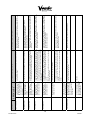
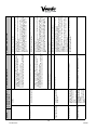
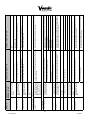
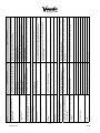
® SXY TROUBLESHOOTING SECTION Part #1167879 T-1 07/2008 PARTS RETURN PROCEDURES 1. All parts returned must be accompanied by a material return tags (P/N 1122825) Tag must clearly state the reason for the return and the Return Goods Authorization Number received from your Vendo Customer Service Rep at 1-800-344-7216. (Return tags are available from our parts department upon request). 2. All parts should be properly wrapped and packed securely to avoid further damage. 3. To replace an inoperative part, please use the following instructions 4. Complete the return tag making sure to fill in ALL requested information to ensure prompt processing. Keep top (white) copy for your records. Attach tag to inoperative part and send it by the most inexpensive method of transportation (Federal Express Ground or Overnight Transportation) To: SandenVendo America, Inc., 10710 Sanden Drive, Dallas, Texas 75238. 5. Be sure to check () the box marked “credit” and to fill in the invoice number covering the part sent to you or check the box marked “replace with like part”. 6. If the box is marked for replace with like part, a like part will be shipped at no charge if our inspection shows that the inoperative part became defective during the warranty period. 7. If the box is marked for credit, a credit will be issued to cancel the invoice on which the replacement part was shipped. This credit will include any applicable prepaid transportation charges. To receive credit the inoperative part must be returned within 30 days from the date the replacement was shipped. 8. Vendo does not issue cash credit for the return of any part or accessory. REFRIGERATION UNIT RETURN PROCEDURE 1. All refrigeration units returned must be accompanied by a material return tag (P/N 1122826). Tag must clearly state the reason for the return and the Return Goods Authorization Number received from your Vendo Customer Service Rep at 1-800-344-7216. (Return tags are available from our parts department upon request). 2. All refrigeration units should be properly wrapped and packed securely to avoid further damage. 3. To replace an inoperative part, please use the following instructions. 4. Complete the return tag making sure to fill in ALL requested information to ensure prompt processing. Keep top (white) copy for your records. Attach tag to inoperative part and send it by the most inexpensive method of transportation (Federal Express Ground or Overnight Transportation) To: SandenVendo America, Inc., 10710 Sanden Drive, Dallas, Texas 75238. 5. Be sure to check () the box marked “credit” and to fill in the invoice number covering the part sent to you or check the box marked “replace with like part”. 6. If the box is marked for replace with like part, a like part will be shipped at no charge if our inspection shows that the inoperative part became defective during the warranty period. 7. If the box is marked for credit, a credit will be issued to cancel the invoice on which the replacement part was shipped. This credit will include any applicable prepaid transportation charges. To receive credit the inoperative part must be returned within 30 days from the date the replacement was shipped. 8. Vendo does not issue cash credit for the return of any refrigeration unit. *Canadian and International customers please contact your Customer Service Representative for return instructions Part #1167879 T-2 07/2008 Part #1167879 T-3 07/2008 DESCRIPTION OF ERROR CODE Clamp motor portion of vending mechanism did not start or complete. Z motor portion of vending mechanism did not start or complete. Z-motor Jam Clamp-motor Jam Y motor portion of vending mechanism did not start or complete. X motor portion of vending mechanism did not start or complete. Y-motor Jam X-motor Jam Clamp motor has failed. Replace clamp motor. Look at clamp fingers to see if only partially open. Complete a test vend cycle of sold out products. If hand hits tray front, run Discovery 2. If hand jams on center gate, reduce Z Product Position by 3 encodings. If unit has returned to the home position, hand jammed but was able to recover. Check product positions to determine if any are sold out with product still in column. Replace fuse(s) if necessary. Plug in machine. Complete a test vend cycle. Remove product from hand. Unplug machine, wait 5 seconds and plug machine back in. If hand goes back home after auto recovery, run Z motor in Test Motors. Complete a test vend cycle. If product is in hand, look to see if product is stopping the hand from closing. Preform System Check, see X-Motor Jam. Unplug machine. Plug in Z housing ribbon cable. Plug machine back in. If hand goes back home after auto recovery, run Z motor in Test Motors. Complete a test vend cycle. If unit is extended in Z check Z housing ribbon cable to be sure it is plugged in. Complete a test vend cycle of sold out products. If hand hits tray in Y, run Discovery 2. If unit has returned to the home position, hand jammed but was able to recover. Check product positions to determine if any are sold out with product still in column. Replace fuse(s) if necessary. Plug in machine. Complete a test vend cycle. Clear jam, unplug machine, wait 5 seconds and plug machine back in. If hand goes back home after auto recovery, run Y motor in Test Motors. Complete a test vend cycle. If hand does not go home in Y, replace Y motor. If unit has not returned to the home position, check to see if hand is jammed on tray or other item in cabinet. Preform System Check, see X-Motor Jam. Replace fuse(s) if necessary. Plug in machine. Complete a test vend cycle. Complete a test vend cycle of sold out products. If hand hits tray in X, adjust X home position. Preform System Check, see X-Motor Jam. If unit has returned to the home position, hand jammed but was able to recover. Check product positions to determine if any are sold out with product still in column. Clear jam, unplug machine, wait 5 seconds and plug machine back in. If hand goes back home after auto recovery, run X motor in Test Motors. Complete a test vend cycle. If hand does not go home in X, replace X motor. If unit has not returned to the home position, check to see if hand is jammed on tray or other item in cabinet. CORRECTIVE ACTION Replace fuse(s) if necessary. Plug in machine. Complete a test vend cycle. CHECKING METHOD System Check: If unit does not move, check the LED in the lower left hand side of PDC. It should be a constant red light. If LED is not on, unplug machine, check fuse on power distribution panel. Check two pin power connector in bottom of door. Check connection to board on X rail. Check power connection in PDC. Check power supply connections in power distribution panel. Check LED on power supply in power distribution panel. Check fuse on power supply in power distribution panel. Vending Mechanism - PDC Error (Hand Control Board) ERROR Error Codes (version 15) The trouble shooting section contains Error Codes (version 15) and General Machine Troubleshooting. The SXY 30/40 vendor provides self-diagnostics to aid you in the trouble shooting process. Error codes are stored in the controller’s memory when a system error is sensed. These codes can be accessed in the Diagnostic section of Programming. Part #1167879 T-4 07/2008 During a target search operation, the Forward Looking Optic (FLO) was found to never activate. During a Discovery operation, 1) Check reflectors on top shelves. 2) Check all reflectors on an expected, required tray latch and hinge side trays are installed. reflector was not found Check power on the FLO device. The green light should be on. Test Flo with a corner-cube reflector piece. When the reflector is in front of the FLO, the second light should change from off to orange. Check top and bottom shelves are properly seated on the base metal. FLO Always Off Missing Coordinates Used in Discovery 3 and 4. A required tray is missing on the top or bottom shelf. During a Discovery operation, Check all tray positions. Make sure each tray has a corner-cube the number of shelves in the reflector in the center tray pocket. latch side did not match the Check all side trays are fully seated in shelves. shelves on the opposite side of the machine. During a Discovery operation, Check all tray positions. Make sure each tray is fully seated on one or more shelves was the shelf. found to vary in position more than 1 inch from the hinge side to the latch side. Missing Tray Shelf ends Mismatch Shelf Not Level Check all reflectors on top and bottom shelves. Check power on the FLO device. The green light should be on. Test Flo with a corner-cube reflector piece. When the reflector is in front of the Flo, the second light should change from off to orange. May not have seen any reflectors on latch side. Check reflectors along latch side trays. Reseat tray firmly in shelf. Reseat tray firmly in shelf. Run Discovery 2. Replace any missing tray reflectors. Run Discovery 2. Install any missing reflectors. If the green light is off, check the plug on the PDC. If the orange light does not turn on and off, replace the FLO assembly. If the Flo does turn on and off replace the PDC board. Reseat tray firmly in shelf Install any missing reflectors. If the green light is off, check the plug on the PDC. If the orange light does not turn on and off, replace the Flo assembly. If the Flo does turn on and off replace the PDC board. Make sure door properly closed. If the green light is off, check the plug on the PDC. If the orange light does not turn on and off, replace the FLO assembly. If the Flo does turn on and off replace the PDC board. Test Flo with a corner-cube reflector piece. The device has two lights. The green light should be on. When the reflector is in front of the Flo, the second light should change from off to orange. Check reflectors along latch side trays. FLO may have only seen the shelf 4 reflector during scan. Verify X Home aligned with latch side reflectors. During a target search operation, the Forward Looking Optic (FLO) was found to be always active. FLO Always On Remove the X-rail cap. On the latch side of the machine, release the Y gear coupling. Move the X-rail down until it is level. Recheck. Run Discovery 2. Unplug machine. Move the X rail manually to the center of the machine opposite a shelf. Close the door. Look along the bottom of the rail at the trays. Determine which side is higher. During a Discovery 2 operation, the X rail was higher on one side by more than 1 inch. X-Rail Not Level Check Motors Movement in Test Mode and regular Vending. Check all Sensors under Check Sensor Status. Install any missing reflectors. Depends on movement attempted. If Discovery, check reflectors. This is a non jam failure. A motor function failed to complete. Failed Movement Complete a test vend cycle of sold out products. If hand hits tray front, run Discovery 2. If hand jams on center gate, reduce Z Product Position by 3 encodings. CORRECTIVE ACTION Check product positions to determine if any are sold out with product still in column. CHECKING METHOD The unit encountered a jam condition while vending. It was able to recover from the jam and return to home. The user was requested to select a new product. DESCRIPTION OF ERROR CODE Jam - Recovered ERROR Part #1167879 T-5 07/2008 Test/Config Mode command PDC will automatically ignore the inappropriate command. received while not in Test/ Config Mode. Ex. Test Motors command received while the machine is vending. Inappropriate Command Run Discovery 2. If no changes were made to the trays/shelves in SXY, may indicate a missing reflector. Machine will automatically perform Discovery 2. Discovery 1 scanned the latch side of the SXY and the shelves discovered do not match those stored in FLASH. Shelf configuration changed. Failed Conformation 1) (In factory), if never able to program FLASH, the FLASH may be misconfigured (Fujitsu chip has Sector 7 protect on) 2) Random Failure: Cold reboot SXY and try again. 3) FLASH chip has failed or worn out (after many thousands of uses). Replace FLASH chip with new. The FLASH chip holds the software, so it is the PDC software chip. Don’t forget to save relevant parts of PDC’s configuration. 4) If FLASH chip change does not work (try more than once, using care to install chip without damage), there may be a failure in the PDC circuitry. Replace PDC board. Reboot the machine. Reboot the machine. If problem exists, change the PDC and VMC software. Unplug machine. Replace any malfunctioning motors or sensors. Plug the machine back in. If Green or Orange heartbeat, check MDB communication cable connections as above. If Red heartbeat, PDC has logic error. Unplug machine, wait 5 seconds and plug machine back in. If no heartbeat, LED is off and Flo power indicator is off, the PDC does not have power. Check the heartbeat on the VMC. If the VMC is powered, check the MDB cables. If no heartbeat and the Flo power indicator is on a problem with the software flash chip may be likely. Replace the flash chip. If this does not fix the problem, replace the PDC. Check LED’s on PDC. Lower right hand light should have heartbeat. Green heartbeat = PDC not receiving communication from VMC. Orange heartbeat = PDC both receiving and transmitting communication. Red heartbeat = PDC closed communication. No heartbeat (LED off or solid color LED) = PDC not operating. If no heartbeat, check Flo power indicator (should be solid green). Run Vending motors in Test Motor. Check health of sensors in Test Mode Check Sensors. Unplug machine. Reset any loose pins in harnesses. Reseat reseat harness plugs. Plug in machine. Check all harnessing between PDC and VMC. If Green or Orange heartbeat, check MDB communication cable connections as above. If Red heartbeat, PDC has logic error. Unplug machine, wait 5 seconds and plug machine back in. If no heartbeat, LED is off and Flo power indicator is off, the PDC does not have power. Check the heartbeat on the VMC. If the VMC is powered, check the MDB cables. If no heartbeat and the Flo power indicator is on a problem with the software flash chip may be likely. Replace the flash chip. If this does not fix the problem, replace the PDC. Check LED’s on PDC. Lower right hand light should have heartbeat. Green heartbeat = PDC not receiving communication from VMC. Orange heartbeat = PDC both receiving and transmitting communication. Red heartbeat = PDC closed communication. No heartbeat (LED off or solid color LED) = PDC not operating. If no heartbeat, check FLO power indicator (should be solid green). Changes to the configuration could not be stored in PDC’s FLASH chip. An error occurred that did not conform to any known error. Failed Unknown Unplug machine. Reset any loose pins in harnesses. Reseat reseat harness plugs. Plug in machine. CORRECTIVE ACTION Check all harnessing between PDC and VMC. CHECKING METHOD Setup Flash Write Failed / Setup Flash Write Failed PDC failed to communicate with VMC. DESCRIPTION OF ERROR CODE Failed Communication ERROR Part #1167879 T-6 07/2008 VMC will retry sending the command to PDC Test/Config Mode command received that is either an invalid comand number or has a parameter that is out of range for that parameter. A command was rejected because it is unsafe. A Test/Config Z Movement command was rejected because the PDC thinks the hand is in the pocket at the bottom of the machine. Command Data Out of Range Command Denied Safely Hopper flap motor either did not run, or no current was detected. VMC detected high current while running the Hopper Flap motor without detecting the Hopper flap positioning switch. Hop.Flap No Current Hopper Flap Jam Vending Mechanism - VMC Error 1.When any one of the folloing movements in X , Y , Z or Clamp fail during Test Motors. 2. When any of the sensors fails. ( i.e. X,Y, Z , Clamp or Forward Looking Optics Sensors ) TC Failed Movement If motor does not move, replace Hopper Flap motor. Remove the product. Run Hopper Flap Test. Check to see if product is jamming the Flap If motor moves, current detection circuitry has been damaged on VMC. Replace VMC board. Run Test Hopper Flap in Test Mode Plug in hopper flap connector. Run Test Hopper Flap in Test Mode. Run Test Hopper Flap in Test Mode Run Test Motors and Get Sensor Status after performing the checking method. Run Discovery 2 before performing Calibration or Corrections. CORRECTIVE ACTION Check Hopper flap harness connection. 1.Check to see if the X , Y , Z or Clamp movements are performed. On Exit from Test Motors the X,Y, Z and clamp should be at home position. 2.Check the Sensors. ( O denotes good sensor. If the sensor is blocked - then change the respective sensor ) Test/Config commands that Performing Calibrations / Set Z corrections without rumming have a shelf number as a discovery can lead to this error. parameter can return this error for a shelf number, while in range, which identifies a shelf that does not exist (was not found during discovery). Shelf Invalid PDC will automatically ignore the command. PDC will automatically ignore the command. Test/Config Mode command received while already executing a Test/Config command. Command in Progress CHECKING METHOD The MDB command received PDC will automatically ignore the command. is inappropriate for the current state of the PDC. Ex. example, if the Vend Drop command were received when the hand is not waiting at the hopper to drop a product during a Vend, Startup, or Recovery. DESCRIPTION OF ERROR CODE Command Out of Sequence ERROR Part #1167879 T-7 07/2008 Hopper bucket motor runs but Run Test Hopper Bucket in Test Mode does not detect the home switch. Hopper Bucket Switch Check the selection switch number shown in the detailed error code “nn” to see if: 1) if the Keypad is defective; 2) the harness is wired wrong/shorted Tube pay out jam -- reported by changer. Changer check sum incorrect -- reported by changer. Excessive escrow requests -- Check escrow lever and associated mechanisms. more than 255 requests since Close door then reopen. Check to see if error still occurs. the last coin was sensed. Coin jam - reported by changer Low acceptance rate -- coin acceptance has fallen below 80% Tube Jam Coin Read Only Memory Excessive Escrow Coin Jam Low Acceptance Clear tube blockage. If no blockage is found, replace changer. Replace acceptor. Replace transformer. If fuse is blown replace it. If light is not flashing, there is no power to board. Check and replug any unplugged connections. Try to correct the problem if one of the two items are found. If you can’t correct it, then replace the component in question. Replace the hopper bucket motor assy. Replace hopper flap motor assy. Drop coins test acceptance. Check changer/acceptor for obstructions or dirt Check changer/acceptor for jammed coins or other obstructions. If error does not clear, replace changer/acceptor. Unplug machine, wait at least five seconds, replug machine. Manually clear the error If no obstructions are apparent and coins do not accept, or acceptance rate is poor, replace changer/acceptor. If no obstructions are apparent, and acceptance appears to be OK, this may be an indication of cheating attempts. If no obstructions are apparent, replace changer/acceptor Replace changer/acceptor. Manually clear the lever and error. Replace acceptor Clear blockage, if found. If no blockage is found, replace changer. Check changer tubes and payout for blockage. Check inlet chute for blockage. Drop coins in Sales Mode or Tube Clear inlet chute blockage. If no blockage found, replace changer. If Fill Mode to test acceptance. Manually clear the error. acceptance rate is acceptable, system is OK. If acceptance rate is low or changer will not accept coins, replace changer. Changer inlet chute blocked - no coins sensed for over 96 hours by the changer. Coin Inlet Check changer tubes for blockage Tube sensor is defective -- reported by changer. Defective acceptor. Changer communication error Check that red light is flashing on control board. - no changer communication for more than 2 seconds. Check fuse on the power distribution panel. Bad Selection Switch - Selection switch within the Keypad is actuated for more than 15 seconds while in the Customer Mode or Door Open Sales Test Mode. Run Test Hopper Flap in Test Mode Tube Sensor Coin Communication Coin Changer Stuck Selection SW on Keypad Selection Switches - Keypad Hopper flap motor runs but does not detect the home switch. Remove the product. Run Hopper Bucket Test. Check to see if product is jamming the Bucket Hopper Flap Switch If motor does not move, replace Hopper Bucket motor. Run Test Hopper Bucket in Test Mode VMC detected high current while running the Hopper Bucket. If motor moves, current detection circuitry has been damaged on VMC. Replace VMC board. Run Test Hopper Bucket in Test Mode Hopper Flap Jam Plug in hopper bucket connector. Run Test Hopper Bucket in Test Mode. CORRECTIVE ACTION Check Hopper Bucket harness connection. CHECKING METHOD Hopper Bucket motor either did not run, or no current was detected. DESCRIPTION OF ERROR CODE Hop.Buck No Current ERROR Part #1167879 T-8 07/2008 Bill validator motor is reported No test available as defective by validator. Bill jammed -- reported by validator. Bill validator check sum is incorrect. Bill validator is open. Bill validator sensor is not functioning. Bill Validator Motor Bill Validator Jammed Bill Validator ROM Bill Validator Open Bill Validator Sensor Check seal around cabinet. Check harness to fan motor and check output voltage. Check if evaporator is frozen. Verify evaporator fan is running. Replace the door switch, if defective. Change settings as required. If the connection is unplugged, replug it. Check for temperature sensor connection J7 on control board is plugged in. Check refrigeration settings (refer to refrigeration section of programming manual). If the sensor is unplugged, replug it. Refer to card reader manual for corrective action. If there is a “rC” or “bC” error: 3) Check control board MdB harness. If there is no “rC” or “bC” error: 1) Check changer harness. 2) Replace changer. If no obstructions are apparent, replace bill validator. Check to see that temperature sensor harness is plugged into door harness at air dam area. No test available. Turn power switch off. Wait at least five seconds. Turn power switch on. Outer door has been open for Check the vendor’s door switch to see if it’s sticking or miswired. more than one hour. Miscellaneous Problems System has failed to decrease temperature 1° per hour while the compressor is running. Compressor Most recent “non-transient error” from the card reader. The temperature sensor is defective or unplugged. Door Switch Check bill validator for obstructions or dirt. If cashbox appears to be OK, replace bill acceptor. If error does not clear, replace bill acceptor. Turn power switch off. Wait at least five seconds. Turn power switch on. Manually clear the error. Check that bill cashbox is closed and in correct position. If no obstructions are apparent, replace bill validator. Replace bill acceptor. If cashbox appears to be OK, replace bill acceptor. If there are no “CC” or “rC” errors: 1) Check bill acceptor harness; 2) Replace bill acceptor. If there is a “C” or “rC” error: 1) Check control board MDB harness. If acceptor was set up correctly, replace acceptor. Correct connections. CORRECTIVE ACTION Check bill validator for obstructions or dirt. There is no card reader If card reader/bill acceptor is being used, check for “rC’ or “bC” communication for 5 seconds. errors. Temp Sensor Refrigeration Card Reader Card Reader Communication Card Reader Bill validator full - reported by validator (STACKER command). Bill Validator Full Insure bill cashbox is empty and that the cashbox is properly closed and in place. Bill validator communications If changer or card reader is being used, check for “CC” or “rC” - No bill validator errors. communication for 5 seconds. Turn off door switch and wait at least five seconds. Turn on door switch. Bill Validator Communication Dollar Bill Validator Coin routing - indicates a coin Verify acceptor set-up using manufacturer’s recommendations. was routed incorrectly. Routing Check coin mechanism plugs. Check for faulty harness wiring (see wiring diagram for circuit). CHECKING METHOD Disconnected acceptor -indicates that an acceptor is unplugged. DESCRIPTION OF ERROR CODE Accept Disconnect ERROR Part #1167879 T-9 07/2008 Check the connections of changer harness; make sure changer is Make corrections to harness or replace the changer if necessary. Scaling Factor error - one of the credit peripherals has plugged in and working. introduced a scaling factor that is not compatible with the current configuration. Machine’s coin inlet sensor is blocked for more than 1 minute. 3 successive coins are detected at the inlet but do not make it into the changer in 10 seconds. Inlet Sensor Escrow Return Mech. Replace harnesses or changer. Clear blockage or replace harness or changer. Check changer harnessing for cut, pinched or crimped wires. Check inlet for blockage. If nothing is found, check changer harnessing for cut, pinched or crimped wires. Contact a qualified electrician. Scale Check for low voltage at the wall outlet at unit start-up. AC voltage to the controller is less than 20Vrms for more than 30 seconds. If error shows up frequently, replace the control board. CORRECTIVE ACTION AC Low No test available. CHECKING METHOD Ram check sum for service mode settings stored in nonvolatile memory has been corrupted. DESCRIPTION OF ERROR CODE Ram Error ERROR Part #1167879 T-10 07/2008 PROBABLE CAUSE Bill Acceptor will not pull bill in. BILL ACCEPTANCE Changer will not payout coins. Always accepts coins but gives erratic/no credit. No acceptance or rejects a percentage of good coins. Coin mechanism will not accept coins. Make sure that the coin mech is plugged in (accepts coins) and that the coin tubes have enough coins to enable bill acceptance. Make sure that the changer harnessing is correctly connected and has continuity. Repair or replace if necessary. If acceptor accepts, bill acceptor was defective. Acceptance disabled by coin mech (if present), or bad harnessing. Coin mech is not operative. Replace acceptor and test. Enter the Service Mode or access the Coin Payout Mode. Changer payout buttons are disabled while door is closed or while in Open-Door Sales Mode. Unplug power. Wait for 10 seconds. Reconnect power and see if bill acceptor cycles. If not, check acceptor harnessing or replace the bill acceptor. If coin mech won’t payout coins manually in the Coin Payout mode or during the Sales Mode and the above two procedures have failed, replace the control board and test payout both in the Coin Payout mode and during a sale. Defective controller board. No power to validator. Replace coin mech and test. Defective coin mech. Replace/test controller. Test vendor’s manual coin payout. If vendor won’t pay out using the Coin Payout mode or during sales, check harness for cuts, bad continuity or wrong connections. If defective, replace and test. If NO CREDIT: Defective controller. Defective harness between coin mech and control board. Replace coin mech and test. Replace/test controller. Defective controller board. If ERRATIC OR NO CREDIT: Acceptor or coin mech. Contact manufacturer for tuning. Coin changer is improperly tuned (if tunable). Check harness for cut wires or wrong/bad connections. Test each wire for continuity or test to ground. If found to be defective, replace. Clean acceptor or contact dealer. Acceptor is dirty or foreign matter is in the path. If NO CREDIT: Defective harness between coin mech and control board (will have “CC” error). Make sure changer is mounted correctly and the coin return lever is in the proper position. Replace control board. Defective control board. Coin return lever pressing down on acceptor’s coin plunger. Replace coin changer/acceptor. Clean acceptor or contact your local coin mech dealer. Acceptor is dirty or other problem may exist (not tuned). Use a meter and check each wire for continuity and ground. Harness from coin mech to board is cut or disconnected. Short in coin mechanism. Check to make sure the red LED on the control board is flashing red. If flashing, check MDB harness connections. If connections are good, replace changer. CORRECTIVE ACTION No power to control board. COIN ACCEPTANCE/PAYOUT (Record all errors for reference if Vendo Technical Service is required) ERROR General Machine Troubleshooting Part #1167879 T-11 07/2008 No power or communication to hand. Tray or shelf out of position (not seated). Tray table in the PDC not present or correct. Vend flap motor umpluged or linkage broken. Product pusher not functioning No vend upon selection. Hand not aligned correctly to tray when vending. X-rail not moving, product in hand. Completely sold out while product is still in the column. Vendor accepts money but does not display credit. Replace changer. Replace board. Defective controller board. Replace control board. Defective controller board. Defective changer. Replace changer. Defective changer. If no light, replace control board. See “Tuning Changer”. Changer out of tune. Check for a flashing red light on control board. Vendor scrolls message on display but does not accept money. Check display and display harness. Replace if necessary. Defective display or display harness. No digital display; vendor lights on. If red light on control board is off, check fuse and transformer. Defective control board. Defective main harness. If door switch is replaced and still reading sold out, replace control board. Door switch wired incorrectly or cut/pinched. Display shows sold out immediately upon pressing selection button of full column (sold out not clearing). Vendor appears dead; no digital display and no lights. Manually press door switch. If still not vending, check wiring or replace door switch. Hand assembley hitting the lower blukhead. Tri-Teq lock system is in the locked position. Reposition y-rail stops and check y-home magnet. Open Tri-Teq lock, check for damage to lock slide. Check to see if product pusher is engaged. Test vend flap in Test Mode. Replace if broken. Reseat tray or shelf. Run calibration #1 then #2. Check for lights on hand. Left side red light (motor power) right side flashing (logicpower/ communication). If no light than check MDB connection on VMC. Enter Test Mode check Vend Detection (see service manual). Cycle power to unit. Strat-up routine should begin.Relpace/Test vend optics. Door will not close completely. MISCELLANEOUS PROBLEMS Vend optics blocked Hopper is open Access vendor configuration mode and check the “Forced Vend” setting. Controllers configurations not set properly. Cycle power to unit. Start-up routine should begin. Replace vend sensor. Both vend sensors are defective Communication error between VMC and PDC or PDC software error Replace/test controller for erasure of credit. Defective controller. Replace/test controller. Defective controller. Replace acceptor and test acceptance and erasure of credit. Replace/test acceptor. Defective acceptor. Defective bill acceptor. Make sure that the acceptor and harnessing is correct for your style of acceptor and it is plugged in and wired properly. CORRECTIVE ACTION Defective acceptor harness (credit not getting from acceptor to control board through the harness). PROBABLE CAUSE Hand not in home postion VENDING PROBLEMS Acceptor takes a bill and allows payback of coins without a selection. Bill acceptor takes a bill and credits but not erasing credit. Bill acceptor takes a bill but does not establish credit. ERROR Part #1167879 T-12 07/2008 Replace board. Defective controller board. Defective control board. No power to vendor. If unit still does not come on, then replace the control board. Defective control board. Compressor starts but does not run. Compressor will not start, condenser fan motor running - unit hot (power to compressor). Compressor will not start. Refrigeration unit runs constantly. Replace the PTC relay. Replace the refrigeration unit. Replace the refrigeration unit. Replace the over load relay. Defective PTC relay Smashed tubings and capillary Defective over load relay Replace the capacitor. Defective capacitor Loss of refrigerant Replace the refer unit. Compressor motor rocked Check for error codes. Replace cabinet switch. Replace the over load relay. Defective over load relay Defective cabinet switch. Defective relay - contacts are welded together. Check overload (apply insulated jumper across terminal, if compressor starts, replace overload). Replace control board. Replace relay. Defective control board. Overload protector inoperative. Upon opening the door, the display should read either errors, summary sales, or none. If it does not, then replace the cabinet switch. Upon opening the cabinet door, the lights and fans should shut off. If they don’t, replace the cabinet switch. Defective cabinet switch. Defective relay. Unplug unit at power distibution panel. Remove air dam. Reconnect power. Enable compressor relay through Test Mode. Check 2-pin connection on power distribution for 110V. Wait to see if unit comes on. Wait the 3 minute delay once the cabinet door is closed. Unit will not run in the compressor relay test Defective control board. mode. **NOTE: Leave the compressor relay test mode on, in order to check for voltage. Follow the same steps detailed above about the temperature sensor. Defective temperature sensor. Open and close the door to make sure lights and fan come on. If not, then check the cabinet switch. Check power supply, also check service cord connections. Replace board. 2. Replace temperature sensor. 1. Check connection. Repair or replace harness. Defective temperature sensor. Replace switch. Defective selection switch harness. CORRECTIVE ACTION Defective selection switch. PROBABLE CAUSE Unit will only run in the compressor relay test Defective cabinet switch. mode. (Located under Test Mode) Refrigeration unit will not run at all. Refrigeration unit will not run. REFRIGERATION Vendor accepts and credits money but does not vend (does not indicate a sold-out). ERROR Part #1167879 T-13 07/2008 Excessive noise. Product freezing up (too cold). Evaporator frosted over. Both compressor and condenser fan motors will not operate. Compressor runs but cabinet temperature warm. ERROR Replace the refrigeration unit. Make sure the drain hose is not kinked or clogged. Replace the temperature sensor. Make sure nothing is sitting in front of the evaporator. Replace the control board. Make sure the vend flap and gasket are not open. Defective drainage Defective temperature sensor Poor air flow Defective control board Defective door seal Replace the fan blade or re-install correctly. Re-install or replace the motor. Replace the refrigeration unit. Fan blade hitting shroud or transformation or loose fitting From the inside of fan motor or loose fitting From the inside of compressor or loose fitting Replace the control board. Check gasket, vend flap, and permagum on the bulkhead. Poor sealing Replace the temperature sensor. Replace the board. Defective control board Defective control board Replace the temperature sensor. Defective temperature sensor Defective temperature sensor Make sure the drain hose is not kinked or clogged. Re-install hose correctly if kinked or clogged. Defective drainage Adjust set point in control board. Replace the refer unit. Smashed tubings Temperature setting too low. Check wiring connections. Make corrections if necessary. Replace the refrigeration unit. Bad connection at power board. Loss of refrigerant Test relay using relay test function of the electronic controller. Replace relay if necessary. Bad refrigeration control relay. Defective heat exchange on condenser/ Blocking air Clean the surface of the condenser fins or straighten the bent fins. flow by dust, lint or fins damage Replace the refrigeration unit. Smashed tubings CORRECTIVE ACTION Loss of refrigerant PROBABLE CAUSE NOTES Part #1167879 T-14 07/2008