1
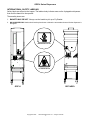
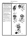
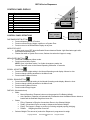
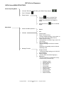
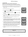
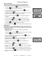
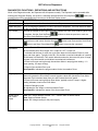
Models: GDF14, GDF14E and GDF14EL Fry / Appetizer Dispenser Equipment/Service Manual English (Rev. E) P/N 291508 Manufactured by AUTOMATED EQUIPMENT LLC 5140 Moundview Drive, Red Wing, MN 55066 U.S.A. PHONE: 1 (800) 248-2724 1 (651) 385-2273 FAX: 1 (651) 385-2166 SERVICE FAX: 1 (651) 385-2172 For Service in the US and Canada, Call: 1 (800) 248-2724 http:// www.autoequipllc.com Business Hours: 8:00 AM – 5:00 PM CST After hours, your call will be handled by a pager service; a Technical Support Representative will return your call. TABLE OF CONTENTS INTRODUCTION__________________________________________________________________________________________ 3 FCC STATEMENT ___________________________________________________________________________________________________ 3 SPECIFICATIONS ________________________________________________________________________________________ 3 WARRANTY _____________________________________________________________________________________________ 4 REQUESTING SERVICE, ASSISTANCE, OR PARTS ____________________________________________________________ 5 INTENDED USE __________________________________________________________________________________________ 6 SAFETY & EQUIPMENT CARE______________________________________________________________________________ 6 INTERNATIONAL SAFETY LABELING _______________________________________________________________________ 7 EQUIPMENT CARE LABEL ________________________________________________________________________________ 8 ASSEMBLING THE GDF14 DISPENSER ______________________________________________________________________ 9 ASSEMBLING THE GDF14E DISPENSER ____________________________________________________________________ 10 ASSEMBLING THE GDF14EL DISPENSER___________________________________________________________________ 11 DAILY SET UP __________________________________________________________________________________________ 12 DAILY CLOSING ________________________________________________________________________________________ 12 LOADING FROZEN PRODUCT INTO HOPPER ________________________________________________________________ 13 CONTROL PANEL DISPLAY ______________________________________________________________________________ 14 CONTROL PANEL DEFINITIONS ______________________________________________________________________________________ 14 GDF14 SERIES MENU STRUCTURE ________________________________________________________________________ 15 NORMAL OPERATING MODE _____________________________________________________________________________ 16 CHANGING THE DISPENSER WEIGHT SETTINGS _______________________________________________________________________ 16 EMPTY HOPPER MODE _____________________________________________________________________________________________ 17 USER MENU____________________________________________________________________________________________ 18 AUTO-MANUAL MODE ______________________________________________________________________________________________ 18 CALIBRATE MODE _________________________________________________________________________________________________ 19 MANAGER FUNCTION MODE _____________________________________________________________________________ 20 CONFIGURE PRESETS _____________________________________________________________________________________________ SELECT LANGUAGE _______________________________________________________________________________________________ DIAGNOSTICS ____________________________________________________________________________________________________ DIAGNOSTICS FUNCTIONS - DEFINITIONS AND INSTRUCTIONS___________________________________________________________ ERROR CODE DEFINITIONS _________________________________________________________________________________________ 20 21 21 22 23 TROUBLESHOOTING TABLE _____________________________________________________________________________ 24 BASKET SENSOR ADJUSTMENT __________________________________________________________________________ 25 ILLUSTRATIONS & PARTS LISTS __________________________________________________________________________ 27 FRONT VIEWS ____________________________________________________________________________________________________ REAR VIEWS______________________________________________________________________________________________________ SYSTEM SCHEMATIC ______________________________________________________________________________________________ CONTROLLER LAYOUT _____________________________________________________________________________________________ ACCUMULATOR DOORS ASSEMBLY __________________________________________________________________________________ ACCUMULATOR DRIVE ASSEMBLY ___________________________________________________________________________________ DRUM MOTOR DRIVE ASSEMBLY ____________________________________________________________________________________ BASKET RACK ASSEMBLY GDF14 ____________________________________________________________________________________ BASKET RACK ASSEMBLY GDF14EL _________________________________________________________________________________ Copyright © 2006 Automated Equipment LLC All rights reserved. 27 30 32 33 34 35 37 38 39 GDF14 Series Dispensers The information in this manual is subject to change without notice. IN NO EVENT WILL AUTOMATED EQUIPMENT LLC BE LIABLE FOR TECHNICAL OR EDITORIAL OMISSIONS MADE HEREIN; NOR FOR DIRECT, SPECIAL, INCIDENTAL, OR CONSEQUENTIAL DAMAGES RESULTING FROM THE FURNISHING, PERFORMANCE, OR USE OF THIS MATERIAL. This manual is copyrighted with all rights reserved. Under the copyright laws, this manual may not be copied, in whole or part, without the written consent of Automated Equipment LLC. Product names mentioned herein are for identification purposes only, and may be trademarks and/or registered trademarks of their respective companies. Copyright © 2006 Automated Equipment LLC 2 All rights reserved. GDF14 Series Dispensers INTRODUCTION SPECIFICATIONS The GDF14 Series Frozen Product Dispenser is a compact, semi-automated system that replaces manual basketing of Frozen Fries /Appetizers. There are two models in the Series: GDF14 and GDF14E. Features: • Bulk storage of frozen product: GDF14 - 36 lbs. / 16.3 kg GDF14E - 30lbs. / 13.6 kg GDF14EL - 30lbs. / 13.6 kg The GDF14 Series Frozen Product Dispenser weighs loads of frozen product and dispenses the selected weight into the Fryer Basket each time the Dispense button is pressed, or automatically dispenses when the Auto mode is activated. • • • The GDF14 Dispenser’s Hopper holds frozen product prior to Basket Loading. (See the Specifications for capacities. Capacity varies depending on the type and volume of the fry cut or appetizer.) A rotating Dispenser Drum inside the Hopper transfers the product onto the Accumulator Doors where a weighing system accurately weighs the frozen product. • Optional equipment: • • Fryer Baskets Side Basket Rack (holds 4 baskets) Electrical Requirements: • 120 V a.c., 60 Hertz, 0.75A, US/Canada • 95-240 V a.c., 50-60 Hertz, 40 Watts, 1Ø (single phase), International NOTE: This equipment is manufactured in the U.S., therefore all hardware measurements are in English, and the metric conversions stated are approximate. Other Equipment Information: • Noise Emissions: < 70 dB(A) • Maximum Altitude: 6000ft. (1525 meters) • Maximum Humidity: 95% non-condensing • Ambient Temperature: 40°- 77°F (4° 25°C) HAZARD COMMUNICATION STANDARD (HCS) The procedures in this manual may include the use of chemical products. These chemical products will be highlighted with boldface letters followed by the abbreviation (HCS) in the text portion of the procedure. See the HCS Manual for the appropriate Material Safety Data Sheets (MSDS). Serial Number: The information found in the serial number identification label on the back panel of the Dispenser is as follows: Example: s/n 14SR0006A00082 14S = Model GDF14 R = Plant 00 = Year of Manufacture 06 = Month of Manufacture A = Revision Level 00082 = Sequence number IMPORTANT This equipment is only to be installed in locations where use and maintenance is restricted to trained personnel. This equipment must be placed on a horizontal surface with a tilt of less than 2 degrees. FCC STATEMENT Space Requirements: Clear floor space near fry vat at least 15 inches (38 cm) wide and 28 inches (71 cm) deep. WARNING: This equipment generates, uses, and can radiate radio frequency energy and, if not installed and used in accordance with the instruction manual, may cause interference to radio communications. Copyright © 2006 Manual or Automatic Dispense Modes Electrically driven Holds 2 Fryer Baskets Disassembles for cleaning Automated Equipment LLC 3 All rights reserved. GDF14 Series Dispensers WARRANTY Automated Equipment LLC (hereinafter “AELLC”), warrants the purchased product to be free from manufacturing defects in material and workmanship under normal use and conditions for the period and component specified below: Components covered Electronic Circuit Board Assemblies Electrical and Mechanical Moving Parts Structural frame work or enclosures Crew removable components: • Crumb Tray • Basket Rack • Accumulator Tray • Hopper, Hopper Lid, Diverter • Drum • Fryer Baskets • Power Cord Term 1 year 1 year 1 year 90 days 90 days 90 days 90 days 90 days 90 days 90 days The Warranty period commences on the date of shipment from AELLC for the Frozen Product Dispenser and/or Dispenser Accessories (hereinafter “Product”). EXCEPT AS OTHERWISE PROVIDED HEREIN AELLC MAKES NO OTHER WARRANTIES, EXPRESSED OR IMPLIED AND SPECIFICALLY DISCLAIMS ANY WARRANTY OF MERCHANTABILITY OR FITNESS FOR A PARTICULAR PURPOSE. AELLC shall not be liable for any direct, indirect, consequential damages (including damages for loss of business profits, business interruption, loss of business information and the like) arising out of the use of or inability to use the Product. THIS WARRANTY IS VOID IF THE PRODUCT IS NOT FUNCTIONING CORRECTLY DUE TO ABUSE OR NEGLECT BY THE PURCHASER, ITS EMPLOYEES, AGENTS, OR OTHER REPRESENTATIVES EITHER BY BREAKING, BENDING, MISUSE, ABUSE, DROPPING, ALTERATION, IMPROPER MAINTENANCE OR ANY OTHER FORM OF NEGLECT OR IMPROPER USAGE. THIS WARRANTY DOES NOT COVER DAMAGE TO THE PRODUCT CAUSED BY NATURAL CAUSES SUCH AS LIGHTNING, ELECTRICAL CURRENT FLUCTUATIONS, FLOOD, FIRE, TORNADOES, OR OTHER ACTS OF GOD. AELLC WILL INVOICE PURCHASER FOR REPAIRS MADE NECESSARY BY THE HEREIN LISTED CAUSES. This warranty is governed by the substantive laws of Minnesota, U.S.A., without giving effect to the conflict of law provisions. This warranty is non-transferable and applies only to the original Purchaser. Copyright © 2006 Automated Equipment LLC 4 All rights reserved. GDF14 Series Dispensers REQUESTING SERVICE, ASSISTANCE, OR PARTS WARRANTY SERVICE Warranty service must be initiated by calling AELLC’s Technical Support Hot Line at 1-800-248-2724 (U.S./Canada) or 651-385-2273 to establish all warranty requests. When repairing this unit, use only replacement parts supplied by AELLC, or supplied by an AELLC Factory Authorized Parts Distributor. Use of replacement parts other than those supplied by AELLC or by an AELLC Factory Authorized Parts Distributor will void the warranty. AELLC Technical Support personnel will determine the cause of failure and provide the appropriate resolution. If replacement parts are required, parts will be provided by AELLC or by an authorized Service Support Center/Parts Distributor. All charges for parts and shipping are F.O.B. AELLC, and are subject to change without notice. Prices will be those in effect at the time of shipment. Schwan's Technology Group, Inc. reserves the right to make suitable substitutions in materials, depending upon their availability. NON-WARRANTY SERVICE Service is normally conducted by customer appointed personnel, or by contracting a local service agent. Service fees are in accordance with industry standards. Replacement parts are available through local Service Support Center/Parts Distributors or direct from AELLC by calling 1-800-248-2724 (U.S./Canada) or 651-385-2273 in the event a local distributor is not available. WARNING! Only trained and/or qualified personnel should perform service to this equipment. AELLC's Technical Support Hot Line is available for telephone assistance providing AELLC product technical support, parts and parts information, and service agent referral. Contact AELLC’s Technical Support Hot Line at 1-800-248-2724 (U.S./Canada) or 651-385-2273. Service functions described in this manual could cause irreversible damage to the equipment and/or injury to personnel if performed improperly. If the power cord is damaged, it must be replaced by the manufacturer or its service agent or a similarly qualified person in order to avoid a hazard. Record the following information for your records: Date of Installation Service Agency Telephone Serial Number Copyright © 2006 Automated Equipment LLC 5 All rights reserved. GDF14 Series Dispensers INTENDED USE The GDF14 Series Dispenser is intended to dispense only non-meat based frozen food products. NOTICE: • The Dispenser must be accessible from the rear for service. • The Dispenser must be accessible from all sides for routine cleaning and maintenance. A minimum of 4 inches (10cm) clearance on both sides and behind the Dispenser is recommended. SAFETY & EQUIPMENT CARE Follow these guidelines during operation and repair of the GDF14 Series Frozen Product Dispenser: • Disconnect the Dispenser Power Cord from the wall outlet before servicing. • If the power cord is damaged it must only be replaced by the manufacturer or its service agent, or by a similarly qualified person, in order to avoid a hazard. • Use appropriate tools for servicing this equipment. • Inspect the Dispenser on a regular basis to identify problems before they occur. • Keep the Dispenser clean. • Keep hands away from the following areas while the Dispenser is operating: Accumulator Doors Dispenser Drum • Fryer baskets may be hot. Pick up by handles only. • Do NOT spray down the Dispenser with water. The Dispenser is not sealed against jetting water; therefore contaminants and moisture may get into sensitive components. • Do NOT roll the Dispenser to the back sink for cleaning; this will cause unnecessary wear on the Dispenser. • Do NOT place the Dispenser in the freezer to maintain product. Always remove product from the Dispenser at the end of each day. WARNING! Only trained and/or qualified personnel should perform service to this equipment. Service functions described in this manual could cause irreversible damage to the equipment and/or injury to personnel if performed improperly. Copyright © 2006 Automated Equipment LLC 6 All rights reserved. GDF14 Series Dispensers INTERNATIONAL SAFETY LABELING Safety labels are affixed to the hopper. The labels clearly indicate areas on the fry/appetizer dispenser that could be harmful to the operator. These safety issues are: 1. BASKETS MAY BE HOT: Always use the handle to pick up a Fry Basket. 2. NO HANDS BELOW: Hands should not be placed near or below the accumulator doors while the dispenser is energized. BASKETS MAY BE HOT NO HANDS BELOW GDF14 GDF14E/EL Copyright © 2006 Automated Equipment LLC 7 All rights reserved. GDF14 Series Dispensers EQUIPMENT CARE LABEL The label affixed to the side of the Controls cabinet warns against actions that may cause damage to the Dispenser. Failure to abide by these label instructions will void the warranty if the machine is damaged. GDF14 GDF14E/EL DO NOT SPRAY DISPENSER TO CLEAN Copyright © 2006 DO NOT STORE DISPENSER IN FREEZER Automated Equipment LLC 8 DO NOT ROLL DISPENSER ACROSS UNEVEN SURFACES All rights reserved. GDF14 Series Dispensers ASSEMBLING THE GDF14 DISPENSER 1. Turn the Hopper (Item 1) upside down with the window facing forward. Place the Drum (Item 2) into the Hopper. The end of the Drum with the square hole must face the back of the hopper. The ends of the Drum fit into round indentations on the inside of the hopper. Once the Drum is in place, the Drum Pin (Item 3) is inserted into the hole on the front of the Hopper and the thumbscrew tightened down. Check that the Drum turns freely before continuing. 2. Turn the Hopper upright to install the Diverter (Item 4). The Diverter has two outer holes that have right angle slots. The round part of the outer holes fits over shoulder bolts (Item 5) on the inside left of the Hopper. After the Diverter has been placed on the shoulder bolts, slide it down and then to the left to fit the shoulder bolts into the right angle slot. The two inner holes on the Diverter are provided as finger grips to help guide the Diverter into the correct position. 3. Mount the Basket Rack (Item 6) onto the Shoulder Bolts on the Dispenser Chassis. 4. Place the Accumulator Tray (Item 7) onto the Accumulator Doors. The wider end/larger opening is the topside of the Tray. The Accumulator Tray has two parallel grooves to fit directly and securely on the Accumulator Door Shaft bars. 5. Grasp the front of the Hopper where indicated by the arrows to mount the Hopper to the Support Bars. Slide the Hopper onto the Hopper Support Bars aligning the Drum Motor shaft with square hole in the Dispenser Drum. It may be necessary to manually rotate the Drum to attain proper alignment between the Drum and the Drum Motor Shaft. Do this by sliding your hand under the Hopper between the Hopper and Accumulator Tray. You will feel the Drum align on the shaft as you manually rotate the drum. Once the Drum Motor Shaft and Drum are properly aligned, slide the Hopper completely onto the Dispenser Chassis. Apply gentle pressure to the Hopper to fully engage the Hopper onto the Hopper Support Bars. CAUTION: Do NOT force the Hopper back, damage to the Hopper or Drum could occur. 6. Slide the Crumb Tray (Item 8) under the Basket Rack. Install the Hopper Lid (Item 9). Copyright © 2006 Step 1 Step 2 Step 3 Step 4 Step 5 Automated Equipment LLC 9 Step 6 All rights reserved. GDF14 Series Dispensers ASSEMBLING THE GDF14E DISPENSER 1. Find the square opening in one end of the Dispenser Drum (Item 1). Place the Dispenser Drum in the Hopper (Item 2), aligning the square opening on the Dispenser Drum with the hole in the back of the Hopper. 2. Grasp the Hopper (where indicated by the arrows) so that the hole is toward the Dispenser. Align the indentations on the sides of the Hopper with the Hopper Support Bars (Item 3). Push the Hopper onto the Hopper Support Bars until the Drum Motor shaft touches the Dispenser Drum. CAUTION: Do NOT force the Hopper back, you could damage the Hopper or Drum. Step 1 Step 2 Rotate the Dispenser Drum (CLOCKWISE or COUNTERCLOCKWISE) while applying gentle pressure to the Hopper until you can easily slide the Hopper fully onto the Hopper Support Bars 3. Place the Diverter (Item 4) in the Hopper. Be sure that it is hooked on the LEFT edge of the Hopper. 4. Mount the Basket Rack (Item 5) onto the Shoulder Bolts on the Dispenser Chassis. 5. Slide the Crumb Tray (Item 6) under the Basket Rack. Install the Hopper Lid (Item 7). Step 3 Step 4 Step 5 Copyright © 2006 Automated Equipment LLC 10 All rights reserved. GDF14 Series Dispensers ASSEMBLING THE GDF14EL DISPENSER 1. Find the square opening in one end of the Dispenser Drum (Item 1). Place the Dispenser Drum in the Hopper (Item 2), aligning the square opening on the Dispenser Drum with the hole in the back of the Hopper. 2. Grasp the Hopper so that the hole is toward the Dispenser. Align the indentations on the sides of the Hopper with the Hopper Support Bars (Item 3). Push the Hopper onto the Hopper Support Bars until the Drum Motor shaft touches the Dispenser Drum. CAUTION: Do NOT force the Hopper back, you could damage the Hopper or Drum. Step 1 Step 2 Rotate the Dispenser Drum (CLOCKWISE or COUNTERCLOCKWISE) while applying gentle pressure to the Hopper until you can easily slide the Hopper fully onto the Hopper Support Bars 3. Place the Diverter (Item 4) in the Hopper. Be sure that it is hooked on the LEFT edge of the Hopper. 4. Mount the Basket Rack (Item 5) onto the Shoulder Bolts on the Dispenser Chassis. 5. Slide the Crumb Tray (Item 6) under the Basket Rack. Install the Hopper Lid (Item 7). Step 3 Step 4 Step 5 Copyright © 2006 Automated Equipment LLC 11 All rights reserved. GDF14 Series Dispensers DAILY SET UP DAILY CLOSING 1. Make sure the Power Switch is OFF. 1. Remove all Fryer Baskets from the Dispenser. 2. Assemble the Dispenser (see pages 9 - 10). 2. If the Hopper and/or Accumulator Doors are not empty select the Empty Hopper mode 3. Plug the Power Cord into a wall outlet. 4. Turn ON the Dispenser. Depending on the previous operation, the Dispenser will be in either Normal Operating mode or Automatic Operation mode. using the Scroll Down button on the Control Panel. Press the Dispense button to empty remaining product into the waiting basket. 5. Fill a Fryer Basket by placing it under the Accumulator Doors and pressing the Dispense button. When in Auto mode the Dispenser will automatically fill the basket when it is placed under the Accumulator Doors and is detected by the Basket Sensor. The Red Indicator Light on the Control Panel turns OFF (does not illuminate) when it detects a basket in proper position. The Light illuminates when the Dispenser delivers a basket load. 3. Turn the Power Switch to the OFF position. 4. Disconnect Power Cord from the electrical outlet. 5. Remove the Hopper, Lid and Drum assembly. 6. Remove the Accumulator Tray, Basket Rack and Crumb Tray. 7. Take removable components from the Dispenser to the washing area. Wash them in a hot solution of sanitizing solution and water, rinse in clear water and allow to air dry (wash /rinse/sanitize). WARNING: The Drum, Hopper, Hopper Lid, Accumulator Tray, Crumb Tray and Fry Diverter are NOT dishwasher safe. 8. Wipe down the Dispenser with a hot solution of sanitizing solution and water. Repeat wipe-down with clear water and allow to air dry. WARNING: Do NOT spray down the Dispenser with water. The Dispenser does not provide an airtight seal. Contaminants and moisture may get into sensitive components. 9. Move the Dispenser out from the wall to clean behind and underneath it. WARNING: Do NOT move the Dispenser to the back sink for cleaning, this will cause unnecessary wear on the Dispenser. 10. Dry all parts and reassemble the Dispenser. 11. Roll the Dispenser back into place. Copyright © 2006 Automated Equipment LLC 12 All rights reserved. GDF14 Series Dispensers LOADING FROZEN PRODUCT INTO HOPPER To achieve optimum yield and the most consistent basket loads, it is important to use the following technique for loading frozen product into the Hopper. (See Specifications on page 3 for Hopper capacities. Capacity varies depending on the type and volume of the fry cut or appetizer.) For each bag or box of frozen product: 1. Remove the bag or box of product from the case. Be careful not to crush the product. 2. Open the top of the bag or box completely. If your supplier uses bags, make sure the bag top is fully open. If it is partially open, the product may be retained by the bag. WARNING PINCH HAZARD Personnel should take care not to place hands or fingers near the Drum, inside the Hopper, while this machine is in operation. Hands or fingers could be pinched between the Drum and the Hopper as the Drum turns. 3. Hold the opened end of the box or bag closed with your hand and lay the opened end of the bag or box into the bottom of the Hopper against the wall opposite the Diverter. 4. Release the opened end of the bag or box. 5. Empty the bag or box into the hopper by pulling it evenly toward the Diverter. When adding multiple bags of fries, alternate the placement of the bag or box in the hopper opposite of the previous bag or box. The second bag of product should be emptied into the Hopper with the opening toward the Diverter, pulling it evenly toward the Hopper Wall opposite the Diverter, leaving a uniform layer of product. Repeat steps 1 through 5 until the Hopper is full. NOTE: Do NOT fill the Hopper past the top. NOTE: This criss-cross loading method assures an even distribution of varying length product in the Hopper and the Baskets. NOTE: To reduce product breakage, do NOT shake or drop product from the bag or box into the Hopper. 6. Close the Lid on the Hopper. Copyright © 2006 Automated Equipment LLC 13 All rights reserved. GDF14 Series Dispensers CONTROL PANEL DISPLAY 4 Item Description 1 2 3 4 5 6 7 8 9 10 3 Dispense/Reset button Indicator Light Menu/Enter button Scroll Up button Scroll Down button Display Screen Mode Selected Weight Status: Accumulator Doors are filling Status: Ready to Dispense 5 2 Auto Operation 1.0 Lb 1 Ready 6 7 Auto Operation 1.0 Lbs Filling CONTROL PANEL DEFINITIONS Auto Operation 1.0 Lbs 8 DISPENSE/RESET BUTTON: • Press to dispense a load of Product. • Press to reset an Empty Hopper condition or a System Error. • Press to return to the Default/Main Display at any time. Ready 9 10 INDICATOR LIGHT: • In Auto mode, turns OFF when the Basket Sensor detects a Basket. Light illuminates again after Accumulator dispenses load. • Flashes fast when a System Error occurs, flashes slow when the Hopper is empty. MENU/ENTER BUTTON: • Press and hold to open a Menu mode. • Press to enter a Menu Option. NOTE: Once in the Menu mode, if no further changes are made, the Control Panel will return to the Normal Operating mode after 10 seconds. SCROLL UP BUTTON: • Press to increase weight setting in the Normal Operating mode display: Manual or Auto. • Press to change a Menu parameter in the Menu mode. • Press to select a Menu function. SCROLL DOWN BUTTON: • Press to decrease weight setting in the Normal Operating mode display: Manual or Auto. • Press to change a Menu parameter in the Menu mode. • Press to select a Menu function. • Press to select Empty Hopper. DISPLAY: (Illustrated above) • Mode: • Manual Operation: Dispense button must be pressed to fill a Basket (default). • Auto Operation: Dispenser will automatically fill a Basket when the Basket Sensor detects a basket and the Selected Weight has been met. • Status: • • • • • Filling: Dispenser is filling the Accumulator Doors to the Selected Weight. Ready: Accumulator Doors are ready to dispense the Selected Weight. Empty: The Hopper is Empty or product is not being weighed properly (bridging). Disable: Weighing has been turned off. Selected Weight: The amount of product the Dispenser is programmed to weigh. Copyright © 2006 Automated Equipment LLC 14 All rights reserved. GDF14 Series Dispensers GDF14 Series MENU STRUCTURE Normal Operating Mode Menu Mode • Increase / Decrease Weight Setting, and Select Empty Hopper. • Push To Dispense • Empty Hopper • • button to activate Drum Press the rotation and open Accumulator Doors; continue to press button until Hopper is empty. Press the Scroll Up weight. Manual Auto “Zeroing scale” “Place 1.00 lbs./0.50 kg.” (Position weights precisely, front to back, on the center of the Accumulator Doors.) “Place 2.00 lbs./1.00 kg.” (Add additional 1.00 lbs/0.50 kg to total 2.00 lbs/1.00 kg.) “Remove Weights” (Remove all weight from the accumulator doors.) Dispenser automatically returns to Normal Operating mode. Select Auto/Man Operation Calibrate • button to selected Manager Function Configure Preset (Customize weight settings by 0.10 lb/0.05 kg increments.) Select Language (Scroll to enter the desired language.) Diagnostics This set of functions is intended for use by trained service personnel only. Copyright © 2006 Automated Equipment LLC 15 Software Version Disable Weighing Error Counts Clear Errors Accumulator Weighing System Sensor/ Power Weighing Values Exercise Mode Restore Defaults All rights reserved. GDF14 Series Dispensers NORMAL OPERATING MODE When the Dispenser is turned ON it will automatically be in the Normal Operating mode. (See Illustration on page15) It will be in either Manual or Auto mode. Initially (if there is no product on the accumulator doors), the Drum motor will begin to turn and the Display will indicate that the Dispenser is FILLING the Accumulator Doors. If the Weight Sensor does not detect product on the Accumulator Doors to meet the weight setting after 40 seconds, the Dispenser will assume there is a problem with the product (bridging) in the Hopper or that the Hopper is empty. The Indicator Light will begin to blink slowly (1 blink per second) and the Display will indicate that the Hopper is Empty. To correct this condition, check the Hopper for product bridging (there is a sufficient amount of product in the Hopper, but fries or other food product have clumped together, forming a bridge, so that the product is not falling onto the Drum or Accumulator Doors) or refill it and then press the Dispense/Reset button. Auto Operation 1.00 lbs Filling Auto Operation 1.00 lbs Empty NOTE: The drum will automatically start turning after 90 seconds if the dispense/Reset button is not pressed.) After sufficient product is dispensed on to the Accumulator Doors to satisfy the Weight Sensor, the Display will indicate that the Dispenser is Ready to deliver the product into a Fryer Basket. Auto Operation 1.00 lbs Ready Fill a Fryer Basket by placing it under the Accumulator Doors. In the Auto mode, product is automatically delivered into a Fryer Basket when the Basket is placed under the Accumulator Doors. Slide the Basket back toward the Dispenser Chassis. The Indicator Light will go OFF when the Basket is detected by the Optical Basket Sensor. After half a second, the Accumulator Doors will cycle to deliver the product into the Basket. The Indicator Light will then come back on. In the Manual or Auto mode, pressing the Dispense/Reset button will also deliver the product into the Basket. CHANGING THE DISPENSER WEIGHT SETTINGS While in the Normal Operating mode the operator can easily change the Dispenser weight settings. button or Scroll Down button to select the preset Press the Scroll Up weight settings. These values will be shown on the display screen. The preset default weight selections are 0.50 lb/0.25 kg, 1.00 lb/0.50 kg, 1.50 lbs/0.75 kg and possibly 2.00 lbs/1.00 kg. The basket weight can be adjusted by 0.10 lb/.05 kg increments. If the new weight selection is increased from the previous selection, the Drum will turn to achieve the new increased weight before delivering a basket load. If the new weight selection is decreased from the previous selection, the previous (higher) weight is already “waiting” on the Accumulator Doors. The “waiting” amount must be dispensed into a basket. After delivery, the Dispenser will dispense the newly selected weight. Copyright © 2006 Automated Equipment LLC 16 All rights reserved. Auto Operation 1.50 lbs Ready GDF14 Series Dispensers EMPTY HOPPER MODE Press the Scroll Down button to access the Empty Hopper function. NOTE: Be sure to have an empty basket under the Accumulator Doors before continuing this procedure. Press the Dispense/Reset button and hold to activate the Drum rotation and open the Accumulator Doors to empty the Hopper. Continue holding the button until the Hopper is empty of all product. The button can be released and pressed repeatedly until the Hopper is empty. button to return to desired weight. The Dispenser will revert to the previously selected Press the Scroll Up Auto or Manual mode operation. Copyright © 2006 Automated Equipment LLC 17 All rights reserved. GDF14 Series Dispensers USER MENU 1. Press and hold the Menu/Enter Down button and, at the same time, press the Scroll button to access the Menu mode. MENU MODE PROGRAMS 2. Scroll through the available Menus by pressing the Scroll Up /Down buttons. NOTE: The available Menus (Auto-Manual, Calibrate, and Manager Functions) will blink until an option is selected. Once in the Menu mode, if no further changes are made, the Control Panel will return to the Normal Operating mode after 10 seconds. 3. Once the desired menu is visible on the display screen, press the Menu/Enter - Auto – Manual Mode - Calibrate Mode - Manager Function Mode button to enter the desired function. AUTO-MANUAL MODE Use the following procedure to program the Dispenser for Auto or Manual Mode: 1. Press and hold the Menu/Enter Scroll Down Select Auto/Man Manual button and, at the same time, press the button to access the MENU mode. 2. Press the Menu/Enter 3. Use the Scroll Up “Auto” and “Manual”. button once to enter the Auto/Man mode. button or the Scroll Down button to change between button must be pressed to NOTE: In the Manual mode the Dispense/Reset deliver a basket load. In the Auto mode, automatic delivery occurs when the Basket Sensor detects a basket in proper position under the Accumulator Doors. button to set the desired selection. Doing so will return 4. Press the Menu/Enter the Dispenser to the Normal Operating mode. Depending on your selection, the Dispenser is ready to fill baskets manually or automatically. OR button to return the Dispenser to the Normal Press the Dispense/Reset Operating mode without any changes in programming. Copyright © 2006 Automated Equipment LLC 18 All rights reserved. Auto Operation 1.00 lbs Filling GDF14 Series Dispensers CALIBRATE MODE This mode is used to calibrate the Dispenser weighing system. Note: Remove the Hopper and any product from the Accumulator Doors prior to performing this procedure. DO NOT remove the Accumulator Tray on the GDF14. Program the Dispenser for the CALIBRATE mode using the following procedure: 1. Restore defaults. (This function is accessed via the Diagnostics Mode. (See pages 15, 21-23). Calibrate 2. Select Language (see Select Language, page21). 1.00 lbs Ready 3. Press and hold the Menu/Enter Down button and, at the same time, press the Scroll Calibrate button to access the MENU mode. Zeroing Scale 4. Scroll through the MENU by pressing the Scroll Down is displayed. button until "Calibrate" button once to enter the Calibrate mode. This will 5. Press the Menu/Enter begin the calibration process and instructions will be prompted on the display screen. 6. The message “ZEROING SCALE” will appear on the display screen. The Accumulator Doors will open and close. Calibrate 7. The Dispenser will automatically advance to the “PLACE 1.00 LB” (or "0.50 kg" if in the metric mode) prompt. At this point the operator is to place a 1.00 lb./0.50 kg weight on the Accumulator Doors. NOTE: Make sure the weight is placed in the center of the Accumulator Doors, front to back. Place 1.00 lb 8. The Dispenser will advance to the “PLACE 2.00 LB” (or "1.00 kg" if in the metric mode) prompt. At this point the operator is to place an additional 1.00 lbs./0.50 kg of weight on the Accumulator Doors, for a total of 2.00 lbs./1.00 kg. NOTE: Make sure the weight is placed in the center of the Accumulator Doors, front to back. Place 2.00 lb 9. After the calibration weight is detected, the Dispenser will prompt the operator to “REMOVE WEIGHT”. Remove all weight from the Accumulator Doors. The Dispenser will automatically return to the Normal Operating mode. Remove Weight Calibrate Calibrate 10. Turn Dispenser power OFF for 15 seconds. Complete assembly and resume operation. SERVICE NOTE Calibration must be performed anytime a controller pcb, e-prom or NCWS component is replaced. Copyright © 2006 Automated Equipment LLC 19 All rights reserved. GDF14 Series Dispensers MANAGER FUNCTION MODE CONFIGURE PRESETS This mode is used to adjust the preset weight values for use in the Normal Operating mode by the Dispenser operator functions (see page16). Program the Dispenser for the CONFIGURE PRESETS using the following procedure: 1. Press and hold the Menu/Enter Down button and, at the same time, press the Scroll Configure Preset 1.00 lb Ready button to access the MENU mode. 2. Scroll through the MENU by pressing the Scroll Down Function" is displayed. button until "Manager button once to enter the Manager Function mode. 3. Press the Menu/Enter NOTE: Each Menu description will blink until it is entered. button once to access the Configure Preset program. (Press the Menu/Enter Pressing the Menu/Enter button will start the Configure Presets process and instructions will be prompted by the display.) 4. The Display shows that the weight in position 1 (POSN 1) is set at 0.50 lb (or 0.25 kg if in the metric mode). The number 1 will be flashing. button or Scroll Down 5. Use the Scroll Up on positions 2, 3 and possibly 4. Posn 1 Target 0.50 lb button to observe the settings Posn 1: to enter the weight setting function. 6. To change position target weight, press Notice the weight setting will now begin to flash. button or Scroll Down button to increase or 7. Press the Scroll Up decrease the setting in 0.10 lb/.05 kg increments. One press of either scroll button equals 0.10 lb/.05 kg increments. button will set the new value 8. Once the new weight is selected, pressing the into memory. The Position number will resume flashing. 9. Repeat steps 6 through 9 until all settings are correct. 10. Press the Dispense/Reset button to return to the Normal Operating mode. NOTE: To exit Configure Presets without making or saving changes, press Dispense/Reset button. Copyright © 2006 Automated Equipment LLC 20 All rights reserved. Target 0.50 lb GDF14 Series Dispensers SELECT LANGUAGE This mode is used to select the language used on the Display Panel. Select the preferred display language using the following procedure: button and, at the same time, press the 1. Press and hold the Menu/Enter Scroll Down button to access the MENU mode. 2. Scroll through the MENUS by pressing the Scroll Down "Manager Function" is displayed. Select Language button until button once to enter the Manager Function mode. 3. Press the Menu/Enter NOTE: Each Menu description will blink until it is entered. 4. Scroll by pressing the Scroll Down displayed. button until "Select Language" is 1.00 lb Ready Select Language English button to enter the Select Language mode. 5. Press the Menu/Enter or Scroll Down button to choose a language. 6. Press the Scroll Up 7. Once the desired language is displayed on the display screen, press the Menu/Enter button to set the language into memory. 8. Press the Dispense/Reset button to return to the Normal Operating mode. DIAGNOSTICS This mode is used to select the Diagnostic function, and should be used by trained personnel only. Select the preferred Diagnostic function using the following procedure: NOTE: See Pages 22 and 23 for a list of functions available in the Diagnostics mode 1. Press and hold the Menu/Enter Scroll Down button and, at the same time, press the button to access the MENU mode. 2. Scroll through the MENUS by pressing the Scroll Down "Manager Function" is displayed. button until 3. Press the Menu/Enter button once to enter the Manager Function mode. NOTE: Each Menu description will blink until it is entered. 4. Scroll by pressing the Scroll Down displayed. button until "Diagnostics" is button to enter the Diagnostics mode. 5. Press the Menu/Enter 6. Press the Scroll Up or Scroll Down button to choose a Diagnostic function. 7. Once the desired Diagnostic function is displayed on the display screen, press the Menu/Enter button to set the Diagnostic function into memory. 8. Press the Dispense/Reset mode. button to return to the Normal Operating Copyright © 2006 Automated Equipment LLC 21 All rights reserved. Diagnostics 1.00 lb Ready GDF14 Series Dispensers DIAGNOSTICS FUNCTIONS - DEFINITIONS AND INSTRUCTIONS While in the Diagnostics mode, the Dispenser will still operate normally. The Dispenser can be operated while watching the Diagnostic Display. If a function is manually operated with the Scroll Up/Down normal function will be suspended until returning to the Normal Display screen. FUNCTIONS DESCRIPTIONS buttons, the Software Version Displays the version of software installed in the Dispenser. Disable Weighing Turns off weighing mechanism in order to service the Dispenser. The Drum does not rotate, but the Accumulator Doors still activate. Records the number of errors per error code. Displays two rows, each containing three sets Error Counts of numbers. Use the Scroll Up/Down (See Error Code Definitions page 23). Clear Errors Clears all error code counts. Use the Scroll Up button to set Save. Press Menu/Enter Accumulator buttons to show the previous or next row. button to set Clear and the Scroll Down button to execute the command. H: Home Sensor. ON = doors are shut. OFF = doors are not fully shut. M: Accumulator Motor Drive output. ON = output on. OFF = output off. T: Indicates half the time for a full door cycle (time lapse for Accumulator Doors to close, open, and close again). Typically in the 80’s, this number is read as hundredths of a second (88 indicates 0.88 seconds). This used to determine when the doors are fully open. A large increase in this time/number could indicate a mechanical interference. C: Electrical Current running through Accumulator Motor in amps (typical reading – 1.2 amps opening, 0.5 amps closing). S: Status of Accumulator Door cycle. Shut/Open/Err: Indicates the program status for the Accumulator Doors. Weighing System M: Drum Motor Drive output. Range is from 40- to 40+ with 0 (zero) being OFF. Positive values will operate the Drum Motor forward. Negative values will operate the Drum Motor backward. Each increment away from zero will increase the motor speed. C: Electrical Current running through Drum Motor, typically under 0.5 amps. A higher reading indicates a load on the Drum Motor. S: Status of Weighing cycle. W: Indicates the live weight on the Accumulator Doors. Shut/Open/Err: Indicates the status of the Accumulator Doors. Basket Sensor Test /Power Supply Bask: ON - Sensor detects a basket. OFF – Sensor does not detect basket. State: Status of Basket Sensor. Power: DC Voltage reading for the power supply. Copyright © 2006 Automated Equipment LLC 22 All rights reserved. GDF14 Series Dispensers Weighing Value A B C D 73 96 17 788 2.7 V E 20 2398 F G The calculations must stay within range to work properly. A: Mathematically limited range between 68 and 83. B: Mathematically limited range between 87 and 115. C: Linearity measure, range between 15 and 23. D: Derived from other values. E: Input in volts. Used to check electrical behavior of the weighing mechanism. F: Range measurement between 14 and 28.Normal value is near 20. A reading outside this range indicates scale (calibration) issues. G: Offset reading, range between 0 and 7378. Normal range is 2000 to 4000. The following conditions hold true if any value is within normal range: 1. Range and Linearity numbers are good. 2. Weight reading is near 0 when the accumulator is empty. 3. Slight upward pressure on the accumulator provides a negative weight reading. If the Offset reading is in the normal 2000 to 4000 range, but the calibration is not correct, then there is mechanical interference with the accumulator assembly. Check the following areas: 1. Shaft collars. 2. Interference between the hopper and accumulator tray. 3. Accumulator bearings. Exercise Mode Dispenser performs a continuous basket cycle. Drum Motor turns, Accumulator Doors open. The number indicates the number of times the cycle has occurred. Restore Defaults Select English or Metric. This function restores the weighing system settings, language, error counts, and calibration to default settings. Recalibrate the weights after restoring the default. Default settings are: Language = English, Preset Weight = English (lbs.). ERROR CODE DEFINITIONS ERROR #1 ERR_ACCUM_TIME ERROR #2 ERR_LINEAR ERROR #3 ERR_WATCHDOG ERROR #4 ERR_NVRAM_NACK ERROR #5 ERR_NVRAM_CHECK The vane sensor on the accumulator motor has failed to change state when expected. This can be invoked if the sensor fails to turn off when the accumulator starts to open, or if the sensor fails to come on when the Accumulator Doors are closed. Error indicates a mechanical blockage in the accumulator or motor, or an electrical fault in the motor, vane sensor, harnesses, or controller. This error will only occur when the accumulator is supposed to turn. This is a validity check on the calibration process. There are several points in the calibration process in which bad calibration data can be detected. This may result from poor calibration weights, improper performance of calibration, interference between the accumulator and other parts of the dispenser, a mechanical shift of the weighing mechanism, failure of the Weight Sensor, or failure of the controller. This error will only occur during calibration. The controller has restarted itself. This error indicates electrical interference with the controller. This error is silent. It does not halt the dispenser or give an error message. It may only be detected by the unexpected appearance of the copyright message, or by checking error counts. This indicates an electrical failure of the non-volatile memory (NVRAM). The solution is to replace the controller. Whenever this error occurs the dispenser has been restored to English defaults and will need to be customized and calibrated before it can be used. This error will only occur at power up. Indicates corrupt data in the NVRAM. This is normal the first time a dispenser is powered up with new software. It may also occur if electrical interference prevents the data from being properly written to the NVRAM. Whenever this error occurs the dispenser has been restored to English defaults and will need to be customized and calibrated before it can be used. This error can only occur at power up. (If this error happens regularly, it indicates a failing NVRAM and the controller must be replaced.) Copyright © 2006 Automated Equipment LLC 23 All rights reserved. GDF14 Series Dispensers TROUBLESHOOTING TABLE PROBLEM Display is not functioning, no indicator lights are on. Display not functioning, but dispenser operates normally and indicator lights are on. Control Panel Lamp flashing slowly (about one flash per second). Display indicates EMPTY Basket loads are consistently light or heavy. Dispenser Drum is not rotating PROBABLE CAUSE Electrical outlet malfunction. Power cord not connected ON / OFF Switch has failed Control panel malfunction Hopper is empty Food product has formed a “bridge” over the drum. Hopper / Drum is not installed properly. Weighing system malfunction The Hopper is touching the Accumulator Tray. Incorrect Diverter installation. Shaft Collar touching the Chassis. No Drum in the Hopper. The weighing system has malfunctioned. The Accumulator Doors are full. Hopper is empty (Panel Light is flashing slowly - Display indicates EMPTY). Food product has formed a “bridge” over the drum (Panel Light is flashing slowly - Display indicates EMPTY). Hopper / Drum is not installed properly. Does not dispense in AUTO mode Accumulator Doors do not cycle The Hopper is touching the Accumulator Tray. Basket Load targets are not set properly. The Diverter fell inside the Hopper. The Sensor does not detect the Basket. The Sensor needs adjustment. Dispense button not functioning properly Accumulator Motion Error #1 Copyright © 2006 CORRECTIVE ACTION Check the electrical outlet and associated line circuit breaker. Check power cord at electrical outlet and Dispenser inlet. Check ON / OFF switch function Cycle the power. If problem still exists open the cover and ensure the ribbon cable is connected correctly. Fill the Hopper with food product and press the Dispense button. Remove the Hopper Lid and redistribute the food product inside. Press the Dispense button. Remove the Hopper Lid and Diverter. Turn the Dispenser Drum, while applying pressure and slide it fully onto the shaft. Re-install the Diverter and Hopper Lid. Verify Weight Sensor calibration (see page 19). Re-assemble the Hopper. No objects, other than food product, may touch the Accumulator Tray. Verify proper Diverter installation and position. Position the Shaft Collars properly. Install the Drum in the Hopper. Recalibrate; follow the procedure in the manual. (Ensure the calibration is done with the Accumulator Tray in place.) Verify weighing values (see page 19). The Dispenser Drum will rotate only when the Hopper accumulator requires more food product. Fill the Hopper with food product and press the Dispense/Reset button. Remove the Hopper Lid and redistribute the food product inside. Then press the Dispense/Reset button. Remove the Hopper Lid and Diverter. Turn the Dispenser Drum while applying pressure to the hopper and slide the drum fully onto the shaft. Reinstall the Diverter and Hopper Lid. Re-assemble the Hopper. No objects, other than food product, may touch the Accumulator Tray. Verify proper target values. Adjust if necessary (refer to section on adjusting basket loads). Install the Diverter correctly. Remove the Basket and reinsert it in the proper position. Check and adjust the Sensor. Verify switch wiring and switch function. Repair the wiring or replace Control Panel. Use the Accumulator diagnostic to determine failure. Automated Equipment LLC 24 All rights reserved. GDF14 Series Dispensers BASKET SENSOR ADJUSTMENT GDF14 Sensor (Older Style) 1. Remove back panel to access basket sensor. 2. Turn ON the Dispenser. Set a basket on the basket rack with the front of the basket touching the “basket stop.” NOTE: Use your least shiny basket. 3. Turn the adjustment screw fully counter clockwise. The green light should be ON. 4. Turn the adjustment screw clockwise until the green light and the red light are both ON. 5. Test sensor operation by positioning the basket on the basket rack and removing it. Watch sensor to ensure the red LED light turns off. (Must be in Auto mode to test sensor operation.) Item No. 1 2 3 Description Adjustment screw LED light - green LED light – red GDF14E Sensor (Older Style) 1. Remove back panel to access basket sensor 2. To check the sensor range (5"- 6" or 13-15 cm required), place the palm of your hand in front of sensor. The red light on the back of the sensor should turn on. Move your hand out in 1" increments. The red light should turn off at 5"- 6" (13-15 cm). 3. To adjust the sensor range, turn adjusting screw clockwise to increase, counterclockwise to decrease. Item No. 1 2 Description Adjustment screw LED light - red Copyright © 2006 Automated Equipment LLC 25 All rights reserved. GDF14 Series Dispensers New Style (all models) 1. Remove back panel to access basket sensor 2. To check the sensor range (5"- 6" or 13-15 cm required); place the palm of your hand in front of sensor. The red light on the front of the sensor should turn on. Move your hand out in 1" increments. The red light should turn off at 5"- 6" (13-15 cm). 3. To adjust the sensor range, turn adjusting screw clockwise to increase, counterclockwise to decrease. 2 New GDF14/GDF14E Sensor Parts DESCRIPTION Optical Sensor Kit (includes window, sensor, bracket and hardware) 1 - Optical Sensor only 2 - Sensor Window only PART NUMBER QTY 291762 1 291727 293804 1 1 1 Adjustment Screw Indicator Light Copyright © 2006 Automated Equipment LLC 26 All rights reserved. GDF14 Series Dispensers ILLUSTRATIONS & PARTS LISTS FRONT VIEWS ITEM GDF14 1 2 DESCRIPTION Hopper Lid Hopper Set (Includes Hopper, Drum, Installed Window and Diverter Bolts) Hopper Only Drum Only (Not pictured, see pg. 9, Item 2) PART QTY NUMBER 290497 1 290697 1 290496 290498 1 1 Not Diverter (See pg. 9, Item 4) 290500 1 pictured Diverter Shoulder Bolt Kit (Small) 290698 1 Diverter Shoulder Bolt Kit (Large) 291023 1 3 Hopper Window Replacement Kit (Includes mounting hardware) 290679 1 Window Mounting Screw only 290722 2 Window Mounting Screw retainer 291030 2 only 4 Accumulator Tray 290499 1 5 Optical Sensor Window Kit (New style sensor) 293804 1 6 Basket Rack 290516 1 7 Crumb Tray 290501 1 8 Control Panel Assembly (Includes adaptor plate for older units) 291857 1 Control Panel only 291740 1 Control panel overlay (Older units) 290464 1 9 On / Off Switch 202381 1 10 Power Cord USA 202172 1 European 202790 1 Australia 202354 1 11 Swivel Caster with Brake 203391 2 12 Drum Pin Assembly 291191 1 Drum Pin Only 291154 1 Thumb Screw Only 291158 1 Retaining Ring Only 291185 1 13 Stainless Steel Leg Guard Assembly 291063 2 (Includes mounting tape) 14 Stainless Steel Bottom Shelf 290746 1 15 Shoulder Screw, .75" DIA X .410" 203367 2 OPT. Fry Basket (Blue Handle) 291050 * *Recommend (6) per Dispenser Copyright © 2006 Automated Equipment LLC 27 All rights reserved. GDF14 Series Dispensers GDF14E ITEM 1 DESCRIPTION Hopper Set (Includes Lid, Hopper, and Drum) Hopper Lid Only Hopper Only Drum Only (Not pictured, see pg.10, Item 1) Not Diverter (See pg.10, Item 4) pictured 2 3 4 5 6 7 8 9 10 11 OPT. Copyright © 2006 PART NO. QTY 291380 291333 291332 202366 1 1 1 1 291335 1 Stainless Steel Bottom Shelf 290746 1 Optical Sensor Window Kit 293804 1 Basket Rack 291343 1 Crumb Tray 290501 1 Control Panel Assembly (Includes adaptor plate for older units) 291857 1 Control Panel only 291740 1 Control panel overlay (Older units) 290464 1 On / Off Switch 202381 1 Power Cord USA 202172 1 European 202790 1 Australia 202354 1 Swivel Caster with Brake 203391 2 Stainless Steel Leg Guard Assembly 291063 2 (Includes mounting tape) Shoulder Screw, .75" DIA X .410" 203367 2 Fry Basket (Blue Handle) 291050 * *Recommend (6) per Dispenser Automated Equipment LLC 28 All rights reserved. GDF14 Series Dispensers GDF14EL ITEM 1 DESCRIPTION Hopper Set (Includes Lid, Hopper, and Drum) Hopper Lid Only Hopper Only Drum Only (Not pictured, see pg.10, Item 1) Not pictured 2 3 4 5 not shown 6 7 8 9 10 OPT. Copyright © 2006 291380 291333 291332 202366 1 1 1 1 Diverter (See pg.11, Item 4) 291335 1 Support Rod Optical Sensor Window Kit Basket Rack Power Cord USA European Australia 293428 293805 293265 1 1 1 1 202172 202790 202354 1 291740 Control Panel On / Off Switch 202381 1 Locator Pin 290687 2 Drip Tray 293431 1 Locator pins 290687 2 Swivel Caster with Brake 216596 2 Fry Basket (Blue Handle) 291050 * *Recommend (6) per Dispenser Automated Equipment LLC 29 PART NO. QTY All rights reserved. GDF14 Series Dispensers REAR VIEWS GDF14 ITEM 1 2 3 DESCRIPTION Drum Motor Drive Assembly NCWS PCB High Voltage Wiring Feed through Power Harness 4 Control Panel Wiring Duct Ribbon Cable, 26 conductor 5 Controller Board 6 Power Supply Stand Off, 6-32 x ¾” Hex Screw with Washer, 6-32 x 3/8” 7 Accumulator Doors Drive Assembly 8 Back Cover Mounting Screws 9 Optical Sensor Kit (To replace older style sensor, see page 25) Optical Sensor Only (New style) Optical Sensor Window Kit 10 Mounting Bolts Mounting Nuts 11 Dispenser Cart 12 Fixed Caster 13* Hanger (used on GDF14 only) Mounting Screws 14 Nut, Nylon Insert, 18-8 SST,1/4-20 Not Back Cover Shown Power Cord Copyright © 2006 Automated Equipment LLC 30 All rights reserved. PART NO. QTY See pg. 37 1 290519 1 290536 1 290599 290551 202793 290541 202795 See pg. 34 202077 1 1 1 2 2 1 10 291762 291727 293804 290533 290534 290548 290547 290726 290727 290086 290465 202172 1 1 1 4 4 1 2 1 2 2 1 1 GDF14 Series Dispensers GDF14EL ITEM 1 2 3 4 DESCRIPTION Drum Motor Drive Assembly NCWS PCB Controller Board Power Supply Stand Off, 6-32 x ¾” Hex Screw with Washer, 6-32 x 3/8” 5 6 Accumulator Doors Drive Assembly Optical Sensor (sensor only) Sensor kit (sensor, bracket, window, and Adhesive Mounting Gasket Sensor Window and Gasket only 7 Fixed Caster Not Back Cover Shown Handle Door mounting Screws, 10-32 x .50 Power Cord Copyright © 2006 Automated Equipment LLC 31 PART NO. QTY See pg 37 1 290519 1 290551 1 202793 290541 202795 1 2 2 See pg 34 291727 291762 1 1 1 1 293805 293434 293430 202523 213559 202172 All rights reserved. 2 1 1 3 1 GDF14 Series Dispensers SYSTEM SCHEMATIC Copyright © 2006 Automated Equipment LLC 32 All rights reserved. GDF14 Series Dispensers CONTROLLER LAYOUT 5 DESIGNED AND MANUFACTURED BY QUANTUM CONTROLS, INC. FOR RAM CENTER INC. 1 2 3 4 C O P Y RI G H T © 6 1 ITEM 1 G P N O W E R S +2U 4 V 3 7 2 3 4 5 6 8 + 7 A C C U 9 9 + D R U P/ N 29 05 51 R E V. 8 10 10 11 11 1 DESCRIPTION Display Connector – Ribbon Cable Accumulator Home Sensor – Red Band Controller / Prog EPROM Weight Sensor Connector – Green Band Basket Sensor Connector – Blue Band Power Supply Connection Black Power Supply Connection – Red Motor Connections – White (Yellow) Motor Connections – Black (Yellow) Motor Connections – White (Green) Motor Connections – Black (Green) 6 GDF14 EPROM and Software Languages 290718 Americas (AM) English Spanish French-Canadian Portuguese - 290719 European (EU) English French Dutch German Italian 290720 Scandinavian (SC) English Finnish Swedish Norwegian - GDF14E/EL EPROM and Software Languages 291365 four presets 291626 three presets Americas (AM) English Spanish French-Canadian Portuguese - 291366 four presets 291627 three presets European (EU) English French Dutch German Italian Copyright © 2006 Automated Equipment LLC 33 291367 four presets 291628 three presets Scandinavian (SC) English Finnish Swedish Norwegian - All rights reserved. GDF14 Series Dispensers ACCUMULATOR DOORS ASSEMBLY ITEM 1 2 3 4 5 6 DESCRIPTION Accumulator Drive Assembly Accumulator Door, Left Hand For model GDF14 For model GDF14E/EL Accumulator Door, Right Hand For model GDF14 For model GDF14E/EL Clevis Pin Hairpin Clip Accumulator, Collar Copyright © 2006 PART NUMBER 290512 Automated Equipment LLC 34 QUANTITY 1 1 290483 291437 1 290484 291438 202082 202081 290603 All rights reserved. 2 2 2 GDF14 Series Dispensers ACCUMULATOR DRIVE ASSEMBLY Copyright © 2006 Automated Equipment LLC 35 All rights reserved. GDF14 Series Dispensers Complete Accumulator Drive Assembly ITEM 1 2 3 4 5 6 7 8 9 10 11 12 13 14 15 16 17 18 19 20 21 22 23 24 25 26 27 28 29 30 31 32 33 34 35 36 DESCRIPTION Accumulator assembly plate Accumulator cover Accumulator Gearmotor, 24 VDC, Kit Bearing Flange bearing, ¾” x 1” x ¾” Flange bearing, ¼” x 3/8” x ½” Socket head shoulder screw, zinc plated, 5/16” x 3/8” Crank assembly Arm assembly, Left hand Arm assembly, Right hand Socket head cap screw, zinc plated, ¼-20 x 1” Flat washer, SAE standard, zinc plated, ¼” Lock washer, zinc plated, ¼” Hex nut, Grade 5, zinc plated, ¼-20 Socket head cap screw, zinc plated, ¼-20 x ½” Assembly, magnet mount Lock washer, zinc plated, #10 Socket head cap screw, zinc plated, 10-32 x 1 ½” Vane, home registration Kit, Vane, home registration (includes items 19 and 20) Self-locking retaining ring, 3/8” Mounting bracket, home sensor Wiring harness, accumulator home sensor Socket head cap screw, zinc plated, 4-40 x 3/8” Linkage, accumulator door Flat washer, zinc plated, ¾” x 1 1/2” Socket head set screw, locking, zinc plated, 3/16”-24 x 3/16” Hex nut, zinc plated, 4-40 Socket head shoulder screw, alloy steel, ¼” x ¼” E-style retaining ring, zinc plated, ¾” Extension spring Hex nut, zinc plated, #10-32 Wiring harness, accumulator motor (not illustrated) Cable tie, nylon, 3-1/2” (not illustrated) Adhesive backed cable tie mount (not illustrated) Plastic sleeve bearing, ¼” x 5/16” x ¼” Spring, Compression, Weighing System For model GDF14: For model GDF14E/EL: Copyright © 2006 Automated Equipment LLC 36 PART NUMBER 290468 290469 290629 290477 290517 290518 290294 290472 290475 290476 213539 213141 213142 213260 213143 290524 213140 213518 290505 290747 290525 290504 290627 213663 290478 290634 290653 QUANTITY 1 1 1 2 4 1 2 1 1 1 1 1 4 1 3 1 4 4 1 1 1 1 1 2 2 4 2 290529 290635 290531 203260 213138 290537 213176 213321 203259 2 2 4 1 4 1 1 1 2 1 290520 291356 All rights reserved. GDF14 Series Dispensers DRUM MOTOR DRIVE ASSEMBLY 5 7 6 1 3 4 8 2 5 ITEM 1 2 3 4 5 6 7 8 9 QTY 1 1 1 1 2 4 4 1 1 PART NUMBER 292546 202797 203380 213911 290653 213136 213140 202896 290124 Copyright © 2006 DESCRIPTION Kit, Gear Motor, 24VDC, Drum Mounting Bracket, Motor Drum Shaft Retaining Ring, External, Zinc Plated, 1” Set Screw, Socket Head, Cup Point, 3/8-24x3/8” Cap Screw, Socket Head, Zinc Plated, 10-32 x 1 ¼” Lock Washer, Zinc Plated, #10 Flat Washer, Zinc Plated 1”x1½” x .047” Harness, Distribution, 24VDC, 30” Automated Equipment LLC 37 All rights reserved. GDF14 Series Dispensers BASKET RACK ASSEMBLY GDF14 (OPTIONAL) 5 For a complete Basket Rack Assembly, order part no. 291041. Fry Baskets are not included in Assembly. (See Item 5 below). BASKET RACK REPLACEMENT PARTS ITEM 1 2 3 4 5 6 - DESCRIPTION Basket Rack Mounting Screw Basket Rack Kit, Side Mount Drip Tray Only Locking Plate Only Custom Fry Basket (Recommend quantity of 6 per dispenser) NSF Certification Label Assembly Instructions, Side Mount Basket Rack NOTES: • The information shown above applies to both the GDF14 and the GDF14E. • Baskets are NOT included in standard Dispenser package. Copyright © 2006 Automated Equipment LLC 38 All rights reserved. PART NUMBER 293433 291064 291047 291048 291050 291096 291065 GDF14 Series Dispensers BASKET RACK ASSEMBLY GDF14EL (OPTIONAL) For a complete Basket Rack Assembly, order part no. 291041. Fry Baskets are not included in Assembly. (See Item 5 below). BASKET RACK REPLACEMENT PARTS ITEM 1 2 3 4 5 not shown • DESCRIPTION Basket Rack Mounting Screw Basket Rack Kit, Side Mount Drip Tray Only Locking Plate Only Custom Fry Basket (Recommend quantity of 6 per dispenser) Assembly Instructions, Side Mount Basket Rack PART NUMBER 293433 291064 291047 291048 291050 291065 Baskets are NOT included in standard Dispenser package. Dispenser with Basket Rack Copyright © 2006 Parts Identification Automated Equipment LLC 39 All rights reserved. GDF14 Series Dispensers NOTES Copyright © 2006 Automated Equipment LLC 40 All rights reserved.