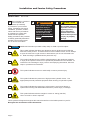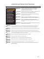
1
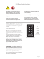
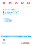
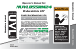
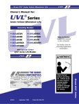
Owner Manual for: UVL601C UVL603C UVL603C24 Under-Vehicle Lift® Series 04 www.braunability.com/international ISO 9001:2008 631 West 11th Street, Winamac, IN 46996, USA Phone: +1 574 946 6153 Fax: +1 574 946 4670 37275 December 2011 Original Instructions Congratulations We at The Braun Corporation wish to express our fullest appreciation on your new purchase. With you in mind, our skilled craftsmen have designed and assembled the finest lift available. This manual provides safety precautions, installation instructions, and operating instructions. Braun UVL Series™ lifts are built for dependability and will provide years of pleasure and independence as long as the lift is properly maintained and operated by an instructed person. Sincerely, THE BRAUN CORPORATION Ralph W. Braun Chief Executive Officer Warranty Consult your local Braun dealer regarding warranty policy. www.braunlift.com/international The Braun Corporation 1-800-THE LIFT® BRAUNLIFT.COM® MODEL NUMBER Model No. XXXXXXXXXX SERIAL NUMBER Serial No. XX-XXXXX MFG DATE DatHRI0DQXIDFWXUH XX/XX/XXXX 6DPSOH6HULDO1R6HULHV1R,GHQWLÀFDWLRQ7DJ Serial No. Model No. OWNER'S WARRANTY REGISTRATION XXXXXXXXXX XX-XXXXX PURCHASED FROM OWNER DATE INSTALLED NAME ADDRESS CITY TELEPHONE STATE ZIP TO VALIDATE WARRANTY REGISTRATION CARDS MUST BE RETURNED TO THE BRAUN CORPORATION. Sample Warranty/Registration Card Contents Installation and Service Safety Precautions .......... 2 - 3 Lift Operation Safety .............................................. 4 - 6 6SHFLÀFDWLRQV Vehicle Physical Requirements ................................... 8 Lift Terminology ........................................................... 9 Lift Installation Locate Lift Mounting Holes .............................. 10 Secure Lift ................................................ 11 - 12 Electrical and Hydraulic ............................ 13 - 15 Switch Adjustment .................................... 16 - 17 Carriage Adjustment ........................................ 17 ,QVWDOOHU9HULÀFDWLRQ Lift Operation Safety .......................................... 20 - 22 Lift Operating Instructions .................................. 23 - 24 Manual Operating Instructions ........................... 25 - 26 Maintenance and Lubrication Schedule ............. 27 - 31 Declarations Declaration of Conformity - Machinery ..... 32 - 33 Declaration of Noise Emission ........................ 34 Declaration of Conformity - EMC ..................... 35 Document Cross Reference Service Manual 37274 Page 1 Installation and Service Safety Precautions Safety Symbols SAFETY FIRST! Know That.... The information contained in this manual and supplements (if included), is provided for your use and safety. Familiarity with proper installation, operation, maintenance and service procedures is necessary to ensure safe, trouble free lift operation. Safety precautions are provided to identify potentially hazardous situations and provide instruction on how to avoid them. A D NOTICE B WARNING This symbol indicates important safety information regarding a potentially hazardous situation that could result in serious bodily injury and/or property damage. C CAUTION This symbol indicates important information regarding how to avoid a hazardous situation that could result in minor personal injury or property damage. $GGLWLRQDOLQIRUPDWLRQSURYLGHGWRKHOSFODULI\RUGHWDLODVSHFLÀFVXEMHFW E This symbol indicates that there are dangerous energy levels present inside the HQFORVXUHRIWKLVSURGXFW7RUHGXFHWKHULVNRIÀUHRUHOHFWULFVKRFNGRQRWDWWHPSW to open the enclosure or gain access to areas where you are not instructed to do VR5HIHUVHUYLFLQJWRTXDOLÀHGVHUYLFHSHUVRQQHORQO\ F This symbol indicates that a condition where damage to the equipment resulting in injury to the operator could occur if operational procedures are not followed. To reduce the risk of damage or injury, refer to accompanying documents, follow all steps or procedures as instructed. G This symbol indicates an area to avoid bodily contact to prevent injury. 36514 H This symbol indicates the presence of high pressure hydraulic hoses. Use appropriate personal protective equipment when working on hydraulic system. I 7KLVV\PEROLQGLFDWHVWKHSUHVHQFHRIDÀUHKD]DUG$YRLGRSHQÁDPHVRU VSDUNVZKHQZRUNLQJZLWKÁDPPDEOHPDWHULDOVWRSUHYHQWLQMXU\RUGDPDJH J This symbol indicates a device weighs in excess of 150 kg (330 lbs). Use of a fork lift or hoist is required. These symbols will appear throughout this manual as well as on the labels posted on your lift. Recognize the seriousness of this information. Page 2 Installation and Service Safety Precautions Installation/Service Safety Precautions WARNING If installation, maintenance or repair procedures cannot be completed exactly as provided in this manual or if the instructions are not fully understood, contact The Braun Corporation immediately. Failure to do so may result in serious bodily injury and/ or property damage. WARNING Read this manual, supplement(s), and operating instructions decals before performing installation, operation, or service procedures. CAUTION 0LQLPXPFOHDUGRRURSHQLQJGLPHQVLRQVVSHFLÀHGLQ/LIW Dimensions per lift model must be provided. WARNING Use appropriate personal protective equipment when installing and servicing lift. WARNING Remove any obstructions within the lift mounting/ operating area prior to beginning installation procedures. WARNING Check for obstructions such as gas lines, wires, exhaust, etc. before drilling or cutting during installation procedures. WARNING Route all cables clear of exhaust system, other hot areas, moving parts, wet areas, etc. WARNING 5LVNRIHOHFWULFDOVKRFNRUÀUH8VHH[WUDFDUHZKHQPDNLQJHOHFWULFDOFRQQHFWLRQV Connect and secure as outlined in Installation Instructions and Wiring Diagrams. WARNING $GMXVWYHKLFOHÁRRUOHYHOSRVLWLRQLQJRIEULGJHSODWHEHIRUHRSHUDWLQJOLIWZLWKSDVVHQJHU WARNING Maintenance and repairs must be performed only by authorized service personnel. WARNING Perform maintenance and lubrication procedures exactly as outlined in the Maintenance and Lubrication Schedule contained in this manual. WARNING Disconnect the power cable at the battery prior to servicing. WARNING Never modify (alter) a Braun Corporation lift. WARNING Replacement parts must be Braun authorized replacements. WARNING Never install screws or fasteners (other than factory equipped). WARNING Whenever replacing a hydraulic cylinder or seals, lower platform fully. WARNING Failure to follow these safety precautions may result in serious bodily injury and/or property damage. Page 3 Lift Operation Safety Safety Symbols SAFETY FIRST! Know That.... The information contained in this manual and supplements (if included), is provided for your use and safety. Familiarity with proper installation, operation, maintenance and service procedures is necessary to ensure safe, trouble free lift operation. Safety precautions are provided to identify potentially hazardous situations and provide instruction on how to avoid them. A D NOTICE B WARNING This symbol indicates important safety information regarding a potentially hazardous situation that could result in serious bodily injury and/or property damage. C CAUTION This symbol indicates important information regarding how to avoid a hazardous situation that could result in minor personal injury or property damage. $GGLWLRQDOLQIRUPDWLRQSURYLGHGWRKHOSFODULI\RUGHWDLODVSHFLÀFVXEMHFW E This symbol indicates that there are dangerous energy levels present inside the HQFORVXUHRIWKLVSURGXFW7RUHGXFHWKHULVNRIÀUHRUHOHFWULFVKRFNGRQRWDWWHPSW to open the enclosure or gain access to areas where you are not instructed to do VR5HIHUVHUYLFLQJWRTXDOLÀHGVHUYLFHSHUVRQQHORQO\ F This symbol indicates that a condition where damage to the equipment resulting in injury to the operator could occur if operational procedures are not followed. To reduce the risk of damage or injury, refer to accompanying documents, follow all steps or procedures as instructed. G This symbol indicates an area to avoid bodily contact to prevent injury. 36514 H This symbol indicates the presence of high pressure hydraulic hoses. Use appropriate personal protective equipment when working on hydraulic system. I 7KLVV\PEROLQGLFDWHVWKHSUHVHQFHRIDÀUHKD]DUG$YRLGRSHQÁDPHVRU VSDUNVZKHQZRUNLQJZLWKÁDPPDEOHPDWHULDOVWRSUHYHQWLQMXU\RUGDPDJH J This symbol indicates a device weighs in excess of 150 kg (330 lbs). Use of a fork lift or hoist is required. These symbols will appear throughout this manual as well as on the labels posted on your lift. Recognize the seriousness of this information. Page 4 Lift Operation Safety Lift Operation Safety Precautions WARNING If the lift operating instructions, manual operating instructions and/or lift operation safety precautions are not fully understood, contact The Braun Corporation immediately. Failure to do so may result in serious bodily injury and/or property damage. WARNING Read manual and supplement(s) before operating lift. Read and become familiar with all safety precautions, operation notes and details, operating instructions and manual operating instructions before operating the lift. WARNING Load and unload on level surface only. WARNING Engage vehicle parking brake before operating lift. WARNING Provide adequate clearance outside the vehicle to accommodate the lift before opening lift door(s) or operating lift. WARNING Inspect lift before operation. Do not operate lift if you suspect lift damage, wear, or any abnormal condition. WARNING Do not use lift as a link bridge. WARNING Keep operator and bystanders clear of area in which the lift operates. WARNING Lift attendant must observe passenger at all times during lift operation. WARNING Ensure adequate lighting exists in the lift operating area. WARNING Whenever a wheelchair passenger (or standee) is on the platform, the: 3DVVHQJHUPXVWEHSRVLWLRQHGLQWKHFHQWHURIWKHSODWIRUPIDFLQJRXWZDUG :KHHOFKDLUEUDNHVPXVWEHORFNHG %ULGJHSODWHDQGUROOVWRSPXVWEHXSYHUWLFDO WARNING Wheelchair lift attendants should be instructed on any special needs and/or procedures required for safe transport of wheelchair passengers. WARNING /RDGDQGXQORDGFOHDURIYHKLFXODUWUDIÀF WARNING Do not attempt to load or unload a passenger in a wheelchair or other apparatus that GRHVQRWÀWRQWKHSODWIRUPDUHD WARNING The lift attendant shall not ride on the platform with the passenger. The lift is intended for use by a single passenger. WARNING Do not overload or abuse. The load rating applies to both the raising and lowering functions - continuous lifting capacity is 340 kg (750 lbs.). WARNING Use caution when operating this equipment out of doors during electrical storms or similar electrical phenomena. WARNING Use caution when operating this equipment in severe weather or environmental conditions (fog, rain, snow, ice, dust, etc.) WARNING Discontinue lift use immediately if any lift or vehicle interlock does not operate properly. WARNING Do not operate or board the lift if you or your lift operator are intoxicated. WARNING Do not raise front wheelchair wheels (pull wheelie) when loading (boarding) the platform. Page 5 Lift Operation Safety WARNING Open lift door(s) fully and secure before operating lift. WARNING Position and secure (buckle, engage, fasten, etc.) the wheelchair-equipped occupant seat belt (torso restraint) before loading onto the wheelchair lift platform. WARNING Lift attendants must ensure that lift occupants keep hands, arms and all other body parts within the lift occupant area and clear of moving parts. WARNING 3ODWIRUPPXVWEHSRVLWLRQHGDWÁRRUOHYHOEULGJLQJSRVLWLRQZKHQORDGLQJRU unloading in and out of vehicle. WARNING Do not use platform bridge plate or roll stops as a brake. Stop and brake wheelchair when loading onto the platform (manually stop and brake manual wheelchairs — stop powered wheelchairs with the wheelchair controls). WARNING Turn powered (electric) wheelchairs off when on lift platform. WARNING Press the DOWN switch until the entire platform rests on ground level (lowered fully) and the roll stops are fully unfolded (ramp position) before loading or unloading a passenger at ground level. WARNING Accidental activation of control switch(es) may cause unintended operation(s). WARNING After manually releasing platform, stow platform and push manual release T-handle in fully and move platform in and out to engage platform lock before driving vehicle. Failure to lock platform may result in unintended platform deployment. WARNING Insert manual release T-handle fully before manually lowering or raising platform and manually move platform in and out to engage platform lock. WARNING 0DLQWHQDQFHDQGOXEULFDWLRQSURFHGXUHVPXVWEHSHUIRUPHGDVVSHFLÀHGLQWKLV PDQXDOE\DXWKRUL]HGFHUWLÀHGVHUYLFHSHUVRQQHO WARNING Replace missing, worn or illegible decals. WARNING Never modify (alter) a Braun Corporation lift. WARNING Do not use accessory devices not authorized by The Braun Corporation. WARNING Do not remove any guards or covers WARNING Keep clear of any hydraulic leak. WARNING Failure to follow these safety precautions may result in serious bodily injury and/or property damage. Page 6 Specifications The lift must be installed, operated, and maintained as detailed in applicable manual. Any use of equipment other than instructed in this manual is prohibited. The UVL601C and UVL603C have completed 15,600 cycles with a 340kg (750 lb.) load and a static load test with a 1020 kg (2250 lb) load. Operating Temperature This equipment will operate in its intended ambient at a minimum between +5ºC and +40ºC. Relative Humidity This equipment will operate correctly within an environment at 50% RH, at 40ºC. Altitude This equipment will operate correctly up to 1000m above mean sea level. Sound Pressure Level The emission sound pressure level at the operator’s position is expected not to exceed 70 db(A). Transportation and Storage This equipment will withstand, or has been protected against, transportation and storage temperatures of -25ºC to +55ºC, and for short periods of up to +70ºC. The lift has been packaged to prevent damage from the effects of normal humidity, vibration, and shock. Power Requirements 12 VDC -- UVL601C and UVL603C 24 VDC -- UVL603C24 Lift Weight (Installed) UVL601C -- 155 kg (341 lbs) UVL603C and UVL603C24 -- 166 kg (365 lbs) Lifting Capacity Maximum 340 kg (750 lbs.) 60 mm 8 3 mm 4 14 1C -5 60 3 C 60 60 1C -7 3C - 8 62 m 12 mm m 63 mm Dimension from top of housing. WARN ING Push manuaT-hand and lly le lock out movein fully to Failurbefore engagplatfo and resulte to drivine rm deployin lock gplatfo in uninteplatfovehiclrm platfo ment. nded rm e. resultrm may Uninte platfo and/orin deploy seriou nded rm prope ment s may rty bodily damag injury Do not e. remo ve! 81823 = Center of Gravity Page 7 Vehicle Physical Requirements OEM (Van) Chassis Floor Requirements Lift must be secured with minimum of two all-thread mounting brackets per frame rail (minimum four mounting brackets securing lift). LE R HIC BE VE MEM SIS S A CH All-thread Mounting Brackets LE R HIC BE VE MEM SIS S A CH Continuous Load Rating: 340 kg. (750 lbs.) Figure A 40. 6 Ma 4 cm xim um Driveline “Full Suspension Travel” Clearance: Following installation, the installer must ensure vehicle drive shaft cannot contact lift. There must be a minimum 2.54 cm clearance between drive shaft (one piece or two) and lift. To ensure clearance, raise vehicle using a hoist capable of supporting chassis (allowing rear axle to relax to maximum extension before measuring clearance). The Braun Corporation does not recommend using axle limiting devices (may degrade vehicle safety). Split drive shafts may provide additional clearance in some applications. Following installation, installer must ensure acceptable clearance between lift and pavement. The Braun Corporation recommends minimum 12.7 cm clearance under normal driving conditions when loaded to maximum capacity. Aftermarket suspension kits can assist in maximizing ground clearance if properly utilized. In some cases, aftermarket exhaust accessories allow UVL to be mounted closer to vehicle frame, (increasing clearance). Increasing wheel and tire size may increase ground clearance, but may void vehicle warranty, negatively affect handling and render inaccurate odometer and speedometer reading. Drive Shaft Clearance: UVL FULL Suspension Travel Page 8 Minimum 2.54 cm Clearance There must be a minimum 2.54 cm clearance between drive shaft (one piece or two) and lift with van supported by chassis and rear axle fully relaxed (suspended). C h a s s i s L i f t Figure B Lift Terminology Lift Mounting Bracket Hand-Held Pendant Control Chain Drive Motor Hydraulic Cylinder Lift Housing Bridge Plate LIFT UP N LIFT DOW STOW LIFT R SE DOO CLO 81812 Ca rria ge Rolling Horizontal Arms Roll Stop Actuator WA RN ING Push manu T-han and ally dle lock out movein fully to Failurbefor engagplatfo and resulte to e drivine rm deplo in lock gplatfo in uninteplatfovehicrm platfoymen resultrm t. nded rm le. may and/o in deploUnint platfo seriouymenended rm r prope s t may rty bodily dama injury Do ge. not remo ve! Pump Module Platform Cable-activated Manual Release System 81823 Platform Torque Tube Lifting Arms Inboard Left Roll Stop Right Outboard The lift must be installed, operated, and maintained as detailed in this manual. Any use of equipment other than instructed in this manual is prohibited. Braun wheelchair lifts provide a method of boarding and exiting applicable motor vehicles. Braun wheelchair lifts accommodate wheelchair passengers, standees, and other mobility aid users. Page 9 Lift Installation Locate Lift Mounting Holes Figure C Locate All-Thread Mounting Brackets E ACR FRA OSS O cm 53 cm 53 All-Thread Mounting Brackets Engage Platform Manual Release System: The lift cable-activated platform manual release is disengaged during shipment to prevent potential drive chain stretch. Handle the lift with care. Engage manual release before attempting to install (raise, tilt or move) the lift. WARNING Engage manual release before attempting to install (raise, tilt or move) lift. Failure to do so may result in serious bodily injury and/or property damage. Page 10 R 90 /RFDWHEUDFNHWVDVVSHFLÀUHGLQ Figure C 4. Clamp the mounting brackets securely in place (all-thread studs must be vertical). O P E N IN G ME O 2. Transfer center point to the vehicle frame. Using a frontto-rear framing member as a guide, transfer the center point across chassis to opposite side front-to-rear framing member (must be 90° to door opening). ICL TER D 1. Locate center of door opening. IN ER ING T N N CE OPE OR DO CL CEN VEH WARN ING Push manuaT-hand and lly le lock out movein fully to before Failure engagplatforand result to driving e platfor m in deployin lock uninteplatfor vehiclm platfor ment. nded m e. result m may Uninte platfor and/orin deploy seriou nded m proper ment s may ty bodily damag injury Do not e. remo ve! 81823 cm 106 Lift Installation Secure Lift “Channel” Framing Member WARNING Check for obstructions such as gas lines, wires, exhaust, etc. before drilling or cutting. Failure to do so may result in serious bodily injury and/or property damage. Hex Nut Lock Washer Flat Washer All-Thread Bracket 3/8-16 x 1-1/2" Hex Bolt Figure D Attach Mounting Brackets to Vehicle Frame Mounting bolts must be routed horizontally through framing members as shown in Figures D, E and F. Carefully drill 25/64" (.390") diameter mounting holes at the center of the oval mounting slots. Channel Frame Applications: Secure mounting bolts as VSHFLÀHGLQ)LJXUH' “Box” Framing Member All-Thread Bracket Lock Washer 3/8-16 x 1-1/2" Hex Bolt Box Frame Spacers: Position tubing spacers as shown at right to prevent collapsing the box frame. Cut spacer tubing to length (equal to thickness of box frame). Insert spacer through 5/8” (.625) diameter hole. Secure mounting EROWVDVVSHFLÀHGLQ)LJXUHV( and F. Shipping Block Removal: Wood blocks are placed in the lift housing to prevent lift damage during shipment. Remove shipping blocks from platform and carriage before running (activating) lift. Refer to Shipping Block Removal Instruction 28942. Hex Flat Nut Washer Figure E Flat Washer 3/8-16 Hex Bolt All-Thread Bracket Spacer 25/64" Diameter Hole Box Framing Member Assembled Figure F Flat Washer Spacer Flat Washer “Box” Framing Member 5/8" Diameter Hole Hex Nut Lock Washer Spacer Tubing Length: Equal to thickness of box frame. Page 11 Lift Installation Secure Lift Figure G LE R HIC BE VE MEM IS S AS CH LE R HIC BE VE MEM IS SS A CH Lift Housing LE R HIC BE VE MEM IS SS A CH Lift Clamp All-Thread Stud Jam Nuts Flat Washer Lift Clamp Figure I Jam Nuts Lift Housing Jam Nuts Flat Washer Align mounting clamps with all-thread studs. Figure H WAR NING Lift Clamp Push manual T-hand and ly le lock out movein fully to before Failure platform engage and result to driving platform in deploym in lock vehicle platform platform uninten result ent. . ded may Unintenplatform and/orin deploym serious propert ent ded may bodily y damage Do injury not . remov e! 81823 Flat Washer Jam Nuts Position and secure lift. Thread two 3/4" hex jam nuts fully onto each mounting bracket all-thread stud. 3ODFHRQHODUJHGLDPHWHUÁDWZDVKHU onto each all-thread stud (use tape to hold in place). See Figures G and H. Carefully raise lift into position as high as SRVVLEOH3ODFHRQHODUJHGLDPHWHUÁDWZDVKHU onto each mounting bracket all-thread stud. Thread two 3/4" hex jam nuts fully onto each all-thread stud (up against lift mounting clamp). Carefully position lift under vehicle (aligned with mounting brackets). Position (slide) the four lift mounting clamps along the sides of the lift housing until aligned with mounting bracket allthread studs. See Figure G. Shift lift and mounting brackets left-to-right as needed (lift must be centered in door opening). Tighten the 3/8" bolts securing mounting EUDFNHWVWRWKHIUDPH7RUTXH6SHFLÀFDWLRQV 160 Nm. Height Adjustment dimensions A, B, C and D must be equal (within 3 mm). See Figure J. In-Out Positioning Position the lift to achieve a 38 mm overlap between the deployed bridge plate DQGWKHYHKLFOHÁRRU Tighten upper set of 3/4" hex jam nuts ZLWKÁDWZDVKHU down to the lift mounting clamps. Tighten jam nuts. 7RUTXH6SHFLÀFDtions: 136 to 163 Nm. B LE R HIC BE VE MEM SIS AS H C C LE R HIC BE VE MEM SIS AS H C A D 40. 6 Ma cm xim um Page 12 Dimensions A, B, C, and D must be equal (within 3 mm). Figure J Lift Installation Electrical and Hydraulic 5/16" Lag Bolts (typical - 4) Mi 4.4 n. 5c m to Wa ll Mo u Pu nt Ve mp rtic al 1/4-20 x 3/8" Hex Screws Through-Floor Cable and Hose Grommet 76 mm (3") Diameter Mounting Hole Lock Washer Reinforcement “L” Bracket Cable-activated Manual Release (from lift) Pump Mounting Bracket 22 mm (7/8") Diameter Mounting Hole Note: Seal the ÁRRUFDEOHDQG hose grommet following installation procedures ÀOOZLWKVLOLFRQH Figure K Pump Module Mounting Cable-activated Manual Release: Mount reinforcement “L” bracket to pump mounting bracket as shown in Figure K. 6HFXUHSXPSPRXQWLQJEUDFNHWWRÁRRUXVLQJ four 5/16" lag bolts. The T-handle must be mounted inside the vehicle. The cable must operate freely (no kinks or bends). The warning tag must remain attached to the handle. Remove handle for installation. Check under vehicle for obstructions before GULOOLQJFXWWLQJKROHVRULQVWDOOLQJÁRRU mounting hardware. Note: Locate and drill pump module PRXQWLQJKROHVÁRRUJURPPHWKROHDQG manual release hole before mounting pump GLDPHWHUVVSHFLÀHG Page 13 Lift Installation Electrical and Hydraulic Note: Remove plug from vent tube. Hydraulic Hose L To Connect red positive (+) power cable here (from circuit protection device). ift t an d en dP n Ha g rin i W ift esses L n in Ma Har Figure N Hydraulics: Interlock Instructions EU Remove the plug from 1/4" diameter clear vent tube. See Figure N. The lift shall be installed in such way that the lift can not be operational unless the vehicle is immobilized. Install a microswitch to the hand brake that provides signal when the hand brake is pulled (Installer provided). When installed, verify that the lift is not operational unless the hand brake is pulled. Route hydraulic hose from pump through ÁRRUJURPPHWWRTXLFNGLVFRQQHFWÀWWLQJ at lift. Connect hose. Page 14 Lift Installation Electrical and Hydraulic OEM (+) Cable OEM (-) Cable Lead Cable Rd - 4 Gauge (21.1mm2) Vehicle Battery Positive Cable: B at . Ne g. Vehicle Battery A ux . T LI O FT Install in-line circuit protection device as shown in Figure L (use in-line circuit protection device kit provided by The Braun Corporation, or CE equivalent). Attach power cable and lead cable as shown. Connect power cable to pump solenoid as shown in Figure N. Po s. Circuit Protection Device Power Cable Rd - 4 Gauge (21.1mm2) Figure L Ground Cable to Chassis 4 Gauge (21.1mm2) (not supplied) Lift Power Switch: A lift on/off power switch must be installed. Use switch kit 36678KS* or CE equivalent. E-Stop Switch: An E-Stop switch must be installed at the operator control station. Use E-Stop switch kit 36679KS* or CE equivalent. 9/32” Diameter Pilot Hole sis as Ch 5/16-18 x 3/4” Thread Cutting Screw * Available from The Braun Corporation 5/16” External Tooth Star Washer Pump Ground Cable: Route the pump mounted ground cable WKURXJKWKHÁRRUJURPPHWDQGFRQQHFWLW to a vehicle framing member as shown in Figure M. Vehicle Battery Ground Cable: A 4 gauge (21.1 mm2) ground cable must be connected from vehicle battery negative post to the same vehicle framing member the pump ground cable is attached to. See Figures L and M. Figure M Ground Cable Corrosion: When mounting ground cables, remove undercoating, dirt, rust, etc. from framing member around mounting holes. Apply protective coating to mounting holes to prevent corrosion. Failure to do so will void warranty of certain electrical components. Page 15 Lift Installation Switch Adjustment Lift Out Limit Switch 73950A Lift Out Cam 73774 Full Out Limit Switch 73950A Full Out Cam 73775 Below Stow Limit Switch 73950A Floor Level Limit Switch 73950A Floor Level Cam 73712 36514 Below Stow Cam 73712 Roll Stop Limit Switch 73950A LIFT UP LIFT DOWN STOW LIFT DOOR CLOSE 81812 WARN ING Push manual T-handl and ly e lock out movein fully to before Failure platform engage and result to driving platform in deploym in lock vehicle platform platform uninten result ent. . ded may Unintenplatform and/orin deploym serious propert ent ded may bodily y damage Do injury not . remov e! 81823 Pressure Switch 87052 Pressure Switch 73960A Switch LED Diagnostics Lift Out Switch: The Lift Out Switch stops inward travel of the carriage/platform during Stow function (activated by the housing-mounted Lift Out Cam). Move cam in to increase inward travel. Move cam out to decrease inward travel. Diagnostic LED “LIFT OUT” will be illuminated when the switch is not contacting the cam. Full Out Switch: The Full Out Switch stops outward travel of the carriage/platform during Deploy (Up/Down) functions (activated by the housingmounted Full Out Cam). Move cam in to decrease outward travel. Move cam out to increase outward travel. Carriage rollers must be inside housing a minimum 13 mm (1/2"). The platform will not raise or lower until this switch is activated. Diagnostic LED “FULL OUT” will be illuminated when the switch is contacting the cam. Page 16 Floor Level Switch: Diagnostic LED “FL LVL” will be illuminated when the switch is contacting the cam. Adjustment details below. Below Stow (Stow Start) Switch: The Below Stow Switch controls the height of the carriage/ platform before it moves inward during the Stow function (activated by the torque tube-mounted Stow Start Cam). Rotate the cam in to decrease platform height. Rotate the cam out to increase platform height. Adjust cam so bottom of platform LVÁXVKZLWKWKHKRUL]RQWDODUPVZKHQVZLWFKLV activated. Diagnostic LED “BELOW” will be illuminated when platform is at stow start height or below. Lift Installation Switch Adjustment Floor Level Switch Adjustment Floor Level Cam Floor Level Switch The Floor Level switch stops upward travel of the platform during the Up function (activated by the torque tube-mounted Floor Level cam). Position the bottom of the lift platform 38 mm (1 DERYHÁRRUOHYHOXVLQJWKHPDQXDORSHUDtion system. Loosen the clamp securing the torque tube-mounted Floor Level cam. Rotate the cam until the Floor Level switch is activated (cam depresses switch). Torque Tube Cam Depressing Switch 1RWH&KHFNWKHÁRRUOHYHOSRVLWLRQRIWKHSODWform and the bridge plate after powering the pump. Hydraulic pressure may affect platform height slightly. Fine tuning adjustment (tweaking) of the Floor Level switch may be required. Carriage Adjustments 36514 Carriage Ride Height Adjustment The carriage horizontal arms move (roll) in and out of the housing tracks on roller bearings. Following installation or extensive lift operation, clearance between horizontal arms and tracks may diminish. The eccentric shaft mounting plate allows height adjustment. Remove eccentric plate mounting screw. Using screwdriver or small rod, rotate the shaft clockwise to increase carriage height. Rotate the shaft counterclockwise to decrease carriage height. Reinstall mounting screw in nearest retainer hole. Adjust left and right side eccentric shafts (screw positions may vary from side to side). Adjust height such that horizontal arms do not contact top or bottom of tracks (align center). 1. Unlock and pull the manual release cable and lock in released position. 2. Manually extend platform carriage 2/3 full out. 3. Remove adjustment bolt (tensioner) access cover. 4. Use deep well socket (long key sleeve) to loosen outside jam nut. Tighten inside jam nut to eliminate visible chain sag but do not overtighten. 5. Lock jam nuts together. Unlock and push the manual cable in fully. Lock release cable. Move the platform in and out until platform chain release assembly engages chain. Access Cover Jam Nuts Tensioner Drive Chain Adjustment In event the drive chain sags 13 mm (1/2”) or more, adjust tension as detailed. Tighten to eliminate visible sag but do not overtighten. See illustration at right. WA RN ING Pu sh ma T-h an nuallyandle d loc out mo in ful to ve Fa k befor en pla ly an ilu ga res re to e dri ge tform d de ult in loc vingplatfo in plo k rm pla ym unint platfovehicle restform ent. ende rm . an ult in deploUnintd pla may d/o ser ym en tfo r pro iou en de rm pe s bo t mad rty dil y da y inj Do ma ge ury not . rem ove! 8182 3 Manual Release Cable Page 17 Verification by the Installer Compatibility between the lift and the vehicle 7KHLQVWDOOHUVKDOOFRQÀUPWKHFRPSDWLELOLW\EHWZHHQWKHOLIWDQGWKHYHKLFOH Static Test Deformation 7KHXQODGHQSODWIRUPLVSRVLWLRQHGPLGZD\EHWZHHQJURXQGOHYHODQGYHKLFOHÁRRUOHYHODQG PHDVXUHPHQWVDUHWDNHQRIWKHKHLJKWRIWKHSODWIRUPDQGLWVDQJXODUDWWLWXGHUHODWLYHWRWKHYHKLFOHÁRRU A load of 425k is applied to the platform and subsequently removed. By repeating measurements of the height and attitude of the platform, verify that no permanent deformation has occurred in any part of the lift or its attachment to the vehicle which could affect the function of the lift. Drift $ORDGRINJLVDSSOLHGWRWKHSODWIRUPSRVLWLRQHGDWÁRRUOHYHO0HDVXUHPHQWVDUHWDNHQRIWKH KHLJKWRIWKHSODWIRUPDQGLWVDQJXODUDWWLWXGHUHODWLYHWRWKHYHKLFOHÁRRU7KHVHPHDVXUHPHQWVDUH repeated after a 15 minute test period. Verify that the vertical drift of the platform between the two measurements has not exceeded 15mm. Verify that the angular drift of the platform between the two measurements has not exceeded 2º. If lift does drift: 1. Deploy lift to ground level. 2. Press circuit board manual override buttons L-UP and L-DN for 20 seconds. 3. Open manual down valve 1 turn and press “UP” on hand pendant for 20 seconds. Close valve. Test to Verify that the Lift Cannot Lift Excessive Load A load of 425kg is applied to the platform, positioned at ground level. Actuate the “UP” control and verify that the platform does not lift (tilt is permissible). 1. Lower platform to the ground. 2. Place 425kg at center of platform. 3. Press up switch and verify platform does not lift (tilt is permissible). 4. If platform does not lift, proceed to Dynamic Test. If platform does lift, proceed to step 5, pump relief valve adjustment is necessary. 5. Access relief valve through circuit board mounting plate access hole. Loosen 9/16" hex nut on the relief valve adjustment screw (do not remove hex nut). 6. Turn adjustment screw counterclockwise1/8 turn. 7. Press up switch and verify platform does not lift (tilt is permissible). 8. If platform does not lift, tighten 9/16" hex nut (do not turn relief valve adjustment screw while tightening hex nut). If platform does lift, repeat steps 6 through 8 Page 18 Verification by the Installer Dynamic Test With 340kg applied to the platform, verify that the lift is able to operate throughout its full range of normal lifting and lowering. 1. Lower platform to the ground. 2. Place 340kg at center of platform. 3. Press up switch and verify that the lift is able to operate throughout its full range of normal lifting and lowering movements. 4. If platform is able to operate throughout its full range of normal lifting and lowering movements, no adjustment is necessary. If platform does not lift, proceed to step 5, pump relief valve adjustment is necessary. 5. Access relief valve through circuit board mounting plate access hole. Loosen 9/16" hex nut on the relief valve adjustment screw (do not remove hex nut). 6. Turn adjustment screw clockwise 1/8 turn. 7. Press up switch and verify lift is able to operate throughout its full range of normal lifting and lowering movement. 8. If lift does not operate throughout its full range, repeat steps 6 through 8. If lift does operate throughout its full range, tighten 9/16" hex nut (do not turn relief valve adjustment screw while tightening hex nut). Test of Operations and Safety Functions $OOIXQFWLRQVRIWKHOLIWDQGRSHUDWLRQVRIDOOVDIHW\GHYLFHVDUHYHULÀHGDIWHUWKHVWDWLFDQGG\QDPLFWHVWV have been completed. These tests do not apply to pipe break valves nor non-resettable safety devices such as electrical fuses (These items are the subject of a manufacturer’s type test). Relief Valve Adjustment Screw 9/16" Hex Nut Page 19 Lift Operation Safety Safety Symbols SAFETY FIRST! Know That.... The information contained in this manual and supplements (if included), is provided for your use and safety. Familiarity with proper installation, operation, maintenance and service procedures is necessary to ensure safe, trouble free lift operation. Safety precautions are provided to identify potentially hazardous situations and provide instruction on how to avoid them. A D NOTICE B WARNING This symbol indicates important safety information regarding a potentially hazardous situation that could result in serious bodily injury and/or property damage. C CAUTION This symbol indicates important information regarding how to avoid a hazardous situation that could result in minor personal injury or property damage. $GGLWLRQDOLQIRUPDWLRQSURYLGHGWRKHOSFODULI\RUGHWDLODVSHFLÀFVXEMHFW E This symbol indicates that there are dangerous energy levels present inside the HQFORVXUHRIWKLVSURGXFW7RUHGXFHWKHULVNRIÀUHRUHOHFWULFVKRFNGRQRWDWWHPSW to open the enclosure or gain access to areas where you are not instructed to do VR5HIHUVHUYLFLQJWRTXDOLÀHGVHUYLFHSHUVRQQHORQO\ F This symbol indicates that a condition where damage to the equipment resulting in injury to the operator could occur if operational procedures are not followed. To reduce the risk of damage or injury, refer to accompanying documents, follow all steps or procedures as instructed. G This symbol indicates an area to avoid bodily contact to prevent injury. 36514 H This symbol indicates the presence of high pressure hydraulic hoses. Use appropriate personal protective equipment when working on hydraulic system. I 7KLVV\PEROLQGLFDWHVWKHSUHVHQFHRIDÀUHKD]DUG$YRLGRSHQÁDPHVRU VSDUNVZKHQZRUNLQJZLWKÁDPPDEOHPDWHULDOVWRSUHYHQWLQMXU\RUGDPDJH J This symbol indicates a device weighs in excess of 150 kg (330 lbs). Use of a fork lift or hoist is required. These symbols will appear throughout this manual as well as on the labels posted on your lift. Recognize the seriousness of this information. Page 20 Lift Operation Safety Lift Operation Safety Precautions WARNING If the lift operating instructions, manual operating instructions and/or lift operation safety precautions are not fully understood, contact The Braun Corporation immediately. Failure to do so may result in serious bodily injury and/or property damage. WARNING Read manual and supplement(s) before operating lift. Read and become familiar with all safety precautions, operation notes and details, operating instructions and manual operating instructions before operating the lift. WARNING Load and unload on level surface only. WARNING Engage vehicle parking brake before operating lift. WARNING Provide adequate clearance outside the vehicle to accommodate the lift before opening lift door(s) or operating lift. WARNING Inspect lift before operation. Do not operate lift if you suspect lift damage, wear, or any abnormal condition. WARNING Do not use lift as a link bridge. WARNING Keep operator and bystanders clear of area in which the lift operates. WARNING Lift attendant must observe passenger at all times during lift operation. WARNING Ensure adequate lighting exists in the lift operating area. WARNING Whenever a wheelchair passenger (or standee) is on the platform, the: 3DVVHQJHUPXVWEHSRVLWLRQHGLQWKHFHQWHURIWKHSODWIRUPIDFLQJRXWZDUG :KHHOFKDLUEUDNHVPXVWEHORFNHG %ULGJHSODWHDQGUROOVWRSPXVWEHXSYHUWLFDO WARNING Wheelchair lift attendants should be instructed on any special needs and/or procedures required for safe transport of wheelchair passengers. WARNING /RDGDQGXQORDGFOHDURIYHKLFXODUWUDIÀF WARNING Do not attempt to load or unload a passenger in a wheelchair or other apparatus that GRHVQRWÀWRQWKHSODWIRUPDUHD WARNING The lift attendant shall not ride on the platform with the passenger. The lift is intended for use by a single passenger. WARNING Do not overload or abuse. The load rating applies to both the raising and lowering functions - continuous lifting capacity is 340 kg (750 lbs.). WARNING Use caution when operating this equipment out of doors during electrical storms or similar electrical phenomena. WARNING Use caution when operating this equipment in severe weather or environmental conditions (fog, rain, snow, ice, dust, etc.) WARNING Discontinue lift use immediately if any lift or vehicle interlock does not operate properly. WARNING Do not operate or board the lift if you or your lift operator are intoxicated. WARNING Do not raise front wheelchair wheels (pull wheelie) when loading (boarding) the platform. Page 21 Lift Operation Safety WARNING Open lift door(s) fully and secure before operating lift. WARNING Position and secure (buckle, engage, fasten, etc.) the wheelchair-equipped occupant seat belt (torso restraint) before loading onto the wheelchair lift platform. WARNING Lift attendants must ensure that lift occupants keep hands, arms and all other body parts within the lift occupant area and clear of moving parts. WARNING 3ODWIRUPPXVWEHSRVLWLRQHGDWÁRRUOHYHOEULGJLQJSRVLWLRQZKHQORDGLQJRU unloading in and out of vehicle. WARNING Do not use platform bridge plate or roll stops as a brake. Stop and brake wheelchair when loading onto the platform (manually stop and brake manual wheelchairs — stop powered wheelchairs with the wheelchair controls). WARNING Turn powered (electric) wheelchairs off when on lift platform. WARNING Press the DOWN switch until the entire platform rests on ground level (lowered fully) and the roll stops are fully unfolded (ramp position) before loading or unloading a passenger at ground level. WARNING Accidental activation of control switch(es) may cause unintended operation(s). WARNING After manually releasing platform, stow platform and push manual release T-handle in fully and move platform in and out to engage platform lock before driving vehicle. Failure to lock platform may result in unintended platform deployment. WARNING Insert manual release T-handle fully before manually lowering or raising platform and manually move platform in and out to engage platform lock. WARNING 0DLQWHQDQFHDQGOXEULFDWLRQSURFHGXUHVPXVWEHSHUIRUPHGDVVSHFLÀHGLQWKLV PDQXDOE\DXWKRUL]HGFHUWLÀHGVHUYLFHSHUVRQQHO WARNING Replace missing, worn or illegible decals. WARNING Never modify (alter) a Braun Corporation lift. WARNING Do not use accessory devices not authorized by The Braun Corporation. WARNING Do not remove any guards or covers WARNING Keep clear of any hydraulic leak. WARNING Failure to follow these safety precautions may result in serious bodily injury and/or property damage. Page 22 Lift Operating Instructions 36514 Before lift operation, park the vehicle on a OHYHOVXUIDFHDZD\IURPWUDIÀF3ODFHWKH vehicle transmission in “Park” and engage the parking brake. Vehicle engine must be running. Lift Operating Instructions address operation of the lift only. Vehicle Doors and Vehicle Interlocks: Transit vehicle lift doors and interlocks vary. Procedures to operate them vary also. Lift Lift Power ON/OFF Switch: This switch must be in the ON position in order to activate the lift. The Power Indicator Light illuminates to signal power to the lift. Control Switch Functions: UP: From the stowed position, the UP function extends the platform fully (platform moves out). 7KHSODWIRUPWKHQUDLVHVWRÁRRUOHYHOSRVLWLRQDQG stops. From ground level, the UP function will raise (rotate) the roll stop to the vertical position. The SODWIRUPWKHQUDLVHVWRÁRRUOHYHOSRVLWLRQ DOWN: The DOWN function lowers the platform to ground level and then unfolds (lowers) the roll stop to the ramp (horizontal) position. From the stowed position, the lift will extend and then lower when the DOWN switch is pressed. operators (attendants) must become familiar with the vehicle lift access door system and vehicle interlock(s). Manual Door(s): Open manual doors fully and secure in full open position before operating the lift. Do not operate the lift if you suspect lift damage, wear, or any abnormal condition. Refer to the Manual Operating Instructions to manually operate lift. LIFT UP UP LIFT DOWN DOWN STOW LIFT STOW DOOR CLOSE (non-functional) DOOR CLOSE 81812 Hand-held Pendant Control STOW: The STOW function raises or lowers the platform to stow level and then moves the platform inward to the stow position (platform retracts). DOOR CLOSE: If your vehicle is equipped with optional automatic door operators, the doors will open when the UP or DOWN switch is pressed. The automatic door operators will close when the DOOR CLOSE switch is pressed (only if the lift platform is in the fully stowed position). Note: If any functions do not occur as described, discontinue lift use immediately. Page 23 Lift Operating Instructions Lift Operating Instructions OPEN DOOR(S) AND SECURE Power Door Operator(s): Proceed to “TO DEPLOY PLATFORM.” Manual Door(s): Manually open door(s) fully and secure. TO LOAD PASSENGER: 1. Load passenger onto platform and lock wheelchair brakes. 2. Press UP switch to fold roll stop up fully (vertical), raise the SODWIRUPWRÁRRUOHYHODQGXQIROG EULGJHSODWHWRÁRRUOHYHO5Hlease switch. 3. Unlock wheelchair brakes and unload passenger from platform. TO DEPLOY PLATFORM: TO STOW PLATFORM: Stand clear and press the UP switch until the platform stops (extends fully and UDLVHVWRÁRRUOHYHODQGLQERDUGORFDWRU XQIROGVWRÁRRUOHYHO5HOHDVHVZLWFK Press STOW switch until platform stops (lowers to stow level and retracts fully). Release switch. TO UNLOAD PASSENGER: CLOSE DOOR(S) 1. Load passenger onto platform and lock wheelchair brakes. 2. Press DOWN switch until the entire platform reaches ground level and the roll stop unfolds fully (ramp position). Release switch. Power Door Operator(s): Press the DOOR switch until the door(s) are fully closed. Release switch. Manual Door(s): 3. Unlock wheelchair brakes and unload passenger from platform. Page 24 Manually close door(s) fully. Manual Operating Instructions 36514 T-Handle OPEN OSE CL WA RN ING OPEN Pu sh man Tha an ually ndle d lock out mov in fu Fa befoto en e platlly an ilu ga resu re tore dr ge form d de lt in lockivingplatfo in pl plat oym unin plat vehi rm te form cle. resuform ent. nded an lt in depl Unint platmay d/or se oy en fo propriousmen ded rm erty bo t may da dily in Do mag ju no e. ry t re mo ve! Hand Pump VALVE 818 Pump Handle 23 Pump Module CLOSE The T-handle releases and engages the platform carriage assembly to allow the platform to be manually extended and retracted. The hand pump is used to manually lower and raise the platform. Cable-Activated Platform Manual Release System A cable-activated manual release system engages the platform carriage assembly drive chain. Disengaging the drive chain allows the platform to be manually extended (out) or retracted (in). A T-handle is provided for activation of the manual release. After manually moving the platform in or out, the manual release must be positively re-engaged to lock the platform. Turn the T-handle and push the T-handle in fully. Grasp the roll stop and move the platform in and out until the platform locks. You will feel the release mechanism engage the drive chain. Ensure the platform is locked before driving lift vehicle. Failure to lock the platform carriage assembly will allow the platform to roll in or out of housing unhindered during vehicle movement. Notice: Push the lift platform fully into the lift housing before resuming powered operation. WARNING Push T-handle in fully and manually move platform in and out to engage platform lock before driving vehicle. Failure to lock platform may result in unintended platform deployment. Unintended platform deployment may result in serious bodily injury and/or property damage. Page 25 Manual Operating Instructions Note: Bridge plate automatically functions during manual operations. OUT (TO EXTEND PLATFORM): Pull T-Handle. Turn T-Handle to lock platform in released position. Pull platform out. Turn T-Handle. Push T-Handle in. Grasp roll stop and attempt to move platform in and out until the platform locks (feel release mechanism engage). Pu sh man Tha an ually ndle d lock out mov in fu Fa befoto en e platlly an ilu ga resu re tore dr ge form d de lt in lockivingplatfo in pl plat oym unin plat vehi rm te form cle. resuform ent. nded an lt in depl Unint platmay d/or se oy en fo propriousmen ded rm erty bo t may da dily in Do mag ju no e. ry t re mo ve! 818 23 VALVE OPEN OSE CL 1. 2. 3. 4. 5. 6. WA RN ING DOWN (TO LOWER PLATFORM): OPEN Using hand pump handle, open hand pump valve (turn counterclockwise). Open 1/2 turn only. CLOSE DOWN (TO UNFOLD ROLL STOP): 1. Remove hairpin cotter from detent pin. 2. Remove detent pin. 3. Unfold (rotate) barrier down. Ac Ha irp Co in tter tua tor B A R R IE R O U TE R 1. Fold (rotate) roll stop up. 2. Insert detent pin. 3. Insert hairpin cotter in detent pin. PL UP (TO FOLD ROLL STOP): AT F O R M t ten De n Pi VALVE OPEN Using hand pump handle: 1. Close hand pump valve (turn clockwise). 2. Insert handle in pump and stroke. OSE CL UP (TO RAISE PLATFORM): Note: Close valve before operating electric pump. IN (TO STOW PLATFORM): 1. Raise or lower platform to stow level (follow UP or DOWN procedures). 2. Pull T-Handle. 3. Turn T-Handle to lock platform in released position. 4. Push platform in. 5. Turn T-Handle. 6. Push T-Handle in. 7. Grasp roll stop and attempt to move platform in and out until the platform locks (feel release mechanism engage). WA RN ING Pu sh man Tha an ually ndle d lock out mov in fu Fa befoto en e platlly an ilu ga resu re tore dr ge form d de lt in lockivingplatfo in pl plat oym unin plat vehi rm te form cle. resuform ent. nded an lt in depl Unint platmay d/or se oy en fo propriousmen ded rm erty bo t may da dily in Do mag ju no e. ry t re mo ve! Page 26 818 23 Maintenance and Lubrication 36514 Proper maintenance is necessary to ensure safe, trouble free lift operation. Inspecting the lift for any wear, damage or other abnormal conditions should be a part of the transit agency daily service program. Simple inspections can detect potential problems. 3DUNYHKLFOHRQDOHYHOVXUIDFHFOHDURIWUDIÀFDQG bystanders. Place vehicle transmission in “Park” and engage parking brake. Deploy lift to ground level. Provide adequate work space around fullyGHSOR\HGOLIW3HUIRUPVSHFLÀHGPDLQWHQDQFHDQG lubrication procedures (position lift as required). Pump Module: When cleaning the exterior of WKHSXPSPRGXOHÀUVWGLVFRQQHFWWKHXQLWIURP its power source. Do not use liquid cleaners, aerosols, abrasive pads, scouring powders or solvents, such as benzine or alcohol. Use a soft cloth lightly moistened with a mild detergent solution. Ensure the surface cleaned is fully dry before reconnecting power. Other Components: Clean components and the surrounding area before applying lubricants. Clean only with mild detergent and water. Do not clean with solvents. Allow the lift to dry thoroughly DQGDSSO\OXEULFDQWVDVVSHFLÀHGDIWHUHYHU\ cleaning. LPS2 General Purpose Penetrating Oil is recommended where Light Oil is called out. Use of improper lubricants can attract dirt or other contaminants which could result in wear or damage to components. Platform components exposed to contaminants when lowered to the ground may require extra attention. WARNING Maintenance and lubrication procedures must be performed as VSHFLÀHGE\DQ authorized service technician. Failure to do so may result in serious bodily injury and/or property damage. Perform maintenance and lubrication procedures at the scheduled intervals according to the number of cycles. When servicing the lift at the recommended intervals, inspection and OXEULFDWLRQSURFHGXUHVVSHFLÀHGLQWKHSUHYLRXV sections should be repeated. These intervals are a general guideline for scheduling maintenance procedures and will vary according to lift use and conditions. Lifts exposed to severe conditions (weather, environment, contamination, heavy usage, etc.) may require inspection and maintenance procedures to be performed PRUHRIWHQWKDQVSHFLÀHG Records of maintenance and service procedures should be maintained. Discontinue lift use if maintenance and lubrication procedures are not properly performed, or if there is any sign of wear, damage or improper operation. Contact your sales representative. Page 27 Maintenance and Lubrication Schedule Lubrication Diagram Drive Chain Release Latch SG Drive Chain and Rollers LO Hydraulic Cylinder Pivot Points LO Carriage Rollers (bearings) LO Torque Tube Pivot Points LO Eccentric Shaft Rollers (bearings) LO Torque Tube Pivot Points LO Lifting Arm Pivot Points and Rollers (bearings) LO Rolling Horizontal Carriage Tube Slot Area DE Carriage Rollers (bearings) LO Roll Stop Detent Pin LO WA RN ING Push manu T-han and ally dle lock out movein fully to Failubefor enga platfo and resulre to e drivin ge rm deplot in lock gplatfo in unint platfovehicrm platfoymen resul rm t. ende rm le. may and/ot in deploUnin d platfo tende serio ymen r prop rm us t d may erty bodil dama y injur Do ge. y not rem ove ! Platform Cable-activated Manual Release System 81823 Bridge Plate Latch LO Lifting Arm Pivot Points and Rollers (bearings) LO Bridge Plate Linkage Pivot Points LO Bridge plate Hinge Pivot Points LO Roll Stop and Lower Closure Pivot Points LO See the Maintenance/Lubrication Schedule for recommended applications per number of cycles. Lubricant LO - Light Oil DE - Door-Ease SG - Synthetic Grease Page 28 Type Light Penetrating Oil (30 weight or equivalent Stainless Stick Style (tube) Synthetic Grease (Multipurpose) 6SHFLÀHGUHFRPPHQGHG$YDLODEOH Lubricant Amount %UDXQ Part No. LPS2, General Purpose Penetrating Oil 16 oz. Aerosol Can 15807 Door-Ease Stick (tube) 1.68 oz. 15806 Mobiltemp SHC32 12.5 oz. Tube 28598 Maintenance and Lubrication Schedule 750 Cycles Roll stop and lower closure pivot points (2) Apply Light Oil - See Lubrication Diagram Roll stop detent pin pivot points (2) Apply Light Oil - See Lubrication Diagram Bridge Plate hinge pivot points Apply Light Oil - See Lubrication Diagram Bridge plate linkage pivot points Apply Light Oil - See Lubrication Diagram Lifting arm pivot points and rollers (bearings) Apply Light Oil - See Lubrication Diagram Inspect roll stop and lower closure for proper operation Correct or replace damaged parts. Inspect roll stop seal and lower closure gasket Resecure, replace or correct as needed Inspect roll stop detent pin hairpin cotter Ensure hairpin cotter is present and can be removed and inserted easily. Resecure, replace or correct as needed. Inspect lift for wear, damage or any abnormal condition Correct as needed. Inspect lift for rattles Correct as needed. Check drive chain tension. Pull out and lock manual release cable. Adjust chain tension as needed. See Drive Chain Adjustment. Inspect bridge plate and linkage for: 3URSHURSHUDWLRQ 3RVLWLYHVHFXUHPHQW :HDURUGDPDJH 3URSHUDGMXVWPHQW Resecure, replace or correct as needed. See Floor Level Switch and bridge plate Adjustment Instructions in Service Manual. Check carriage ride height in housing Adjust as needed. See Carriage Ride Height Adjustment. Check stow height/lifting arm alignment Lifting arms should be horizontal, aligned with each other and aligned with carriage. Adjust as needed. See Switch Adjustment (Stow Switch) in Service Manual. Inspect wiring harnesses for securement, wear or other damage Resecure, replace or correct as needed Check lower pan securement Resecure, replace damaged parts or correct as needed. Torque tube pivot bearings (4 places) Apply Light Oil - See Lubrication Diagram Page 29 Maintenance and Lubrication Schedule 1500 Cycles Page 30 Carriage rollers (bearings) Apply Light Oil - See Lubrication Diagram Eccentric shaft rollers (bearings) Apply Light Oil - See Lubrication Diagram Rolling horizontal carriage arm slot area. Apply Door Ease - See Lubrication Diagram. Apply to the surface area around both slots and wipe off excess. Hydraulic cylinder pivot points (4 per cylinder) Apply Light Oil - See Lubrication Diagram Drive chain and chain rollers Apply Light Oil - See Lubrication Diagram Drive chain release latch mechanism Apply Synthetic Grease - See Lubrication Diagram Deploy lift, remove lower pan and blow out housing and platform. Clean housing tracks. Use compressor and nozzle to remove all debris from housing. Use clean cloth and solvent to clean tracks. Clean lower pan slot and apply antiseize to slot before reinstalling pan. Check drive chain tensioner, jam nuts and connecting link for securement and/or misalignment. Correct or replace damaged parts and/or relubricate. See Drive Chain Adjustment. Inspect drive chain release latch mechanism for proper operation, positive securement, wear or other damage Correct or replace damaged parts and/or relubricate. Inspect platform cable-activated manual release system (T-handle/cable assembly and carriage movement) Ensure T-handle release and cable assembly operate properly. Ensure carriage can be manually extended and retracted freely. Inspect limit switches and cams for securement and proper adjustment Resecure, replace or adjust as needed. See LED Switch Adjustments. Inspect carriage, lifting arm and eccentric shaft rollers (bearings) for wear or damage, positive securement and proper operation Correct, replace damaged parts and/or relubricate. Inspect external snap rings (e-clips): &DUULDJHUROOHUEHDULQJV /RZHUOLIWLQJDUPSLQV (FFHQWULFVKDIWWUDFNUROOHUEHDULQJ Resecure, replace or correct as needed. Inspect lower lifting arm pins for wear or damage, positive securement and proper adjustment Resecure, replace damaged parts, lubricate or correct as needed. Maintenance and Lubrication Schedule 1500 Cycles 4500 Cycles Inspect eccentric shaft pins, bearing mounting screw, washers and securement hardware for wear or damage, positive securement and proper operation Resecure, replace damaged parts, lubricate or correct as needed. See Carriage Ride Height Adjustment. Inspect torque tube cams for securement, wear or damage Resecure, replace or correct as needed. Inspect housing cam brackets for securement, wear or damage Resecure, replace or correct as needed. ,QVSHFWF\OLQGHUVKRVHVÀWWLQJVDQG hydraulic connections for wear, damage or leaks Tighten, repair or replace if needed. Inspect power cable Resecure, repair or replace if needed. Hydraulic Fluid (Pump) - Check level. Note: Fluid should be changed if there is visible contamination. Inspect the K\GUDXOLFV\VWHPF\OLQGHUKRVHVÀWWLQJV VHDOVHWFIRUOHDNVLIÁXLGOHYHOLVORZ 8VH%UDXQ5DYLDWLRQÁXLG Do not mix with Dextron lll or other K\GUDXOLFÁXLGV&KHFNÁXLGOHYHOZLWK platform lowered fully. Fill to maximum ÁXLGOHYHOLQGLFDWHGRQUHVHUYRLUVSHFLÀHG RQGHFDO'RQRWRYHUÀOO,IÁXLGOHYHO decal is not present - measure 7/8" from WKHERWWRPRIWKHÀOOWXEHWRORFDWHÁXLG level. Inspect lifting arm bushings and pivot pins for visible wear or damage Replace if needed. Inspect roll stop pivot pin mounting bolts (2) Tighten or replace if needed Mounting Check to see that the lift is securely anchored to the vehicle and there are no loose bolts, broken welds, or stress fractures. Decals and Antiskid Replace decals if worn, missing or illegible. Replace antiskid if worn or missing. Consecutive 750 Cycle Intervals Repeat all previously listed inspection, lubrication, and maintenance procedures at 750 cycle intervals. Lift Disposal Procedure 1. Return lift to an authorized dealer for draining of the hydraulic system. 2. Transport lift to a recycling center for recycling. Page 31 ® EC Declaration of Conformity With Council Directive 2006/42/EC Date of Issue: 1 December 2011 Directive: Machinery Directive on machinery safety, 2006/42/EC Conforming Machinery: Hydraulic Lift System UVL601C Series 04 and Newer International Lifts UVL603C Series 04 and Newer International Lifts UVL603C24 Series 04 and Newer International Lifts UVL855R Series 09 and Newer International Lifts UVL855R24 Series 09 and Newer International Lifts Manufacturer: Braun Corporation 631 West 11th Street Winamac, IN 46996 USA Authorized Representative: Braun Corporation Authorized Representative AUTOADAPT AB Åkerivägen 7 S-443 61 Stenkullen SWEDEN Telephone: +46 (0) 302 254 00 E-mail: [email protected] AUTOADAPT UK LTD Unit 1, Windsor Industrial Estate, Rupert Street Aston, Birmingham B7 4PR, UK Phone: +44 (0) 121 33 35 170 E-mail: [email protected] Harmonized Standards Referenced or Applied: BS EN 13857:2008, BS EN ISO 13850:2008, EN ISO 14121-1:2007, BS EN 349:1993+A1:2008, BS EN 953:1997+A1:2009, BS EN 1037:1995+A1:2008, BS EN 982:1996+A1:2008, BS EN 614-1:2006+A1:2009, EN 60204-1:2006, BS EN 1756-2:2004+A1:2009 6SHFLÀFDWLRQVZLWKZKLFK Conformity is Declared: Essential Health and Safety Requirements of Annex 1 of the Machinery Directive We hereby certify that the machinery described above conforms with the essential health and safety requirements of Council Directive 2006/42/EC on the approximation of the laws of the Member States relating to the safety of machinery. Technical File Reference Number Page 32 SF10999A1.BC ® Notes on Declared Standards referenced in the Declaration. BS EN 13857:2008 Safety of machinery. Safety distances to prevent hazard zones being reached by upper and lower limbs. BS EN ISO 13850:2008 Safety of machinery - Emergency stop - Principles for design. EN ISO 14121-1:2007 Safety of machinery - Risk assessment - Part 1: Principles. BS EN 349:1993+A1:2008 Safety of machinery. Minimum gaps to avoid crushing of parts of the human body. BS EN 953:1997+A1:2009 Safety of machinery. Guards. General requirePHQWVIRUWKHGHVLJQDQGFRQVWUXFWLRQRIÀ[HGDQG moveable parts. BS EN 1037:1995+A1:2008 Safety of machinery. Prevention of unexpected start-up. BS EN 982:1996+A1:2008 6DIHW\RIPDFKLQHU\6DIHW\UHTXLUHPHQWVIRUÁXLG power systems and their components. Hydraulics. BS EN 614-1:2006+A1:2009 Safety of machinery - Ergonomic design principles - Part 1: Terminology and general principles. EN 60204-1:2006 Safety of machinery. Electrical equipment of machines. General requirements. BS EN 1756-2:2004+A1:2009 Tail Lifts-Platform lifts for mounting on wheeled vehicles-Safety Requirements-Part 2: Tail lifts for passengers. Page 33 ® Declaration of Noise Emission The Braun Corporation UVL International Series System Sound Pressure Levels per EN ISO 11202 as based on testing on similar models are as follows: LpAm (Operator Position) LpAm (Bystander Position) Operating Idle 75 dB (A) 68 dB (A) 73 dB (A) 69 dB (A) 4 dB (A) Ambient Correction Factor K3A calculated according to EN ISO 11204 Appendix A. Measurements were made at a height of 1.5 m and 1 m from the Operator Position and Bystander positions. The difference between the extraneous noise level and the sound intensity level at each measuring point is: LpAm ǻ = 6 dB (A) 7KHÀJXUHVTXRWHGDUHHPLVVLRQOHYHOVDQGDUHQRWQHFHVVDULO\VDIHZRUNLQJOHYHOV:KLOHWKHUHLV a correlation between the emission and exposure levels this cannot be used reliably to determine whether or not further precautions are required. )DFWRUVWKDWLQÁXHQFHWKHDFWXDOOHYHORIH[SRVXUHRIWKHZRUNIRUFHLQFOXGHFKDUDFWHULVWLFVRIWKH work room, the other sources of noise, etc. such as the number of machines and other adjacent processes. Also, the permissible level of exposure can vary from country to country. This information, however, will enable the user of the machine to make a better evaluation of the hazard and risk. Page 34 Braun Corporation 631 W. 11th Street Winamac, IN 46996 USA ® Declaration of Conformity With Directive 2004/108/EC Date of Issue: 1 December 2011 Directive: Radio Interference of Vehicles 2004/108/EC Conforming Machinery: Hydraulic Lift System UVL601C Series 04 and Newer International Lifts UVL603C Series 04 and Newer International Lifts UVL603C24 Series 04 and Newer International Lifts UVL855R Series 09 and Newer International Lifts UVL855R24 Series 09 and Newer International Lifts Manufacturer: Braun Corporation 631 West 11th Street Winamac, IN 46996 USA Authorized Representative: Braun Corporation Authorized Representative AUTOADAPT AB Åkerivägen 7 S-443 61 Stenkullen SWEDEN Telephone: +46 (0) 302 254 00 E-mail: [email protected] AUTOADAPT UK LTD Unit 1, Windsor Industrial Estate, Rupert Street Aston, Birmingham B7 4PR, UK Phone: +44 (0) 121 33 35 170 E-mail: [email protected] Harmonized Standards Referenced or Applied: EN50498:2010 We hereby certify that the machinery described above conforms with Directive 2004/108/EC. Technical File Reference Number SF10999A1.BC Page 35 Page 36 "Providing Access to the World" ® Over 300 Braun Dealers Worldwide www.braunability.com/international ISO 9001:2008 631 West 11th Street, Winamac, IN 46996, USA Phone: +1 574 946 6153 Fax: +1 574 946 4670 Owner Manual for: UVL601C UVL603C UVL603C24 Under-Vehicle Lift® Series 04 Braun Limited Warranty Consult your local Braun dealer regarding warranty policy. www.braunlift.com/international Patent #5,305,486 37275 December 2011 www.braunability.com/international ISO 9001:2008 631 West 11th Street, Winamac, IN 46996, USA Phone: +1 574 946 6153 Fax: +1 574 946 4670 All illustrations, descriptions and specifications in this manual are based on the latest product information available at the time of publication. The Braun Corporation reserves the right to make changes at any time without notice. Original Instructions © The Braun Corporation