1
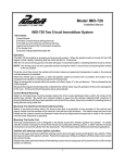
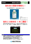
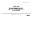
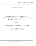
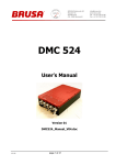
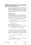
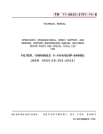
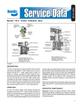
537A Coaxial Frequency Meter
Operating Note
Manual part number: 00536-90013
Printed in USA
March 2001
Supersedes: May 2000
Documentation Warranty
THE MATERIAL CONTAINED IN THIS DOCUMENT IS PROVIDED "AS IS," AND IS
SUBJECT TO BEING CHANGED, WITHOUT NOTICE, IN FUTURE EDITIONS. FURTHER, TO THE MAXIMUM EXTENT PERMITTED BY APPLICABLE LAW, AGILENT
DISCLAIMS ALL WARRANTIES, EITHER EXPRESS OR IMPLIED WITH REGARD TO
THIS MANUAL AND ANY INFORMATION CONTAINED HEREIN, INCLUDING BUT
NOT LIMITED TO THE IMPLIED WARRANTIES OF MERCHANTABILITY AND FITNESS FOR A PARTICULAR PURPOSE. AGILENT SHALL NOT BE LIABLE FOR
ERRORS OR FOR INCIDENTAL OR CONSEQUENTIAL DAMAGES IN CONNECTION
WITH THE FURNISHING, USE, OR PERFORMANCE OF THIS DOCUMENT OR ANY
INFORMATION CONTAINED HEREIN. SHOULD AGILENT AND THE USER HAVE A
SEPARATE WRITTEN AGREEMENT WITH WARRANTY TERMS COVERING THE
MATERIAL IN THIS DOCUMENT THAT CONFLICT WITH THESE TERMS, THE WARRANTY TERMS IN THE SEPARATE AGREEMENT WILL CONTROL.
DFARS/Restricted Rights Notice
If software is for use in the performance of a U.S. Government prime contract or
subcontract, Software is delivered and licensed as “Commercial computer software” as
defined in DFAR 252.227-7014 (June 1995), or as a “commercial item” as defined in FAR
2.101(a) or as “Restricted computer software” as defined in FAR 52.227-19 (June 1987) or
any equivalent agency regulation or contract clause. Use, duplication or disclosure of
Software is subject to Agilent Technologies’ standard commercial license terms, and
non-DOD Departments and Agencies of the U.S. Government will receive no greater than
Restricted Rights as defined in FAR 52.227-19(c)(1-2) (June 1987). U.S. Government users
will receive no greater than Limited Rights as defined in FAR 52.227-14 (June 1987) or
DFAR 252.227-7015 (b)(2) (November 1995), as applicable in any technical data.
Printing Copies of Documentation from the Web
To print copies of documentation from the Web, download the PDF file from the Agilent
web site:
• Go to http://www.agilent.com.
• Enter the document’s part number (located on the title page) in the Quick Search box.
• Click GO.
• Click on the hyperlink for the document.
• Click the printer icon located in the tool bar.
Contacting Agilent
This information supersedes all prior HP contact information.
Online assistance: www.agilent.com/find/assist
Americas
Brazil
(tel) (+55) 11 3351 7012
(fax) (+55) 11 3351 7024
Mexico
(tel) 1 800 254 2440
(fax) 1 800 254 4222
Canada
(tel) +1 877 894 4414
(fax) +1 303 662 3369
United States
(tel) 800 829 4444
(alt) (+1) 303 662 3998
(fax) 800 829 4433
Asia Pacific and Japan
Australia
(tel) 1 800 225 574
(fax) 1 800 681 776
(fax) 1 800 225 539
China
(tel) 800 810 0508
(alt) 800 810 0510
(fax) 800 810 0507
(fax) 800 810 0362
Hong Kong
(tel) 800 933 229
(fax) 800 900 701
India
(tel) 1600 112 626
(fax) 1600 112 727
(fax) 1600 113 040
Japan (Bench)
(tel) 0120 32 0119
(alt) (+81) 426 56 7799
(fax) 0120 01 2144
Japan (On-Site)
(tel) 0120 802 363
(alt) (+81) 426 56 7498
(fax) (+81) 426 60 8953
Singapore
(tel) 1 800 275 0880
(fax) (+65) 6755 1235
(fax) (+65) 6755 1214
South Korea
(tel) 080 778 0011
(fax) 080 778 0013
Taiwan
(tel) 0800 047 669
(fax) 0800 047 667
(fax) 886 3492 0779
Thailand
(tel) 1 800 2758 5822
(alt) (+66) 2267 5913
(fax) 1 800 656 336
Malaysia
(tel) 1800 880 399
(fax) 1800 801 054
Europe
Finland
(tel) (+358) 10 855 2100
(fax) (+358) (0) 10 855 2923
Austria
(tel) 0820 87 44 11*
(fax) 0820 87 44 22
Belgium
(tel) (+32) (0)2 404 9340
(alt) (+32) (0)2 404 9000
(fax) (+32) (0)2 404 9395
Denmark
(tel) (+45) 7013 1515
(alt) (+45) 7013 7313
(fax) (+45) 7013 1555
France
(tel) 0825 010 700*
(alt) (+33) (0)1 6453 5623
(fax) 0825 010 701*
Germany
(tel) 01805 24 6333*
(alt) 01805 24 6330*
(fax) 01805 24 6336*
Israel
Ireland
(tel) (+353) (0)1 890 924 204 (tel) (+972) 3 9288 500
(alt) (+353) (0)1 890 924 206 (fax) (+972) 3 9288 501
(fax)(+353) (0)1 890 924 024
Italy
(tel) (+39) (0)2 9260 8484
(fax) (+39) (0)2 9544 1175
Luxemburg
(tel) (+32) (0)2 404 9340
(alt) (+32) (0)2 404 9000
(fax) (+32) (0)2 404 9395
Netherlands
(tel) (+31) (0)20 547 2111
(alt) (+31) (0)20 547 2000
(fax) (+31) (0)20 547 2190
Russia
(tel) (+7) 095 797 3963
(alt) (+7) 095 797 3900
(fax) (+7) 095 797 3901
Spain
(tel) (+34) 91 631 3300
(alt) (+34) 91 631 3000
(fax) (+34) 91 631 3301
Sweden
(tel) 0200 88 22 55*
(alt) (+46) (0)8 5064 8686
(fax) 020 120 2266*
Switzerland (French)
(tel) 0800 80 5353 opt. 2*
(alt) (+33) (0)1 6453 5623
(fax) (+41) (0)22 567 5313
Switzerland (German)
(tel) 0800 80 5353 opt. 1*
(alt) (+49) (0)7031 464 6333
(fax) (+41) (0)1 272 7373
Switzerland (Italian)
(tel) 0800 80 5353 opt. 3*
(alt) (+39) (0)2 9260 8484
(fax) (+41) (0)22 567 5314
United Kingdom
(tel) (+44) (0)7004 666666
(alt) (+44) (0)7004 123123
(fax) (+44) (0)7004 444555
(tel) = primary telephone number; (alt) = alternate telephone number; (fax) = FAX number; * = in country number
11/16/04
Safety and Regulatory Information
Review this product and related documentation to familiarize yourself with
safety markings and instructions before you operate the instrument. This
product has been designed and tested in accordance with international
standards.
WARNING
The WARNING notice denotes a hazard. It calls attention to a procedure,
practice, or the like, that, if not correctly performed or adhered to, could result
in personal injury. Do not proceed beyond a WARNING notice until the
indicated conditions are fully understood and met.
CAUTION
The CAUTION notice denotes a hazard. It calls attention to an operating
procedure, practice, or the like, which, if not correctly performed or adhered
to, could result in damage to the product or loss of important data. Do not
proceed beyond a CAUTION notice until the indicated conditions are fully
understood and met.
Instrument Markings
!
When you see this symbol on your instrument, you should refer to the instrument’s
instruction manual for important information.
This symbol indicates hazardous voltages.
The laser radiation symbol is marked on products that have a laser output.
This symbol indicates that the instrument requires alternating current (ac) input.
The CE mark is a registered trademark of the European Community. If it is
accompanied by a year, it indicates the year the design was proven.
The CSA mark is a registered trademark of the Canadian Standards Association.
1SM1-A
This text indicates that the instrument is an Industrial Scientific and Medical Group 1
Class A product (CISPER 11, Clause 4).
This symbol indicates that the power line switch is ON.
This symbol indicates that the power line switch is OFF or in STANDBY position.
Agilent 537A Operating And Service Manual
Safety Earth
Ground
This is a Safety Class I product (provided with a protective earthing
terminal). An uninterruptible safety earth ground must be provided from the
main power source to the product input wiring terminals, power cord, or
supplied power cord set. Whenever it is likely that the protection has been
impaired, the product must be made inoperative and secured against any
unintended operation.
Before Applying Power
Verify that the product is configured to match the available main power
source as described in the input power configuration instructions in this
manual. If this product is to be powered by autotransformer, make sure the
common terminal is connected to the neutral (grounded) side of the ac power
supply.
Agilent 537A Operating And Service Manual
Overview
Description
The Agilent 537A coaxial frequency meter is used for measuring frequency
in the 0.96 to 12.4 GHz range. Accuracy is obtained from the spiral scale.
The meter contains a coaxial line coupled to a quarter-wavelength coaxial
resonant cavity loaded with capacitance at the bottom of the band. At
resonance, power is absorbed by the cavity, producing a dip in the coaxial
line power. The frequency at which this dip occurs is read directly from the
dial in gigahertz.
Tuning is accomplished by moving a piston. A precision lead screw, which is
spring-loaded to prevent backlash, is used to position the piston in the cavity.
Due to the design of the cavity, its electrical length is extended at lower
frequencies, and there are no spurious modes.
Specifications
The instrument specifications are provided in Table 1 on page 1.
Table 1
Specifications
Characteristic
Value
Frequency range
3.7 to 12.4 GHz
Reflection coefficient off-resonance
0.33 (2.0 SWR, 9.5 dB return lost)
Calibration increments
10 MHz
Dimensions
Height
Diameter
1
5-3/4 in (146 mm)
3-1/2 in (89 mm)
Weight
3-1/2 lb (1.6 kg)
Dip at resonance
1 dB (minimum)
Dial accuracy 2
±0.1%
1. Width (including connector): 4-5/8in (118 mm).
2. Overall Accuracy: ±0.17% which includes allowance of ±0.02% for 0 to 100% relative humidity,
±0.0016 per ×C from 13 to 33×C and 0.03% backlash.
Measurement
A detector and indicator are required to indicate the dip in coaxial line power
at resonance. It is recommended that 10 dB of attenuation be placed between
the signal source and the frequency meter. If insufficient power is available
to use a 10 dB attenuator, an attenuator offering less attenuation may be
used, to a minimum of 3 dB. The attenuator prevents a shift in the frequency
of the signal source due to line impedance changes at resonance.
Agilent 537A Operating Manual 1
Overview
The detector-indicator combination can be a thermistor mount and power
meter such as the Agilent 478A and 432A, or a crystal detector and SWR
meter. If a SWR meter is used as the indicator, the signal source must be
modulated at 1000 Hz (sine or square wave modulation). For visual display,
an oscilloscope can be used as the indicator. When using an oscilloscope for
swept frequency displays, be sure to sweep the oscilloscope at the same rate
as the signal source. Resonance will be noted as a dip in the oscilloscope
pattern
CAUTION
Do NOT run dial into stops at either end of dial
If frequency measurement is one part of the measurement procedure, be sure
to move meter off resonance before proceeding with other measurements.
Figure 1
Connectors
Type-N Connector Dimensions
The input and output connectors are type-N, female and are compatible with
connectors whose dimensions conform to MIL-C-39012.
N-female Pin Depth: 0.207 to 0.201 in (effective 0 to –0.006)
2 Agilent 537A Operating Manual
Performance Test
Performance Test
Purpose
The procedures listed in Table 2 and Figure 3 on page 7 check performance
for incoming inspection, periodic evaluation, and calibration. The tests are
performed without access to the instrument interior. The performance
standards are contained in Table 1 on page 1.
Recommended Test
Equipment
Test instruments required to make the performance checks are listed in
Table 2. Instruments other than those listed may be used provided their
performance equals or exceeds the critical specifications given.
Table 2
Recommended Test Equipment
Instrument
Critical Specifications
Suggested Agilent Model
Use 1
Sweep Oscillator
CW and swept-frequency signal in
0.96 to 12.4 GHz range
8620C Mainframe (with
appropriate RF plugins)
P,T
779D
P,T
Output: at least +7 dBM
Directional Coupler
Frequency: 1.7 to 12.4 GHZ,
Directivity: >26 dB
Crystal Detector
Frequency: 0.96 to 12.4 GHZ,
Sensitivity: >0.4 mV/,uW
P,T
Oscilloscope
Vert. Sens: <20 mV/dm, Horiz.
Sensitivity: <1 V/cm
P,T
Counter
Frequency: 0.96 to 12.4 GHZ,
Sensitivity: <–7 dBm
P,T
1. P= performance tests, T= troubleshooting.
Maintenance
For dial-stop gear replacement and/or instrument recalibration, refer to
Figure 4 on page 12. For any other repair needs, contact your local Agilent
Technologies Sales and Service office for instructions and assistance.
Return Loss
Specifications
537A reflection coefficient off-resonance: 0.35 (2.0 SWR, 9.5 dB return
loss).
Description
As shown in Figure 2 on page 4, two detectors are connected together with a
modulator, swept amplitude analyzer, and a dual directional coupler in a
reflectometer test setup. The reflectometer is calibrated using a short. The
537A coaxial frequency meter under test is connected and the return
measured.
Agilent 537A Operating Manual 3
Performance Test
Figure 2
Table 3
Return Loss Test Setup
Equipment
Instrument Type
Suggested Agilent Model
GHz or Connector type
Sweep oscillator
8620C mainframe (with
appropriate RF plugins)
–
Dual directional coupler 1
778D
779D
110 MHz to 2 GHz
1.7 to 12.4 GHz
Detectors (2 required)
–
Modulator
–
Swept amlitude analyzer/oscilloscope
–
Coaxial short
Type-N female
Type -N male
APC-7
Low-Pass Filter(s)
700 MHz cutoff
1.2 GHz cutoff
2.2 GHz cutoff
4.1 GHz cutoff
Termination(s)
APC-7
Type-N male
1. Two single directional couplers connected as a dual directional coupler can also be used.
4 Agilent 537A Operating Manual
Performance Test
Procedure
1. Connect the equipment as shown in Figure 2.
2. Set the analyzer control to 0 dB.
3. Set CHANNEL A OFFSET CAL switch to OFF
4. Press CHANNEL A DISPLAY POSITION push button.
5. Adjust CHANNEL A screwdriver adjustment marked POSITION to
place trace on the center graticule. Increase resolution and make fine
adjustment.
6. Place short on reflectometer.
7. Press CHANNEL A push buttons marked DISPLAY R and 10 dB/DIV
8. Set the sweep oscillator to sweep the band of interest.
9. Adjust the sweep oscillator output power level to place the trace on the
second graticule below the center graticule. (Power input is –20 dBm to
the R detector.)
10. Press CHANNEL A push button marked DISPLAY A/R.
11. Turn CHANNEL A OFFSET CAL control to ON and adjust the
OFFSET CAL control to place the trace on the center graticule.
12. Increase the dB/DIV resolution by steps to 0.25 dB/DIV if necessary,
adjust the OFFSET CAL control to return the trace to the center
graticule.
13. Disconnect the short from the reflectometer test port.
14. Connect the 537A under test to the reflectometer test port by
disconnecting the short and inserting the properly terminated 537A
under test.
15. Use CHANNEL A OFFSET dB thumbwheel to return the trace to the
center of the screen, or as close as possible.
16. Read the return loss at the CHANNEL A OFFSET dB window and on
the oscilloscope. Return loss is the total indication of both the
CHANNEL A OFFSET dB window and the trace on the oscilloscope.
Add the trace indication to the window reading if the trace is below the
center graticule, subtract if above.
Agilent 537A Operating Manual 5
Performance Test
17. Return loss measured should be equal to or greater than the following
limits:
Table 4
Return Loss Limits
Lower Limit of Reading
Coupler Directivity
Specification
26 dB
30 dB
40 dB
20.8 dB
27.8 dB
24.6 dB
21.9 dB
9.5 dB
11.0 dB
10.5 dB
9.8 dB
18. If the above limits are not met, test the 537A using a slotted line at the
frequency in question.
6 Agilent 537A Operating Manual
Overall Accuracy
Overall Accuracy
Specification for the 537A: ±0.17% overall accuracy.
Description
A sweep oscillator, 537A under test, detector, and oscilloscope are
connected in series. The sweep oscillator is set to AF to sweep the band in
question. The 537A is set to the frequency in question and the notch located
on the trace. The sweep oscillator is set to CW and adjusted to the center of
the absorption notch of the 537A. The frequency of the sweep oscillator is
measured with a counter and compared with the specifications in Table 1 on
page 1. The sweep oscillator is set to automatic sweep and the notch depth
across the band is checked.
Figure 3
Table 5
Overall Accuracy Test Setup
Test Instruments
Instrument Type
Suggested Agilent Model
Sweep Oscillator
8620C mainframe (with
appropriate RF plugins)
86222A/B
86235A
86240C
86245A
Directional Coupler
779D
Crystal Detector
423A
Oscilloscope
1740A
Counter
5342A
Frequency Range (GHz)
0.5 to 2.4
1.7 to 4.3
3.6 to 8.6
5.9 to 12.4
Agilent 537A Operating Manual 7
Overall Accuracy
Procedure
1. Connect the equipment as shown in Figure 3 on page 7.
2. Set oscilloscope for a vertical sensitivity of about .02 V/cm (ac) and
horizontal sensitivity of about 1 V/cm.
3. Set sweep oscillator for ^F automatic sweep of about 3.8 GHz + 12 MHz
for 537A.
4. Set the 537A to 3.8 GHz.
5. Locate the frequency meter notch and center it on the display by
adjusting the sweep limits on the sweep oscillator.
6. Set the sweep oscillator to CW and adjust the frequency to the center of
the notch (lowest indication on the oscilloscope).
7. Read the frequency on the counter. Frequency should be within the
specifications given in Table 1 on page 1.
8. Repeat above procedure every 200 MHz across the band.
9. Set sweep oscillator to automatic sweep and tune the 537A across
frequency range of sweep oscillator. The notch travel across the
frequency range should cause at least the notch depth given in Table 1-1.
Stop Gear Replacement
Procedure
1. Upon completion of the stop gear replacement it will be necessary to
check the frequency calibration of the instrument.
2. The following special tool is required for this procedure. A Waldes No. 3
Truarc pliers with tips bent 45 degrees.
3. For the following procedures refer to Figure 4 on page 12 and Figure 1
on page 1.
Disassembly Procedure
(Numbers in parentheses refer to numbers on drawing in Figure 4. To replace
the stop gear, proceed as follows:
1. Remove knob (1).
2. Scribe dial position to give approximate location of dial on dial holder.
Do not use pencil as this may be inadvertently erased.
3. Unscrew dial-window retaining nut (3).
4. Remove nut and window
5. Loosen two No. 6 Allen set-screws (9) holding dial. These are located on
the inside or dial holder (10).
6. Turn dial holder until cap (7) is approximately flush with top of dial
holder (near high frequency stop position).
7. Scribe a line from lead screw on plunger to cap for later alignment.
8 Agilent 537A Operating Manual
Overall Accuracy
8. Loosen both No. 6 Allen set screws (9) holding cap in place on lead
screw. These are internal and may be found by looking through the two
inspection holes in dial holder. These are spaced approximately 90
degrees apart.
9. While holding cap in place, back out both screws sufficiently to allow
removal of cap. This should be approximately three full turns of the
Allen screw. If spring and cap jump out, replace them with big-diameter
end of spring at bottom.
CAUTION
Do not turn or remove plunger.
10. Turn the 537A upside down and remove the Truarc retaining-ring
holding dial holder (3). (This requires special Truarc pliers. It may be
necessary to adapt some of your own tools to the job of removing the
retaining ring.).
11. Lift 537A off dial holder and place base assembly upright again.
Examine both sections for pieces of broken stop gear.
12. Inspect bearing and gear rack to make sure that these hasn’t been
damaged by portions of the broken stop gear. If any of the internal
workings other than stop gear have been damaged, it will be necessary to
return to the factory for a major rebuilding.
Reassembly Procedure
1. Replace dial holder, taking care not to damage gears when engaging stop
gear with gear rack
2. Check rotation of the dial holder. There should be approximately 11-1/4
turns of the dial. If not, disengage and try again with a new gear position.
3. When the stop gear is positioned to give approximately 11-1/4 turns
from stop to stop, secure dial holder with the Truarc retaining ring. Make
sure ring is seated properly on inside groove of dial holder.
4. Turn dial holder to stop at high-frequency end of dial.
5. Insert spring into dial holder.
6. Replace cap by compressing spring. Note alignment of cap and lead
screw. See steps 6 thru 9 of disassembly procedure.
7. Tighten both No. 6 Allen set-screws holding cap to lead screws.
8. Turn from stop to stop. Check for binding or other erratic behavior. It
may be necessary to make slight adjustments in cap position so that no
binding occurs during rotation.
9. Turn dial holder counterclockwise (toward lower frequency) to expose
dial retaining set screws.
Agilent 537A Operating Manual 9
Overall Accuracy
10. Place dial on dial holder and check alignment with scribe mark of step 2.
11. Tighten both No. 6 Allen set-screws to hold dial in place.
CAUTION
Do not tighten excessively as knob may not slip into place over the dial/dial
holder.
12. Turn dial clockwise near the stop at the high-frequency end and place
both cursors (6) into the dial grooves to indicate approximately 12.4
GHz.
13. Carefully replace window making sure that cursors ride in the window
grooves.
14. Align window with base. Window keys must be in the window retention
grooves.
15. Replace window-retaining nut.
16. Turn from stop to stop. Check for binding or other erratic behavior. It
may be necessary to make slight adjustments in screw tightness or dial
position so that no binding occurs during dial rotation.
17. When assured of smooth operation, check calibration. Calibration
should be reasonably close if care was taken in alignment of the cap lead
screw and dial. Replace knob.
10 Agilent 537A Operating Manual
Calibration Procedure
Calibration Procedure
Test equipment recommended for testing the 537A are listed in Table 2 on
page 3. Test equipment other than that recommended may be substituted if
their performance equals or exceeds the minimum required specifications
given. Figure 2 on page 4 and Figure 3 on page 7 list procedures for
checking instrument specifications. If dial accuracy is not within listed
specifications, adjust 537A as detailed in the Calibration Alignment
Procedure, as follows.
Calibration Alignment
Procedure
If dial accuracy of the 537A is not within specifications. The following
procedure can be used for readjustment.
1. Remove knob (1).
2. Remove base (11) retaining screws. With base retaining screws
removed, place the 537A in upright position and make electrical hookup
for OVERALL ACCURACY TEST.
3. In the original high-frequency end setting, 12.4 GHz is set almost
one-half turn (about 150 degrees) counterclockwise from the stop. The
dial (5) is held to the dial holder (10) by two set screws (9). Check
frequency accuracy at 12.4 GHz, and if not within overall accuracy
specification, loosen set screws (9) and slip dial. The set screws are
loosened from inside the dial holder; the dial must be rotated about 6
turns before the access holes become visible.
4. The low-frequency end adjustment is made at 3.7 GHz by moving
capacitive load with two cap screws. This adjustment should not change
the high frequency setting.
5. Check dial accuracy in vicinity of 3.7 to 4.1 and 8.2, 12.0, and 12.4
GHz. Reposition the dial, or capacitive load if a compromise is
necessary
6. If accuracy specifications cannot be met, further disassembly is not
recommended. The unit should be returned to your local Agilent
Technologies Sales and Service office.
7. Replace base and knob.
Agilent 537A Operating Manual 11
Calibration Procedure
Figure 4
537A Repair and Recalibration.
12 Agilent 537A Operating Manual
Replaceable Parts
Replaceable Parts
Table 6
Replaceable Parts
Reference
Designator 1
Description
Part Number
Quantity
1
Knob
5040–6950
1
2
Screw, set 8-32 x 3/16
3030–0001
2
3
Nut, dial window retainer
00532–40005
1
4
Window
K532A–18
1
5
Dial
00537–20031
1
6
Cursor
K532A-20
2
7
Cap
R532A–16
1
8
Spring, lead screw
1460–0044
1
9
Screw, set 6-32 x 1/4
3030–0106
2
10
Holder, dial
P532A–4
1
11
Base
00537–20029
1
12
Ring retaining
0510–0069
1
13
Coupling loop assembly
00537–601
14
Bearing, ball
1410–0005
15
Window support
00537–206
16
Screw, fill Hd 2-56 x 1/4
0520–0012
17
Shaft stop gear
P532A–5
1
18
Gear stop
P532A–19
1
19
Ring, retaining
0510–0070
1
20
Cork ring
2190–0345
1
1
1. See Figure 4 for parts location.
Agilent 537A Operating Manual 13