1
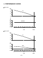
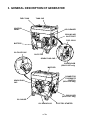
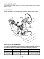
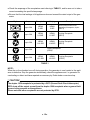
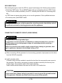
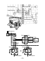
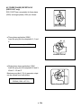
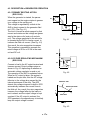
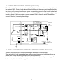
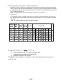
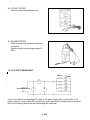
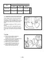
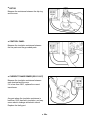
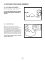
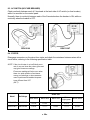
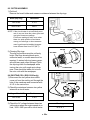
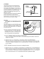
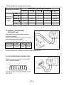
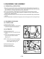
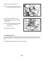
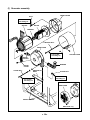
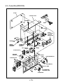
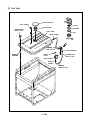
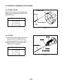
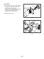
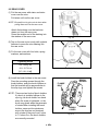
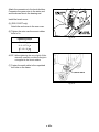
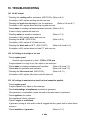
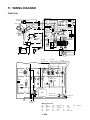
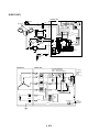
SERVICE MANUAL Models RGV12100 / 13100T GENERATORS PUB-GS1328 Rev. 09/01 CONTENTS Section Title Page 1. SPECIFICATIONS ・ ・ ・ ・ ・ ・ ・ ・ ・ ・ ・ ・ ・ ・ ・ ・ ・ ・ ・ ・ ・ ・ ・ ・ ・ 1 2. PERFORMANCE CURVES ・ ・ ・ ・ ・ ・ ・ ・ ・ ・ ・ ・ ・ ・ ・ ・ ・ ・ ・ ・ ・ 2 3. GENERAL DESCRIPTION OF GENERATOR ・ ・ ・ ・ ・ ・ ・ ・ ・ ・ ・ ・ ・ ・ 3 4. CONSTRUCTION AND FUNCTION ・ ・ ・ ・ ・ ・ ・ ・ ・ ・ ・ ・ ・ ・ ・ ・ ・ ・ 6 4-1 CONSTRUCTION ・・・・・・・・・・・・・・・・・・・・・・・・・・・・・ 6 4-2 FUNCTION ・・・・・・・・・・・・・・・・・・・・・・・・・・・・・・・・ 6 4-3 DESCRIPTION of GENERATOR OPERATION ・・・・・・・・・・・・・・・・ 17 5. SAFETY PRECAUTIONS ・ ・ ・ ・ ・ ・ ・ ・ ・ ・ ・ ・ ・ ・ ・ ・ ・ ・ ・ ・ ・ ・ 19 6. RANGE OF APPLICATIONS ・ ・ ・ ・ ・ ・ ・ ・ ・ ・ ・ ・ ・ ・ ・ ・ ・ ・ ・ ・ ・ 20 7. MEASURING PROCEDURES ・ ・ ・ ・ ・ ・ ・ ・ ・ ・ ・ ・ ・ ・ ・ ・ ・ ・ ・ ・ 23 7-1 MEASURING INSTRUMENTS ・・・・・・・・・・・・・・・・・・・・・・・ 23 7-2 AC OUTPUT MEASURING ・・・・・・・・・・・・・・・・・・・・・・・・・ 24 7-3 MEASURING INSULATION RESISTANCE ・・・・・・・・・・・・・・・・・・ 25 8. CHECKING FUNCTIONAL MEMBERS ・ ・ ・ ・ ・ ・ ・ ・ ・ ・ ・ ・ ・ ・ ・ ・ 27 8-1 PILOT LAMP and VOLTMETER ・・・・・・・・・・・・・・・・・・・・・・・ 27 8-2 AC RECEPTACLES ・・・・・・・・・・・・・・・・・・・・・・・・・・・・ 27 8-3 AC SWITCH (NO-FUSE BREAKER) ・・・・・・・・・・・・・・・・・・・・・ 28 8-4 STATOR ・・・・・・・・・・・・・・・・・・・・・・・・・・・・・・・・・ 28 8-5 ROTOR ASSEMBLY ・・・・・・・・・・・・・・・・・・・・・・・・・・・・ 29 8-6 EXCITING COIL ・・・・・・・・・・・・・・・・・・・・・・・・・・・・・・ 29 8-7 BRUSH ・・・・・・・・・・・・・・・・・・・・・・・・・・・・・・・・・ 30 8-8 A.V.R (AUTOMATIC VOLTAGE REGULATOR) ・・・・・・・・・・・・・・・・ 30 8-9 CURRENT TRANSFORMER (RGV13100T only) ・・・・・・・・・・・・・・・ 31 8-10 ECU (ELECTRONIC CONTROL UNIT) ・・・・・・・・・・・・・・・・・・・ 31 8-11 IDLE CONTROL UNIT (RGV12100 only) ・・・・・・・・・・・・・・・・・・ 32 8-12 DIODE UNIT (RGV13100T only) ・・・・・・・・・・・・・・・・・・・・・・ 33 9. DISASSEMBLY and REASSEMBLY ・ ・ ・ ・ ・ ・ ・ ・ ・ ・ ・ ・ ・ ・ ・ ・ ・ 34 9-1 PREPARATION and PRECAUTIONS ・・・・・・・・・・・・・・・・・・・・ 34 9-2 DISASSEMBLY PROCEDURES ・・・・・・・・・・・・・・・・・・・・・・・ 34 9-3 COMPONENT PARTS ・・・・・・・・・・・・・・・・・・・・・・・・・・・ 35 9-4 GENERATOR ASSEMBLING PROCEDURES・・・・・・・・・・・・・・・・・ 40 10. TROUBLESHOOTING ・ ・ ・ ・ ・ ・ ・ ・ ・ ・ ・ ・ ・ ・ ・ ・ ・ ・ ・ ・ ・ ・ ・ 44 10-1 NO AC OUTPUT ・・・・・・・・・・・・・・・・・・・・・・・・・・・・・ 44 10-2 AC VOLTAGE IS TOO HIGH OR TOO LOW ・・・・・・・・・・・・・・・・・ 44 10-3 AC VOLTAGE IS NOMINAL AT NO-LOAD, BUT LOAD CANNOT BE APPLIED ・・ 44 10-4 ENGINE DOSE NOT RUN ・・・・・・・・・・・・・・・・・・・・・・・・・ 45 11. WIRING DIAGRAM ・ ・ ・ ・ ・ ・ ・ ・ ・ ・ ・ ・ ・ ・ ・ ・ ・ ・ ・ ・ ・ ・ ・ ・ 46 NOTE This Service Manual excludes information for engine. As for the total servicing information as a generator set, please refer in conjunction with the Robin EH63-65 OHV Engine Service Manual. − 04− − 1. SPECIFICATIONS Model Type RGV12100 RGV13100T Brush, Self-exciting, 2-pole, Single phase Brush, Self-exciting, 2-pole, 3-phase Alternator Rated frequency Rated voltage 60Hz 120V / 240V 120V / 208V Maximum output 12000VA 13000VA Rated output 9500VA 10000VA Power factor 1.0 0.8 A.V.R type C.T. type EH65D EH63D Voltage regulator Model Engine Type V-Twin cylinder, Air-cooled, 4-stroke, Overhead valve engine Displacement 653 cm3 Maximum output Fuel 22 HP/ 3600 rpm 18 HP/ 3600 rpm Unleaded automobile gasoline (RON87 or higher) Oil capacity 1.55 liters Starting system Electric starter Fuel tank capacity 44 liters 3/4 Rated Approx. 9.0 hours Approx. 9.7 hours Rated Approx. 8.2 hours Approx. 8.9 hours Noise level Rated (dB-7m) 77.0 dB 77.0 dB Dimensions Rated continuous operation per a tankful of fuel Length 826 mm Width 611 mm (752 mm *1) Height 771 mm (845 mm *1) Dry weight *1: ( *2: ( 141 kg (149 kg *2) ) shows dimensions with castors. ) shows dry weight with castors installed. − 1− − 143 kg (151 kg *2) 2. PERFORMANCE CURVES RGV12100 (Hz) 63 Hz 62 61 60 (V) 250 (125) 240V/120V 240 (120) 230 (115) 220 (110) 0 1/2 4/4 Load Rated RGV13100T (Hz) 63 Hz 62 61 60 (V) 230 208V 220 210 200 0 − 2− − 1/2 4/4 Load Rated 3. GENERAL DESCRIPTION OF GENERATOR FUEL TANK TANK CAP CONTROL PANEL AIR CLEANER COOLING AIR INLET PORT FUEL COCK BATTERY OIL FILLER CAP OIL FILTER SPARK PLUG CAP CHOKE KNOB (RGV13100T only) MUFFLER CONNECTOR FOR REMOTE CONTROL (RGV12100 only) SPARK PLUG CAP END COVER (RGV13100T only) OIL GAUGE OIL DRAIN PLUG − 3− − ELECTRIC STARTER CONTROL PANEL (RGV12100) OIL PURESSURE WARNING LAMP VOLTMETER NO-FUSE BREAKER PILOT LAMP HOUR METER KEY SWITCH 110 0 120 220 240 IDLE CONTROL SWITCH EARTH (GROUND) TERMINAL CONNECTOR FOR REMOTE CONTROL AC RECEPTACLE (RGV13100T) OIL PURESSURE WARNING LAMP VOLTMETER NO-FUSE BREAKER PILOT LAMP HOUR METER KEY SWITCH 110 0 120 220 24 0 AC RECEPTACLE EARTH (GROUND) TERMINAL AC (THREE PHASE and SINGLE PHASE) RECEPTACLE − 4− − SERIAL NUMBER Serial number is stamped on the label stuck on the end cover. NOTE : Always specify serial number when inquiring about the generator or ordering spare parts in order to get correct parts and accurate service. (RGV13100T) (RGV12100) SERIAL NUMBER stamped label SERIAL NUMBER stamped label − 5− − 4. CONSTRUCTION AND FUNCTION 4-1 CONSTRUCTION BRUSH HOLDER END COVER (RGV13100T only) STATOR BOLT STATOR COMPLETE REAR COVER ROTOR COMPLETE FRONT COVER MOUNT RUBBER BALL BEARING TROUGH BOLT SLIP RING 4-2 FUNCTION 4-2-1 STATOR The stator consists of a laminated silicon steel sheet core, a main coil which is wound in the core slots. − 6− − 4-2-2 ROTOR The rotor consists of a laminated silicon steel sheet core and a field coil which is wound over the core. DC current in the field coil magnetizes the steel sheet core. Two permanent magnets are provided for the primary exciting action (RGV13100T). Slip rings are provided on the rotor shaft to receive DC exciting current from AVR (RGV12100) and diode unit (RGV13100T). 4-2-3 BRUSH / BRUSH HOLDER An exciting current is supplied from the A.V.R to the rotor. The brushes are made of carbon and the brush-holder of plastic. It is necessary to keep the contact pressure between the brushes and slip rings withing specific limits. Thus, care must be taken of brush length. 4-2-4 CURRENT TRANSFORMER / DIODE UNIT (RGV13100T only) The current transformer and diode unit will perform a role to step up the voltage lowered by the load and stabilize the output voltage. 12 3 12 3 12 3 CURRENT TRANSFORMER DIODE UNIT − 7− − 4-2-5 A.V.R (AUTOMATIC VOLTAGE REGULATOR) (RGV12100 only) The automatic voltage regulator employs an electronic circuit to automatically regulate voltage. 4-2-6 ECU (ELECTRONIC CONTROL UNIT) ECU controls the start/stop of an engine enabling the fuel cut while stop. It also automatically stops the engine if an abnormal oil pressure occurs. Function Warning lamp Description of Operation When the lubrication oil pressure drops below the safety limit (Oil pressure becomes less than 1kg/cm2) and/or the engine speed ups above the safety limit (Engine speed increases higher than 4,500 r/min for 7 seconds), the warning lamp repeats turning on and off, and the engine stops automatically. The warning lamp turns off after 3 minutes. When the engine started and reaches 1,050 r/min, the starter motor is automatically stopped. Starter motor control When the engine is operating, the starter motor can not start. − 8− − Function Description of Operation When the key switch or the remote control switch is turned to "START", the fuel cut-off valve of the carburetor opens. When the key switch or the remote control switch is turned to "STOP", the fuel cut-off valve closes. If the starter motor is locked by any reason, the starter motor is shut off automatically after 3 seconds. Fail-safe function When the engine dose not start (engine speed does not reach 1,050 r/min), the starter motor is stopped after 21 seconds. When the remote controller is connected, the electric starter dose not run when the switch of remote controller is turned "OFF" even if the key switch on the generator is turned to "START". When the engine speed increases higher than 4,500 r/min for 7 seconds, the engine is shut down automatically and the warning lamp repeats turning on and off for 3 minutes. Self checking function for warning lamp bulb When the key switch or remote control switch is turned to "START", the warning lamp lights up for a moment to indicate that the bulb for the warning lamp is normal. 4-2-7 IDLE CONTROL UNIT (RGV12100 only) 1 The idle control unit 1 releases throttle valve when the applied load current exceeds 0.04A. The two output wires 2 from the main coils must go through the ZCT 3 in the same direction. NOTE : It is normal that the engine speed goes up for a moment when you turn the key switch to "STOP" while the Idle Control Switch is in "ON" position. − 9− − 3 2 4-2-8 OIL PRESSURE SWITCH The oil pressure switch sends a signal to ECU to stop the engine when the engine oil pressure drops to 1.0 kg/cm2 4-2-9 RELIEF VALVE The relief valve begins to open when the engine's oil pressure increases above 3.0 kg/cm2 OIL FILTER CAMSHAFT OIL PRESSURE SWITCH CRANKSHAFT OIL PUMP RELIEF VALVE OIL PUMP FILTER 4-2-10 AC SWITCH (NO-FUSE BREAKER) The AC switch (no-fuse breaker) protects the generator from getting damage by overloading or short circuit in the appliance. The capacity of AC switch (no-fuse breaker) is as follows ; Model Specification No-fuse Breaker Object of Protection RGV12100 60Hz-120V/240V 39A Total output amperage RGV13100T 60Hz-120V/208V 24A Total output amperage − 10− − 4-2-11 AC Receptacle AC receptacles are used for taking AC output power from the generator. A total of 4 kinds of receptacle, each varying in rated voltage and current from another, are used. As many AC plugs as the receptacles, each matching the corresponding receptacle, are provided. The rated current for each receptacle is shown as follows; CAUTION Be careful not to use the receptacles beyond the specified amperage limits to prevent burning. MAX MAX 20A MAX 30A MAX MAX 30A MAX 20A 50A 20A AC120V 30A or less 20A or less AC 120V / 240V 30A or less 20A or less 50A or less 30A or less 30A or less Total 30A or less Total 50A or less (RGV12100) (RGV13100T) CAUTION To connect the appliance to the locking type receptacle, insert the plug in to the receptacle and then turn it clockwise to lock. − 11− − TWIST ■ Check the amperage of the receptacles used referring to TABLE 1, and be sure not to take a current exceeding the specified amperage. ■ Be sure that the total wattage of all appliances dose not exceed the rated output of the generator. Style Ampere Receptacle AC plug NEMA 5-20R NEMA 5-20P GFCI (Ground Fault Circuit Interrupter) Receptacle, duplex up to 30A NEMA L5-30R NEMA L5-30P Locking Receptacle (REC2) up to 30A NEMA L14-30R NEMA L14-30P Locking Receptacle (REC3) up to 20A (REC1) Locking Receptacle (REC4) up to 50A up to 30A Description NEMA L21-30R NEMA L21-30P Locking Receptacle (REC5) TABLE 1 NOTE : When the no-fuse breaker turns off during operation, the generator is over loaded or the appliance is defective. Stop the generator immediately, check the appliance and / or generator for overloading or detect and have repaired as necessary by Robin dealer or service shop. [CAUTION] The duplex 120V receptacle is protected by a GFCI (Ground Fault Circuit Interrupter). GFCI shuts off the output current from the duplex 120V receptacle when a ground fault occurs in the generator or the appliance. Please note that other receptacles are not protected by GFCI. − 12− − GFCI RECEPTACLE After starting the engine, check the GFCI for proper functioning by the following test procedure. ■ Push blue TEST button, The red RESET button will pop out exposing the word TRIP. Power is now off at the outlets protected by the GFCI, indicating that the device is functioning properly. ■ If TRIP dose not appear when testing, do not use the generator. Call a qualified electrician. ■ To restore power, push RESET button. WARNING If the RESET button pops out during operation, stop the generator immediately and call a qualified electrician for checking generator and the appliances. CONNECTING TO DOMESTIC CIRCUIT (HOUSE WIRING) WARNING This generator is neutral grounded type. If a generator is to be connected to residential or commercial power lines, such as a stand-by power source during power outage, all connections must be made by a licensed electrician. Failure in connection may result in death, personal injury, damage to generator, damage to appliances, damage to the building's wiring or fire. (a) When connecting a Robin generator to a house wiring, generator output power must be taken from the 240V-4P receptacle. (b) Install a transfer switch. A transfer switch must be installed to transfer the load from the commercial power source to the generator. This switch is necessary to prevent accidents caused by the recovery from power outage. Use a transfer switch of the correct capacity. Install transfer switch between the meter and the fuse or AC breaker box. [CAUTION] If the neutral wire of house wiring is grounded, be sure to ground the ground terminal of the generator, Otherwise an electric shock may occur to the operator. − 13− − UTILITY HIGH LINE MAIN POWER LINE CONNECTING BOX 240V RECEPTACLE TRANSFER SWITCH Utility high line House circuit breaker Meter box X W Y 120V appliance 120V appliance X W Y 240V appliance Transfer switch X W Y Generator Generator (W) (W) OR (X) (Y) W (Y) (G) Y X (X) (G) 240V 4P- Receptacle − 14− − 240V 4P- Receptacle (c) Operating the generator. ■ Turn the house AC breaker off before starting the generator. ■ Start the generator and warm it up. ■ Turn the house AC breaker on. [CAUTION] Do not start the generator with electrical appliance (s) connected and with their switches on. Otherwise the appliance (s) may be damaged by the surge voltage at starting. 4-2-12 3-PHASE APPLICATION (RGV13100T only) Connection of Power Cables WARNING ■ Do not touch output terminals while the generator is running or the operator may suffer severe electric shock resulting in death. ■ Be sure to shut down the generator before connecting or changing connection of power cables to the generator. This generator has four output terminals of three phase, four wire system. Connect power cables to the generator output terminals according to the type of application. − 15− − AC (THREE PHASE) RECEPTACLE (RGV13100T only) RGV13100T has a receptacle for three plase (208V) and single phase (120V) as follows : W Z X Y SINGLE PHASE AC120V THREE PHASE AC208V ■ Three phase application (208V) Insert the plug into the receptacle X, Y and Z. W G Z Generator rated output : 10000VA X Y 3-PHASE OUTPUT ■ Single phase lower application (120V) Insert the plug into the receptacle W and X, W and Y, W and Z. Maximum one-third (1/3) of generator output can be utilized from each phase. W G Z X Generator rated output : 3324VA (120V x 27.7A) Y SINGLE-PHASE OUTPUT − 16− − 4-3 DESCRIPTION of GENERATOR OPERATION 4-3-1 PRIMARY EXCITING ACTION (RGV12100) AVR When the generator is started, the permanent magnet on the engine rotates to generator a voltage in the exciting coil. This voltage is regulated by a diode in the AVR to feed a current to the generator field coil. (FC). (See Fig. 4-1) The rotor is turned an electromagnet by that current and rotates so that voltage are generated in the stator coils (main coil and sub coil). The voltage generated in the sub coils is operated by the AVR to feed a current to increase the field coil current. (See Fig. 4-2) As a result, the rotor magnetism increases. This operation is repeated to generate the rated voltage at 50 Hz or 60 Hz in the main coil and DC coil. FC a EC ENGINE MAGNETO Fig. 4-1 MC 4-3-2 VOLTAGE REGULATING MECHANISM (RGV12100) SC Connect a load to the AC output terminal and increase current. Output voltage varies as shown in Fig. 4-3 depending on whether an automatic voltage regulator is used or not. The operation of the AVR is explained below. When an AC output is taken, the engine is loaded and its rpm falls, Also the AC voltage fails due to the voltage drop caused by the internal resistance of the coils. The AVR detects this voltage drop and its built-in SCR automatically increase the current flows to the field coil. As a result, the rotor magnetism increase, the voltage fallen by the load current is raised, and the output voltage is kept constant. If the AC output is reduced, the SCR operates in the opposite way to similarly keep the output voltage constant. b FC Fig. 4-2 WITHOUT AVR RATED VOLTAGE V WITH AVR A Fig. 4-3 − 17− − AVR 4-3-3 CURRENT TRANSFORMER CONTROL (RGV13100T) When the engine starts, a permanent magnet implanted in the rotor rotates, creating voltage in the main coil (MC). When a load makes contact with the coil, the load current passing through the primary coil of current transformer causes a magnetizing current to flow in ratio to the load current flowing through the current transformer primary coil. This magnetizing current passing through a diode to field coil creates a strong magnetic field in the rotor which falls with the amount of the load, increasing the voltage. GENERATOR CONTROL BOX AC output receptacle (120V : Single phase) (208V : Three phase) REC5 Grn R R 2 3 1 W W 2 3 Y Hour meter Hr No-fuse Pilot breaker PL lamp G R V Y W W Z H X Y G W G 1 Blk Blk 2 3 Y Blk AC output receptacle (120V)REC2 Current transformer Brush Brn Diode unit Feld Winding W Grn/Y AC Winding 1 Voltmeter Grn AC output receptacle (120V) REC1 Brush Grn/W Key switch (-M) Grn/Y Earth (Ground) terminal 4-3-4 THE ADVANTAGES OF CURRENT TRANSFORMER CONTROL (RGV13100T) With AVR control, control is effected according to variations in output voltage. When an inductive load is applied, a large starting current is required (current variations are greater than voltage variation), precise control becomes difficult. Current transformer control, on the other hand, controls the output voltage according to the load current, which is better for using inductive load. − 18− − 5. SAFETY PRECAUTIONS 1. Use extreme caution near fuel. A constant danger of explosion or fire exists. Do not fill the fuel tank while the engine is running. Do not smoke or use open flame near the fuel tank. Be careful not to spill fuel when refueling. If spilt, wipe it and let dry before starting the engine. 2. Do not place inflammable materials near the generator. Be careful not to put fuel, matches, gunpowder, oily cloth, straw, and any other inflammables near the generator. 3. Do not operate the generator in a room, cave or tunnel. Always operate in a well-ventilated area. Otherwise the engine may overheat and also, the poisonous carbon monoxide contained in the exhaust gases will endanger human lives. Keep the generator at least 1 m (3 feet) away from structures or facilities during use. 4. Operate the generator on a level surface. If the generator is tilted or moved during use, there is a danger of fuel spillage and a chance that the generator may tip over. 5. Do not operate with wet hands or in the rain. Severe electric shock may occur. If the generator is wet by rain or snow, wipe it and thoroughly dry it before starting. Don't pour water over the generator directly nor wash it with water. If the generator is wet with water, the insulation's will be adversely affected and may cause current leakage and electric shock. 6. Do not connect the generator to the commercial power lines. This may cause a short-circuit or damage to the generator. 7. Be sure to check and remedy the cause of circuit breaker tripping before re-setting it on. CAUTION : If the circuit breaker tripped off as a result of using an electrical appliance, the cause can be an overload or a short-circuit. In such a case, stop operation immediately and carefully check the electrical appliance and AC plugs for faulty wiring. − 19− − 6. RANGE OF APPLICATIONS Generally, the power rating of an electrical appliance indicates the amount of work that can be done by it. The electric power required for operating an electrical appliance is not always equal to the output wattage of the appliance. The electrical appliances generally have a label showing their rated voltage, frequency, and power consumption(input wattage). The power consumption of an electrical appliance is the power necessary for using it. When using a generator for operating an electrical appliance, the power factor and starting wattage must be taken into consideration. In order to determine the right size generator, it is necessary to add the total wattage of all appliances to be connected to the unit. Refer to the followings to calculate the power consumption of each appliance or equipment by its type. (1) Incandescent lamp, heater, etc. with a power factor of 1.0 Total power consumption must be equal to or less than the rated output of generator. Example : A rated 3000 W generator can turn thirty 100W incandescent lamps on. (2) Fluorescent lamps, mercury lamps, etc. with a smaller power factor Select a generator with a rated output equivalent to 1.2 to 2 times of the power consumption of the load. Example : A 400W mercury lamp requires 600 W to 700 W power source to be turned on. A rated 3000 W generator can power four or five 400 W mercury lamps. NOTE 1 : If a power factor correction capacitor is not applied to the mercury lamp or fluorescent lamp, the more power shall be required to drive those lamps. A rated 3000W generator can drive one or two 400W mercury lamps without power factor correction capacitors. NOTE 2 : Nominal wattage of the fluorescent lamp generally indicates the output wattage of the lamp. Therefore, if the fluorescent lamp has no special indication as to the power consumption, efficiency should be taken into account as explained in item (5) on the following page. (3) Motor driven tools and light electrical appliances Generally the starting wattage of motor driven tools and light electrical appliances are 1.2 to 3 times lager than their running wattage. Example : A rated 250 W electric drill requires a 400 W generator to start it. (4) Initially loaded motor driven appliances such as water pumps, compressors, etc. These appliances require large starting wattage which is 3 to 5 times of running wattage. Example : A rated 900 W compressor requires a 4500 W generator to drive it. NOTE 1 : Motor-driven appliances require the aforementioned generator output only at the starting. Once their motors are started, the appliances consume about 1.2 to 2 times their rated power consumption so that the excess power generated by the generator can be used for other electrical appliances. − 20− − NOTE 2 : Motor-driven appliances mentioned in lets (3) and (4) vary in their required motor starting power depending on the kind of motor and start-up load. If it is difficult to determine the optimum generator capacity, select a generator with a larger capacity. (5) Appliances without any indication as to power consumption Some appliances have no indication as to power consumption; but instead the work load (output) is indicated. In such a case, power consumption is to be worked out according to the numerical formula mentioned below. (Output of electrical appliance) (Efficiency) = (Power consumption) Efficiencies of some electrical appliances are as follows: Single-phase motor ・・・・・・・・・0.6 to 0.75 Three-phase motor・・・・・・・・・・0.65 to 0.9 Fluorescent lamp ・・・・・・・・・・・0.7 to 0.8 The smaller the motor, the lower the efficiency. Example 1 : A 40 W fluorescent lamp means that its luminous output is 40W. Its efficiency is 0.7 and accordingly, power consumption will be 40÷0.7=57W. As explained in Item(2), multiply this power consumption value of 57 W by 1.2 to 2 and you will get the figure of the necessary capacity of a generator. In other words, a generator with a rated output of 1000 W capacity can light nine to fourteen 40W fluorescent lamps. Example 2 : Generally speaking, a 400 W motor means that its work load is 400 W. Efficiency of this motor is 0.7 and power consumption will be 400÷0.7=570 W. When this motor is used for a motor-driven tool, the capacity of the generator should be multiple of 570W by 1.2 to 3 as explained in the Item (3). 570 (W)×1.2 to 3=684 (W) to1710 (W) Applicable Wattage (W) Applications RGV12100 (60 Hz) Incandescent Lamp, Heater 10000 Fluorescent Lamp, Electric Tool 4950 Pump, Compressor 2500 − 21− − NOTES : Wiring between generator and electrical appliances 1. Allowable current of cable Use a cable with an allowable current that is higher than the rated input current of the load (electrical appliance). If the input current is higher than the allowable current of the cable used, the cable will become excessively heated and deteriorate the insulation, possibly burning it out. Table 7-2 shows cables and their allowable currents for your reference. 2. Cable length If a long cable is used, a voltage drop occurs due to the increased resistance in the conductors decreasing the input voltage to the load (electrical product). As a result, the load can be damaged. Table 7-2 shows voltage drops per 100 meters of cable. Allowable No.of strands Resistance current / strands dia. Current Amp. mm2 No. A No./mm Ω/100m 0.75 18 7 30/0.18 2.477 2.5V 8V 12.5V ─ 1.27 16 12 50/0.16 1.486 1.5V 5V 7.5V 12V 15V 18V 2.0 14 17 37/0.26 0.952 1V 3.5 12 to 10 23 45/0.32 0.517 ─ 5.5 10 to 8 35 70/0.32 0.332 ─ 1A 3A 3V 5A 10A 12A 15A ─ ─ ─ ─ 8V 10V 12V 15V 1.5V 2.5V 4V 5V 6.5V 7.5V 1V 5V 8A 2V 2.5V 3.5V 4V Voltage drop Nominal A.W.G. cross Gauge section No. 5V 1 ×R×I× 100 R means resistance (Ω / 100 m) on the above table. I means electric current through the wire (A). means the length of the wire (m). The length of wire indicates round length, it means twice the length from generator to electrical tools. Voltage drop indicates as V= − 22− − 7. MEASURING PROCEDURES 7-1 MEASURING INSTRUMENTS (1) VOLTMETER AC voltmeter is necessary. The approximate AC voltage ranges of the voltmeters to be used for various types of generators are as follows : 0 to 150 V : Type with an output voltage of 110 or 120 V 0 to 300 V : Type with an output voltage of 220, 230 or 240 V 0 to 150 V, 0 to 330 V : Dual voltage type FOR AC (2) AMMETER AC ammeter is necessary. An AC ammeter with a range that can be changed according to the current rating of a given generator is most desirable. (About 10 A, 20 A, 100 A) FOR AC (3) FREQUENCY METER Frequency range : About 45 to 65Hz NOTE : Be careful of the frequency meter's input voltage range. − 23− − (4) CIRCUIT TESTER Used for measuring resistance, etc. (5) MEAGER TESTER Used for measuring generator insulation resistance. Select one with testing voltage range of 500V. 7-2 AC OUTPUT MEASURING SWITCH LOAD A ~ TO AC RECEPTACLE F V ~ Use a circuit above for measuring AC output. A hot plate or lamp with a power factor of 1.0 may be used as a load. Adjust the load and rpm. and check that the voltage range is as specified in the following table at the rated amperage and rated rpm. − 24− − Rated voltage 120 V 208 V 240 V RGV12100 112V-128V -------------- 224V-256V RGV13100T -------------- 218V-249V -------------- 7-3 MEASURING INSULATION RESISTANCE Use a megger tester to check the insulation resistance. Connect a megger tester to one of receptacle output terminals and the ground terminal, then measure the insulation resistance. An insulation resistance of 1MΩ or more is normal. If it is less than 1MΩ, disassemble the generator and measure the insulation resistance of the stator, rotor and control panel individually. ● STATOR (1) Measure the insulation resistance between BLUE (RGV12100), GREEN (RGV13100T) lead and the core. (2) Measure the insulation resistance between WHITE lead and the core. (3) Measure the insulation resistance between BLACK lead and the core. (4) Measure the insulation resistance between RED lead and the core. − 25− − Voltage range Model ● ROTOR Measure the resistance between the slip ring and the core. ● CONTROL PANEL Measure the insulation resistance between the live parts and the grounded parts. ● CURRENT TRANSFORMER (RGV13100T) Measure the insulation resistance between each terminal and the core. If it is less than 1MΩ, replace the current transformer. Any part where the insulation resistance is less than 1MΩ has faulty insulation, and may cause electric leakage and electric shock. Replace the faulty part. − 26− − 8. CHECKING FUNCTIONAL MEMBERS 8-1 PILOT LAMP and VOLTMETER Check the pilot lamp and the voltmeter if it is turned on by applying specific voltage. Pilot lamp and voltmeter cannot be checked with circuit tester because its resistance is too large. 8-2 AC RECEPTACLES Using a circuit tester, check continuity between the two terminals at the rear of the AC receptacles while the receptacle is mounted on the control panel. When continuity is found between the output terminals of the receptacle with a wire connected across these terminals, the AC receptacle is normal. When the wire is removed and no continuity is found between these terminals, the receptacles are also normal. − 27− − PILOT LAMP 8-3 AC SWITCH (NO-FUSE BREAKER) Check continuity between each of 2 terminals at the back side of AC switch (no-fuse breaker) while it is mounted on the control panel. Normally, there is continuity between each of the 2 terminals when the breaker is ON, while no continuity when the breaker is OFF. RGV12100 RGV13100T 8-4 STATOR Disengage connectors on the wires from stator and check the resistance between wires with a circuit tester, referring to the following specification table. NOTE : If the circuit tester is not sufficiently accurate, it may not show the values given and may give erroneous readings. Erroneous readings will also occur when there is a wide variation of resistance among coil windings or when measurement is performed at ambient temperatures different from 20℃ (68 ° F). Stator coil Model Hz/Voltage Red-White Black-Blue Black-Red WhiteLight green Black-White RGV12100 60/120/240 0.11Ω 0.11Ω ------------ 0.37Ω ------------ RGV13100T 60/120/208 0.23Ω ------------ 0.23Ω ------------ 0.23Ω − 28− − 8-5 ROTOR ASSEMBLY 1) Field coil Remove the brush holder and measure resistance between the slip rings. Rotor (Slip ring) Resistance RGV12100 4.11Ω RGV13100T 69.6Ω NOTE : If the circuit tester is not sufficiently accurate, it may not show the values given and may give erroneous readings. Erroneous reading will also occur when there is a wide variation of resistance among coil windings or when measurement is performed at ambient temperatures different from from 20℃(68 ° F). ROTOR 2) Cleaning Slip rings The slip ring surfaces must be uniformly bright. Slip rings showing black spots, excessive wear, or uneven wear must be repaired. A stained slip ring lowers generator efficiency and output voltage. Polish the slip rings with fine sandpaper while turning the rotor until rough spots disappear. Care should be taken not to touch the rotor coils with the sandpaper. 8-6 EXCITING COIL (RGV12100 only) 1) Disconnect the two yellow wires which come out from the exciting coil through the hole of the crankcase and connected with A.V.R. in the control box. 2) Check the resistance between two yellow wires with a circuit tester. Exciting coil for A.V.R. Resistance RGV12100 2.35Ω SLIP RING SANDPAPER Ignition coil Exciting coil Yellow Yellow 3) Check the AC voltage between these two yellow wires when the engine speed at no load ; 3600-3800 rpm with a circuit tester. − 29− − AC voltage 35 to 45 V Charge coil 8-7 BRUSH The brushes must be smooth where they contact the slip rings. If not, polish smooth the brushes with sandpaper. A brush that is not smooth produces arcs between the brush and slip ring leading to possible damage. Usable brush lengths are from 5 mm to 15 mm (0.2 " to 0.6"). A brush shorter than 5 mm must be replaced because decreased contact pressure between the brush and slip ring lowers generator efficiency and output voltage. 8-8 A.V.R (AUTOMATIC VOLTAGE REGULATOR) 1) Features This AVR operates to control the field current in order to maintain the output voltage for the AC current, which generated by the magnetic flux by the field coil. BRUSH HOLDER 15 to 5 mm (0.6" to 0.2") BRUSH 2 4 1 3 Terminal number of the A.V.R. Yellow 2) A.V.R. trouble may be identified by simply looking at the A.V.R., or by the inter-lead resistance with a tester, or actually mounting it in the generator and operating it. (a) A.V.R. TROUBLE IDENTIFICATION by APPEARANCE If an A.V.R. electronic part is burnt dark, or the surface epoxy resin melted, it often indicates A.V.R. trouble. (b) IDENTIFYING A.V.R. TROUBLE by CHECKING INTER-LEAD RESISTANCE Check the inter-lead resistance of the A.V.R. with a tester, referring to the following table. If the tester readings very greatly from the values specified in the table on next page, the A.V.R. is faulty. NOTE : Take teater inaccuracy into account in reading the tester. (c) IDENTIFYING A.V.R. TROUBLE by MOUNTING and OPERATING in THE GENERATOR SCR or transistor damage cannot be detected by simply looking at the A.V.R. or checking the lead resistance. Check it by mounting the suspectedly faulty A.V.R. in a normal generator, or mount a mormal A.V.R. in a generator which fails to generate voltage. − 30− − * Checking table for analogue circuit tester. Apply black - needle of the circuit tester Analogue circuit tester Apply red + needle of the circuit tester Yellow Black 1 White 2 Yellow --------------- ∞ ∞ ∞ ∞ Black 1 ∞ --------------- 200 kΩ ∞ 300 kΩ White 2 ∞ 60 kΩ --------------- ∞ 100 kΩ Light green 3 16 kΩ 350 kΩ 125 kΩ --------------- 14 kΩ Brown 4 orYellow ∞ 250 kΩ 100 kΩ ∞ --------------- 8-9 CURRENT TRANSFORMER (RGV13100T only) Disconnect the connectors and couplers of current transformer. Check the inter-terminal resistance of current transformer with a circuit tester. Terminal number 1 and 2 1 and 3 2 and 3 RGV13100T 2.00Ω 2.00Ω 0.009Ω If current transformer is found to be faulty, replace with new one. 8-10 ECU (ELECTRONIC CONTROL UNIT) Check the resistance between 13 terminals of ECU with circuit tester. 1 2 3 13 12 11 10 4 5 6 9 8 7 Terminal number of the ELECTRONIC CONTROL UNIT − 31− − Light green 3 Brown 4 orYellow Tester (-) Pin No. 1 2 3 4 5 6 7 8 9 !0 !1 !2 !3 1 ------- ∞ 2 ∞ ∞ ∞ ∞ ∞ ∞ ∞ ∞ ∞ ∞ ∞ ∞ ------- ∞ ∞ ∞ ∞ ∞ ∞ ∞ ∞ ∞ ∞ ∞ ∞ ∞ ∞ 18.4M ------- 10M 10.2M 10.4M 11M 14.4M 5.3M ∞ ∞ ∞ ∞ ∞ ∞ ∞ ∞ ∞ ∞ ∞ ∞ ∞ ∞ ∞ ∞ ∞ ∞ ∞ ∞ ∞ ∞ ∞ ∞ ∞ ∞ ∞ ∞ ∞ ∞ ∞ 2675k ∞ ∞ ------- 2590k ∞ ------- ∞ ∞ ∞ ∞ ∞ ∞ 2438k 2664k 4M ------- ∞ ∞ ∞ ∞ ∞ ∞ ∞ ∞ ∞ ∞ 10.3M 11M 14M 5.3M ------- ∞ ∞ ∞ ∞ ∞ ∞ ∞ ∞ ∞ ∞ ∞ ∞ ∞ ∞ ∞ ∞ ∞ ∞ ∞ ∞ ∞ ------- ∞ ∞ ∞ ∞ ∞ ∞ ∞ ∞ ∞ ∞ ∞ ∞ ∞ ------- 3 4 5 Tester ( ) 6 7 8 9 !0 !1 !2 !3 5.3M 18M ∞ ∞ ------0.1 0.1 ------- ∞ ∞ ∞ ∞ ∞ ∞ ∞ ∞ 2392k 2389k 10.3M 10.2M ∞ ∞ ∞ ∞ ------- ∞ ∞ ∞ ∞ ∞ ∞ ∞ ------- 8-11 IDLE CONTROL UNIT (RGV12100 only) Check the resistance between five terminals of IDLE CONTROL UNIT with circuit tester. 1 5 2 4 3 Terminal number of the IDLE CONTROL UNIT Circuit tester (with battery power source 1.5 V) Apply red 〇 + needle of the circuit breaker Apply black 〇 - needle of the circuit breaker 1 2 3 1 ------- ∞ 2 ∞ ------- ∞ ------- 65 3 65 ∞ 4 65 ∞ 65 5 6.5 ∞ 6.5 4 65 ∞ 65 ------6.5 5 30 ∞ 30 30 ------- *Tester measuring range : 1000 k NOTE : The resistance readings vary depending on the types of circuit testers. The above table shows an example of the resistance readings measured by an ordinary analogue circuit tester with 1.5 volt battery power source. It is advisable for you to check the resistance readings using your standard circuit tester and revise the checking table. − 32− − 8-12 DIODE UNIT (RGV13100T only) Check the resistance between five wires of DIODE UNIT with circuit tester. Apply black 〇 - needle of the circuit breaker Diode unit Brown Yellow 1 Apply red 〇 + needle of the cir- Yellow 2 cuit breaker Yellow 3 Light green Brown Yellow 1 Yellow 2 Yellow 3 Light green ------- ∞ ∞ ∞ ∞ 16 ------- ∞ ∞ ∞ 16 ∞ ------- ∞ ∞ 16 ∞ ∞ ------- ∞ 30 16 − 33− − 16 16 ------- 9. DISASSEMBLY AND ASSEMBLY 9-1 PREPARATION and PRECAUTIONS 1) Be sure to memorize the location of individual parts when disassembling the generator so that the generator can be reassembled correctly. Tag the disassembled part with the necessary information to facilitate easier and smoother reassemble. 2) For more convenience, divide the parts into several groups and store them in boxes. 3) To prevent bolts and nuts from being misplaced or installed incorrectly, replace them temporarily to their original position. 4) Handle disassembled parts with care; clean them before reassemble using a neutral cleaning fluid. 5) Use all disassembly / assembly tools properly, and use the proper tool for each specific job. 9-2 DISASSEMBLY PROCEDURES 9-2-1 CONTROL PANEL (1) Remove the front panel. (2) Disconnect the connectors on the wiring from the front panel to the alternator. 9-2-2 ALTERNATOR (1) Remove the end cover. (2) Remove the brush cover and the brush holder. (3) Take off the two flange-nuts and lift the front cover with a piece of lumber. (See Fig. 9-1) Fig. 9-1 NOTE : Lift the front cover until completely the rear cover removes from the mount rubber. (See Fig. 9-2) REAR COVER (4) Remove the rear cover. (5) Remove the bushing. (6) Remove the stator cover. MOUNT RUBBER Fig. 9-2 − 34− − (7) Remove the stator. (See Fig. 9-3) NOTE : The stator is heavy. Be careful do not hit the coil of the stator to the rotor. Fig. 9-3 (8) Loosen the through bolt of the rotor. (9) Remove the rotor with the soft hammer. (See Fig. 9-4) ROTOR THROUGH BOLT NOTE : Temporarily tighten the through bolt of the rotor when hit the rotor. (See Fig. 9-4) (10) Remove the front cover. SOFT HAMMER Fig. 9-4 9-3 COMPONENT PARTS For disassembling and assembling, the following illustrations show the major component parts and their configuration for (1) Generator assembly, (2) Control Box and (3) Fuel Tank and system. The specified tightening torque is indicated in the illustration. − 35− − (1) Generator assembly FRONT COVER BOLT 22.5-24.5Nm 230-250Kg-cm STATOR ROTOR BEARING THROUGH BOLT REAR COVER STATOR COVER 11.8-13.7Nm 120-140Kg-cm BRUSH HOLDER BUSHING BRUSH COVER COVER BOLT GENERATOR BASE FLANGE NUT 11.8-13.7Nm 120-140Kg-cm 11.8-13.7Nm 120-140Kg-cm END COVER MOUNT RUBBER RGV13100T only − 36− − (2-1) Control Box (RGV12100) PLATE CONTROL BOX GROMMET WIRE IDLE CONTROL UNIT A.V.R. (AUTOMATIC VOLTAGE REGULATOR) ECU (P4) CONNECTOR CAP EARTH (GROUND) TERMINAL CONNECTOR for REMOTE CONTROL GROMMET RELAY CLAMP IDEL CONTROL SWITCH AC RECEPTACLE NO-FUSE BREAKER CONTROL PANEL STARTER SWITCH AC RECEPTACLE HOUR METER PILOT LAMP OIL PRESSURE WARNING LAMP VOLTMETER − 37− − (2-2) Control Box (RGV13100T) CURRENT TRANSFORMER PLATE CONTROL BOX DIODE UNIT GROMET 05 EARTH (GROUND) TERMINAL ECU (P4) RELAY GROMMET WIRE CLAMP PILOT LAMP AC RECEPTACLE OIL PRESSURE WARNING LAMP NO-FUSE BREAKER STARTER SWITCH AC RECEPTACLE HOUR METER VOLTMETER CONTROL PANEL − 38− − (3) Fuel Tank FUEL TANK CAP FUEL GAUGE FILTER FUEL FILTER FRANGE BOLT (M6 x 14 mm) PACKING FUEL TANK CUP HOSE CLAMP DETAIL A A RUBBER PIPE (120 mm) FUEL STRAINER RUBBER WASHER PURSE LOCK FLANGE BOLT (M6 x 14 mm) FUEL PUMP HOSE CLAMP RUBBER PIPE (630 mm) − 39− − 9-4 GENERATOR ASSEMBLING PROCEDURES 9-4-1 FRONT COVER FRONT COVER Attach the front cover to the engine main bearing cover. Match the faucet joint and tighten the bolts. WASHER Tightening torque 230-250 kg cm SPRING WASHER 22.5-24.5 N m BOLT 16.6-19.5 ft lbs Fig. 9-5 9-4-2 ROTOR ROTOR (1) Wipe off oil, grease and dust from the tapered portion of engine shaft and matching tapered hole of rotor shaft. (2) Mount the rotor to the engine shaft. Tighten the through bolt. BEARING THROUGH BOLT Tightening torque WASHER SPRING WASHER 120 -140 kg cm 11.8 -13.7 N m 8.7-10.1 ft lbs Fig. 9-6 − 40− − 9-4-3 STATOR (1) Put the stator in the rear cover setting the four grooves on the side of stator with thread holes of the rear cover. Tighten the four bolts tentatively to check if the grooves and thread holes are aligned correctly. (See Fig.9-8) STATOR STATOR COVER (2) Remove the four bolts. Fig. 9-7 Fig. 9-8 − 41− − 9-5 REAR COVER (1) Put the rear cover with stator and stator cover over the rotor. Pull wires out from the rear cover. NOTE : Be careful not to give cuts to wires when pulling them out from the rear cover. Attach the bushing over the lead wire drawn out from the rear cover. Press the smaller end of the bushing into the window of the rear cover. Fig. 9-9 (2) Tap on the rear cover evenly with a plastic hammer to press the rotor bearing into the rear cover. (3) Fix the rear cover with four bolts, spring washers, and washers. Tightening torque 120 -140 kg cm 11.8 -13.7 N m Fig. 9-10 8.7-10.1 ft lbs (4) Install the brush holders in the rear cover. Pass the mounting screws through the brush holders, push the brush holders so that the brushes will be perpendicular to the slip rings, and tighten the screws. NOTE : There are two kinds of brush holders. If a brush is installed oblique to the slip ring, the brush holder can break when the screw is tightened ; or the brush may break when the generator of started.After installing the brush holders, measure the resistances across the brushes and terminals with a tester if they are from 5 ohms to 7.5 ohms.If so, the brush holders are correctly mounted. − 42− − BRUSH HOLDER FLANGE BOLT SCREW BRUSH COVER Fig. 9-11 Attach the connectors to the brush holders. Connector the green wire to the stator end and the brown wire to the bearing end. Install the brush cover. (5) (RGV13100T only) Attach the end cover to the rear cover. (6) Tighten the nuts over the mount rubber bolts to fix. Fig. 9-12 Tightening torque 120 -140 kg cm 11.8 -13.7 N m 8.7-10.1 ft lbs NOTE : When tightening the nuts, slightly lift the alternator assembly so that the weight is not applied to the mount rubbers. (7) Fasten the earth cable to the unpainted bolt hole on the frame. EARTH CABLE Fig. 9-13 − 43− − 10. TROUBLESHOOTING 10-1 No AC output * Checking the exciting coil for resistance. (RGV12100) (Refer to 8-6.) If insulation is NG, replace exciting coil with new one. * Checking the brush and slip ring of rotor for resistance. (Refer to 8-5 and 8-7.) If insulation is NG, replace brush and slip ring with new one. * Check stator for winding resistance between terminals. (Refer to 8-4.) If stator is faulty, replace with new one. * Checking stator for insulation resistance. (Refer to 7-3.) If insulation is NG, replace stator with new one. * Checking the A.V.R . (RGV12100) (Refer to 8-8.) If insulation is NG, replace A.V.R with new one. * Checking the diode unit and C.T . (RGV13100T) (Refer to 8-9 and 8-12.) If insulation is NG, replace diode unit and C.T with new one. 10-2 AC Voltage is too high or too low * Check engine speed. Nominal engine speed at no load ; 3,700 to 3,750 rpm If engine speed is too high or too low, adjust to the rated rpm. * Check stator for winding resistance and insulation. (Refer to 8-4 and 7-3.) * Check rotor for resistance and insulation. (Refer to 8-5 and 7-3.) * Checking the idle control unit. (RGV12100) (Refer to 8-11.) If insulation is NG, replace idle control unit with new one. 10-3 AC voltage is nominal at no-load, but load cannot be applied. * Check engine speed. If engine speed is low, adjust to the rated rpm. * Check total wattage of appliances connected to generator. If the generator is overloaded, reduce the load to the rated output of generator. * Check appliance for trouble. If the appliance is faulty, replace it. * Check if engine is overheated. If generator cooling air inlet and/or outlet is clogged with dirt, grass, chaff or other debris, remove it. * Check insulation of generator. (Refer to 7-3.) − 44− − 10-4 Engine dose not run. Symptom 1. Electric starter dose not operate 2. Warning lamp turns on and off when engine is stopped 3. Engine is automatically stopped but the warning lamp dose not light up Possible causes Remedy 1) The key switch (or remote switch) is turned to "START" within 2 seconds the engine has been stopped. Wait for more than 2 seconds and then turn the key switch to "START" position. 2) The remote controller is connected. Both the key switch of the generator and the switch of remote controller must be turns into "ON" position. 3) The above possible causes 1) and 2) dose not apply. The ECU is defective. Replace with new one. 1) No fuel in the tank or the fuel cock is closed. Supply fuel or open the fuel cocks. 2) Oil level is low or oil is contaminated. Add or change engine oil. 1) The bulb of warning lamp failed. Replace the bulb with a new one. − 45− − 11. WIRING DIAGRAM (RGV12100) CONTROL BOX Auto choke (Bimetal) R LGrn R Blk/W Blk R/W Fuel cut Ignition coil Blk/W Blk (AC output) Idle solenoid W W Blk Blk 4 5 6 Electronic control unit 2 LBlu 3 4 Idle control unit 13 12 11 10 9 8 7 Org Grn/Y Y LBlu Org R R Electric starter W Oil pressure warning lamp (Red) W W W 1 2 3 Idle control switch Org Y Y (AVR) 1 5 W W Charge coil Exciting coil W Grn Gry Brn Org Grn/Y Org Grn Gry Grn/Y Grn/Y LBlu Magnetic switch -M +M B L.IG ST OFF ON START Grn Regulator to earth terminal Blk15 R15 - Gry + Key switch ST Relay Oil pressure switch Battery 12V Grn/Y LBlu Grn Gry Connector (Remote control) AC output AC output receptacle(120/240V) receptacle(120/240V) AC output receptacle(120V) GENERATOR W CONTROL BOX REC1 REC2 G G Idle control unit Field Winding Blk AC Winding Grn/Y Blk W H REC5 G W G REC4 Y H X Y X W W Pilot lamp PL AC otuput receptacle(120V) REC3 Grn/Y Auxiliary Winding V R Blk AC Winding R Voltmeter Hr Brush Hour meter G Blu W W No-fuse breaker W LGrn Brm Blk W LGrn Brm Y Y Grn/Y W AVR Key switch -M Idle control unit 3 Earth(Ground) terminal Grn/Y Y Y Exciting coil (Engine) Wiring color cord Blk Blk/W Blu LBlu Brn : : : : : Black Black/White Blue Light blue Brown − 46− − Brn/W Grn Grn/W Org Gry : : : : : Brown/White Green Green/White Orange Gray R W Y Pik Grn/Y : : : : : Red White Yellow Pink Green/Yellow Blk/R : Black/Red R/W : Red/White LGrn : Light green (RGV13100T) CONTROL BOX LGrn Fuel cut Ignition coil W R/W Blk/W R Blk/W Blk W Oil pressure warning lamp (Red) W Grn Gry W 1 2 3 4 5 6 - 13 12 11 10 9 8 7 + R15 Charge coil Blk15 Electronic control unit Battery 12V Org Org Org R R Electric starter Grn/Y Blk Y Brn Org Magnetic switch Grn/Y Org Grn Gry Grn/Y LBlu -M +M B L.IG ST Blk Blk Grn OFF ON START Regulator Key switch to earth terminal Gry ST Relay Oil pressure switch GENERATOR CONTROL BOX AC output receptacle (120V : Single phase) (208V : Three phase) REC5 R 2 3 1 W W 2 3 Y Hour meter Hr No-fuse Pilot breaker PL lamp G R V Y W W Z H X Y G W G 1 Blk Blk 2 3 Blk AC output receptacle (120V)REC2 Current transformer Brush Brn Diode unit Feld Winding W Y Grn/Y AC Winding 1 R AC output receptacle (120V) REC1 Grn Voltmeter Grn Brush Grn/W Key switch (-M) Grn/Y − 47− − Earth (Ground) terminal 940 Lively Blvd. Wood Dale, IL 60191 Phone: 630-350-8200 Fax: 630-350-8212 e-mail: [email protected] • www.robinamerica.com © Copyright 2001 Robin America, Inc. PRINTED IN THE USA