1
DECEMBER1979
JOURNAL
KS
B B B
M
12050A FIBER OPTIC HP-IB LINK1
H E W L E T T
INTEGRITY
â € ¢
P A C K A R D
MESSAGE IN PROCESA
SELF TEST
© Copr. 1949-1998 Hewlett-Packard Co.
HEWLETT-PACKARDJOURNAL
Technical Information from the Laboratories of Hewlett-Packard Company
DECEMBER 1979 Volume 30 • Number 12
Contents:
High-Speed Fiber Optic Link Provides Reliable Real-Time HP-IB Extension, by Robert B.
Grady Distances up to 100 metres are no longer a barrier to high-speed, noise-immune
communications between HP-IB instruments and controllers.
A Ready-to-Use Fiber Optic Link for Data Communications, by Delon C. Hanson The
fiber optic part of the new HP-IB extender is a standard HP product.
A Picoammeter with Built-in, Synchronized Voltage Sources, by Hitoshi Noguchi
It measures very low currents and capacitances, as functions of voltage if desired, for evaluat
ing components, materials, and semiconductor devices.
1979 Index
Personal Calculator Has Key to Solve Any Equation f(x) = 0, by William M. Kahan If you
can write a program for your equation, this handheld calculator will find the root (usually).
Viewpoints— Don Loughry on ANSI/IEEE Standard 488 and the HP Interface Bus A
brief look at the past, present, and future of the HP-IB and how it relates to IEEE 488.
Four-Color Plotters Enhanced for Unattended Operation, by Majid Azmoon, Randy
A. Coverstone, and Richard M. Kemplin Now three HP plotters can produce plot after plot
automatically under computer control.
In this Issue:
December is our annual index issue. The 1979 index is on the center four pages of this
issue, articles. you can remove it and file it elsewhere without affecting any of the articles.
Our cover subject is the new 12050A Fiber Optic HP-IB Link. The HP-IB is HewlettPackard's version of an industry standard method for connecting instruments and computers
to form a to If ordinary cables are used for the connections, their lengths can't add up to
more than 20 metres, according to the standard. In our August 1979 issue we fea
tured a informa that uses telephone lines to overcome this limitation and send HP-IB informa
tion around the world if need be. The new fiber optic link doesn't send it quite that far — 100
metres is the maximum distance now — but it's much faster than telephone transmission.
Fiber strands cables, the link part of the 1 2050A, are those thin flexible strands that take in light at one end, guide
it this in transmit that, and finally spit it out the other end, having lost very little of it in the process. You transmit
information over them by varying the intensity of the light source. Besides speed of transmission, they provide
electrical isolation and noise immunity. The cables used by the 12050A are another HP product.
The present form of the HP-IB is now about five years old and its use is still spreading. On page 27, Don
Loughry, who helped bring it into being, shares some of his thoughts on its past, present, and future.
Engineers be scientists often have to solve (find the roots of) equations of a certain type. The problem can be
stated another as follows: Given a formula that asks for a number and returns another number, what number do
you put in at make zero come out? It's not a simple problem. It often requires a trial-and-error solution: guess at
the root, this, the result, and if it isn't zero, adjust your guess and try again. Computers are good at this, but it
takes an expert to use one properly. There are many pitfalls. Now you can have the computer and the expert in
the palm have to hand, in the form of the SOLVE key on the HP-34C Calculator (see page 20). You still have to
know what you're doing, but SOLVE automatically avoids many of the pitfalls.
Picoammeters measure very tiny currents, like those that run over the surfaces of printed circuit boards or leak
through a switches that are turned off. Because current is a result of an applied voltage, a voltage source
¡soften very when such currents are being measured. Model 4140A Picoammeter (page 10) is a very stable
instrument that has built-in voltage sources for generating bias, step, and ramp voltages. It measures capaci
tances, too, and is HP-IB compatible, of course.
And on page 29 is an article about a new mechanism that automatically changes the paper on HP four-color
plotters so the operator doesn't have to hang around all the time.
-R. P. Do/an
Editorial Danielson Howard L Roberts • Managing Editor, Richard P. Dolan • Art Director, Photographer, Arvid A. Danielson
Illustrator. Nancy S. Vanderbloom • Administrative Services. Typography, Anne S. LoPresti • European Production Manager. Dick Leeksma
2
H E W L E T T - P A C K A R D
J O U R N A L
D E C E M B E R
1 9 7 9
 ©
H e w l e t t - P a c k a r d
© Copr. 1949-1998 Hewlett-Packard Co.
C o m p a n y
1 9 7 9
P r i n t e d
m
U
S
A
High-Speed Fiber Optic Link Provides
Reliable Real-Time HP-IB Extension
Remote instruments and peripherals can now communicate
on the HP Interface Bus with a computer/controller
up to 100 metres away. This new fiber optic ¡ink is fast and
has exceptional immunity to severe industrial environments.
by Robert B. Grady
FOR MANY YEARS, systems engineers have strug
gled to simplify and standardize the connection
of instruments to computers. The problem has many
aspects, including interface circuitry, data formats, pro
tocol functions, timing, and software-related issues. In
1975, IEEE standard 488 was adopted, defining an inter
face system "optimized as an interdevice interface for
system components in relatively close proximity able to
communicate over a contiguous party-line bus system."1 It
allows users to connect up to fifteen devices to form a sys
tem. This standard has gained wide acceptance; today over
600 devices manufactured by many companies have
IEEE 488 compatibility. Hewlett-Packard's version
of IEEE 488 is called the HP Interface Bus, or HP-IB.
The proliferation of devices compatible with it makes the
HP-IB attractive to a broad user base, which brings with it
new problems and environments that challenge the IEEE
standard specification. One trend is toward smarter devices
capable of functions previously found in the domain of the
computing controller (control, data processing, storage,
and high-speed communications). Another trend is a grow
ing need to distribute these devices to remote areas around a
laboratory or industrial process, separated by distances that
exceed the cable length limitations of the IEEE standard.
A Fresh Look at the Interface
The 12050A Fiber Optic HP-IB link (one unit shown in
Fig. 1) removes the necessity of locating HP-IB instruments
in "relatively close proximity" to a computer, while main
taining the real-time characteristics necessary to many ap
plications. Fiber optics was selected as the transmission
medium partly because the areas where the HP-IB is in
creasingly used present harsh electromagnetic noise envi
ronments. Since fiber optic transmission is via light, it is
Operating Light
Link integrity
lights reflect re
sponses to highpriority messages.
Left light is nor
mally on and
others are off.
LOCATION REMOTE ¡S
lit when an internal
switch indicates
unit is not confi
gured to be con
nected to com
puter.
Self Test
Error Code Lights
HP-IB Connector
Transmit Optic Link Connector
Receive Optic Link Connector
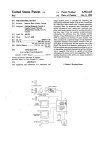
Fig. 1. Model 12050A Fiber Optic
HP-IB Link can transfer data over
the HP Interface Bus (compatible
with ANSI /IEEE 488-1978) at 20
kilobytes per second. It performs
error detection and automatic re
transmission, and has powerful in
ternal and link testing capabilities.
DECEMBER 1979 HEWLETT-PACKARD JOURNAL 3
© Copr. 1949-1998 Hewlett-Packard Co.
of an instrumentation cluster in a production environ
ment, and demonstrates the ease of duplicating the test
set-up while maintaining the advantages of single-com
puter control.
HP 1000
Computer or
HP 9800 Series
Desktop Computer
Established Technologies Used
HP 12050A
Fiber Optic
HP-IB Link
NoiseImmune
Fiber Optic
Cable
HP 2240A
Measurement and
Control Processor
II II II II II I
Application
(Measurement and Control Signals
to/from Sensors, Switches, Equipment, etc.)
A key objective for the development of the 12050A was to
use existing hardware and technologies, with an emphasis
on HP fiber optic transmitter/receiver pairs and SOS
(silicon-on-sapphire) components. These parts provide the
high speed and low power consumption that allow the
12050A to achieve real-time operation without overly com
plex design. In this way, development emphasis could be
concentrated on how to make the interface truly behave like
a standard HP-IB cable instead of wasting efforts on a broad
range of hardware trade-offs.
Centering the design approach around a high-speed SOS
microprocessor (see Fig. 4) provides a great deal of flexibil
ity, but at the same time limits the speed of the link. The
design center definition of "real-time", however, must rec
ognize the capabilities of today's computers and instrumen
tation. Few instruments are capable of approaching the
one-megabyte-per-second theoretical rate of the HP-IB, and
Fig. 2. In a typical application, a 12050 'A connects a comput
er to a group of HP-IB instruments up to 100 metres away. The
fiber optic cable is immune to electrical noise and lightning,
provides electrical isolation for rejection of common mode
signals such as ground potential differences, is safe in explo
sive environments, and can reduce installation costs by
eliminating the need for special protective equipment or
shielding.
completely immune to this interference, which plays havoc
with also electrical signals. Fiber optic transmission also
provides isolation to prevent common-mode voltage prob
lems, and is safe in explosive environments.
The 12050A emphasizes real-time operation by continu
ously transmitting data at over 20 kilobytes per second and
by asserting each service request (SRQ) at the computer end
of the link within 100 microseconds of its occurrence at the
remote end. Serial communications are performed at one
megabit per second for data and protocol support, and at ten
megabits per second for special messages. These specifica
tions ensure that most HP-IB systems perform just as they
do when connected in strictly local configurations.
The 12050A detects any errors in transmission from one
end of the link to the other and automatically retransmits
the data until it is received correctly. At a continuous rate of
1 Mbit/second, over 109bits/hour can be transmitted. Most
fiber optic parts have specified reliabilities in the range of 1
error in 109 transmissions. Thus it is important that the
12050A perform automatic error correction, even though
the probability of any errors is very small, since many con
trol applications run twenty-four hours a day.
The use of the 12050A Fiber-Optic Link is illustrated in
Fig. 2. One unit is connected to the local computer's HP-IB
port and another is connected remotely to an instrumenta
tion application. No special programming is necessary to
use the 12050A. This is particularly important to many
existing applications. Fig. 3 characterizes the typical use
4 HEWLETT-PACKARD JOURNAL DECEMBER 1979
© Copr. 1949-1998 Hewlett-Packard Co.
Remote Instrumentation
Computer and
Local Instrumentation
Fig. 3. The fiber optic link makes it easy to duplicate a group
of HP-IB instruments at several sites, using a single computer
at one site (many production test stations are in this category).
A Ready-to-Use Fiber-Optic Link for
Data Communications
by Delon C. Hanson
During this past year there has been a significant growth in interest
in adapting fiber-optic data links to a broad spectrum of applications
ranging from local data communications to long-distance telephone
communications. This heightened interest results from the advan
tages that optical fibers have over metallic conductors for transmit
ting but The advantages depend on the application but
include the following:
• Immunity from electromagnetic interference
• No electromagnetic emission
• Freedom from ground loops
• Smaller cable size and weight
• Higher bandwidth
• Longer link length without repeaters
• Potentially lower cost in volume production.
Interest within Hewlett-Packard in exploring the potential of fiber
optics HP to establishment of a program several years ago in the HP
corporate research laboratories that focused on the requirements for
local in communications between computers, terminals, and in
struments. Since practical fiber-optic components for these applica
tions did not exist at the time, a system analysis was initiated to
specify the functional features of a suitable link and the optimum
balance of performance parameters for individual link components.
A basic requirement was that the fiber-optic data link must behave
like a TTL gate as far as signal inputs and outputs are concerned. The
user would thus not need any special optical expertise. This implies
that the transmit/receive modules must accommodate:
• Arbitrary data formats
• Data rates from dc to a specified maximum
• Operation from a single +5V supply
• Monitoring of the link's function.
Adaptable Coding
The requirement for transmission down to zero hertz with arbitrary
data in cannot be implemented in fiber optics as simply as in wire
links zero the use of opposite polarity pulses can establish a zero
average dc level (photons do not have a negative state). Con
sequently, an internally-generated code, called pulse bipolar with
refresh, was developed.
The bipolar code is a translation from a two-level electrical signal to
a three-level optical signal (Fig. 1). A mid-level luminance flux is
established as the average dc level. For a link specified to transmit
data pulses with a minimum width of 1 00 ns, each positive-going data
transition, such as the leading edge of a data pulse, generates a
positive 60-ns optical pulse (maximum luminance) and each
Code
Fig.1.
-60ns
0 %
negative-going data transition, such as a pulse's trailing edge, gen
erates a negative 60-ns pulse (no luminance).
Whenever the time between data transitions exceeds about 5 ¿is, a
refresh pulse of the same polarity as the previous pulse is generated
and is polarity every 5 ¿is until a data pulse of the opposite polarity
occurs. The refresh pulses provide transparent signal continuity in
dependent of the data stream for maintaining ALC (automatic level
control) action at the receiver and for use in monitoring the status of
the link.
Transmitter Module
The transmitter uses an LED optical source driven by two current
sources: one that is normally on and one that is normally off. The
normally-off source is controlled by a gate that is turned on by a
positive step in the data stream and off about 60 ns later by an
inverted and delayed version of the same step. Similarly, the
normally-on current source is turned off by a gate in response to a
negative step and on again about 60 ns later in response to an
inverted and delayed version of the step.
The refresh circuit consists of a retriggerable monostable multivi
brator data has a period of about 5 ¿is. It is triggered on by either data
transition. In the absence of a data transition during the refresh
period, it resets and the resulting transition is steered to the appro
priate optical pulse generating circuits by gates controlled by the
data to The transition also triggers the multivibrator to start a new
refresh cycle.
All of the transmitter circuits have been designed into a single
integrated circuit housed in a low-profile module that is physically
compatible with conventional dual in-line 1C packages and that can
be mounted directly on printed-circuit boards.
Receiver Module
The receiver uses a reverse-biased PIN diode as the detector. The
diode current is proportional to the received optical power. The peak
value of this current can be between 100 nA and 50 /uA depending
Delon C. Hanson
Del Hanson earned a BSEE degree
from the University of Wisconsin (1 959),
an MEE degree from New York Univer
sity (1961), an MS degree in physics
(1966) and PhDEE (1967) from the Uni
versity of Michigan, and an MBA de
gree from Golden Gate University
(1978). From 1959 to 1964 he was with
Bell Telephone Labs and from 1964 to
1967 he was associated with the Elec
tron Physics Lab at the Univerity of
Michigan. He joined HP in 1967, initially
working on solid-state microwave oscil
lators. He currently is fiber optic R and
D section manager at HP's Optoelec
tronics Division. Del is an A.Y.S.O. soccer referee and a memberowner of a 5000-acre recreational ranch in northern California where
he vacations with his wife and three children (10, 13, 16 years)
camping, horse-back riding, hunting, fishing and skiing.
DECEMBER 1979 HEWLETT-PACKARD JOURNAL 5
© Copr. 1949-1998 Hewlett-Packard Co.
on link length, so ALC is used to force the height of the input
amplifier's output pulse to be constant under all conditions. This also
improves the signal-to-nolse ratio under higher drive conditions. Be
cause circuit the inclusion of the ALC circuits, no adjustments to the circuit
are needed for normal operation.
The ALC voltage also provides a monitor, available at one of the
receiver module's output pins, of the presence or absence of an
optical input signal.
Comparators with threshold levels at the 25% and 75% points of the
bipolar waveform determine whether a data pulse Is present and
whether It Is negative- or positive-going. The positive comparator
output sets an RS flip-flop and the negative comparator resets it,
regenerating the original two-level data waveform.
The receiver circuits are designed into an Integrated circuit that Is
housed in a module similar to that used for the transmitter.
Connectors and Cable
Precision single-fiber connectors with a small diameter were de
veloped for inclusion as Integral parts of the module and as cable-
even fewer computers begin responding to real-time situa
tions in less than one millisecond. So speeds of 20,000 bytes
per second and above are quite adequate for most of today's
instrumentation systems, and the ease of developmental
changes offered by a microprocessor design was a signifi
cant advantage.
to-cable Interconnects. Also developed was a rugged fiber optic
cable specifically optimized for local data communications. It has a
100-¿¿m-d¡ameter fused silica core with a glass cladding that is
protected by a thin silicone coating between the fiber and a buffer
jacket. The buffer jacket is surrounded by strength members and a
polyurethane outer jacket to provide a rugged, single-fiber-perchannel cable assembly.
Acknowledgments
Paul Greene, Tom Hornak, and Bill Brown of HP's Solid-State
Research Laboratory were instrumental In the conceptual and pro
totype phases of this development program. Roland Haitz, George
Girot, Steven Garvey, Lee Rhodes, Joe Bagley, and Hans Sorensen
of HP's dur Division made substantial contributions dur
ing final development. Personnel at HP's Santa Clara Division coop
erated on the development of and processing for the receiver Inte
grated circuit and many others, unfortunately too many to be men
tioned here, made significant contributions to the development
program.
A simplified picture of the logic flow controlling the
movement of data across the 12050 A Fiber Optic Link is
illustrated in Fig. 5. There are four key operations:
Read HP-IB Data
Format and Transmit the Data
Receive and Verify the Data
Write HP-IB Data
Determining the Critical Timing Paths
There is a complete spectrum of trade-offs between the
design that performs the maximum number of logic deci
sions using a microprocessor and the design that com
pletely eliminates the microprocessor and implements all
the logic in hardware alone. The key to a successful
microprocessor-based design that maximizes throughput is
to implement in hardware those logic decisions that fall
into the critical timing paths.
Remote 12050 A
Local 12050A
Fiber optic transmitter/receiver
pair used with up to 100 metres
of duplex cable to transmit and
receive data and control signals.
PHI (Processor to
HP-IB) chip. Pro
vides the interface
between MC! and
the HP-IB. It is
capable of all
HP-IB controller
and talker/listener
functions.
MC2 (MicroComputer Chip)
is a 16-bit micro
processor oper
ated at a 5-MHz
clock rate. It is op
timized for effi
cient operations
performed directly
on I/O registers.
USART (universal
synchronous/
asynchronous
receiver/transmitter
provides the inter
face between the
MC! and the fiber
optic components.
It transmits
and receives data
asynchronously at
1 M Bits.
Mark
Byte As
Retransmit
Transmit
Optic
Bytes
No
2K x 16 bits of
ROM contains all
of the firmware
logic necessary to
perform self-test
and ali operations.
Fig. 4. The fiber optic link has a single printed circuit board
with a combination of advanced technologies.
6 HEWLETT-PACKARD JOURNAL DECEMBER 1979
© Copr. 1949-1998 Hewlett-Packard Co.
Correct
Receipt
Acknowl
edged?
Yes
Fig. of Simplified flow of HP-IB data in the 12050A. Receipt of
each byte is acknowledged by a handshake to the opposite
12050 A.
The microprocessor adds a fifth component because the
very process of determining which operation to perform
takes time. Each of these operations has special hardware
logic to minimize the overall time necessary for the entire
operation. For example, the receive and verify function is
supplemented with two special circuits shown in Fig. 6.
The error control circuit verifies correct receipt of the HP-IB
byte. Each byte is accompanied by a second byte composed
of two bits of control information and six bits of checksum
information. This checksum is compared in hardware so
that the process of reading the HP-IB byte from the USART
(universal synchronous/asynchronous receiver/transmitter)
is accompanied by a go/no-go flag. The link command cir
cuits then ensure that acknowledgment of correct receipt of
the data is sent in the minimum amount of time to the
opposite 12050A. This is done by sending a short burst of
pulses at 10 Mbits/second that can be distinguished from
normal data by special circuitry. Acknowledgment of HP-IB
data on a byte-by-byte basis in this way minimizes the
overhead involved in data buffering, and helps to ensure
real-time responses to asynchronous messages.
By consciously restricting supplemental circuitry to the
critical timing sequences, a secondary design goal was
achieved. This was to minimize package size and power
consumption. Thus overall cost is minimized through re
duced power supply complexity, while reliability is in
creased. The calculated mean time between failures
(MTBF) for the 12050A is greater than 30,000 hours of
operation, an important factor in manufacturing applica
tions. At the same time, the emitted radiation of the 12050A
is extremely low, making it a good fit for HP-IB systems
concerned with measuring electromagnetic interference
(EMI). In actual tests using a 12050A and a 2240A Mea
surement and Control Processor, the combination of the two
instruments was at least 10 dB below the VDE level B
requirements for emissions from industrial instrumenta
tion.
System-Level Capabilities
The fiber optic link, like any other HP-IB device, is as
signed its own address and can communicate with the
computer. Four powerful system-level requests from the
computer to the 12050A are used to determine the general
status of the link automatically (Fig. 7). Self-test (S) causes
execution of a series of routines contained in the ROM of
each individual unit. These routines exercise off-line all of
the control logic and circuitry used during normal opera
tion. A failure in any of these tests is indicated by a pattern
in the front-panel lights, and indicates that the link cannot
operate. This test can also be manually initiated via the reset
switch on the 12050A rear panel.
Link test (L) examines the integrity of the complete twopair link by initiating the transfer of all possible eight-bit
ASCII combinations from the local to the remote end. The
same patterns are then transferred back from the remote end
to the local. During the test all checksum errors are counted,
and the local 12050A can be interrogated to determine the
results. Extended link test (E) performs the same function as
link test 256 times, and the total error counts can be checked
as in the link test.
Counting of checksum errors is not restricted to the selftests. At any convenient time during normal operation,
Link Monitor
Interrupt
Microprocessor
(MCC)
Address Bus
Data Bus
IFC, REN
Random-Access
Memory
(RAM)
Read-Only
Memory
(ROM)
SRO, EOI
ATN, Special
Handling
I
Front Panel Lights
Command
HP-IB-
Parallel
Data.
Universal
Synchronous/
Asynchronous
Receiver
Transmitter (USART)
Serial
Data
Data and
Link Command
Separator
Optic
Receiver
Link Command
Transmitter
Optic
Transmitter
Optic Link
Serial Data
Command
Optic
Link
Fig. supplemented logic 12050A block diagram. LSI functions are supplemented by discrete logic to
maximize speed.
DECEMBER 1979 HEWLETT-PACKARD JOURNAL 7
© Copr. 1949-1998 Hewlett-Packard Co.
DIAGNOSTIC REQUESTS
S - Execute self-test at local
and remote link units.
L - Execute link test to verify correct
operation of complete 12050A to
12050A link.
E - Execute extended link test (link
test executed 256 times).
D - Down the link. Both local and remote
12050 As are set off-line and do not
interfere with any HP-IB transactions
until IFC message is received via
local HP-IB.
Fig. 7. Four system-level requests from the computer to the
72050/4 are used to determine the general status of the link.
The down-link command has many uses.
The fourth system-level request, down link (D), is a useful
tool in certain applications where it is advantageous tem
porarily to cease communications with remote HP-IB de
vices. The simplest case is when HP-IB data transfers faster
than 20,000 bytes per second are desired at the local end of a
link. Normally the data transfer can occur only at the rate of
the slowest device on the bus, which in this case is the local
12050A. When the down link request is given before the
higher-speed transfer, the local 12050A completely ignores
the transaction.
Another use of the down link command is illustrated in
Fig. 3. Where a group of instruments is identical to another
group, even down to the individual HP-IB addresses, the
two groups can be accessed alternately via two fiber optic
links by alternately setting the links off-line.
Compatibility Testing
these local and remote checksum error counts can be read to
ensure that no partial degradation of the link has occurred.
Each time the error counts are read, they are reset to zero.
Besides monitoring integrity by counting checksum er
rors, the firmware attempts to report the cause of any ir
recoverable error in the link. For example, when a link
monitor error (generated by the fiber optic receiver module
whenever the received light level falls below the minimum
acceptable level) is detected by one of the 12050As, it
causes a continuous flashing pattern in the front-panel
lights.
The extensive use of HP-IB systems throughout HP pro
vided an opportunity to characterize the performance of
instrumentation systems interfaced via the 12050A Fiber
Optic Link, and to ensure operation with a broad spectrum
of applications. Tests were run at seven different HP divi
sions using demonstration programs, production test pro
grams, lab development programs, and programs specifi
cally developed for verifying HP-IB compatibility of other
instruments. Over fifty different HP-IB compatible devices
were used in one or more of the systems exercised. The
performance of the 12050A during these tests has led to a
Fig. 8. Fiber optic link applica
tions within HP. (a) The 12050A is
used to reduce electrical noise in
the vicinity of HP-IB instruments
under test during screen room and
RFI tests, (b) Numerous 12050As
provide lab engineers with conve
nient printed hardcopy and
graphics capabilities at or near
their own desks, (c) A 2240A
Measurement and Control Pro
cessor is used to control a metalsputtering system in the produc
tion ofsilicon-on-sapphire circuits.
Use of the 12050A allows the
computer to be removed from the
clean room environment for easy
user access, while maintaining
real-time processing capabil
ities, (d) One pair of 12050AS
connects an HP WOO computer to
a process control simulation in a
demonstration room. Another pair
of 12050As connects an HP 1000
in the same room to HP-IB in
strumentation in various class
rooms.
8 HEWLETT-PACKARD JOURNAL DECEMBER 1979
© Copr. 1949-1998 Hewlett-Packard Co.
large number of HP applications, some of which are shown
in Fig. 8.
At the same time, it was clear that many disc devices that
are interfaced via the HP-IB use one feature of the HP-IB,
parallel poll, that is not supported by the serially oriented
12050A. If those devices were to be used with the 12050A,
their responses would have to be determined with the
HP-IB serial poll feature.
Acknowledgments
I want to express particular appreciation to Dick Cook,
who was responsible for the complete hardware design of
the 12050A and who helped investigate and categorize the
wide variety of bus conditions we saw during the course of
the project. Dave Hannebrink and Bill Dwyer also played
key roles in maintaining project momentum and en
thusiasm. Brice Clark helped provide project resources,
King-Wah Yeung designed the power supply, Dennis
Mitchell designed the 12050A package, and Steve Joseph
aided with the firmware. Thanks to the many others who
provided us support throughout the project. Special thanks
to Virgil Laing, Geoff Chance, Dave Smith, Charlie Martin,
Nick Kuhn, Don Mathiesen, Rich Irwin, Joe Williams and
Allert Ligtenberg at other HP divisions for their support of
our compatibility testing.
Reference
1. Foreword to IEEE Std 488-1978, "IEEE Standard Digital
Interface for Programmable Instrumentation."
Robert B. Grady
Bob Grady, project manager and
firmware designer for the 12050A,
celebrates his tenth year with HP this
month. In those ten years, he has man
aged development of the 2240A Mea
surement and Control Processor
hardware, the HP ATLAS Compiler,
software for automatic instrument cali• bration, and systems self-test. A native
I ^fl I of Chicago, Illinois, Bob received his
BSEE degree from Massachusetts Insti
tute of Technology in 1965 and his
MSEE degree from Stanford University
in 1969. He and his wife, who is a
I programmer/analyst at HP, have a son
and a daughter and live in Los Altos, California. Bob plays basketball
and Softball in local city recreation leagues and enjoys mountain
vacations — hiking, camping or skiing.
SPECIFICATIONS
HP Model 12050A Fiber Optic HP-IB Link Units
39200 Series Fiber Optic Cable
HP-IB DATA RATE: 20.000 bytes/s maximum between 12050A units assuming continu
ous data of Overall system performance is subject to HP-IB handshake rates of
devices over to the 1 2050As, the composition of commands and data being sent over
the link, and the rate of transmitted errors between 12050A units. Typically the error rate
between 12050A units will be low due to the highly secure fiber optic cable transmission
medium and in most cases, will not affect system performance.
SERVICE REQUEST RESPONSE: Remote device service request (SRQ) asserted at local
end of link typically within 100 us of its occurrence.
ERROR DETECTION AND CORRECTION: Detection of transmitted errors between 12050A
units is done using a checksum byte comparison technique. If an error is detected,
retransmission of the byte will occur until it is correctly received.
CONFIGURATION CAPACITY: Each 12050A unit is treated as an HP-IB device and
is subject to HP-IB cabling and configuration restrictions imposed by the interface
standard.
CONNECTORS: HP-IB connector is the standard IEEE 488-1978 24-pin female connector
for use precision HP 10631 A/B/C/D HP-IB cables. Fiber optic connectors are precision ferrule
optical Cable for use with 39200 Series Fiber Optic Cables (see Fiber Optic Cable
specifications).
HP-IB RL1, SUBSETS SUPPORTED: SH1, AH1. T5. TE5. L3. LE3, SR1, RL1, PPO,
DC1 , poll not C1 , C2, C3. C4, C27. Controller functions parallel poll and pass control are not
supported. (Refer to IEEE Std. 488-1978.)
OVERALL SYSTEM COMPATIBILITY: The HP 12050A Fiber Optic HP-IB Link has been
designed to allow HP-IB devices to communicate with each other over long distances just
as they would locally using standard HP-IB programming techniques and conventions.
Extensive testing has been performed using a wide variety of HP-IB compatible instru
ments to ensure such operation.
POWER REQUIREMENTS:
VOLTAGE (ac single-phase): 86V to 127V; 172V to 254V.
FREQUENCY: 48 Hz to 66 Hz.
POWER CONSUMPTION: 15W.
OPERATING TEMPERATURE: 0 to 55°C.
HUMIDITY: 10 to 95% relative humidity non-condensing at 40°C.
PHYSICAL DIMENSIONS:
HEIGHT: 9 cm (3.5 in).
WIDTH: 21 cm (8.4 in).
DEPTH: 44cm (17.4 in).
WEIGHT: 2.75 kg (6 Ib 1 oz).
OPERATING TEMPERATURE: 0 to 70CC.
STORAGE TEMPERATURE: -40 to 85°C.
RELATIVE HUMIDITY: 95% at 70 C.
MAXIMUM TENSILE FORCE ON CABLE: 30 kg (66 Ib) per channel
MAXIMUM TENSILE FORCE ON CONNECTOR/CABLE: 5 kg (11 Ib).
MINIMUM BEND RADIUS: 7 mm (0.3 in).
FLEXING: 50000 cycles (180° bending at minimum bend radius).
CRUSH LOAD: 20 kg (44 Ib).
CABLE CONSTRUCTION: Simplex (one-channel) and duplex (two-channel) cable, connectorized glass each end. Each channel consists of a fused silica, slightly graded index, glass
clad fiber (140 /¿m diameter) surrounded by silicone coating, buffer jacket and tensile
strength members. Outer jacket is polyurethane. The two channels of the duplex cable are
connected by an easily separated zip cord structure which also provides channel identity by
an extruded ridge on one side.
WEIGHT: 12 grams (0.43 oz) per metre - simplex
24 grams (0.85 oz) per metre - duplex
Ordering Information
HP 12050A FIBER OPTIC HP-IB LINK unit (includes installation and Service Manual
1 2050-90001 ). Two 1 2050A units are required per remote application. Each pair of 12050A
units 39200 one or two of the following fiber optic cable products. All 39200 Series cables
are supplied with preassembled and pretested fiber optic connectors.
Only Cable cable length may be used to connect the 1 2050A units. Cable to cable interconnec
tions are not permitted.
PRICE IN U.S.A.: 12050A, $1950 each unit (two required per remote site).
MANUFACTURING DIVISION: DATA SYSTEMS DIVISION
1 1000 Wolfe Road
Cupertino, California 94014 U.S.A.
DECEMBER 1979 HEWLFTT-PACKARD JOURNAL 9
© Copr. 1949-1998 Hewlett-Packard Co.
A Picoammeter with Built-in, Synchronized
Voltage Sources
This new digital picoammeter makes measurements of
small current with a resolution of 10~15 amperes, and it
provides programmable voltage steps and measurement
delays for automatic I-V measurements on semiconductors,
insulation materials, capacitors, printed-circuit boards, and
other components.
by Hitoshi Noguchi
CONTINUING ADVANCES in technology have in
tensified the need for high-performance picoammeters to measure very small currents. These
measurements are needed not only for evaluation of elec
tronic components and electric materials, but also for the
detection of physical and chemical phenomena. Many of
these measurements also require adjustable voltage
sources so current can be determined as a function of the
applied voltage.
The new Model 4140A pA Meter/Dc Voltage Source was
developed in response to these needs. It includes a sensitive
picoammeter and two voltage sources, all managed by a
microprocessor. One of the voltage sources can be pro
grammed to step through a range of values and to hold at
each step while the current is measured. The other voltage
source provides a fixed bias for measurements on devices
such as transistors where two bias voltages are required.
Previously, measurements of this nature were made with
manually controlled instruments, consuming much time,
or with automatic test systems that cost at least three or four
times as much as the 4140A, in addition to requiring pro
gramming expertise.
The 4140A can also be programmed to supply a ramp
voltage to the device under test for quasi-static capacitance-versus-voltage measurements, a technique that is
especially applicable to measurements on MOS capacitors.
High Resolution with Stability
The pA meter in the 4140A is a floating, autoranging
picoammeter that has full-scale ranges from ±1 p A to ±10
L O G
É' @ GCG
G
0
D O G
I r DO POD O
10 HEWLETT-PACKARD JOURNAL DECEMBER 1979
© Copr. 1949-1998 Hewlett-Packard Co.
G C
Fig . 1 . Model 41 40ApA Meter/Dc
Voltage Source makes stable
picoampere measurements with a
maximum resolution 7 x JO"'
amperes. Two programmable vol
tage sources, one oÃ- which can
step or sweep through a selected
range, are provided for biasing the
device under test. This instrument
can also measure capacitances in
a range of 0. 1 to 1900 pF.
10ms (50 Hz)
8.3 ms (60 Hz)
Measurements
mA(±lxlO Vi to ±1X10 ^ amperes). The 3V2-digit read
out gives a resolution of 1 femtoampere (10~15 A) on the
most sensitive range. A zero offset cancels leakage currents
in the test leads or fixtures of up to 100xlO~15 amperes.
Measurement data is stabilized by digital averaging. To
accommodate changing values, a moving average of the
readings is kept with the oldest reading discarded when a
new one is added (Fig. 2). The number of readings averaged
(integration time] is selectable (short, medium, long) ac
cording to the desired meter response or expected mea
surement fluctuations. These times are automatically ex
tended on the more sensitive ranges and shortened on the
higher ranges to maintain the fastest response consistent
with the measurement noise.
Automatic Voltage Control
Each of the two programmable voltage sources spans
±100 V in two ranges (±10. 00V, ±100. 0V) and is capable of
supplying up to 10 mA. Individually selectable current
limits of 10~4,10~3, or 10~2 amperes protect sensitive
devices.
The ramp voltage provided by one of the sources is used
for measurements of capacitance based on the relationship:
C=
I
dV/dt
farads.
For example, if the ramp rate, dV/dt, is 0.01 V/s and the
measured current is 1.234xiO~12A,
C=
1.234X10"12
= 123.4 pF.
0.01
The details of the ramp are shown in Fig. 3a. The ramp
slope is selectable from ±1 mV/s to ±1 V/s in 1-mV/s steps.
The average ramp voltage during each measurement is dis
played along with the current or capacitance data.
The details of the staircase voltage, used mainly for I-V
Fig. 2. Measurement fluctuations
are smoothed by digitally averag
ing several readings. As each new
measurement value is added, the
oldest value is subtracted to main
tain a running average.
characterization, are shown in Fig. 3b. The voltage can be
stepped in increments selectable with 0.01V or 0. IV resolu
tion depending on the voltage range. The hold time is
selected to allow time for the device or material under test to
settle at the new voltage. The measurement time is deter
mined by the selected integration time for the picoammeter.
Low-Leakage Accessories
Great care must be exercised when connecting a
picoammeter to a device for very-low-current measure
ments because leakage currents can degrade the measure
ment significantly. A set of cables (Fig. 4) is provided with
the 4140A to minimize inaccuracies due to leakage. The
cable for the current input is a low-noise triaxial cable that
helps minimize leakage currents. Also available is an acces
sory test fixture (Fig. 5) that provides both electrostatic and
light shielding for the device under test.
An option equips the 4140A to work with the HP Interface
Bus so that all front-panel controls can be programmed
remotely. With this option, measurement data can be sent to
a controller for processing and then displayed in a variety of
formats, an especially useful capability in a manufacturing
environment where rapid feedback is desirable. Another
option provides analog signals for driving an X-Y recorder.
Examples of the measurements that can be made with the
4140A are shown in Fig. 6. Fig. 6a is a typical C-V measure
ment plotted by a Model 9872A Digital Plotter under con
trol of a Model 9825A Desktop Computer that also controls
the 4140A through the HP-Interface Bus. Fig. 6b is an I-V
measurement. Since the current varies over a wide range in
this measurement, the autoranging feature of the 4140A
proves to be especially useful. Fig. 6c is a plot of an I-V
measurement in which both voltage sources are varied
under program control.
Internal Details
A simplified block diagram of Model 4140A is shown in
•Hewlett-Packard's implementation of ANSI-IEEE 488/1978.
Stop V
Start V
(b)
Time
Fig. 3. (a) Details of the ramp volt
age. The start and stop voltages,
hold time, and ramp slope are
selectable. Themeasurementtime
is determined .¡y the picoammeter
circuits, (b) Db.a/'/s of the staircase
voltage.
DECEMBER 1 979 HEWLETT-PACKARD JOURNAL 1 1
© Copr. 1949-1998 Hewlett-Packard Co.
•n
Fig. 4. Fesf /eacte provided with the instrument include a
low-noise triaxial cable for the current to be measured. A
mounting plate for the user's test fixture is also provided.
Fig. light Accessory test fixture provides electrostatic and light
shielding for the device under test. One connection plate is
provided for use with the clip leads (included) and a second
plate is provided for TO-5 type sockets.
MOS C-V CHARACTERISTICS HP <UBy/an?s«/M7!»
SAMPLF>CM4K3-12 #6 0/10/79
[/\\
If,
VA
MCJS FET CHARACTERISTICS Hnniw/98H«/9872«
SUBTHRESHOLD
SAMPLE = CM4K3-12 45 P-CH lB0/ln0 9/10/79
vv
I-V CHARACTERISTICS up wi<
GATE CONTROLLED DIODE
:129-2B 8/10/79
Fig. 6. Typical measurements on
semiconductors made with Model
4140A.
12 HEWLETT-PACKARD JOURNAL DECEMBER 1979
© Copr. 1949-1998 Hewlett-Packard Co.
. pA Section
Front-Panel
Control &
Display
Fig. 7. Simplified block diagram
of Model 4140A. All the analog
controls and the data processing
are managed by the microproces
sor, an M6800.
Fig. 7. A current-to-voltage converter at the input generates
a voltage proportional to the measured current for proces
sing by conventional digital voltmeter circuits (in this case,
a successive approximation A-to-D converter to achieve
measurement speed). The basic I-to-V converter circuit, a
type widely used in electronic pico-, micro-, and milliarnmeters, is shown in Fig. 8. In this circuit, all of the input
current flows through range resistor RR while negative
feedback keeps the amplifier input near zero. The
amplifier's output impedance is low enough to drive suc
ceeding circuits without disturbing the input source.
RR
icon 100GU
-w\—
-04!
J
/I Voltmeter
LO O
W
Fig. to Basic current-to-voltage converter uses feedback to
maintain the input voltage near zero while the unknown current
develops a measurable voltage across range resistor RR.
Successful application of this circuit to a picoammeter
requires exceptionally high amplifier input impedance and
low offset. Since gain in an amplifier can be controlled
precisely by generous amounts of negative feedback
whereas dc offsets are not so easily controlled, it is common
practice to convert a low-level dc input to an ac whose
peak-to-peak excursions are proportional to the dc. After
amplification to a level where offsets become insignificant,
the ac is converted back to dc.
This technique is realized in the 4140A by the amplifier
circuit diagrammed in Fig. 9. The voltage-variable capaci
tances, Cvl and Cv2 — actually the gate capacitances of a
dual-junction FET — and the center-tapped secondary of
transformer Tl form a bridge, driven by a 500-kHz, 20-mV
signal. The bridge is balanced when there is no input to the
HI/LO terminals but when a dc voltage Vin appears at the
input, one capacitance increases and the other decreases so
the bridge becomes unbalanced. An ac voltage V2 then
appears at the input to amplifier Al. This voltage is
amplified in Al, reconverted to dc by the synchronous
detector, and smoothed in integrator A2. Total gain from
input to output (Vin to V0) is more than 100 dB.
Note that there is no dc path in the input circuit. This plus
careful layout of the circuits surrounding the FETs achieves
input bias currents of typically less than 3 t'A and output
Integrator
Fig. 9. The input amplifier used in
the 41 40 A has a high dc input im
pedance since there is no dc path
in the input circuit. In the absence
of an input, the bridge formed by
transformer J1 and capacitances
Cv , and Cv2 is balanced. An input
voltage unbalances Cv! and Cv2
differentially and an ac voltage,
V2, then appears at the input to
amplifier A 1 .
DECEMBER 19/9 HEWLETT-PACKARD JOURNAL 13
© Copr. 1949-1998 Hewlett-Packard Co.
10 x 10~15 (A)
Fig. 10. Recording demonstrates
the stability of the 4140A on its
most sensitive range. For this test,
the source resistance was 100 Gil
and the measurement integration
time was set to LONG.
^
30 minutes-
solution to this problem, often used in digital voltmeters, is
to use an autozero operation. The autozero operation dis
connects the input signal, grounds the amplifier input, and
closes a negative feedback loop around the amplifier to a
holding capacitor at the amplifier's inverting input. If the
amplifier has an offset at the instant the switching takes
place, the offset would start to charge the holding capacitor
in the same direction as the offset, but since the capacitor
voltage is applied to the amplifier's inverting input, the
capacitor voltage tends to counteract the offset. As a result,
the offset is reduced by a factor proportional to amplifier
gain. The feedback loop is then opened and the offset cor
rection voltage is retained on the capacitor.
To keep offset drift at negligible levels, an autozero opera
tion should be performed at least once every 10 seconds.
Since ramps generated by the 4140A may last hundreds of
seconds, the ramp generator was designed to permit autozeroing at 10-second intervals without creating any discon
tinuities in the ramp. As shown in Fig. 12, the autozero
operation is performed on main amplifier Al and the offset
correction voltage is retained on holding capacitor CHI- A
local integrator, A2, within the main integrator loop dupli
cates the ramp in response to the voltage that the main
feedback loop places on holding capacitor C^- While the
autozero operation is being performed with the main feed
back loop open, A2 continues ramp generation in response
to the voltage held on C^2. Hence, no discontinuities are
introduced into the ramp.
The overall amplification provided by Al and A2 in cas
cade provides extremely high open-loop gain, minimizing
any nonlinearity in the ramp.
offsets of less than 10 ^iV/°C at room temperatures. The
feedback through range resistor RR, however, makes the
circuit input impedance appear low to the device under
test. Fig. 10 shows the output stability when the instrument
is on the most sensitive range and Fig. 11 shows the step
response on the same range.
The front-panel zero offset is implemented digitally.
When the ZERO button is pressed while the device under
test is not connected, the displayed value of leakage cur
rent, or stray capacitance in the case of C-V measurements,
is stored. This value is then subtracted from subsequent
measurements.
+ 1 x 1(T12(A)
-1 x i<r12 (A)
Fig. 11. Step response of the Model 41 40 A, under the same
conditions as the recording of Fig. 10, shows an absence of
overshoot and other ambiguities. Similar clean response is
obtained with the integration time set to MED and SHORT.
Voltage Sources
The voltage sources are essentially stable power
amplifiers driven by a digital-to-analog converter (DAC).
Sample-and-hold techniques enable a single 12-bit DAC to
drive both outputs and generate the stepped voltages.
Ramps are generated by an integrator in response to a step
supplied by the DAC (Fig. 12). Ordinarily, the linearity of
slow ramps is degraded by temperature variations that
cause One voltage drift in the integrator's amplifier. One
Ramp Rate
Data.
Acknowledgments
Yoshihisa Kameoka, who was the project leader during
the early stages, was responsible for the pA section. Keiki
Kanafuji also contributed to the pA section design. Susumu
CM
0.33/tF
RM
20.8MÃ1
CI2
0.33fiF
R|2
Autozero
Switch
10MÃ1
Out
^>T
-X-
•?
Main Amplifier
3
CH2
Local Integrator
14 HEWLETT-PACKARD JOURNAL DECEMBER 1979
© Copr. 1949-1998 Hewlett-Packard Co.
Fig. 12. Ramp generator under
goes autozero operations for the
main amplifier without disturbing
the ramp in progress.
no
HEWLETT-PACKARDJOURNAL
Volume 30 January 1979 through December 1979
Hewlett-Packard Company, 1501 Page Mill Road, Pato Alto, California 94304 U.S.A.
Hewlett-Packard Central Mailing Department, Van Heuven Goedhartlaan 121, 1180 AM Amstelveen. The Netherlands
Yokogawa-Hewlett-Packard Ltd., Sugmami-ku, Tokyo 168 Japan
PART 1: Chronological Index
January 1979
A Low-Cost, Microprocessor-Based 100-MHz Universal Counter,
Lewis W. Masters, Karl M. BJankenship, and Michael /. Ward
Lowest-Cost HP Universal Counter Developed Using LSI and
Manufacturing Innovations, Michael D. Wilson and David M.
George
A High-Performance Bipolar LSI Counter Chip Using EFL and
PL Circuits, Bosco W. Wong and William D. Jackson
A Synthesized Signal Source with Function Generator Capabil
ities, Dan D. Danielson and Stanley E. Froseth
Viewpoints — Paul Baird on Electronic Equipment Reliability
February 1979
A High-Quality Digital X-Y Plotter Designed for Reliability, Flexi
bility and Low Cost, John A. Fenoglio, Bessie W.C. Chin, and
Terry R. Cobb
Linear Step Motor Design Provides High Plotter Performance at
Low Cost, Lung-Wen Tsai and Robert L. Ciardella
Developing a Low-Cost Electrostatic Chart-Hold Table, Alec J.
Babiarz
Simple, Efficient Electronics for a Low-Cost X-Y Plotter, William
G. Royce and Peter Chu
A Closed-Loop System for Smoothing and Matching Step Motor
Responses, Philip P. Maiorca and Norman H. MacNeil
Multi-Frequency LCR Meters Test Components under Realistic
Conditions, Kohichi Maeda and Yoh Narimatsu
March 1979
Circuit-Board Testing: Cost Effective Production Test and Trouble
shooting, Peter S. Stone and John F. McDermid
Rapid Digital Fault Isolation with i ASTRACK, William A. Groves
Software Simulator Speeds Digital Board Test Generation, Ken
neth P. Parker
Virtual Memory for TESTAIU and FASTRACE, Douglas L. Baskins
Analog In-Circuit Component Measurements: Problems and Solu
tions, David T. Crook
User-Oriented Software for an Automatic Circuit-Board Tester,
Ed O. Schlotzhauer
Testing the Tester, Roland H. Burger, John /. Ketchum, Scott E.
Woodward, and James M. Brown
Hardware Design of an Automatic Circuit Board Tester, David T.
Crook, Brian M. Wood, Francis F. Fiedler, Kamran Firooz, and
Roland H. Burger
Board Testing with Signature Analysis, Kamran Firooz
April 1979
A Human-Engineered Small-Business Computer, A. Peter
Hamilton
Human-Engineering the Small-Business Computer, Barry Mathis
Cost-Effective Electronics for the Small-Business Computer,
Gerald L. Meyer and V. DeLIoy Forbes
HP 250 Input/Output System, Dennis L. Peery
HP 250 BASIC: A Friendly, Interactive, Powerful System Lan
guage, Dennis L. Peery
Low-Cost Data Base Management, Michael V. Hetrick
Applications Software for the Small-Business Computer, Scott W.
Y. Wang and Loyd V. Nelson
Capacitance and Conductance Deep-Level Transient Spectroscopy Using HP-IB Instruments and a Desktop Computer, Leo
nard Forbes and L/lrich Kaemp/
May 1979
A Precision, Programmable Pulse Generator, Werner Huttemann,
Lutz Kristen, and Peter A ue
Extending Possibilities in Desktop Computing, Sandy L. Chumbley
Processor Enhancements Expand Memory, Damon R. U/varosy
and Dyke T. Shaffer
Designing to Meet Electromagnetic Interference Requirements,
John C. Becker
Assembly Programming Capability in a Desktop Computer, Robert
M. Hallissy
June 1979
A Business Computer for the 1980s, George R. Clark
The Integrated Display System and Terminal Access Method,
Eric P. L. Ha and James R. Groff
Reducing the Cost of Program Development, Frederick W. Clegg
Managing Data: HP 300 Files and Data Bases, Phillip N. Taylor,
Alan T. Paré, and James R. Groff
An Easy-to-Use Report Generation Language, Tu-Ting Cheng and
Wendy Peikes
HP 300 Business BASIC, May Y. Kovalick
Innovative Package Design Enhances HP 300 Effectiveness, Da vid
A. Horine
July 1979
Cost-Effective Hardware for a Compact Integrated Business Com
puter, Arndt B. Bergh and Kenyan C. Y. Mei
A Computer Input/Output System Based on the HP Interface Bus,
W. Gordon Matheson
A Small, Low-Cost 12-Megabyte Fixed Disc Drive, Richard L.
Smith
An Innovative Programming and Operating Console, Al/red F.
Knoll and Norman D. Marschke
AMIGO/300: A Friendly Operating System, Ralph L. Carpenter
Configuring and Launching the AMIGO/300 System, Donald M.
Wise and James C. McCullough
A Multiple-Output Switching Power Supply for Computer Appli
cations, Dilip A. Amin and Thane Kriegel
August 1979
New Performance Standards in Microwave Spectrum Analysis,
Siegfried H. Linkwitz
Broadband Input Mixers for a Microwave Spectrum Analyzer,
John C. Lamy and Frank K. David
A Synthesized Microwave Local Oscillator with ContinuousSweep Capability, Larry R. Martin, Kenneth L. Lange, and
Stephen T. Sparks
A Digital Pattern Generator for Functional Testing of Bus-Oriented
Digital Systems, Gtinter Riebesell, Ulrich Hu'bner, and Bernd
Moravek
An HP-IB Extender for Distributed Instrument Systems, David H.
Guest
September 1979
SOS Technology Yields Low-Cost HP 3000 Computer System,
Richard C. Edwards
Adapting the Multiprogramming Executive to a New Hardware
Environment, Claude Robinson, Jr.
A Friendly, Easy-to-Service Computer, Yas Matsui and Manmohan
Kohl i
A Remote Computer Troubleshooting Facility, David L. Nelson
Philosophy of HP 3000 Series 33 Diagnostics, James H. Holl
Controlling Electromagnetic Interference Generated by a Com
puter System, Daniel T.Y. Wong
Automated Pulmonary Function Measurements, Maurice R. Blais
DECEMBER 1979 HEWLETT-PACKARD JOURNAL 15
© Copr. 1949-1998 Hewlett-Packard Co.
Bru baker
Interactive Modulation Analyzer Control, Paul /. Lingane
Special Signal Source Tests Modulation Analyzer, Leslie E.
Brubaker
and John L. Fanton
Triggered X-Y Oscilloscope Displays, P. Guy Howard
October 1979
Microprocessor Lab Teaches Operation and Troubleshooting,
Barry Bronson and Michael Siater
An Economical Network Analyzer for the 4-to-1300-MHz Range,
/ames R. ZelJers
Expanding Logic Analyzer Capabilities by Means of the HP-IB,
Robert G. Wickliff, Jr. and Richard A. Nygaard, Jr.
A Serial Data Analyzer for Locating Faults in Decentralized Digital
Systems, Robert E. Erdmann, Jr.
November 1979
Precise, Convenient Analysis of Modulated Signals, Allen P.
Edwards
IF Filters for the 8901 A Modulation Analyzer, Andrew H. Naegeli
A New Type of FM Demodulator, Russell B. RiJey
Modulation Analyzer Applications, Allen P. Edwards
Assuring Accuracy in Modulation Measurements, Leslie E.
December 1979
High-Speed Fiber Optic Link Provides Reliable Real-Time HP-IB
Extension, Robert B. Grady
A Ready-to-Use Fiber Optic Link for Data Communications,
Delon C. Hanson
A Picoammeter with Built-in, Synchronized Voltage Sources,
Hitoshi Noguchi
Annual Index
Personal Calculator Has Key to Solve Any Equation f(x)=0, William
Kahan
Viewpoints — Don Loughry on ANSI/IEEE Standard 488 and the
HP Interface Bus
Four Color Plotters Enhanced for Unattended Operation, Majid
Azmoon, Randy A. Coverstone, and Richard M. Kemplin
PART 2: Subject Index
Model
Month/Year Subject
A
Feb. 1979 Accelerometer, hybrid
Apr. 1979 Accounts receivable,
May 1979 Address extension chip
Sept. 1979 Air flow measurements in
the pulmonary lab
July 1979 AMIGO/300 operating system
Nov. 1979 Amplitude modulation measurements
May 1979 Assembly language, desktop computer
July 1979 Asynchronous data communications
controller
Mar. 1979 Automatic circuit board testing
Dec. 1979 Automatic paper advance, 9
X-Y plotter
June 1979
Apr. 1979
May 1979
Jan. 1979
Jan. 1979
Mar. 1979
Mar. 1979
Dec.
1979
Aug. 1979
Apr. 1979
June 1979
July 1979
Sept. 1979
Dec.
Apr.
Dec.
Mar.
Oct.
June
July
May
July
Apr.
Sept.
1979
1979
1979
1979
1979
1979
1979
1979
1979
1979
1979
Apr. 1979
Feb. 1979
May 1979
HP 250
Jan. 1979
Jan. 1979
Jan. 1979
Dec. 1979
Counter chip, multiple-register
Counter, universal, 100-MHz, low-cost 5314A
Counter, universal, 100-MHz, reciprocal 5315A/B
Current measurements, picoampere 4140A
47804S
B
BASIC, business computer
BASIC, business computer
BASIC, desktop computer
Battery-powered universal
counter
Bipolar integrated circuit chip, MRC
Board test language 9825A/3060A
Board testing, automatic DTS/70.3060A
Bus extender, fiber optic 12050A
Bus extender, telephone compatible 37201A
Business computer, entry level HP 250
B u s i n e s s c o m p u t e r H P 3 0 0
B u s i n e s s c o m p u t e r H P 3 0 0
Business computer HP 3000 Series 33
Calculator, handheld HP-34C
Capacitance DLTS
Capacitance/voltage measurements 4140A
Circuit-board testing, automatic DTS/70.3060A
Communications, data analyzer 1640A
Computer, business HP 300
Computer, business HP 300
C o m p u t e r , d e s k t o p 9 8 3 5 A
Computer power supply 63312F
Computer, small-business HP 250
Computer system, low-cost HP 3000 Series 33
general-purpose
Conductance DLTS
Control system, linear step motor 7225A
C o n t r o l l e r , d e s k t o p 9 8 3 5 A
Data base management HP 250
Data base management HP 300
Data communications analyzer 1640A
Deep-level transient spectroscopy (DLTS)
D e s k t o p c o m p u t e r 9 8 3 5 A
Digital LCR meters, multifrequency 4274A/75A
Digital pattern generator 8170A
D i g i t a l X - Y p l o t t e r 7 2 2 5 A
Discriminator, charge count 8901A
Discriminator with controllable slope 8566A
Disc drive, Winchester type HP 300, 7910K
Display, integrated HP 300
Display, integrated HP 300
Displays, X-Y, selectively blanked 1741A/002
Sept. 1979
May 1979
Jan. 1979
Dec. 1979
Dec. 1979
Aug. 1979
Mar.
Mar.
Mar.
Dec.
Nov.
Aug.
Nov.
Jan.
1979
1979
1979
1979
1979
1979
1979
1979
Nov. 1979
Jan. 1979
July 1979
Aug. 1979
16 HEWLETT-PACKARD JOURNAL DECEMBER 1979
© Copr. 1949-1998 Hewlett-Packard Co.
Electromagnetic interference HP 3000 Series 33
suppression, computer
E M I
d e s i g n
9 8 3 5 A
Emitter function logic (EFL)
Equation solver, handheld calculator HP-34C
Extender, HP Interface Bus, fiber optic 12050A
Extender, HP Interface Bus, telephone 37201A
F A S T R A C E
D T S / 7 0
Fault isolation in analog circuit boards 3060A
Fault isolation in digital circuit boards DTS/70
Fiber optic HP-IB link 12050A
FM discriminator, charge count 8901 A
FM discriminator, controllable slope 8566A
Frequency measurements 8901A
Frequency measurements to 5314A.5315A/B
100 MHz
Frequency modulation measurements 8901A
Function generator/synthesizer, 3325A
0 to 21 MHz
General I/O channel 31262A
Generator, logic pattern 8170A
May 1979 Generator, pulse, programmable
8160A
Jan. 1979
H
Ramp generator, precision; synthesizer/ 3325A
function generator
Ratio measurements 5314A.5315A/B
Recorder, X-Y, with 9872S,722lS,7220S
paper advance
Reliability in electronic equipment
Remote computer trouble- HP 3000 Series 33
shooting
RF modulation measurements 8901 A
RF Network Analyzer 4 to 1300 MHz 8754A
Root finder, handheld calculator HP-34C
RPG, business computer HP 300
S
HP 250
Sales analysis
Semiconductor process development,
DLTS system
S e r i a l d a t a a n a l y z e r 1 6 4 0 A
S h i p p i n g c o n t a i n e r H P 3 0 0
S i g n a l g e n e r a t o r 1 1 7 1 5 A
Signal source, programmable synthesizer/ 3325A
function generator, 0 to 21 MHz
Silicon-on-sapphire processor HP 300
Silicon-on-sapphire processor HP 300
SOLVE: equation solver HP-34C
SOS processor HP 3000 Series 33
Simulator for digital board testing, DTS-70
TESTA1D
S o u r c e ,
A M / F M
1 1 7 1 5 A
S o u r c e , l o g i c p a t t e r n 8 1 7 0 A
Source, pulses, programmable 8160A
Spectrum analyzer, 100 Hz to 22 GHz 8566A
S t e p m o t o r s , l i n e a r 7 2 2 5 A
Synthesis, frequency, fractional-N 3325A
Synthesizer/function generator, 3325A
0 to 21 MHz
System 35, 9800 Series 9835A
Systems, HP-IB extender for 37201A
Systems, HP-IB extender for 12050A
TESTAID program generator for digital DTS-70
board testing
Time-interval measurements 5314A.5315A/B
Triggered X-Y oscilloscope displays 1741A/002
Troubleshooting circuit boards DTS/70-3060A
automatically
Troubleshooting, computer, HP 3000 Series 33
remote
Troubleshooting, microprocessor, training 5036A
U
Universal counter, 100-MHz, low-cost 5314A
Universal counter, 100-MHz, reciprocal 5315A/B
V C O m e a s u r e m e n t s 8 9 0 1 A
Virtual memory operating system HP 300
Virtual memory for digital DTS-70
board tester
X-Y displays, selectively blanked 1741A/002
X - Y
p l o t t e r
7 2 2 5 A
X-Y plotters with paper 9872S,722lS,7220S
advance
YIG-hmed mixfir
8566A
DECEMBER 1979 HEWLETT-PACKARD JOURNAL 17
© Copr. 1949-1998 Hewlett-Packard Co.
PART 3: Model Number Index
Model
Product
HP-34C
System 35
DTS-70
HP 250
HP 300
Calculator
Desktop Computer (9835A)
Digital Test System
Small-Business Computer
Computer
1610A/003
Logic State Analyzer
with HP-IB
Logic Analyzer with HP-IB
Oscilloscope
(triggered X-Y display)
Computer System
Board Test System
Synthesizer/Function Generator Jan.
pA Meter/Dc Voltage Source
LCR Meter (in DLTS System)
LCR Meter, 100 Hz-100 kHz
LCR Meter, 10 kHz-10 MHz
Microprocessor Lab
100-MHz Universal Counter
100-MHz Universal Counter
1615A/001
1741A/002
HP 3000, Series 33
3060A
3325A
4140A
4271A/B
4274A
4275A
5036A
5314A
5315A/B
Plotter
Plotter
Plotter
Disc Drive
Programmable Pulse Generator May
50-MHz
Logic Pattern Generator
Spectrum Analyzer
lOO-Hz-2.5 GHz/2-22 GHz
Network Analyzer,
4 to 1300 MHz
Modulation Analyzer
Desktop Computer
Plotter
AM/FM Test Source
Fiber Optic HP-IB Link
General I/O Channel
Asynchronous Data
Communications Controller
HP-IB Extender
Pulmonary Measurement
Systems
Power Supply
July 1979
PART 4: Author Index
Amin, Dilip A.
Aue, Peter
July 1979
May 1979
B
Babiarz, Alec J.
Baird, Paul
Baskins, Douglas L.
Becker, John C.
Bergh, Arndt B.
Blais, Maurice R.
Blankenship, Karl M.
Bronson, Barry
Brown, James M.
Brubaker, Leslie E.
Burger, Rofand H.
Feb. 1979
Jan. 1979
Mar. 1979
May 1979
July 1979
Sept. 1979
Ian. 1979
Oct. 1979
Mar. 1979
Nov. 1979
Mar. 1979
Danielson, Dan D.
David, Frank K.
|an. 1979
Aug. 1979
Edwards, Allen P.
Edwards, Richard C.
Erdmann, Robert E.. Jr.
Nov. 1979
Sept. 1979
Oct. 1979
Fanton, John L.
Fenoglio, John A.
Fiedler, Francis F.
Firooz, Kamran
Forbes. Leonard
Forbes, V. DeLloy
Froseth, Stanley E.
Sept. 1979
Feb. 1979
Mar. 1979
Mar. 1979
Apr. 1979
Apr. 1979
Ian. 1979
George, David M.
Grady, Robert B.
Jan. 1979
Dec. 1979
Groff, (ames R.
Groves, William A.
Guest, David H.
June 1979
Mar. 1979
Aug. 1979
Jackson, William D.
|an.
Lamy, John C.
Lange, Kenneth L.
Lingane, Paul }.
Linkwitz. Siegfried H.
Aug.
Aug.
Nov.
Aug.
1979
1979
1979
1979
N
Naegeli, Andrew H.
Narimatsu, Yoh
Nelson, David L.
Nelson, Loyd V.
Noguchi, Hitoshi
Nygaard, Richard A., Jr.
Nov. 1979
Feb. 1979
Sept. 1979
Apr. 1979
Dec. 1979
Oct. 1979
Paré, Alan T.
Parker, Kenneth P.
Peery, Dennis L.
Peikes, Wendy
June
Mar.
Apr.
June
RiebeseÃ-l, Günter
Riley, Russell B.
Robinson, Claude, Jr.
Royce, William G.
Aug. 1979
Nov. 1979
Sept. 1979
Feb. 1979
Taylor, Phillip N.
Tsai, Lung-Wen
June 1979
Feb. 1979
Ujvarosy, Damon R.
May 1979
1979
1979
1979
1979
M
MacNeil, Norman H.
Maeda, Kohichi
Maiorca, Philip P.
Marschke. Norman D.
Martin, Larry R.
Masters, Lewis W.
Matheson, W. Gordon
Mathis. Barry
Matsui, Yas
McCulIough, James C.
McDermid, John F.
Mei, Kenyon C.Y.
Meyer, Gerald L.
Moravek, Bernd
W
Feb.
Feb.
Feb.
July
Aug.
Jan.
1979
1979
1979
1979
1979
1979
M y 1979
Apr. 1979
Sept. 1979
July 1979
Mar. 1979
July 1979
Apr. 1979
Aug. 1979
18 HEWLETT-PACKARD JOURNAL DECEMBER :
© Copr. 1949-1998 Hewlett-Packard Co.
Zellers. James R.
Oct. 1979
Takagi and Minoru Xiizaki designed the voltage sources,
and Fumiroh Tsuruda and Hisao Yoshino designed the
digital section. Mechanical design was by Yoshimasa
Shibata and industrial design by Kazunori Shibata. Yoshio
Sato designed the accessories. We would also like to thank
Takuo Banno. who gave much useful advice on design and
evaluation of the prototypes, and the many other people
who made significant contributions to the project.
Hitoshi Noguchi
Hitoshi Noguchi graduated from Akita
University in 1961 and joined
Yokogawa Electric Works that same
year, working as and R and D engineer
on signal generator development. He
transferred to Yokogawa-HewlettPackard in 1964 where he worked on
the 4260A Universal Bridge, the 4270A
Capacitance Bridge, the 4271 A LCR
Meter, among others, before becoming
project leader for the 41 40A. Outside of
working hours, Hitoshi likes to go hiking
and cycling, or listening to classical
music.
ABBREVIATED SPECIFICATIONS
HP Model 4140A pA Meter/DC Voltage Source
MEASUREMENT FUNCTIONS: I, I-V and C-V.
I: Independent picoammeter and programmable voltage source.
I-V: I-V characteristic measurements.
C-V: Quasi-static C-V characteristic measurement.
VOLTAGE SOURCES: VA and VB;
Capacitance-Voltage (C-V) Measurement
RANGE: 0.0 pF to 1900 pF. auto-ranging.
ZERO OFFSET RANGE: 0 to 100 pF
\C RANGE: 0.0% to 199.9% (Capacitance change in device under test is displayed as a
percent of the set value of the oxide capacitance; Cox = 100%).
DC Voltage Sources
RANGES (VA AND Vg): 0 to ±100.0 V.
MAXIMUM CURRENT: 10 mA, both sources
VOLTAGE SWEEP: Auto and manual (pause), up/down step in manual (pause) mode.
Sweep abort enables reset.
PARAMETER SETTING RANGES:
START/STOP V: 0 to ±10.00V, 0.01V steps; 0 to ±100. 0V, 0.1V steps.
STEP V: 0 to ±10.00V, 0.01V steps; 0 to ±100. 0V, 0.1V steps.
HOLD TIME: 0 to 199.9 s, 0.1-s steps; 0 to 1999 s, 1-s steps.
STEP steps. TIME: 0 to 10.00 s, 0.01-s steps; 0 to 100.0 s, 0.1-s steps.
dV/dt (ramp rate): 0.001 V/s to 1.000 V/s, 0.001 -V/s steps.
CURRENT LIMITING: 100 f<A, 1 mA. and 10 mA. ±10%(V A and V B).
VOLTAGE SWEEP: Auto or manual (pause).
DISPLAYS:
CURRENT: 3' 2 digits with 2-digit annunciator.
VOLTAGE: 3Vi digits.
Current Measurements
RANGE: ranging, x 10 ~12 Ato ±1.000 x 10~2 A full scale in 1 1 ranges, autoor manual ranging,
90% overrange.
ACCURACY/INTEGRATION TIME:
VOLTAGE BURDEN: • 10MV at lull scale.
ZERO OFFSET RANGE: 0 to ±100 x 10~15 A.
TRIGGER (Output I Data): INT, EXT and HOLD MAN.
HIGH-SPEED I DATA OUTPUT: Available with HP-IB option. Maximum rate: 2.5 ms
intervals.
General
OPERATING TEMPERATURE: O'C to 40=C.
RELATIVE HUMIDITY: «70% at 40°C.
POWER: any 120,220V, ±10%; 240V + 5% -10%; 48-66 Hz, 135 V A maximum with any
option.
DIMENSIONS: 426 mm W x 177 mm H x 498 mm D (16.5 x 7 x 19.6 in).
WEIGHT: 14.2 kg (31.2 Ib).
ACCESSORY FURNISHED: 16053A Test Leads. Triaxial cable, two each BNC-BNC
cables and one connection plate.
OPTIONS: 001 Analog Output (I, C and V) with pushbutton scaling.
101 HP-IB Interface.
ACCESSORIES AVAILABLE:
16053A Test leads.
16054A Connection selector.
16055A Test fixture, general-purpose.
16056A Current divider (10:1).
PRICES $320; U.S.A.: 4140A, $7360: Opt 001, $325; Opt 101, $220; 16053A, $320;
16054A, $275; 16055A, $1250; 16056A, $140.
MANUFACTURING DIVISION: YOKOGAWA-HEWLETT-PACKARD LTD.
9-1, Takakura-cho, Hachioji-shi
Tokyo, Japan, 192
DECEMBER 1979 HEWLETT-PACKARD JOURNAL 19
© Copr. 1949-1998 Hewlett-Packard Co.
Personal Calculator Has Key to Solve Any
Equation f(x) = 0
The HP-34CÃS the first handheld calculator to have a built-in
numerical equation solver. That's why one of its keys is
labeled SOLVE.
by William M. Kahan
BUILT INTO HEWLETT-PACKARD'S new handheld
calculator, the HP-34C, is an automatic numerical
equation solver. It is invoked by pressing the
SOLVE key (see Fig. 1). For an illustration of how it finds a
root x of an equation f(x) = 0 take the function
f(x) = ex - C:x - C2
with constants Ca and C2. Equations f(x) = 0 involving
functions like this one have to be solved in connection
with certain transistor circuits, black-body radiation, and
stability margins of delay-differential equations. If the
equation f(x) = 0 has a real root x three steps will find it:
Step 1. Program f(x) into the calculator under, say, label
A (see Fig. 2).
Step 2. Enter one or two guesses at the desired root:
(first guess) ENTER (second guess if any)
Any x will do as a guess provided f(x) is defined at
that value of x, but the closer a guess falls to a de
sired root the sooner that root will be found.
Step 3. Press SOLVE A and wait a little while to see
what turns up.
Figs. 3a-3d show what turns up for a typical assortment of
constants Cl and C2 and first guesses.
When a root is found it is displayed. But is it correct?
When no root exists, or when SOLVE can't find one, ERROR 6
is displayed. But how does the calculator know when to
abandon its search? Why does it not search forever? And if
it fails to find a root, what should be done next? These
questions and some others are addressed in the sections that
follow.
2. ±f(x) is strictly convex, regardless of initial guesses, or
3. Initial guesses x and y straddle an odd number of roots,
i.e., f(x) and f(y) have opposite signs, regardless of the
shape of the graph of f.
In these cases SOLVE always finds a root of f(x)=0 if a root
exists.
About as often as not, SOLVE must be declared to have
found a root even though f(x) never vanishes. For example,
take the function:
g(x) = x + 2-(x-5)
•fX DEC SCI RAD ENG GRD
X 5 I
R *
x s y x < o
R *
I
S I N
D S E
- '
•.^^
( i )
•P
T""i
I S G
C O S
" "
T A N
What does SOLVE Do, and When Does It Work?
Neither SOLVE nor any other numerical equation solver
can understand the program that defines f(x). Instead, equa
tion solvers blindly execute that program repeatedly. Suc
cessive arguments x supplied to the f(x) program by
SOLVE are successive guesses at the desired root, starting
with the user's guess(es). If all goes well, successive guesses
will get closer to the desired root until, ideally, f(x)=0 at the
last guess x, which must then be the root. SOLVE is distin
guished from other equation solvers by its guessing
strategy, a relatively simple procedure that will surely find
a root, provided one exists, in an astonishingly wide range
of circumstances. The three simplest circumstances are the
ones that predominate in practice:
1. f(x) or strictly monotonic, regardless of initial guesses, or
x t y x t o
x = y
L N
x = 0
â ‚ ¬ x
/ y
L O G
1 0 *
S O L V E
- T x
E +
 £ -
Fig. 1. The HP-34C, a new handheld programmable cal
culator, has two keys that are new to handheld calculators¡(integrate) and SOLVE SOLVE, a numerical equation solver, is
described in this article.
20 HEWLETT-PACKARD JOURNAL DECEMBER 1979
© Copr. 1949-1998 Hewlett-Packard Co.
PRGMnmZZlRUN
CL I
Switch to Program Mode
Clear Program Memory
x Is in the X Register
ex
Get x Back
C,
C,x
e" - C,x
C2
f(x) = e" - C,x - C2
Return f(x) in the X register
PRGMCZmERUN
Switch to Run Mode
... C, ...
Store C, in Register 1
Store C2 in Register 2
Fig. 2. This is an HP-34C program for the function f(x) =
e - C,x -C2. It replaces x by f(x) in the HP-34C's X register
(display). It is labeled A, but labels B,0, 1 , 2, or 3 would serve
as well.
Of course g(x) = 3x- 10, and when calculated as prescribed
above (don't omit the parentheses!) it is calculated exactly
(without roundoff) throughout isx^se. 666666666. Con
sequently, the calculated value of g(x) cannot vanish be
cause the obvious candidate x = 10/3 = 3.333... cannot be
supplied as an argument on an ordinary calculator. SOLVE
does the sensible thing when asked to solve g(x) = 0; it
delivers final guesses 3.333333333 and 3.333333334 in the
X and Y registers in a few seconds. In general, when SOLVE
finds a root of f(x)=0 it returns two final guesses x and y in
the X and Y registers respectively; either x=y and f(x) = 0, or
else x and y differ in their last (10th) significant decimal
digit and f(x) and f(y) have opposite signs. In both cases the
Z register will contain f(x).
On the other hand, SOLVE may fail to find a place where
f(x) vanishes or changes sign, possibly because no such
place exists. Rather than search forever, the calculator will
stop where |f(x)| appears to be stationary, near either a local
positive minimum of | f(x) | as illustrated in Fig. 3d or where
f(x) appears to be constant. Then the calculator displays
ERROR 6 while holding a value x in the X register and f(x) in
the Z register for which f(y)/f(x)5sl at every other guess y
that x. tried, usually at least four guesses on each side of x.
(One of those guesses is in the Y register.) When this hap
pens the calculator user can explore the behavior of f(x) in
the neighborhood of x, possibly by pressing SOLVEagain, to
see whether | f | really is minimal nearx, as it is in Fig. 3d, or
whether the calculator has been misled by unlucky guesses.
More about this later.
So SOLVE is not foolproof. Neither is any other equation
solver, as explained on page 23.
How Does SOLVE Compare with Other Root-Finders?
Program libraries for large and small computers and cal
culators usually contain root-finding programs, but none of
them works over so wide a range of problems or so conve
niently as does the HP-34C's SOLVE key. Other root-finders
are hampered by at least some of the following limitations:
1. They insist upon two initial guesses that straddle an odd
number of roots. SOLVE accepts any guess or two and
does what it can to find a root nearby, if possible, or else
farther away.
2. They may have to be told in advance how long they are
permitted to search lest they search forever. Con
sequently their search permit may expire after a long
search, but just moments before they would have found a
root. SOLVE knows when to quit; it can't go on forever,
but it can go on for a long time (e.g., when f(x) = l/x).
3. They may require that you prescribe a tolerance and then
oblige you to accept as a root any estimate closer than
that tolerance to some previous estimate, even if both
estimates are silly. SOLVE will claim to have found a root
x only when either f(x) = 0 or f(x)-f(y)<0 for some y
differing from x only in their last (10th) significant dec
imal digit.
4. They may claim that no root exists when they should
admit that no root was found. SOLVE will not abandon
its search unless it stumbles into a local minimum of | f ] ,
namely an argument x for which f(y)/f(x)5=l at all other
(usually at least nine) sampled arguments y on both
sides of x.
5. They may deny to the program that calculates f(x) certain
of the calculator's resources; for instance
"begin with no label other than A' '
"do not use storage registers 0 through 8"
"do not use certain operations like CLR or =".
SOLVE allows the f(x) program to use everything in
the calculator except the SOLVE key. Moreover, SOLVE
may be invoked from another program just like any other
key on the calculator; and f(x) can use the HP-34C's
powerful Jy key.
A lot of thought has gone into making SOLVE conform to
Albert Einstein's dictum: "As simple as possible, but no
simpler."
How Does SOLVE Work?
The SOLVE key's microprogram uses very little of the
HP-34C's resources. Reserved for SOLVE's exclusive use are
just five memory registers for data and a handful of other
bits. Those five memory registers hold three sample argu
ments a, fi, and y and two previously calculated sample
values f(a) and f(/3) while the user's f(x) program is calculat
ing f(x) from the argument x = y, which it found in the stack.
How does SOLVE choose that argument y?
Suppose a and /3 both lie close to a root x = Ç of the
equation f(x) = 0. Then a secant (straight line) that cuts the
graph of f at the points [x = a , y = f(a)] and [x=/8 , y=f(/3)]
must cut the x-axis at a point [x= y , y = o] given by
y = /3- (/3-aH(/3)/(fG8)-f(a))
(l)
Provided the graph of f is smooth and provided £ is a
simple root, i.e., f(£) = 0 ^ f'(£), then as Fig. 4 suggests,?
must approximate £ much more closely than do a and @.
In fact the new error y—f, can be expressed as
DECEMBER 1979 HEWLETT-PACKARD JOURNAL 21
© Copr. 1949-1998 Hewlett-Packard Co.
0.50 r
0.40 -
1.80 1.90 2.00
f(x) = exp(x) + x - 2
f(x) = exp(x) - 4x - (4 - 4ln 4)
300.00 -r
f(x) = exp(x) - 20x + 90
-5.00 -4.00 -3.00 -2.00 -1.00 0.00 1.00 2.00 3.00 4.00
(c)
-10.00
-6.00
-2.00
2.00
6.00
10.00
(d)
Fig. and guesses of SOLVE results for different values of C1 and C2 and different first guesses for
the root in in the program of Fig. 2. (a) If the first guess is -99 the root x =0.442854401 is found in
25 seconds. The graph of f(x) on the negative-x side is relatively straight, so SOLVE works quickly.
If the longer guess is 99 the root is found in 190 seconds. SOLVE takes longer to get around a sharp
bend, (b) With first guesses 0 and 2 the root 1.468829255 is found in 30 seconds. With first
guesses trouble and 4 the root x = 1 .74375199 is found in 20 seconds. Many root finders have trouble
finding 50 roots, (c) With first guesses 0 and 2 the double root 1.386277368 is found in 50
seconds. Many root finders cannot find a double root at all. (d) Since no root exists, soLVEd/sp/ays
ERROR 6. is first guesses of 0 and 10, SOLVE displays ERROR 6 in 25 seconds. After the error is
cleared takes d/'sp/ays 2. 32677...., which approximates the place x =2. 99573.... where f(x) takes
its minimum value 50.085....
the SOLVE key.
y - Ã- = K-(«-0-09-0
where K is complicated but very nearly constant when a
and p both lie close enough to £. Consequently the secant
formula, equation 1, improves good approximations to £
dramatically, and it may be iterated (repeated): after f(y] has
been calculated a and f (a) may be discarded and a new and
better guess 8 calculated from a formula just like equation 1 :
= 7- (y-/3)-f(y)/(%)-f(/3))
(2)
This process repeated constitutes the secant iteration
and is the foundation underlying the operation of
A lot could be said about the secant iteration's ultimately
rapid convergence, but for two reasons the theory hardly
ever matters. First, the theory shows how strongly the se
cant formula (equation 1) improves good estimates of a root
without explaining how to find them, even though the
search for these estimates generally consumes far more time
than their improvement. Second, after good estimates have
been found, the secant iteration usually improves them so
quickly that, after half a dozen iterations or so. the tiny
calculated values of f(x) fall into the realm of rounding error
noise. Subsequent applications of equation 1 are con
founded by relatively inaccurate values f(a) and f(/3) that
22 HEWLETT-PACKARD JOURNAL DECEMBER 1979
© Copr. 1949-1998 Hewlett-Packard Co.
Why Is Equation Solving Provably
Impossible?
"The take Difficult, we do immediately: the Impossible will take
slightly longer." Old British naval maxim.
Fig. 4. Given guesses a and /3 with corresponding function
values f(ce) and f (ft) the secant iteration produces a new guess
y by the formula y = /3 - (p-a)-f(/i)/(f(p)-f(a)).
produce a spurious value for the quotient f(/3)/(fQ3)-f(a)).
For these reasons the secant iteration is capable of dithering
interminably (or until the calculator's battery runs down).
Figs. 5a-5b show examples where the secant iteration cycles
endlessly through estimates a, ft, y, 8, a, ¡3, y, 8, ...
Therefore, the secant iteration must be amended before it
can serve the SOLVE key satisfactorily.
SOLVE cannot dither as shown in Fig. 5a because, having
discovered two samples of f{x) with opposite signs, it con
strains each successive new guess to lie strictly between
every two previous guesses at which f(x) took opposite
signs, thereby forcing successive guesses to converge to a
place where f vanishes or reverses sign. That constraint is
accomplished by modifying equation 2 slightly to bend the
What calcula equation solving merely difficult is the proper calcula
tion of the when the equation f(x) = 0 has to be solved . Sometimes the
calculated values of f(x) can simultaneously be correct and yet utterly
misleading. For example, let g(x) = x+2-(x-5); this is the function
whose calculated values change sign but never vanish. Next let the
constante be the calculated value of (g(10/3))2; this amounts to c =
10~18on an HP handheld calculator, but another calculator may get
some other positive value. Finally, letf(x) = 1 -2exp(-g2(x)/c2).The
graph of f crosses the x-axis despite the fact that the correctly
rounded value calculated for f(x) is always 1 . None of the arguments x
for which f(x) differs significantly from 1 can be keyed into the cal
culator, so it has no way to discover that f(x) vanishes twice very near
10/3, namely at
x = 10/3 ± CVÃÃT2/3
No numerical equation solver could discover those roots.
Worse, perhaps, than roots that can't be found are roots that aren't
roots. Here is an example where the calculator cannot know whether
it has solved f(x) = 0 or f(x) = *. Consider the two functions
f(x)
and f(x) =
c2/g(x))
where g(x) and c are defined above. These two functions have
identical calculated values, after rounding, for every x that can be
keyed the the calculator, which consequently can't tell one from the
other = the fact that at x = 10/3 the first has a pole, f(1 0/3) = =,
and the second a zero, f(10/3) = 0. Starting from straddling initial
guesses x = 1 and x = 10 the SOLVE key finds a "root" of both
equations f(x) = 0 to lie between 3.333333333 and 3.333333334 after
only 49 samples. The user, not the calculator, must decide whether
the place where f(x) changes sign is a root of f(x) = 0 or not. Asimilar
decision arises when both initial guesses lie on the same side of 1 0/3,
in which case SOLVE ultimately finds a "root" of f(x) at some huge x
with x > 3.33 x 1098, where the calculated value of f(x) underflows
to zero. That huge x must be regarded as an approximation to x = ± *
where both functions f(±*) = 0.
The foregoing examples illustrate how our inability to perform cal
culations with infinitely many figures makes equation solving difficult.
What makes equation solving impossible, even if rounding errors
never happened, is our natural desire to decide after only finitely
many that of f(x) whether it never vanishes. Any procedure that
claims to accomplish this task in all cases can be exposed as a fraud
as follows:
First apply the procedure to "solve" f(x) = 0 when
f(x) = -1 everywhere, and record the finitely many
sample arguments XT, X2, xs ..., xn at which f(x) was
calculated to reach the decision that f(x) never van
ishes. Then apply the procedure again to f(x) =(x-x-¡)(x-X2)-(x-X3)-(...)-(x-xn)-1. Since both functions
f(x) take exactly the same value, -1, at every sample
argument, the procedure must decide the same way for
both: both equations f(x) = 0 have no real root. But that
is visibly not so.
So equation solving is impossible in general, however necessary it
may be in particular cases of practical interest. Therefore, ask not
whether SOLVE can fail: rather ask, "When will it succeed?"
Fig. 5. Examples of how the secant iteration can cycle end
lessly through the values a, /3, y, 5. ( 1) a, /3->y (2) /3, y-*8 (3)
y, 8->a (4) 5, a-»/3 and so forth.
Answer: Usually.
DECEMBER 1979 HEWLETT-PACKARD JOURNAL 23
© Copr. 1949-1998 Hewlett-Packard Co.
f(x)
2.00
Fig. 6. In the HP-34C, once two samples off(x) with opposite
signs have been discovered, the secant line (1) is bent to (2)
whenever necessary to prevent an iterate 8 from escaping out
of the shortest interval known to contain a place where f(x)
reverses sign.
secant occasionally as illustrated in Fig. 6. Another small
modification to compensate for roundoff in the secant for
mula (equation 1) protects it from the premature termina
tion illustrated in Fig. 7. Although SOLVE can now guaran
tee convergence ultimately, that might not be soon enough
since ultimately we all lose patience. Fortunately, con
vergence cannot be arbitrarily slow. At most six and nor
mally fewer iterations suffice to diminish either successive
errors x — £| or successive values f(x) j by an order of
magnitude, and rarely are more than a dozen or two itera
tions needed to achieve full ten-significant-digit accuracy.
So fierce is the bent-secant iteration's urge to converge that
it will converge to a pole (where f(x) =»} if no zero (where
f(x) = 0) is available, and this is just as well because poles
and zeros cannot be distinguished by numerical means
2.00
2.00
Fig. 8. These three equations all have the same roots, but (a)
is easy to solve, (b) with a bad initial guess gets worse, and
equation (c) is defined only close to its roots.
Fig. 7. With a wild initial guess a the rounded value of y
may coincide with p. This convinces some equation- solvers
that y is the root. SOLVE perseveres until it locates the
root £ correctly.
alone (see page 23).
What does SOLVE do when all the values f(x) sampled so
far have the same sign? As long as successive samples f(x)
continue to decline in magnitude, SOLVE follows the secant
formula (equation 1) with two slight amendments. One
amendment prevents premature termination (see Fig. 7).
The other deals with nearly horizontal secants, when f(a)
= f(/8) very nearly, by bending them to force y— /8|=s
24 HEWLETT-PACKARD JOURNAL DECEMBER 1979
© Copr. 1949-1998 Hewlett-Packard Co.
100|)3-a|, thereby diminishing the secant iteration's ten
dency to run amok when roundoff becomes significant.
Convergence now cannot be arbitrarily slow. As long as
successive samples f(x) continue to decline in magnitude
without changing sign they must decline to a limit at least
as fast, ultimately, as a geometric progression with common
ratio 1/2, and usually much faster. When samples f(x) de
cline to zero, SOLVE finds a root. When they decline to a
nonzero limit, as must happen when f(x) = 1 + e or other
wise declines asymptotically to a nonzero limit as x— »±=c,
SOLVE discovers that limit and stops with either ERROR 6.
meaning no root was found, or ±9.999999999 x 10", mean
ing overflow, in the display.
A different approach is needed when a new sample f(y)
exhibits neither a different sign nor a diminished mag
nitude. To avoid the dithering exhibited in Fig. 5b, SOLVE
sets the secant formula (equation 2) aside. Instead, it inter
polates a quadratic through the three points [o,f(a)](
[/3,f(/3)J, [y,f(y)] and sets S to the place where that quadra
tic's derivative vanishes. In effect, 8 marks the highest or
lowest point on a parabola that passes through the three
points. SOLVE then uses 8 and /3 as two guesses from which
to resume the secant iteration. At all times /3 and f(/3) serve
as a record of the smallest |f(x) encountered so far.
But the parabola provides no panacea. Roughly, what it
does provide is that if | f(x) | has a relatively shallow
minimum in the neighborhood of /3 and 8, the calculator
will usually look elsewhere for the desired root. If | f(x) | has
a relatively deep minimum the calculator will usually re
member it until either a root is found or SOLVE abandons the
search.
The search will be abandoned only when |f(/3) | has not
decreased despite three consecutive parabolic fits, or when
accidentally 8 = /3. Then the calculator will display ERROR 6
with ft in the X register, f(/3) in the Z register, and y or 8 in the
Y register. Thus, instead of the desired root, SOLVE supplies
information that helps its user decide what to do next. This
decision might be to resume the search where it left off, to
redirect the search elsewhere, to declare that f(x) is negligi
ble so x is a root, to transform f(x) = 0 into another equation
easier to solve, or to conclude that f(x) never vanishes.
When invoked from a running program SOLVE does
something more useful than stop with ERROR 6 in the dis
play: it skips the next instruction in the program. The cal
1x10"'°
2x10~'°
culator's user is presumed to have provided some program
to cope with SOLVE's possible failure to find a root, and then
SOLVE skips into that program. This program might calcu
late new initial guesses and reinvoke SOLVE, or it might
conclude that no real root exists and act accordingly. There
fore. SOLVE behaves in programs like a conditional branch:
if SOLVE finds a root it executes the next instruction, which
is most likely a GTO instruction that jumps over the program
steps provided to cope with failure. Therefore the HP-34C,
alone among handheld calculators, can embed equationsolving in programs that remain entirely automatic regard
less of whether the equations in question have solutions.
Some Problem Areas
Equation solving is a task beset by stubborn pathologies;
in its full generality the task is provably impossible (see
page 23). Even though equations that matter in practice may
not fall into the Chasm of the Impossible, yet they may teeter
on the brink. Rather than leave the user teetering too, the
HP-34C Owner's Handbook devotes two chapters to SOLVE,
one introductory and one more advanced. The second chap
ter discusses equation solving in general rather than the
SOLVE key alone, and supplies the kind of helpful advice
rarely found in textbooks. Here follow examples of things
that users might need to know but are unlikely to have
learned except from bitter experiences, which the Hand
book tries to forestall.
Hard versus Easy Equations. The two equations f(x) = 0 and
exp(f(x)) — 1 = 0 have the same real roots, yet one is almost
always much easier to solve numerically than the other. For
instance, when f(x)=6x— x4 — 1 the first equation is easier.
When f(x)=ln(6x— x4) the second is easier. See Figs. 8a-8c.
In general, every equation is one of an infinite family of
equivalent equations with the same real roots, and some of
those equations must be easier to solve than others. If your
numerical method fails to solve one of those equations, it
may succeed with another.
Inaccurate Equations. Numerical equation solvers have
been known to calculate an equation's root wrongly. That
cannot happen to SOLVE unless the equation is wrongly
calculated, which is what happens in the next example.
This example resembles equations that have to be solved
during financial calculations involving interest rates or
yields on investments. For every p 3= 0 the equation
3x10-'°
4x10-'°
Fig. 9. The jagged solid line is a
graph of the ostensible roots of
x-(1 -exp(-xp))/xp = 0 calcu
lated carrying ten significant di
gits. The colored line is a plot of the
correct root x = 1 (to nine signifi
cant digits) obtained by a re
arranged calculation.
DECEMBER 1979 HEWLETT-PACKARD JOURNAL 25
© Copr. 1949-1998 Hewlett-Packard Co.
x - h(px) = O,
where h(0) = 1 and h(z) = (l - exp(-z))/z if z ¿ O, has just
one root x, and O < x ^ 1 . The colored line in Fig. 9 plots this
root x against p, and shows how smoothly x— >1 as p— »0. But
when that root x is calculated numerically for tiny values of
p using the most straightforward program possible, some
thing awful happens, as shown by the black graph in Fig. 9.
That serrated graph reflects the capricious way in which
the calculated equation's left-hand side changes
sign — once for p= 10 ~n at "root" x = 10~88, seven times for
p = 2.15 x 10~10 at "roots" x = 4.65 x 10~90, 0.233, 0.682,
0.698, 0.964, 1.163 and 1.181. All those "roots" are wrong;
the correct root is x = 0.999999999... . These aberrations are
caused by one rounding error, the one committed when
exp(— px) is rounded to 10 significant digits. Carrying more
figures will not dispel the aberrations but merely move
them elsewhere.
To solve x— h(px) = 0 correctly one must calculate h(z)
accurately when z is tiny. Here is the easiest way to do that:
if exp( - z) rounds to 1 then set h(z) = 1 , otherwise set h(z) =
(exp(-z) - l)/ln exp(-z). This reformulation succeeds on
all recent HP handheld calculators because the LN key on
these calculators retains its relative accuracy without de
gradation for arguments close to 1 (see reference 1). Con
sequently, In exp(— z) conserves the rounding error in the
last digit of exp(— z) well enough for that error to cancel
itself in the subsequent division, thereby producing an ac
curate h(z) and a trustworthy root x.
Generally, wrong roots are attributable more often to
wrong equations than to malfunctioning equation solvers.
The foregoing example, in which roundoff so contaminated
the first formula chosen for f(x) that the desired root was
obliterated, is not an isolated example. Since the SOLVE
key cannot infer intended values of f(x) from incorrectly
calculated values, it deserves no blame for roots that are
wrong because of roundoff. Getting roots right takes care
fully designed programs on carefully designed calculators.
Equations with Several Roots. The more numerous the
roots the greater is the risk that some will escape detection.
Worse, any roots that cluster closely will usually defy at
tempts at accurate resolution. For instance, the double root
in Fig. 3c ought to be x = In 4 = 1.386294361 instead of
1.386277368, but roundoff in the 10th decimal causes the
calculated f(x) to vanish throughout 1.386272233 =£ x «
1.386316488, thereby obscuring the last half of the double
root's digits. Triple roots tend to lose 2/3 of the digits car
ried, quadruple roots 3/4, and so on. All these troubles can
be attacked by finding where the first few derivatives f'(x),
f"(x), etc. vanish, but nobody knows how to guarantee
victory in all cases.
What Have We Learned?
The reader will recognize, first, how little the pathologies
illustrated above have to do with the specifics of the
SOLVE key, and second, how nearly certain is the user of so
powerful a key to stumble into pathologies sooner or later,
however rarely. While the SOLVE key enhances its user's
powers it obliges its user to use it prudently or be misled.
And here is Hewlett-Packard's dilemma. The company
cannot afford a massive effort to educate the public in nu
merical analysis. But without some such effort most poten
tial purchasers will remain unaware of SOLVE's value to
them. And without more such effort many actual purchas
ers may blame their calculator for troubles that are intrinsic
in the problems they are trying to SOLVE . To nearly
minimize that required effort and its attendant risks,
SOLVE has been designed to be more robust, more reliable
and much easier to use than other equation solvers previ
ously accepted widely by the computing industry. Whether
that effort is enough remains to be seen. Meanwhile we
enjoy the time SOLVE saves us when it works to our satisfac
tion, which is almost always.
Acknowledgments
I am grateful for help received from Dennis Harms, Stan
Mintz, Tony Ridolfo and Hank Schroeder. Hank wrote the
Handbook's chapters on SOLVE. Tony found ways to im
prove the SOLVE key's program while microcoding it.
Dennis contributed some improvements too, both to the
program and to this explanation of it, but I owe him most
thanks for, along with Stan, supporting our efforts en
thusiastically despite justifiable doubts.
Reference
1. D.W. Harms, "The New Accuracy: Making 23 = 8,"
Hewlett-Packard Journal, November 1976.
William M. Kahan
Iti jjjijjgjt William Kahan is professor of mathema''^¿StJUf tics and computer science at the Uni
versity of California at Berkeley. An HP
consultant since 1974, he has helped
develop increasingly accurate arithme
tic and elementary functions for the
HP-27, 67/97, 32E, and 34C Calcula
tors, financial functions for the HP-92
and 38E/C, and other functions for the
HP-32E and 34C, including/ and SOLVE
for the 34C. A native of Toronto,
Canada, he received his BA and PhD
^^* f j ^
degrees in mathematics and computer
"~~~ science from the University of Toronto in
Ji «•••Mi 1954 and 1958, then taught those sub
jects at Toronto for ten years before moving to Berkeley. A member of
the American Mathematical Society, the Association for Computing
Machinery, and the Society for Industrial and Applied Mathematics,
he has several several papers and served as a consultant to several
companies. He is married, has two teenage sons, and lives in Ber
keley.
26 HEWLETT-PACKARD JOURNAL DECEMBER 1979
© Copr. 1949-1998 Hewlett-Packard Co.
Viewpoints
Don Loughry on ANSI/IEEE Standard 488 and the
HP Interface Bus
Frequent reference has been made in these pages to the HP
Interface Bus (HP-IB) as Hewlett-Packard's implementation of IEEE
Standard 488, "Digital Interface for Programmable Instrumenta
tion." Since inception of IEEE 488 in 1975, Hewlett-Packard has
striven to make HP's implementation a proper implementation of
IEEE 488. In each case this represents a valid subset as not every
device needs to use all the 488 capabilities. However, the HP-IB is
more — IEEE more — than just the appropriate set of IEEE
488 options.
The IEEE (and now ANSI) 488 Standard, referred to elsewhere as
the GPIB, defines the mechanical, electrical, and functional aspects
of an interface in terms that are independent of devices or systems.
To start with, HP products that have the HP-IB capability use the
complete mechanical and electrical specifications of ANSI/IEEE
488 plus appropriate functional capabilities selected from the
standard (e.g. basic talker, listener, serial poll and service request
capabilities, parallel poll and device trigger capabilities, etc.) A
complete product interface, however, embraces additional opera
tional characteristics at both the machine interface and human
operator levels. Consequently, most HP products incorporate
user-oriented features that may be related to but are beyond the
normal content of an interface standard. For example, in recogni
tion of HP need to facilitate user interaction with a device, most HP
instruments have front-panel layouts and nomenclature that pro
vide rapid identification of how those instruments are pro
grammed over the HP-IB. The nomenclature for a spectrum
analyzer's front-panel controls to select center frequency, for in
stance, highlights the C and the F to indicate that CF is the
mnemonic for programming that control.
In the same vein, systems that make use of the HP-IB interface
concepts are provided with software to facilitate user interaction
with the system. For example, typical HP-IB systems that use a
computer are supplied with general-purpose drivers that take care
of addressing, sending commands, effecting end of record, and
responding to service requests with minimal, if any, operator in
teraction. The user need be concerned, therefore, only with appli
cation data. In addition, the documentation contains verification
routines and program examples; a typical application program is
frequently provided to introduce the new user to the system and its
capabilities.
These added capabilities, both hardware and software related,
are all part of the HP-IB concept that goes beyond the 488 standard.
Thus, HP-IB may be thought of as ANSI/IEEE 488 plus added user
features that facilitate user understanding, convenience, and effi
ciency in interacting with HP-IB products. (Further details on these
added features will be discussed in a forthcoming Journal article.
Ed.)
Codes and Formats
For some time, HP has made use of generalized formats for
device-oriented messages such as those needed for sending pro
gram data to a device and returning measurement results back to
the controller. The overall structure of these messages is specified
in a device- and system-independent manner. Each device then
uses the generalized format by supplying or interpreting devicespecific data bytes.
In general, the format for program data strings consists of sets of
alphanumeric character sequences. One or more alpha characters
identify a parameter and the numeric field identifies the parameter
selection or value. Specific code assignments, however, are unique
to each device. For example, the following message programs a
voltmeter to measure a dc voltage on the 10-volt range upon receipt
of an internal trigger, and then output the measured quantity.
F O R 4 T 1 M
The voltmeter's response to the command might be:
OLDC+12002E-03CRLF
Here, the OLDC provides summary status data indicating that the
measurement is a dc voltage but the value, in this case +12.002
volts expressed in exponential notation, is beyond the normal
10-volt range specified and is therefore flagged as an overkmd
condition. This message can be divided into three fields: header
(alpha only), numeric value representing the measured quantity,
and separator or ending to the message (the carriage return/line
feed). The overall structure of the format is defined but individual
product implementations select the particular message elements
appropriate for that product.
Standardization efforts are now in progress at national and inter
national levels to provide a set of guidelines for the preferred
syntax and formats applicable to products with ANSI/IEEE 488
capability. It is anticipated that balloting will be initiated on an
IEEE Recommended Practice within a few months.
Revisions to the Standard
Revisions to the ANSI/IEEE 488 standard itself were completed
and published in November 1978. Since its inception as a pub
lished document in April 1975, the 488 Standard has been read and
interpreted by many engineers (14,000 copies distributed prior to
the 1978 revision) and as a result, a number of comments were
received concerning the clarity of certain clauses. For example, in
one clause it was possible to misinterpret just when the END
message could be sent. In addition, a few clauses needed to be
reworded to reflect the onward march of technology (e.g., the wide
use of Schottky drivers mandates the use of +0.5VOI, the
low-state output voltage).
Thus, a revision of the standard was called for and completed in
1978. The predominant changes and additions are clarifications —
editorial changes that have no impact on technical matters (see the
IEEE Standard 488-1978 Foreword for a complete revision list).
However, in several instances technically related issues were ad
dressed with due consideration for backward compatibility.
During the revision period, one additional problem area was
discovered. Under certain "take control synchronously" (TCS)
conditions it was possible for an idle device to misinterpret a data
byte (DAB) as an improper message. This condition is a minor
DECEMBER 1979 HEWLETT-PACKARD JOURNAL 27
© Copr. 1949-1998 Hewlett-Packard Co.
oversight in the standard itself. The proper correction is an addi
tional CSHS (controller standby hold state) state for the C Function
to delay assertion of the ATN (attention) message, thereby preclud
ing momentary coexistence of DAV (data valid) and ATN as viewed
by an idle device. This correction, which pertains only to devices
containing the controller function, has been approved by the IEEE
Standards Board and is expected to be issued shortly as Supple
ment A to the standard.
While the ANSI/IEEE 488 interface standard is enjoying consid
erable pro international standardization activity has pro
gressed also. IEC (International Electrotechnical Commission) Pub
lication 625-1, entitled "An Interface System for Programmable
Measuring Apparatus," is expected by year end. It is the equivalent
of ANSI/IEEE 488 in all but one respect: the connector. Interna
tional interest in a 25-pin connector has been high and is specified
in IEC 625-1 rather than the 24-pin connector of ANSI/IEEE 488.
Unfortunately, the 25-pin connector is used extensively as part of
EIA Standard RS-232C for data communications, which may
employ voltage levels of ±2 5V — not very compatible with TTL
circuits. Thus, establishment of two widely used interface stan
dards with the same connector but incompatible signal levels
seemed the inappropriate way for ANSI/IEEE standardization in the
United States, particularly in view of the increased interest in both
data communications and remote instrumentation.
Publication of the IEC 625-1 Standard should further benefit
manufacturers and users alike. Today, products manufactured by
more than 185 companies in at least 14 different countries use the
capabilities of these standards (it is possible to interconnect de
vices using the 24-pin connectors with those using the 25-pin
connector, via a simple adapter cable, one per system).
Progress in Components
The ANSI/IEEE 488 interface complements the widespread use of
microprocessors in terms of such factors as data path width and
ability to handle asynchronous data transfers. Further, within the
last year several semiconductor firms introduced LSI chips to
facilitate the implementation of IEEE 488 designs. These chips,
which contain all but the controller function, should enable ex
peditious incorporation of the interface in additional products in a
cost- and performance-effective manner.
HP has used some of these chips to implement the HP-IB ir.
several designs and some internally designed LSI chips in others.
Today and the Future
When IEEE Standard 488 was first published, HP was already
offering 30 products with HP-IB capability. Today, that number has
grown to 150 HP products spanning the spectrum from electronic
measurement and stimulus instruments to medical and analytical
equipment, from small desktop controllers to full-scale minicom
puter controllers, from simple cable assemblies to complete in
strumentation and computing systems.
Worldwide, the number of products introduced with IEEE 488
capability is doubling every two years or so. There are now about
750 products with IEEE 488 capability or equivalent (i.e., HP-IB,
IEEE Bus, IEC 625, GPIB, Plus Bus, etc.). The interface is used most
frequently as the primary (or only) interface port for bench instru
ments (measurement and stimulus devices), which account for
about for of the bus-compatible products. Controllers account for
another 11%, storage and display for 8%, and complete systems of
all types for about 12%. The balance covers a wide spectrum: cable
assemblies, quad transceivers, LSI chips, and couplers to convert
BCD interfaces to IEEE 488, and to convert IEEE-488 bus signals to a
serialized version to extend the maximum bus distance beyond 20
metres (see the article on page 3 of this issue and also D. Guest, "An
HP-IB Extender for Distributed Instrument Systems," HewlettPackard Journal, August 1979). There are even products that use
IEEE-488 concepts for such devices as environmental test cham
bers and automatic screw-driver equipment.
It is the to predict exactly what the future holds but the
current use of these interface concepts both within HP and on a
national and international level testifies that the IEEE 488 and its
IEC and HP-IB counterparts serve a highly useful purpose today
and certainly for the foreseeable future.
28 HEWLETT-PACKARD JOURNAL DECEMBER 1979
© Copr. 1949-1998 Hewlett-Packard Co.
Don Loughry, Computer Systems Group engineer, was in
volved with the initial definition and specif/cation oÃ- the
HP-IB at its inception in 1971. Since then, he has continued
to support the standardization process throughout HP and
within the framework of IEEE, ANSI, and related IEC stan
dards projects. With a BSEE degree from Union College,
Don has held a number of engineering positions since join
ing HP in 1956. When not working on digital interface con
cepts, Don can be found interfacing with his bonsai garden.
Four-Color Plotters Enhanced for
Unattended Operation
A n e w a u t o m a t ic paper adv anc e c ontrib u te s to u se r
convenience by advancing, cutting, and stacking plots in
selectable sizes.
by Majid Azmoon, Randy A. Coverstone, and Richard M. Kemplin
FOUR-COLOR GRAPHIC OUTPUT is an element of
many applications involving computer or con
troller-based systems. Three HP programmable
plotters provide this capability for different types of sys
tems. Model 9872 is compatible with systems based on
the HP Interface Bus, or HP-IB, and is programmed in a
simple graphics language called HP-GL. Model 7221 is
compatible with systems based on the RS-232C (CCITT
V.24) interface, and is programmed in a binary language.
Model 7220 is also compatible with RS-232C (CCITT V.24)
systems, but is programmed in HP-GL. These plotters pro
duce high-quality multicolor plots on any paper size up to
285 X 432 mm (11 x 17 in) or ISO A3.
A new integrated paper advance now makes it possible
for these plotters to produce plot after plot without an
operator to change paper. This new mechanism provides
program control of unattended advance operations. It is a
standard feature of Models 9872S, 7221S, and 7220S, and
•Compatible with ANSI/IEEE-488-1978.
can be factory-installed in some (but not all) earlier models
of these plotters.
Automatic paper advance is useful for repetitive or se
quential graphics output from automated production and
engineering test systems, and for unattended graphics op
erations at a central computer site. A third application area
is providing multiple copies of presentation-quality graphs
for management reports and presentations. The four-color
plotters provide high aesthetic appeal as well as clarity in
these graphs. However, if an original graph is photocopied,
much of the original impact is lost. The paper advance
allows multiple original copies to be made easily, preserv
ing the impact for more information users.
Design Features
Fig. 1 shows a 9872S Plotter with paper advance. The
paper advance is designed to accommodate a 200-foot roll
of paper in the right-hand module, or supply side. The
paper is fed across the platen and through the left module,
Fig. 1. Models 9872S (shown),
7221 S , and 7220S are four-color
vector plotters that offer a new au
tomatic paper advance system.
They can produce plot after plot
without an operator to change
paper.
DECEMBER 1979 HEWLETT-PACKARD JOURNAL 29
© Copr. 1949-1998 Hewlett-Packard Co.
Fig. 2. Paper drive system holds
the paper flat against the platen by
applying constant tension to the
paper web.
Paper Path
I
O
which drives and cuts the paper and feeds the finished
sheets into the paper tray.
A continuous-roll paper supply instead of z-fold provides
the user a choice of plotting area and final sheet size with no
risk of finding a fold or perforations within the plot area.
The built-in shear blades and microprocessor can produce
mixed page sizes with a single setup, and either singlesheet or continuous output, all under front-panel or pro
gram control.
Paper Drive System
The paper drive system is the most essential and critical
part of the paper advance. This system must accurately
position the paper on the writing platen, control paper
flatness in the plotting area to prevent extraneous marks
during pen-up moves, and maintain the paper position to
prevent shifting while the plot is being produced. The diffi
culty of these tasks is increased by the range of environmen
tal conditions imposed upon the system. Reliable operation
must be guaranteed over a broad range of temperatures and
humidity (to which paper is particularly sensitive), as well
as during vibration such as that created by the plotter dur
ing operation.
Of these performance requirements, the most difficult is
maintaining paper flatness across the platen area. In
single-sheet operation, the paper is held in place by the
electrostatic table of the plotter. The sheets are placed and
flattened by the operator. This method is unsuitable in
automatic unattended operation for several reasons. First,
even after the electrostatic table is turned off, a large force is
required to shear the paper from the table. Thus extremely
high tractive forces or a mechanism to peel the paper from
the table would be required. Second, without an operator, a
mechanism would be required to smooth out the wrinkles
as the electrostatic table pulls down the paper. Third, at
high is the effectiveness of the electrostatic table is
diminished. Although an operator can monitor this be
havior and tape a single sheet to the platen if required, this
obviously presents reliability problems in unattended op
eration if the electrostatic table is expected to hold the
paper. Replacing the electrostatic table with a vacuum table
would overcome these problems at the expense of increased
cost, complexity, and noise.
These problems are circumvented in the paper drive sys
tem by tensioning the paper across the writing table (see
Fig. 2). With suitable tension maintained uniformly across
the web the required paper flatness is obtained over the
desired range of environmental conditions. The electro
static hold-down is automatically disabled whenever roll
paper is tensioned across the table.
The required tension is provided by a pair of brakes in the
supply module. The primary brake is mounted to the paper
hub, which is keyed to the supply roll. This brake is
supplemented by another brake, acting on the circumfer
ence of the paper roll, which conveniently doubles as a
paper supply indicator. The combined braking effect pro
duces a tension that is virtually constant over the diameter
range of the supply roll.
The paper is driven by sprockets in the drive module. The
paper is perforated at the final sheet width, and sprocket
holes are punched outside the perforations. The sprocket
drive provides positive registration for accurate advance
lengths and lateral guidance. This scheme is also compati
ble with both English and metric sheet sizes — paper is
supplied with appropriate perforation spacing for both
sizes.
Simple Electronics
The electronics complement of the paper advance mod
ules is minimal. Full advantage has been taken of the power
and intelligence of the host plotter. Thus the electrical
components of the paper advance consist solely of a motor
identical to the resident motors of the host plotter, á small
printed circuit board containing a relay for the motor driv
ing circuitry and the paper advance front-panel switches,
and paper sensor switches.
The modules take advantage of the power supply, mi
croprocessor, input/output capability, and motor drive cir
cuitry of the plotter by simply switching power from the
plotter Y-axis to the paper drive motor. At completion of the
paper advance, the relay returns power to the plotter Y-axis
motor. The plotter reinitializes its position and is restored
to the exact configuration that existed immediately before
the advance command. The only changes required of the
plotter to implement this are the addition of firmware code
to accommodate the paper advance sequence, and the
cabling to and from the modules.
Ratchet
Slip Clutch
30 HEWLETT-PACKARD JOURNAL DECEMBER 1979
© Copr. 1949-1998 Hewlett-Packard Co.
Fig. 3. Page length is held constant and cumulative error
eliminated by a combination of a ratchet and a spring-loaded
slip clutch.
between the blades, and there is no rubbing action to dull
the blades. Repeated and length}7 life tests have failed to
damage or wear out the blades, which are self-sharpening.
Upper Blade
Transmission Design
Lower Blade
Fig. 4. Paper shear mechanism works like scissors.
Controlling Advance Accuracy
An important aspect of the paper advance is the control of
cumulative error. If preprinted forms are to be used the
advance length must not accumulate error if the grid/form
registration is to be maintained over a complete roll of
paper. This can be accomplished by having the preprinted
forms registered accurately to the sprocket holes when they
are printed, and by accurately controlling the rotation of the
sprocket drive shaft.
To minimize the advance error a ratchet is used in combi
nation with a spring loaded slip clutch (Fig. 3). When the
drum reaches the end of its advance, which is a predeter
mined number of revolutions, it stops and is rotated in the
opposite direction by the spring that pulls on the slip
clutch. This opposite rotation is limited when the pawl
contacts the first available tooth of the ratchet. This
mechanism acts as a mechanical analog-to-digital converter
to filter out advance length variations caused by gear
backlash and motor switching inaccuracies. The result is no
variance in page length other than the tolerances built into
the ratchet and paper, and no cumulative error whatsoever.
Paper Shear
As the paper leaves the left side of the machine, it passes
between two stainless steel blades. The lower blade is sta
tionary, while the upper blade is driven down by a four-bar
linkage driven by the transmission (see Fig. 4).
The blades operate exactly as do ordinary scissors. The
upper blade is at an angle to the lower blade both in the
vertical plane (shear angle) and in the horizontal plane
(interference angle). The upper blade is pivoted and held
against the lower blade with a spring. This geometry in
sures a long life for the cutter. Only point contact is allowed
Advancing Paper
Cutting Paper
The cutting action and the advance action use the same
prime mover, a step motor. The motor drives only a gear
train directly, with all other operations controlled by pas
sive clutches. The gear train provides power takeoff points
with correct torque capacity for each function of the trans
mission.
The paper is advanced by forward rotation of the motor
with torque transmitted through a dog coupling (see Fig. 5).
This coupling is essentially a high-backlash coupling.
When paper is to be cut, the motor reverses direction. The
paper is held in position by the ratchet as the motor disen
gages from the sprocket drive shaft. Simultaneously, an
overrunning clutch couples the motor to the four-bar link
age to cut the paper. When the upper shear blade completes
its stroke, the motor again reverses direction. Initially, al
though the motor is driving forward, the paper does not
advance because the high-backlash dog coupling is not
engaged. The shear blade reopens, driven upwards by a
spring. The motor still effectively controls the shear open
ing through the overrunning clutch. When the shear blade
is returned to its original full-open position, the overrun
ning clutch begins slipping again, the dog again engages
the sprocket drive, and the paper begins advancing once
again.
This simple mechanism allows all three kinematic func
tions of the transmission (advancing paper, opening the
shear blades, and closing them) to be controlled by a single
motor, with attendant cost savings.
Paper Stacking
Once the completed plot has been cut to length, the page
passes between rollers located between the blades and the
outer wall. Driven continuously by a belt, these rollers give
the sheet a final push into the stacking tray. They also
isolate the advance system from obstructions or interfer
ence occurring outside the machine, thereby preventing
jamming of the drive system and consequent loss of data.
Acknowledgments
The authors would like to acknowledge the contributions
made by others to this product. Larry Hennessee worked on
the electronics, hardware, and firmware, and Don Hiler did
the product design. Thanks also go to Jurgen Przyllas and
Tom Young for production and manufacturing engineering
support and Rick Mayes for his product marketing con
tributions.
Opening the
Blades
At Rest
Fig. 5. Dog coupling makes it
possible for a single transmission
to control all paper advance and
paper cutting functions.
DECEMBER 1979 HEWLETT-PACKARD JOURNAL 31
© Copr. 1949-1998 Hewlett-Packard Co.
Richard M. Kemplin
Dick Kemplin has been a draftsman
and product designer with HP for 23
years. He helped develop the pen
changer, mechanical drive, deck de
sign, and the new automatic paper ad
vance for the 9872, 7220, and 7221
Plotters. He's listed as inventor in five
patents on X-Y recorder mechanical
design. Dick was born in Glendale,
California. He received an AA degree
from John Muir College in 1952, then
spent two years in the U.S. Army Corps
of Engineers before joining HP in 1954.
< He's married, has four children ranging
in age from 9 to 21 , lives in Poway,
California, and is half owner of a Commanche 250 aircraft, which he
flies whenever he can.
Majid Azmoon
Maj Azmoon was project leader for de
velopment of the 9872S/7221S/7220S
four-color plotter paper advance mod
els. An HP employee since 1973, he
previously contributed to the 9872A
Plotter and the 7245A Plotter/Printer. He
is named as inventor on a patent relat
ing to the 7245A. He earned his BSME
degree in 1 969 at California Polytechnic
University and received his MSME de
gree two years later alt the University of
Southern California. Born in Tehran,
Iran, Maj now lives in Poway, California,
with his wife and two-year-old son. In his
spare time he enjoys racquetball,
woodworking, and restoring old Ford Mustangs.
Randy A. Coverstone
(•••m Randy Coverstone was responsible for
^L. . I transmission design and the paper tensioning and loading schemes on the
9872S/7221S/7220S Plotters. He is cur
rently doing servo design work on a new
plotter. In 1975 Randy graduated from
the University of Evansville in Indiana
with his BSME degree, and in 1978, he
received an MSME degree and the de
gree of Mechanical Engineer from Mas
sachusetts Institute of Technology. He
I joined HP in 1978. A native of Goshen,
f. Indiana, Randy now lives with his wife in
^ ^J Mira Mesa, an area of San Diego,
h/ 1 California. He is currently building an
electronic music synthesizer, and his hobbies include cars, stereo
components, and building doll house furniture.
SPECIFICATIONS
Automatic Paper Advance for
HP Models 9872S, 7221 S, and 7220S Graphic Plotters
PAGE ADVANCE: 10-12 seconds typical
PAGE-TO-PAGE ADVANCE ERROR: ±0.4 mm (0.016 in) non-cumulative
PAGE REGISTRATION: ±2 mm (0.080 in)
PAGE in) ACCURACY: at 50% relative humidity +1, -2 mm (0.080 in)
PRICES IN U.S.A.: 9872S, $6500. 7221 S, $6750. 7220S, $6750.
MANUFACTURING DIVISION: SAN DIEGO DIVISION
16399 West Bernardo Drive
San Diego, California 92127 U.S.A.
Hewlett-Packard Company, 1501 Page Mill
Road, Palo Alto, California 94304
HEWLETT-PACKARDJOURNAL
Bulk Rate
U.S. Postage
Paid
Hewlett-Packard
Company
DECEMBER 1979 Volume 30 • Number 12
Technical Information from the Laboratories of
Hewlett-Packard Company
Hewlett-Packard Company. 1501 Page Mill Road
Palo Alto. California 94304 U.S.A.
Hewlett-Packard Central Mailing Department
Van Heuven Goedhartlaan 121
1 1 80 AM Amstelveen The Netherlands
Yokogawa-Hewlett-Packard Ltd.. Suginami-Ku
Tokyo 1 68 Japan
f~\ I delete A our i please Send /"\ r~ A r~*\ I P") | ^ ^^ . To change your address or delete your name from our mailing list please send us your old address label. Send
changes to Hewlett-Packard Journal, 1501 Page Mill Road. Palo Alto, California 94304 U.S.A. Allow 60 days.
UnANot Ur AUUntoo.ch
© Copr. 1949-1998 Hewlett-Packard Co.