1
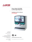
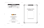
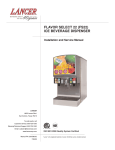
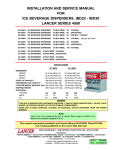
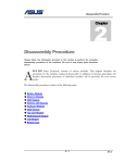
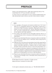
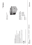
INSTALLATION AND SERVICE MANUAL
FOR
FLAVOR SELECT 30 (FS30)
ICE BEVERAGE DISPENSER
LANCER SERIES 14800
85-14808-12
ICE BEVERAGE DISPENSER, ABOVE COUNTER MULTI BRAND,
30 INCH WIDE, 8 BRANDS / 12 FLAVORS, 115V/60Hz
85-14808N-12
ICE BEVERAGE DISPENSER, ABOVE COUNTER MULTI BRAND,
30 INCH WIDE, 8 BRANDS / 12 FLAVORS, 115V/60Hz
85-14810-12
ICE BEVERAGE DISPENSER, ABOVE COUNTER MULTI BRAND,
30 INCH WIDE, 10 BRANDS / 12 FLAVORS, 115V/60Hz
85-14810N-12
ICE BEVERAGE DISPENSER, ABOVE COUNTER MULTI BRAND,
30 INCH WIDE, 10 BRANDS / 12 FLAVORS, 115V/60Hz
85-14812-12
ICE BEVERAGE DISPENSER, ABOVE COUNTER MULTI BRAND,
30 INCH WIDE, 12 BRANDS / 12 FLAVORS, 115V/60Hz
85-14812N-12
ICE BEVERAGE DISPENSER, ABOVE COUNTER MULTI BRAND,
30 INCH WIDE, 12 BRANDS / 12 FLAVORS, 115V/60Hz
85-14814-12
ICE BEVERAGE DISPENSER, ABOVE COUNTER MULTI BRAND,
30 INCH WIDE, 14 BRANDS / 12 FLAVORS, 115V/60Hz
85-14814N-12
ICE BEVERAGE DISPENSER, ABOVE COUNTER MULTI BRAND,
30 INCH WIDE, 14 BRANDS / 12 FLAVORS, 115V/60Hz
85-14816-12
ICE BEVERAGE DISPENSER, ABOVE COUNTER MULTI BRAND,
30 INCH WIDE, 16 BRANDS / 12 FLAVORS, 115V/60Hz
85-14816N-12
ICE BEVERAGE DISPENSER, ABOVE COUNTER MULTI BRAND,
30 INCH WIDE, 16 BRANDS / 12 FLAVORS, 115V/60Hz
PELLET ICE
PELLET ICE
PELLET ICE
PELLET ICE
PELLET ICE
This manual supersedes and replaces 28-0558/01, dated 03/17/05.
6655 LANCER BLVD. • SAN ANTONIO, TEXAS 78219 USA • (210) 310-7000
FAX SALES
• NORTH AMERICA – 210-310-7245 • INTERNATIONAL SALES – 210-310-7242 • CUSTOMER SERVICE – 210-310-7242 •
• LATIN AMERICA – 210-310-7245 • EUROPE – 32-2-755-2399 • PACIFIC – 61-8-8268-1978 •
FAX Engineering: • 210-310-7096
"Lancer" is the registered trademark of Lancer • Copyright — 2006 by Lancer, all rights reserved
DATE:
03/06/06
P.N. 28–0558/02
SPECIFICATIONS
DIMENSIONS
30" WIDE
HEIGHT:
WIDTH:
DEPTH:
39.625 INCHES (100.7 cm)
30.00 INCHES (76.2 cm)
30.50 INCHES (77.5 cm)
TOTAL ICE CAPACITY:
280 LBS (127.0 KG)
DISPENSABLE ICE CAPACITY:
210 LBS ( 95.3 KG)
COUNTER WEIGHT (WITHOUT ICE): 390 LBS (177.0 KG)
SHIPPING WEIGHT:
420 LBS (138.6 KG)
ELECTRICAL
VOLTAGE:
AMPS:
Hz:
115
7.0
60
WARNING
THIS UNIT IS EQUIPPED WITH AUTOMATIC AGITATION. IT MAY ACTIVATE UNEXPECTEDLY. DO
NOT PLACE HANDS, OR FOREIGN OBJECTS IN THE ICE STORAGE COMPARTMENT.
WHEN UNIT IS BEING SERVICED, CLEANED, OR SANITIZED, UNPLUG DISPENSER FROM THE
POWER SOURCE.
NOTE
Lancer does not recommend the use of shaved, flake, nugget, or pellet ice in dispensers not properly
equipped to do so (see Section 6.2, this manual).
29"
(737 mm)
26 1/2"
(673 mm)
30"
(762 mm)
8 3/4"
(222 mm)
14 5/8"
(372 mm)
18 3/4"
(476 mm)
4 1/2"
(114 mm)
39 5/8"
(1006 mm)
5 1/2"
(140 mm)
10"
(254 mm)
23"
(584 mm)
7 1/2"
(190 mm)
5 1/8"
(130 mm)
30 1/2"
(775 mm)
The FS30 Dispenser, Lancer Series 14800
i
MANUFACTURERS INTRODUCTION - High Volume Free Standing Fountain Drink Dispenser
The unit is designed with the highest quality components to be user and service friendly. The FS30 is designed to be
ready to use out-of-the-box as long as there is a steady water supply, BIB (Bag-In-Box) syrups with their pumps,
and a regulated CO2 supply. It will seamlessly interface with the Lancer Ice Link ice transport system to provide
for a minimum of labor and maintenance by store personnel.
The FS30 features a casted-in cold carbonator within the cold plate. It has a removable probe that regulates the
mixture of CO2 and plain water. The unit is equipped with a pressure (PSI) relief valve and a maintenance-free
water pump with backflow preventer for the carbonator. The cold plate has been designed and tested to meet the
highest performance and health standards. The design allows for a single drain and the ability for up to 16 independent
brands to be dispensed through four (4) Lancer Multi-Flavor dispense nozzles. A total of 12 "bonuses" (ambient flavors) may
be added to the drink via the flavor injection system on four (4) nozzles. The bonus flavors are plumbed independently to
each of the nozzles allowing for a multitude of customer pleasing drink combinations.
Supplier Name:
Address:
Phone:
Lancer
6655 Lancer Blvd
San Antonio, TX 78219
(800) 729-1500
Local Service Name: __________________________________________
Local Service Phone #: ________________________________________
TABLE OF CONTENTS
SPECIFICATIONS...............................................................................................................................................i
MANUFACTURERS INTRODUCTION ..............................................................................................................ii
TABLE OF CONTENTS .....................................................................................................................................ii
1. INSTALLATION ...........................................................................................................................................1
1.1 RECEIVING........................................................................................................................................1
1.2 UNPACKING ......................................................................................................................................1
1.3 SELECTING COUNTER LOCATION .................................................................................................2
1.4 INSTALLING THE DISPENSER.........................................................................................................2
1.5 OPTIONAL INSTALLATION OF SOLD-OUT DEVICE .......................................................................4
2. CLEANING AND SANITIZING INSTRUCTIONS ........................................................................................4
2.1 GENERAL INFORMATION ................................................................................................................4
2.2 REQUIRED CLEANING EQUIPMENT...............................................................................................5
2.3 DAILY CLEANING ..............................................................................................................................5
2.4 ICE BIN CLEANING - START UP AND MONTHLY ...........................................................................6
2.5 CLEANING AND SANITIZING BEVERAGE COMPONENTS - FIGAL SYSTEMS............................6
2.6 CLEANING AND SANITIZING BEVERAGE COMPONENTS - BAG-IN-BOX SYSTEMS.................7
3. HOW TO OPERATE AND ADJUST THE LANCER FS30 ..........................................................................8
3.1 NORMAL OPERATION ......................................................................................................................8
3.2 PROGRAMMING AND SETUP SOFTWARE.....................................................................................8
3.3 PURGING THE CARBONATION SYSTEM .....................................................................................10
3.4 PURGING THE WATER AND SYRUP SYSTEM .............................................................................10
3.5 ADJUSTING WATER FLOW (LFCV®) .............................................................................................10
3.6 WEEKLY ADJUSTING OF WATER TO SYRUP (RATIO) BRIX (LFCV®) ........................................11
3.7 CARBONATOR PUMP MODIFICATIONS........................................................................................11
3.8 PRIMING THE SYRUP PUMP AT THE CORRECT PRESSURE ....................................................11
3.9 REPLENISHING BIB (BAG-IN-BOX) SYRUP SUPPLY ...................................................................11
4. TROUBLESHOOTING GUIDE FOR THE FS30 DISPENSER..................................................................12
5. EXTRA CAPABILITIES .............................................................................................................................15
5.1 AUTOMATIC AGITATION AND RESETTABLE BREAKER..............................................................15
5.2 DIAGNOSTIC ...................................................................................................................................15
6. ILLUSTRATIONS, PARTS LISTINGS, AND WIRING DIAGRAMS ..........................................................17
6.1 FINAL ASSEMBLY ......................................................................................................................17-18
6.2 PELLET ICE ASSEMBLY AND PARTS LISTING.............................................................................19
6.3 WIRING DIAGRAM - 115V/60HZ (FIGURE SCHEMATICS) ...........................................................20
6.4 PLUMBING DIAGRAM WITH VALVE WIRING................................................................................21
ii
1. INSTALLATION
1.1
RECEIVING
Each unit is completely tested under operating conditions and thoroughly inspected before
shipment. At time of shipment, the carrier accepts the unit and any claim for damage must be made
with the carrier. Upon receiving units from the delivering carrier, carefully inspect carton for visible
indication(s) of damage. If damage(s) exist(s), have carrier note same on bill of lading and file claim
with carrier.
1.2
UNPACKING
A.
B.
C.
D.
E.
Set shipping carton upright on the floor.
Cut band and remove.
Open top of carton and remove interior packing.
Lift carton up and off of the dispenser.
Remove wood shipping base from the bottom of the dispenser. (Support dispenser while
removing shipping base to prevent damage to the dispenser.)
NOTE:
Please refer to specific icemaker
model for proper air intake/exhaust
ventilation with Lancer units.
39.625" (1006.5 mm)
SUFFICIENT CLEARANCE FOR
FILLING MANUALLY WITH ICE,
WHEN ICE MAKER NOT USED
10" (254 mm)
DISPENSE HEIGHT
30 1/2" (775 mm)
MINIMUM of 6" (152 mm)
clearance above ice maker
UT
AI
AIR
AIR
T
OU
AI
R
IN
IN
MINIMUM of 6" (152 mm)
wall clearance
39.625" (1006.5 mm)
6" (152 mm) clearance
6" (152 mm) clearance
T
U
O
R
R
O
R
AI
OU
T
AI
MINIMUM of 6" (152 mm)
clearance above ice maker
30" (762 mm)
30 1/2" (775 mm)
Figure 1
1
1.3
SELECTING COUNTER LOCATION (SEE FIGURE 1)
WARNING
THIS APPLIANCE MUST BE EARTHED. THIS DISPENSER MUST BE ELECTRICALLY
GROUNDED TO AVOID DANGER TO THE OPERATOR. THE POWER CORD PROVIDED HAS
A THREE PRONG GROUNDED PLUG. IF A THREE HOLED GROUNDED ELECTRICAL
OUTLET IS NOT AVAILABLE, USE AN APPROVED METHOD OF INSURING A PROPER
GROUND TO THE DISPENSER.
CAUTION
FAILURE TO DISCONNECT THE MOTOR POWER SUPPLY WILL DAMAGE THE CARBONATOR
MOTOR AND PUMP AND VOID THE WARRANTY.
A. Select a location close to a properly grounded 20 Amp electrical outlet, convenient to an open
type drain, access for soda, water, and syrup lines. It should have sufficient clearance above
the unit to provide for servicing.
1. If at all possible, location should be away from direct sunlight or other heat sources.
2. Connecting lines may be run through access in back of the unit or extend down through a
counter cutout.
3. Check the dispenser serial number plate for correct electrical requirements of unit. Do not
plug into wall electrical outlet unless the current shown on the serial number plate agrees with local
current available.
4. The counter must support the weight of the dispenser, ice, and possibly an icemaker. Total
weight may exceed 800 pounds (363.6 kg).
B. Unit may be installed directly on the countertop or on optional leg kit (PN 82-3484). If installed
directly on the counter, the unit must be sealed to the countertop. If an icemaker is to be
mounted on top of dispenser, do not install dispenser on legs.
NOTE
Water pipe connections and fixtures directly connected to a potable water supply must all be
sized, installed, and maintained according to Federal, State, and Local laws.
The water supply must be protected by means of an air gap, a backflow prevention device
(located upstream of the CO2 injection system) or another approved method to comply with NSF
standards. A backflow prevention device must comply with ASSE and local standards. It is the
responsibility of the installer to ensure compliance.
C. Location must insure sufficient clearance on sides, top and back of unit is provided for
ventilation and air circulation (see Figure 1).
D. Additionally, if an ice maker is not top mounted on the unit, sufficient clearance should be
provided [a minimum of 16 inches (40.6 cm) is recommended] to allow filling the unit with ice
from a five (5) gallon (19 liter) container (see Figure 1).
1.4
INSTALLING THE DISPENSER
A. Remove Cup Rest, Drip Tray, Splash Plate, and Top Cover.
B. Remove Cover Plate at rear of unit if not a through-the-counter installation.
C. Connect plain water supply line and water supply for carbonator to the 3/8 inch barb fittings at
the front of the unit (See Figure 2).
D. For the plain water supply line, the inlet water flowing pressure should be at least 75 PSI.
If the water pressure is lower than 75 psi flowing, a Water Booster system must be used.
NOTE:
The Lancer Water Booster/Tank, PN MC-163172, is offered as a kit.
The Water Booster must be installed as close as possible to the plain water circuit inlet.
If the water flowing pressure is lower than 75 PSI at the plain water inlet, and a water booster
is NOT installed, all water products will not hold a proper flow rate and/or water/syrup ratio.
Additionally, flow conditions at the nozzle may be affected, for example, poor nozzle coning and
mixing.
2
E. For the soda water supply line, the inlet water static pressure going into the carbonator pump
should NOT exceed 50 PSI. If the static water pressure exceeds 50 psi, a water regulator must
be installed before the carbonator water inlet.
NOTE:
The regulator (Lancer PN 18-0306) must be installed as close as possible to the water
carbonator pump inlet.
The water pressure value feeding the carbonator is recommended to be at a minimum of 25 PSI.
If the normal water pressure does not exceed 50 psi, but fluctuates over this value (for
example, when water usage on other equipment connected to the same water supply causes
pressure “spikes”), the use of a water regulator is also required.
F.
G.
H.
I.
J.
K.
L.
Place CO2 Cylinder with regulator in a serviceable location and route CO2 supply line (75 PSI)
to the 1/4 inch flare fitting at the front of the unit (See Figure 3). Check for leaks.
Connect syrup supply lines to the 3/8 inch barb inlet fittings at the front of the unit (See
Figure 4), using BIB (Bag-In-Box) pumps. Check for leaks.
Connect flavor injection lines to the barb fittings at the front of the unit (See Figure 4). Check
for leaks.
Install Drip Tray and extend hose to open type drain.
Drain lines must be insulated with a closed cell insulation. Insulation must cover the entire
length of the drain hose, including fittings. The drain should be installed in such a manner that
water does not collect in sags or other low points, as condensation will form.
Install Cup Rest and Splash Plate.
Connect Power Cord to grounded electrical outlet.
WARNING:
ICE AUGER AND BIN AGITATION SYSTEM WILL OPERATE AUTOMATICALLY.
PLACE HANDS OR ANY BODY PARTS WITHIN THE BIN OR IN THE ICE CHUTE.
M. Test Motor operation by pushing Ice Chute.
Flavor Injection Inlets
Water Inlets
Figure 2
Syrup Connections
Figure 4
CO2 Inlet
Figure 3
3
DO NOT
N.
O.
P.
Q.
Clean and sanitize dispenser (see Section 2).
Fill unit approximately half full with ice. Push Chute and check for ice delivery.
Fill unit with ice.
Install Top Cover.
NOTE
Lancer does not recommend the use of shaved, flake, nugget, or pellet ice in dispensers not
properly equipped to do so (see Section 6.2, this manual).
R. Set brix ratio for beverage dispensing valves according to manufacturer's instructions.
IMPORTANT NOTICE
WHEN INSTALLING AN ICEMAKER ON AN IBD UNIT, A BIN THERMOSTAT OR OTHER MEANS
OF CONTROLLING THE ICE LEVEL MUST BE INSTALLED. FAILURE TO DO SO COULD
RESULT IN DAMAGE TO THE DISPENSING MECHANISM AND VOID THE WARRANTY.
DURING THE AUTOMATIC AGITATION CYCLE AND/OR WHILE DISPENSING ICE, THERE
MUST BE ADEQUATE ROOM BETWEEN THE TOP OF THE ICE LEVEL AND THE BOTTOM OF
THE ICEMAKER SO THAT THE ICE CAN MOVE WITHOUT OBSTRUCTION.
CONTACT YOUR ICEMAKER SUPPLIER FOR INFORMATION ON PROPER BIN THERMOSTAT.
CAUTION
BEFORE REMOVING ANY PARTS IN THE BIN, ENSURE THE UNIT IS DISCONNECTED FROM
THE POWER SOURCE. AUTOMATIC AGITATION MAY GO OFF AT ANY TIME, AND THE
AGITATOR MAY CAUSE INJURY.
1.5
OPTIONAL INSTALLATION OF SOLD-OUT DEVICE
A. An optional Sold-Out Device can be used to automatically shut off the Syrup Pump when the
Package(s) is empty. This stops the operation of the Pump and the exhaust of gas until a new
syrup package is connected to the Pump.
B. The Lancer Sold-Out device measures syrup vacuum in the Pump Inlet Line. When the Syrup
Package is empty, the Pump increases vacuum causing the device to shut off the gas pressure
to stop the Pump. The Lancer Sold-Out automatically resets, after new Syrup Packages are
connected.
2. CLEANING AND SANITIZING INSTRUCTIONS
2.1
GENERAL INFORMATION
A. Lancer equipment (new or reconditioned) is shipped from the factory cleaned and sanitized in
accordance with NSF guidelines. This equipment must be cleaned and sanitized after
installation is complete, and the operator of the equipment must provide continuous
maintenance as required by this manual and/or state and local health department guidelines to
ensure proper operation and sanitation requirements are maintained.
NOTE
The cleaning and sanitizing procedures provided herein pertain to the Lancer equipment
identified by this manual. If other equipment is being cleaned, follow the guidelines established
for that equipment.
B. Cleaning and sanitizing should be accomplished only by trained personnel. Sanitary gloves are
to be used during cleaning and sanitizing operations. Applicable safety precautions must be
observed. Instruction warnings on the product being used must be followed.
C. Water lines are not to be disconnected during the cleaning and sanitizing of syrup lines to avoid
contamination.
D. Do NOT use strong bleaches or detergents. They tend to discolor and/or corrode various
materials.
E. Do NOT use metal scrapers, sharp objects, steel wool, scouring pads, abrasives, solvents, etc.,
on the dispenser.
F. Do NOT use hot water above 140°F (60°C). This may damage certain materials.
4
2.2
REQUIRED CLEANING EQUIPMENT
A. Cleansers (for example, Ivory Liquid, Calgon, etc.) mixed with clean, potable water at a
temperature of 90 to 110 degrees Fahrenheit should be used to clean equipment. The mixture
ratio, using Ivory Liquid, is one (1) ounce of cleanser to two (2) gallons of water. A minimum of
five (5) gallons of cleaning mixture should be prepared. Any equivalent cleanser may be used
as long as it provides a caustic based, non-perfumed, easily rinsed mixture containing at least
two (2) percent sodium hydroxide (NaOH). Rinsing must be thorough and use clean, potable
water which is also at a temperature of 90° to 110°F.
NOTE
Extended lengths of product lines may require that an additional volume of cleaning solution be
prepared.
B. Sanitizing solutions should be prepared in accordance with the manufacturer's written
recommendations and safety guidelines. The solution must provide 50 to 100 parts per million
(PPM) available chlorine. A minimum of five (5) gallons of sanitizing solution should be
prepared. Any sanitizing solution may be used as long as it is prepared in accordance with the
manufacturer's written recommendations and safety guidelines, and provides 50 to 100 parts
per million (PPM) available chlorine. Sanitizing solution is to be purged from line(s) and
equipment by flushing with product only until there is no after taste. Do not rinse with water.
NOTE
Please note that a fresh water rinse cannot follow sanitization of equipment. Purge only with
the end use product until there is no after taste in the product. This is an NSF requirement, since
residual sanitizing solution left in the system could create health hazards.
Extended lengths of product lines may require that an additional volume of sanitizing solution
be prepared.
C. Other
1.
2.
3.
4.
5.
2.3
Clean cloth towels.
Bucket.
Small brush (PN 22-0017) - included with installation kit.
Extra nozzle.
Sanitary gloves.
DAILY CLEANING
A. Carefully remove the nozzle housings by turning counter-clockwise and pulling down from the
nozzle body (see Figure 5).
Figure 5
Figure 6
B. Wash the nozzle housings in warm soapy water and rinse with clean warm water.
C. Wet a clean cloth in warm soapy water.
D. While the nozzle housing is removed, wipe down the perimeter and end of the nozzle body (see
Figure 6).
5
E. Fill a cup with clean warm water and rinse nozzle body.
F. Make certain that the nozzle o-ring is not torn or otherwise damaged. If necessary, replace
damaged o-ring with LANCER PN 02-0231.
G. Wet the inner surface of the nozzle housing with water and reinstall the nozzle housing by
sliding it over the nozzle body and turning clockwise to lock in position.
2.4
ICE BIN CLEANING - START UP AND MONTHLY
A.
B.
C.
D.
E.
Disconnect Dispenser from power source.
Remove Top Cover
Melt out any remaining ice from the bin.
Remove Splash Plate, Drip Tray and front and rear bin covers.
Remove Agitator Pin from Agitator Shaft. Slide Agitator Shaft rearward out of Motor Shaft and
pull out of rear Bearing to remove.
F. Remove Dispensing Wheel from Motor Shaft by sliding rearward.
G. Remove Dispensing Wheel Shroud.
1. For white dispensing wheel shroud:
a. Remove the gasket, which secures the shroud, by pulling it out.
b. Push the front section back (see Figure 7).
c. Pull the shroud up and out (see Figure 8).
Figure 7
Figure 8
H. Using cleaning solution, described in Section 2.2, and a clean cloth or soft brush, clean all
removable parts, sides of Ice Bin, Ice Chute, and surface of aluminum casting.
I. Using hot water, thoroughly rinse away the cleaning solution.
J. Wearing sanitary gloves, soak a clean cloth towel in sanitizing solution, described in Section 2.2,
and wash all surfaces of removable parts, sides of Ice Bin, Ice Chute, and surface of aluminum
casting.
K. Wearing sanitary gloves, reassemble all removable parts.
L. Fill unit with ice and replace Top Cover.
NOTE
Lancer does not recommend the use of shaved, flake, nugget, or pellet ice in dispensers not
properly equipped to do so (see Section 6.2, this manual).
M. Reconnect Dispenser to power source.
2.5
CLEANING AND SANITIZING BEVERAGE COMPONENTS - FIGAL SYSTEMS
NOTE
Extended lengths of product lines may require more time for flushing and rinsing lines than stated
below.
A. Disconnect syrup lines from syrup containers (for example, quick disconnects, figal containers,
etc.).
B. Connect hose half of syrup line to a syrup tank filled with clean, potable, room temperature
6
water. Connect CO2 supply hose to tank and pressurize.
C. Activate valve until water is dispensed. Flush and rinse line and fittings for a minimum of
60 seconds to remove all traces of residual product.
WARNING
TO AVOID POSSIBLE PERSONAL INJURY OR PROPERTY DAMAGE, DO NOT ATTEMPT TO
REMOVE SYRUP TANK COVER UNTIL CO2 PRESSURE HAS BEEN RELEASED FROM TANK.
D. Disconnect CO2 supply hose from the water filled syrup tank.
E. Following the instructions as described in Section 2.2 above, mix appropriate amount of
cleaning solution. Fill a tank with this solution. Connect hose half of syrup line to the tank.
Connect CO2 supply hose to tank and pressurize.
F. Activate valve and draw cleaning solution through lines for a minimum of 60 seconds. This will
ensure line is flushed and filled with cleaning solution. Allow line to stand for at least
30 minutes.
G. Disconnect CO2 supply hose from the tank.
H. Connect hose half of syrup line to a tank filled with clean, potable, water at a temperature of
90° to 110°F. Connect CO2 supply hose to tank and pressurize.
I. Activate valve to flush and rinse line and fittings for a minimum of 60 seconds to remove all
traces of cleaning solution. Continue rinsing until testing with phenolpthalein shows that the
rinse water is free of residual detergent.
WARNING
TO AVOID POSSIBLE PERSONAL INJURY OR PROPERTY DAMAGE, DO NOT ATTEMPT TO
REMOVE SYRUP TANK COVER UNTIL CO2 PRESSURE HAS BEEN RELEASED FROM TANK.
J. Disconnect CO2 supply hose from the tank.
K. Following the instructions as described in 2.2 above, mix appropriate amount of sanitizing
solution. Fill a tank with this solution. Connect hose half of syrup line to the tank. Connect
CO2 supply hose to tank and pressurize.
L. Activate valve and draw sanitizing solution through line for a minimum of 60 seconds. This
will ensure line is flushed and filled with sanitizing solution. Allow line to stand for at least
30 minutes.
M. Disconnect CO2 supply hose from the tank.
N. Reconnect syrup lines to syrup containers (for example, quick disconnects, figal containers,
etc.) and ready unit for operation.
O. Draw drinks to refill lines and flush the sanitizing solution from the dispenser.
NOTE
Please note that a fresh water rinse cannot follow sanitization of equipment. Purge only with
the end use product until there is no after taste in the product. This is an NSF requirement.
P. Test dispenser in normal manner for proper operation. Taste dispensed product to ensure there
is no off-taste. If off-taste is found, additional flushing of syrup system may be required.
Q. Repeat cleaning, rinsing, and sanitizing procedures for each valve and each circuit.
2.6
CLEANING AND SANITIZING BEVERAGE COMPONENTS - BAG-IN-BOX SYSTEMS
NOTE
Extended lengths of product lines may require more time for flushing and rinsing lines than
stated below.
A. Disconnect syrup quick disconnect coupling from syrup packages and connect coupling to a bag
valve removed from an empty Bag-in-Box (BIB) package.
B. Place syrup inlet line in a clean container filled with clean, potable, room temperature water.
C. Activate valve until water is dispensed. Flush and rinse line and fittings for a minimum of
60 seconds to remove all traces of residual product.
D. Following the instructions as described in 2.2 above, mix appropriate amount of cleaning
solution in a clean container. Place syrup inlet line in container filled with cleaning solution.
E. Activate valve and draw cleaning solution through lines for a minimum of 60 seconds. This
will ensure line is flushed and filled with cleaning solution. Allow line to stand for at least
7
30 minutes.
Place syrup inlet line in a clean container filled with clean, potable, water at a temperature of
90° to 110°F.
G. Activate valve to flush and rinse line and fittings for a minimum of 60 seconds to remove all
traces of cleaning solution. Continue rinsing until testing with phenolpthalein shows that the
rinse water is free of residual detergent.
H. Following the instructions as described in 2.2 above, mix appropriate amount of sanitizing
solution in a clean container. Place syrup inlet line in container filled with sanitizing solution.
I. Activate valve and draw sanitizing solution through line for a minimum of 60 seconds. This
will ensure line is flushed and filled with sanitizing solution. Allow line to stand for at least
30 minutes.
J. Remove bag valve from quick disconnect coupling and reconnect syrup inlet line to syrup
package. Ready unit for operation.
K. Draw drinks to refill lines and to flush the chlorine sanitizing solution from the dispenser.
F.
NOTE
Please note that a fresh water rinse cannot follow sanitization of equipment. Purge only with the
end use product until there is no after taste in the product. This is an NSF requirement.
L. Test dispenser in normal manner for proper operation. Taste dispensed product to ensure there
is no off-taste. If off-taste is found, additional flushing of syrup system may be required.
M. Repeat cleaning, rinsing, and sanitizing procedures for each valve and each circuit.
3. HOW TO OPERATE AND ADJUST THE LANCER FS30
3.1
NORMAL OPERATION
A. Fill cup with desired amount of ice.
B. Place cup under nozzle below desired brand.
C. Select up to two (2) desired bonus flavors from those available on the keypad, by pressing
against the flavor label once. Selection indicator light will illuminate, acknowledging
selection(s).
D. Press and hold brand label to fill cup.
E. Top off cup as desired
3.2
PROGRAMMING AND SETUP SOFTWARE
A. INTRODUCTION
NOTE:
The following descriptions reflect Firmware Versions: Controller Board: 0.405 and the Valve
Board: 1.100. Lancer reserves the right to make changes and updates as required. If you have
any questions regarding the latest versions of programs, please contact your Lancer
representative.
1. The Lancer FS30 has been factory preset to the settings necessary to comply with the
brand/flavor version of the unit requested by the customer.
2. Adjustments or upgrades should only be performed by trained personnel. For any
upgrades, an upgrade kit may be purchased. It will include all of the hardware required for
the upgrade, including bezels and valves.
3. The valves can be adjusted by scrolling through the menus (see Figure 9) using the UP and
DOWN arrows. By pressing the ENTER button, a submenu is revealed. In the submenu,
the individual valves can be adjusted to the desired configuration.
B. MENUS AND SUBMENUS
1. Bonus Flavors
a. Decide if the bonus flavors will be set to add an injected flavor to the brands or dispense
carbonated water/plain water.
b. Choose the Valve number (1-4) by scrolling UP and DOWN arrows.
c. Use the LEFT and RIGHT arrows to shift to the Top, Middle, or Bottom "bonus" flavors
categories.
8
d. Press the UP and DOWN arrows under Top, Middle, or Bottom to select it as an
injected flavor, carbonated Soda water, or plain Water. (NOTE: Water is NOT an option
for Valves 1 and 4.)
e. Press ENTER to finalize settings. Panel lights should confirm finalized configurations.
INITIALIZATION SCREEN
(BOOT UP ONLY)
LANCER FS-16
VER. 0.40000
MAIN MENU
SUB-CATEGORY
FS-16 SETUP
MAJOR / MINOR
BRANDS PER SIDE
V:1 L:2 R:1
FS-16 SETUP
CONFIG BONUS KEY
BONUS KEY SETUP
V:1 T:F M:S B:W
FS-16 SETUP
SODA / PLAIN WATER
CARB / WATER SET UP
V:2 1:S 2:W 3:S 4:W
FS-16 SETUP
CFG DISPENSE DLY
DISPENSE DELAY
V:1 B1 DLY1
FS-16 SETUP
PC MODE
SET PC MODE
OFF
ON
FS-16 SETUP
PC TIME
ON TIME (MSEC)
05000
FS-16 SETUP
ICE STIR OFF
OFF TIME (MIN)
00060
FS-16 SETUP
ICE STIR ON
ON TIME (MSEC)
02000
FS-16 SETUP
SOLD OUT
FS-16 SETUP
CARB SENSORS
SET DELAY (MS)
00075
UPPER
307
SOLD OUT #1
V:1 B:1
LOWER
579
FS-16 SETUP
VALVE CODE VER
12 1.100 1.100
34 1.100 1.100
FS-16 SETUP
RESET DEFAULTS
2ND SUB-CATEGORY
SOLD OUT #1
OFF
ICE BIN OPTIC
125
FS-16 SETUP
Press "Enter" to save changes
Press "Cancel" to exit menus
SELECT SOLD OUT
SOLD OUT #1
FS-16 SETUP
ICE BIN SENSORS
NUMBER OF VALVES
Scrolls through Main Menu
Press "Enter" to enter sub-category
Moves cursor to right or left
Changes value (number/letter)
4
3
OFF ON
2
ON
1
ON
RELOAD DEFAULTS?
NO
YES
CANCEL
ENTER
Main Menu Layout
Figure 9
2. Brands
a. Decide how the brands will be setup.
b. Choose the Valve number (1-4) by scrolling UP and DOWN arrows.
c. Use the LEFT and RIGHT arrows to shift to the Left or Right categories. The Left or
Right categories are set with the assumption that you are looking at them from the front.
d. Press UP and DOWN arrows under Left (1-2) or Right (1-2) to select the brand per side
9
as a single or double. For example, for bezel PN 05-2120, V:1 L:1 R:2
3. Soda/Water
a. Decide which switch locations will be carbonated and/or non-carbonated drinks.
(NOTE: Only adjustable on Valves 2 and 3.)
b. Choose the Valve number (2-3) by scrolling the UP and DOWN arrows.
c. Use the LEFT and RIGHT arrows to shift to the number categories (1-4). The number
categories correspond to the brand location (per valve) that is being configured.
d. Press the UP and DOWN arrows under the number to select if that brand will be
carbonated Soda or non-carbonated plain Water. If a single brand per side, only
number 1 and/or 3 need to be set.
4. Sold Out (Optional Accessory; PN 82-3546)
a. Decide which brands will have the sold out capabilities. Currently, the motherboard can
only support eight (8) brands to have the capability.
b. Choose the Valve number (1-4) by scrolling the UP and DOWN arrows.
c. Use the LEFT and RIGHT arrows to shift to the number categories (1-4). The number
categories correspond to the brand location (per valve) that is being configured.
d. Press the UP and DOWN arrows under the number to select if that brand will have Sold
out capabilities or if it will have the sold out capability Disabled. If a single brand per
side, only number 1 and/or 3 need to be set.
3.3
PURGING THE CARBONATION SYSTEM
A. A. Turn power off.
B. Turn the pressure adjusting screw on the CO2 regulator counter-clockwise, all the way out.
C. The relief valve for the built-in carbonator is located on the right hand side behind the dispenser
splash plate. Lift the yellow lever on the top of the relief valve until water flows from the holes
in the relief valve. Allow pressure on the regulator to drop and then lock the relief valve lever
into place.
D. Turn the pressure adjusting screw on the CO2 regulator clockwise, until there is resistance.
Open the CO2 cylinder handle slowly. Turn the CO2 pressure regulator up (clockwise) slowly to
75 PSIG (5.1 bar).
E. Reconnect the power supply. Built-in carbonator pump will activate periodically to fill
carbonator with the appropriate amount of CO2.
NOTE
To check for CO2 leaks, close the valve on the CO2 cylinder and observe if the pressure to the
system drops with the cylinder valve closed for five (5) minutes. Open the cylinder valve after
check.
3.4
PURGING THE WATER AND SYRUP SYSTEMS
A.
B.
C.
D.
3.5
Open a dispensing valve until water and syrup are flowing steadily from the valve.
Repeat procedure "A" for each valve.
Check all of the unit's syrup and water connections for leaks and repair if necessary.
Replace the unit's splash plate and cup rest.
ADJUSTING WATER FLOW (LFCV®)
A. The water flow can be adjusted between 3.25 oz/sec (96 ml/sec) and 4.50 oz/sec (133 ml/sec)
on all dispensing valves using the following procedure.
B. Ice should be on the cold plate for at least one (1) hour before you attempt to brix the valves.
The drink temperature should be no higher than 40°F (4.4°C) when the brix is set.
C. Remove dispenser merchandiser assembly.
D. Rotate switches panel, forward and down by releasing the two pin latches on its sides.
E. Rotate light panel, forward and up by releasing the two pin latches on its sides towards the top.
F. Remove nozzle by twisting counter clockwise and pulling down.
G. Install Lancer syrup separator (PN 54-0362) in place of nozzle.
H. Activate dispensing valve to fill separator syrup tube.
I. Hold a Lancer brix cup under the syrup separator and dispense water and syrup into cup for four
10
(4) seconds. Divide number of ounces (ml) of water in cup by four (4) to determine water flow
rate per second.
J. To obtain the proper flow, remove protective cap, and use a screwdriver to adjust water flow
control.
K. Repeat process for each "water valve". There can be up to six (6) gray "water valves" on this
dispenser [up to four (4) carbonated "water valves" and two (2) plain "water valves"].
3.6
WEEKLY ADJUSTING OF WATER TO SYRUP (RATIO) BRIX (LFCV®)
A.
B.
C.
D.
E.
F.
G.
3.7
Hold the Lancer brix cup under the syrup separator and activate valve. Check brix.
To obtain the proper brix, use screwdriver to adjust syrup flow control.
Once proper ratio is obtained repeat to verify.
Remove syrup separator (PN 54-0362; installed in Section 3.5.G above).
Install nozzle.
Repeat process for each valve.
Once all of the valves have been brixed, restore switches panel and light panel to their original
positions.
CARBONATOR PUMP MODIFICATIONS
NOTE
The electric, positive displacement, rotary vane pump with replaceable (250 PSI) bypass, is
maintenance-free. Only trained personnel should service pump. Additionally, it is not
recommended that the pump be used with hard water.
A. Servicing
1.
2.
3.
4.
5.
6.
3.8
Turn unit off.
Remove drip tray and splash plate.
Turn the CO2 off, activate the relief valve.
Once the pressure has been released, untighten the inlet/outlet nuts into/out of the pump
Unscrew the mounting bracket.
Part should easily slide out for replacement/maintenance.
PRIMING THE SYRUP PUMP AT THE CORRECT PRESSURE
For the Syrup Pump to operate correctly, it is necessary to remove all air from the system. After all
lines to the Syrup Pump and Syrup Packages are connected and CO2 (or air pressure) is set, the
system should be primed as follows:
A. Disconnect Wire to Soda Solenoid or close Shut Off Valve on soda side so that only syrup will
be dispensed when Dispensing Valve is operated.
B. Operate Valve for five (5) seconds and then release for five (5) seconds. Continue drawing
syrup until flow is steady and full.
C. After priming, look for air pockets in Syrup Inlet or Outlet Lines. Repeat priming to remove any
air pockets found.
D. After priming, replace the Wire to Soda Solenoid or open Soda Shut Off Valve on Dispensing
Valve.
E. Repeat above procedure for all Syrup Pumps.
3.9
REPLENISHING BIB (BAG-IN-BOX) SYRUP SUPPLY
A. Remove empty Syrup Package from system by turning Collar on Quick Disconnect Coupling
counterclockwise.
B. On a new Package, push in on tab located above perforated opening flap.
C. After breaking seal on flap, pull the flap up.
D. Reach in the box and pull the Bag Valve out. Remove the Dust Cap.
E. Connect the Quick Disconnect Coupling by turning the Collar clockwise until stopped by the Bag
Valve.
F The Lancer Sold-Out Device will reset automatically.
G. If air has entered the Syrup System, prime the Syrup Pump following the instructions in
Section 3.3
11
4. TROUBLESHOOTING GUIDE FOR FS30 DISPENSER
TROUBLE
CAUSE
REMEDY
4.1
No product when
switch is activated.
(Switch panel does
NOT light up when
activated).
4.2
No product when
A. 25-pin valve harness
switch is activated
is disconnected.
(switch panel DOES
B. Faulty switch assembly.
light up when activated). C. Faulty product solenoid.
A. Turn off power, reconnect 25-pin
harness, and restore power.
B. Replace switch assembly.
C. Replace solenoid assembly.
4.3
Push Chute and
nothing happens.
A. Dispenser not connected
to power source.
B. Microswitch defective.
C. Wiring Harness not
plugged in.
D. PC Board defective.
A. Connect Dispenser to power
source.
B. Replace Microswitch.
C. Plug in Wiring Harness.
Push Chute. Ice Door
opens but Motor does
not run.
A. Wiring Harness not
plugged in.
B. PC Board defective.
C. Motor defective.
A. Plug in Wiring Harness.
Push Chute. Motor
runs but Ice Door
does not open.
A. Solenoid not connected to
PC Board.
B. Solenoid defective.
C. PC Board defective.
D. Solenoid bracket screwed
too low and not opening
completely.
A. Connect Solenoid to PC board.
Push Chute, Ice Door
opens, Motor runs,
but no ice dispenses,
or ice is of poor quality.
A. Dispenser is out of ice.
B. Agitator Pin is missing or
damaged.
C. Poor ice quality.
4.7
Valves do not operate.
A. Keyswitch is off, or Keyswitch
harness disconnected.
B. Circuit Breaker tripped.
C. Unit not plugged in.
A. Turn Keyswitch and/or make sure
Keyswitch harness is connected.
B. Reset Circuit Breaker.
C. Plug in Dispenser.
4.8
Water in Ice Bin.
A. Coldplate Drain is obstructed.
A. Remove Splash Plate to obtain
access to Drain tubes and clear
accordingly.
4.9
Water leakage around
nozzle.
A. Damaged or improperly
installed o-ring on Nozzle.
A. If damaged, replace. If improperly
installed, adjust.
A. Gap between parts.
A. Tighten appropriate retaining
screws.
B. Replace or adjust appropriate
O-rings.
4.4
4.5
4.6
4.10 Miscellaneous leakage.
A. Keyswitch is off, or Keyswitch
harness disconnected.
B. 9-pin valve harness is
disconnected.
C. Faulty switch assembly.
D. No power to unit.
B. Damaged or improperly
installed O-rings.
A. Turn Keyswitch "ON" and/or
reconnect Keyswitch harness.
B. Turn off power, reconnect 9-pin
harness, and restore power.
C. Replace switch assembly.
D. Check internal breaker and
incoming power.
D. Replace PC Board.
B. Replace PC Board.
C. Replace Motor.
B. Replace Solenoid.
C. Replace PC Board.
D. Unscrew solenoid bracket, raise
solenoid and re-screw bracket.
A. Fill unit with ice.
B. Replace Agitator Pin.
C. Install water filtration/purification
to ice maker supply water.
4.11 Noisy/Cavitating
Carbonator Pump
A. Insufficient incoming water
supply pressure.
A. Verify incoming supply water
pressure to Carbonator Pump is a
minimum of 25 psi Carbonator
Pump (maximum of 50 psi).
4.12 Insufficient "Soda" flow.
(Carbonated drinks)
A. Insufficient CO2 supply
pressure.
B. Shutoff on mounting block
not fully open.
A. Verify incoming CO2 pressure
between 70 - 75 psi.
B. Open shutoff fully.
(Section 4.12 is continued on the next page.)
12
TROUBLE
CAUSE
REMEDY
(Section 4.12 is continued from the previous page.)
4.13 Insufficient Water flow.
(Plain Water drinks)
C. Foreign debris in Soda Flow
Control.
C. Remove Soda Flow Control from
valve and clean out any foreign
material to ensure smooth spool
movement.
A. Insufficient incoming supply
pressure.
A. Verify incoming supply water
pressure to Plain Water inlet is a
minimum of 75 psi (maximum of
125 psi).
B. Open shutoff fully.
B. Shutoff on mounting block
not fully open.
C. Foreign debris in Water flow
control.
4.14 Insufficient syrup flow.
D. Water filtration problem.
C. Remove Water Flow Control from
valve and clean out any foreign
material to ensure smooth spool
movement.
D. Service water system as required.
A. Insufficient CO2 pressure to
BIB pumps.
A. Adjust CO2 pressure to 80 psi
(Minimum: 70 psi) for BIB pumps.
NOTE: Do NOT exceed manufacturer’s pressure recommendations.
B. Shutoff on mounting block
not fully open.
C. Foreign debris in syrup flow
control.
D.
4.15 Erratic ratio.
Defective BIB Pump.`
A. Incoming water and/or syrup
supply not at minimum
flowing pressure.
B. Foreign debris in water and/or
syrup flow control.
C. CO2 regulator malfunction.
4.16 Water only dispensed;
no syrup; or syrup only
dispensed; no water.
A. Syrup BIB empty.
B. Water or syrup shutoff on
mounting block not fully open.
C. Improper or inadequate water
or syrup supply.
D. CO2 pressure to syrup
pump(s) too low.
E. Stalled or inoperative
BIB pump.
F. Kinked line.
G. CO2 Regulator malfunction.
4.17 Valve will not shut off.
A. Debris in solenoid seat.
B. Solenoid plunger "sticking"
13
B. Open shutoff fully.
C. Remove Syrup Flow Control from
valve and clean out any foreign
material to ensure smooth spool
movement.
D. Replace pump.
A. Check pressure and adjust.
B. Remove flow control from
suspected valve and clean out any
foreign material to ensure smooth
smooth spool movement.
C. Repair or replace CO2 regulator,
as required.
A. Replace syrup BIB as required.
B. Open shutoff fully.
C. Remove valve from mounting block
and open shutoffs slightly and
check water and syrup supply. If
no supply, check dispenser for
or other problems. Ensure BIB
connection is engaged.
D. Check the CO2 pressure to the
pump to ensure it is between
70 - 80 psi.
E. Check CO2 pressure and/or
replace pump.
F. Remove kink or replace line.
G. Repair or replace CO2 regulator
as required.
A. Activate valve a few times to try
and free debris. If that doesn't
eliminate the problem, remove the
solenoid coil and plunger, and
clean out any foreign material.
B. Replace Solenoid coil.
TROUBLE
CAUSE
REMEDY
4.18 Syrup only dispensed.
No water, but CO2 gas
dispensed with syrup.
A. Improper water flow to
dispenser.
B. Carbonator pump motor has
timed out. (A message will
be displayed on the LCD
screen).
C. Liquid level probe not
connected properly to PCB.
D. Faulty PCB assembly.
E. Faulty liquid level probe.
4.19 Excessive foaming.
A. No ice in bin.
B. Incoming water or syrup
temperature too high.
C. CO2 pressure too high.
A. Check for water flow to dispenser.
B. Reset by turning the unit OFF and
and then ON (by using the Circuit
Breaker on the Power Supply, or
momentarily unplugging unit).
C. Check connections of liquid level
probe to PCB assembly.
D. Replace PCB assembly.
E. Replace liquid level probe.
A. Fill bin with ice , and allow
coldplate to re-stabilize.
B. Correct prior to dispenser.
C. Water flow rate too high.
E. Nozzle and diffuser not clean.
F. Air in BIB lines.
C. Adjust CO2 pressure downward,
but not less than 70 psi.
D. Readjust and reset ratio.
E. Remove and clean.
F. Bleed air from BIB lines.
4.20 Water continually
leaking at connections.
A. Loose water connection(s).
B. Flare seal washer leaks.
A. Tighten water connections.
B. Replace flare seal washer.
4.21 Water leaking from
Ice Door.
A. Securing screws loosened.
B. Ice Door improperly seated.
A. Tighten screws.
B. Reattach door assembly to
dispenser.
4.22 Circuit breaker tripping.
A. Valve wire harness(es)
shorted to itself or Faucet
Plate.
A. Detect short by disconnecting valve
harnesses from Switch Panel
[(4) 25-pin harnesses and
(4) 9-pin harnesses].
Restore power. If breaker does
NOT trip, then find and replace
shorted harness. If breaker still
trips, re-install the (8) harnesses,
and proceed to Step B, below.
B. Detect by disconnecting the white,
5-pin harness from the controller
PCB. Restore power. If breaker
does NOT trip, then replace
controller PCB. If breaker still trips,
re-install the white 5-pin harness
and proceed to Step C, below.
C. Locate short from a motor or
solenoid harness, and replace as
necessary.
D. Detect short by disconnecting ALL
harness(es) connected to Power
Supply. Restore power. If breaker
still trips, replace Power Supply.
B. Controller PCB is bad.
C. Secondary wire harness
is shorted.
`
D. Power Supply is bad.
4.23 BIB pump does
not operate when
dispensing valve
is opened.
4.24 BIB pump operating,
but no flow.
A. Out of CO2, CO2 not turned
on, or low CO2 pressure.
B. Out of syrup.
C. BIB connector not tight.
D. Kinks in syrup or gas lines.
A. Leak in syrup inlet or outlet
line.
B. Defective BIB pump check
valve.
14
A. Replace CO2 supply, turn on CO2
supply, or adjust CO2 pressure to
70-80 psi.
B. Replace syrup supply.
C. Fasten connector tightly.
D. Straighten or replace lines.
A. Replace line.
B. Replace BIB pump.
TROUBLE
4.25 BIB pump continues to
operate when bag is
empty.
4.26 BIB pump fails to
restart after bag
replacement.
CAUSE
REMEDY
A. Leak in suction line.
B. Leaking o-ring on pump inlet
fitting.
C. Defective syrup BIB pump.
A. Replace line.
B. Replace o-ring.
A. BIB connector not on tight.
B. BIB connector is stopped up.
A. Tighten BIB connector.
B. Clean out or replace BIB
connector.
C. Straighten or replace line.
C. Kinks in syrup line.
C. Replace defective pump.
4.27 BIB pump fails to stop
when dispensing valve
is closed.
A. Leak in discharge line or
fittings.
B. Empty BIB.
C. Air leak on inlet line or bag
connector.
A. Repair or replace discharge line.
4.28 Low or no carbonation.
A. Low or no CO2.
A. Check CO2 supply. Adjust CO2
pressure to 70 psi.
B. Need water a booster kit.
C. Replace carbonator pump.
B. Low water pressure.
C. Worn or defective carbonator
pump.
D. Backflow preventer not
allowing water to flow.
E. Probe malfunctioning.
F. PCB malfunctioning.
B. Replace BIB.
C. Repair or replace.
D. Replace backflow preventer,
noting the flow direction arrow
(from pump-to-coldplate).
E. Replace Probe.
F. Replace PCB.
5. EXTRA CAPABILITIES
5.1
AUTOMATIC AGITATION AND RESETTABLE BREAKER
WARNING
THIS UNIT IS EQUIPPED WITH AUTOMATIC AGITATION. IT MAY ACTIVATE UNEXPECTEDLY.
DO NOT PLACE HANDS, OR FOREIGN OBJECTS IN THE ICE STORAGE COMPARTMENT.
WHEN UNIT IS BEING SERVICED, CLEANED, OR SANITIZED, UNPLUG DISPENSER FROM
THE POWER SOURCE.
A. Resettable breaker switch should not be used as a substitute for unplugging the dispenser from
power source to service unit.
B. Each Series 14800 ice beverage dispenser is equipped with automatic agitation for the ice bin.
The unit is shipped with timing set at two (2) second ON every 60 minutes.
5.2
DIAGNOSTIC
REPROGRAMMING
Only trained technicians should attempt any kind of reprogramming to new firmware version
releases.
15
NOTES
Please refer to the Lancer web site (www.lancercorp.com) for
information relating to Lancer Installation and Service Manuals,
Instruction Sheets, Technical Bulletins, Service Bulletins, etc.
16
6. ILLUSTRATIONS AND PARTS LISTINGS
6.1
FINAL ASSEMBLY
30
31
32
35
34
27
26
28
29
25
24
36
39
40
33
23
38
22
21
20
37
41
15
6
7
8
13 14
5
17 16
11
12
4
3
2
10
9
1
17
18
19
6.1
FINAL ASSEMBLY (CONTINUED)
Item Part No.
-
Description
85-14808-12
85-14810-12
85-14812-12
85-14814-12
85-14816-12
-
IBD, Above
IBD, Above
IBD, Above
IBD, Above
IBD, Above
85-14808N-12
85-14810N-12
85-14812N-12
85-14814N-12
85-14816N-12
IBD, Above
IBD, Above
IBD, Above
IBD, Above
IBD, Above
Item Part No.
1
2
3
4
5
6
7
8
9
10
11
12
13
14
15
Counter
Counter
Counter
Counter
Counter
Multi
Multi
Multi
Multi
Multi
Counter
Counter
Counter
Counter
Counter
Brand
Brand
Brand
Brand
Brand
Multi
Multi
Multi
Multi
Multi
Series
Series
Series
Series
Series
Brand
Brand
Brand
Brand
Brand
14800,
14800,
14800,
14800,
14800,
Series
Series
Series
Series
Series
Description
82-3177-01
30-8364
30-6147
91-0165
82-3196
17-0556
05-2257/01
54-0406
01-2214
52-2751
82-3370
54-0289
05-2120
82-3286/01
19-0262/01
18 04-1089
H
I
36
J
K
82-2317/01
52-2682/01
02-0406
82-3556
52-2352
05-1858
23-1373
10-0762
03-0368
28
29
30
31
32
05-1859
05-1555
05-1606
05-1476
05-1310/02
82-3490
12-0503
05-2070
82-1566
A 03-0086
B 04-0328
C 04-0327
D 12-0195
E 30-5165
F 23-1380
G 10-0496
H 03-0110
I 03-0111
J 30-8356
K 05-0546
L 03-0205
37 52-2693
38 52-2692
39 82-3284
40 25-0088
41 30-8871/01
42 10-0732
43 05-0359
44 03-0113
45 05-0928/01
F
G
19
20
21
22
23
24
25
26
27
33
34
35
36
D
L
115V/60Hz,
115V/60Hz,
115V/60Hz,
115V/60Hz,
115V/60Hz,
17 19-0260/01
A
B
C
E
14800,
14800,
14800,
14800,
14800,
8 brands / 12 flavors
10 brands / 12 flavors
12 brands / 12 flavors
14 brands / 12 flavors
16 brands / 12 flavors
Item Part No.
Drip Tray Assy
Splash Plate
Cover, Motor, IBD
Motor, Gear, 115V, 1/7 HP, IBD
Motor Assy, Carbonator
Check Valve, Vented, 5/8 x 18
Chute, IBD
Chute, Printed, Small Disp, IBD
Nut, Swivel, Probe, Carb
Body, Probe, Sub Assy, Carb,
CO2 Assy, Inlet/P-OFF
Nozzle Assy, Multi-Flavor, STHL
Bezel, Multi-Brand, 1L/2R
Switch Assy, MB, 2L/2R
Valve Assy, LFCV, 0.2, Syrup
Injection, Natural
Valve Assy, LFCV, 4.5,
Soda/Water, Gray
16 19-0261/02
115V/60Hz,
115V/60Hz,
115V/60Hz,
115V/60Hz,
115V/60Hz,
42
43 44
45
18
8 brands / 12 flavors, Pellet
10 brands / 12 flavors, Pellet
12 brands / 12 flavors, Pellet
14 brands / 12 flavors, Pellet
16 brands / 12 flavors, Pellet
Description
Valve Assy, LFCV, 4.5, Syrup,
Black
Screw, 10 - 32 x 1.000, RH,
PH/SL
Block Mounting Assy, SGL
PCB Assy, Main, MB-LFCV
Seal, Shaft, Motor, IBD
Dispensing Wheel, HD, IBD
Body Assy, Emitter, Sensor
Body, Emitter, Sensor, Plugged
Agitator Assy
Pin, Agitator, 1/4”, PASS
Retainer, RUE-14-S, Lancer Ice
Link
Body, Detector, Sensor, Plugged
Bearing, Agitator, Rear, IBD
Lid, Back, IBD30, Round
Lid, Front, IBD, Round
Shroud, Dispensing Wheel,
Modified
Reflector Assy, MAG
Bulb, Fluorescent, 26”, T8, CW
Merchandiser, Sub Assy, MB-IBD
Solenoid Assy, IBD
Ring, Retaining (5304-18)
Washer, Rubber
Washer, Flat
Solenoid, D-90
Bracket, Solenoid
Plunger Assy
Pin, Solenoid Assy
Spring, Solenoid
Ring, Retaining (5133-62)
Linkage, Door, IBD
Lever, Door,
Ring, Retaining (5304-25)
Harness, Valve, 25-PIN
Harness, Control-to-Valve, 9-PIN
Power Supply
Transformer, 115V/60Hz, 275VAC
Cover, power Supply
Shaft, ice Chute Door
Bushing, Shaft
Ring, Retaining (5144-12)
Trap Door, IBD
2
X X
19
8
X X
DESCRIPTION
Grommet, Rubber,
G3002
03-0368
Retainer, Pin,
Agitator, IBD
05-2293/01 Ice Shroud, IC
23-1401
Agitator Assy,
Helical, IC, HEX
23-1363
Extension Assy,
4 1/2”, IBD30
42-0109
Foamed Cover,
Scots/Hoshi,
Pellet Ice
30-9446
Adapter, Mech
Bin-Stat, Scots
82-3538
Ice Chute Assy,
IBD30, Pellet Ice
82-3651
Dispensing Wheel
Assy, Pellet Ice, HEX
30-9880
Shield, Nugget Ice,
One Piece with Tab
30-8832/01 Bracket, Valve Plate,
FS30
02-0577
PART NO.
1
1
1
1
1
1
1
1
1
1
3
QTY
*NOTE:
Item 5 is NOT used on the FS30 Dispenser.
An X in the left columns indicates the parts used in the
installation for an IBD30 Dispenser or an FS30
Dispenser.
An R next to the Item Number indicates new, revised
or realigned information.
X R 11
X X R 10
X X R 9
7
6
X X
X X
5
X
X X R 3
X X R 4
1
ITEM
X X
IBD30
NOTICE:
The Pellet Ice components listed are to be used ONLY in
conjunction with Nugget, Cubelet, or Chewblet ice.
LANCER makes no warranty of any kind with regard to
these components being used with any other kind of ice.
FS30
8
10
5
3
9
4
LABEL FOR
SCOTSMAN
ICE MAKER
(TO FRONT OF
DISPENSER)
6 (FOAMED
TOP COVER
ASSEMBLY)
11
ATTACH HERE
FOR SCOTSMAN
1
2
1
1
ADAPTER,
MECHANICAL
BIN STAT
7
ATTACH HERE
FOR HOSHIZAKI
LABEL FOR
HOSHIZAKI
ICE MAKER
(TO FRONT OF
DISPENSER)
6.2
PELLET ICE ASSEMBLY AND PARTS LISTING
20
SECONDARY
POWER
RELAY
24V
CARB
PUMP
CARBONATOR
PUMP
PRIMARY
115V
16V
BOARD
VALVE BOARD
(DIAGNOSTIC)
WHITE
AGITATOR
BALLAST AGITATOR
CARB
CAP
WHITE
1
2
3
4
SWITCH
NUMBER
X
O
O
O
O
X
O
O
O
O
X
O
O
O
O
O
MDB ADDRESS
FRONT VIEW
4
3
2
X = ON
O = OFF
TOP VIEW
SWITCH
ICE LINK NUMBER
RESETABLE
BREAKER
NOTE: ICE LINK IS ONLY
CAPABLE OF SUPPORTING 4 UNITS
BLACK
BLACK
1
SLIDE FORWARD
TO TURN OFF
SIDE VIEW
2
SOLD OUT
3
1
5
LOW HIGH
6
CARB
PUMP
SOLENOID
ICE LINK BIN OPTION
CARB
PROBE
4
7
BIN
AGITATE
ICE
DOOR
2
3
4
1 2 34
NOZZLE
NOZZLE
NOZZLE
MDB
SLAVE
8
SLIDE BACKWARD
TO TURN ON
PROBE
(OPTIONAL)
ICE LINK
BLACK
BLACK
WIRING DIAGRAM
OFF
POWER SUPPLY
RESET
RED
WHITE
RUN
+
ICE
DOOR
SWITCH
-
PROGRAM
VALVE STATUS
4 3 2 1
DISPENSE
SWITCH
KEY
SWITCH
FS16
ENTER
LOW ICE SENSOR
EMITTER
YEL
BLUE
BIN
SWITCH
(OPTIONAL)
LANCER
CANCEL
DISPLAY
REPROGRAMMING
(DIAGNOSTIC)
NOTE:
LED COMMUNICATION LIGHTS
FLASH WHEN COMMUNICATING
LOW ICE SENSOR
DETECTOR
LOW
ICE
LIGHT
LOW
ICE
ALARM
ICE
MAKER
(OPTIONAL)
1
NOZZLE
FS30
6.3
WIRING DIAGRAM - 115V/60HZ (Figure Schematics)
21
IS4-3
S4-2
S4-4
S4-3
WATER SODA
IS3-3
IS3-2
IS3-1
S0
FS30
IS2-3
IS2-2
IS2-1
S2-4
S2-3
V2
S2-2
S2-1
S0
RED
GRY
V2
S4-4 S4-3 S4-2 S4-1 S3-4 S3-3 S3-2
S3-1 S2-4 S2-3 S2-2 S2-1 S1-4 S1-3 S1-2 S1-1
IS1-3
IS1-2
IS1-1
YEL
GRY
V1
NOT
USED
CO2
S1-4
S1-3
S1-4
V1
S1-2
S1-1
S0
SODA1
S1-1
BRN
BLK
V1
BLU
BLK
V1
S1-3
RED
GRY
V1
YEL
BLK
V1
S1-2
RED
BLK
V1
BRN
BLK
V2
S2-4
BLU
BLK
V2
S2-3
YEL
BLK
V2
S2-2
WATER2 SODA2
YEL
GRY
V2
RED
BLK
V2
S2-1
BLU YEL RED BLU YEL RED
WHT WHT WHT WHT WHT WHT
V2
V2
V1
V1
V2
V1
IS2-3 IS2-2 IS2-1 IS1-3 IS1-2 IS1-1
IS4-3 IS4-2 IS4-1 IS3-3 IS3-2 IS3-1 IS2-3 IS2-2 IS2-1 IS1-3 IS1-2 IS1-1
S3-4
S3-3
VALVE HARNESS
DIAGRAM
V3
S3-2
S3-1
SODA3 WATER3
PLUMBING
DIAGRAM
V4
S4-2
IS4-2
IS4-1
S0
SODA4
S4-4
YEL
GRY
V3
RED
BLK
V3
S3-1
RED
GRY
V3
YEL
BLK
V3
S3-2
BLU
BLK
V4
S4-3
BLU
BLK
V3
S3-3
YEL
BLK
V4
S3-4
RED
GRY
V4
S4-1
BRN
BLK
V4
BRN
BLK
V3
RED
BLK
V4
S4-1
YEL
GRY
V4
NOT
USED
BLU YEL RED BLU YEL RED
WHT WHT WHT WHT WHT WHT
V4
V4
V3
V3
V4
V3
IS4-3 IS4-2 IS4-1 IS3-3 IS3-2 IS3-1
F
I
T
T
I
N
G
S
I
N
L
E
T
P
A
N
E
L
N
O
Z
Z
L
E
M
O
U
N
T
I
N
G
V
A
L
V
E
6.4
PLUMBING DIAGRAM WITH VALVE WIRING