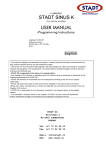
1
Series MP ELECTRONIC METERING PUMPS Installation Operation Maintenance Instruction READ ALL WARNINGS CAREFULLY BEFORE INSTALLING SAFETY INSTRUCTIONS When using chemical feed pumps, basic safety precautions should always be followed to reduce risk of fire, electric shock, and personal injury. Failure to follow these instructions could result in death or serious injury. READ ALL INSTRUCTIONS *** : Secure chemicals and metering pumps, making them inaccessible to children and pets. *** DO NOT PUMP FLAMMABLE LIQUIDS. *** Do not cut the plug or ground lug off the electrical cord. Consult a licensed electrician for proper installation or replacement. ** : Always wear protective clothing, including gloves and safety glasses, when working on or near chemical metering pumps. ** Inspect tubing regularly for cracking or deterioration and replace as necessary. (Always wear protective clothing and safety glasses when inspecting tubing.) ** Use CAUTION to keep fingers away from rotating parts. ** If pump is exposed to direct sunlight, use a U.V. resistant tubing. ** Follow directions and warnings provided from the chemical manufacturer. The user is responsible for determining the chemical compatibility with the chemical feed pump. ** Make sure the voltage on the pump name tag matches the installation voltage. If pump fails to start, check line voltage. ** Consult with local health officials and/or qualified water conditioning specialists when treating potable water. ** Always depressurize system prior to installation or disconnecting the metering pump tubing. ** If injection point is lower than the chemical tank and pump, install an anti-siphon valve. ** DO NOT MODIFY PUMP. This poses a potentially dangerous situation and will void the warranty. * : All pumps are factory tested with water. Remove tubing and thoroughly dry if the chemical being pumped will react with water (for example sulfuric acid). * Hand tighten plastic connections (Do not use wrench). * Consult licensed plumber and electrician before installation to conform to local codes. * NOTE: For accurate volume output, pump must be calibrated under all operating conditions. 2 TABLE OF CONTENTS Page SAFETY INSTRUCTIONS ............................................................................................................................... 2 INTRODUCTION.............................................................................................................................................. 4 UNPACKING THE PUMP ................................................................................................................................ 5 PRECAUTIONS FOR OPERATION ................................................................................................................ 6 INSTALLATION, PIPING AND WIRING ......................................................................................................... 8 DESCRIPTION OF CONTROLS AND OPERATION..................................................................................... 12 CONTROL OPTIONS .................................................................................................................................... 13 RELAY SETTINGS ........................................................................................................................................ 14 ALARMS......................................................................................................................................................... 15 CONTROL REFERENCE SUMMARY........................................................................................................... 16 START-UP AND OPERATION ...................................................................................................................... 18 ADDITIONAL SETTINGS............................................................................................................................... 23 MAINTENANCE ............................................................................................................................................. 24 TROUBLESHOOTING ................................................................................................................................... 26 EXPLODED VIEW DRAWINGS..................................................................................................................... 27 PUMP SPECIFICATIONS.............................................................................................................................. 29 REPAIR SERVICE ......................................................................................................................................... 30 3 INTRODUCTION These installation, operation and maintenance instructions cover your electronic metering pump. Refer to the pump nameplate to determine the actual model. PRINCIPLE OF OPERATION Diaphragm metering pumps are used to dispense chemicals or fluids. This is achieved by an electromagnetic drive mechanism (solenoid) which is connected to a diaphragm. When the solenoid is pulsed by the control circuit, it displaces the diaphragm which, through the use of check valves, moves the fluid out the discharge under pressure. When the solenoid is de-energized it returns the diaphragm and pulls more fluid into the pump head and the cycle repeats. The stroke rate of the pumps is controlled via the touchpad and present status is indicated by the LCD display. The stroke length is controlled via the stroke length knob. MATERIALS OF CONSTRUCTION The wetted materials (those parts that contact the solution being pumped) available for construction are Glass filled polypropylene, PVC, SAN, Hypalon, Viton, PTFE, 316 Stainless Steel, PVDF, Ceramic and Alloy C. These materials are very resistant to most chemicals. However, there are some chemicals, such as strong acids or organic solvents, which cause deterioration of some elastomer and plastic parts, such as the diaphragm, valve seats, or head. Consult Chemical Resistance Guide or Supplier for information on chemical compatibility. Various manufacturers of plastics, elastomers and pumping equipment publish guidelines that aid in the selection of wetted materials for pumping commercially available chemicals and chemical compounds. Two factors must always be considered when using an elastomer or plastic part to pump chemicals. They are: 1. The temperature of service: Higher temperatures increase the effect of chemicals on wetted materials. The increase varies with the material and the chemical being used. A material quite stable at room temperature might be affected at higher temperatures. 2. Material choice: Materials with similar properties may differ greatly from one another in performance when exposed to certain chemicals. MANUFACTURER’S PRODUCT WARRANTY Pulsafeeder warrants all pumps and controllers of its manufacture to be free of defects in material or workmanship. Liability under this policy extends for 24 months from date of shipment from the factory. The manufacturer’s liability is limited to repair or replacement of any failed equipment or part which is proven defective in material or workmanship upon manufacturer’s examination. This warranty does not include removal or installation costs and in no event shall the manufacturer’s liability exceed the selling price of such equipment or part. The manufacturer disclaims all liability for damage to its products through improper installation, maintenance, use or attempts to operate such products beyond their functional capacity, intentionally or otherwise, or any other unauthorized repair. The manufacturer is not responsible for consequential or other damages, injuries or expense incurred through the use of its products. Above warranty is in lieu of any other warranty, whether expressed or implied. The manufacturer makes no warranty of fitness or merchantability. No agent of ours is authorized to provide any warranty other than the above. The European Union Warranty address is listed below, however, please note that the seller should be contacted first. Steigar 24 NL 1351 AB Almere Netherlands 4 EUROPEAN TECHNICAL FILE LOCATION PO Box 91 Washington NE37 1YH United Kingdom UNPACKING THE PUMP Check all equipment for completeness against the order and for any evidence of shipping damage. Shortages or damages should be reported immediately to the carrier and to the seller of the equipment. The carton should contain: - Metering Pump - Clear Flexible Suction Tubing* - Stiff White Discharge Tubing* - Foot valve/Strainer Assy.* - Backpressure Injection Valve Assy. - One Instruction Book that you are now reading - Bleed Valve Assembly* (most models) *These items are included with the standard pump. Items may or may not be included depending on model. Make sure that all items have been removed from the shipping carton before it is discarded. 5 PRECAUTIONS FOR OPERATION Each Electronic Metering Pump has been tested to meet prescribed specifications and safety standards. Proper care in handling, installation and operation will help in ensuring a trouble free installation. Please read all these cautionary notes prior to installation and start-up of your metering pump. 1. Important: Pump must be installed and used with supplied back pressure/injection valve. Failure to do so could result in excessive pump output flow. 2. Handle the pump with care. Dropping or heavy impact causes not only external damage to the pump, but also to electrical parts inside. 3. Install the pump in a place where the ambient temperature does not exceed 40°C (104°F). The pump is water resistant and dust proof by construction and can be used outdoors, however do not operate the pump submerged. To avoid high internal pump temperatures, do not operate in direct sunlight. 4. Install the pump in a place convenient for its future maintenance and inspection, then fix it to prevent vibration. 5. Protective caps must be removed prior to installing tubing onto valve assemblies. Use tubing of specified size. Connect the tubing to the suction side securely to prevent the entrance of outside air. Make sure that there is no liquid leakage on the discharge side. 6. Be careful to check that the voltage of the installation matches the voltage indicated on the pump nameplate. Each pump is equipped with a three prong plug. Always be sure the pump is grounded. To disconnect, do not pull wire but grip the plug with fingers and pull out. Do not use the receptacle in common with heavy electrical equipment which generates surge voltage. It can cause the failure of the electronic circuit inside the pump. 7. Tampering with electrical devices can be potentially hazardous. Always place chemicals and pump installation well out of the reach of children. 8. Never repair or move the metering pump while operating. Always disconnect electrical power. For safety, always wear protective clothing (protective gloves and safety glasses) when working on or near chemical metering pumps. 9. An air bleed valve is available for most models with tubing connections. Air purges should be performed when the pump chamber contains no fluid at the time of start-up. As a safety measure, connect the return tubing to the air bleed valve and bypass fluid back to storage tank or a suitable drain. 10. Chemicals used may be dangerous and should be used carefully and according to warnings on the label. Follow the directions given with each type of chemical. Do not assume chemicals are the same because they look alike. Always store chemicals in a safe location away from children and others. We cannot be responsible for the misuse of chemicals being fed by the pump. Always have the material safety data sheet (MSDS) available for any fluid being pumped. 11. All pumps are pretested with water before shipment. Remove head and dry thoroughly if you are pumping a material that will react with water, (i.e. sulfuric acid, polymers). Valve seats, ball checks, gaskets, and diaphragm should also be dried. Before placing pump into service, extreme care should be taken to follow this procedure. 12. Valve cartridges are stamped to indicate fluid flow direction. Always install so that markings read from top to bottom, with the arrow pointing in the direction of flow. 13. When metering hazardous material DO NOT use plastic tubing, strictly use proper rigid pipe. Consult supplier for special adapters or valve assemblies. 14. Pump is NOT to be used to handle or meter flammable liquids or materials. 15. Standard white discharge tubing is not recommended for installations exposed to direct sunlight. supplier for special black tubing. Consult 16. Factory will not be held responsible for improper installation of pump, or plumbing. All cautions are to be read thoroughly prior to hook-up and plumbing. For all installations a professional plumber should be consulted. Always adhere to local plumbing codes and requirements. 6 17. When using pump with pressurized systems, make sure the pressure of the system does not exceed the maximum pressure rating on the pump nameplate. Be sure to de-pressurize system prior to hook up or disconnecting the metering pump. 18. Electronic power modules are equipped with automatic reset thermal overload devices and may reset unexpectedly. 19. The pump is designed to operate using a backpressure/injection valve. If the discharge point is below the liquid level of the source or if the discharge pressure is less than the suction pressure, siphoning may occur. To correct this condition, install an anti-siphon valve or other anti-siphon device. Check local regulations which may apply. (Ref. Figure G1). 20. If the power cord is unplugged or in the event of electrical power interruption while the pump is operating, the pump will remember its last operating state for years and will resume operation as before, whenever power is restored. 7 INSTALLATION, PIPING AND WIRING The metering pump should be located in an area that allows convenient connections to both the chemical storage tank and the point of injection. The pump is water resistant and dust proof by construction and can be used outdoors, however do not operate submerged. Avoid continuous temperatures in excess of 40°C (104°F). To do otherwise could result in damage to the pump. MOUNTING Typical mounting arrangements are shown in Figures B to E. Important: Injection point must be higher than the top of the solution supply tank to prohibit gravity feeding, unless a suitable backpressure is always present at the injection point. Installation of an antisiphon valve will prohibit gravity feeding. 1. For wall or shelf mounting, refer to Figure E. Connect suction tubing to suction valve of chemical pump. Suction valve is the lower valve. Tubing should be long enough so that the foot valve/strainer assembly hangs about 1-2 inches (2.5 - 5 cm) above the bottom of chemical tank. To keep chemical from being contaminated, the tank should have a cover. 2. Flooded suction mounting (installing the pump at the base of the chemical storage tank, Figure C) is the most trouble free type of installation and is recommended for very low output requirements. Since the suction tubing is filled with chemical, priming is accomplished quickly and the chance of losing prime is reduced. To mount pump, drill 4 holes of .25in. (6.3 mm) diameter in the shelf as shown in the dimension drawing (Figure F). Attach pump securely using four #10 bolts and nuts. 8 3. The pump can be mounted to a wall as shown in Figure D. A wall mount bracket kit is available which includes all necessary hardware to mount the pump to the wall. Mounting the pump other than as shown in Figure D defeats the purpose of the housing drain. Mounting dimensions for the pump are provided in Figure F for reference. 4. The pump can be mounted on top of a solution tank as shown in Figure E. Install chemical pump on the cover. Insert suction tubing through the center hole and cut tubing so foot valve/strainer hangs about 1 or 2 inches (2.5 - 5 cm) above the bottom of the tank. Mount the chemical pump rigidly by drilling four .25in. (6.3 mm) holes and using four #10 screws and nuts. 5. USE AN ANTI-SIPHON VALVE IN THE DISCHARGE LINE whenever the fluid pressure in the discharge line is below atmospheric pressure. This can occur if the injection point is on the suction side of a water pump or against a "negative" head such as when feeding down into a well, SEE FIGURE G1. 9 PIPING 1. Use provided tubing of specified size for connection. Connect tubing securely to prevent leakage of chemical and the entrance of air. Since plastic nuts are used for fittings, they should not be tightened excessively i.e. hand tighten only. NPT suction and discharge valves must NOT be over tightened. Hold fittings in place while adding piping and fittings. NPT suction and discharge valves should only be tightened 25 to 35 in. lbs. (4.46 to 6.25 kg/cm). 2. If the air bleed valve assembly is being used, a return line (tubing) should be securely connected and routed back to the storage tank. To avoid possible injury from chemicals do not attempt to prime using a bleed valve without installing a return line. 3. To maintain metering performance, a backpressure/injection valve is provided. The injection valve must be installed in the discharge line. Best practice is to install the injection valve at the point of chemical injection. 4. If the discharge tubing is going to be exposed to direct sunlight, black tubing should be used instead of the standard white translucent tubing supplied with each pump. To obtain, contact supplier. 5. To prevent clogging or check valve malfunction always install a strainer assembly to the end of the suction tubing (Figure E). This foot valve/strainer assembly should always be installed 1 to 2 inches (2.5 - 5 cm) above the bottom of the chemical tank. This will help prevent clogging the strainer with any solids that may settle on the tank bottom. The chemical tank and foot valve/strainer should be cleaned regularly, to ensure continuous trouble free operation. If the chemical being pumped regularly precipitates out of solution or does not dissolve easily or completely (e.g. calcium hydroxide), a mixer should be used in the chemical tank. These are readily available in many motor configurations and mountings. To obtain, contact supplier. 6. A flooded suction (tank liquid level always at a higher elevation than the pump) is recommended when pumping sodium hypochlorite (NaOCI) and hydrogen peroxide (H2O2) etc. which are liable to produce air bubbles. Maintaining a low liquid temperature will also help eliminate this problem. 7. Pipe corrosion can result if dilution at the injection point does not occur rapidly. This problem is easily prevented by observing this simple rule: install injection fitting so that the end is in the center of the flow stream of the line being treated. Trim injector tip as required. See Figure H. Note: Extended injection assemblies are available for large water lines. Consult your supplier for more information. 10 WIRING 1. : Risk of electrical shock. This pump is supplied with a three prong grounding type power plug. To reduce risk of electric shock, connect only to a properly grounded, grounding type receptacle. 2. The metering pump should be wired to an electrical source which conforms to those on the pump nameplate. (Applying higher voltage than the pump is rated for will damage the internal circuit.) 3. In the electronic circuit of the control unit, measures for surge voltage are made by means of surge absorbing elements and high voltage semiconductors. Nevertheless, excessive surge voltage may cause failure in some areas. Therefore, the receptacle should not be used in common with heavy electrical equipment which generates high voltage. If this is unavoidable, however, measures should be taken by (a) the installation of a surge absorbing element (varistor of min. surge resistance 2000A) to the power supply connection of the pump, or (b) the installation of a noise suppression transformer. 4. In the event of electrical power interruption during pump operation, the pump will remember its setting and automatically resume operation as before, whenever power is restored. If a manual reset is required to resume operation, the electrical circuit serving the pump must be suitably wired. Latching power relays which "drop out" upon loss of power, requiring manual reset, are typically used for this purpose. WELL PUMP SYSTEM INSTALLATION 1. Ensure that the metering pump voltage matches the voltage of the well pump. Typical well pump electrical circuits are shown in Figure J. All electric wiring should be installed in accordance to local electrical codes by a licensed electrician. 2. Install the backpressure/injection (Figure I) on the discharge side of the metering pump into a tee which is installed into the water line going to the pressure tank. Typical installations are found in figures G1, G2 and G3. Pumps carrying the "ETL Sanitation' approval (tested to NSF standard 50) are listed for swimming pools, spas, and hot tubs, and when proper materials are selected, are capable of handling but not limited to the following chemical solutions: 12% ALUMINUM SULPHATE 5% SODIUM CARBONATE 10% SODIUM HYDROXIDE 2%CALCIUM HYPOCHLORITE 12.5% SODIUM HYPOCHLORITE 10% HYDROCHLORIC ACID 11 DESCRIPTION OF CONTROLS AND OPERATION INTRODUCTION The pump performs the following functions: Selected Controls - Fixed Rate - External Pulse - Straight Pulses - Pulse Storage - Division - Multiplication - External Current Signal - 4-20 mA - 20-4 mA - Stroke Counting - Timed Operation (intervals) Display Alarms - Circuit Failure - Signal Loss - Full Count - Pulse Overflow - Pulse Rate High Relay Output (one selected at a time) - Relay Off - Pulse Overflow - Stop Function - Repeat Strokes - Current Signal Loss - Circuit Failure - Full Count - Flow Verification (if equipped with flow sensor) USING THE TOUCHPAD All adjustments and changes to pump operation (except stroke length) are made through the 6-button touchpad (figure L). Except for alarm conditions, the LCD display (figure K) always presents either the present operating condition or a prompt which must be answered in order to commence operation. There are two types of prompts: Prompts in the form of questions (marked with a flashing question mark) are used to navigate through the menu options. These prompts are answered by pressing either the or : buttons. Prompts marked with alternating up and down arrows are always encountered when a numerical value must be selected (i.e., stroke rates, counts, run times, ratios). These prompts are answered by pressing either the © or © buttons to change the display value to the desired setting. After the desired value has been set in the display, press to accept this value and continue or press : to return to the main menu. To stop the pump at any time, press the red resume operation as before, press the button. button. To To display the present stroking rate as a percentage of the maximum rate of the pump at any time, press the button. Press any button to return to the normal display. 12 HELPFUL HINTS You can always get to where you want to go simply by accepting or rejecting choices presented. If you find yourself within a menu where you don't want to be, keep selecting No until you return to the main menu. If you go past the desired selection by mistake, keep selecting No and the pump will take you back to it. A partly flashing display requires your response. A flashing question mark requires a Yes or No answer. Flashing arrows require an Up or Down numerical adjustment. To make large numerical adjustments quickly, hold down either the Up or Down arrow buttons. The value in the display will change at an increased rate. A fully flashing display is an alarm. If power is interrupted, the pump will automatically resume operating where it left off when power is restored. The pump will remember this while power is off. CONTROL OPTIONS FIXED RATE The pump operates continuously at the set rate over the span 1-100% of maximum. EXTERNAL PULSE CONTROL - STRAIGHT PULSES Each pulse received from the external signal port causes the pump to immediately stroke once at a rate limited by the maximum rate of the pump, 125 strokes per minute. In the Pulse Storage option, any pulse frequency received which is at a higher rate than the pump can respond to (125 contacts per minute), will cause excess pulses to be accumulated in memory. The pump will work off the excess pulses at a rate of 125 strokes per minute when the signal level drops below the maximum rate. If the accumulation exceeds 9,999 pulses, memory storage capacity is exceeded and the Pulse Overflow alarm is triggered. During the Pulse Overflow condition the pump operates at 125 strokes per minute; when the incoming rate drops below 125 pulses per minute, normal Pulse Storage operation resumes, starting with a full memory. EXTERNAL PULSE CONTROL - DIVISION The pump operates as described above except that incoming pulses are divided by a value from 1 to 999 prior to actuating the pump. For example, at a setting of 5, every fifth incoming pulse causes the pump to stroke once. The Pulse Storage option operates as described above. Pulse division makes it possible to "tune" the pump by adjusting its response to an external pulse signal, such as that from a flow meter, which is of too high a frequency to cause the desired feed by directly stroking the pump. 13 EXTERNAL PULSE CONTROL - MULTIPLICATION The pump operates as described previously except that incoming pulses are multiplied by a value from 1 to 999 prior to actuating the pump and then worked off at a selected stroking rate. For example, at a multiplier of 5 and a stroking rate of 25%, each incoming pulse causes the pump to stroke five times at 25% stroking rate and then stop. During operation, the display shows the present value and the present count on a running basis. Unless Pulse Storage is in effect, additional external pulses received while responding to a previous pulse are ignored. This option is similar to Stroke Counting (see below) except that action is initiated automatically by one or more external pulses rather than once manually by the user. There is no Full Count alarm as in Stroke Counting since it is always possible to receive additional external pulses. The Pulse Storage option operates as described above. EXTERNAL CURRENT SIGNAL CONTROL In the 4-20 mA option, the pump responds linearly to a current signal from the incoming signal port over the programmed operating rate. The rate can be any value from 0% to 100% and the current signal can be any value between 3.5 to 20.5 mA. The actual current signal can be calibrated to match that of the sending device. For example: if the pump was set for a low signal of 4mA, a high signal of 12mA, a low rate of 0%, and a high rate of 80% - an incoming signal of 10mA would cause the pump to stroke at 60%. The pump software allows the high and low rates to be inverted to produce a slower rate as the input signal is increased. For example: if the pump was set for a low signal of 4mA, a high signal of 12mA, a low rate of 100%, and a high rate of 20% - an incoming signal of 8mA would cause the pump to stroke at 60%. A Signal Loss alarm is triggered whenever the signal drops below approximately 2 mA. The pump stops operating during the loss of signal condition, and automatically resumes normal operation when the signal is restored. STROKE COUNTING The pump delivers a preset number of up to 9,999 strokes at a selected stroking rate. During operation, the display shows the preset value and the present count on a running basis. When the preset number of strokes has been delivered, the pump stops and the Full Count alarm is triggered. Pressing Yes when the Full Count alarm is displayed brings up the reset prompt. Continue pressing Yes to repeat the same stroking cycle or change the displayed values as they are presented to change the stroke count. This option is similar to External Pulse Control - Multiplication (see above) except that action is initiated once manually by the user rather than by one or more external pulses. TIMED OPERATION* The pump operates for selected run times from 1 to 999 minutes (16.65 hours) at selected intervals from 1 to 999 hours (41.625 days) at a selected stroking rate. For example, the pump might be set to operate for 60 minutes every 168 hours (7 days), at a 50% stroking rate. During operation the pump displays the run time in minutes and the interval in hours. RELAY SETTINGS The following relay output options can be brought up on the menu by pressing the Yes button while the pump is in the menu settings (Relay options vary with operating condition). Press the No button to scan through the options available. Only one relay output option may be selected. When the desired option is displayed, press the Yes button. This will set the relay for the chosen option. 14 RELAY OFF In all control options the relay remains open at all times. STOP FUNCTION In all control options the relay is normally open and closes while the Stop Function is activated through the stop port. CURRENT SIGNAL LOSS In any Current Signal control option, the relay is normally open and closes while the Signal Loss alarm is in effect. FULL COUNT In the Stroke Counting control option, the relay is normally open and closes while the Full Count alarm is in effect. PULSE OVERFLOW In any External Pulse control option with Pulse Storage, the relay is normally open and closes while the Pulse Overflow alarm is in effect. REPEAT STROKES In all control options, the relay is normally open and closes momentarily during each stroke of the pump. If the pump is equipped with a 24 VDC signal relay output, this function may be used to pace another externally paced pump. CIRCUIT FAILURE At all times, the relay is normally open and closes while the Circuit Failure alarm is in effect. The numbers which flash alternately with the alarm signal are for failure diagnosis at the factory. FLOW VERIFY If the pump is equipped with the flow verification option, the relay is normally open and closes while the Flow Failure alarm is in effect. ALARMS Alarms are distinguished by a fully flashing display. CIRCUIT FAILURE At all times, pumping is disabled and the pump will no longer operate until repaired. SIGNAL LOSS In any Current Signal option, the Signal Loss alarm is triggered whenever the signal drops below approximately 2 mA for several seconds. The pump stops operating during the loss of signal condition and resumes normal operation when the signal is restored. This includes the 20-4 mA option, in which a low current (4 mA) signal normally calls for full pump output in order to prevent overfeeding in the event of signal loss. FULL COUNT In the Stroke Counting control option, when the preset number of strokes has been delivered and the pump stops, the Full Count alarm is triggered. PULSE OVERFLOW In the Pulse Storage option, when memory capacity is exceeded the Pulse Overflow alarm is triggered. The pump continues to respond to external signal pulses as if 9,999 pulses were in storage. PULSE RATE HIGH In any External Pulse Control option without Pulse Storage, receipt of any pulses at a faster rate than maximum pump stroking rate, 125 strokes per minute, the Pulse Rate High alarm is triggered. The pump continues to operate at its maximum rate and does not respond to the excess pulses. FLOW FAILURE If the pump is equipped with the flow verification option, the pump will stop stroking and the screen will display Flow Failure when the flow sensor does not detect flow from the pumps discharge port. 15 CONTROL REFERENCE SUMMARY CONTROL OPTIONS Fixed Rate Fixed Rate 100% External Pulse Straight Straight Pulse Pulse Storage option Pulse-Store 9999 Pulses ) 999 Division Pulse Storage option: Multiplication ) 999 Store 999 x999/999 Pulse Storage option x999 Store 999 External Current Set High Rate Hi Rate 100% Set Low Rate Low Rate 100% Set High Signal Hi Sig 20.0mA Set Low Signal Low Sig 4.0mA Calibration Sig:xx.x Cal:xx.x Run 4-20mA? Count Strokes Count 9999/9999 Timed Interval 999m Every 999h OUTPUT RELAY OPTIONS Relay Off Relay Off Stop Function Relay-Stop Current Signal Loss Full Count Relay-No Signal Relay-Full Count External Pulse Overflow Repeat Strokes Circuit Failure Relay-Overflow Relay-Repeat Relay-Failure ALARMS (full flashing display) Circuit Failure Circuit Failure Signal Loss Signal Loss Full Count Full Count Pulse Overflow Pulse Overflow Pulse Rate High Pulse Rate High 16 SETTINGS OPTIONS Settings? Flow Verify? Yes=On No=Off Relay Output? Relay-Stop? Relay-Repeat? Rel-No Signal? Rel-Full Count? Relay-Overflow? Relay-Failure? Rel-Flow Vrfy? Relay-Off? Factory Init? Init Settings? Are You Sure? Volume-Units? Units = GPD? Units = LPD? Units = LPH? Reset Totals? Are You Sure? Calibrate Flow? Stroke = 100 Run Calib? Language? English? French? German? Spanish? 17 START UP AND OPERATION POWER All metering pumps are available in 115 volts at 50/60 Hertz, single phase. Optionally 230 volts at 50/60 Hertz, single phase can be provided. Prior to start-up always check to insure that the pump voltage/frequency/phase matches that of the power supply. : If pump is fitted with a PVC pump head (7th position of model number is “V”. Note: PVC is gray, not black), uniformly hand tighten the four head screws before use (18-22 inch pounds / 3.21-3.93 kg/cm). Periodically tighten after installation. : When working on or around a chemical metering pump installation, protective clothing and gloves and safety glasses should be worn at all times. PRIMING All pumps are tested with water. If the chemical to be pumped reacts when mixed with water (e.g. sulfuric acid, polymer) the pump head should be removed and dried thoroughly along with the diaphragm and valve seats. 1. Turn on the power to the pump. Operate the pump in the fixed rate control mode at 100% (full) rate. The green LED will light up and flash off each time the pump strokes. 2. Adjust the stroke length knob to the 100% setting mark (for more information see “Stroke Length Adjustment” on the following page). 3. If the discharge line is connected directly to a pressurized system it should be temporarily bypassed during priming of the pump. A bleed valve will simplify this operation by allowing easy bypass of the discharge fluid. All air must be purged from the pump head before the pump will pump against pressure. Air Bleed Operation: A) While pump is running, turn adjustment screw counterclockwise. B) Run with valve open until a solid stream of fluid comes out of the bypass tubing (1/4 x 3/8 supplied with valve), no air bubbles. C) Close air bleed valve by turning adjustment screw clockwise. 4. Chemical should reach the pump head after a few minutes of operation. If not, remove the discharge fitting and moisten the discharge valve area (ball check and valve seats) with a few drops of chemical being fed to the metering pump. For safety, always use protective clothing and gloves, wear safety glasses and use a proper container to hold the chemical. 5. If the pump continues to refuse to prime, refer to Troubleshooting Section of these instructions. 6. Turn the power on once more and adjust the pump flow to the desired rate (see “Controlling Procedure” below). 7. Always check the calibration of the pump after start-up. It’s best to calibrate the pump under your typical use conditions. 18 STROKE LENGTH ADJUSTMENT Stroke length can be controlled within 0 to 100% of the diaphragm displacement. (It should be controlled within 20 to 100% for practical use.) Stroke length can be set by means of the stroke length adjusting knob while the pump is in operation. Do not turn the knob while the pump is stopped. Controlling Procedure (for fixed rate): Proper set points for stroke length should be determined after consideration of the pump and characteristics of the fluid. The following procedure is recommended from the viewpoint of pump performance. Note: The closer the stroke length is to 100%, the better the pump performance will be. A) B) Set the stroke length to 100%. Measure the output capacity. Adjust the stroke rate frequency to obtain the desired output. If adjustment by stroke rate alone does not bring the output low enough, the stroke length may be adjusted to lower the maximum output. C) Measure the output capacity to ensure that the required value is obtained. Example Selected Model Set Stroke Length Set Stroke Rate Output Capacity (Rated Pressure) = = = = LMD4 100% 100% 21 GPD* Desired Flow Adjust Stroke Rate to 81% Output Capacity = 17 GPD = 17 x 100 = 81% (approx.)* 21 Thus to obtain the desired flow, stroke length is set at 100% and stroke rate is set at 81% i.e. output capacity = 0.81 x 21 = 17 GPD* * Check these values by measurement. Output capacity is higher when feeding against less than rated pressure. 19 OPERATION BY EXTERNAL INPUT SIGNALS: The pump can be controlled by three types of input signals. All are fully isolated from AC input power and from Earth ground. The input socket connections are located at the bottom of the control panel face and the signal cords are provided with the pump. Remove rubber plugs to access plug sockets. Stop Function: Operation of the pump can be stopped by an external signal input. When the external signal is input to the stop terminals, the red light goes on and operation of the pump is stopped. The stop function overrides all control options and input signals at other terminals. Previous operation resumes when the stop signal is removed. : Operation of more than one pump from the same contact closure will damage the pump circuits. When such operation is required, the pump circuits must be electrically isolated from one another by means of a multi-contact control relay or similar means. Input signals should be no-voltage signals from relay contacts, etc. and the input of other signals is prohibited. (In case of relay contacts, electric resistance must be 100 ohms or below when ON and 1 Mega ohm or above when OFF). The stop function is commonly used in conjunction with a tank float switch. The float switch contacts are normally open but when the tank level falls past a certain point the contacts close and the pump stops. Signal cord is provided with the pump. External Pacing Function: Pump stroking can be controlled by an external pulse signal through the external signal terminals while the pump is in one of the external pacing control modes. : Operation of more than one pump from the same contact closure will damage the pump circuits. When such operation is required, the pump circuits must be electrically isolated from one another by means of a multi-contact control relay or similar means. After receiving an input signal, the pump generates the necessary power pulse to actuate the solenoid. The external signal input is debounced by the pump circuit. Input signals should be no-voltage signals from relay contacts, etc. and the input of other signals is prohibited. (In the case of relay contacts, electric resistance must be 100 ohms or below when ON and 1 Mega ohm or above when OFF). The pulse duration of the input signal must be 10 milliseconds or over and the frequency of input signal must not exceed 125 times/min unless accommodated by pulse division or pulse storage. Signal cord is provided with the pump. 4-20 mA / 20-4 mA Function: The pump stroking rate can be controlled by a 4-20mA current signal when in current signal mode. The pump automatically adjusts the stroking rate according to the signal level provided to the pump. Pumps may be wired in series to the current signal providing that the signal source is sufficient to handle the load (each pump has an impedance of 100 ohms). 20 The pump responds to a 4-20mA signal as follows when the high rate is 100%, the low rate is 0%, the high signal is 20mA and the low signal is 4mA. (Figure O below shows straight response) 4-20 mA Signal 20 18 14 12 10 DC mA 16 8 6 0% 25% 50% 75% 4 100% Pump Speed Figure N The pump responds to a 20-4mA signal as follows when the high rate is 0% the low rate is 100%, the high signal is 20mA and the low signal is 4mA. However, the high signal can never be set below the low signal, and the low signal cannot be set above the high signal setting. Only the stroke rate may be inverted. (Figure O below shows straight response) 20-4 mA Signal 20 18 14 12 10 DC mA 16 8 6 100 75% 50% 25% 4 0% Pump Speed Figure O The pump responds to a user defined scaled signal as follows when the high rate is 100% the low rate is 0%, the high signal is 20mA and the low signal is 12mA. (Figure O-1 below shows an example of a possible user defined scale) Example of a Custom Scale 20 18 14 12 10 8 6 0% 50% Pump Speed Figure O - 1 The signal cord is provided with the pump and has the following polarity: White = Positive (+) Black = Common Signal input impedance is 100 ohms. 21 4 100% DC mA 16 OUTPUT RELAY Each pump has the option of being provided with one of two separate normally open output relay options as described below. Relays close according to the option selected, and remain closed during the condition specified for the selected option except for the Repeat Strokes option. The Signal Level output relay option is via the output signal terminals on the pump control panel. It is designed to provide direct or inverted voltage output signals as shown in figure O. The voltage input must have a high-impedance characteristic and must not exceed 24 VDC. The pump circuit can source or sink a maximum current of 10 mA. The signal cord is provided with the pump and has the following polarity when connected to the pump terminals. White = Positive (+) Black = Common The Power Level option is via the power relay cord which exits the pump below the control panel. The power level relay is a zero-crossing triac-type solid-state switch as seen in figure Q which is designed to switch AC current only and has the following ratings: Voltage Minimum = 12 VAC, 50/60 HZ Maximum = 250 VAC, 50/60 HZ Current minimum = 10 mAmps maximum = .5 Amps Power minimum = .12 watts (at 12 VAC) maximum = 120 watts (at 240 VAC) * Load can be any device which meets the above voltage and current limits (i.e., lamp, alarm, siren, relay, etc.) : Do not apply power directly to the relay cord without a sufficient load to limit current as indicated above. Do not exceed the specified voltage rating. Excess current or voltage will damage the pump and cause fire and electrical shock hazards. Do not install any type of standard power plug to the relay cord. 22 ADDITIONAL SETTINGS: “Flow Verify?” – used in conjunction with the flow verification meter; to activate this option: Choose: “Settings?”, press “YES” “Flow Verify?”, press “YES” “Yes=On No=Off?”, press “YES” NOTE: Enabling flow verification on a pump with no flow meter will cause a flow failure. “Factory Init?” – initializes the pump back to all original factory settings; to reinitialize the pump: Choose: “Settings?”, press “YES” “Factory Init?”, press “YES” “Init Settings?”, press “YES” “Are You Sure?”, press “YES” “Volume-Units?” – allows the user to select how the flow data will be displayed (default is GPD); to change this setting: Choose: “Settings?”, press “YES” “Volume-Units?”, press “YES” Use the up and down arrow to choose GPD, GPH, or LPH. Choose “YES” when the desired unit is displayed. “Reset Totals?” – resets the flow totals; to reset the totals: Choose: “Settings?”, press “YES” “Reset Totals?”, press “YES” “Are You Sure?”, press “YES” The display will read “Reset Done”, press “YES” to get back to the settings menu. “Calibrate Flow?” – allows the user to calibrate the system to obtain accurate flow totals; to calibrate the system: Choose: “Settings?”, press “YES” “Calibrate Flow?”, press “YES” “Stroke=100%”, use arrow keys to set the stroke per the dial, press “YES” “Run Calib?”, press “YES” Run the pump for the desired amount of time while measuring the flow output. Press “YES” to stop the calibration period. Use the arrow keys to enter the measured flow in mL, press “YES”. The display will read “Calibrated”, press “YES” to return to the Settings menu. NOTE: If the stroke length is changed and the calibration is not re-run, the flow totals will not be accurate. Additional Relay Functions: “Rel-Flow Vrfy?” – allows the relay to be activated if there is a flow failure. To set this option: Choose: “Settings?”, press “YES” “Rel-Flow Vrfy?”, press “YES” “Language?” – allows the user to select English (default), German, Spanish or French; to set the language: Choose: “Settings?”, press “YES” Use the arrow keys to select the desired language, press “YES”. 23 MAINTENANCE : Before performing any maintenance or repairs on chemical metering pumps, be sure to disconnect all electrical connections and insure that all pressure valves are shut off and pressure in the pump and lines has been bled off. Always wear protective clothing, gloves and safety glasses when performing any maintenance or repairs on chemical metering pumps. ROUTINE MAINTENANCE 1. Routinely check the physical operating condition of the pump. Look for the presence of any abnormal noise, excessive vibration, low flow and pressure output or high temperatures [when running constantly at maximum stroke rate, the pump housing temperature can be up to 160°F (70°C)] 2. For optimum performance, cartridge valves should be changed every 4-6 months. Depending on the application, more frequent changes may be required. Actual operating experience is the best guide in this situation. Repeated shortterm deterioration of valve seats and balls usually indicates a need to review the suitability of wetted materials selected for the application. Contact the supplier for guidance. 3. Check for leaks around fittings or as a result of deteriorating tubing e.g. when standard white translucent discharge tubing is exposed to direct sunlight. Take appropriate action to correct leak by tightening fittings or replacing components. 4. Keep the pump free of dirt/debris as this provides insulation and can lead to excessive pump temperatures. 5. If the pump has been out of service for a month or longer, clean the pump head/valve assemblies by pumping fresh water for approximately 30 minutes. If the pump does not operate normally after this “purging run”, replace cartridge valve assemblies. DISASSEMBLY AND ASSEMBLY DIAPHRAGM REMOVAL 1. Flush pump head and valve assemblies out by running pump on water or other suitable neutralizing solution. Wash outside of pump down if chemical has dripped on pump. 2. Set stroke length of pump to 0% and unplug pump. 3. Disconnect tubing or piping from the pump. Remove the four pump head screws and then remove the pump head assembly. 4. Remove the diaphragm by grasping it at the outer edges and turning it counterclockwise until it unscrews from the electronic power module (EPM). Don’t lose the deflection plate or diaphragm shims which are behind the diaphragm. Note shim quantity can be from 0 to 2. 5. Inspect diaphragm if it is intended to be used again. Look for indications of the TFE face being overstretched, (localized white areas) or the elastomer on the back of the diaphragm being worn. Excessive amounts of either condition require diaphragm replacement. 24 DIAPHRAGM REPLACEMENT Refer to drawings in the back of the manual. 1. When replacing the diaphragm, it’s always a good idea to replace the valve cartridges and other worn parts. A kit is available from your supplier with all parts necessary to completely rebuild your pump’s wet end. All your supplier needs to know is the “KOPkit No.” on your pump’s nameplate to supply this kit. 2. Set pump stroke length to 0% and unplug the pump. 3. If you kept the shims from the original diaphragm or know the original quantity you can avoid Step #4 for shimming the diaphragm and go to Step #5. 4. Slide the diaphragm deflection plate onto the back of the diaphragm stud, radius side towards the diaphragm. Next slide two shims onto the diaphragm threaded stud and screw the diaphragm into the EPM unit. Refer to Figure R. Turn diaphragm clockwise until deflection plate and shims are tight against solenoid shaft, diaphragm stops turning. If there is a gap between the adaptor and diaphragm, repeat the procedure removing one shim each time until the diaphragm just touches the adaptor or is slightly recessed. 5. Apply grease to areas of the diaphragm that contact the deflection plate or radius on the adaptor. 6. Screw the diaphragm into the EPM unit’s shaft with the deflection plate and appropriate number of shims in between. 7. Adjust stroke length to 50%. It is easier to do this if you temporarily turn the pump on. Place the pump head onto the adaptor with valve flow arrows pointing up and install and tighten pump head screws. Tighten screws until pump head pulls up against adaptor. 8. Adjust stroke length back to 100% for easier priming and place pump back into service. VALVE REPLACEMENT 1. Flush pump to clean any chemical from pump head. 2. Unplug pump, release system pressure, and disconnect any tubing or piping. 3. Unscrew valve cartridges and discard. Also remove O-Rings down inside pump head. 4. Using new O-Rings, install new valve cartridges with stamped letters reading from top to bottom, and the arrow pointing in the direction of flow. Hand tighten only, do not use wrenches or pliers. This is especially important when the pump head is SAN material. 5. Reconnect tubing or piping and reinstall the pump. 6. Check for leaks around newly installed fittings. 25 TROUBLESHOOTING PROBLEM LOSS OF CHEMICAL RESIDUAL TOO MUCH CHEMCIAL LEAKAGE AT TUBING CONNECTIONS PROBABLE CAUSE 1. Pump setting too low. REMEDY 1. Adjust to higher setting (pump must be operating during stroke length adjustment). 2. Scale at injection point 2. Clean injection parts with 8% muriatic acid or undiluted 3. Solution container allowed to run dry 1. Pump setting too high1. 3. Refill the tank with solution and prime. See start-up and operation section 1. Lower pump setting (pump must be operating to adjust stroke length knob). 2. Chemical in solution tank is too rich 2. Dilute chemical solution. NOTE: For chemical that reacts with water, it may be necessary to purchase a more dilute grade of chemical direct from chemical supplier. 3. Siphoning of chemical into well or main line. 1. Worn tube ends 3. Test for suction or vacuum at the injection point. If suction exists, install an anti-siphon valve. 1. Cut off end of tubing (about 1”) and then replace as before 2. Chemical attack 1. Leak in suction side of pump 2. Consult your seller for alternate material. 1. Examine suction tubing. If worn at the end, cut approximately an inch off and replace 2. Valve seats not sealing 2. Clean valve seats if dirty or replace with alternate material if deterioration is noted 3. Low setting on pump 3. When pumping against pressure, the dial should be set above 20% capacity for a reliable feed rate 4. Low solution level 4. Solution must be above foot valve 5. Diaphragm ruptured 5. Replace diaphragm as shown in the “Maintenance Section”. Check for pressure above rated maximum at the injection point. NOTE: Chemical incompatibility with diaphragm material can cause diaphragm rupture and leakage around the pump head. 6. Pump head cracked or broken 6. Replace pump head as shown in “Maintenance Section”. Make sure fittings are hand tight only. Using pliers and wrench can crack pump head. Also, chemical incompatibility can cause cracking and subsequent leakage. 7. Pump head contains air or chlorine gas 7. Bleed pump head, see “Air Bleed Operation”. 8. Breakdown or disconnection of wiring 8. Connect wiring properly. Check fuse or circuit breaker 9. Voltage drop 9. Take measures after investigation of cause 10. Malfunction of electronic control board 1. Dirty check valve 10. Contact supplier 1. Remove and replace or clean off any scale or sediment 2. Ball checks not seating or not sealing properly 2. Check seat and ball checks for chips, clean gently. If deformity or deterioration is noted, replace part with proper material. Resulting crystals can hold check valves open, therefore the valves must be disassembled and cleaned. Be sure to replace all parts as shown in the Parts Diagram at the end of the manual. 3. Solution container allowed to run dry 3. Refill the tank with solution and prime. See Start-Up and Operation section 4. Chemical outgassing 1. Loose fittings 4. Bleed gas, use flooded suction, maintain chemical at room temperature (approx. 20° F / 6° C). 1. Tighten hand tight. Replace gasket if hand tight does not stop leakage 2. Broken or twisted gasket 2. Check gaskets and replace if broken or damaged 3. Chemical attack 1. Too much pressure at discharge 3. Consult your pump supplier for alternate material 1. Turn off all pressure valves, loosen outlet tubing connection at discharge point. Remove discharge valve cartridge. Dampen ball check and valve seats with a few drops of solution. Set pump dial to maximum rate. When pump is primed, reconnect all tubing connections. 2. Check valves not sealing 2. Disassemble, loosen, clean and check for deterioration swelling. Reassemble and wet the valve assembly, then prime. See Start-Up Operation section. 3. Output dials not set at maximum 3. Always prime pump with out dial set a maximum rated capacity 4. Suction lift height too much 4. Decrease suction lift or pull vacuum on pump discharge until pump is primed 5. Pump equipped with spring loaded high viscosity valves 5. Loosen discharge valve to aid in priming, take necessary safety precautions or apply vacuum to pump discharge FAILURE TO PUMP PUMP LOSES PRIME LEAKAGE AT FITTING PUMP WILL NOT PRIME 26 27 28 Specifications Pressure, MAX, PSI/BAR @ GPD/GPH/LPD 300/20 3/.13/11 Capacity, MAX, GPD/GPH/LPD @ PSI/BAR 500/20.8/1890 20/1.4 Reproducibility, % MAX Capacity 2 Viscosity, MAX, CPS (1) 1000 Suction Lift @ 1 CPS, MAX, FT/M @ 3000 CPS 10/3.1 (once primed) 3.5/1.1 Controls 6-Station Membrane Switch Status Display 16-Position LCD Dot Matrix Backlight LED Indicator Lights, Panel Mount Power On - Green Pulsing - Green Flashing Stop - Red Stroke Frequency, MAX, SPM 125 External Stroke Frequency Control, (Automatic) 4-20 mADC, 20-4 mADC External Pacing Stroke Frequency Turn Down Ratio 100:1 Stroke Length Turn Down Ratio 10:1 Output Relay (Signal Level Option) 24 VDC, 10 mA Output Relay (Power Option) 250 VAC, 50/60 HZ, .5A Power Input 115 VAC/50-60HZ/1ph 230 VAC/50-60HZ/1ph Current Draw @ 115 VAC, AMPS 1 Average Input Power @MAX SPM, Watts 130 Circuit Board Protection Circuit Breaker (Panel Mount) Temperature, MAX, F/ C - Environmental (Shaded) 104/40 .25" ID X .38" OD Connections - Tubing (Suction & Discharge) .38" ID X .50" OD . .50" ID X .75" OD . .25" FNPT . - Piping (Suction & Discharge) .50" FNPT 29 REPAIR SERVICE Normally following the instructions in the previous sections of the manual will rectify any pump problems. If, however, after following these instructions the pump does not perform properly, it can be returned for repair. Please follow the instructions below: 1. Pump cannot be serviced properly if the original pump nameplate or data contained on the nameplate is not intact. 2. Thoroughly flush pump head and outside of pump with water or a suitable fluid to neutralize any residual chemical left in pump. 3. Include written explanation of the following: A) Problem B) Pumped Fluid Name Viscosity Fluid Temperature C) Pressure @ Discharge @ Suction or Suction Lift D) Environmental Temperature E) Electrical Service Volts Hz Phase F) Nameplate Data Series Serial # KOPkit # 4. Package the pump in the original box if available and send to the address specified by your pump supplier. 30 Keep-On-Pumping kits that can save you time and money! The manufacturer has built a reputation for superior reliability by supplying carefully-designed, highquality equipment. Even the best equipment, however, requires a minimal amount of maintenance. KOPkits are designed to guard against unnecessary downtime and assure you the highest level of efficient and uninterrupted service. KOPkits contain those recommended spare parts which will most likely require normal maintenance. Each KOPkit part is vacuum-sealed to keep it clean even when stored for long periods of time. A KOPkit is a troubleshooter’s best friend. In the event of a breakdown, it will put you back in business fast! Preventive maintenance will insure continuous high performance of your pump. Keep on pumping! Get all the money-saving and security benefits of KOPkits immediately. A typical KOPkit includes Valve Cartridges with ORings, Head, Diaphragm, Secondary O-ring Seal, Head Screws, Washers and an exploded view drawing. KOPkits will save you money. When you need a part, you’ve got it! You can cut downtime and production loss from days to minutes. You also save by buying parts in KOPkit form compared with buying individual parts. Selecting a KOPkit The KOPkit part number is displayed on the pump model label as shown. To order the proper KOPkit model, begin with the letter "K" followed by the 4th, 7th, 8th, 9th and the 10th digit of the pump model number. L9404500-000 Revision B PRINTED IN U.S.A. 31