1
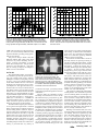
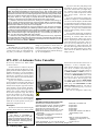
Product Review Column from QST Magazine
February 1996
Kenwood TS-870S MF/HF Transceiver
MFJ-9420 20-Meter SSB Travel Radio
JPS ANC-4 Antenna Noise Canceller
Copyright © 1996 by the American Radio Relay League Inc. All rights reserved.
Product Review
Edited by Rick Lindquist, KX4V • Assistant Technical Editor
Kenwood TS-870S MF/HF Transceiver
Reviewed by Larry Wolfgang, WR1B
Senior Assistant Technical Editor
With the introduction of the TS-870S,
Kenwood helps usher in a new era in Amateur Radio equipment design. As do the latest offerings from ICOM and Yaesu,
Kenwood’s newest MF/HF transceiver includes digital signal processing (DSP) at IF,
but with a difference. Kenwood’s competitors take the belt-and-suspenders approach
and couple crystal filters (both standard and
optional) with DSP on their latest radios,
but the TS-870S requires no additional crystal filters to supplement its DSP. It’s the first
radio in its class to make that claim.
To better understand how the TS-870S
implements DSP at HF, see the sidebar
“DSP in the Kenwood TS-870S.”
Features
The TS-870S’s attractive but no-nonsense front panel has the complement of
controls you would expect on any full-featured HF rig. But, not all of this radio’s
goodies are obvious at first glance. The
prominent main tuning knob has a softrubber grip that provides a comfortable feel
and a handy finger depression to spin up or
down the band. You can set the tuning steps
to 5 or 10 kHz per revolution. The FINE tuning button divides this value by 10 when
it is turned on, but you cannot display the
1 Hz units to go along with the fine tuning
steps. With the small tuning steps, the radio
sounds almost “analog” as you tune. None
of that digital warbling as the VFO changes
frequency!
Two groups of four controls apiece
(some of them concentric) flank the tuning
knob and give ready access to the most-used
functions. Better yet, the knobs and associated pushbuttons are substantial enough for
even the most fumble-fingered ops to get a
grip on them.
To the left of the main tuning knob, one
set of concentric controls adjusts the builtin electronic keyer speed and AGC attack
speed. Turning the AGC knob fully counterclockwise turns off the AGC; there is no
detent or other tactile response to let you
know when the AGC is off, so you’ll have to
look on the display for the red AGC legend
above the main frequency readout. Other
concentric controls in this group set the
speech processor and monitor volume levels, adjust CW, AM or FSK carrier level (or
SSB output with the speech processor on),
set VOX delay, and adjust microphone gain
and power output level.
Convenient pushbuttons just above
these knobs select the transmit metering
function (options are ALC, SWR, compression level and output power) and activate
the speech processor and monitor function.
The right-hand group of controls includes single-knob controls for RIT/XIT and
M.CH/VFO.CH (to change the memory channel or VFO channel), plus concentric controls to set AF or RF level and NB (noise
blanker) and SQL (squelch). A CLEAR
pushbutton quickly zeros the incremental
tuning. As you adjust the RIT, the main frequency display also changes to show the
actual receive frequency.
The display window conveys plenty of
information about the radio’s operating status. Is the AGC on? How about the speech
processor? The automatic antenna tuner?
All these questions and more are easily
answered at a glance. For example, one spot
in the display window shows DSP filter high
or low-frequency limits for phone modes,
filter bandwidth for FSK and filter center
frequency or bandwidth for CW. This information shares display space with RIT or
XIT tuning increment data, as well as with
the transmit frequency in split.
The left side of the display window is a
digital LCD representation of an analog
Bottom Line
The first DSP transceiver without
standard or optional narrow crystal IF
filters, the TS-870S offers fine receive
and transmit audio, noteworthy
selectivity and comfortable controls. A
snazzy computer-control program and
interface are standard.
meter—complete with an arc. In receive,
the top of the display is an S meter. In transmit, the same segments indicate output
power. In receive, the lower portion of the
display graphically indicates current filter
bandwidth and relative frequency shift.
This portion of the display lacks numbers,
so you can’t tell the exact filter settings. For
that information, you’ll have to look at the
right side of the display window (and you
may have to first turn the appropriate filterselect knob to activate the readout). In transmit, this same meter section displays SWR,
ALC or speech compression level. Turning
on the P HOLD menu selection holds peak
readings on both bar graphs for about 2.5
seconds.
Most users liked the display window
and its colorful legends. The bright, white
main display numerals are about a half-inch
high and easy to read. Red labels above
the frequency display indicate active functions, such as AGC , MONItor and speech
PROCessor. Yellow labels below the frequency display indicate the active mode.
One reviewer commented that the unlighted
LED segments remain distractingly visible
behind the display window lens. A darker
display-window lens could lesser the effect.
The ANT button selects between two
rear-panel antenna connectors. ATT UP and
DOWN buttons select either 0, 6, 12 or 18 dB
of receive attenuation. AIP (Advanced Intercept Point)—also available with the
touch of a button—helps to reduce intermodulation distortion by throttling back
the sensitivity. On a band crowded with
strong signals, you’ll likely want to leave
AIP on.
Getting Around with the ’870S
The ’870S has two VFOs plus 100
February 1996
71
Table 1
Kenwood TS-870, serial no. 70500128
Manufacturer’s Claimed Specifications
Frequency coverage: Receive, 100 kHz-30 MHz;
transmit, 1.8-2; 3.5-4; 7-7.3; 10.1-10.15; 14-14.35;
18.068-18.168; 21-21.45; 24.89 -24.99; 28-29.7 MHz.
Modes of operation: USB/LSB, CW, AM, FM, FSK
Power requirement: Receive, 2 A (no signal);
transmit, 20.5 A (max).
Receiver
SSB/CW sensitivity, bandwidth not specified,
10 dB (S+N)/N: 100-500 kHz, ≤1 µV; 500 kHz1.7 MHz, ≤4 µV; 1.7-24.5 MHz, ≤0.2 µV;
24.5-30 MHz, ≤0.13 µV.
AM sensitivity, 10 dB (S+N)/N, bandwidth not specified:
100-500 kHz, ≤2 µV; 0.5-1.7 MHz, ≤32 µV;
1.7-30 MHz, ≤2 µV.
FM sensitivity, 12 dB SINAD: 28-30 MHz, ≤0.25 µV.
Blocking dynamic range: Not specified.
Two-tone, third-order IMD dynamic range: Not specified.
Third-order input intercept: Not specified
Second-order intercept point: Not specified
FM adjacent channel rejection: Not specified
FM two-tone, third-order IMD dynamic range:
Not specified
S-meter sensitivity: Not specified
Squelch sensitivity: Not specified
Receiver audio output: 1.5 W at 10% THD into 8 Ω.
IF/audio response: Not specified.
Notch filter depth: 40 dB or more.
Spurious and image rejection: 80 dB or better.
IF rejection: 80 dB or better.
Measured in the ARRL Lab
Receive, 30 kHz to 30 MHz; transmit, as specified
As specified.
Receive, 2 A (no signal); transmit, 16.5 A (max), tested at 13.8 V.
Receiver Dynamic Testing
Minimum discernible signal (noise floor), 400 Hz WIDTH and 700 Hz SHIFT:
Preamp off
Preamp on
1.0 MHz
–108 dBm
–117 dBm
3.5 MHz
–131 dBm
–141 dBm
14 MHz
–129 dBm
–139 dBm
10 dB (S+N)/N, 1-kHz tone, 30% modulation, 6 kHz WIDTH:
Preamp off
Preamp on
1.0 MHz
35 µV (–76 dBm)
11 µV (–86 dBm)
3.8 MHz
2.3 µV (–100 dBm)
0.7 µV (–110 dBm)
For 12 dB SINAD, 14-kHz bandwidth:
Preamp off
Preamp on
29 MHz
0.9 µV (–108 dBm)
0.16 µV (–123 dBm)
Blocking dynamic range, 400 Hz WIDTH:
Preamp off
Preamp on
1.0 MHz
128 dB*
124 dB
3.5 MHz
127 dB*
124 dB
14 MHz
127 dB
123 dB
Two-tone, third-order IMD dynamic range, 400 Hz WIDTH :
Preamp off
Preamp on
1.0 MHz
83 dB
89 dB
3.5 MHz
99 dB
95 dB
14 MHz
97 dB
95 dB
Preamp off
Preamp on
1.0 MHz
+17 dBm
+17 dBm
3.5 MHz
+18 dBm
+2 dBm
14 MHz
+16 dBm
+4 dBm
Preamp off, +63 dBm; preamp on, +63 dBm.
88 dB at 20 kHz channel spacing (29 MHz).
Preamp off, 84 dB; preamp on, 79 dB at 20 kHz channel spacing (29 MHz).
S9 signal at 14 MHz: preamp off, 176 µV; preamp on, 50 µV.
At threshold, preamp on: FM, 0.03 µV; SSB, 1.3 µV.
2.4 W at 10% THD into 8 Ω.
Range at –6 dB points, (band width):
CW-N (400 Hz WIDTH , 700Hz SHIFT): 489-906 Hz (417 Hz);
CW-W (1000 Hz WIDTH , 700 Hz SHIFT ): 195-1203 Hz (1008 Hz);
USB-W ( LO=300 Hz, HI=3000 Hz): 230-2988 Hz (2758 Hz);
USB-N (LO =400 Hz, HI=1800 Hz): 391-1804 Hz (1413 Hz);
LSB-W (LO=300 Hz, HI=3000 Hz): 225-2967 Hz (2742 Hz);
LSB-N ( LO=400 Hz, HI=1800 Hz): 386-1798 Hz (1412 Hz).
As specified.
Preamp off, 98 dB; preamp on, 114 dB.
Preamp off, 115 dB; preamp on, 124 dB *.
Transmitter
Transmitter Dynamic Testing
Power output: SSB, CW, FSK, FM, 100 W (max),
CW, typically 113 W (max), <1 W (min); SSB, 118 W (max); <1 W (min),
20 W or less (min), continuously adjustable. AM, 25 W
varies slightly from band to band. AM, typically 24 W (max),
(max), 20 W or less (min), continuously adjustable.
<1 W (min). FM, typically 109 W (max), 9 W (min).
Spurious-signal and harmonic suppression: 60 dB or more. <60 dBc on all amateur bands. Meets FCC requirements for spectral purity.
SSB carrier suppression: 50 dB or more.
As specified.
Undesired sideband suppression: 50 dB or more.
As specified.
Third-order intermodulation distortion (IMD)
See Figure 1.
Expanded Product Review Test Results Report Available
products: Not specified.
The ARRL Laboratory offers a 30-page test result report on the
TS-870S that gives in-depth, detailed technical data on the
CW keyer speed range: 6-60 wpm.
As specified.
transceiver’s performance, outlines our test methods and helps
CW keying characteristics: Not specified.
See Figure 2.
you to interpret the numbers and graphs.
Transmit-receive turnaround time (PTT release to
S9 signal, 14 ms.
The report also includes spectral purity charts and receiver
50% audio output): Not specified.
sensitivity figures for all bands, all CW keying waveforms (not
just worst-case) and other facts to help you make an informed
Receive-transmit turnaround time (“tx delay”):
15 ms.
buying decision. The report even includes a summary of how
Composite transmitted noise: Not specified.
See Figure 3.
this radio stacks up with similar, previously tested units.
Size (height, width, depth): 4.7×13×13 inches; weight, ≈25 pounds.
Request the TS-870S Test Result Report from the ARRL
Technical Department at $7.50 for ARRL members and $12.50
Note: Dynamic range measurements were made at the ARRL Lab standard
for nonmembers, postpaid.
signal spacing of 20 kHz.
*Measurement was noise-limited at the value indicated.
72
February 1996
Figure 1—Worst-case spectral display of the TS-870S transmitter during two-tone intermodulation distortion (IMD) testing. The
third-order product is approximately 32 dB below PEP output,
and the fifth-order product is approximately 47 dB down.
The transceiver was being operated at 100 W PEP output at
14.2 MHz.
memory channels to make bandhopping and
frequency swapping a breeze. Unlike its
DSP competitors, the ICOM IC-775DSP or
the Yaesu FT-1000MP, the Kenwood
TS-870S does not have dual receive capability. You can transmit or receive on either
VFO or a memory channel, however. Press
the appropriate buttons in the RX and TX
columns to the right of the MODE buttons to
make a selection. A small LED lights in
each active button. A single memory channel can store separate transmit and receive
frequencies as well as mode information.
The inability to store filter settings in any
memory channel or band register was a
common complaint from reviewers, however. It seems odd in a radio this sophisticated that you can’t save a particular filter
setting with a certain frequency, but the
radio does remember what filter setting you
used last with each mode.
UP and DOWN buttons let you switch
bands in sequence or (with the 1MHZ button
activated) change frequency in 1-MHz steps
instead. Additionally, a ten-key, multifunction keypad allows direct frequency entry,
as well as storing memory data, selecting
scan functions and controlling the memory
keyer features. In VFO mode, you use the
M.CH/VFO.CH control to make large frequency excursions within a band in steps of
1, 5 or 10 kHz (menu settable).
For split-frequency operation you simply select one VFO (or memory channel)
for receive and the other VFO (or memory
channel) for transmit. Or you can program
a memory channel with both frequencies. If
you select different VFOs or memory data
for transmit and receive, you press and hold
the TF-SET button and use the main tuning
knob to set your transmit frequency.
One reviewer, who was used to the typical “split” button, found this a bit confusing. It does take getting used to. The
Figure 3—Worst-case spectral display of the TS-870S transmitter output during composite-noise testing. Power output is
100 W at 3.5 MHz. The carrier, off the left edge of the plot, is not
shown. This plot shows composite transmitted noise 2 to 22 kHz
from the carrier.
Figure 2—CW keying waveform for the
TS-870S in the semi-break-in mode
showing the first and second dits. The
upper trace is the actual key closure; the
lower trace is the RF envelope. Horizontal divisions are 10 ms. The transceiver
was being operated at 100 W output at
14.2 MHz.
right side of the display shows the transmit
frequency and the word SPLIT in small red
letters above it. There is no other indication. One contest group that used the radio
liked the fact that the ’870S displayed both
receive and transmit frequencies but felt it
was too easy to transmit on the wrong frequency.
Would You Like a Menu?
As we’ve suggested, all the ’870S’s features are not obvious at first glance. They’re
“hidden” within a menu system that our
review team found easy to use. The MENU
button provides access to dozens of userdefinable operating parameters, while the
M.CH/VFO.CH button selects the appropriate menu item. Two identical menu banks
(68 items each) let you define two completely different sets of operating conditions! This is useful for operators who want
the radio to perform one way for contesting
or DXing, but yet another for rag chewing
or operating digital modes. Ham families
using the same radio also might find the two
menu banks helpful.
You’ll want to have the manual at hand
as you make your menu selections—at least
at first—because the abbreviated word display can be a bit cryptic.
Among many other things, the menus let
you set or adjust AGC release times for
various modes, CW rise and decay times,
CW pitch, speech processor frequency response, panel brightness and various DSP
parameters.
DSP Goodies
Four pushbuttons along the upper righthand side of the front panel access the
radio’s DSP functions: AUTO NOTCH , BEAT
CANCEL, N.R. and TX EQ. The first three are
adaptive filters that can identify various
interfering signals or noise and modify their
filtering characteristics based on the particular noise or interference. (You can
switch between SPAC or Line Enhance
using a menu selection.) Auto notch only
works in SSB mode. This DSP filter identifies interfering tones in the receiver passband and attenuates them. Beat cancel
works in both SSB and AM, and is similar
to the auto notch filter, but can be more
effective for some types of tones. Some
reviewers lamented the lack of beat cancel
or manual notch for CW. ARRL Lab tests
found beat cancel was more effective
against multiple heterodynes than auto
notch, which only worked well against a
single heterodyne.
The DSP noise reduction system operates in any mode and effectively reduces
random background noise. It’s a bit like an
analog noise blanker (the TS-870S has one
of those, too), but it seems more effective
February 1996
73
than the typical noise blanker, which is best
at combating pulse-type noise. Some reviewers were disappointed the noise reduction was not front-panel adjustable, as it is
on competing transceivers as well as on
many add-on DSP boxes. A menu choice
lets you adjust the optimal correlation time
for best reception using NR.
The TX EQ button lets you apply highfrequency boost, bass boost or comb filtering to your transmitted phone signal according to a menu setting. Other menu settings
also let you tweak transmitted audio characteristics. In other words, you can tailor
your transmitted audio characteristics to
better match your voice, microphone frequency response and room acoustics. Reviewers got good audio signal reports during on-air testing. The transmitted audio did
not seem distorted even with 10 dB of
speech compression cranked in. As expected, the processor did add extra “punch”
to the signal.
Now to the heart of the matter, the two
small knobs— LO/WIDTH and HI/SHIFT —
that adjust the DSP filter settings. For phone
reception, the LO/WIDTH knob selects the
low-frequency cutoff and the HI/SHIFT knob
selects the high-frequency cutoff. On CW
and FSK the LO/WIDTH knob selects the
bandwidth, while the HI/SHIFT knob sets the
IF shift in CW. But watch out! Using the
menu, you can change CW pitch, or offset,
and if you select a narrow filter bandwidth
and adjust the IF shift, it’s possible to move
the received signal clean out of the passband! For example, if CW pitch is set to 500
Hz and the bandwidth is 100 Hz, with the IF
shift at 700 Hz you won’t be able to tune the
received signal for zero beat.
All reviewers liked the ability to easily
and quickly adjust DSP filter characteristics. Several commented on the operation
of these controls. Both give positive tactile
feedback—you can feel them “click” as you
rotate them, each click representing another
step in the DSP filtering. These steps seem
optimal for SSB, but, at times, too large for
other modes, where several reviewers
longed for finer control. For example, you
can select CW filter bandwidths of 1000,
600, 400, 200, 100 and even 50 Hz. (In FSK,
available bandwidths are 1500, 1000, 500
or 250 Hz.) At times one bandwidth seemed
too wide and the next one too narrow. While
running RTTY, for example, I would have
preferred a bandwidth somewhere between
500 and 250 Hz, especially while tuning for
stations. CW operators expressed similar
sentiments.
A peek at the Service Manual sheds
some light on what happens inside the radio
when you turn these knobs, and perhaps
offers an explanation for the “digital” steps.
The radio’s microprocessor selects IF filter
combinations based on the LO/WIDTH and
HI/SHIFT settings. In addition, the microprocessor sends control signals to the PLL
and DDS local oscillator circuits. By changing the LO frequency, the signal is shifted
74
February 1996
so the high and low-frequency edges of
the combined filter response reduce the effective bandwidth. Kenwood calls this technique “slope tuning.” Purely from an operating point of view, our reviewers would
have preferred to have the filters continuously tunable, in an “analog” fashion. But,
Kenwood’s implementation virtually demands a limited number of digital steps.
You may have to “twiddle” the two
knobs—and adjust the AGC time constant—to obtain the best performance. But,
this design means that strong signals close
to your desired receive frequency, especially on CW, may cause some blocking.
Turning on AIP and adding some attenuation may help.
I didn’t experience any interference that
couldn’t be acceptably reduced using the
TS-870S’s various adjustments. On the
other hand, tests in the ARRL Lab confirmed that strong, close-in signals could
produce troublesome IMD and degrade
dynamic range in the TS-870S.
Our in-house receiver guru, Dave
Newkirk, WJ1Z, asserts that Kenwood’s filtering scheme produces “the best receive
audio I’ve heard in an Amateur Radio product.” One reason, Dave goes on to say, is that
the TS-870S receiver has excellent immunity to in-passband IMD. Another reason,
he says, is that the TS-870S’s combination
of linked variable-IF-bandwidth and DSP IF
filtering “gives you maximal control over
how much of an incoming signal the radio
converts to audio: If you want, you can receive SSB with no detectable ‘other side of
zero beat’ response and an audio passband
that’s flat from nearly 0 to beyond 6 kHz.”
The TS-870S, Dave says, “lets you tailor your receive passband to match that of
transmitted signals, and the resulting highquality sound can be a revelation.” Dave
deplored the small size and poor audio fidelity of the built-in speaker. To take best
advantage of the received audio quality, a
good external speaker is a must.
Computer Control
Kenwood packages its Radio Control
Program software with the TS-870S. This
nifty Windows application lets you completely control the radio from your computer. A graphical representation of the radio is right there on the screen, and you can
push its buttons and twiddle its knobs with
your mouse or other pointing device. Clicking on the telegraph key graphic brings up
a text screen where you enter text and click
the key button to send it. You can even store
and load text files with “canned” messages.
It’s that simple!
Using the computer-radio interconnection via the built-in RS-232 port, you can
literally create your own user interface.
Don’t like the position of the main tuning
knob? No problem. Just move it! Prefer a
radio with a different shape or with customized controls? You’ve got it! You can
design, display and operate the radio of
your dreams.
It is fun to experiment with this software.
The familiar Windows drag and drop editing, “radio button” controls and pull-down
menus make the program easy to navigate.
In addition, many contesters like to use
contest software packages like CT or NA to
run their stations. It’s easy with the
TS-870S: just connect a 9-pin modem cable
and let your software do the rest.
CW Ops Only
CW ops will revel in the TS-870S’s
built-in, full-featured Logikey K-1 memory
keyer, controlled from the front panel. The
keyer was a favorite among the CW enthusiasts who tried the radio. (This is the
CMOS Super Keyer II as seen in November, 1990, QST and featured in recent ARRL
Handbooks.) It’s a lot of fun to play with,
and the Operator’s Manual devotes six
pages to it. The available speed range is
about 6 to 60 wpm, settable in ranges referenced on 20 wpm. The keyer includes four
message memories that can call each other
and that can send automatic serial numbers
for contesting.
Unless you’re using an amplifier, it’s
best to turn off the loud, clacking amplifier
switching/keying relay (a menu option).
The FULL/SEMI button selects full (QSK) or
semi-break-in CW operation.
Other Features
If you’d like, the TS-870S lets you program a set of “boundary” conditions for use
with its automatic mode. In this case, as you
tune the radio, say from the phone portion
of the band into the frequency range used
for digital modes and then into the CW region, the radio automatically selects the
appropriate mode. You can set up to 19 such
boundaries. Each mode change selects the
last-used filter setting for that mode. You
can’t store particular filter settings with the
boundaries, however.
The built-in automatic antenna tuner is
supposed to match impedances between 20
and 150 Ω. The tuner certainly does a good
job matching a resonant antenna beyond its
“normal” bandwidth, but it won’t work
miracles. I found it helpful for matching my
dipoles and triband Yagi over the entire
band. Near band edges, where the SWR
tends to climb, the tuner could provide a
near perfect match.
Another feature reviewers found especially useful was the “quick memory.” Say
you’re not having any luck trying to break
the DX pileup and want to come back a bit
later to try again. Just hit the M.IN button.
You can store up to five frequencies this
way. To recall them, hit the MR button. Turn
the M.CH/VFO.CH knob to step through the
five quick memory channels. Data move
through these channels in a first-in/first-out
fashion, so when you store a sixth frequency
the first one is pushed out of the register and
lost.
Using menu selections, you can repro-
DSP in the Kenwood TS-870S
Like the rest of the current crop of DSP-equipped amateur MF/HF transceivers,
the TS-870S performs digital signal processing at a low IF, about 11.3 kHz in
this case. On receive, the signal is first mixed to 73.05 MHz and passed through
the 15-kHz-wide “roofing” filter, then shifted down to 8.83 MHz to pass through a
3 or 6-kHz filter (or through no filter in FM). The signal is then shifted to 455 kHz,
where it passes through a 3, 6 or 15-kHz filter. Finally, the signal is mixed down to
11.3 kHz and applied to the DSP’s analog-to-digital converter.
The various oscillators that set the mixing frequencies are all digitally controlled,
and that turns out to be important. The TS-870S uses a time-honored technique to
achieve adjustable bandwidth and IF shift by varying these oscillator frequencies
so that one side of the receiver passband is set by the 8.83-MHz filter and the other
side by the 455-kHz filter. The resulting band-limited signal then is demodulated by
the DSP. It is also bandpass filtered by the DSP, and the DSP generates the AGC
voltage. Since both the oscillators used for mixing and the DSP unit are digitally
controllable, the TS-870S can adjust the analog passband and the digital passband
in tandem.
Consider what this means. If the TS-870S relied only on DSP to narrow the
receiver’s passband, signals outside the DSP filter but inside the analog passband
would pound away at the IF circuitry, possibly causing gain compression (blocking)
and/or IMD generation. On the other hand, if the TS-870S relied only on the analog
filters to set the passband, strong-signal performance wouldn’t be as bad, but you
wouldn’t have the advantage of the “brick-wall” shape of a DSP filter’s frequency
response. But the TS-870S uses both kinds of filtering. That means the receiver’s
ultimate passband is set by the DSP filters, but signals outside the DSP filter
passband are attenuated by the analog filters.
The results of this tradeoff are particularly noticeable in CW. To achieve a typical
CW passband of 400 or 600 Hz, the analog filters are shifted so that their passbands overlap only by the desired amount. But between the filters, in the mix down
to 455 kHz, a full 3-kHz-wide swath of signals—the signals that pass through the
8.83-MHz filter—is present. This means that signals within this 3-kHz-wide band,
but outside of the desired passband, may cause blocking or generate IMD. (For an
explanation of this effect, see “Putting Variable-Bandwidth Tuning Back into LateModel ICOM IC-751A Transceivers,” Hints and Kinks, April, 1991, QST .) We found
this to be the case with the TS-870S. For example, blocking dynamic range
degrades by 10 dB or so when a signal appears inside the 8.83-MHz filter, as
compared to the same signal appearing outside that filter. Older, non-DSP Kenwood
designs allowed for inclusion of narrow crystal filters—typically 500-Hz-wide—in
the IF stages. These created a narrow passband with a good shape factor, which
simply isn’t the case when using one IF to set the high edge of the passband and
the other IF to set the low edge. The DSP in the TS-870S takes care of the shape
factor, but the lack of a narrow crystal filter means that a wide-bandwidth signal is
always present in the 8.83-MHz IF stages, no matter what LO/SHIFT or HI/WIDTH
settings you use.
The radio uses two Motorola DSP56002 DSP chips, which represent a lot of
processing capability. This allows the demodulation and filtering functions to be
combined with adaptive filters for noise reduction and automatic notching.
In transmit, the TS-870S uses the DSP system to generate the modulated signal,
which is then mixed up to the output frequency through several stages. The DSP
also processes the transmitted audio, including speech compression and VOX, and
generates the CW sidetone and the radio’s various control beeps, a nice economy
of circuitry. (Why not use the DSP instead of building a beep oscillator?)
The TS-870S does a good job of integrating DSP technology into an HF
transceiver. While any technology can be improved, the scheme used by Kenwood
takes good advantage of the possibilities of digital signal processing. If provision
were made for optional 500-Hz crystal filters, the combination of analog and DSP
performance would be nearly ideal.— Jon Bloom, KE3Z
gram four front-panel buttons ( ENTER,
TF-SET, 1MHz and FINE ) to handle other
functions you might find more useful. Or,
you can disable them altogether if you want.
The TS-870S Instruction Manual is 100plus pages chock full of clearly written and
easy-to-understand information and operating tips. It even includes a brief DSP tutorial. Plenty of diagrams help you identify
various controls and connections. Sche-
matic diagrams are on two 23×32 inch
folded sheets, and there’s a smaller block
diagram.
No one on the review team even mentioned cooling fan noise with the TS-870.
Indeed, it’s hard to tell when it’s running.
The “Dark” Side
There’s nothing particularly remarkable
about the radio’s rear panel, except a lack of
clutter. There are two antenna jacks, plus
connections for a keyer paddle, a straight
key or external keying device, external
speaker, amplifier connections, accessory
connector for a multimode communications
processor (MCP) for RTTY, packet and
other digital modes and a 9-pin RS-232
computer interface connector. I was glad to
see a ground lug with a wing nut and washers rather than a “push-in terminal” for a
solid wire that some radios call a ground
connection. A phono jack provides the 8.83MHz IF signal for connection to a station
monitor.
Fortunately, Kenwood supplies the 13pin DIN plug accessory connector for an
MCP, since it would no doubt be difficult to
find one otherwise. Soldering connections
to this plug is no picnic, however. The spacing between pins is one-tenth of an inch, so
solder bridges and stray wire strand problems happen easily.
You’d think the phono jack labeled EXT
RX ANT is for an external receive antenna,
but you’d be wrong! This jack lets you connect a second receiver to the ’870S.
Kenwood concedes that connecting a separate receive antenna to the TS-870S, such
as a Beverage for 80 or 160 meters, is not
possible without internal modifications.
The TS-870S does not have a built in AC
power supply. It needs 13.8 V dc at 20.5 A.
If you don’t already own a suitable supply,
add that cost to the price of the radio!
The Complete Radio?
I have yet to find the “perfect radio” at
a price I could afford. We could consider
the TS-870S to be the “complete radio,”
however. Except for the required power
supply, the TS-870S is ready to go as it
comes out of the box. It doesn’t need additional IF filters, an external audio DSP unit
or an external memory keyer. Available
matching accessories fall under the heading of nice to have rather than need to have.
Perhaps Dave Newkirk summed it up
best: “Nits aside, the TS-870S is a great beginning for something new in Amateur Radio: Radios with IF DSP that do IF filtering—IF DSP that’s teamed with AGC
performance that needs no apology and that
produces the stellar receive audio today’s
best analog designs can only approximate.”
Thanks to these hams who contributed
operating impressions and comments for
this review: Rick Lindquist, KX4V; Dave
Newkirk, WJ1Z; Glenn Swanson, KB1GW;
Jon Bloom, KE3Z; Mike Gruber, WA1SVF;
Tom Frenaye, K1KI (and his contest team)
and Emil Pocock, W3EP.
Manufacturer’s suggested retail prices:
TS-870S, $3199.95, MC-90 desktop microphone, $269.95; PS-52 heavy-duty power
supply, $309.95, SP-31 external speaker,
$99.95. Manufacturer: Kenwood Communications Corp, P.O. Box 22745, Long
Beach, CA 90801-5745, tel 310-639-5300.
February 1996
75
MFJ-9420 20-Meter SSB Travel Radio
Reviewed by Steve Ford, WB8IMY
Managing Editor
I used to think that operating SSB on the
HF bands with only 10 W was a fool’s game.
As far as I was concerned, low-power hamming was strictly the province of CW lovers. After all, the ability of a CW signal to
be heard under virtually any condition
makes it an ideal mode for low-power. Attempting the same thing with an SSB signal
(with its highly variable audio characteristics and broad-as-a-barn bandwidth),
seemed like a grand waste of time.
It’s funny how we carry certain assumptions for years without really putting them
to the test. I was due for a wake-up call—in
the form of the MFJ-9420 transceiver.
Back to Basics
It’s difficult to find an SSB transceiver
that’s more basic than the MFJ-9420. The
tiny radio features only four controls: VFO,
POWER ON/OFF , VOLUME , and TUNE ON/
OFF . (The TUNE ON/OFF button lets you put
out a reduced-power carrier for an external
antenna tuner.) A five-pin DIN-type microphone connector, a backlighted analog S
meter and two LEDs round out the collection. That’s it! On the rear panel you find an
SO-239 antenna jack, dc power connector,
microphone level control and—if you install
the MFJ-415 CW adapter—a button to enable CW operating and a key jack. An internal speaker graces the top of the cabinet.
The MFJ-9420 receiver is a single-conversion superheterodyne. A four-pole
bandpass filter at the input functions as an
effective preselector for 20-meter signals.
The active mixer stage converts the signals
to the 10-MHz IF. From there, a crystal ladder filter sets the IF bandwidth before the
signals are applied to a single-chip IF amplifier. Another IC acts as the product detector, and its output drives yet another chip
which functions as an audio preamp and
filter. AGC is audio-derived and can be
adjusted internally. The final audio amp
drives the speaker directly, providing
plenty of room-filling volume, although the
output as measured by the ARRL Lab fell a
tad short of the specified 1 W or so.
In the transmitter, a microphone speech
amplifier drives a balanced modulator, and
a filter then removes the lower sideband and
carrier. (The MFJ-9420 operates in upper
sideband only.) After undergoing a healthy
amount of dynamic compression (more
about this later), the USB signal is routed to
the transmitter mixer. RF predriver, driver
and final output stages follow.
The MFJ-9420 is designed to generate
Bottom Line
Impressive performance in an
economical, go-anywhere low-power
transceiver that’s loads of fun to use.
76
February 1996
about 10 W “average speech” output. My
unit cranked out approximately 8 W. This is
not QRP by strict definition (5 W PEP or
less). Sticklers can crank down the microphone level to achieve true QRP. That’s just
what I did during the 1995 November
Sweepstakes—with interesting results.
(See the sidebar, “Phone Sweepstakes
1995—The 30-Minute Sprint.”)
Power requirements are simple: 12 V at
2 A. I used a Radio Shack regulated dc supply
and it didn’t even break a sweat. You could
also use a rechargeable gel-cell battery.
MFJ-415 CW Adapter
Unwilling to explore 20 meters with one
hand behind my back, I decided to add the
MFJ-415 CW adapter. The adapter is a
small L-shaped circuit board that installs
atop the primary transceiver board. Installation is straightforward and takes less than
a half-hour. You secure the board on standoff posts and mate two small connectors.
The adapter expands frequency coverage down to 14.0 MHz simply by adding
capacitance to the VFO tank circuit. When
you key the transceiver, the adapter unbalances the balanced modulator, resulting in
a carrier on the desired frequency. Nothing
too complicated about that. The keying delay and sidetone volume are adjustable
through potentiometers on the adapter
board. These pots are not accessible without removing the cover, however.
As you might suspect, the adapter is a bit
of a compromise. The offset is fixed at
roughly 700 Hz at the factory. To change it,
you need a frequency counter or a generalcoverage receiver. The 700-Hz offset was
fine for me, but it might be unacceptable to
other operators. IF bandwidth is the same as
for SSB.
The MFJ-415 adapter does not provide
full break-in (QSK). In addition, keying was
somewhat harsh. The roughness was noticeable but, in my opinion, not objectionable.
However, a CW purist might cringe at every dit and dah. Also, we discovered during
Table 2
MFJ-9420 “Travel Radio” 20-Meter SSB Transceiver
Manufacturer’s Claimed Specifications
Frequency coverage: Receive, 14.150-14.350 MHz,
SSB; 14.0-14.100, CW; transmit, not specified.
Modes of operation: USB and CW (with CW adapter)
Power requirement: Receive, 100 mA (typical max);
transmit, 2.2 A (max) at 13.8 V.
Measured in the ARRL Lab
Receive and transmit, 14.15314.344 MHz, SSB; 14.0-14.145 MHz, CW.
As specified.
Receive, 109 mA; transmit 1.8 A, tested
at 13.8 V.
Receiver
SSB/CW sensitivity (bandwidth not specified,
12 dB S/N): <0.5 µV (–113 dBm).
Blocking dynamic range: Not specified.
Two-tone, third-order IMD dynamic range:
Third-order intercept point: Not specified.
Second-order intercept point:
S-meter sensitivity: Not specified.
Receiver audio output: >1 W at 10% THD into 8 Ω.
Spurious and image rejection: Not specified.
Receiver Dynamic Testing
Minimum discernible signal 0.6 µV
(–131 dBm).
103 dB.
82 dB.
–8 dBm.
+77 dBm.
S9 signal, 115 µV.
0.6 W at 10% THD into 8 Ω.
IF rejection 55 dB; image rejection 99 dB.
Transmitter
Power output: CW, 8-10 W; SSB, 10 W PEP.
Spurious-signal and harmonic suppression:
Not specified.
SSB carrier suppression: Not specified.
Undesired sideband suppression: Not specified
Third-order intermodulation distortion products:
Not specified.
CW keying characteristics: Not specified.
Transmit-receive turnaround time (PTT release to
50% audio output): Not specified.
Receive-transmit turnaround time (“tx delay”):
Composite transmitted noise: Not specified
Size (height, width, depth): 2.5×6.5×6 inches; weight,
Transmitter Dynamic Testing
CW and SSB, ≈8 W.
45 dB. Meets FCC requirements for
spectral purity.
≈40 dB.
46 dB.
See Figure 4
See Figure 5
S9 signal, ≈78 ms.
≈18 ms.
See Figure 6
≈2 lb.
Figure 4—Spectral display of the MFJ-9420 transmitter during
two-tone intermodulation distortion (IMD) testing. Third-order
product is approximately 19 dB below PEP output, and the fifthorder product is approximately 28 dB down. The transceiver was
being operated at approximately 8 W PEP output at 14.2 MHz.
Figure 6—Spectral display of the MFJ-9420 transmitter output
during composite-noise testing. Power output is approximately
8 W at 14.2 MHz. The carrier, off the left edge of the plot, is not
shown. This plot shows composite transmitted noise 2 to 22 kHz
from the carrier.
ARRL Lab tests that even a high resistance
(1 MΩ or so) across the key terminals would
key the transmitter, possibly posing a problem for some keyers.
The point to keep in mind is that the
MFJ-415 adapter adds value to the 9420
transceiver by almost doubling the frequency coverage and adding a second
mode. The casual operator—the person this
transceiver was designed for—will probably be willing to forgive the adapter’s
faults in view of its benefits.
On The Air
They call the MFJ-9420 a “travel radio,”
so I decided to get into the spirit of the design. (No, I didn’t pack it into a suitcase,
although I could have, with plenty of room
to spare.) I cut a wire dipole antenna and
center fed it with RG-58 coax. One end of
the dipole was about 40 feet up in a backyard maple tree. The opposite end was anchored to the roof of my tool shed, about 8
feet off the ground. I was careful to trim the
antenna for a 1:1 SWR, because the 9420
design does not include foldback circuitry
to protect the RF output transistor, an MRF477 that MFJ describes as “bullet-proof”
(MFJ says it “tolerates a 3:1 VSWR and
accidental feedline shorts or opens”). Besides, at such low power levels you can’t
afford to waste power in the feed line.
The MFJ-9420 occupied a place of honor
on our guest room night stand. I assumed
that it would end up in a similar location in
a hotel, fishing cabin or wherever. My first
surprise came when I stretched out on the
bed and switched on the radio. I expected
muddy audio and a few signals here and
there. Not so! The 9420’s receiver was remarkably sensitive and selective. I spent
considerable time listening to everything
from DX pileups to traffic nets. The VFO is
touchy, so you must tune very slowly. If
Figure 5—CW keying waveform for the
MFJ-9420 in the semi-break-in mode
showing the first and second dits. The
upper trace is the actual key closure; the
lower trace is the RF envelope. Horizontal
divisions are 10 ms. The transceiver was
being operated at approximately 8 W output
at 14.2 MHz. Note the significant shortening
and slower rise time of the first dit.
you become too eager, you’ll find yourself
zipping through a dozen signals in one twist
of the knob.
Receive audio was abundant, but that
advantage soon turned into a curse. If the
MFJ-9420 is truly a go-anywhere rig, how
do you prevent your fellow travelers from
being inundated by a symphony of signals?
(I often have a sleeping toddler in the next
room. If I awaken her, it’s my duty to get
her back to sleep.) The obvious answer was
headphones, but I quickly discovered that
the 9420 lacks a headphone jack! I grabbed
a jack from my junk box and improvised,
eventually creating a pig-tail assembly that
protruded from the back panel. (I couldn’t
bring myself to drill a hole in a new radio.)
After assuming a comfortable position
on the guest bed once again, I began searching for phone contacts. I answered a CQ
from a ham in Scotland who gave me a 56
report. Impressive! When I told him what I
was running, I could hear the astonishment
in his voice. As I once had, he simply had
taken it on faith that operating sideband
QRP was next to impossible.
Part of the secret of the 9420’s success is
the hefty amount of speech processing it
uses. By watching the output meter, I could
tell that my average power level was barely
fluctuating. I asked the fellow how I
sounded, and he simply described the audio
as “punchy.” At least it didn’t sound as
though the rig was trying to suck the room
into the microphone along with my voice!
I enjoyed similar conversations (and signal reports) with other hams in the US,
South America and Europe. As long as the
band remained stable and interfering stations kept their distance, I could talk as long
as I liked. Generally speaking, I was able to
work any station I could receive at moderate strength (S5 or greater on the 9420’s
meter). I even managed to bag some of the
weaker ones, but with difficulty.
CW operating with the MFJ-9420 takes
a little practice. You need time to perfect
your zero-beating skills, for example. You
don’t have the luxury of an RIT control to
assist. And don’t forget that the offset is
adjustable only by recalibrating the adapter.
You also must acclimate yourself to the
clattering relay. Hams accustomed to silent
T/R switching may find themselves distracted at first. But after a few minutes on
the air, I hardly noticed the noise.
Running CW with the 9420 was every
bit as enjoyable as operating phone. During
one Sunday afternoon I prowled up and
down the band making contact after contact. I even managed to fight my way
through a small pileup and work a station in
Morocco. The only annoyance was the inability to narrow the receive bandwidth. An
audio filter would be a big help.
February 1996
77
Phone Sweepstakes 1995—The 30-Minute Sprint
If you’re going to put a new transceiver through a baptism of pure hellfire, the
ARRL November Sweepstakes is the best time to do it. This contest draws a tidal
wave of phone and CW operators on two separate weekends. Unfortunately, family
activities knocked me out of the CW slugfest (another operator easily worked a half
dozen or so stations with the 9420, however), and I could only spare a half hour for
the phone brawl. If I was going to properly abuse the MFJ-9420—figuratively
speaking—it would have to be within the first 30 minutes of the contest.
I jumped in with both feet at 2100 UTC, starting at 14.150 MHz and working my
way up. I began hunting and pouncing on the strongest stations, and this strategy
paid off right away. The big guns didn’t always answer my first call, but I usually
attracted their attention by my third or fourth appeal.
Despite the RF pandemonium, everyone seemed to copy me well. The 9420’s
receiver also did an adequate job of distilling relative order from chaos. A number
of stations expressed amazement when I told them I was QRP (Using the microphone
gain control, I had reduced the output to slightly less than 5 W PEP— true QRP.) One
fellow in Minnesota thought I was pulling his leg: “You’re kicking my meter up to
S 9. You can’t be running QRP with just a dipole!”
I doubt that I was pushing many receiver meters beyond S 5, but my signal was
strong enough that I rarely had to repeat an exchange. I shut down at 2130 UTC with
32 contacts in the log—slightly more than one contact per minute. Not bad for a radio
that you can hold in one hand!—WB8IMY
Conclusion
The MFJ-9420 is a terrific little transceiver for casual 20-meter operating. With
a small power supply or rechargeable battery pack, you can take it anywhere. Al-
though it’s promoted as a travel radio, the
9420 is fine for home use—especially for a
low-profile station. (It also was a pleasure
to work 20-meter phone without tearing up
my TV and telephones!)
You won’t bust many DX pileups with
the 9420 nor win any contests, but you will
work more stations than you might imagine—and have a heck of a good time while
you’re at it. (I wonder if anyone has earned
their phone DXCC with this radio?
Hmmm…)
If you’re at all inclined to operate CW,
the MFJ-415 adapter is worth the additional
cost. Even with the adapter, the MFJ-9420
is still within most hams’ budgets. In fact,
the MFJ-9420 could be an excellent starter
radio for new hams licensed at General class
or higher—as long as they understand the
nature of QRP operating and have realistic
expectations.
As I’ve already mentioned, a headphone
jack would be a welcome addition. For CW
operating, an external audio filter also
would substantially enhance the performance. Nitpicking aside, the MFJ-9420 is
a fun radio that has more than a few surprises in store for jaded hams such as myself! Manufacturer: MFJ Enterprises, PO
Box 494, Mississippi State, MS 39762, tel
800-647-1800. Suggested list prices: MFJ9420 transceiver, $229.95; MFJ-415 CW
adapter, $39.95.
JPS ANC-4 Antenna Noise Canceller
Reviewed by Emil Pocock, W3EP, ARRL
Technical Advisor
Voodoo electronics! That was my first
reaction after hearing the JPS ANC-4 completely eliminate loud computer hash in the
middle of 40 meters. It is also remarkably
effective in reducing the radio-frequency
interference generated by nearby power
lines, electric motors, televisions and many
home electronic devices.
Typical noise blankers and limiters often are ineffective in dealing with many of
these problems. Even when they do reduce
interference from pulse-type radio sources,
noise blankers create another difficulty.
Strong adjacent signals can trigger the automatic gain control, effectively reducing
the receiver’s dynamic range. The ANC-4
avoids this problem by removing many
types of local noise before the offending
signals enter the receiver. Desired signals
previously buried in the noise magically
stand out in a much-quieter receiver passband when using the ANC-4!
Description
The ANC-4 is enclosed in a rather weighty
two-piece black steel box. It easily installs
Bottom Line
The ANC-4 is remarkable in
reducing local RF noise on a wide
range of frequencies and modes. To
defeat local noise before it reaches
your transceiver’s antenna jack, the
ANC-4 is hard to beat.
78
February 1996
between the station antenna and receiver or
transceiver. A short, collapsible whip—
which mounts through a hole on top of the
unit—serves as a built-in noise-sensing antenna. On the rear apron are UHF connectors
for MAIN ANTENNA and RADIO (receiver or
transceiver), a phono jack for an optional (ie,
external) wire NOISE ANTENNA , and a coaxial
dc power jack. Any 12-V source delivering
up to 150 mA will do. JPS can supply a 120V ac adapter. The adjustable NOISE PHASE
and NOISE GAIN controls are on the front
panel, along with PHASE RANGE and FREQUENCY RANGE pushbuttons. The ANC-4
has a built-in RF-sensing relay, so it can be
used with a transceiver.
The ANC-4 is designed to reduce only
Table 3
JPS ANC-4 Antenna Noise Canceller
Manufacturers Claimed Specifications
Operating frequency range: 100 kHz to 80 MHz.
Noise cancellation: 40 dB or greater typical.
Signal loss from main antenna: 6 dB.
Maximum RF input to main antenna: 3 V rms.
Maximum RF transmit power through unit:
150 W PEP.
Time to switch to bypass when transmit RF
is detected: 7 ms typical.
Time to return to receive when transmit RF
is removed: 500 ms typical.
Measured in the ARRL Lab
As specified.
As specified.
As specified.
As specified.
As specified. Tested at 14 MHz for
approximately 5 mins.
6 ms.
≈600 ms. (JPS new includes a
resistor to cut hang time to 7 ms,
if desired.)
Power requirements: 11 to 16 V dc at 150 mA.
75 mA at 13.8 V.
Size (height, width, depth): 1.7×6×4.3 inches. Weight: 2 lb.
locally generated RF noise and does little
to reduce noise from distant sources, including static. The unit performs its magic
by comparing two signal sources. The first,
originating primarily via the main antenna,
contains the desired signals plus the unwanted RF noise. The second, arriving via
the noise-sensing antenna, consists mostly
of the undesired RF noise, which is amplified and passed through an adjustable
phase-shift network. You set the NOISE
GAIN control so noise from the noise antenna just equals noise from the main antenna. Then, you adjust the phase-shift
network with the NOISE PHASE control
until the two noise sources are 180° out of
phase. The two signals enter a hybrid combiner, where the noise components cancel
each other. The desired signal—coming
almost exclusively from the main antenna—passes through the combiner with
some loss but is otherwise unaffected.
Performance
Adjusting the NOISE PHASE and NOISE
controls to achieve complete noise
cancellation was sometimes tricky, especially above 15 MHz. The two controls interact to some extent, but the general idea is
to increase the NOISE GAIN until some perceptible change is noted, then to vary the
NOISE PHASE knob until you null the noise.
Changing the frequency and phase range
switches sometimes helped, but there was
no way to know in advance what settings
would achieve optimal results. Once found,
further adjustment was not needed while
tuning as much as several hundred kilohertz
from the initial frequency.
The ANC-4 did a remarkable job of
eliminating the simultaneous noise from my
computer, television, and telephone answering machine, which are scattered about
the house. I brought my especially noisy
computer down to the shack, as if for contest logging or to run a packet station. The
ANC-4 had no trouble knocking out all
traces of the S9 noise on any band. Below
10 MHz, the insertion loss was hardly perceptible. However, at 50 MHz—where CW
or SSB signals might be very weak—the
insertion loss was noticeable. Even so, being able to take out 50 dB of local noise
generally justified the one S-unit or so loss
of signal strength.
The top-mounted whip prevent you from
putting the unit below a shelf or other overhang. I found a wire noise antenna much
more flexible, since its length and placeGAIN
ment often made all the difference to good
performance, especially at higher frequencies. I eventually settled on a 10-foot wire
stretched across the ceiling in the basement
shack as optimal for 28 and 50 MHz, but the
noise antenna size and placement will vary
with circumstances. The ANC-4 works best
when the noise antenna is close to the noise
source. Lab tests showed the unit especially
needed a strong noise signal above 30 MHz
to effectively cancel it. So, if the problem is
a furnace blower, it may help to place the
antenna near the furnace and connect it to
the ANC-4 via coaxial cable. Its effectiveness against power line noise may be increased by placing several feet of noise
antenna parallel to some house wiring or
even laying the noise antenna on the ground
beneath the errant power lines. The ANC-4
also can be used in a mobile setup. In that
case, the manual suggests routing a wire
noise antenna into the engine compartment
to insure good pickup of offending ignition
and alternator noise.
Other Uses
The ANC-4 also can serve as an “active
antenna.” In that mode, no antenna is connected to the main antenna jack. Instead,
the top-mounted whip (or a short wire)
serves as the main receiving antenna, and
the NOISE GAIN control adjusts the amplification of the received signals. With some
experimentation, the ANC-4 also can be
used for diversity reception. You connect a
second antenna of opposite polarization or
separated by several wavelengths from the
main to the noise antenna jack. Then, you
adjust the controls to combine signals from
both antennas so they are in phase. The
ANC-4 also can be used to create a receiving antenna system with a high front-toback ratio. Such a system requires a second
antenna that’s similar to the main one, but
separated from it by at least half a wavelength. In this case, you use the NOISE
PHASE adjustment to null signals arriving
from the unwanted direction.
The controls and noise antenna placement can be critical, but once you find optimal operating conditions, the unit generally requires no further adjustment within a
given amateur band. Its use does not affect
the dynamic range or other performance
features of the main receiver. Thanks to
Charles Michaels, W7XC, and Rick
Lindquist, KX4V, for contributing to this
review.
Manufacturers suggested retail price:
$175. Manufacturer: JPS Communications,
PO Box 97757, Raleigh, NC 27624; tel,
919-790-1048; fax, 919-790-1456.
SOLICITATION FOR PRODUCT
REVIEW EQUIPMENT BIDS
[In order to present the most objective reviews, ARRL purchases equipment off the
shelf from dealers. ARRL receives no remuneration from anyone involved with the sale or
manufacture of items presented in the Product Review or New Products columns.—Ed. ]
The ARRL-purchased Product Review
equipment listed below is for sale to the highest bidder. Prices quoted are minimum acceptable bids, and are discounted from the purchase
prices. All equipment is sold without warranty.
Alinco DX-70T MF/HF/VHF transceiver
(see Product Review, December 1995
QST). Minimum bid: $759.
ICOM IC-775DSP MF/HF transceiver with
optional filters FL-222, FL-223 and FL-102
(sold as a package only; see Product Review, January 1996 QST). Minimum bid:
$2855.
MFJ-411 Pocket Morse Tutor (see Product
Review, December 1995 QST). Minimum
bid: $50.
morsix Codeman mt-5 Morse code trainer
(see Product Review, December 1995
QST). Minimum bid: $102.
Sealed bids must be submitted by mail and
must be postmarked on or before March 1,
1995. Bids postmarked after the closing date
will not be considered. Bids will be opened
seven days after the closing postmark date. In
the case of equal high bids, the high bid bearing
the earliest postmark will be declared the successful bidder.
In your bid, clearly identify the item you
are bidding on, using the manufacturer’s name
and model number, or other identification
number, if specified. Each item requires a
separate bid and envelope. Shipping charges
will be paid by ARRL. Please include a daytime telephone number. The successful bidder
will be advised by telephone with a confirmation by mail. No other notifications will be
made, and no information will be given to anyone other than successful bidders regarding
final price or identity of the successful bidder.
If you include a self-addressed, stamped postcard with your bid and you are not the high
bidder on that item, we will return the postcard
to you when the unit has been shipped to the
successful bidder.
Please send bids to Bob Boucher, Product
Review Bids, ARRL, 225 Main St, Newington,
CT 06111-1494.
February 1996
79