1
OWNERS AND SERVICE MANUAL
COPYRIGHT 1992 INNOVATIVE CONCEPTS IN ENTERTAIINMENT INC.
LICENSED FROM C.L. TECHNOLOGY
TABLE OF CONTENl-S
INTRODUCT’ION
. . . . . . ..*................*............................. PAGE 3
. Game Features
Game Play
l
ASSEMBLY . . . . . . . . . . . . . . . . . . . . . . ...*.....
. . . . . . . . . . . . . . . . . . . . . . . . . ...*.....
Set-up
. Customizing Your Game
Message Center
. Self Test
Credit Cost Display
. Game Testing
Electronic Game Counter
PAGE 5
l
l
l
l
MAINTENANCE b TROUBLE SHOOTING . . . . . . . . . . . . . . . . . PAGE 11
. Quick Trouble shooting
. Operational Background
. Mechanical Repair
Maintenance
Electronic & Electrical Repair
l
l
OPTIONAL ACCESSORIES . ..*..........*....................**.... PAGE 21
*Ticket Dispenser
Card Dispenser
. Dollar Bill Validator
l
LISTINGS . . . . . . . . . . . . . . . . . . . . . . . . . . . . . . . . . . . . . . . . . . . . . . . . . . . . . . . . . . . . .
..~.... PAGE 23
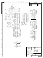
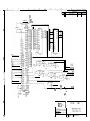
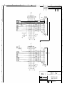
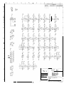
SCHEMATICS . . . . . . . . . . . . . . . . . . . . . ..*....................................PAGE 25
MONITOR
SERVICE MANUAL . . . . . . . . . . . . . . . . . . . . . . . . . . . . . . . . . . . PAGE 41
DIAGRAMS Q ILLUSTRATIONS . . . . . . . . . . . . . . . . . . . . . . . . .
..-<a.... PAGE 65
WARRANTY INFORMATION . . . . . . . . . . . . . . . . . . . . . . . . . . . . . .
..s....* PAGE 69
PAGE 1
INTRODUCTION
GAME FEATURES
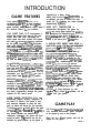
FULL COURT FRENZTM (F.C.F.) is a
revolutionary concelpt in Coin 0 rated
basketball games. YIDU will see trat this
supported by a heavy du rechargeable
battery with a built in ret x arging circuit As
an operator you can of course turn this
option off, by disabling the alarm through
programming optlons.
game includes many features which make it HEAW DUTY CONSTRUCTION is
the obvious choice hx your location.
incorporated throughout the game by
using only heavy gage metals and plastics.
FULL COURT PLAY. F.C.F. incorporates a
The oame can be assembled and
basket that rotates from side to side and
di&embled many times wiithout any
moves back and forth. Depending on
harm to the game. You w!ii appreciate this
which game has been chosen, the basket
feature if you move your games often.
will move t:, various DJFFERENT positions
as the game progresses. This movement
A CUSTOM OVER UNDER CASH DOOR is
adds many shootinc angles to challenge
the player. The met anism tha: 0 crates
le that has a stat
this unique capability
-I is YCI~ reiia E le and
s!mple in design. Cut steel gears make the
combination. This adds a great deal of
drive mechan!sm aimost irnrncne to wear.
secun~ to the gaine while keeping
r;nd a built in high tach muiri-plate clutch
maintenancr s!mple. An optional custom
absorbs any Cis;ia:; hi cm 52 genera&,5
security hasp system is available for the
by even the most &Iiber&a abuse.
front ~anei on this oame. “lClATE-LOCK”
conn&tors are usedthroughout the game
A 19” COLOR M8NiiTOR !S ~jssd to display
for their rucoed rellabllitv as well as
ail scoring and st&istical Infc:,rmation, and
making it vGuaRy impos&ie to connect
gives the game a look no orhe: basketball
hamessicg thz wrong wa . Heavy duty
can claim. A co!orful attract mode rounds
optical s~~ixoif are used t.&oughout
out the look of the mon!tor, and
D!gltaf sound effects are used or optimum
informative game play dicetions are just 3
dapendabiliQ.
CXler twenty sound effects
push button away for the> gam? players.
are into
rated Into the sound effect
circuhts. re game electronics have been
MESSAGE CENTPJX. A scroiling message
highly integrated into the Main P.C. Board
display option is !ncorpo,zti?d to a!low the
assembly,
makin it easy to r-e ir games. .
location or operator to advsrt4s.e or display
Ths qame has a iG II feature sertest svstem
messages on the dispta monltor. These
to mike trouble shooting easier.
’
messages are dlsplaye claiong the bottom
of the screen during the attract mode. They OPTIONS - A ticket dispenser or card
are easily programmed through the push
dis nwr and a dollar bill validator, can be
buttons on the control panel.
orr
ered with your game.
SUPER TAMPER PROTECTION. F.C.F. has
exceptional tamper circuitry integrated to
the main P.C. Board. If the game is over,
and someone attempts to open the ball
gate, an alarm will sound for five seconds.
If someone scores aI basket when the game
Full Court Frenzym is an electromechanical
is not in pla the basket will turn around,
to prevent x rther attempts at ame play. If coin operated amusement game designed
to be played by one to four players.
any further baskets are made 8 ue to
intentional vandalism, the game will then
There are three different games that can be
sound an alarm. This feature can not be
played on the game....
defeated by game players, as the game is
GAME PLAY
PACE 3
INTRODUCFION
QUICK SHOT is the last word when It
comes to exciting ‘Full Court’ basketball
action. In this e:rciting game, the basket
and backboard move to different
every three seconds. This means r~;ll
e layer
%%EBi:flls~:%~
t you
ballbetter
shoot quick, ‘cause that basket could move
any second. In fact the ability for the
basket to rnme te ait these d&rentsitions is so unique, it’s covered by
rnited States Patents!
RUN - N - SHOQT is as exdtl
as QUICK
SHOT with one big differenceY The basket
does not move until you make the shot
This creates a totally dtfferent feel to the
game player.
PAGE 4
HOT SHOT Is a game similar to the
traditional basketball
mes alrea
market. However, we
R -rve madetiionthe
is an
even more excftln
game. The net remains
stationary as the p9 ayer shoots over and
over. Two points are awarded for each
basket scored. When 10 seconds remain in
the game, the hoop moves back Into
‘Three Point Range:, and awards the
player~3~pa~;crfai~aIt~isketJ
scored.
In addition, all games feature a unique
statistical information screen at the end of
the game. Our optical sensing system
allows us to monitor how many shots have
been taken, and dis ay the shooting
percentages when tre giames end.
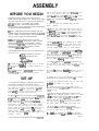
ASSEMBLY
BEFORE YOU BEGIN
WARNING: WHEN INSTALLING THIS GAME, A
THREE PRONG GROUNDED A.C. RECEPTACLE MUST
BE USED. FAILURE TO DO THIS COULD RESULT IN
SERIOUS INJURY TO YOURSELF OR OTHERS.
FAILURF TO USE A GROUNDED RECEPTACLE
COULD ALSO CAUSE IMPROPER GAME OPERATION,
OR DAMAGE THE ELECTRONICS.
DO NOT DEFEATTHE GROUND PRONG ON THE
POWER CORD FOR THE SAME REASONS AS GiVXN
ABOVE. USING AN IMPROPERLY GROUNDED
OUTLET COULD VOID YOUR WARRANTY.
THIS GAME USES A HIGH VOLTAGE COLOR
MONITOR. OESERVE
NECESSARY PRECAUTIONS
WHEN SERVICINGTHIS COMPONENT. SAFETY
PROCEDURES FORTHIS CAN BE FOUND IN THE
SERVICE SECTION OF THIS MANUAL UNDER
MONITOR SERVlCE & REPAIR.
TOOLS NEEDED: Before you start, you will want the
following items:
* 7/16’ Combination Wrench
* 7/16” Deep Well Socket
*Ratchet
-Side Cutters
-Adjustable
Pllers
If you plan on movlncr
our game often, or would
llke to speed up assem -g l y , a cordless Ratchet is a
gwd idea.
Yourgame requires a MiNIMUM CEILING HEIGHT
of 102” (B l/2 feet). Check clearance before
proceeding.
SET-UP
1. To begin assembling your game, remove it from
the shipping contalners. The game can be
removed by removing the 6 bolts and washers near
the bottom of the boxes. Your ratchet wlth 7/16”
deep well socket will work well for this. Lift the
boxes stral h t u p a n d o f f . R e m o v e a n y p r o t e c t i v e
packaging ?rom around the components.
The game i s bolted to the bottoms of the contalners,
and the bolts must be removed at this tfme. Using A
7/16” deep well sock,& and Ratchet, remove the
bolts holding the framework to the container
bottom. There are four bolts located on the flat
metal plates on the bottom of the frame. Remove
the bolts, and slide the frame off of the container
bottom. Open the access door (lar e door) on the
game cabinet You will s e e t w o b o 9t s w i t h l a r g e
washers located on the cabinet bottom. Remove
these bolts, and carefully slide the cabinet off of the
container
bottom.
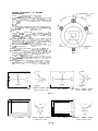
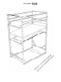
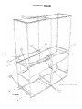
2. The framework of the game should be openad
and set up at this tlme. Refer to the drawings
at the
rear of this manual to see how the framework
should la3k when It Is set u correctly. It is a good
idea to install all hardwarePoosely, until all
hardware is Installed. This makes allgnlng of the bolt
holes easier.
3. Untie the ropes that hold the front and rear
frames
together.
4. Slide the two frames apart until the bolt holes at
the bobom
front of the rear frame, and the bottom
rear of the front frame !ine up. The front frame can
be identrfied b the hlnged panel attached to it.
Slide a 2-3 /2” 8olt with washer lthrough the two
frames at (A), and secure with a washer and nylock
nut.
5. Slide retainln
pins into locations (B) to prevent
the tubes from s ldin into the larger tubes when
the upper frame
y I s fu ?ly extended. If these are not
used the optical sensors may not work correctly.
6. With some help, raise the upper frame sections as
far as posslbte for your cefllng hel h t . Install I-3/4”
bolts with washers at locations (C3 . Secure with a
washer and nylock nut Be sure {that you count the
holes on the upper plpes on both sides to be sure
that the frame I s being Installed evenly.
7. install 2-l/2” bolts wlth wash,ers at location (D).
You must line up the holes of the two frames as well
as those of the upper frame. Secure wlth nykxk
nuts.
8. Install the ball return mountln brackets. They are
long square steel tubes with five ‘F, oles in each of
them.
9. Remove the 2 nuts at the bottom of the turntable
guide rails at the mlddle of the game. (E)
10. Install the mounting brackets onto the bolts and
m-attach the washers and nylock nuts.
! 1. Attach the front ends of the brackets to the
framework with 1/4-20x 2 l/2” bolts, washers, and
nytock nuts. (F)
12. Swing the hinged ball return panels up until
the meet the mounting brackets. Secure the panels
t o x e brackets to the panels wll:h the 2 112” bolts
and large fender washers suppllied.
Attach the
hardware from the inside out, so that any excess
bolt length will be facing away from the center of
the game. Secure with washers and nylock nuts.
13. At this time you will Install the Basket
Assembly. Push the Frame’s netting up and out of
the way to make room for the Assembly.
I 4. Instail the backboard post i l l t o the turntable
assembly. Be sure to feed the wiring harness for the
PAGE 5
ASSEfviBLY
basket sensor up through this post line u the hole
in the turntable assembly to the hole in t fl c
backboard tube. ALLICN
THE BACKBOARD and
secure with 2, l/4 - 20 x 2 l/2” bolts, 4 flat washers,
and 2 nylock nuts.
15. Install the backboard to the backboard post.
16. Adjust the height to maintain approximately 1 R
between the top of the backboard, and the top of
the frame. When using the lower hei ht settings,
this clearance wiill have to be lowe Jto
approximately 6” to malntain
clearance between
the hoo net. and the turntable. Try to maintain a
hei h t at allows the best an le for shooting the
bal YR
_ Secure the backboard wit1 one l/4 - 20 x 2
l/2” bolt, 2 flat washers, and a nylock nut
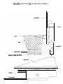
17. Connect the connectors from the backboard
tube harness to the sensor wiring connecters.
Push
any excess wiring into the backboard tube and
secure with a tie wrap as shown in the illustration.
IMPORTAM: LEAVE ENOUGH SLACK IN ThE
SENSOR WIRING TO ALLOW THE SENSOR RING TO
SWING FREELY ON THE NETTING. FAILURE TO DO
THIS COULD RESULT IN PREMATURE FAILLRE
OF
THE SENSORS DlJE TO WIRE DAMAGE.
18. You will now attach the cabinet to the
framework of the game.
19. Move the framework of the game into its final
position on locatlon.
20. Move the cabinet to the front of the frame, and
line up the four rnounU
holes in the franme t o t h e
mounting holes In the ca
T inet. Start four 114-20 X 1
3/4” bolts with washers into the cabinet (G) L e a v e
the bolts loose at this tlme as you will have to Install
the side covers of the game into this area later.
21. You will now connect the harness from the
turntable to the Main PC. Board.
22. Open the access door on the front left hand side
of the cabinet.
23. Feed the harness from the turntable through the
2’ hole located on tie back of the cabinet.
24. Connect the harness to the Main P.C. Bmrd. The
mating connector- is located at the lower rear o f t h e
PC. Board. It can only be installed one way.
25. You will now install the Ball sensor harness to
the connector in ,the cabrnet.
The ball sensclr harness
h a s down from the optical RECEIVER uni: located
onTie
:
upper front of the framework.
26. Feed this harness through the 1” opening on
the upper rear of the cabinet.
Through the arge
PAGE 6
access opening In the back of the cabinet, you wi!!
see a mating connector for the receiver harness,
Ccxnnec:
the two together.
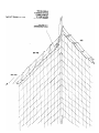
27. You w/Ii now attach the frame netting to the
framework of the game. A section of nylon rope is
used fcr this process This IS used rather than tie
wraps, as the rope can be fused over and over again,
which is important if you move your game often, it
also allows for easier adjustment, should it be
needed later.
28. Starting at the rear of the game, pull the netting
down secure1 , and lace the netting to the
framework. Tt( is is accomplished by winding the
rope around the frameworik
and catching every third
opening in the netting,(see diagram).
29. Start at the rear of the game, and work forwards.
When in the REAR of the game, put the rope
through the bottom mesh (opening.
30. When you start working on the rear SIDE, put
the rope through the second row of openings in the
mesh.
31. When you get half way forwards, where the
pipe gets higher, start lacir,g through the third ro’w
of openings In the mesh.
NOTE: lace about three feet at a time then go back
and pull the lacing tight one wrapping of the rope
at a time. It is important to pull the netting tight.
32. When you have all the netting fastened, tie the
rope at the front of the framework.
33. Using the su plied black tie wraps, fasten the
cable for the bal Psensor to the tube that runs down
the left hand side of the upper frame. Attach it so
that the cable runs down the back of the tube,
where it is not noticed when playing.
34. You will now install the fabric slde panels.
Unfold the side panels and install the supplied
plastic tubing Into the front seam of the side anels.
This will retain the panels tfo the front of the tame.
35. Push the panels between the cabinet and frame,
so that the tubing goes inside the framework. (See
illustration at the rear of the manual).
36. Tighten the cabinet
to the frame, so the panels
are pinched between the tilblnet and framework.
37. Using the black tie wraps, securely fasten the
rear edges of the panels to the framework
38. Using the black tie wraps, securely fasten the
upper edges of the panels to the frame NETTING.
39. Push the lower edges of the srde panels firmly
the framework to en age Me velcro strips that
retain the bottoms o9 the panels.
to
40. Install the reboun’d guard.This
is a clear plastic
panel with bent flanges. Attach the guard to the
upper front frame. (Thats the frame with the optical
receiver mounted to i’t.) Install where the Iowes:
vlslb!e adjusting holes are located. Install with tie
bent ffanges facing inward. Insert the 1 l/Z” b o l t s
and washers from the outside. Secure ith washers
and nylock nuts.
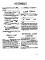
CUSTOMIZING YOUR
GALA E
This section will discuss areas such as settin
up
credits, time per game, awards, etc. The tab ?e below
will show how to enter into the game programming
mode and how to adjust many of the game’s
operating
parameters.
ENTERING SET-UP MODE
You must enter set-up mode to adjust all of the
ame features. This can be accomplished in the
23 llowlng
manner..
1. Open the game access door. This is the door
located on the left harld side of the game.
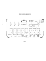
2. Locate the set-u button on the main P.C. Board.
It is located at the g ottom left hand portion of he
board. An illustration on the “programming” decal
on the inside of the access door can help you locate
the button.
3. Press the set-up button.
4. Programming modes can now be accessed by
pushing
the basketball buttons on the face panel
next to the monitor.
CHANGING GAME
SETTINGS
The numbers for each option can be changed
using the various buttons on the face panel.
b,+
1. Push the “option’ button until the arrow is by
the setting you wish to change.
2. Press the “up” or “down” button to change That
setting.
3. Press the ‘exit”
COIN
bu’tton
when finished.
MECHANISMS
The coin mechanisms have indlviduai
inputs for
each mech. Enter the “tame Options” mode to
adjust this setting. The coin 1 input controls how
man coins it takes to receive 1 credit. The number
f o r x e cnln 2 input is the TOTAL of the coin 1 input.
Exam le: If coin 1 was set for 2 coins
ad erng set on coin 2 would equa r
2 corns.
crdit.If
coin 1 was set for 4 coins per credit, a ” I’ being set
on coin 2 would equal 4 coins.
FREE PLAY
You can set your ame up for fme play by adjusting
the coins per cre2 it for coin 1 to “0”
CREDITS PEIR BILL
This option controls how many credits you
receive for each bill inserted.
CURRENT
wiil
CREDITS
This displays the credits currently in the game. You
can manually remove or add credits to the game by
changing the value of this number.
TIME PER CREDIT
This adjusts, in seconds, how lo,ng each game will
last. The game can be adjusted from 20 45
seconds. The recommended time for all games is 40
seconds.
GAME 1 POINTS PER
AWARD
This adjusts how many tickets or cards are iven
away for the “Quick Shot” game. The num % e r
displayed is how many points must be scored for
BACH ticket or card awarded. Setting this number
to “0” will turn off the dispenser.
GAME 2 POINTS PER
AWARD
This adjusts how many tickets or cards are given
away for the “Run -n - Shoot” game. The number
displayed is how many points must be scored for
EACH ticker or card awarded. Sealng
this number t0
“0” will turn off the dispenser.
PAGE 7
ASSEMBLY
GAME 3 POINTS PER
AWARD
This adjusts how many tickets or cards are given
awav for the “Hot Shot” game. The number
displayed is how many points must be scored for
EACH ticket or card awarded. Setting this number to
“0” w / I I turn off the dispenser.
jUST FOR PLAYING
gate. I
A setting oi “: 8
enables the alarm. A setting of “O*
turns the alarm mode off.
AI-TRACT
INTERVAL
This determines :he length of time between attract
modes. Chanae th,is number to chanoe the amount
of time in MINUTES between attract modes. Setting
this number to “0” turns this option off.
This feature is valuable in 2 respects......
1. This can be set to any value desired, so that if a
player, especially ,a youn
child can not get the
minimum points requr k?% t o e a r n a w a r d s t h r o u g h
the above settings, awards can still be dispensed.
2. This setting can give a predetermined amount of
tickets or cards per game, REGARDLESS of p,oints
scored, if the “points per award” and “winier”
settings are set to “0”.
WINNER AWARDS
This setting is used by itself if you want the WINNER
ONLY to get awands in a multiple player game. The
number of awards dispensed is determined by the
number selected. ,4 setting of “0” will turn off this
option. The winner awards are in addition to any
other awards being dispensed.
ALARM MODE
This feature is a great deterrent to tampering. The
alarm will sound under the following conditions:
1. If the ball gate I s forced open when a game is no:
in progress, or wedged open by bottles, cue sticks,
etc.
2. If the game is orer, or turned off, and 4 cr more
balls are thrown through the hoop, the game w / I I
consider this a tamper condition. This prevents
players from con:Lnulng
to play, even If they cut the
game mesh and remove the balls in an attempt to
play for free.
3. if the game is pcwered down during a game.
(Someone trying to keep the bail gate cpen.. The
bail gate will also automatically close al this time.
4. If the ball gate is open when the gan:e is
powered up. (Th!s indicates a problem ,*vith the bail
PAGE B
MESSAGE
CENTER
The MESSAGE CENTER is a feature that can help you
or your location by displaying important
information that you want your customers to read,
such as daily specials, special events, etc. It can be
programmed a s follows . . . . . .
1. Enter the “Scrolling Message’ optton.
2. Push the “Left” or *Right” button to to go
forwards or backwards through the letters,
numbers, and characters that are available.
3. Push the “Next” button tfo enter that character
into game memory, and advance to the next space.
4. Push the “Exit” button when done.
HINTS: You can not go back a sin le letter if vou
make a mistake. You must push t 5, e “ N e x t ’ b u t t o n
until you scroll around to the
message. A faster way to geit bat
Ynning
to the Ofbeginnlng
the
of the message, is to exit, and reenter the optlon.
You can clear the message In one of two ways. First.
either enter a new message over the old one, or
enter all biank spaces, to erase the old message.
Second, you can remove battery power to the Maln
B.C. Board and shut game power off. This will
remove the entire message at once. However, if you
do this, any accounting InfolVmation
or custom setups you have in game memory will be erased, and
must he reentered.
SELF TEST
A se’f test option is included with the
programm17g
to assist in
the factor,. This option ;s
diagnosing problems
ASSEM
1. Enter this option through the options menu
- by~ssingthesetupbuttonontheHaln
P.C. B o a
2.
Once
In the test mode! you can do the fdbwlng:
a) Push the face panel push buttons to check for
~iz3~;on$;dible
sound will
b)Thefacepanelpushbuttonsshouldllghtin
turn if they are working comatly.
c) h&we the cdn mech. mkm switch wim. An
audlbksoundwlllbeheafdlfthey0~
vmlidng ccImdy.
d) Pass your hand through the ball I n
sensor. An audible sot& will be hea53 I f
wcfking propsrly.
allow extra ~exlbillty
when dedding
on how YOU
want to MI your customers about game cost
E TESTING
ItiseasyandMvkabletob3stywrgameafter
lnstallath. After the game k sat up and all op&ns
have been set up correctly, perfwn the fdlowhg
tests:
1. Test for proper acceptance of money.
2. Test for proper dlspenslng
of cards or tkkets, i f
you have set that option.
3. Test for proper game play, including proper
-El-
e)Shootaballlntothebasket.lfthesensoris
working cmectly, an audible sound wfll b e
heard.
4.Testfc~pn~perr&ent&nofc~amememc1y,~
thegamepowefkshutoff,andtumxlbackon.
r) Notice that there are 2 sets cd numbers that
appear on the monltor.
If&e encoder sensors
“Es”9
xroHlupordownwhenthe
wllr-~‘afofmenb~
basketnuwes.
S.&uratocMyoureiectmnkg%ne counter,
andmibdownwryInfoyoumaywkhtorecord
from tipermanentcohmnonthekfth8nd
dde. ResrtheWear’buUononthefacepanel
toraetallnumberslntheresettablecofunnon
thelighttwldskle.
Toexitthesetftestmode,pressthe’set-up’buttOn
on the Main P.C. Eoard.
CREDIT COST
DISPLAY
The credit cost screen Is dkpla
attheendofthe
lNtructloll
screen. This Is used@
to display h o w m u c h
ELECTRONIC GAME
COUNTER
Your game Is ptwlded with an lnrwvsthr game
counbsr. B y Amply shlng the counter button
inside the coin mecrdoor, or enterlrg
the
accounting mode through the pmgramml
screen,
vou have access to accountha
Info+matJon %a tcan
played is also dkpbyed.
ented manually, as It dces NOT autonuOkally
changewttencdnspercredltareset.Thislsto
Toexitthegarnecounter,pressthe”Wt’button~
thefacepard.
PAGE 9
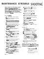
MAINTENANCE & TROUBLE SHOOTIN
QUICK TROUBLE SHOOTING
f===TZZPROBLtiM
PROBABLE CAUSE
NO SPOTLIGHT OR MONITOR
BAD FUSE A-r POWER MODULE
GAME UNPLUGGED
INSiPECT
MAIN FUSES
CHFCK POWER CORD
NO SPOTLIGHT
BAD LIGHT 3ULB
BAD MAIN CUSE
REPLACE BULB
INSPECT MAIN FUSES
NO MONITOR
BAD MAIN FUSE
BAD FUSE ON MAIN P.C.B...
BAD FUSE CN MONITOR P.C.B.
iNSPECT & REPLACE FUSES
AS NECESSARY
BALL GATE WILL NOT OPEN
OR CLOSE
BAD MICRC SWITCH
BROKEN WIRING TO SWITCHES
BAD GEAR MOTOR
CHECK SWITCHES AND
WIRES FOR CONTINUITY
CHECK GEAR MOTOR FOR
PROPER MOVEMENT
( perform self test 1
PUSH BCrrrONS
DO NOT
LlCKT OR WORK PROPERLY
BAD LIGHT 3ULBS
BAD MICRC SWITCHES
BAD WIRING
REPLACE LIGHT BULBS
CHECK SWITCHES AND
WIRING FOR CONTINUITY
BALLS DO NOT SCORE
CORRECTLY
BAD OR IMPROPERLY
ADJUSTED EbALL SENSOR
BAD WIRING
READ SERVICE
PROCEDURES FOR
REPLACEMENT OR REPAIR
OF SENSOR
CHILCKWIRINC
FOR
CO,NTINUllY ESPECIALLY
THROUGH ROTARY
MOTOR SHAFT
BASKET DOES NOT MOVE
BACK AND FORTH CORRECTLY
BASKETBALL. DUST ON RAILS
BAD GEAR MOTOR
BAD WIRING
OF TURNTABLE PLATFORM
BAD OR DIRTY OPTICAL DECAL
BAD OPTICAL SENSOR
CLEAN AND RE LUBRICATE
RAILS
CHECK OPTICAL SENSOR
CHIECK CONTINUITY
OF WIRING
TEST & REPLACE SENSOR
BASKET DOES NOT ROTATE
FROM SIDE TO SIDE CORRECTLY
BAD GEAR tAOTOR
CHECK GEAR MOTOR
(perform self test )
REPLACE CLCrrCH
TIGHTEN SCREWS USING
LOCK-TITE
CLEAN & RELUBE BEARING
TEST & REPLACE SENSOR
CLEAN OR REPLACE DECAL
GAME DOES NOT TAKE OR
ADD MONEY CORRECTLY
IMPROPER OPTION SETrINGS
BAD CLUFCH
LOOSE CLUTCH SET SCREWS
BAD WIRIN;
DIPITY OR BINDING BALL BEARINGS
iAD OPTICAL SENSOR
BAD OR DIRTY OPTICAL DECAL
BAD MICRO SWITCH
BAD WIRING
BAD DOLLAR BILL VALIDATOR
CHECK SERVICE MANUAL
FO’;I PROPER GAME SETTINGS
REPLACE MICRO SWITCH
CHECK WIRING FOR
CONTINUITY
REPAIR BILL VALIDATOR
PAGE 11
MAINTENANCE &TROUBLE EiHOOTlNG
PROBABLE CAUSE
SOLUTION
GAME DOES NOT DISPENSE
TICKETS OR CARDS CORRECTLY
GAME OmlONS SET IMPROPERLY
BAD WIRING
DIP SWlTfHES SET IMPROPERLY
ON DISPENSERS
BAD DISFENSER
RESET GAME OPTIONS
CHECK WIRING FOR
CONTINUITY
REFER TO DISPENSER SERVICE
MANUALS & SET DISPENSERS
TO EMULATE DELTRONICS
a:1275 DISPENSER
NO OR LOW CAME: SOUND
BAD SPEPKER
BAD WIRING
BAD MAIN P.C. BOARD
C:HECKSPEAKER WIOHMETER
C:HECK WIRING FOR
CONTINUITY
TEST & REPLACE MAIN P.C.B.
PICTURE ON MONITOR
DIM OR WASHED OUT
IMPROPE? ADJUSTMENTS
BAD MOt4ITOR
REFER TO MANUAL FOR
SPECIFIC ADJUSTMENT
PROCEDURES
REPLACE MONITOR
GAME DOES NOT DISPENSE
BALLS QUICKLY ENOUGH
NOT ENOUGH BALLS IN GAME
GAME REQUIRES 7 BALLS
PAGE 12
A%NT-EN/
OPERATIONAL
BACKGROUND
The following will outilne the bask operatin
prfnclpals
of the FULL COURT FRENZY” b a sif etball
game.
The positioning
ten1 of the FULL CCXJHI
FRENF b a s k ezr all game is operated by gear
motors that control both the linear and rotary actlon
o f t h e ame, and an optical
tracking
system to
contra ?the act& positlonirg
of the basket
assembly.
The linear (back and forth) motor, Is a 60 R.P.M.
m o t o r with hea
hlcorpomted
into
the gear box ltsef.“$~
Y
‘z& Ys a 6-24 volt D.C.
motor, operated at 12 volts D.C. This
ar motor is
attached to the side of the chassis rllcx nism, and
Ik ou ut gear mates with a rack gear attached to
o n e oPthe side ralfs. When the motor is activated,
this moves the basket mechanism back and forth.
The rotary (side to side)
8r motor Is also a 6-24
volt D.C. motor, opera terat 12 volts DC. Thlr
motor operates at 15 RPM., as this motor Is
connected straight up through
the chassis and into
the turntable assembly. Sinw t h e
r motor turns
slowly, md IS connected directfy,
rIs could c8us-e a
hlgh amount of stress from the constant changin
of
direction, as well as someone rotating the tumta % le
by hand.
To counter the stress levels imposed on the rotary
gear motor, we have lncorpomted
a heavy duty,
compact frlctlon
clutch assembly to counter ANY
stresses or shocks the lge8r motor might Incur. This
clutcth Is rated to last over 20 mlllion revolutions.
Becauw
of Its design, the dutch actu8lly gets
stronger after this Ume. As the average game played
will turn the clutch less than 1 revolution, It is easy
to see why the clutch will last a long time.
I of the turntable and chassis I s
optical
encoder P.C. Boards
located on and In the chassis. These optic81
encoders look at decals, one of whkh Is located
on
me of the guide rails, and the other, on the bottom
of the turntable. These decals have a series of bars,
or black and refTecUve sltver stripes on them. When
the gear motors move the basket mechsnlsm
baidr
and forth, the sensors see the bars go by them. As
the bars go by, they refiect light to the sensors,
ci-eatlng pulses that the microprocessor on the maln
P.C. Board counts. The game programmlng
counts
; ; ;$;artd converk these into numbers whkh
ition the chassis and turn the motors
on or off. xn the game Is Rrst powered up, there
Is no way for the sensors to know where the chassis
or tumtabie
Is positIoned.
For this reason there are
black areas at the llmlb of travel on both the linear
and rotmy decals. When the game Is first powered
up, the gear motors will run until the chassis and
turntable move ^ro a posltfon whera
the sensors see
the black areas. This lets the mIcroprocessor
get a
&t’=-&!&ifq’t$‘f’
Et; t;;;“$;z,t is.
The game Incorporates a through beam infm-red
optkal detection system for counting
balls that go
through the hoop. The system uses pulse
technology to rej& A N Y light that does not
conform to the requirements set forth by the
electronics contained wlthin the sensors. Thls
eliminates
annoying problems
that can sometimes
affect opUc8l sensing systams.
The g8m-a also uses a ‘Ball In Piay’ transmltt8r
and
recehrer located at the front of the frame to set-o*
balls as they are thrown into the game. This Is used
to help determIne
the parcentqes that are
disolared
on the stat!stks
Krterl8t the end Of the
ga&elThEs optk8l sensor also uses pulse technology
to ensure r&able operation.
The ball gate uses micro switchas
to determine
posldoning
of the gate, which are activated by the
cam on the ball gate shaft
A l l o f the gear motors use a comblnatlon
of
hardware and software control to protect
agslnst
mm current
damage. When an over current
condition
is detecti, the motors will shut off
yKhftiti
The game microprocessor will than
kr or not the motor should be turned
o n . I t will also determine at that Ume whkh way the
motor should run.
MECHANICAL REPAIR
IMPORTANT: USE ONLY I.C.E. REPLACEMENT PARTS
WHEN SERVICING YOUR GAME. USING NON-I.C.E.
APPROVED PARTS COULD VOID YOUR WARRANTY,
AND COULD CAUSE SERIOUS DAMAGE TO THE
GAME,OR INJURY TO OTHERS.
IF YOU HAVE ANY QUESTIOND
REGARDING REPAIR
AFTER READING THIS SECTION,. CALL OUR SERVICE
DEFARTMENT
BEFORE PROCEEDING AT
l-800-342-3433
WARNING: OBSERVE ALL SAFETY
PRECAUTIONS WHEN WORIKING
ON THE
COLOR MONITOR. DISCHARGE CURRENT
FROM THE MONITOR IN ACCORDANCE WITH
PROCEDURES WHICH CAN BE FOUND IN
THE MONITOR SERVICE MANUAL.
PAGE 13
MAINTENANCE &TROUBLE !SHOOTING
WHEN WORKING ON THE MOVING BASKET
DEVICE OR BALIL GATE MECHANISM, IT IS
EXTREMELY IMPORTANTTO
REMOVE
BATTERY POWER FROM THE GAME, AS WELL
AS A.C. POWER. THE BATTERY POWER CAN BE
REMOVED ElTH!ER
BY DISCONNECTING 1
LEAD FROM MIE BATTERY, OR REMOVING
THE 2 PIN MATE-N-LOCK CONNECTOR FROM
THE MAIN P.C. IBOARD.
e Use thread locking corn o u n d o n t h e
allen head set screws wI! e n
re-assembling the ball gate to the gear
motor.
. Assemble In reverse order of
disassembly. Tlghten allI hardware
securely.
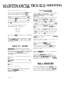
BALL GATE SERVIC:E.
* Fasten the side panels to the front of the
frame, using the Velcro strips provided.
- Be sure to test the ball ate unif
BEFORE Installing the !Bde panels.
- Re- both battery and A.C. power
* Bolt the cabinet
and frame together and
tighten securely.
- Cut all the tie wraps that hold the fabric
side panels to the game.
* Tk wrap the side panels
and cut off any excess.
- Removethe4boltsthathoIdtheframe
to the cabinet.
into posltlon,
* AE test for proper opetatlon.
- Move the cabinet away from the frame.
- Remove the IWO bolts that hold the front
of the bell gate bearing in place. (HINT:
a lo
extemiof7
on a ratchet can be
hel 3 I for this operauon.)
* Pull the ball gate from the end by the
bearing
towards you ( the rear of
the game ).
* The gear molar can now be pulled away
from the retaining
bracket
* Unplug the mate-n&ck connector frorr
the game harness, at-d r e m o v e the ball
gate assembtr.
- Remove the ;! allen head set screws, to
remove the ball gate from the gear
motor.
. Remove the 41 screws and star washers to
rermve the micro switch mounting
bracket from the gear motor.
- NOTE: When removing wires frcm t h e
mlcru switches or motor, It Is VERY
Important to Imake sure all wires are
returned to thelr proper terminals. Failure
to do this will result In improper
operation
of the ball
te, and could
damage the sgme. l-re wires are color coded,
so it will be essy to document
where each wire
g-.
- IMPORTANT: Mark the osition of t h e
1 racket so the
micro switch imounting
switch actuators will line up correctly
with the cam on the ball gate when the
unit Is re-assembled.
PAGE 14
.
+ Temporally shut off A.C. Power,
reconnect Battery, and turn A.C. Power
back on.
SERVICING FOR :
ROTARY h LINEAR GEAR MOTORS
F R I C T I O N CLCrrCH
ROTARY - LINEAR SENSORS (ENCODERS)
* Remove both battery and
AC. power.
* If the linear (back and forth) motor
requires service, the left side anel (as
viewed from the front) must L part.W
_
removed.
Cut the tiewraps off on the rear and t13
of the slde panel. The front edge shoul s
be left attached to the frame. It is not
necessary to separate Pihe cabinet
from
the frame.
- The turntable which supports the basket
must be removed to gain access to the
gear motors.
IMPORTAM: USE THE EXACT SAME SPACER
A R R A N G E M E N T W H E N REPtAClNG
THE ENCODER
SENSORS. FAILURE TO MAINTAIN PROPER SPACING
COULD RESULT IN THE INABILlTY
OFTHE
SENSORS
TO READ THE ENCODER DECALS.
a) Remove ‘the backboard Es
basket by removlng the
bolt that holds the post to
the turntable.
b) Disconnect the harness from
the optical sensor.
MAINTEN.
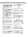
ELECBR.ONIC A N D
ELEC-BRICAL REPAIR
The following section will describe repair
pmcedures and troub’le shooting hints for the game
eiectronlcs.
Please read the section “OperatIonal Backgrourd”
in the beglnning of Maintenance and Trouble
Shooting to et a good understandlng of the games
basic operat ?ng parameters.
WARNING: EXERCISE CAUTION WHENEVER
WORKING WITH EILECTRONICS,
THEY CAN BE
VERY SUSCEPTIBLE TO DAMAGE FROM SEORT
CIRCUITING, OR PHYSICAL ABUSE. ALWAYS
UNPLUG THE GAME WHEN WORKING ON
HIGH VOLTAGE ARIAS OF THE CAML SUCH
AS THE TRANSFORIMER OR MONITOR.
USE EXTREME CAUTION WHEN USING VOLT
METERS TO DO CIIRCUIT
CHECKS IF THE
GAME POWER HAS BEEN LEFT ON.
ALWAYS REMOVE THE BATTERY BACK-UP
POWER WHEN WORKING ON THE GAME.
THIS IS NECESSARY, AS SOME CIRCUITS ARE
CONSTANTLY UNDER POWER FROM THE
BATTERY.
IF YOU MUST HAVE POWER ON WHEN
TESTING THE MONITOR, SHUT OFF POWER,
UNFASTEN THE MONITOR, AND SET IT UP
WHERE IT WILL BE TESTED, EITHER ON THE
CABINET OR A TEST BENCH, THEN TURN
POWER BACK ON. THIS WILL ELIMINATE THE
POSSIBILITY OF ACCIDENTAL DAMAGE OR A
SHOCK HAZARD WHEN REMOVING THE
MONITOR.
REFER TO THE MONITOR SERVICE MANUAL
FOR SPECIFIC INFORMATION ON MONITOR
SET-UP, ADJUSTMENT, OR REPAIR.
WHEN USING A VOLT METER, BE SURE IT IS
SET TO THE CORRECT VOLTAGE OR
RESISTANCE RANGE, BE@XE USING. THIS
CAN PREVENT POSSIBLE DAMAGE TO TH:
P.C. BOARD OR MISDIAGNOSIS.
ALWAYS REMOVE POWER TO THE GAME
WHEN PLUGGING OR UNPLUGGING P.C.
BOARDS.
IT IS NECESSARY TO USE I.C.E. REPtACEhiENT
PARTS TO CONTINUE WARRANTY COVERAGE.
USE OF NON-I.C.E.. APPROVED PARTS WILL
NOT ONLY VOID YOUR WARRANTY, BUT
COULD CAUSE SERIOUS HARM TO THE
GAME, OR CAUSE SERIOUS BODILY INJURY.
S:
IF YOU HAVE ANY QUESTlOINS REGARDING
REPAIR AFTER READING THl!S SECTION, CALL
OUR SERVICE DEPARTMENT AT
l-800-342-3433 BEFORE PROCEEDING.
FUSES
Fuses are the first thing that should be checked
when the game either appears not to work, or to
work incorrectly.
There are 4 ~JSE!S in the game. 2’ of them are !ocated
in the power entry module, where the power cord
enters the game.
To check or service the fuses in the power module,
first remove the power cord. Then, using a small flat
blade screwdriver, p the fuse block f r o m t h e
ower module. Pull txe fuse holder from the fuse
E lock, and test the fuses. Be sure to replace the fuses
with the same value.
There are 2 fuses Ixated on the main P.C. Board.
These protect the low voltage r,ides of the game,
the 5 volt and 12 volt sides. Be sure game power Is
off when checking or replaclng these fuses.
R e lace the Main P.C. Board fuses wlth the odglnal
va Pue.
TRANSFORMER
YOU MUST REMOVE ALL A.C. POWER FROM THE
GAME WHEN SERYICING
THIS COMPONENT. IT IS
A GOOD IDEA TO ACTUALLY REMOVE THE POWER
CORD FROM THE WALL OR FLOOR OLrTLET
WHEN
CHANGING THE TRANSFORMER.
CAREFULLY document where each color wire g-s,
BEFORE removing any wires.
Remove the 4 screws that hold the transformer to
the cabinet bottom.
Replace and reconnect the transformer.
TAKE ANY FAST-ONS
THAT WERE ON THE OLD
TRANSFORMER TO COVER THE UNUSED A.C.
TERMINALS OFF, AND TRANSFER THEM TO THE
NEW TRANSFORMER. THIS IS NECESSARY, AS THE
LEADS ON THE TRANSFORMER. HAVE POWER
ON
THEM.
CHANCING A.C.. VOLTAGES
When you receive your game from the factory, it
should already be set to the proper A.C. v&age.
If
for some reason however, it needs to be set to a
different A.C. voltage, follow these dIrections.
PAGE 17
MAINTErNANCE &
Unplug the game from the A.C. outlet.
The A.C. input taps for the transformer arc located
on the front left hand side of the transformer, as
viewed from the opening of the access dodr.
The AL. taps can be further Identified by Ihe fact
that there are 5 ta s in a row. (The only p ace on
the transformer wPI ere there are 5 taps in ,s row.)
The bottom tap is the 0 volt tap. One side of the
A.C. ilne should always be left attached to this
terminal.
The 5 taps FROM THE BOTTOM OF THE
TRANSFORMER UP are as follows:
240 V.A.C.
210 V.A.C.
115 V.A.C.
90 V.A.C.
0 V.A.C.
These numbers <are also indicated on the transformer
itself.
The A.C. wire that Is on one of the above t a p s , I s t h e
only wire you should move. Please use a blank
fast-on, on any open terminals, to protect agalnst
shock hazards.
MAIN P.C. BOARD
IMPORTAN-Tx
BEFORE REMOVING THE MAIN P.C.
BOARD OR CHANCING THE MEMORY BATTERY, GO
INTO THE CAME OPTIONS SCREENS, AND RECORD
ALL CUSTOM GAME SEI-TINGS, SO THEY CAN BE
RE-ENTERED AFTER SERVICING HAS BEEN
COMPLETED.
Remove all A.C. power before removing the Main
P.C. Board.
Disconnect
BWrd.
all Mate-lock connectors from the PC..
Remove the four retaining fasteners, and remove the
P.C. Board.
Install
in
the
reverse
order.
If installing a new memory battery or new P.C.
Board, after installatfon,
reset all custom game
prcgramming i n t o system memory.
PAGE 18
kE SHOOTING
B.I.P. SIENSORS
The B.I.P. (t,ail in play) se~~sors, are actually a pair of
2 diFfereat ?ypes of sensor. One is an lnfm red
tnnsmit:er, and !he other a receiver.
The transmitter has a power L.E.D. mounted on the
end of the P.C. Board, ooposlte the end that the
harrless I s attached to. Ii that L.E.D. Is I l t , there Is a
very good chance that thse circuit is working
p r o p e r l y . I f y o u n e e d t o lx sure, you can purchase
an I.R. detector card from Radio Shack Part No. 276.
099. Follow the Instructions on the back of the card.
You will only see the cyfktlon dimly, however it
will prove that the transmitter is working
properly.
The receiver has a test LE.D. located on one end of
the P.C. Board. Once you have determined that the
transmitter works properly, you can test the receiver.
If yc~u
wave your hand between the sensors, the
LED. should go out for a’s long as the beam is
broken.
If either of the sensors do not appear to be working
pmperly, do the following . . . . .
Remove the mate-lock connectors
sensor harnesses to the game.
that
connect
the
Unbolt the sensors from either the back of the
cabinet, or the top of the Ifmmework.
The sensors are both mounted In 1” x 2” black
tubular steel enclosures, and can be removed from
the enclosures by removing the five screws that
hold them in place.
Replace the defective
assemble the unit
sensor with a new part and re-
NOTE: WHEN INSTALLING;
THE RECEIVER P.C.
BOARD, MAKE SURE IT IS TIE-WRAPPED TO THE
PIPE SECURELY. TIE-WRAPTHE WIRING TO THE
REAR SIDE OF THE PIPE WHERE IT IS NOT VISIBLE.
OR PRONE TO BE HIT BY THE BALL
BALL SENSORS
The ball sensors are a through beam infra red pair.
To test, walk into the game, and pass a ball through
the hoop when a game of “HOT SHOT” is be@
played. (Choose HOT SHOT because the b a s k e t w i l l
only move once durlng the course of the game.)
When you pass the ball throu h the hoop, you
should hear the swish sol;nd f?o m the game. If you
hear the sound, :he sensors are good.
If you need to replace eiinei cf the sensors, refer to
the ‘llcnp Sensor Replacement” sectior~ i n t h e
mechanical repair area for dlrections
on how to
replace the sensors.
If you do not hear the sound, check the transmitter
sensor with an i.R. Delkctor
card (Radio Shack art
no. 276499). The transmitter Is the unit with t R$2 lit
1.e.d. In it. If you do not see an reflected I.R. lig?t,
do a v&age check to be sure x e sensors are
receivln
power. If the sensors are not recelvlng
power, ;r x the power problem and proceed.
R0TARY / LINEAR SENSORS
If you see reflected
I.R. light perform a continuity
check to make sure the signal from the I.R. receiver
I S getdng
back to the Imain P.C. Board.
If you have no reflecttd
light when It has been
estabilshed
that there is power, you have a defe:tive
TRANSMITTER.
If you have r-effected light, and have established that
the wlnng between the receiver
and Main P.C.
Board Is good, there Is a high probablllty
that the
receiver is bad.
There Is one Anal check you can make to be sure the
problem Is not In the IMaIn P.C. Board. Use a wire
r clip and jump between plns
jlul&Zelr4ZnFXZ
PS connector of the Main P.C.
Board. If you do this when a game is In progress, a
“swish” sound should1
be heard each time you
MOMENTARILY jump those terminals. If the sound
Is heard, and the wiring to the sensor is goad, aid
the transmitter
works correctly, then the receiver I s
deflnltely
bad.
The Rotary / Linear sensors can be checked easily.
Put the game Into the options mode (as described
earlier In this manual), and enter the ‘Bum In Self
Test” mode. You will notice 2 sets of numbers on
the monltor screen. These numbers should change
when the basket charges posltlon. Y o u w i l l no&e a
correlation between the number-s and which axis is
movlrtg (rotary or Ilnear).
If either set of numbers do
not move when the basket moves this will p r o v e
there is a problem with one of the sensors. Thls
should however be obvious as to whkh sensor Is
bad however. because that oartcular axls should
turntable by hand
motor).
MONITOR
Refer to the monitor service manual at the rear of
this manual for Information on service and repair.
PAGE 19
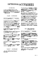
OPTIONAL ACCES
OVERVIEW
IF YOU DO NOT FIND ANSWERS TO YOUR
QUEfllONS IN THIS SIECFION,
REFER TO THE
ACCOMPANYING MANUAL FOR YOUR PARTICULAR
PRODUCT, FOR CALL OUR SERVICE DEPARTMEhT
AT 1-8OC-342-3433
CARD
DISPENSER
Refer to the supplled rnanual fcr all Information,
other than software settings.
The card dispenser software Is set u at the factory
to dispnse 1 card for each game p Payed. You can
however change this by entering the “GAME
OPTIONS’ screen and adjusting the award
parameters. If you set the winner optlon, only the
winner of MULTIPLE PLAYER games will get an
award, if the other award optIons are set to ‘0’
You can In addition set the threshold option whch
means a pla er would had to get XX points befcre a
card would L given.
The ticket dispenser comes pm-set from the factory
to dispense 1 ticket for every 5 Polnb scored. In
add&Ion to MS, If the game player dld not scme
h polnk to get 1 tkket, the game Is preset to
;Yvxe player 1 ticket ‘just for playing’.
These settings can be adjusted t changing the
U&t optlons in the “GAME OFx ONS’ mode. If
you cha
you rnay~~~o~~~3;~~~~~~~~~~~~~~
You can dis
nse a different amount of tickets for
each gamery adjusting the “GAME Xx POINTS PER
AWARD” setting.
For Instance, since It is easier to
score playing ‘HOT SHOT” than it Is playing
“QUICK SHOT”, you may wish la Ive out less
tkkek per pdnt on ‘HOT SHOT” 9, non ‘QUICK
SHOT”. Example 1 ticket per 5 points on ‘QUICK
SHOT*, and 1 ticket per 8 points on ‘HOT SHOT’
You can also set the game up so that the winner of
MULllPLE player games ONLY, ~wlns tickets, or that
a certain amount of
Ink must be scored BEFORE
ANY tickets will be 8”
Ispensed. This Is the threshdd
option.
To dispense 1 card per player per game, set the
‘JUST FOR PLAYING’ option to ‘1 ‘, and all other
award options to ‘0”.
The “CAME _ POINTS PER AWARD’ optlon should
be kept at “0’ at all times, unless you want to
dispense a card for every Xx points scored.
Your card dispenser should be cleaned every time
ou put more cards In It. This is because the cards
rwve debris on the rollers, which will make them
slippery,
and not dispense properly.
BILL VALIDATOR
Refer to the silpplled manual for all Information
other than software settings.
The valldator
normally requires no adjustmenk
othef than chccklng to see that the pinper vdtage Is
present This valtiator runs on 12 volt D.C.
with a mlnlmum of 11.5 vdk DC. The vail F
ator will
not work correctly with vdtages
below that
SpeclBed.
Elcw out as much of the pa r dust as possible. Use
a rubber rejuvenator on a c r
can cloth, and wipe all
the rubber roller contact surfaces.
The validator may work strangely, or not at all if it is
grounded Improperfy.
If the cards have a bend to them, the bend should
bshe rollers, so there Is maxImum contact belng
The unit should be cleaned periodlcalty
to ensure
proper operation.
Blow out as much dirt as possible,
then use a cotton swab (q-tip) in get into the front
open4 to remcve any rcmahhg dhi cw de&k.
If the unit does not wlork at all, be sure the ame
software options are set correctly, and that 9,
dispenser Is recelvlng
12 volts DC.
Clean the stMker belts with a rubber rejuvenator.
Clean any other dirt from the unit with Isopropyl
TICKET’
DISPENSER
alCdld.
The game comes from the factory pm-set at 2 credltr
per bill. You can change this by entering the
‘GAME OPTIONS” screen. ( see GAME OPTIONS
settings sectlon for more Information.)
Refer to the supplied service manual for all
intormation, other than software settings.
PAGE 21
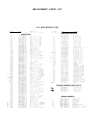
TS LI
MECHANiCAL PAKTS
LISTINGS
BBlooO
881001
BB1002
881003
881004
881005
BE1007
BE1008
BE101 3
881016
BE101 7
BE1018
BBlO20
681022
BE1023
BE1024
BE1025
EB1034
881036
881037
861039
851041
883001
BE30023
BE3003
BB3004
BE30056
BE3006
883007
EB3008
BE3009
683012
BB3012A
883013
BB3014
BE301 7
BE301 a
EB3019
BE3020
BE4001
BE5001
5014
DRIVE Rp,IL WITH RACK GEAR
CHASS’S SLIDE RAIL
TURNTABLE (WITH POLE)
BACKBOARD MOUNTING BRACKETURNTABLE
CHASSIS
COIN DOOR PANEL FRAME
ACCESSORY
DOOR
CASH BOX D O O R
CABINET TOP PANEL
MONITOR MOUNTING BRACKET
MONITOR ADAPTER BRACKET
SENSOR HOUSING
BALL RETURN MOUNTING EKT.
BALL GATE
BALL GATE MOTOR MTC. BKT.
M I C R O S W I T C H MOUNT-INC BKT.
EXTENSION POLE
CLUTCH (XIC-1803)
TURNTABLE STOP BRACKET
RACK GEAR GUARD
HOOP (2043-O) 3/8 X 1 3 ”
CABLE SIJPPORT CHANNEL
7” BASKETBALL
BACKBOARD
TURNTABLE COVER
NET SENSOR RING
MONITOR FACE PLATE
RAIL BEARING
iL41L BEARING PLATES
HOOPNET13’
FRAME NElTINC
VINYL SIDE COVER, LEFT
VINYL SIDE COMR, RIGHT
REBOUhlD GUARD
CABINET SIDE PANEL
BALL GATE BfIARiNGMTC. PLATE
BALL GATE BEARiNG
MOTOR NOISE COVER
MAGNETIC VRIP
VELCRO (HOOK)
SYSTEM4 CASH BOX
DOOR LOCKS
HARDWARE
HH3031
30368
3039
348
351
1 ’ G R O M M E T (GRO-l-VL)
FACE PANEL WASHER .875X 5/16
2” tRO,MMET (BP21
TIE WRAP, 5” tiH~~t:
TIE WwrP, 21” WHITE
s
352
SK403
BE6001
PC6060;
BE9004
l-l E WRAP, 8 * BLAC:K
BUMPER STOP
BALLTRANSFERS (I’&2200)
FACE PANEL BOLT l/4-20 X 5/B
BOELUBE WSH STICK RAIL LUBRICANT
DECALS
887001
BE7002
BE7004
887005
EB7004
BB7007
BE7010
BB9CQl
PROGRAMMING DECAL
MONITOR BEZEL
POWER DISCONNECT WARNING
F.C.FRENZY CAEINET SIDE DECAL
LINEAR TRACK ENCODER DECAL
ROTARY ENCQDER
DECAL
MONITOR WARNING LABEL
OPERATORS SERVICE MANUAL
E.e .ECTRICAL
BE2002
BE2ob(
EB2005
BE2006
BE2007
BE2008
BE2009
BE2010
EB2016
BB2018X
862019X
EE202OX
BB2021X
BE2022
882023
BB2025X
BE2026X
882027X
BB2028X
EE2029X
PARTS
TRANSFORMER
BASKETBALL PUSH ELllTON
MICRO SWITCH (CHERRY D-44)
POWER ENTRY MODULE
SPEAKER
BALL GATE MOTOR
ROTARY GEAR MQTOR
LINEAR GEAR MOTOR
BAlTERY, 12 VOLT (FS1242)
CHASSIS HARNESS
MAIN CABINET HARNESS
MOTOR SHAFT HARNESS
BACKBOARD
HARNESS
FLOOD LAMP SOCKET
FLOOD LAMP BULB 15OWAlT
TRANSFORMER
HARNESS
PANEL SELECT HARNESS
BALL IN PLAY RECEIVER HARNESS
BALL IN PLAY TRANSMllTER
HARN.
GATE ASSEMBLY HARNESS
ELECTRONIC PARTS
BE2001
EB2003
BE201 1x
BE201 1 x
BE2012
BB2013
BB2014
MAIN P.C. BOARD
19” COLOR MONITOR
NET SENSOR RECEIVER
NET SENSOR, TRANSMllTER
BALL IN PLAY TR4NSMlnER P.C.B.
BALL IN PLAY REC:EIVER P.C.B.
POSITION ENCODER P.C.B.
PAGE 23
,5u
m
u7
REV 1
I .C .E . Inc.
r?LRMSND
=.
u12
i--------i
REV 1
I-
I.C.E.
I n c .
H
SJ
-, U 9 9 3 8
t
R’I
,? 1OK
I
I UR7
G
I
1’
F
E
CSYNC
HSYNC
- - ID
I
R5
C
-“on DLL”
1
CBDRP
Rb
Y
10K
-
v*”
33
-
CUID
R7
330
-P
:
B
I
r-l
REV
1
!
I.C.E.
Inc.
H
t,
L-.1 ..-._ ---l---.---m -c- -_-----. I.--
5 -c--‘IL-- 3 - -I 2 I H
zone
1t.r
le”1510”5
descrlptmn
1
1d a t e lapproved
--FR
I
G
t-
E
R03
Y-EN!3
R-EN0
- - -
RN5
RN5
+
u
C
‘B
1
n
TSEN
__D-EN!4
“7
,
RYl c
Ltl3'tOAT-9
URl
D2Lt
lN’tOO1
1
18U
+
/LED2
Tl-3/V
-r?t7
68OOuF
7
.I
f
Ill?
j=++
lN'il'l8
D15
CLOSE
R38
12K
, MC1723 ,
I
C
B
I
r
12BU
*18U
I
1 cc50
TLt70pF
RLtLI
15K
I
- 12BU
zR$iE
f
^.,.^
1NLtlllR
c52
-:I
T 1ur
10K
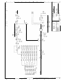
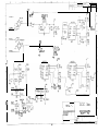
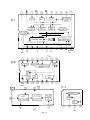
BnSKETBnLL
GWlC
NAIN LOGIC PC9
Iltuaca
---A-<
7 5uac.3
----&c
7 5UFICb
p--s,
x!WLL--lt-<
H
I II
CONSOLL
POWEK
P1
LL)UAC
7 wnc
7 5unc
lq”AC
REMOTE
P2
!E-L+ Rx
G
BUTTON H2
-+ GNII
GND
TX0
Lt
Tx
tr
L
F
7
P3
COMPOSITE
UIDEO OUTPUT
cum
77
E
RUDIO
OUTPUT
+
II
-
C
B
,12U
*
BALL GATE CLOSED
P’I
TICKET
PI0
:
TSEN
TROT
TCNT
BALL SWSE
BRLL GATE OPEN
t
BOSKET
II
BFITTIIRY
COIN DOOR
C
COIN COUNTER-
)
REU
1
1
l.C.E.
Inc,..-.v.
B
[
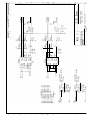
BWKETBRLL
GWlE
WIN 1 OGIC PTA
r-l
I
a
1
RN 16
4s
10K
RN20
IOK
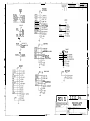
BASKETBRLL GWlt
MAIN I OGIC P C B
4
G
5u
SJ
4
G
F
F
:
F:
E
t
t
n
Ll
B
BFlSKETBFlLL
CAME
i
THE PRISMATIC BY
WELLS-GARDNER
COLOR SPECIFICATIONS
CRT
VIDEO CHARACTERIS’JICS
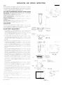
. From 9” to 25” diagonal measure
. P22 phosphor
. Polished faceplate standard: variety of opttonal
faceplates and transmittances available.
l
Stripe trio spacings (standard): 0.62 mm (9”)
0.66 mm (13”). 0.82 mm (19”), 0.82 n;:n ;2,“).
l Option21 firier pitches available.
l
INPUT
l
l
MECHANICAL
l
The 19” mor1lor is also avallab!e
in universal mount
brackets. The monltol~ can be mounted in the user’s
cabIre: hor;zontaliy 0’ vertlcairy.
Coniacr ‘joijr sc!i%
representative for details.
l
The standard Prismatic- 2 5 ” 25” monitor 1s avaIlable
as a ki: wlthour a frame. Custom frames can b?
i-rn:si!ed.
l
The standard
a kit without
adaptable to
Conract your
SIGNALS
. Video: RGE ynalog, Iv to 5v peak-to-pea, ,,qc;dst~~!e
with contrast control), 4.7k ohm inpur I-iir-edince,
40 usec to 50 uscc active video.
Optional inputs available:
l Negative
video
. RGB analog 0-0.75~. 75 ohm input ~rr~,padan;:
Composite iiideo INTSC)
. Both composite video and RGB analog 5orr !;gnal
sources can be connected to the momtcr a: t’: same
time Monitor dispiay can be switchec fron one to
the otner, at anytime at pixel or ve-t!cai
fra’nt rate.
Bandwidth (-3 db): 12 MHz typical
Rise Time: Less than 50 nanoseconds
Overshoot (max): 5%
l
Prismatic-9” 9” monitor is avai.able as
a frame::
Also available in chassis form
individual customer requirements.
sales representative for details.
l
l
Sync: TTL positive or negative
going, s?oa-dte
or composite
Input Impedance: 20K ohms fzr 2cs.i ve going
sync; 12r< ohms for negative going sync.
USER
PO1VER
l
HORIZONTAL
l
l
SCAN
from 40 usec to 50 usec.
Frequency: 15.1 kHz to 16.8 kHz
scan frequenzles avaliable.
SIZE
REGULATION
. 2’4;
VERTICAL
l
l
ADJUSTMENTS
INPUT
monitor
Frequency: 47 Hz to 63 Hz
Linearity: + 5%
CONDITIONS
OperarIng temperature O” to 55’C. Comphes with
U.L., C S A., and D.H.H.S. radiation performance
standard (composite video).
RESOLUTIONS
l
SCAN
GEOMETRIC
l
AND
120 VAC +iO% -15’a. 50~60 Hz, 85LV (maxj
lsola?1on
transformer required; furnished bv*iltlh
as an optIon.
ENVIRONMENTAL
standard. higher
Linearity: 2 5%
PICTURE
l
CONTROLS
Width: Ad,ustable with just one co11 [c a;conmodax
active video
l
ADJUSTABLE
. Brightness, Contrast, Horizontal Hold, Horlzonral Size,
Horizontal Raster Posttion. Horizontal Video Positton,
Vertical Ho!d. Vertical Size, Vertical Raster Poslttor,
Focus Custom Control Location available.
Standard CRT
9” 280 Pixels
13” 400 Pixels
19” 400 Pixels
25” 560 Pixels
l
x
x
x
x
240
240
240
240
Lines
Lines
Lines
Lines
Fine Pitch CRT
410 Pixels x 240 Lines
640 Pixels x 240 Lines
640 Pixels x 240 Lanes
N. A.
DISTORTION
t 2% imax).
CopyrightG
1987.
Wells Gardner Electronics
All rlglts reserved.
-*--
Corporation.
SPEClFlCATlONS ARE SUBJECT TO CHANGE IN
ORDER TO ASSURE: YOU THE LATEST IN DISPLAY
TECHNOLOGY.“”
W A R N IN G : FOR CONTINGED SAFE” PLC,AC.E SAFEN CRITI,ZCL COMPONENTS ONLY LS/ITY NANUKACTL!QE8
MENDED FARTS THESE PARTS ARE ‘DENTIFIED BY SHP3’6”
,,I” bND BY (.1.! ‘IN THE SCHEMA-IC DInGRAb?
RECOb+
AVERTISSEMENT: POUR MAINTENIR LE DEG=E DE SECURITE UE LAPPAREIL
NE REMPLC,CEQ LES COMPOSAYiS
DChLE FONCTIONNEMENT EST CRITIQUE P3i’R LA SECURITE OUE PAR DES FIECES REC3NMANDEES
PAR LE FABRIC4NT
For replacement purposes. use the save :,‘x or specified type of w:re and ,saole. assuring :‘7e pos~t~or~ng of the vvres IS
foi!owed (espec,ally fo: H V and pc~we’ sup?‘:: c rcu,tsJ ilse nf ?:tewattve iyir~n$ or pos:~t~omng could r e s u l t I” damage tci
the monitor ,?r ,n a shock or fire hazard
AC CONNECTORS AND TERMINALS
ALL MONITORS EXCEPT THOSE WITH MODEL NUMBERS ENDING WITH 2 OR 6:
WELLS-GARDNER
END
Fillg
Pin5 M a l e
W.G Pati No
Mo’ex Dart
GAO396-501
30x0759-003
19-09-2029
02.09,-2101
ND
USERS’ END
Receptacie
Fins. Female
or
19-09-1029
02-09~1101*
02-09~: I! 6‘
MODEL NUMBERS ENDING W TH 2:
WELLS-GARDNER
END
WG
Plug
Pins, M a l e
Part No
Molex Pari Yo
6AO376m002
30x0759-00!
03-09-2022
02~09~21Gl
USERS’ END
Receptacle
Pins, F e m a l e
or
03-09-1022
02-09-1131’
02-09-l 116’
MODELS NUMBERS ENDING WITH 6:
WELLS-GARDNER
END
WCI
P,rtNo
AMP P a r t N3
6An40?~001
20X075’-001
Pwzeptac’e
Pns. Male
350778-l
350538-l
USERS’ END
PiUg
P’llS, Fe-nsle
or
‘~1101 IS used icr 2C-i4 01*$G
‘v+ re and insul::!~r~n
350777-l
350537-l +*
350851-l ‘+
diameterrange 0065 -0 160’
11 ! 6 IC: tised for 22~ 16 A:‘JG ‘wv: and in~ul~ tiop d:ameterrange 3 C60’ -0 120
*+ 350537-l IS used fs3r 20~14 AV/C w’re and instildtlnn
3~0R~~:
1 i s Used i83r 24-18 A’:JC wire and 1rl~,ul,3t13n
diameter ra?ge 0 130,-O 200
clI3me:or
i3’lge
0 r84O’~f) 1 0 0
U S E R
A D J U S T M E N T S
FIG. 18
INSTALLATION AND SERVICE INSTRUCTIONS
FIG. 2A
FIG. 4
/-ANODE
CCNTACT
,,-RUBBER
WEDGE
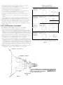
’ 6 P O L E C O N V E R G E N C E MAGNETS’ CONVERGENCE
--4 POLE CONVERGENCE MAGNETS \
-PURITY
CENTERlhG MAGNETS
i MAGNET *“”
‘-DEFLECTION
YOKE
/
FIG. 6
PRECISE ADJUSTMENT
CONVERGENCE
1
OF
DYNAMIC
Feed a cross ha:ch signal to the monttor
2
Insert wedge tempora:lly and !!x the Def’ectlon
Yoke 53
as to obtar the best c!rcumference
corv~rgence iSee
Fig. 8 ana 91
NOTEThe wedges may need to be moved dunrg ,adjustments
3 !nserl three rubber wedges to !he pos+3n as shown In
NOTE
1) T!Iting ~+e ang!e of the yoke up aqi: dc,wr ad,As We
C~OSSC~D~
of both ver%cal and hori?on:a; red and Dlue
ilnes See Fig 8 ~:a) and tbi
‘21 T,ltlng the angle of the yoke scie~a~~ ad:us?s the parallsl
C~nveqence cf both hortzontal and ve17
oil lines at tke
edges of the screen See Fig 9 (a) am lb)
3) Use three rubber wedges (tapered r~,bi:c: wedges a’e
ilsed for a purpose).
4) The position of each rubber wedge IC s”ou n ,n F!g T .
51 Do NOT force the permanent wdges IQ TWy are to hs
inserted wtl! they ju.st make oortact with ihe yoke-after
the yoke has Dew posltlored
61 Ftx the :hree oermanent rubberwedges +.:th chioroprere
ruobe: adhesive
T) After ?he. adhesive has dried enoug’i :g “sic the wedges
KI piace carefu’ly
remove tne ternocv:~r~lv ‘1s alied wedge
FIG. 7
R
G
B
R GE
CRT
SCREEN
(0)
INSERT PUEBER WEDGE
FROM UPPER SIDE
CRT
SCREEN
(bl
INSERT RUBBER
FROM LOWER
WEDGE
SIDE
FIG. 8
CRT
SCREEN
(01
NSERT RUBBER WEDGE
F R O M LE F T S I D E
FIG. 9
CRT
SCREEN
lb)
INSERT RUBBER WEDGE
FROM RIGHT SIDE
WHITE
BALANCE
: EquipmentRoqwred An oscilloscope wsth a DC coupl?d
modt: in the verticalampllfler
2 ReferrIng to Fig 1 and 3, do the fc~llo’wiiS ad~tistments
in subdued light after degausslng and settIn the pur!ty
of rhe CKT
3 Grou-~d the R/G/8 video inputs Apply syrx slgna!s 13 tne
sync inputs
-: Set ali three dme com’ois. VRZGZ, VR2OJ & VR2’&, ?o
thw mIdpoIntso f rotatlorl
5 Set the screen end R/G/B cutoff COnidS to the!- m!nrm u m (fJy CCWI posItIons.
6 Connect the osc!iIoscope
to the collect~3r cfzv,deo o.I:ijuttrans~storQ201.Q202,orQ203o~totheendofR2l~7
R208, or R209 lrdicated on Figure 3 as Reel. Green or
Bl&
7 If tills white balance procecrure is required because the
CRT or neck board was replaced, then leave the cont r a s t contra! at its onginal setting i f t h e c o n t r a s t cofitrol IS known to be 9rossIy out of adlustment.then :,et
11 is 11s center of rotation Adjust the brightness ConirOi
V R 6 :o obtain t h e wsveform s h o w n I” Figwe 10 N,w
remove :he scopu probe
IO Adj-si t h e !v:gn:r~esj cOi,i 9, I,i a di;il rdbiei kdjU>i ihz
t,v”o remamning LJ?oit con:~ls s,NOT tr,e lead COG- gtir:
c~tcff con!rol! ior best grs) uniformity.
11 Ad,ust the br g-iness con:rol ror a bright raster but not
mzxlmilmbrlghtnass Adjust tne RIG drove c o n t r o l s , IT
necessary for best neutral Kilite Try no: to adjtisr :he
blue drwe contw
12 Repeat steps 13 and l<uni~I Good tracking of whiie bdlanie 1s achle’ged End with step 10
13. With the oscisloicope
com;ectedto the collecloror me
lead coior wdeo output tra8wsto:(See Fig. 3). adlust the
brightness ccwro! to obta n !he waveform in Fig 10
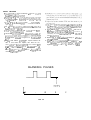
BLANKING PULSES
i 0
-
W
FIG. IO
D
C
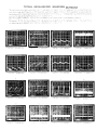
TYPICAL OSCILLOSCOPE WAVEFORM PATTERNS
TROUBLESHOOTING
NOTES
1 Thr tiaubleshoctlng chart mertlorv.
SpeClflC
ColrlpOr~erlts
t0 LIV Lllechti: I II is Inlendeo tt,dl
enttre circuit ass,octated
with these Components be checked
the
2 Th!s c’;ari ,s a guide to servung rather than h complete l!st of each component that could fali
Therefore. troubleshooting should not be I,inlterl or~ly to those compone-Iis mentioned !n the chart.
3
1
it s aihays
useful to begin c’lecklng a circut by measuring the DC voltages and tnen comparing
the medsurerne,-ds
to those llsted in Ihe T!.p~cal DC Voltages cha?
4 1 he cutoff con?ro!s and dnvc controls con the rwck board arld the screer controi at the bottsm
of
the flyback
transformer have been preset at the factory When sewii~ng the monitor for a lack of
woeo. do not adjust any of these ctxtrol!; ur7less It IS suspected that the problem IS a result of
these controls bavlng been tampered WI!+ Otherwise do not aa!ust these contra s. if they are so
severely out of adjustmen! tb,at there IS a lack 01 v)deo, then there 16 something malfunction
ng
5 The W~llstiardner SewIce Department aces accep: telephone calls for sewclng assistance. Ca,i
1~312-252-8220.
between 7 OOam and 3 3Opm Central Time ASK for the Service
DepartmeN The
ServiceDepartment IS closed dilrrng theft/St two weeksof-u!y Tel~phoneassistancels notavailable
duricg this period. Before call,ng. be sure to have avaIlable
the model number of the morvtor being
serwced and the schema!lc diagram of the monitor being serviced
6 Replacement parts may be ordered from ?he Service Department befween 7 OGam and J3Opm
Cerltral Time
7 All moutors are equipped wth automatlc Uegaussing
colis Khlch
dcrnagnetlze the picture tube
everyt!methernonltoris turnedonafterbe~ngolfforam~n~mumoi20m~ri~tes
Shouidanypartofthe
chas% become magrwtired It wll be necessary to degauss
the affec:ed
area with a manual degauwqg co:1
Move the co11 s!owlyarounc the CRT tace area and al! sur’ounding metal parts Ther.
sfowly withdraw for a illstance of 6 feer before turning o f f
0. Horizontal vs. Vertical:
Scme models have the picture tube mounied vertically
rather tnan honrontaliy Ti?at IS, the p:cture
tuoe 1s mounteu in the frame such that the lo;lg dimension of the tube IS up and down. Examples
of this Include (but are act limited to\ fvodeis
13K7851
and 19K7951.
Other than the physicai
or,entatlon of the picture tilbe. there !s no electrical difference between these models and therr
hcrlzontal counterparts. The same c~rcu~is. the vertical clrcults.
produce and controi deflection
along tne short dimension of the tube in ail models
Tba same circuits. the honror;tcll cwcwts, pro&x and control deflection alony tht? long dimension
of tne tube in aIi models Therefore, v&ert?ver
“veitlcal“ appears in th!s manual or on the monitor,
;t reters to the short dlmenslon of the picture tube. wherever “norlzontal” appears, It refers to the
iony dmenslor, of the picture tube.
I
i
TROUBLES ;HOOTiNG CHART
The focus vo tage and the screen, GZ, volrage are obtaIned
from the aqo3e voltage with a resistor dwder network with
! n t’?e Tl a s s e m b l y A n auxiltary wIndIng (p n -0) provides
feedback t3 the howonta’ A F C throw;? R71 R70 and C29
T h ! s signa! 8s also used to filrn:sh the hor’zsnta blanK!lg
tnpvtto IC! v a C28. R69. and R68 The s~gpal fror- the auxm
111ari wInding at pin 5 of Tl IS rectified by D14 and fIltered
to providethe +12VDC suppiy for the video ~~~!e?ace a?d
p)ni: CI-CU~~S
The a u x i l i a r y w,n31ng c f pins 3 anti 4 tir3dLcc~
a s,c~al w’l~ch rs rect,‘!ed by Cl3 and fl’fcred to z,:dtice the
+24VDC stipdy for ?he vertlca! output CI:WI:
HI G H
V O LT AG E
HOLD-DOWN
ClRCUiT
T h e h i g h vcl!3ge hold dew ctrcult ,s part 5f :nf? ma!” PC
board P447 o+ thts monitor, The +lZV DC supply is sensed
v!a D:CI S we the -I-12V D C supply IS flybark n2lr.e dewed.
the +12V 0; supply wil! rise 3s the hlcb vY!age r i s e s I f
the Al&’ DC exceeds a threshold wwch 1s ‘,et w!th VR8
then 212 w~ii conduct. there!!y provldly drive to!CZ. pin 5-hoiddown llput of deflectlnncsclliat3r IC The iwe bel?g
appl ed to p’” 5 causes ?he horizontalosc lla+cor ivlthin !?e
! C to shut ?owr-thus preventing the gwewt~!!~
of hsgh
VZl!Zg;!
The ‘iorizontaiosc\ilat@r ih.11: remain IKI i ? s OF’ state. even
if the inptitto IC2. pin 5 I S removed. unlws anl until AC
Low?r IS removed froT the monitcr ir!p’Jt The Rowe: may
then be reaoplied
V E R T I C A L OSCiLlATOR P.ND O U T P U T
The compos~fe sync ouput oflC2 p’n 12 is f teri-d through
the petwork of R65, C25. C24 and RI?6 so ihit c:l’y vertical
sync 1s app’,ed to the veti~cal lr,gger ,nor~t ri: pin 14 Yheveti-tlcalosc~! atorfreauency~sco-tr?~lPdhytheveri,c;!hoidcontrol a n d its qput t o o’n 10
r
-- ,-8j7l~6,-\5*4m,2*1^R1 P’ IB
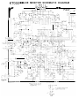
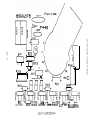
Ki’OOO C O L O R M O N I T O R S C H E M A T I C D I A G R A M
“Z
is,
;,u. ”:%;ic,
t
7
i
c
!!.7-Ti
SK7700
13K7800
19K7600
19K7900
SERIES
SERIES
SERIES
SERIES
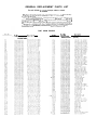
GENERAL REPLACEMENT PARTS LIST
For all K7000 rr.odels except where noted.
I his monitor contains CIKUILI i1nd components
nc~~iled specifically
for safety purpxes
For cont,nued
protectlon 10 changes should oe n~;ide to the orqinal
design. ana components shxur, in shaded areas of schematic, or’+
01.1 parts lrst should be replaced w v l t h exact factory replacement parts.
Theuseofsub~titutepart:;maycrealeashocic.flre,
rddlat,onorother
hdrard Serwce should be performed by quailfled orrsonnei only
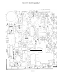
P447 MAIN BOARD
Part NO
UebCrlpfson
RESISTORS
Ret NO
Part NO
~-
.~~
RESISTORS
Dricr,pllon
(Cont.)
REPLACEMENT PARTS LIST
SEMICONDUCTORS
CAPACITORS
t
* I
‘.*-‘
__
MISCELLANEOUS
REPLACEMENT PARTS LIST
P448 NECK BOARD (Used with CRT’s with a 29mm neck diameter)
Same as PC56 NECK BOARD except:
Cii?ri JLI
;cz ;n;
,i-:.‘i!‘
FINAL. ASSEMBLY PARTS
R‘z!
hii
Pa:, hc
__~
DeS‘rlDtlO~
9K7700 SERIES (9”)
“I l
*
*DDNC!T
MEASURE
-CiGDE “40
ANODE
a.5
-
0:
3kTH3DE
31
D?
a.5
91
D3
8.5
11.0
r
r
3
c NO
L
4
33
43
0
163.5
2.0
6.8
12.2
125.2
D4
a.5
1: 0
2
35
0.9
11; 7
3
2.7
67
23.6
36
03
IO.7
4
2.0
06
0.8
37
0.9
:37
5
27
05
0
D8
0 55
05
7.1
26
E
2.0
03
24 0
12.0
7
27
09
22
21
3.5
DlO
120
114
8
D: T
0
26
9
:3
0.3
9.8
10
I04
62
7.9
0.6
D1?
0.05
D13
_...
24.0
11
DlL
0 17
-22
:2
80
13
i23
Dl5
3
Cl6
Dl7
123
DIE
e
D’E:
D?O
0
021
c
D22
14
2!
13.7
15
IO 5
f
16
iL'lJ
64.3
17
_I
la
19
20
16L 3
21
2
02;
' DO "~07 i:'EASUHE
2; 0
1.3
120
325
G25
0
0 55
23 t
2
08
i 2.6
0
1230
,R
I
II
r,
R
1 CONTRAST AMP +--/El
L K 1
- - - / ]SEPARATIO
BLANKING
vcc
VCC
VCC
IC4
IC3
+7
FIG. 11
--r--*\
CUTOFF WED DRIVE
P2Ol
VIEW OF COMPONENT SIDE
a
8
*I 1
\
\
/
0 201
t B
P201
,
R210
r
[
”
I
1
I”‘“’
/‘r-
KG
y
E - -.B
-Q203f7
1
E B
-----me
I
-flnll
CUT OFF
RED DRIVE CUTOFF GRN DRIVE CUY
VltN OF COMPONIGNT SIDE
OFF BW DRlV
MAIN PC BOARD LAYOti’
FIG.14
FRONT CONTROL BOARD P485
r
85X0170- A
L E V E L
FIG. 15
-
PAGE 64
COLLAPSED FRAhIE
ASSEMBLED FBAME
BALL
C~SSIS, TURNTABLE & BACKBOARD ASSEMBLY
I 0
0
0