1
SPARCstation2FieldServiceManual
Sun Microsystems, Inc.
2500 Garcia Avenue
Mountain View, CA 94043
U.S.A.
Part No: 800-5166-10
Revision A of February 1991
1991 by Sun Microsystems, Inc.—Printed in USA.
2550 Garcia Avenue, Mountain View, California 94043-1100
All rights reserved. No part of this work covered by copyright may be reproduced in any
form or by any means—graphic, electronic or mechanical, including photocopying,
recording, taping, or storage in an information retrieval system— without prior written
permission of the copyright owner.
The OPEN LOOK and the Sun Graphical User Interfaces were developed by Sun
Microsystems, Inc. for its users and licensees. Sun acknowledges the pioneering efforts of
Xerox in researching and developing the concept of visual or graphical user interfaces for
the computer industry. Sun holds a non-exclusive license from Xerox to the Xerox
Graphical User Interface, which license also covers Sun’s licensees.
RESTRICTED RIGHTS LEGEND: Use, duplication, or disclosure by the government is
subject to restrictions as set forth in subparagraph (c)(1)(ii) of the Rights in Technical Data
and Computer Software clause at DFARS 252.227-7013 (October 1988) and FAR 52.227-19
(June 1987).
The product described in this manual may be protected by one or more U.S. patents,
foreign patents, and/or pending applications.
TRADEMARKS
The Sun logo, Sun Microsystems, Sun Workstation, NeWS, and SunLink are registered
trademarks of Sun Microsystems, Inc. in the United States and other countries.
Sun, Sun-2, Sun-3, Sun-4, Sun386i, SunCD, SunInstall, SunOS, SunView, NFS, and
OpenWindows are trademarks of Sun Microsystems, Inc.
UNIX and OPEN LOOK are registered trademarks of UNIX System Laboratories, Inc.
PostScript is a registered trademark of Adobe Systems Incorporated. Adobe also owns
copyrights related to the PostScript language and the PostScript interpreter. The
trademark PostScript is used herein only to refer to material supplied by Adobe or to
programs written in the PostScript language as defined by Adobe.
X Window System is a product of the Massachusetts Institute of Technology.
SPARC is a registered trademark of SPARC International, Inc. Products bearing the
SPARC trademark are based on an architecture developed by Sun Microsystems, Inc.
SPARCstation is a trademark of SPARC International, Inc., licensed exclusively to Sun
Microsystems, Inc.
All other products or services mentioned in this document are identified by the
trademarks, service marks, or product names as designated by the companies who market
those products. Inquiries concerning such trademarks should be made directly to those
companies.
Contents
About This Book . . . . . . . . . . . . . . . . . . . . . . . . . . . . . . . . . . . . . . . . . . .
xiii
1. System Overview. . . . . . . . . . . . . . . . . . . . . . . . . . . . . . . . . . . . . .
1
Major Components . . . . . . . . . . . . . . . . . . . . . . . . . . . . . . . . . . .
8
Main Logic Board . . . . . . . . . . . . . . . . . . . . . . . . . . . . . . . . . . . .
8
CPU Core . . . . . . . . . . . . . . . . . . . . . . . . . . . . . . . . . . . . . . . .
9
SBus Slots. . . . . . . . . . . . . . . . . . . . . . . . . . . . . . . . . . . . . . . .
10
Memory Management Unit+. . . . . . . . . . . . . . . . . . . . . . . .
10
S4 DMA+ . . . . . . . . . . . . . . . . . . . . . . . . . . . . . . . . . . . . . . . .
11
Dynamic RAM . . . . . . . . . . . . . . . . . . . . . . . . . . . . . . . . . . .
11
Input/Output . . . . . . . . . . . . . . . . . . . . . . . . . . . . . . . . . . . .
11
Eight Bit Devices. . . . . . . . . . . . . . . . . . . . . . . . . . . . . . . . . .
12
Single Inline Memory Modules (SIMMs). . . . . . . . . . . . . . . . .
14
SBus Boards . . . . . . . . . . . . . . . . . . . . . . . . . . . . . . . . . . . . . . . . .
14
Mass Storage Devices . . . . . . . . . . . . . . . . . . . . . . . . . . . . . . . . .
15
Power Supply . . . . . . . . . . . . . . . . . . . . . . . . . . . . . . . . . . . . . . .
16
iii
iv
Monitors. . . . . . . . . . . . . . . . . . . . . . . . . . . . . . . . . . . . . . . . . . . .
17
2. Diagnostics Overview. . . . . . . . . . . . . . . . . . . . . . . . . . . . . . . . . .
19
How It Fits Together . . . . . . . . . . . . . . . . . . . . . . . . . . . . . . . . . .
21
When to Use Diagnostics . . . . . . . . . . . . . . . . . . . . . . . . . . . . . .
22
Boot PROM Diagnostics. . . . . . . . . . . . . . . . . . . . . . . . . . . . . . .
24
Power-On Self-Test (POST) . . . . . . . . . . . . . . . . . . . . . . . . .
24
On-Board Diagnostics . . . . . . . . . . . . . . . . . . . . . . . . . . . . .
29
Sundiag System Exerciser . . . . . . . . . . . . . . . . . . . . . . . . . . . . .
30
SunDiagnostic Executive . . . . . . . . . . . . . . . . . . . . . . . . . . . . . .
31
Monitor and Forth Toolkit . . . . . . . . . . . . . . . . . . . . . . . . . . . . .
31
3. Preparing to Work on the System . . . . . . . . . . . . . . . . . . . . . . . .
33
Halting the System . . . . . . . . . . . . . . . . . . . . . . . . . . . . . . . . . . .
33
Tools Needed . . . . . . . . . . . . . . . . . . . . . . . . . . . . . . . . . . . . . . . .
36
Disconnecting Desktop Storage Packs . . . . . . . . . . . . . . . . . . .
36
Disconnecting External Storage Modules . . . . . . . . . . . . . . . .
36
Removing the System Unit’s Cover . . . . . . . . . . . . . . . . . . . . .
37
Attaching a Wrist Strap . . . . . . . . . . . . . . . . . . . . . . . . . . . . . . .
39
4. FRU Replacement . . . . . . . . . . . . . . . . . . . . . . . . . . . . . . . . . . . . .
41
Before You Begin . . . . . . . . . . . . . . . . . . . . . . . . . . . . . . . . . . . . .
42
Removing and Replacing FRUs . . . . . . . . . . . . . . . . . . . . . . . .
42
FRU Identification. . . . . . . . . . . . . . . . . . . . . . . . . . . . . . . . . . . .
42
Single Inline Memory Modules (SIMMs) . . . . . . . . . . . . .
46
Determining Faulty SIMM Locations . . . . . . . . . . . . . . . . . . . .
46
SBus Boards . . . . . . . . . . . . . . . . . . . . . . . . . . . . . . . . . . . . . . . . .
54
SPARCstation 2 Field Service Manual—February 1991
Power Supply . . . . . . . . . . . . . . . . . . . . . . . . . . . . . . . . . . . . . . .
58
Hard Disk Drive . . . . . . . . . . . . . . . . . . . . . . . . . . . . . . . . . . . . .
60
Diskette Drive . . . . . . . . . . . . . . . . . . . . . . . . . . . . . . . . . . . . . . .
68
Fan Assembly . . . . . . . . . . . . . . . . . . . . . . . . . . . . . . . . . . . . . . .
72
Main Logic Board . . . . . . . . . . . . . . . . . . . . . . . . . . . . . . . . . . . .
75
Serial Port Jumpers. . . . . . . . . . . . . . . . . . . . . . . . . . . . . . . .
76
Main Logic Board Voltage Test Points . . . . . . . . . . . . . . . .
79
Before Replacing the Main Logic Board . . . . . . . . . . . . . .
83
Removing the Main Logic Board . . . . . . . . . . . . . . . . . . . .
88
Preparing Main Logic Board for Replacement . . . . . . . . .
89
Replacing the Main Logic Board. . . . . . . . . . . . . . . . . . . . .
90
Boot PROM . . . . . . . . . . . . . . . . . . . . . . . . . . . . . . . . . . . . . . . . .
93
NVRAM/TOD. . . . . . . . . . . . . . . . . . . . . . . . . . . . . . . . . . . . . . .
94
Speaker. . . . . . . . . . . . . . . . . . . . . . . . . . . . . . . . . . . . . . . . . . . . .
95
Replacing the System Unit’s Cover . . . . . . . . . . . . . . . . . . . . .
98
Connecting the Desktop Storage Pack . . . . . . . . . . . . . . . . . . .
99
Connecting the External Storage Module . . . . . . . . . . . . . . . .
99
Video Monitors . . . . . . . . . . . . . . . . . . . . . . . . . . . . . . . . . . . . . .
100
Mouse . . . . . . . . . . . . . . . . . . . . . . . . . . . . . . . . . . . . . . . . . . . . . .
100
Keyboard . . . . . . . . . . . . . . . . . . . . . . . . . . . . . . . . . . . . . . . . . . .
100
How to Turn the Power Back On . . . . . . . . . . . . . . . . . . . . . . .
100
A. System Specifications . . . . . . . . . . . . . . . . . . . . . . . . . . . . . . . . . . 103
Contents
Regulatory Compliance . . . . . . . . . . . . . . . . . . . . . . . . . . . . . . .
103
Input Power Requirements . . . . . . . . . . . . . . . . . . . . . . . . . . . .
104
v
Environmental Requirements . . . . . . . . . . . . . . . . . . . . . . . . . .
104
Physical Specifications . . . . . . . . . . . . . . . . . . . . . . . . . . . . . . . .
105
B. Illustrated Parts Breakdown . . . . . . . . . . . . . . . . . . . . . . . . . . . . 107
Parts Breakdown . . . . . . . . . . . . . . . . . . . . . . . . . . . . . . . . . . . . .
107
C. FRU List . . . . . . . . . . . . . . . . . . . . . . . . . . . . . . . . . . . . . . . . . . . . . 113
FRU List . . . . . . . . . . . . . . . . . . . . . . . . . . . . . . . . . . . . . . . . . . . .
113
D. Open Boot PROM . . . . . . . . . . . . . . . . . . . . . . . . . . . . . . . . . . . . .
115
Open Boot PROM . . . . . . . . . . . . . . . . . . . . . . . . . . . . . . . . . . . .
115
Glossary . . . . . . . . . . . . . . . . . . . . . . . . . . . . . . . . . . . . . . . . . . . . . . . . . . . . 119
Index . . . . . . . . . . . . . . . . . . . . . . . . . . . . . . . . . . . . . . . . . . . . . . . . . . . . . . .125
vi
SPARCstation 2 Field Service Manual—February 1991
Figures
Figure 1-1
SPARCstation 2 Block Diagram. . . . . . . . . . . . . . . . . . . . . . . . . .
2
Figure 1-2
Top View of the System With the Cover Removed . . . . . . . . .
3
Figure 1-3
The Workstation’s Main Logic Board . . . . . . . . . . . . . . . . . . . . .
4
Figure 1-4
Block Level Diagram of the Main Logic Board . . . . . . . . . . . . .
7
Figure 2-1
Default Boot Mode . . . . . . . . . . . . . . . . . . . . . . . . . . . . . . . . . . . .
20
Figure 2-2
Arrangement of Keyboard LEDs. . . . . . . . . . . . . . . . . . . . . . . . .
25
Figure 2-3
Keyboard LED Diagnostic Codes. . . . . . . . . . . . . . . . . . . . . . . .
26
Figure 2-4
Location of SIMM Slots in System Unit . . . . . . . . . . . . . . . . . . .
27
Figure 2-5
SIMM Slot Locations on Main Logic Board . . . . . . . . . . . . . . . .
28
Figure 2-6
Halting the System and Displaying On-Board Diagnostics . .
30
Figure 3-1
System Unit Back Panel . . . . . . . . . . . . . . . . . . . . . . . . . . . . . . . .
38
Figure 3-2
The System Unit’s Cover . . . . . . . . . . . . . . . . . . . . . . . . . . . . . . .
38
Figure 4-1
Top View of the System With the Cover Removed . . . . . . . . .
43
Figure 4-2
Boards and Modules (continued on next page) . . . . . . . . . . . .
44
Figure 4-2
Boards and Modules (continued) . . . . . . . . . . . . . . . . . . . . . . . .
45
Figure 4-3
SIMM Extraction Tool . . . . . . . . . . . . . . . . . . . . . . . . . . . . . . . . . .
49
vii
viii
Figure 4-4
Inserting the SIMM Extraction Tool . . . . . . . . . . . . . . . . . . . . . .
49
Figure 4-5
Final Manual Removal of a SIMM . . . . . . . . . . . . . . . . . . . . . . .
50
Figure 4-6
Location of SIMM Slots in System Unit . . . . . . . . . . . . . . . . . . .
51
Figure 4-7
SIMM Slot Location on Main Logic Board. . . . . . . . . . . . . . . . .
52
Figure 4-8
4 Megabyte SIMM: Horizontally-mounted Chips . . . . . . . . . .
53
Figure 4-9
Removing and Replacing the Power Supply. . . . . . . . . . . . . . .
60
Figure 4-10
Hard Disk Drive with 6 Jumpers—Jumper Setting for Drive 1
64
Figure 4-11
Hard Disk Drive with 5 Jumpers—Jumper Setting for Drive 1
64
Figure 4-12
Hard Disk Drive with 6 Jumpers—Jumper Setting for Drive 2
65
Figure 4-13
Hard Disk Drive with 5 Jumpers—Jumper Setting for Drive 2
65
Figure 4-14
Removing and Replacing the Hard Disk Drive. . . . . . . . . . . . .
67
Figure 4-15
Connecting Power and Data Cables to the Hard Disk Drive .
68
Figure 4-16
Removing and Replacing the Diskette Drive . . . . . . . . . . . . . .
70
Figure 4-17
Connecting Power and Data Cables to the Diskette Drive . . .
72
Figure 4-18
Removing and Replacing the Fan Assembly. . . . . . . . . . . . . . .
74
Figure 4-19
Connecting "Y" Power Cable to Fan Assembly. . . . . . . . . . . . .
75
Figure 4-20
Top View of System Unit’s Internal Parts . . . . . . . . . . . . . . . . .
77
Figure 4-21
Serial Port Jumpers . . . . . . . . . . . . . . . . . . . . . . . . . . . . . . . . . . . .
78
Figure 4-22
Preset RS-423 Jumper Positions. . . . . . . . . . . . . . . . . . . . . . . . . .
78
Figure 4-23
RS-232 Jumper Positions. . . . . . . . . . . . . . . . . . . . . . . . . . . . . . . .
79
Figure 4-24
Pin Location of Power Supply Connector (J0701). . . . . . . . . . .
80
Figure 4-25
Main Logic Board Layout. . . . . . . . . . . . . . . . . . . . . . . . . . . . . . .
81
Figure 4-26
Removing and Replacing the Main Logic Board . . . . . . . . . . .
92
Figure 4-27
Replacing the System Unit’s Cover. . . . . . . . . . . . . . . . . . . . . . .
99
Figure B-1 System Interconnection . . . . . . . . . . . . . . . . . . . . . . . . . . . . . . . . . .
108
SPARCstation 2 Field Service Manual—February 1991
Figure B-2 Exploded View of the System Unit. . . . . . . . . . . . . . . . . . . . . . . . .
109
Figure B-3 Exploded View of the System Unit Showing Drive Bracket. . . .
110
Figure B-4 Exploded View of the Main Logic Board in the System Unit. . .
111
Figures
ix
x
SPARCstation 2 Field Service Manual—February 1991
Tables
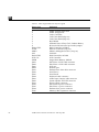
Table 1-1
Main Logic Board Parts Layout: Legend . . . . . . . . . . . . . . . . . .
5
Table 1-2
List of Acronyms . . . . . . . . . . . . . . . . . . . . . . . . . . . . . . . . . . . . . .
6
Table 1-3
Video Monitor Types . . . . . . . . . . . . . . . . . . . . . . . . . . . . . . . . . .
17
Table 2-1
Summary of Available Diagnostic Tool . . . . . . . . . . . . . . . . . . .
23
Table 2-2
Table of Memory Banks . . . . . . . . . . . . . . . . . . . . . . . . . . . . . . . .
28
Table 4-1
Table of Memory Banks . . . . . . . . . . . . . . . . . . . . . . . . . . . . . . . .
52
Table 4-2
Table of Hard Disk ID Jumper Settings . . . . . . . . . . . . . . . . . . .
62
Table 4-3
Main Logic Board Parts layout: Legend. . . . . . . . . . . . . . . . . . .
82
Table 4-4
List of Acronyms . . . . . . . . . . . . . . . . . . . . . . . . . . . . . . . . . . . . . .
83
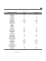
Table A-1
Regulatory Compliance Information . . . . . . . . . . . . . . . . . . . . . . .
103
Table A-2
Input Power Requirements and Power Dissipation for the
System Unit . . . . . . . . . . . . . . . . . . . . . . . . . . . . . . . . . . . . . . . . . . . .
104
Table A-3
Table of Environmental Requirements . . . . . . . . . . . . . . . . . . . . .
104
Table A-4
Table of Physical Specifications . . . . . . . . . . . . . . . . . . . . . . . . . . .
105
Table B-1
System Components and Their Part Numbers . . . . . . . . . . . . . . .
108
Table C-1
FRU List (continued on next page). . . . . . . . . . . . . . . . . . . . . . . . .
113
xi
xii
SPARCstation 2 Field Service Manual—February 1991
AboutThisBook
The SPARCstation 2 Field Service Manual describes how to diagnose system
problems by running diagnostic programs and removing and replacing field
replaceable units (FRUs). Appendix C lists the FRU part numbers.
Who Should Read This Book
This book is written for Sun Field Service representatives, original equipment
manufacturers (OEMs), value-added resellers (VARs), and other customers
with self-maintenance contracts.
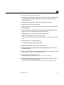
What This Book Contains
This book contains four chapters, four appendices and a glossary:
•
System Overview—Chapter 1
This chapter presents a high-level description of the SPARCstation 2 system,
followed by brief descriptions of each subsystem. Read this chapter to gain
a general familiarity with the hardware.
•
Diagnostics Overview—Chapter 2
This chapter describes the different types of diagnostics and how they are
related. This chapter also briefly discusses the Forth Toolkit. Read this
chapter to gain general knowledge about the diagnostic and Forth Toolkit
tools available to you.
xiii
•
Preparing to Work on the System—Chapter 3
This chapter explains how to halt the system, tools you will need, how to
disconnect the Desktop Storage Pack and the External Storage Module from
the system unit, how to remove the system unit’s top cover, and how to
attach a wrist strap to your wrist and to the system chassis. Read this
chapter before replacing any hardware.
•
FRU Replacement—Chapter 4
This chapter explains how to locate, remove, and replace defective fieldreplaceable units (FRUs) or install new ones. Drawings and callouts are
provided to illustrate the process. Read this chapter before attempting to
replace any hardware.
•
System Specifications—Appendix A
This appendix contains system specifications, including dimensions,
electrical and power requirements, environmental constraints, and
compliance with various electrical and safety regulations.
•
Illustrated Parts Breakdown—Appendix B
This appendix contains illustrations of global views of the system.
•
FRU list—Appendix C
This appendix contains the FRU list for SPARCstation 2.
•
OpenBoot PROM—Appendix D
This appendix contains the Alias and Boot Paths table and the Non-Volatile
Random Access Memory (NVRAM) parameters used during reset. These
parameters control the system configuration.
•
Glossary
The glossary contains definitions of technical terms, abbreviations, and
acronyms.
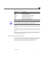
Before Reading This Book
Before reading this book, you should have performed hardware installation. If
you are connecting to a network, you should also be proficient with system
administration and networking procedures. If you are not proficient in these
areas, please read the following books before attempting to repair your system:
•
•
xiv
SPARCstation 2 Installation Guide
Sun System & Network Manager’s Guide
SPARCstation 2 Field Service Manual—February 1991
Typographic Conventions
This book uses a number of typographic conventions:
•
This font is used for emphasis and for the title of a book. For example:
The heart of the SPARCstation 2 is contained in a main chassis, or system
unit.
SPARCstation 2 Installation Guide
•
This font indicates text the system displays on the screen. This font
also indicates characters and words you enter (as shown within text).
Examples follow:
Syncing file systems... done
Enter passwd.
•
This font indicates what you type as illustrated in screen examples. For
example:
% sync
•
This font also indicates a key that you press. For example:
Press the Delete key.
When you see two key names, press and hold the first key, then type the
second character. For example:
When you see L1-A, press and hold L1, while typing A.
•
The term “enter” means to type the command indicated and press the
Return key. For example, “enter sync” means to type the command
indicated and press the Return key.
Related Books
The following books provide additional information that you may need, and
are occasionally referenced in this manual:
•
Open Boot PROM 2.0 Toolkit User’s Guide provides a summary of the Forth
Toolkit commands.
Preface
xv
xvi
•
Sundiag User’s Guide covers information about Sundiag, a system exerciser
that runs under the SunOS Operating System. Sundiag displays real-time
use of system resources and peripherals.
•
SPARCstation 2 Installation Guide provides step-by-step instructions on how
to install the system’s hardware and software.
•
Installing SPARCstation 2 SIMMs provides step-by-step information on how
to install SIMMs in the SPARCstation 2.
•
Installing SPARCstation 2 Internal Drives provides information on how to
install internal drives in the SPARCstation 2.
•
Sun System & Network Manager’s Guide describes system and network
management tasks for maintaining a single Sun workstation or a small
network of Sun workstations.
•
Desktop Storage Pack Installation Guide explains how to install and daisychain external storage modules.
•
External Storage Module Installation Guide provides step-by-step information
on how to install disk and tape drives that can be connected to a
SPARCstation 2.
•
Sun System User’s Guide covers the basics of using the SPARCstation 2 so
that you can get to work quickly. It will introduce you to the mouse and
keyboard, to SunView windows, and to the SunOS operating system.
•
SunDiagnostic Executive User’s Guide for SPARCstations explains how to run
extensive, configurable tests independent of SunOS. The Sun Diagnostic
Executive is the tool of choice when you need thorough diagnostics. With
the Sun Diagnostic Executive you can determine which field replaceable
unit needs to be replaced.
SPARCstation 2 Field Service Manual—February 1991
SystemOverview
1
This chapter presents an overview of the SPARCstation 2 system’s hardware.
This overview is helpful in servicing and maintaining hardware equipment.
The heart of the SPARCstation 2 is contained in a main chassis or system unit.
The system unit houses the main logic board. A power supply, two optional 3
1/2-inch hard disk drives, one optional 3 1/2-inch diskette drive, and the
speaker are also contained in the system unit. A frame buffer board or
graphics accelerator board must reside in one of the system’s three SBus
expansion slots when a video monitor is connected to the system. See “SBus
Boards” later in this Chapter for more information.
You can add expansion modules to increase the system’s mass storage capacity.
See “Mass Storage Devices” later in this chapter for more information on the
expansion modules.
The figures and tables covered in this chapter include the following:
•
Figure 1-1 illustrates the system’s configuration with an external storage
device.
•
•
•
•
•
Figure 1-2 presents the top view of the system with the cover removed.
Figure 1-3 presents the main logic board’s layout.
Table 1-1 gives the legends to be used with Figure 1-3.
Table 1-2 lists the acronyms used for certain parts, and their full expressions.
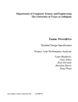
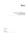
Figure 1-4 presents the block-level diagram of the main logic board. The
balance of the chapter describes the system’s components.
1
1
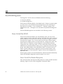
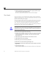
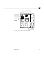
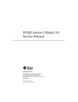
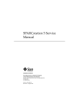
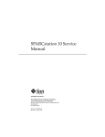
Figure 1-1 is a block diagram of one of the workstation’s configurations.
Monitor
Mouse
Keyboard
Power
supply
Tape
Main logic board
Hard disk
Internal
hard drive
System unit
Figure 1-1
2
SPARCstation 2 Block Diagram
SPARCstation 2 Field Service Manual—February 1991
Internal
diskette
drive
External storage
device
1
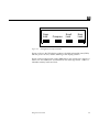
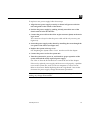
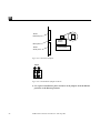
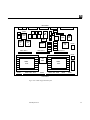
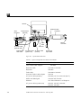
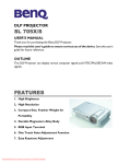
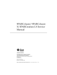
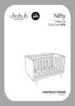
Figure 1-2 shows the top view of the system with the cover removed.
Boot
PROM
Lithium
battery
Serial port
jumpers
Back panel
SPARC floating
point unit (FPU)
SPARC integer
unit (IU)
Power
supply
SBus slots
SIMM
slots
Cache
controller
Hard
drive
1
Front panel
Figure 1-2
SIMM
slots
Hard
drive
2
Diskette
drive
Fan
System
assembly speaker
Top View of the System With the Cover Removed
System Overview
3
1
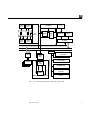
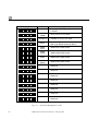
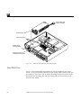
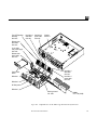
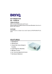
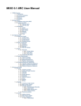
Figure 1-3 illustrates the main logic board’s layout. All the chips discussed in
“Main Logic Board,” which follows, are illustrated in this figure.
Back Panel
J0503 TTY B
J0502 TTY A
J0601 KBD
J0504
4
SPARC
FPU
5
1
J0404
6
7
J0403 SCSI
E-NET
8
E-NET
OSC
SPARC
IU
2
CACHE
Ctlr
3
MMU+
MMU+
SBus Slot 2
DMA
Ctlr
MMU+
MMU+
SBus Slot 3
SCSI
Ctlr
MMU+
J0705
MMU+
MMU+
SBus Slot 1
J0704
S4
RAM
J0701
SIMM
Slots
J0703
SIMM
Slots
J0402 HD1 SCSI
J0702
J0401 HD2 SCSI
Front Panel
Figure 1-3
4
The Workstation’s Main Logic Board
SPARCstation 2 Field Service Manual—February 1991
J0602
J0501
1
Table 1-1
Main Logic Board Parts Layout: Legend
Figure 1-3
Definition
1
2
3
4
5
6
7
8
DMA CTRL
E-NET
MMU+
OSC
RAM CTRL
SCSI Ctrl
SIMM
J0401
J0402
J0403
J0404
J0501
J0502
J0503
J0504
J0601
J0602
J0701
J0702
J0703
J0704
J0705
SPARC Floating Point Unit
SPARC Integer Unit
Cache Controller
Cache Data RAM (chip set)
Cache Data RAM (chip set)
Boot PROM
NVRAM, Time-of-Day Clock, Lithium Battery
RS-232 and RS-423 serial port mode jumpers
DMA Controller, S4 DMA+
Ethernet Controller (chip set)
Memory Management Unit+ (chip set)
Oscillator
RAM Controller, S4 RAM
SCSI Controller
Single Inline Memory Module
Hard Drive 2 SCSI cable connector
Hard Drive 1 SCSI cable connector
SCSI port
Ethernet port
Diskette Drive data cable connector
Serial Port A
Serial Port B
Keyboard cable connector
Audio Input/Output cable connector
System Speaker and LED connector
Power Supply connector
Hard Drive 2 power connector
Hard Drive 1 power connector
Diskette drive power connector
Memory/SBus expansion connector
System Overview
5
1
Table 1-2
6
List of Acronyms
Acronyms
Full Expression
DMA
MMU+
NVRAM
PROM
RAM
SCSI
SIMM
Direct Memory Access
Memory Management Unit+
Non-Volatile Random Access Memory
Programmable Read-Only Memory
Random Access Memory
Small Computer System Interface
Single Inline Memory Module
SPARCstation 2 Field Service Manual—February 1991
1
SPARC
FPU
SPARC
IU
S4 MMU+
S4
Cache+
Cache
data
64Kx8
16K
x
24
SIA
Ethernet
SCSI
S4 DMA+
Cache
data
SBus address
SBus data
Buffer
S4 RAM
Serial communication
controllers
16 SIMMs
S4
video
VRAM
SBus frame buffer board
Figure 1-4
I/O data bus
SBus
slots
Boot PROM
NVRAM/TOD
Diskette drive
controller
Audio
Block Level Diagram of the Main Logic Board
System Overview
7
1
Major Components
The system’s major components usually consist of the following:
•
•
•
•
•
The system unit
The keyboard
The video monitor (or a terminal)
The mouse
Optional external storage modules. The following are some of the external
storage modules available:
° Desktop Backup Pack 150 MB (megabyte) tape drive only
° Desktop Disk Pack 207 MB hard disk drive only
° Desktop SunCD Pack 644 MB (maximum) CD-ROM player only
° External Storage Module 327 MB hard disk drive only
° External Storage Module 327 MB hard disk drive and 150 MB cartridge
tape drive
° External Storage Module dual 327 MB hard disk drives
° External Storage Module 669 MB hard disk drive only
° External Storage Module dual 669 MB hard disk drives
° External Storage Module 669 MB hard disk drive and 150 MB cartridge
tape drive
° External Storage Module 669 MB hard disk drive and 2.3 GB cartridge
tape drive
° External Storage Module 2.3 GB cartridge tape drive only
These units may be daisy-chained together. For information on installing and
using external drive unit, see the Desktop Storage Pack Installation Guide.
Main Logic Board
The major sections of the main logic board consist of the following:
•
•
•
•
8
CPU core
SBus slots
Memory Management Unit+ (MMU+)
S4 Direct Memory Access+ (DMA+)
SPARCstation 2 Field Service Manual—February 1991
1
•
•
Dynamic Random Access Memory (RAM)
•
Eight-bit devices
Input/Output such as the Ethernet controller chip, the SCSI controller chip,
and the diskette drive controller chip
CPU Core
The CPU core consists of the following:
•
•
•
Integer Unit (IU)
Floating-point Unit (FPU)
Cache memory
These components are discussed in the sections that follow.
Integer Unit
The basic core of the main logic board is the SPARC Integer Unit (IU) (see
Figures 1-3 and 1-4). The IU’s clock speed is 40 MHz. The IU is supported
with the S4 chip set including the S4 cache+, the S4 memory management
unit+, the S4 buffer, and the S4 clock.
Floating-Point Unit
The floating-point unit (see Figures 1-3 and 1-4) delivers approximately 4.0
Mflops double-precision Linpack performance.
Cache Memory
Cache memory (see Figures 1-3 and 1-4) is high-speed local memory for the IU.
The chips comprising cache memory include the following:
•
•
S4 Cache+
Cache Data RAMs
The S4 cache chip serves as the SBus controller and the address path. The S4
buffer chip controls the data path through the cache. The S4 cache chip also
controls what data is available in the cache data RAMs.
System Overview
9
1
The IU asks for data from a specific address. That address is compared against
information stored in the cache tags. The S4 cache chip decides if the data the
IU is looking for is stored in the cache, based on the information stored in the
cache tags.
If the data is in the cache, the cache data RAM transmits data to the IU as fast
as the IU can receive data. If the data is not in the cache, this is referred to as
a cache miss, and the IU is halted. An SBus cycle is initiated to obtain the
required data from main memory. The cache data RAM is filled with the
information obtained from main memory and the IU is started again.
The cache design implemented in the SPARCstation 2 is a 64 K write-through
cache with one level of write buffering. The cache line size is 16 bytes, with
one tag for each line.
SBus Slots
There are three SBus slots on the main logic board (see Figures 1-2 and 1-3).
SBus boards such as frame buffer board, a GX graphics accelerator board, or a
second ethernet board are installed in the SBus slots.
The SBus slots are connected to the SBus data bus and the SBus address bus.
The SBus is a proprietary 32-bit synchronous bus. See “SBus Boards” later in
this chapter for more information on specific SBus boards. “SBus Boards” in
Chapter 4 explains how to remove and replace SBus boards.
Memory Management Unit+
The S4 memory management unit+ (MMU+) chip (see Figures 1-3 and 1-4) is
connected to the system bus. The MMU+ maps the virtual addresses used by
user programs, SunOS, and input/output devices to physical memory
addresses. This is how virtual memory is implemented. Virtual memory
allows a user program to have access to an address space that is larger than the
physical memory present on the system.
In addition, it isolates the address space of one process from that of another,
preventing errors in a user-level program from bringing the entire system
down. It also controls the protections (read-only or read/write) associated
with each page of memory, allowing, for example, one copy of a shared library
to be used by many running programs.
10
SPARCstation 2 Field Service Manual—February 1991
1
S4 DMA+
Ethernet is controlled by a Local Area Network Controller for Ethernet
(LANCE) controller chip (see Figures 1-3 and 1-4). It interfaces to the SBus
through the S4 DMA+ chip. SCSI disk drive operations are handled through
the SCSI controller chip. It also interfaces to the SBus through the S4 DMA+
chip.
Dynamic RAM
The Dynamic RAM (DRAM), is comprised of the following:
•
•
One S4 RAM chip, illustrated in Figures 1-3 and 1-4.
16 Single Inline Memory Module (SIMM) slots for 4 MB SIMMs in groups
of 4. See “Single Inline Memory Modules (SIMMS)” in Chapter 4 and
Installing SPARCstation 2 SIMMs for information on how to install SIMMS.
Input/Output
The following chips, which control input/output devices, are briefly discussed
in this section:
•
•
•
Ethernet (LANCE) controller chip
SCSI controller chip
Diskette drive controller chip
Ethernet is controlled by a Local Area Network Controller for Ethernet
(LANCE) controller chip (see Figures 1-3 and 1-4).
The SCSI hard disk drives are controlled by the SCSI controller chip (see
Figures 1-3 and 1-4).
The diskette drive is controlled by the diskette drive controller chip (see
Figure 1-4).
System Overview
11
1
Eight Bit Devices
The eight-bit devices connected to the I/O data bus consist of the following:
•
Boot PROM
The boot PROM (see Figures 1-3 and 1-4) is connected to the I/O data bus.
The boot PROM is 256Kx8 in size and contains the boot code, diagnostics,
and the Forth Toolkit, signified by the ok prompt. The Forth Toolkit does
not look like other Sun Monitor programs and does not behave like the
older Sun PROMs.
The boot PROM does the following:
a. Runs startup diagnostic tests.
b. Initializes the host machine.
c. Reads non-volatile RAM (NVRAM) and executes the boot sequence.
Usually, this consists of booting SunOS. In some cases, however, the
SunDiagnostic Executive or standalone programs can also be run. For
more information on the boot sequence, see “How It Fits Together” in
Chapter 2.
d. Supplies program code for the abbreviated system monitor, signified by
the > prompt and the Forth Toolkit. If the boot attempt fails, the boot
PROM tries to start the abbreviated system monitor.
e. Supplies program code for the on-board diagnostics accessible through
the Forth Toolkit. For more information on the on-board diagnostics, see
“Boot PROM Diagnostics” in Chapter 2.
•
Non-volatile RAM (NVRAM) and Time-of-Day Clock
The NVRAM chip (see Figures 1-3 and 1-4) contains the time-of-day clock
and the non-volatile RAM. The NVRAM chip is connected to the I/O data
bus.
The NVRAM chip contains its own battery. There is no limit on the number
of times the NVRAM chip can be written to.
The non-volatile RAM stores the default system configuration parameters.
The default parameters are listed in Appendix D. This defines how the
system will be set up at the lowest level. You can modify these parameters
12
SPARCstation 2 Field Service Manual—February 1991
1
using the Forth Toolkit. If you need to change these parameters, see
“Appendix B, NVRAM Configuration Parameters Summary” in the Open
Boot PROM 2.0 Toolkit User’s Guide.
•
Serial Ports A and B
Serial ports A and B are provided on the main logic board (see Figure 1-3).
These serial ports are RS-423 or RS-232 ports and can connect peripheral
equipment such as terminals, printers, and modems. The serial ports on the
SPARCstation 2 are set to operate in synchronous or asynchronous RS-423
mode.
The serial ports can be reconfigured by changing jumpers on the main logic
board to run at RS-232 for users in the Federal Republic of Germany. Both
ports must be configured for either RS-423 or RS-232 mode. The serial
communications controller chips (see Figure 1-4) help to implement the
serial port A and B interface. Refer to Chapter 4 “Main Logic Board” for
information on how to set the serial port jumpers.
•
Keyboard and Mouse Interface
A keyboard port, on the back of the main logic board to the left of the Serial
B port (see Figure 1-3), controls the keyboard and mouse. The serial
communications controller chips (see Figure 1-4) help to implement the
keyboard and mouse interface.
•
Diskette Drive Controller
The internal diskette drive is connected to the I/O data bus by the diskette
drive controller chip (see Figure 1-4).
•
Audio
The system speaker is connected to the I/O data bus by the audio chip (see
Figure 1-4). There is one audio port on the back panel. You can plug the
following devices into the audio input/output port:
°
°
°
°
°
°
Dynamic, high-impedance microphone (10,000 ohms to 50,000 ohms
impedance)
Dynamic, low-impedance microphone (300 ohms to 1000 ohms
impedance)
Audio tape player equipped with attenuating adapter
Compact disc player equipped with attenuating adapter
Headphones (30 ohms to 100 ohms impedance)
External amplifier and loudspeaker
System Overview
13
1
The workstation’s sound capabilities can be shown with Soundtool, an
audio demonstration program included with SunOS. To test the
workstation’s sound, see “Speaker” in Chapter 4. For additional
information, see “SunOS Features” in Chapter 6 of the SPARCstation 2
Installation Guide, and “Appendix C” in the Sun System User’s Guide.
Single Inline Memory Modules (SIMMs)
At present, up to 64 MBs of memory, contained in 4 MB Single Inline Memory
Modules (SIMMs), can be added in increments of 16 MBs (see Figures 1-2, 1-3,
and 1-4). See “Single Inline Memory Modules (SIMMs)” in Chapter 4 for
SIMM installation and removal instructions. Also refer to Installing
SPARCstation 2 SIMMs.
SBus Boards
Various SBus boards can be added to the system’s three SBus slots on the main
logic board. Figures 1-2, 1-3 and 1-4 illustrate the SBus slots. See “SBus
Boards” in Chapter 4 for information on how to remove and replace SBus
boards. The following is a list of some of SBus boards available for a
SPARCstation 2. Note that this is not an inclusive list of all SBus boards
available for the SPARCstation 2.
14
•
GX Graphics Accelerator Board
This board controls the video output from the system unit, and accelerates
the generation of graphic images. The GX Graphics Accelerator board
occupies two SBus slots on the main logic board.
•
Color Frame Buffer Board
This board occupies one SBus slot. This board controls the video output
from the system unit to a color monitor.
•
Second Ethernet Board
This board provides you with an extra Ethernet port. The Ethernet board is
used in applications in which your SPARCstation 2 acts as a gateway
between two physically distinct Ethernet networks. This board has two
connectors: standard (thick) Ethernet and thin Ethernet, and occupies one
SBus slot.
SPARCstation 2 Field Service Manual—February 1991
1
•
GS Graphics Accelerator Board
This option consists of two boards that are plugged to each other on their
component sides. They are triple-wide SBus boards and occupy three SBus
slots. Figure 4-2 shows the top side of GS Graphics Accelerator Board when
it is installed in the system unit. This option provides 24-bit color and 3
dimensional graphics capabilities. It also requires a 76 Hz color monitor.
•
Video Frame Capture Board
This board occupies one SBus slot. This board takes video input and
displays it on color or monochrome monitors.
•
SBus Printer Card
This board occupies one SBus slot. This board connects the system to
printing, plotting and scanning devices.
•
1-Bit Analog Frame Buffer Board
This board occupies one SBus slot. It controls the video output from the
system to a monochrome monitor.
Mass Storage Devices
The following is some of the mass storage devices available. Note that the
following list is not necessarily an inclusive list of mass storage devices
available for SPARCstation 2.
•
Hard disk drives
Two optional 3 1/2-inch SCSI 207 MB hard disk drives (see Figure 1-2) can
be installed in the system unit. Chapter 4 describes how to replace the
optional hard disk drives in the system unit.
•
Optional expansion modules. The following are available:
Desktop Storage Packs (DSPs)
°
°
°
Desktop Backup Pack 150 MB SCSI-compatible tape drive only
Desktop Disk Pack 207 MB hard disk drive only
Desktop SunCD Pack 644 MB (maximum) CD-ROM only
External Storage Modules (ESMs)
° External Storage Module 327 MB hard disk drive only
° External Storage Module 327 MB hard disk drive and 150 MB cartridge
tape drive
° External Storage Module dual 327 MB hard disk drives
System Overview
15
1
°
°
°
°
°
•
External Storage Module 669 MB hard disk drive only
External Storage Module dual 669 MB hard disk drives
External Storage Module 669 MB hard disk drive and 150 MB cartridge
tape drive
External Storage Module 669 MB hard disk drive and 2.3 GB cartridge
tape drive
External Storage Module 2.3 GB cartridge tape drive only
These units may be daisy-chained together. By attaching optional
expansion units, you can increase the system’s mass storage capacity.
For information on installing and using external drive units, see the
Desktop Storage Pack Installation Guide or the External Storage Module
Installation Guide.
Diskette drive
An optional 3 1/2-inch 1.44 MB internal diskette drive (see Figure 1-2) can
be installed in the system unit. The drive accepts a 4-pin AMP power
connector and a 34-pin data cable. The data transfer rate is 1 Mbps (Mbit per
second). “Diskette Drive” in Chapter 4 describes how to remove and
replace the optional diskette drive in the system unit.
Power Supply
The power supply (see Figure 1-2) is housed in the system unit. It connects to
the system via a 12-pin connector and provides +5, +12, and -12 volts DC.
Voltages are regulated. The power supply also supplies the power-on reset
signal.
Some of the power supply’s features include the following:
•
•
•
•
Switching power supply
Overcurrent protection
Crowbar feature
Internal fusing
The External drive units have their own power supplies. The External Storage
Module’s power supply provides +5, +12, and -12 volts DC. The Desktop
Storage Pack’s power supply provides +5 and +12 volts DC.
16
SPARCstation 2 Field Service Manual—February 1991
1
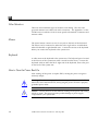
Monitors
Each system accepts a keyboard, an optical mouse, and one of several types of
video monitors.
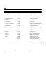
See Appendix C for the available monitors. See Table 1-3 for the supported
monitors.
Table 1-3
Video Monitor Types
Monitor Type
Voltage
16-inch color monitor (407 mm)
115 V
16-inch color monitor (407 mm)
240 V
19-inch standard grayscale monitor (483 mm)
19-inch high-resolution monochrome
90-240 V
115 V
monitor (483 mm)
19-inch high-resolution monochrome
monitor (483 mm)
17-inch grayscale (432 mm)
240 V
90-240 V
19-inch Sony color monitor (483 mm)
115 V
19-inch Sony color monitor (483 mm)
240 V
16-inch color overscan monitor (407 mm)
90-240 V
19-inch color overscan monitor (483 mm)
90-240 V
17-inch grayscale overscan monitor (432 mm)
90-240 V
19-inch grayscale overscan monitor (483 mm)
90-240 V
System Overview
17
1
18
SPARCstation 2 Field Service Manual—February 1991
DiagnosticsOverview
2
This chapter describes the different types of diagnostic firmware and software
tools available to you and how they are related. The main categories of
diagnostics are:
•
Boot PROM diagnostics
° Power-On Self-Test (POST)
° On-Board Diagnostics
•
•
Sundiag System Exerciser
SunDiagnostic Executive
Besides these categories of diagnostics, this chapter briefly covers the Forth
Toolkit, which is an interactive command interpreter based on the Forth
programming language. For a more complete discussion of the Sun Forth
Toolkit, see the Open Boot PROM 2.0 Toolkit User’s Guide.
The Forth Toolkit gives you access to an extensive set of functions for
performing the following:
•
•
•
•
Hardware development
Problem determination (fault isolation)
Software development
Debugging
All functions available through the Monitor > prompt, except entering the
Forth Toolkit, are also available through the Forth Toolkit.
19
2
The flowchart in Figure 2-1 outlines the roles played by various diagnostics
during the default boot mode.
Power on switch
Low level post
Display errors
on keyboard
LEDs
No
POST
passed
Yes
Probe SBus devices
and interpret their drivers.
High level tests. You will
see Testing when these
tests are run.
Auto-boot?
No
L1-A to get to
the > or ok prompt
> or ok prompt
b command at >
prompt or boot
command at ok
prompt
Yes (default)
Yes
Diag
switch?
No (default)
Boot from
device path
/sbus/le
Figure 2-1
20
Boot from
device path
/sbus/esp
/sd@3,0
Boot userspecified
program
Default Boot Mode
SPARCstation 2 Field Service Manual—February 1991
2
How It Fits Together
This section describes how the various diagnostic tools work together in the
different power-on modes. This description assumes you are using a graphics
monitor to view test results. The flowchart in Figure 2-1 outlines the roles
played by various diagnostics during the default boot mode.
When you turn on system power, the low-level POST code, stored in the boot
PROM, is executed. While low-level POST code is executing, you will see the
four LEDs on the keyboard flashing to indicate that testing is in progress. If a
failure occurs in POST, the failing field replaceable unit (FRU) is encoded on
the four LEDs located on the Type-4 keyboard. See “Power-On Self-Test” later
in this chapter for more information.
If the POST passes, the system probes for SBus devices and interprets their
drivers. Next, high level tests are performed. You will see the word Testing
while the high level tests are running. After Testing is displayed, if you
want to enter the Monitor, (indicated by the > prompt), press the L1-A keys
simultaneously.
If the autoboot switch parameter is set to false (not the default), you will obtain
either the > or ok prompt. The > prompt is the default prompt. You can
change the default prompt to obtain the ok prompt, the Forth Toolkit prompt,
as the default. To make the ok prompt the default prompt, see the Open Boot
PROM 2.0 Toolkit User’s Guide.
If the autoboot switch parameter is set to true (default), and the diagnostic
switch parameter is set to false (default), SunOS is booted using the device
path /sbus/esp/sd@3,0. If the autoboot switch parameter is set to true
(default), and the diagnostic switch parameter is set to true (not the default),
SunOS is booted using the device path /sbus/le.
To boot user-specified programs, such as the SunDiagnostic Executive, you
must be at the > or ok prompt. See “On-Board Diagnostics” later in this
chapter for a detailed procedure on how to obtain the > and ok prompts.
Diagnostics Overview
21
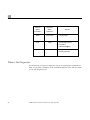
2
Autoboot
Switch
Parameter
Diagnostic
Switch
Parameter
False
(Don't care)
True
False
boot SunOS (vmunix)
from disk 0*
(/sbus/esp/sd@3,0)
True
True
boot SunOS (vmunix) from
network* (/sbus/le)
Results
> or ok prompt
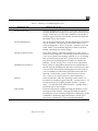
When to Use Diagnostics
You should use each type of diagnostic tool in the appropriate circumstances.
Table 2-1 provides a summary of the available diagnostic tools, and lists when
to use each diagnostic tool.
22
SPARCstation 2 Field Service Manual—February 1991
2
Table 2-1
Summary of Available Diagnostic Tool
Diagnostic Tool
When or why to use
Power-On Self-Test
Executes automatically at power-on. The POST code resides in
the boot PROM and is driven by the Por signal from the power
supply. POST tells you if the major hardware components of
the main logic board, the frame buffer, and the hard disk fails.
Described later in this chapter.
On-Board Diagnostics
Test such as the Ethernet test, and the diskette drive controller
test are available. You must be in the Forth Toolkit to run
on-board diagnostics. Enter n from the > prompt to enter the
Forth Toolkit. The On-Board diagnostics reside in the boot
PROM. Described later in this chapter.
Sundiag System Exerciser
Runs under SunOS. It displays real-time use of the system
resources and peripherals. The Sundiag System Exerciser tells
you if your system is functioning correctly or not. If Sundiag
fails, run the Power-On Self-Test. If all power-on self-tests
pass, then run the SunDiagnostic Executive to identify the
problem. See the Sundiag User’s Guide for more information.
SunDiagnostic Executive
Runs extensive, configurable subsystem tests independent of
SunOS. Run the SunDiagnostic Executive if all tests pass when
you run POST. Running the SunDiagnostic Executive allows
you to troubleshoot which field replaceable unit needs to be
replaced. See the latest version of SunDiagnostic Executive
User’s Guide for the SPARCstations for more information.
Monitor
Enters the Monitor when the operating system crashes. To
bot SunOS or another program from the > prompt, enter b. To
resume execution of a halted program from the > prompt,
enter c. To enter the Forth Toolkit from the > prompt, enter n.
Described later in this chapter.
Forth Toolkit
Performs all functions available through the Monitor, except
entering the Forth Toolkit. Changing NVRAM parameters.
Resetting the system. Running diagnostics. Displaying system
information. Redirecting input and output. See the Open
Boot Prom 2.0 Toolkit User’s Guide for more information.
Diagnostics Overview
23
2
Boot PROM Diagnostics
The diagnostics stored in the boot PROM include the following:
•
•
Power-On Self-Test
On-Board Diagnostics
The Power-On Self-Test (POST) is the default mode. If there is system trouble,
you may want to run extended on-board diagnostics to take advantage of
thorough tests including — but not limited to — Ethernet, memory, and
diskette drive tests. See Figure 2-3 for the table of keyboard LED diagnostic
codes.
The boot PROM diagnostics are described in the following sections.
Power-On Self-Test (POST)
The Power-On Self-Test (POST) runs automatically when you turn on the
system’s power switch or reboot the system. The POST code, which resides in
the boot PROM, is executed by the CPU (IU) when the Por signal is received
from the power supply. Por is a Power-On reset TTL open collector signal
from the power supply, which is activated after DC voltages have risen. The
POST consists of a sequence of tests designed to test the major hardware
components of the main logic board, in a short time before SunOS is booted.
POST does not perform extensive testing on any component of the main logic
board. Only major failures can be detected by POST. If a failure occurs in
POST, a specific LED pattern is displayed on the four LEDs located on the
upper right corner of your keyboard. Figure 2-2 shows the arrangement of
keyboard LEDs.
Following the system’s successful initialization, SunOS is booted automatically,
unless the NVRAM configuration options specify not to do so.
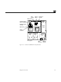
Power-On Self-Test Detailed Description
This section describes the keyboard LED patterns as a result of POST and their
meaning. Figure 2-2 shows the arrangement of keyboard LEDs.
24
SPARCstation 2 Field Service Manual—February 1991
2
Caps
Lock
Figure 2-2
Compose
Scroll
Lock
Num
Lock
Arrangement of Keyboard LEDs
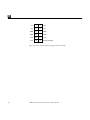
Figure 2-3 shows the LED display patterns, the field replaceable units (FRUs)
that fail power-on tests, and the meaning of the display patterns.
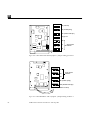
Figure 2-4 shows the location of the SIMM slots in the system unit. Figure 2-5
shows how the SIMM slots are identified on the main logic board. Table 2-2
identifies memory banks and slots.
Diagnostics Overview
25
2
LED Display Pattern
FRU
Boot
PROM
NVRAM/TOD
Main Logic
Board
Meaning of Pattern
Unassigned. Testing completed, SunOS
is booted.
Bad checksum in boot PROM.
NVRAM/Time-of-Day Clock failed.
Main Logic Board component failed.
SIMM
U0311
SIMM U0311 failed, bank 0.
SIMM
U0309
SIMM U0309 failed, bank 0.
SIMM
U0307
SIMM U0307 failed, bank 0.
SIMM
U0322
SIMM U0322 failed, bank 0.
Reserved
Reserved
Reserved
Reserved
Reserved
Reserved
Reserved
Reserved
Figure 2-3
26
Keyboard LED Diagnostic Codes
SPARCstation 2 Field Service Manual—February 1991
2
Boot
PROM
Lithium
battery
Serial port
jumpers
Back panel
SPARC floating
point unit (FPU)
SPARC integer
unit (IU)
Power
supply
SBus slots
SIMM
slots
Cache
controller
Hard
drive
1
Front panel
Figure 2-4
SIMM
slots
Hard
drive
2
Diskette
drive
Fan
System
assembly speaker
Location of SIMM Slots in System Unit
Diagnostics Overview
27
2
SBus slots
U0311
U0322
U0312
U0321
U0313
U0320
U0319
U0316
U0309
U0307
(U0310)
U0308
(U0314)
U0315
(U0318)
U0317
Hard drive(s)
Figure 2-5
Table 2-2
SIMM Slot Locations on Main Logic Board
Table of Memory Banks
Bank:
Slots:
0
U0311
U0309
U0322
U0307
1
U0312
(U0310)
U0321
U0308
2
U0313
(U0314)
U0320
U0315
3
U0319
(U0318)
U0316
U0317
Note – Slots U0310, U0314, and U0318 are not identified on the board with any
visible markings. These slots are shown in Figure 2-5 andTable 2-2 in parentheses.
28
SPARCstation 2 Field Service Manual—February 1991
2
For further information about replacing the FRUs that fail, see “Removing and
Replacing FRUs” in Chapter 4.
If all POST tests pass, run the SunDiagnostic Executive with the cache
disabled. The SunDiagnostic Executive is an independent operating system. It
runs exhaustive subsystem tests independent of SunOS. See the latest version
of SunDiagnostic Executive User’s Guide for the SPARCstations.
On-Board Diagnostics
You have access to a number of tests called On-board diagnostics. To invoke
these tests, you must enter the Forth Toolkit.
!
Caution – In order to run On-board diagnostics, you must halt the system in
an orderly manner. When the operating system or any other stand-alone
program has already booted, do not use the L1-A keys to halt the system.
Abruptly aborting program execution may cause damage to data files.
To run On-board diagnostics:
1. Save all your work and quit all applications.
2. As root, halt the system by entering /usr/etc/fasthalt.
You are presented with either the > prompt or the ok prompt. The >
prompt is the default prompt. If you want to change the default prompt to
the ok prompt, see the Open Boot PROM 2.0 Toolkit User’s Guide.
If you see the > prompt, go to the next step. If you see the ok prompt, go
to Step 4.
3. Enter n to enter the Forth Toolkit.
The ok prompt shows that you are in the Forth Toolkit.
4. Enter help diag to get a listing of tests comprising on-board
diagnostics.
Diagnostics Overview
29
2
Figure 2-6 summarizes the steps you need to take to halt the system, enter the
Forth Toolkit, and list the diagnostic tests.
hostname#
/usr/etc/fasthalt
..... system messages are displayed
> n
ok help diag
Category: Diag (diagnostic routines)
test
device-specifier ( -- ) run selftest method for specified device
Examples:
test /memory
- test memory
test /sbus/le
- test net
test net
- test net (device-specifier is an alias)
test floppy
- test floppy disk drive
watch-clock
(--)
show ticks of real-time clock
probe-scsi
(--)
show attached SCSI devices
Figure 2-6
Halting the System and Displaying On-Board Diagnostics
These on-board tests allow you to test the network controller, the diskette drive
system, memory and the system clock. See “Diagnostic Routines” in the Open
Boot PROM 2.0 Toolkit User’s Guide for a detailed description and step-by-step
instructions of the available on-board diagnostic tests.
To return to the Monitor, > prompt, enter the following:
ok
>
old-mode
Sundiag System Exerciser
The Sundiag System Exerciser, which runs under SunOS, displays real-time use
of system resources and peripheral equipment such as Desktop Storage Packs
and External Storage Modules. The Sundiag System Exerciser is run to verify
that the system is functioning properly.
The exerciser is shipped with SunOS and preinstalled on SPARCstation 2. If it
has been selected during the SunInstall (operating system loading) procedure,
it can be run at any time and is found in the directory /usr/diag/sundiag.
If the Sundiag System Exerciser is not found on the system hard disk or server,
30
SPARCstation 2 Field Service Manual—February 1991
2
you can load it from tape or CD. For information on how to use the Sundiag
System Exerciser, see the Sundiag User’s Guide. Appendix A, “Loopback
Connectors” in the Sundiag User’s Guide explains how to connect the external
loopback connectors required for some options. If Sundiag passes, the system
is operating properly. If Sundiag fails, the system is not operating properly. To
identify the problem when Sundiag fails, first run the POST. If all POST tests
pass, next run the SunDiagnostic Executive to isolate the problem.
SunDiagnostic Executive
The SunDiagnostic Executive is an independent operating system. It runs
exhaustive subsystem tests independent of SunOS. Run the SunDiagnostic
Executive if all POST tests pass in order to troubleshoot what field-replaceable
unit needs to be replaced. For information on POST, see “Power-On Self-Test
Detailed Description” earlier in this chapter. The SunDiagnostic Executive,
which provides you with thorough diagnostics, is described in the
SunDiagnostic Executive User’s Guide for the SPARCstations.
Monitor and Forth Toolkit
The Monitor is a basic diagnostic utility. If there is any problem with your
operating system, the Monitor automatically starts, indicated by the >
prompt. You can also choose to enter the Monitor by halting the system. To
enter the Forth Toolkit, indicated by the ok prompt, enter n from the >
prompt.
The following procedure explains how to enter the Monitor and the Forth
Toolkit:
1. Save all your work and quit all applications.
The following screen summarizes the steps you need to take to halt the
system and enter the Forth Toolkit.
hostname# /usr/etc/fasthalt
syncing file systems .... done
Halted
Type b (boot), c (continue) or n (new command mode)
> n
Diagnostics Overview
31
2
2. As root, enter /usr/etc/fasthalt.
The system syncs the file systems and brings you to either the > or ok
prompts. The > prompt is the default prompt. You will see the ok
prompt if you reset the system parameters to have the ok prompt, the
Forth Toolkit prompt, as the default prompt.
For Non-Volatile RAM system configuration parameters used during reset,
see Appendix D. To have the ok prompt as the default, see the Open Boot
PROM 2.0 Toolkit User’s Guide. If you see the ok prompt, you are already
in the Forth Toolkit and need to do nothing further. If you see the >
prompt, go to the next step.
3. Enter n to enter the Forth Toolkit.
The ok prompt shows that you are in the Forth Toolkit.
For extensive information on tests you can run from the Forth Toolkit see
Chapter 5 of the Open Boot PROM 2.0 Toolkit User’s Guide.
To return to the Monitor > prompt, from the Forth Toolkit:
ok old-mode
>
32
SPARCstation 2 Field Service Manual—February 1991
PreparingtoWorkontheSystem
3
This chapter explains steps you must perform before replacing fieldreplaceable-units (FRUs). Topics covered in this chapter include the following:
•
•
•
•
•
•
How to halt the system
Tools needed
How to disconnect the Desktop Storage Pack
How to disconnect the External Storage Module
How to remove the system unit’s cover
How to attach a wrist strap
Halting the System
Before you replace FRUs, you must halt the system in an orderly manner.
!
Caution – You must halt the system in an orderly manner. When the operating
system or any other stand-alone program has already booted, do not use the
L1-A keys to halt the system. Abruptly aborting program execution may cause
damage to data files.
33
3
To halt the system:
1. Save any files you are presently editing. Quit from any applications that
will lose information when the system halts.
See the Sun System User’s Guide for more information about ending a work
session.
2. Enter /bin/su to become superuser.
Additional information about the superuser command is described in
Chapter 2 of the Sun System & Network Manager’s Guide.
3. Enter the superuser password.
4. Enter /usr/etc/halt.
The system displays system halt messages followed by the Monitor
prompt, >.
tutorial% /bin/su
Password:
tutorial# /usr/etc/halt
Syncing file systems... done
Halted
Type b (boot), c (continue), or n (new command mode)
>
5. Turn off the power in this order:
° External module (if you have one)
° System unit
° Monitor
!
34
Caution – Make sure your system is shut off. The green LED at the front of the
system unit should not be lit, and the fans should not be running. Do not
disconnect the power cord from the system unit’s power outlet or the wall
socket. This connection provides the ground path necessary to safely remove
and install the printed circuit boards and components.
SPARCstation 2 Field Service Manual—February 1991
3
Margin note
On some keyboards, L1 appears
on the front face of the Stop key.
On a system that has a terminal
as a console, rather than a Sun
keyboard and bitmapped monitor,
you must press Break instead of
L1-A to obtain a boot prompt.
To halt a system that is hung, or frozen, and unresponsive to commands:
1. Press L1-A.
The system displays the system boot prompt.
2. Enter n.
The system displays a help message and an ok prompt.
3. Enter sync.
The system displays panic and boot messages. The sync command helps
prevent the system from losing data that was not preserved when the
system hung.
4. Wait until the system boots and displays a system login prompt.
5. Turn off the power in this order:
° External drive unit (if you have one)
° System unit
° Monitor
The following example shows how to halt a hung system:
(Press L1-A.)
> n
Type help for more information
ok sync
(System panic and boot messages.)
tutorial login:
For additional information on the halt procedure see Chapter 1 of the Sun
System & Network Manager’s Guide and also the System & Network Administration
manual.
!
Caution – Make sure your system is shut off. The green LED at the front of
the system unit should not be lit, and the fans should not be running. Do not
disconnect the power cord from the system unit’s power outlet or the wall
socket. This connection provides the ground path necessary to remove and
install the printed circuit boards and component.
Preparing to Work on the System
35
3
Tools Needed
To remove and replace FRUs, you will need the following tools and materials:
•
•
•
•
•
•
•
•
•
Phillips screwdriver
Flat blade screwdriver
Wrist strap
SIMM extractor
Chip extractor
Container for screws
Anti-static mat for the SIMMs and the main logic board
Nonconductive foam to store chips
A Volt-Ohmmeter (VOM) for checking voltages and fuses
Disconnecting Desktop Storage Packs
If your system unit has Desktop Storage Packs connected to it, disconnect the
Desktop Storage Packs’ SCSI connector from the back of the system unit.
To disconnect the Desktop Storage Pack from the system unit:
1. Press in on the finger clips on the connector connecting the Desktop
Storage Pack to the system unit and pull the connector off.
This action disconnects the SCSI cable from the system unit.
Disconnecting External Storage Modules
If your system unit has External Storage Modules connected to it, disconnect
the External Storage Modules’ SCSI connector from the system unit.
To disconnect the External Storage Module (ESM) from the system unit:
1. Press in on the finger clips on the connector connecting the ESM to the
system unit and pull the connector off.
This action disconnects the SCSI cable from the system unit.
36
SPARCstation 2 Field Service Manual—February 1991
3
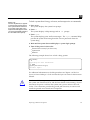
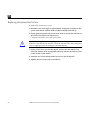
Removing the System Unit’s Cover
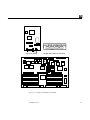
Figure 3-1 shows how to remove the system unit’s cover. Three tabs on the
front of the cover fit into three slots in the chassis. These tabs secure the front
of the cover to the chassis. A security loop secured to the cover goes through
the bottom of the chassis.
To remove the cover and gain access to the FRUs inside the system unit:
1. Make sure that the power is turned off to your system unit, but that the
power cord remains plugged in to the system unit and to the power
source.
See “Halting the System” earlier in this chapter.
2. Remove the top cover from the system unit.
Do the following in sequence:
°
°
°
°
Remove the two screws holding the cover to the back panel (see
Figure 3-1).
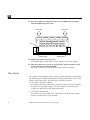
Grasp the sides of the cover from the rear and tilt the cover until the
security loop clears the chassis (see Figure 3-2).
Gently push the cover forward about 1/2 inch (13 mm) so that the plastic
tabs clear the chassis.
Remove the cover by lifting vertically.
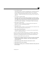
Warning – Before powering up your system again, be sure to replace the top
cover. See “Replacing the System Unit’s Cover” towards the end of Chapter 4.
It is not safe to operate the SPARCstation 2 without its top cover in place
Preparing to Work on the System
37
3
1
3
4
2
5
Note: There are five screws on the back panel. Remove
screws 1 and 2. Do not remove screws 3, 4, and 5.
Figure 3-1
System Unit Back Panel
Security loop
Plastic tabs
Remove these two
screws from back panel
Figure 3-2
38
The System Unit’s Cover
SPARCstation 2 Field Service Manual—February 1991
3
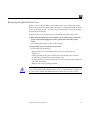
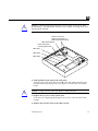
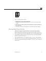
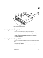
Attaching a Wrist Strap
The wrist strap is a device that provides grounding between your body and the
system unit’s chassis for static electricity. Electric current and voltage do not
pass through the wrist strap. Attach the wrist strap to your wrist and to the
system chassis. Parts that require the use of a wrist strap are packed with one.
!
Caution – Boards and modules can be damaged by harmful electrical charges if
you do not wear a wrist strap
To attach the wrist strap:
1. Wrap the grounding strap with the conductive adhesive tape twice around
your wrist.
Make sure the adhesive side is against your skin.
Attach end to metal
casing of power supply
Wrap the wrist strap twice around your
wrist (adhesive against your skin).
2. Attach the end with the adhesive copper strip to the metal casing of the
power supply in the system unit.
Preparing to Work on the System
39
3
40
SPARCstation 2 Field Service Manual—February 1991
FRUReplacement
4
This chapter explains how to remove defective FRUs and replace new ones.
See “FRU list” in Appendix C for the part numbers and description of FRUs.
The following units are field-replaceable:
•
•
•
•
•
•
•
•
•
•
•
•
•
•
Single Inline Memory Modules (SIMMs)
SBus boards
Power supply
Hard disk drives
Diskette drive
Fan assembly
Main logic board
Boot PROM
NVRAM/TOD clock
System speaker
Video monitors
Mouse, mouse pad and cable
Keyboard
Cables
FRU replacement described in the manuals for the Desktop Storage Pack and
the External Storage Module are not covered in this manual.
41
4
Before You Begin
Before you replace FRUs, make sure you have done the following:
•
•
•
•
•
Halted your system
Verified that you have the proper tools
Removed the expansion units (if any)
Removed the system unit’s cover
Attached a wrist strap
See Chapter 3 for further information.
Removing and Replacing FRUs
This section describes how to remove and replace FRUs. Please read through
the entire set of instructions before removing and replacing a FRU.
!
Caution – Make sure your system is shut off. The green LED at the front of the
system unit should not be lit, and the fans should not be running. Do not
disconnect the power cord from the system unit’s power outlet or from the wall
socket. This connection provides the ground path necessary to safely remove
and install the printed circuit boards and components.
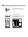
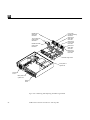
FRU Identification
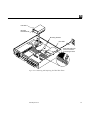
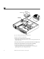
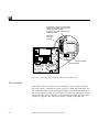
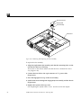
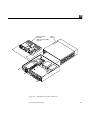
Before you attempt to replace or install a new board or module, make sure that
you have the right unit. Figure 4-1 shows a top view of the system unit with
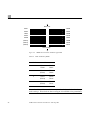
the cover removed. Figure 4-2 shows some of the field-replaceable boards and
the memory module. There are other field-replaceable boards that are
available but not shown in Figure 4-2.
!
Caution – Printed circuit boards are made of delicate electronic components that
are extremely sensitive to static electricity. Ordinary amounts of static from your
clothes or work environment can destroy the boards.
Handle boards only by the non-conducting edges. Do not touch the
components themselves or any metal parts. Wear a grounding strap when
handling the boards.
42
SPARCstation 2 Field Service Manual—February 1991
4
Do not disconnect the power cord from the system unit’s power outlet or from
the wall socket. This connection provides the ground path necessary to safely
remove and install the printed circuit boards and components.
Make sure that the system unit’s power is turned off by checking to make sure
that the green light-emitting diode (LED) at the front of the chassis is not lit
and the fans are not running.
Boot
PROM
Lithium
battery
Serial port
jumpers
Back panel
SPARC floating
point unit (FPU)
SPARC integer
unit (IU)
Power
supply
SBus slots
SIMM
slots
Cache
controller
Hard
drive
1
Front panel
Figure 4-1
SIMM
slots
Hard
drive
2
Diskette
drive
Fan
System
assembly speaker
Top View of the System With the Cover Removed
FRU Replacement
43
4
SBus Printer Card
Color Frame Buffer Board
Figure 4-2
44
GS Graphics Accelerator Board
GX Graphics Accelerator Board
Boards and Modules (continued on next page)
SPARCstation 2 Field Service Manual—February 1991
4
Ethernet board
Single Inline Memory Module
Main logic board
Figure 4-2
Boards and Modules (continued)
FRU Replacement
45
4
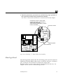
Single Inline Memory Modules (SIMMs)
SPARCstation 2 system units are equipped with a minimum of 16 megabytes of
random access memory (RAM). Physically, RAM chips are grouped together
in single inline memory modules (SIMMs). Each SIMM contains 4 megabytes
of memory and plugs into a SIMM slot located on the main logic board of the
system unit. Additional SIMMs may be added to the system unit as needed in
16-megabyte increments, up to a maximum of 16 SIMMs (64 megabytes).
Determining Faulty SIMM Locations
SunOS, Sundiag System Exerciser, SunDiagnostic Executive, and POST
diagnostics can report memory errors encountered during program execution.
Memory error messages on the system monitor display usually include a
physical memory address of the error.
Depending on the diagnostic program you are running and the SunOS release
loaded, a SIMM location number (“U” number) may be displayed. If the
location number is present in the error message, follow the instructions later in
this chapter for removing the defective SIMM at that location and installing a
replacement (see Figure 4-7 for SIMM location numbers).
If the location number is not displayed but a physical memory address is
shown, refer to the following table to locate the SIMM bank in which the
defective SIMM is installed.
46
SPARCstation 2 Field Service Manual—February 1991
4
Bank Physical Address Range
Byte
(Bits)
SIMM
0
000000-ffffff
0
1
2
3
31-24
23-16
15-8
7-0
U0311
U0309
U0307
U0322
1
1000000-1ffffff
0
1
2
3
31-24
23-16
15-8
7-0
U0312
(U0310)
U0308
U0321
2
2000000-2ffffff
0
1
2
3
31-24
23-16
15-8
7-0
U0313
(U0314)
U0315
U0320
3
3000000-3ffffff
0
1
2
3
31-24
23-16
15-8
7-0
U0319
(U318)
U0317
U0316
Bits
Bits
31.......24 23.......16
Byte 0
Byte 1
Bits
15.......8
Bits
7.......0
Byte 2
Byte 3
For example, if an error is detected at physical memory address 12fe958, the
defective SIMM is located in bank 1. If you also know the failing byte at that
address, the table shows the “U” number location of the failing SIMM. Follow
the instructions later in this chapter for removing the defective SIMM at that
location and installing a replacement (see Figure 4-7 for SIMM location
numbers).
FRU Replacement
47
4
!
Caution – SIMMs are made of delicate electronic components that are
extremely sensitive to static electricity. Ordinary amounts of static from your
clothes or work environment can destroy the modules.
Handle boards only by the edges. Do not touch components themselves or any
metal parts. Always wear a grounding strap when handling the modules.
Do not disconnect the power cord from the system unit’s power outlet or from
the wall socket. This connection provides the ground path necessary to safely
remove and install the modules.
Make sure that the system unit’s power is turned off by checking to make sure
that the green light-emitting diode (LED) at the front of the chassis is not lit
and that the fans are not running.
Note – Bank 0 must be filled with SIMMs or the system will not pass its poweron self test.
To remove a SIMM, follow these steps:
1. Read the parts of Chapter 3 about how to halt your system, tools needed,
removing expansion units, attaching a wrist strap, and removing the
system unit’s cover.
2. Check that the green LED at the front of the chassis is not lit.
3. Check that the fans are not running.
4. Check that the system’s power cord remains connected to the system and
the wall outlet.
5. Locate the SIMM slots on the main logic board. The SIMM components
must be facing toward you (see Figures 4-6 and 4-7).
Note – Slots U0310, U0314, and U0318 are not identified on the board with any
visible markings.
6. Insert the hooked end of the extraction tool (see Figure 4-3) into the left or
right SIMM extraction hole.
Use the hole that allows rotation of the tool to the left or right without
encountering obstructions (see Figure 4-4)
48
SPARCstation 2 Field Service Manual—February 1991
4
Figure 4-3
SIMM Extraction Tool
SIMM slot
(top view)
Rotate tool in
this direction only
Rotate tool in
this direction only
Figure 4-4
Inserting the SIMM Extraction Tool
7. Rotate the tool in a sideways motion, prying the side of the SIMM
upward.
8. You will hear a click when the SIMM has disengaged from the slot.
9. With the tool still in the hole, continue to lift the side of the SIMM until
the edge clears the slot.
10. Remove the tool.
11. Grasp the SIMM by the left and right edges and continue to lift straight
up until the module is free of the slot.
Take note of the slot numbers you are extracting the SIMMs from. See
Figure 4-5 for final removal of a SIMM.
FRU Replacement
49
4
Peg
Figure 4-5
SIMM slot
(top view)
Peg
Final Manual Removal of a SIMM
To install a SIMM, follow these steps:
If you have removed a SIMM because it was defective, install the replacement
SIMM into the same slot from which the defective one was removed. You must
install the SIMMs in unoccupied slots so that the slots are filled by banks.
For example, you have removed the SIMM from slot U0320 from bank 2. You
need to replace the SIMM in slot U0320 from bank 2 so that all slots in bank 2
are filled. There should be SIMMs in slot U0313, U0314, and U0315 to begin
with, so all four slots in bank 2 are filled. Table 4-1 identifies memory banks
and slots.
!
Caution – SIMMs are made of delicate electronic components that are
extremely sensitive to static electricity. Ordinary amounts of static from your
clothes or work environment can destroy the modules.
Do not remove the SIMMs from the anti-static container until told to do so.
Handle the modules only by the edges. Do not touch components themselves
or any metal parts. Always wear a grounding strap when handling the
modules.
50
SPARCstation 2 Field Service Manual—February 1991
4
1. Read the parts of Chapter 3 about how to halt your system, tools needed,
removing expansion units, attaching a wrist strap, and removing the
system unit’s cover.
2. Check that the green LED at the front of the chassis is not lit.
3. Check that the fans are not running.
4. Check that the system’s power cord remains connected to the system and
the wall outlet.
5. Locate the SIMM slots on the main logic board (see Figures 4-6 and 4-7).
Boot
PROM
Lithium
battery
Serial port
jumpers
Back panel
SPARC floating
point unit (FPU)
SPARC integer
unit (IU)
Power
supply
SBus slots
SIMM
slots
Cache
controller
Hard
drive
1
Front panel
Figure 4-6
SIMM
slots
Hard
drive
2
Diskette
drive
Fan
assembly
System
speaker
Location of SIMM Slots in System Unit
FRU Replacement
51
4
SBus slots
U0311
U0322
U0312
U0321
U0313
U0320
U0319
U0316
U0309
U0307
(U0310)
U0308
(U0314)
U0315
(U0318)
U0317
Hard drive(s)
Figure 4-7
Table 4-1
SIMM Slot Location on Main Logic Board
Table of Memory Banks
Bank:
Slots:
0
U0311
U0309
U0322
U0307
1
U0312
(U0310)
U0321
U0308
2
U0313
(U0314)
U0320
U0315
3
U0319
(U0318)
U0316
U0317
Note: Slots U0310, U0314, and U0318 are not identified on the board with any
visible markings. These slots are shown in Figure 4-7 andTable 4-1 in
parentheses.
52
SPARCstation 2 Field Service Manual—February 1991
4
6. Place an anti-static mat shiny side up, next to the system unit.
The mat comes with your SIMMs.
7. Make sure the wrist strap is securely attached to your wrist and the metal
casing of the power supply.
8. See Chapter 3 for instructions on how to attach a wrist strap.
9. Open the anti-static container and take out the SIMMs.
10. Place the SIMMs on the anti-static mat. Figure 4-8 shows typical SIMM.
Figure 4-8
4 Megabyte SIMM: Horizontally-mounted Chips
11. Holding a SIMM at its edges, insert it into the plastic guides by pushing
straight down.
The SIMM should rest loosely in the slot. The SIMMs are keyed to allow
installation in only one direction. When a SIMM is properly installed, its
component side must face the back panel.
FRU Replacement
53
4
12. Place your thumbs on opposite corners of the SIMM and press firmly
until the SIMM snaps into place.
Press down
Press down
Key
Plastic guide
Plastic guide
13. Replace the system unit’s top cover.
See “Replacing the System Unit’s Cover” near the end of this chapter.
14. Turn the system unit’s power on, and check for proper operation of the
system unit and the installed SIMMs.
See “How to Turn the Power Back On” at the end of this chapter.
SBus Boards
The system can be equipped with a variety of optional printed circuit boards.
The following are examples of the boards that plug into the SBus slots on the
system’s main logic board. This list is not necessarily inclusive.
54
•
GX Graphics Accelerator Board
This board controls the video output from the system unit, and accelerates
the generation of graphic images. The GX Graphics Accelerator board
occupies two SBus slots on the main logic board.
•
Color Frame Buffer Board
This board occupies one SBus slot. This board controls the video output
from the system unit to a color monitor.
SPARCstation 2 Field Service Manual—February 1991
4
•
Second Ethernet Board
This board provides you with an extra Ethernet port. The Ethernet board is
used in applications in which your SPARCstation 2 acts as a gateway
between two physically distinct Ethernet networks. This board has two
connectors: standard (thick) Ethernet and thin Ethernet, and occupies one
SBus slot.
•
GS Graphics Accelerator Board
This option consists of two boards that are plugged to each other on their
component sides. They are triple-wide SBus boards and occupy three SBus
slots. Figure 4-2 shows the top side of GS Graphics Accelerator Board when
it is installed in the system unit. This option provides 24-bit color and 3
dimensional graphics capabilities. It also requires a 76 Hz color monitor.
•
Video Frame Capture Board
This board occupies one SBus slot. This board takes video input and
displays it on color or monochrome monitors.
•
SBus Printer Card
This board occupies one SBus slot. This board allows the connection of the
SBus to printing, plotting and scanning devices.
•
1-Bit Analog Frame Buffer Board
This board occupies one SBus slot. It controls the video output from the
system to a monochrome monitor.
If you have removed an SBus board because it was defective, replace SBus
board into the same slot(s) from which the defective one was removed. For
information on installing the SBus board, see the manual included with it.
To remove an SBus board from the system unit:
1. Read the parts of Chapter 3 about how to halt your system, tools needed,
removing expansion units, attaching a wrist strap, and removing the
system unit’s cover.
2. Check that the green LED at the front of the chassis is not lit.
3. Check that the fans are not running.
4. Check that the system’s power cord remains connected to the system and
the wall outlet.
FRU Replacement
55
4
5. Locate the SBus board you want to remove.
6. Remove the external connectors attached to the SBus board.
Put your index fingers or thumbs underneath the corners of the SBus board
where it is plugged into the slot. Pull up on the board
!
Caution – The plastic SBus retainer is not a handle. Pulling on the SBus board
retainer can cause it to break.
This action releases the SBus board from the SBus slot
.
Pull up on corners underneath
of board. Do not pull on plastic
SBus board retainer
SBus board retainer
Holes that receive
mounting plate hooks
SBus slot 1
SBus slot 2
SBus slot 3
To replace an SBus board in the system unit:
1. Slide the SBus board at an angle into the back panel of the system unit
(see the following figure).
Make sure that the mounting plate on the SBus board hooks upward into the
Margin noteThe mounting slots
are above the rectangular opening
holes at the back panel of the system unit.
for the connector in the back
panel.
56
SPARCstation 2 Field Service Manual—February 1991
4
!
Caution – When replacing the SBus board, do not press down on the SBus
board retainer. The SBus board retainer is not a handle. Pressing down on it
may break the retainer.
Press on corners of
board. Do not press on
plastic SBus board retainer
SBus board retainer
Holes that receive
mounting plate hooks
SBus slot 1
SBus slot 2
SBus slot 3
2. Push the SBus board against the back panel.
Align the plug with the socket of the SBus slot and gently press the plug
into the socket by pressing with your fingers on the corners of the SBus
board.
!
Caution – Using excessive force may bend or damage the pins.
3. Replace the top cover of the system unit.
To do this, see “Replacing the System Unit’s Cover” near the end of this
chapter.
4. Replace the external cables to the SBus boards.
FRU Replacement
57
4
5. Turn the system unit’s power on, and check for proper operation of the
system unit and the replaced SBus board.
See “How to Turn the Power Back On” at the end of this chapter.
Power Supply
The power supply is a self-contained metal assembly located just behind the
diskette drive (see Figure 4-9). The recess in the bottom of the chassis is for the
fan that is built into the power supply.
The power supply is held in place by two guides in the bottom of the chassis,
two tabs that mate with two slots in the bottom of the power supply, and a
screw. The screw is inserted through the rear bezel of the system unit.
A 12-pin power cable connects the power supply to the main logic board just
behind the power cable connector for the diskette drive.
Warning – Make sure that the system unit is unplugged from the AC power
outlet and the power switch is in the off position before you remove, replace, or
install the power supply in the system unit. Failure to take this precaution may
result in severe electrical shock.
To remove the power supply follow these steps:
1. Read the parts of Chapter 3 about how to halt your system, tools needed,
removing expansion units, attaching a wrist strap, and removing the
system unit’s cover.
2. Check that the green LED at the front of the chassis is not lit.
3. Check that the fans are not running.
4. Remove the power cord from the system unit.
5. Remove the screw from the back panel (Figure 4-9).
6. Disconnect the cable from the white 12-pin connector (J0701) on the main
logic board.
7. Grasp the power supply.
Slide it forward toward the front of the chassis and lift it out of the chassis.
58
SPARCstation 2 Field Service Manual—February 1991
4
To replace a new power supply follow these steps:
1. Align the new power supply correctly as shown in Figure 4-9 with the
tabs and guides in the bottom of the chassis.
2. Position the power supply by pushing it firmly toward the rear of the
chassis until it locks into the tabs.
3. Connect the power cable to the white 12-pin connector (J0701) on the main
logic board.
The connector is keyed so that the power cable will fit only one way (see
Figure 4-9).
4. Secure the power supply to the chassis by installing the screw through the
rear panel of the chassis (see Figure 4-9).
5. Replace the system unit’s top cover.
See “Replacing the System Unit’s Cover” near the end of this chapter.
6. Connect the power cord to the system unit.
7. Turn the system unit’s power on, and check for proper operation of the
system unit and the newly replaced power supply.
See “How to Turn the Power Back On” towards the end of this chapter.
If the newly replaced power supply still does not work properly, a problem
exists in the system unit, such as a blown component or a short circuit.
Refer to the section “Before Replacing the main Logic Board” later in this
document for power supply voltage measurement procedures.
Note – Make sure the power supply is connected to the main logic board before
making any voltage measurements.
FRU Replacement
59
4
Power cable with
12-pin connector
Power supply
Tabs and guides
Power supply
securing screw
12-pin main logic
board power connector
Figure 4-9
Removing and Replacing the Power Supply
Hard Disk Drive
Two 3 1/2-inch half-height hard disk drives can be installed in the system
chassis. A 50-pin SCSI data cable and a 4-pin power cable connect to the rear
of each drive. Each drive and its plastic mounting bracket are secured to the
chassis by four mounting tabs and two locking tabs that fit into slots in the
bottom of the chassis.
60
SPARCstation 2 Field Service Manual—February 1991
4
!
Caution – The hard disk drive contains electronic components that are
extremely sensitive to static electricity. Ordinary amounts of static from your
clothes or work environment can destroy the components.
Do not touch the components themselves or any metal parts. Wear a
grounding strap when handling the drive. See “Attaching a Wrist Strap” in
Chapter 3.
Do not disconnect the power cord from the system unit’s power outlet or from
the wall outlet. This connection provides the ground path necessary to safely
remove and install the hard disk drive.
Make sure that the system unit’s power is turned off by checking to make sure
that the green light-emitting diode (LED) at the front of the chassis is not lit
and that the fans are not running.
To remove a hard disk drive:
1. Read the parts of Chapter 3 about how to halt your system, tools needed,
removing expansion units, attaching a wrist strap, and removing the
system unit’s cover.
2. Check that the green LED at the front of the chassis is not lit.
3. Check that the fans are not running.
4. Check that the system’s power cord remains connected to the system and
the wall outlet.
5. Disconnect the hard disk drive power and data cables from the main logic
board (see Figure 4-14).
6. Grasp the hard disk drive mounting bracket handle (see Figure 4-14). Pull
it up slightly to release the locking tabs on the bottom of the mounting
bracket.
7. Slide the hard disk drive toward the rear of the chassis. Lift the hard disk
drive out of the chassis.
This completes the hard disk drive removal process.
FRU Replacement
61
4
To prepare a hard disk drive for replacement:
Before replacing a hard disk drive, you must verify that the SCSI drive address
ID is installed correctly (see Table 4-2).
The SCSI device ID of drive 1 must be 3. The SCSI device ID of drive 2 must
be 1 (see Table 4-2). The factory setting for all replacement hard disk drives is
SCSI device ID 3.
Table 4-2
Table of Hard Disk ID Jumper Settings
Drive Number
SCSI Device ID
Jumper Setting
1
See Figure 4-15
3
See Figures 4-10
and 4-11
2
See Figure 4-15
1
See Figures 4-12
and 4-13
Depending on the replacement drive available, the jumpers are located either
near the lower right corner of the drive controller board, or near the lower left
corner.
Note – The markings for the jumpers on the drive shown in Figures 4-10 and
4-12 are etched or labeled onto the drive’s controller board. The jumpers on the
drive shown in Figures 4-11 and 4-13 are not marked on the drive’s controller
board.
1. Remove the four screws from the bracket and remove the bracket from the
drive.
Set the old drive aside on the static mat.
2. Remove the replacement drive from its protective packaging and set it
with the component side up on the antistatic mat.
You now have access to the drive controller board.
Go to the next step if you are replacing drive 1. Go to step 4 if you are
replacing drive 2.
62
SPARCstation 2 Field Service Manual—February 1991
4
3. Inspect the jumper settings. Compare them to the settings shown in
Figure 4-10 or 4-12.
° If the settings are the same as in the figure that matches your drive, leave
them as they are.
° If the settings are not the same, change them to match the settings in the
figure.
Go to step 5.
4. Inspect the jumper settings. Compare them to the settings shown in
Figure 4-11 or 4-13.
° If the settings are the same as in the figure that matches your drive, leave
them as they are.
° If the settings are not the same, change them to match the settings in the
figure.
5. Replace the mounting bracket on the new drive.
Fasten the bracket to the drive by inserting and tightening the four screws
through the bottom of the bracket into the bottom of the drive.
6. Remove the power and data cables from the old drive and connect them to
the replacement drive.
The power and data cables are keyed so they will fit only one way.
FRU Replacement
63
4
SS (self test)
EP (enable parity)
WP (enable wait spin)
Empty slot
A0
A1
SCSI device
address
A2
Figure 4-10 Hard Disk Drive with 6 Jumpers—Jumper Setting for Drive 1
A0
A1
SCSI device
address
A2
EP (enable parity)
WP (disable wait spin)
(jumpers not labeled on drive)
Figure 4-11 Hard Disk Drive with 5 Jumpers—Jumper Setting for Drive 1
64
SPARCstation 2 Field Service Manual—February 1991
4
SS (self test)
EP (enable parity)
WP (enable wait spin)
Empty slot
A0
A1
SCSI device
address
A2
Figure 4-12 Hard Disk Drive with 6 Jumpers—Jumper Setting for Drive 2
A0
A1
SCSI device
address
A2
EP (enable parity)
WP (disable wait spin)
(jumpers not labeled on drive)
Figure 4-13 Hard Disk Drive with 5 Jumpers—Jumper Setting for Drive 2
FRU Replacement
65
4
To replace a hard disk drive:
1. Make sure you have followed the previous procedure on preparing the
hard disk drive for replacement.
2. Lower the drive into the chassis and align the four mounting tabs on the
bottom of the drive mounting bracket with the slots in the bottom of the
chassis (see Figure 4-14).
The drive unit’s data and power cables should be facing the rear of the
chassis. Slide the drive forward toward the front of the chassis until the two
rear locking tabs click into their slots.
3. Connect the data and power cables to the main logic board (see Figure
4-15).
4. The data cable plugs into the data connector on the main logic board.
The data cable is keyed so that it will fit only one way.
5. The power cable plugs into the power connector on the main logic board.
The power connector is keyed so that it will fit only one way.
6. Replace the system unit’s top cover.
See “Replacing the System Unit’s Cover” near the end of this chapter.
7. Turn the system unit’s power on, and check for proper operation of the
system unit and the replaced hard disk drives.
See “How to Turn the Power Back On” towards the end of this chapter.
66
SPARCstation 2 Field Service Manual—February 1991
4
Hard disk 2
Mounting
bracket handle
Mounting tab slots
Hard disk 1
SCSI data cable and
power connections
on main logic board
Figure 4-14 Removing and Replacing the Hard Disk Drive.
FRU Replacement
67
4
Power cable
Data cable
Internal hard
disk drive
Power
supply
Diskette
drive
Front panel
System speaker
Fan assembly
Hard drive 1 power cable
(blue-black-black-red)
connects to J0703, and
ribbon cable connects
to J0402.
Hard drive 2 power cable
(blue-black-black-red)
connects to J0702 (not
completely visible) and ribbon
cable connects to J0401.
Figure 4-15 Connecting Power and Data Cables to the Hard Disk Drive
Diskette Drive
The diskette drive is located at the front right side of the chassis next to the
hard disk drives (see Figures 4-1 and 4-16). A 34-pin data cable and a 4-pin
power cable connect to the rear of the drive. The drive and its mounting
bracket are secured to the chassis by four mounting tabs and two locking tabs
that fit into slots in the bottom of the chassis.
68
SPARCstation 2 Field Service Manual—February 1991
4
!
Caution – The diskette drive contains electronic components that are extremely
sensitive to static electricity. Ordinary amounts of static from your clothes or
work environment can destroy the components.
Do not touch the components themselves or any metal parts. Wear a
grounding strap when handling the drive. See “Attaching a Wrist Strap” in
Chapter 3.
Do not disconnect the power cord from the system unit’s power outlet or from
the wall socket. This connection provides the ground path necessary to safely
remove and install the diskette drive.
Make sure that the system unit’s power is turned off by checking that the green
light-emitting diode (LED) at the front of the chassis is not lit and the fans are
not running.
To remove the diskette drive:
1. Read the parts of Chapter 3 about how to halt your system, tools needed,
removing expansion units, attaching a wrist strap, and removing the
system unit’s cover.
2. Check that the green LED at the front of the chassis is not lit.
3. Check that the fans are not running.
4. Check that the system’s power cord remains connected to the system and
the wall outlet.
5. Disconnect the diskette drive’s data cable from the main logic board.
6. Disconnect the "Y" power cable from the main logic board and the fan
assembly (see Figure 4-17).
7. Grasp the diskette drive mounting bracket handle (see Figure 4-16).
Pull it up slightly to release the locking tabs on the bottom of the mounting
bracket.
8. Slide the diskette drive toward the center of the chassis.
Lift the diskette drive out of the chassis.This completes the diskette drive
removal process.
FRU Replacement
69
4
Diskette drive
Mounting
bracket handle
Mounting
tab slots
Figure 4-16 Removing and Replacing the Diskette Drive
To prepare a diskette for replacement:
1. Remove the mounting bracket from the drive.
Turn the drive over and remove the four screws securing the bracket to the
bottom of the drive.
2. Disconnect the data and "Y" power cable from the drive (see Figure 4-17).
3. Remove the replacement drive from its protective packaging.
4. Install the mounting bracket on the replacement drive.
Fasten the bracket to the bottom of the hard drive by inserting and
tightening the four screws through the bracket.
70
SPARCstation 2 Field Service Manual—February 1991
4
5. Connect the data and "Y" power cables to the replacement drive (see
Figure 4-17).
The power and data connector are keyed so they will fit only one way.
To replace the diskette drive:
1. Align the four mounting tabs on the bottom of the drive mounting
bracket with the slots in the bottom of the chassis (see Figure 4-16).
2. Slide the drive forward towards the outside of the chassis until the two
locking tabs click into their slots.
3. Connect the data and "Y" power cables to the main logic board (see
Figure 4-17).
4. The data and power connectors plug into the data and power connectors
on the main logic board.
The connectors are keyed so that each will fit only one way.
5. Connect the "Y" power cable to the fan assembly (see Figure 4-17).
6. Replace the system unit’s top cover.
See “Replacing the System Unit’s Cover” near the end of in this chapter.
7. Turn the system unit’s power on, and check for proper operation of the
system unit and the replaced diskette drive.
See “How to Turn the Power Back On” at the end of this chapter.
FRU Replacement
71
4
Connector P1 of the "Y" power cable
(yellow, black, black, red) connects to
J0704 (main logic board).
Connector P2 (black, red) connects
to diskette drive.
Data cable
connects
to J0501
Internal
diskette
drive
Power
supply
SIMM
slots
System speaker
Fan assembly
Internal hard
disk drives
Diskette
drive
Front panel
Figure 4-17 Connecting Power and Data Cables to the Diskette Drive
Fan Assembly
Each SPARCstation 2 contains two fan assemblies. One of them is built into
the power supply. Although the power supply is a field replaceable-unit, the
fan assembly resides in the power supply itself is not a field replaceable-unit.
See “Power Supply” earlier in this Chapter. The other fan assembly is located
at the front right side of the chassis, next to the diskette drive and the system
speaker (see Figure 4-18). This fan assembly is a field replaceable unit.
72
SPARCstation 2 Field Service Manual—February 1991
4
To remove the fan assembly:
1. Read the parts of Chapter 3 about how to halt your system, tools needed,
removing expansion units, attaching a wrist strap, and removing the
system unit’s cover.
2. Check that the green LED at the front of the chassis is not lit.
3. Check that the fans are not running.
4. Check that the system’s power cord remains connected to the system and
the wall outlet.
5. Disconnect the fan cable from the 2-pin connector of "Y" power cable
(Figure 4-19).
6. Remove both screws from the fan assembly (Figure 4-18).
7. Remove the fingerguard (Figure 4-18).
8. Grasp and lift the fan assembly out of the chassis.
FRU Replacement
73
4
Securing screws
Fingerguard
Fan assembly
Hard disk 1
Figure 4-18 Removing and Replacing the Fan Assembly
To replace the fan assembly:
1. Align the replacement fan assembly such that the mounting holes on the
fan and the chassis are lined up.
The locator on the chassis makes sure that the fan is oriented the correct
way (Figure 4-18).
2. Connect the fan cable to the 2-pin connector of "Y" power cable
(Figure 4-19).
3. Place the fingerguard on top of the fan assembly.
4. Install both screws through the fingerguard, fan assembly and the chassis
(Figure 4-18).
5. Replace the system units’s top cover.
See “Replacing the System Unit’s Cover” near the end of this chapter.
74
SPARCstation 2 Field Service Manual—February 1991
4
6. Turn the system unit’s power back on, and check for proper operation of
the system unit and the newly installed fan assembly.
See “How to Turn the Power Back On” towards the end of this chapter.
Connector P1 of the "Y" power cable
(yellow, black, black, red) connects to
J0704 (main logic board).
2-pin connector (yellow, black) connects
to the fan assembly.
Connects to J0704
Internal
diskette
drive
Power
supply
SIMM
slots
System speaker
Fan assembly
Internal hard
disk drives
Diskette
drive
Front panel
Figure 4-19 Connecting "Y" Power Cable to Fan Assembly.
Main Logic Board
The main logic board contains the CPU, the floating point coprocessor, the boot
PROM, the NVRAM, SIMMs, SBus boards, two RS-423/232 ports, an Ethernet
port, a SCSI port, and connectors for audio input/output, and
keyboard/mouse as well as many other ICs (see Figures 4-20 and 4-21). See
Chapter 1 for an overview of the main logic board.
FRU Replacement
75
4
In addition, a 12-pin plug connects to the power supply cable to provide power
to the board and the disk drives. The 34-line diskette drive data and power
cables connect to the main logic board just in front of the white 12-pin
connector plug. The 50-line SCSI data cables and the hard disk drive power
cables connect along the front of the main logic board to the left of the speaker
and diskette data cable connections.
Serial Port Jumpers
There are two serial port jumpers on the main logic board (see Figures 4-20 and
4-21). The jumpers are preset from the factory in RS-423 mode. The ports can
be set either as RS-232 mode (for users in the Federal Republic of Germany) or
as RS-423 mode for the rest of the users. See SPARCstation 2 Installation Guide
for more information on serial port mode jumpers.
To change the serial port jumpers on the main logic board to RS-232 mode:
1. Read the parts of Chapter 3 about how to halt your system, tools needed,
removing expansion units, removing the system unit’s cover and attaching
a wrist strap.
2. Check that the green LED at the front of the chassis is not lit.
3. Check that the fans are not running.
4. Check that the system’s power cord remains connected to the system and
the wall outlet.
5. Locate the jumper blocks on the main logic board near the lithium battery.
See Figures 4-20, 4-21, 4-22 and 4-23.
76
SPARCstation 2 Field Service Manual—February 1991
4
Boot
PROM
Lithium
battery
Serial port
jumpers
Back panel
SPARC floating
point unit (FPU)
SPARC integer
unit (IU)
Power
supply
SBus slots
Cache
controller
SIMM
slots
Hard
drive
1
Front panel
SIMM
slots
Hard
drive
2
Diskette
drive
Fan
System
assembly speaker
Figure 4-20 Top View of System Unit’s Internal Parts
FRU Replacement
77
4
RS232
J0404
Ethernet port
RS423
Lithium
battery
Back panel
J0502
serial port A
Boot PROM
Figure 4-21 Serial Port Jumpers
RS232
RS423
Figure 4-22 Preset RS-423 Jumper Positions
6. Use a pair of needlenose pliers and move both jumpers from the RS-423
positions to the RS-232 positions.
78
SPARCstation 2 Field Service Manual—February 1991
4
RS232
RS423
Figure 4-23 RS-232 Jumper Positions
7. Replace the top cover of the system unit.
To do this, see “Replacing the System Unit’s Cover” near the end of this
chapter.
8. Turn the power of the system unit on, and check for proper operation of
the system unit.
See “How to turn the Power Back On” towards the end of this chapter.
Main Logic Board Voltage Test Points
There are no voltage test points on the main logic board. If you need to
measure DC voltages, use the pins on the 12-pin power supply connector
(J0701) located on the main logic board (Figure 4-25). The pins with red wires
are +5 V, the blue wires are +12 V, the brown wire is -12 V, and the black wires
are GROUND. See Figure 4-24 for pin locations if the wire colors described
here do not match the connector.
The acceptable range for +5 V voltage is +4.90 V to +5.10 V. The acceptable
range for +12 V is +11.6 V to +12.84 V. The allowable range for -12 V is -11.6 V
to -13.2 V with an internal disk drive installed, or -10.2 V to -13.8 V without an
internal drive.
FRU Replacement
79
4
+5V
7
1
+5V
+5V
8
2
+5V
GND
9
3
GND
GND
10
4
GND
+12V
11
5
+12V
-12V
12
6
Power On Reset
Figure 4-24 Pin Location of Power Supply Connector (J0701)
80
SPARCstation 2 Field Service Manual—February 1991
4
Back Panel
J0503 TTY B
J0502 TTY A
J0601 KBD
J0504
4
SPARC
FPU
5
1
J0404
6
7
J0403 SCSI
E-NET
8
E-NET
OSC
SPARC
IU
2
CACHE
Ctlr
3
MMU+
MMU+
SBus Slot 2
DMA
Ctlr
MMU+
MMU+
SBus Slot 3
SCSI
Ctlr
MMU+
J0705
MMU+
MMU+
SBus Slot 1
J0704
S4
RAM
J0701
SIMM
Slots
J0703
SIMM
Slots
J0402 HD1 SCSI
J0702
J0401 HD2 SCSI
J0602
J0501
Front Panel
Figure 4-25 Main Logic Board Layout
FRU Replacement
81
4
Table 4-3
82
Main Logic Board Parts layout: Legend
Figure 4-25
Definition
1
2
3
4
5
6
7
8
DMA CTRL
E-NET
MMU+
OSC
RAM CTRL
SCSI Ctrl
SIMM
J0401
J0402
J0403
J0404
J0501
J0502
J0503
J0504
J0601
J0602
J0701
J0702
J0703
J0704
J0705
SPARC Floating Point Unit
SPARC Integer Unit
Cache Controller
Cache Data RAM (chip set)
Cache Data RAM (chip set)
Boot PROM
NVRAM, Time-of-Day Clock, Lithium Battery
RS-232 and RS-423 serial port mode jumpers
DMA Controller, S4 DMA+
Ethernet Controller (chip set)
Memory Management Unit+ (chip set)
Oscillator
RAM Controller, S4 RAM
SCSI Controller
Single Inline Memory Module
Hard Drive 2 SCSI cable connector
Hard Drive 1 SCSI cable connector
SCSI port
Ehternet port
Diskette Drive data cable connector
Serial Port A
Serial Port B
Keyboard cable connector
Audio Input/Output cable connector
System Speaker and LED connector
Power Supply connector
Hard Drive 2 power connector
Hard Drive 1 power connector
Diskette drive power connector
Memory/SBus expansion connector
SPARCstation 2 Field Service Manual—February 1991
4
Table 4-4
!
List of Acronyms
Acronyms
Full Expression
DMA
MMU+
NVRAM
PROM
RAM
SCSI
SIMM
Direct Memory Access
Memory Management Unit+
Non-Volatile Random Access Memory
Programmable Read-Only Memory
Random Access Memory
Small Computer System Interface
Single Inline Memory Module
Caution – Printed circuit boards are made of delicate electronic components
that are extremely sensitive to static electricity. Ordinary amounts of static
from your clothes or work environment can destroy the boards.
Handle boards only by the non-conducting edges. Do not touch components
themselves or any metal parts. Always wear a grounding strap when handling
the boards.
Do not disconnect the power cord from the system unit’s power outlet. This
connection provides the ground path necessary to safely remove and install the
boards.
Make sure that the system unit’s power is turned off by checking to make sure
that the green light-emitting diode (LED) at the front of the chassis is not lit
and that the fans are not running.
Before Replacing the Main Logic Board
This section explains with steps to perform before removing and replacing the
main logic board. Removing and replacing the main logic board is a drastic
step to take. Therefore, it is important to try to troubleshoot all other
possibilities before removing and replacing the main logic board.
FRU Replacement
83
4
To check for and eliminate other possible problems before you replace the main
logic board:
1. Read the parts of Chapter 3 about how to halt your system, tools needed,
removing expansion units, removing the system unit’s cover and attaching
a wrist strap.
2. Check that the green LED at the front of the chassis is not lit.
3. Check that the fans are not running.
4. Check that the system’s power cord remains connected to the system and
the wall outlet.
5. Connect a terminal to the system unit.
For details, see the SPARCstation 2 Installation Guide.
6. This enables you to view output of the POST test results as they are run.
7. Disconnect the graphics monitor and the Ethernet connectors.
8. Remove the SBus boards from the system.
To do this see “SBus Boards” earlier in this chapter.
9. Unplug the hard disk drives and the diskette drive from their data and
power cables.
See Figures 4-17 and 4-19 in this chapter for the location of the data and
power cables.
10. Make sure all SIMMs are correctly seated (see Figures 4-6 and 4-7 for the
location of the SIMM slots), all cables attached, and all chips on the main
logic board correctly seated in their sockets.
Note – Bank 0 must be filled with SIMMs or the system will not pass its poweron self test.
11. Turn the system power on.
12. Measure the power supply voltages with a VOM (Figure 4-26).
!
84
Caution – Measuring voltages without connecting the DC cable to the main logic
board will result in inaccurate readings. Without load, the power supply will
not regulate.
SPARCstation 2 Field Service Manual—February 1991
4
The wire colors are the following:
Red
Blue
Brown
Gray
Black
+5 V
+12 V
-12 V
Por (Power On Reset from the power supply)
Ground
Note – The Por Signal is a TTL open collector and pull up is on the main logic
board.
The limits for the voltages are:
+5 V
+12 V
-12 V
-12 V
4.90 V to 5.10 V
11.16 V to 12.84 V
-11.16 V to -13.20 V with an internal drive
-10.20 V to -13.80 V without an internal drive
Do the following in sequence:
° Turn the power off and connect the hard disk drive and diskette drive
power and data cables.
° Turn the power on and again measure the power supply voltages. If the
voltages are correct, you have ruled out that the power supply is
defective. Go to step 12. If any of the voltages are incorrect, follow the
next step.
° Disconnect each drive separately until the correct voltages are measured.
Replace the drive that is holding the voltage down.
° With the power off, install the SBus boards that were removed earlier.
Turn on the power and measure the power supply voltages.
° If any voltages are incorrect after installing the SBus boards, remove the
boards until the voltages are correct and replace the bad board. If the
voltages are correct, you have ruled out that the power supply is
defective.
13. Replace the system unit’s cover.
To do this see “Replacing the System Unit’s Cover” towards the end of this
chapter.
FRU Replacement
85
4
14. Turn on the system and the terminal.
The system will start to boot. To interrupt the boot sequence, press L1-A on
the system keyboard.
The default prompt is the > prompt. You can reset the default prompt to
be the ok prompt. To make the default prompt the ok prompt, see the
Open Boot PROM 2.0 Toolkit User’s Guide.
If you see the ok prompt, go to step 15. If you see the > prompt, go to
the next step.
15. At the > prompt, enter n.
16. This enters the Forth Toolkit and displays its ok prompt.
17. Use the commands shown below to set the diagnostic switch to true, set
the autoboot switch to false, and reset the system.
ok setenv diag-switch? true
ok setenv auto-boot? false
ok reset
the system is rebooted and POST is run
As POST tests run, view the results on the keyboard LEDs located on the
upper right corner of your keyboard. Figure 2-4 shows the meaning of the
LED display pattern.
18. If all POST tests pass, go to the next step.
If one or more of the following POST tests fails, take one of the following
actions:
°
°
°
86
If the PROM fails, replace the boot PROM. See “Boot PROM” later in this
chapter.
If you replace the Boot PROM and re-run the POST and the PROM test
fails again, a component between the CPU and the boot PROM on the
main logic board is defective. Reinstall the original boot PROM. See “Boot
PROM” later in this chapter. Remove and replace the main logic board.
See “Removing the Main Logic Board” and “Replacing the Main Logic
Board” later in this chapter.
If a SIMM fails, the slot number of the failing SIMM may be indicated by
keyboard LED display, but only if the SIMM belongs to bank 0 (see
Figure 2-4). The other twelve SIMM Slots will be tested by the POST
memory diagnostics and errors will be reported. Memory error messages
on the system monitor display usually include a physical memory address
SPARCstation 2 Field Service Manual—February 1991
4
°
°
°
of any failing SIMM. Depending on the diagnostic program you are
running and the SunOS release loaded, a SIMM slot number may be
displayed. See “Determining Faulty SIMM Locations” earlier this chapter.
Replace the defective SIMM. See “Single Inline Memory Modules
(SIMMs)” earlier in this chapter.
If NVRAM (or TOD or Battery) fails, replace the NVRAM. See
“NVRAM/TOD” later in this chapter.
If the main logic board fails, replace the main logic board. See “Removing
the Main Logic Board” and “Replacing the Main Logic Board” later in this
chapter.
If you see nothing on the display, and the system appears dead, replace
the main logic board. See “Removing the Main Logic Board” and
“Replacing the Main Logic Board” later in this chapter.
19. At the > or ok prompt, turn off the system’s power switch.
20. Reconnect the power and data cables to the hard disk drives and the
diskette drive.
See Figures 4-17 and 4-19 in this chapter for the location of the data and
power cables.
21. Replace the system unit’s cover.
See “Replacing the System Unit’s Cover” towards the end of this chapter.
22. If you have identified the problem, go to step 22.
If you have not identified the problem, go to next step.
23. Turn the system and the terminal on and run the Diagnostic Executive
with the cache disabled only if all POST tests passed.
If any of the Diagnostic Executive tests fail, replace the part indicated by the
test. The Diagnostic Executive is an independent operating system. It runs
exhaustive subsystem tests independent of the SunOS Operating System.
See the SunDiagnostic Executive User’s Guide for SPARC Desktop Systems.
24. At the > or ok prompts, turn off the system’s power switch.
25. Disconnect the terminal and reconnect the graphics monitor and the
Ethernet connector.
To reconnect the graphics monitor see “Installing Your Monitor” in
Appendix C of the SPARCstation 2 Installation Guide.
This completes the procedure.
FRU Replacement
87
4
Removing the Main Logic Board
This section explains how to remove the main logic board from the system
unit.
To remove the main logic board:
1. Removing and replacing the main logic board is a drastic step to take.
See “Before Replacing the Main Logic Board” for troubleshooting
information.
2. Read the parts of Chapter 3 about how to halt your system, tools needed,
removing expansion units, removing the system unit’s cover and attaching
a wrist strap.
3. Check that the green LED at the front of the chassis is not lit.
4. Check that the fans are not running.
5. Check that the system’s power cord remains connected to the system and
the wall outlet.
6. Disconnect all of the cables from the connectors on the rear of the system
unit.
7. Place an anti-static mat shiny side up next to the system unit.
8. Remove the SBus boards.
See “SBus Boards” earlier in this chapter. Place the SBus boards on the antistatic mat.
9. Remove the SIMMs from their sockets.
Note the slots they were originally installed into. Place the SIMMs on the
antistatic mat.
10. Disconnect the 12-pin power supply cable from the (J0701) connector in
the right front corner of the main logic board (see Figures 4-25 and 4-26).
11. Disconnect the LED/speaker assembly cable (J0602) from the connector in
the right front corner of the main logic board (see Figures 4-25 and 4-26).
12. Disconnect the 34-line diskette data (J0501) and power cables (J0704) from
the connectors on the main logic board (see Figures 4-27 and 4-26) and
fold them out of the way.
88
SPARCstation 2 Field Service Manual—February 1991
4
13. Disconnect the hard disk drive data (J0401 and J0402) and power cables
(J0702 and J0703) from the data and power connectors on the main logic
board (see Figures 4-25 and 4-26).
Fold them out of the way.
14. With an IC extractor or a small flat-bladed screwdriver, remove the
NVRAM chip (see Figure 4-25 and Table 4-3 for the location of the
NVRAM chip) from its socket slowly and evenly.
15. Store the NVRAM chip in conductive foam or place it on the antistatic
mat to prevent damage from electrostatic discharge.
Save the NVRAM chip for re-use.
16. Remove the two Phillips head screws that secure the board to the back
panel (see Figure 4-26).
17. Slide the main logic board toward the front of the chassis to release it
from the five standoffs in the bottom of the chassis.
18. Grasp the board by the SBus slot connectors with both hands and
carefully lift it out of the chassis.
Avoid handling any of the delicate electronic components or touching any of
the main logic board’s traces.
19. Place the main logic board on the anti-static mat.
Preparing Main Logic Board for Replacement
This section explains how to prepare the main logic board for replacement.
To prepare a main logic board for replacement:
1. Remove the NVRAM chip from the replacement main logic board and
place it on the anti-static mat.
2. Insert the NVRAM from the defective board in the replacement board at
the same location.
Match the pin 1 indicator on the NVRAM chip with the indicator on the
socket. Holding the NVRAM chip at the edges, carefully align the pins and
insert the NVRAM chip in the socket. Figure 4-25 and Table 4-3 show the
location of the NVRAM chip on the main logic board.
FRU Replacement
89
4
Replacing the Main Logic Board
This section explains how to replace the main logic board into the system unit.
To replace the main logic board:
1. Insert the connectors on the rear of the replacement board into the back
panel as shown in Figure 4-26.
2. Align the board so that the five tapered mounting holes align with the
standoffs in the bottom of the chassis.
After the board is properly aligned, slide it back toward the rear bezel until
the standoffs lock into the mounting holes.
3. Install two Phillips head screws to secure the main logic board to the rear
of the chassis (see Figure 4-26).
4. Connect the 12-pin power cable from the power supply to connector J0701
(see Figures 4-25 and 4-26) in the right front corner of the main logic
board.
5. The connector is keyed so that the power cable will fit only one way.
6. Connect the 34-line diskette drive data and power cables to the connectors
on the main logic board (see Figure 4-26).
The data cable connector is J0501 and the power connector is J0704 (see
Figure 26).
7. The connectors are keyed so they will fit only one way.
8. Connect the hard disk drive data and power cables to the data and power
connectors on the main logic board (see Figures 4-25 and 4-26).
Drive 1 data cable is J0402, and drive 1 power cable is J0703. Drive 2 data
cable is J0401, and drive 2 power cable is J0702
9. The connectors are keyed so that they will only fit one way.
10. Connect the LED/Speaker cable assembly to connector J0602 in the right
front corner of the main logic board (see Figures 4-25 and 4-26).
11. Re-install the SIMMs into their original sockets.
See “SIMMs” earlier in this chapter for the correct locations.
90
SPARCstation 2 Field Service Manual—February 1991
4
Note – Bank 0 must be filled with SIMMs or the system will not pass its poweron self test.
12. Re-install the SBus boards as directed in “SBus Boards” earlier in this
chapter.
13. Connect all of the cables to the ports at the rear of the system unit.
14. Replace the system unit’s top cover.
See “Replacing the System Unit’s Cover” later in this chapter.
15. Turn the system unit’s power on, and check for proper system operation.
See “How to Turn the Power Back On” at the end of this chapter.
FRU Replacement
91
4
From LED/
speaker assembly
540-2072
Diskette drive
data cable
530-1452
12-pin cable from
power supply
300-1038
Hard drive 2
data cable
530-1451
Hard drive 2
power cable
530-1453
P2
Diskette drive/fan
power cable
530-1679
Hard drive 1
data cable
530-1451
Hard drive 1
power cable
530-1453
Main logic board
Front panel of
system unit
Securing
screw
Back panel of
system unit
Securing
screw
Figure 4-26 Removing and Replacing the Main Logic Board
92
SPARCstation 2 Field Service Manual—February 1991
4
Boot PROM
This section explains how to remove and replace the boot PROM on the main
logic board.
To remove and replace the boot PROM, follow these steps:
1. Before removing and replacing the boot PROM, you should have verified
that the boot PROM needs to be replaced.
See “Before Replacing the Main Logic Board” earlier in this chapter before
continuing. The procedure described in that section explains how to run
POST and the Diagnostic Executive.
2. Read the parts of Chapter 3 about how to halt your system, tools needed,
removing expansion units, removing the system unit’s cover and attaching
a wrist strap.
3. Check that the green LED at the front of the chassis is not lit.
4. Check that the fans are not running.
5. Check that the system’s power cord remains connected to the system and
the wall outlet.
6. Remove the SBus boards from SBus slots 1 and 2.
See “SBus Boards” earlier in this chapter.
7. Locate the boot PROM (see Figures 4-25 and 4-26). Remove the boot
PROM.
To do this use an IC extractor or a small flat-bladed screwdriver and remove
the PROM from its socket slowly and evenly.
8. Insert the new boot PROM in the socket.
To do this, match the pin 1 indicator on the boot PROM with the indicator
on the socket. Holding the boot PROM at the edges, carefully align the pins
and insert the boot PROM in the socket. Note that inserting the chip
backwards will damage the chip.
9. Replace the SBus boards in the system unit.
See “SBus Boards” earlier in this chapter.
10. Replace the system unit’s cover.
To do this, see “Replacing the System Unit’s Cover” towards the end of this
chapter.
FRU Replacement
93
4
11. Re-run the POST test again to determine if the new boot PROM solved
the problem.
See “Before Replacing the Main Logic Board” earlier in this chapter.
NVRAM/TOD
There is a lithium battery within the NVRAM/TOD (Time of Day) chip. The
NVRAM chip is located to the right of the boot PROM (see Figures 4-25 and
4-28). You must remove the NVRAM chip from the main logic board you are
replacing and install it in the new main logic board. For more information see
“Replacing the Main Logic Board”.
To remove and replace the NVRAM/TOD chip, follow these steps:
1. Before removing and replacing the NVRAM/TOD chip, you should have
verified that the NVRAM/TOD chip needs to be replaced.
See “Before Replacing the Main Logic Board” earlier in this chapter before
continuing. The procedure described in that section explains how to run
POST and the Diagnostic Executive.
2. Read the parts of Chapter 3 about how to halt your system, tools needed,
removing expansion units, removing the system unit’s cover and attaching
a wrist strap.
3. Check that the green LED at the front of the chassis is not lit.
4. Check that the fans are not running.
5. Check that the system’s power cord remains connected to the system and
the wall outlet.
6. Remove the SBus boards from SBus slots 1 and 2. See “Removing SBus
Boards” in this chapter.
7. Locate the NVRAM/TOD chip (see Figures 4-25 and 4-26). Remove the
NVRAM/TOD chip.
To do this use an IC extractor or a small flat-bladed screwdriver and remove
the NVRAM/TOD chip from its socket slowly and evenly.
94
SPARCstation 2 Field Service Manual—February 1991
4
8. Insert the new NVRAM/TOD chip in the socket.
To do this, match the pin 1 indicator on the NVRAM/TOD chip with the
indicator on the socket. Holding the NVRAM/TOD chip at the edges,
carefully align the pins and insert the NVRAM/TOD chip in the socket.
Note that inserting the chip backwards will damage the chip.
9. Replace the system unit’s cover.
To do this, see “Replacing the System Unit’s Cover” towards the end of this
chapter.
Re-run the POST test again to determine if the new NVRAM/TOD chip solved
the problem. See “Before Replacing the Main Logic Board” earlier in this
chapter.
Warning – There is a lithium battery molded into the Mostek real-time clock,
No. MK48T02BU or No. MK48T02B-XX, where X may be any number from 1-9.
It is located on the main logic board of the system unit next to the boot PROM.
The battery may explode if mistreated. Do not disassemble it or attempt to
recharge it.
Speaker
The speaker is mounted at the front of the system on the right hand side (see
Figure 4-1). There are two parts to the speaker: the LED/speaker assembly and
the speaker clip. See Appendix B “Illustrated Parts Breakdown” for an
illustration of the speaker parts.
To test if the speaker assembly needs to be replaced:
1. Read the parts of Chapter 3 about how to halt your system, tools needed,
removing expansion units, removing the system unit’s cover and attaching
a wrist strap.
2. Turn the power on.
Connect the power cord to the system and the wall outlet. The power is
required to measure the voltage on the LED pin later on.
3. Check that the green LED at the front of the chassis is lit.
4. Check that the fans are running.
5. Locate the speaker assembly (see Figure 4-1).
FRU Replacement
95
4
6. Measure the voltage on the LED pin of the speaker connector by using a
VOM
If the voltage measured is 0 V, the LED will not light. Replace the main
logic board. See “Removing the Main Logic Board” and “Replacing the
Main Logic Board” earlier in this chapter. If at least +5 V is measured on the
LED pin of the connector and the LED does not light, the LED is bad.
Replace the LED/speaker assembly as directed in the following procedures.
7. Test if sound is heard when sound is being sent to the speaker. Replace
the system unit’s cover.
To do this see “Replacing the System Unit’s Cover” later in this chapter.
8. Bring up the system and boot the SunOS Operating System.
To do this, see “Booting Your System” in Chapter 1 of the Sun System &
Network Manager’s Guide.
9. Generate sound through the speaker by entering either of the following:
% cat /usr/demo/sound/sample.au > /dev/audioThe system plays back a spoken message
or
% cat /vmunix > /dev/audioThe system plays back garbage, which is louder
Press Control-C to abort the message
10. Replace the speaker assembly as directed in the following procedures, if
either of the sound tests fail.
If either of the sound tests pass, do not replace the speaker. Replace the
LED/speaker assembly or the main logic board only if the LED does not
light (see step 3).
96
SPARCstation 2 Field Service Manual—February 1991
4
To remove the speaker, follow these steps:
1. Read the parts of Chapter 3 about how to halt your system, tools needed,
removing expansion units, attaching a wrist strap, and removing the
system unit’s cover.
2. Check that the green LED at the front of the chassis is not lit.
3. Check that the fans are not running.
4. Check that the system’s power cord remains connected to the system and
the wall outlet.
5. Locate the speaker assembly and its 4-pin connector (J0602) at the front
right corner of the main logic board (see Figure 4-25).
6. Unplug the 4-pin connector from the main logic board.
7. Push the spring-loaded clip on the speaker clip.
Slide it forward and lift out the speaker assembly and the attached speaker
clip.
8. Pull the LED out of its mounting clip.
9. To replace the speaker, follow these steps:
10. Push the replacement LED into the mounting clip.
11. Slide the speaker assembly and the attached speaker clip into its catch
and push it down.
12. Plug the 4-pin connector onto the J0602 connector on the main logic board.
The connector is keyed so it will fit only one way.
13. Replace the system unit’s top cover.
See “Replacing the System Unit’s Cover” later in this chapter.
14. Turn the system unit’s power on, and check for proper operation of the
system unit and the replaced speaker.
See “How to Turn the Power Back On” towards the end of this chapter.
FRU Replacement
97
4
Replacing the System Unit’s Cover
To replace the system unit’s cover:
1. Hold the cover at an angle of approximately 30 degrees in relation to the
system unit chassis with the front end down and the back end up.
2. Gently guide the plastic tabs on the front of the cover into the tab slots on
the front of the chassis (see Figure 4-27).
Continue to hold the cover with your hands.
!
Caution – Holding the cover at angles greater than 30 degrees can prevent
insertion of the tabs into the tab slots. Once the tabs are in the slots, raising the
cover to angles greater than 30 degrees can break the tabs.
3. Slowly lower the cover onto the chassis, and be sure the security loop
clears the diskette drive (if equipped) and seats into the security loop slot
on the bottom of the chassis.
4. Insert the two screws that hold the top cover to the back panel.
5. Tighten the two screws with a screwdriver
98
SPARCstation 2 Field Service Manual—February 1991
4
Security loop
Plastic tabs
Insert and tighten screws in back panel.
Figure 4-27 Replacing the System Unit’s Cover
Connecting the Desktop Storage Pack
To connect the Desktop Storage Pack (DSP) to the system unit:
1. Connect the connector on the SCSI cable to the SCSI port on the system
unit’s back panel.
2. See the “Desktop Storage Pack Installation Guide” for additional
installation information.
Connecting the External Storage Module
To connect the External Storage Module (ESM) to the system unit, follow these
steps:
1. Connect the SCSI connector on the SCSI adapter cable to the SCSI port on
the system unit’s back panel.
2. See the “Sun External Storage Module” for additional installation
instructions.
FRU Replacement
99
4
Video Monitors
There are several different types of monitors and cabling. The color and
grayscale monitors use cables with 13W3 connectors. See Appendix C of the
SPARCstation 2 Installation Guide for more specific information on monitors and
monitor cables.
Mouse
The optical mouse connects to one of two jacks in the back of the keyboard.
The mouse can be connected on either the left or right side to accommodate
either left-handed or right-handed users. Connect the mouse to the keyboard
before you connect the keyboard to the system unit.
Keyboard
A cable connects the keyboard to the system unit. The keyboard port is located
at the left rear of the system unit (when viewed from the front). Connect the
keyboard cable on either the left or right side of the keyboard, then to the port
on the back of the system unit.
How to Turn the Power Back On
After turning off the power to replace FRUs, turning the power on again is
relatively simple.
Warning – This device is equipped with a 3-wire grounded power cord. To
reduce the risk of electrical shock, always plug the power cord into a properly
grounded power outlet.
!
100
Caution – Always allow 10 seconds between turning off the power and turning
it back on again. This pause prevents possible damage to power supply
components in your system unit.
SPARCstation 2 Field Service Manual—February 1991
4
Turn the power switches on in this order:
•
•
•
Monitor
External drive (if you have one)
System Unit
After a minute or so, you should see the login prompt.
system
system
system
system
system
system
system
system
system
messages
messages
messages
messages
messages
messages
messages
messages
messages
hostname login:
When you see the login screen, you can log in to your system. For more
information on logging in, see Chapter 2 of the Sun System User’s Guide.
FRU Replacement
101
4
102
SPARCstation 2 Field Service Manual—February 1991
SystemSpecifications
A
This appendix contains system specifications, including dimensions, electrical
and power requirements, environmental requirements, and compliance with
electrical and safety regulations.
Regulatory Compliance
Table A-1 lists regulatory compliance information.
Table A-1 Regulatory Compliance Information
PRODUCT SAFETY
UL 478
CSA C22.2 No. 154
IEC 380
EMI
FCC Class B
VDE Class B
DOC Class B
ERGONOMICS
German Federal Republic ZH 1/618
X-RAY EMISSIONS
DHHS, PTB
103
A
Input Power Requirements
Table A-2 lists the input power requirements for the system unit. The
maximum power dissipated is less than or equal to 120 watts. The power
supply automatically selects the correct AC voltage range.
Table A-2 Input Power Requirements and Power Dissipation for the System Unit
Operating
Voltage
Range
Maximum
Input
Current
Maximum
Input
Power
Maximum
Input
Volt-Amps
Thermal
Dissipation
Operating
Frequency
Range
87.5-132 Vac
180-264 Vac
2.1 Amps
1.2 Amps
119 Watts
119 Watts
179
179
406 BTU
406 BTU
47-63 Hz
47-63 Hz
Environmental Requirements
Table A-3 lists the environmental requirements for the operating environment
and the non-operating environment.
Table A-3 Table of Environmental Requirements
Operating Environment:
Temperature
Humidity
Wet Bulb
Altitude
Vibration
Shock
between 0 to 40 degrees C (32 and 104
degrees F)
5 to 80% relative noncondensing at 40 degrees
C (104 degrees F)
25 degrees C (77 degrees F) maximum
0 to 3,048 m (0 to 10,000 ft)
5-22 Hz, 0.01 inches p-p; 22-500 Hz, 0.25 g p-p
5 g pk, 10 msec 1/2 sine wave
Non-Operating Environment:
Temperature
Humidity
Wet Bulb
Altitude
Vibration
Shock
104
between -20 to 75 degrees C (-4 to 167grees F)
5 to 90% relative noncondensing at
40 degrees C (104 degrees F)
46 degrees C (115 degrees F) maximum
0 to 12,192 m (0 to 40,000 ft)
5-22 Hz, 0.02 inches p-p; 22-500 Hz, 0.5 g p-p
20 g pk, 30 msec
SPARCstation Field Service Manual—February 1991
A
Physical Specifications
Table A-4 lists the physical specifications for the system unit, the keyboard, the
optical mouse, and selected monitors.
Table A-4 Table of Physical Specifications
Component
Height
Width
Depth
Net Weight
System Unit
2.8 in (7.1 cm)
16 in (40.9 cm)
16 in (40.9 cm)
25 lbs (11 kg)
Keyboard
2 in (5 cm)
19 in (48 cm)
8 in (20 cm)
2 lbs (1 kg)
Mouse
2 in (5 cm)
4 in (10 cm)
3 in (8 cm)
0.3 lbs (0.14 kg)
Monitor, 16 in color
15.8 in (40 cm)
15.5 in (39.4 cm)
17.3 in (43.8 cm)
70 lbs (31.8 kg)
Monitor, 17 in grays 14.5 in (36.7 cm)
16.1 in (40.9 cm)
15.6in (339.5 cm)
37 lbs (16.8 kg)
Monitor, 19 in color
17.4 in (44.2 cm)
18.4 in (46.7 cm)
20.6 in (52.3 cm)
75 lbs (34.1 kg)
Monitor, 19 in grays 17.5 in (44.5 cm)
18.1 in (46.0 cm)
15.9 in (45.2 cm)
52 lbs (23.6 kg)
System Specifications
105
A
106
SPARCstation Field Service Manual—February 1991
IllustratedPartsBreakdown
B
This appendix illustrates how to connect the system’s component parts and
presents global views of the system.
Parts Breakdown
Figure B-1 illustrates system interconnection. Table B-1 gives part numbers of
the system components. Figure B-2 shows exploded view of the system unit.
Figure B-3 illustrates exploded view of the system unit showing drive brackets.
Figure B-4 shows exploded view of main logic board in the system unit.
107
B
Monitor
Keyboard cable
O I
SCSI
terminator
External drive
(optional)
Keyboard
Mouse
and cable
Video
cable
Ethernet
AC power cable
(external drive)
External drive
SCSI cable
AC power cable AC power cable
(system unit)
(monitor)
Figure B-1
Audio input/
output cable
System Interconnection
Table B-1 System Components and Their Part Numbers
Component
Color Video Cable Adapter
108
Part Number
530-1446
Keyboard cable
530-1442 or 530-1443
Keyboard
320-1005
Video cable
530-1440 or 530-1509
Grayscale Video Cable Adapter
530-1511
AC power cable (monitor)
180-1146 (115 V) or 180-1125 (240 V)
Mouse and Mousepad
370-1170 and 370-1368
Monitors
See “Video Monitors” in Chapter 4
AC power cable (system unit)
180-1179, 180-1177, 180-1178,
180-1176, 180-1097
SPARCstation 2 Field Service Manual—February 1991
B
Main logic board
501-1638
Main logic board (0MB)
501-1744
Figure B-2
Cover
540-1993
Exploded View of the System Unit
Illustrated Parts Breakdown
109
B
Diskette drive
370-1207
Diskette drive
data cable
530-1452
Diskette drive
power cable
530-1679
System cover
540-1993
Diskette drive
plastic bracket
330-1343
Speaker clip
330-1165
LED/speaker
assembly without clip
540-1703
Screws
240-1855
Power supply
300-1038
Hard drives
370-1327
Fingerguard
240-1853
Fan assembly
540-1802
Drive 2
Drive 1
Screw
240-1531
Hard drive
data cable
530-1451
Figure B-3
110
Hard drive
power cable
530-1453
Hard drive
plastic bracket
330-1343
Screw
240-1141
Exploded View of the System Unit Showing Drive Bracket
SPARCstation 2 Field Service Manual—February 1991
B
From LED/speaker
assembly
540-2072
Hard drive 2
data cable
530-1451
Hard drive 2
power cable
530-1453
Chassis
540-2071
Diskette drive
data cable
530-1452
12-pin cable
from power supply
300-1038
Diskette drive
power cable
530-1679
Hard drive 1
data cable
530-1451
Frame buffer
board
Hard drive 1
power cable
530-1453
SBus slot 1
SBus slot 2
DC filler panel
SBus slot 3
Main logic board
501-1638
Figure B-4
SIMMs
501-1739 (4 MB)
Exploded View of the Main Logic Board in the System Unit
Illustrated Parts Breakdown
111
B
112
SPARCstation 2 Field Service Manual—February 1991
C
FRUList
FRU List
This appendix lists the part number and description of each FRU for the
SPARCstation 2.
Table C-1 lists the FRU by field replaceable unit, part number and description.
Table C-1 FRU List (continued on next page)
Field Replaceable Unit
Part Number
Description
Main Logic Board
501-1638
501-1744
Main Logic Board
Main Logic board, 0 MB
SIMM
501-1739
4 MB SIMM
NVRAM
525-1112
NVRAM (Battery)
EPROM
525-1107
EPROM, 32 Pin DIP (Boot PROM)
SBus Board
370-1370
501-1645
501-1672
GS Graphics Accelerator Board
GX Graphics Accelerator Board
Lego SC Graphics Accelerator
Board
Color Frame Buffer Board
1-Bit Analog Frame Buffer Board
501-1718
501-1561
113
C
Field Replaceable Unit
114
Part Number
Description
Power Supply
300-1038
Power supply, 85 W
Hard Disk Drive
370-1327
207 MB, 3 1/2" (90 mm) Disk Drive
Diskette Drive
370-1207
1.47 MB, 3 1/2" Disk, Floppy
LED/Speaker Assembly
and Clip
540-2072
LED Speaker Assembly
Fan Assembly
540-1802
Fan Assembly
Screw (for fan assembly)
240-1855
SEMs M3.5 25 mm Phillips Hd, Zn
Video Monitor
365-1095
365-1099
365-1100
365-1113
19" (483 mm) Sony Color,
115/230 V
19" (483 mm) Grayscale, 115/230 V
17" (432 mm) Grayscale, 115/230 V
16" (407 mm) Sony Color, 115-230 V
Keyboard
320-1005
Keyboard, Type 4
Mouse
Mouse Pad
370-1170
370-1368
Mouse, SUN-4, CIR DIN Tail
Mouse pad 7"x7 3/4", 200D
Cable
530-1440
530-1451
530-1452
530-1453
530-1509
530-1679
Video Cable 4 ft. (1.2 m)
Hard Disk Drive Data Cable
Diskette Drive Data Cable
Hard Disk Drive Power Cable
Video Cable 14.8 ft. (4.5 m)
Fan/Diskette Drive Power Cable
("Y" Power Cable)
SPARCstation 2 Field Service Manual—February 1991
OpenBootPROM
D
This appendix contains the Table of Alias and Boot Paths, and the Non-Volatile
Random Access Memory (NVRAM) parameters used during reset.
Open Boot PROM
In comparison with the SPARCstation 1+ and the SPARCstation IPC, the
SPARCstation 2 has different boot paths. See Table D-1 for details. Table D-2
shows the value and default value for each of the NVRAM parameter.
115
D
Table D-1
116
Table of Alias and Boot Paths
Alias
SPARCstation 2
Boot paths
SPARCstation 1+
and IPC Boot Paths
disk0
/sbus/esp/sd@3,0
sd(0,0,0)
disk1
/sbus/esp/sd@1,0
sd(0,1,0)
disk2
/sbus/esp/sd@2,0
sd(0,2,0)
disk3
/sbus/esp/sd@0,0
sd(0,3,0)
tape0
/sbus/esp/st@4,0
st(0,0,0)
tape1
/sbus/esp/st@5,0
st(0,1,0)
cdrom
/sbus/esp/sd@6,0:c
sd(0,6,2)
net
/sbus/le
le
SPARCstation 2 Field Service Manual—February 1991
D
Table D-1
Table of NVRAM Parameters
NVRAM Parameter Name
Value
Default Value
name
selftest-#megs
oem-logo
oem-logo?
oem-banner
oem-banner?
output-device
input-device
sbus-probe-list
scsi-initiator-id
keyboard-click?
keymap
diag-file
diag-device
boot-file
boot-device
auto-boot?
watchdog-reboot?
fcode-debug?
use-nvramrc?
nvramrc
screen-#columns
screen-#rows
sunmon-compat?
security-mode
security-password
security-#badlogins
ttyb-rts-dtr-off
ttyb-mode
ttyb-ignore-cd
ttya-rts-dtr-off
ttya-mode
ttya-ignore-cd
hardware-revision
last-hardware-update
testarea
mfg-switch?
diag-switch?
options
1
options
false
false
false
screen
keyboard
0123
7
false
false
screen
keyboard
0123
7
false
net
net
disk
true
false
false
false
disk
true
false
false
false
80
34
true
none
80
34
true
none
0
false
9600,8,n,1,true
false
9600,8,n,1,true
false
9600,8,n,1,true
false
9600,8,n,1,true
85
false
true
0
false
true
OpenBoot PROM
117
D
118
SPARCstation 2 Field Service Manual—February 1991
Glossary
A RMS
Amperes root mean square. RMS is often used in power measurements for
electronic equipment.
board
See printed circuit board. In the SPARCstation 2, a board occupies one or more
SBus slots.
boot
To load the system software into memory and start it running.
boot PROM
A term referred to for the PROM chip on the main logic board. This chip
contains boot code consisting of a Forth Monitor program. The boot PROM is
connected to the I/O data bus.
boot PROM diagnostics
The diagnostic firmware contained in the boot PROM. These diagnostics
include the Power-On Self-Test (POST) and on-board diagnostics.
buffer
The auxiliary data-storage device which holds data temporarily and which
may also perform other functions in conjunction with various I/O machines.
cache
A buffer type of high-speed memory that is filled at medium speed from main
memory, often with instructions and programs.
119
card
See printed circuit board.
CPU
Central Processing Unit.
Desktop Backup Pack
An external unit containing a tape drive that can be connected to a
SPARCstation 2.
Desktop Disk Pack
An external unit containing a disk drive that can be connected to a
SPARCstation 2.
Desktop Storage Pack (DSP)
A generic name for an external unit containing a tape drive, a disk drive, or a
CD-ROM drive that can be connected to a SPARCstation 2. The external unit
containing the tape drive is referred to as the Desktop Backup Pack. The
external unit containing a disk drive is specifically referred to as the Desktop
Disk Pack. The external unit containing a CD-ROM drive is specifically
referred to as the Desktop SunCD Pack.
Desktop SunCD Pack
An external unit containing a CD-ROM drive.
Diagnostic Executive
See SunDiagnostic Executive.
DMA
Direct Memory Access.
DRAM
Dynamic Random Access Memory.
ESM
External Storage Module. An external unit that contains disk and/or tape
drive(s) that can be connected to a SPARCstation 2.
Forth
A high-level programming language. A major feature of Forth is that userdefined operators can be used as if they are primitives.
120
SPARCstation2 Field Service Manual—February 1991
Forth Toolkit
An interactive command interpreter based on the Forth programming
language. While in the Toolkit, you will see the ok prompt. The Toolkit gives
you access to an extensive set of functions for performing fault isolation and
debugging.
frame buffer board
A printed circuit board installed in an SBus slot of the system unit that controls
a video display.
FRU
Field-replaceable unit.
IC
Integrated Circuit.
ID
Identification.
I/O
Input/Output. For example, an input/output device.
IU
Integer Unit.
LANCE
Local Area Network Controller for Ethernet.
LED
Light Emitting Diode.
Monitor 1)
Indicated by the > prompt. From the > prompt, you can boot the system,
continue the execution of a halted program, or enter the Forth Toolkit. If
disaster befalls your operating system, the Monitor automatically starts.
Monitor 2)
A video display unit that is part of the SPARCstation 2. It is not the same thing
as a terminal.
MMU
Memory Management Unit.
NVRAM
Non-Volatile RAM.
121
On-Board Diagnostics
Is a test that allows you to test the control registers, the network controller, the
diskette drive system, memory, the cache, the system clock, and watch the
network for valid packets
Por
Power-On reset TTL open collector signal from the power supply, which is
activated after DC voltages have risen.
POST
Power-On Self-Test. The POST runs automatically when you turn on the
system’s power switch or reboot the system. The POST, stored in the boot
PROM, is a series of rudimentary tests designed to verify that a viable boot
path exists for loading more extensive diagnostic software, such as the
Diagnostic Executive.
printed circuit board
Any board with electronic wiring etched on it.
PROM
Programmable Read Only Memory.
RAM
Random Access Memory.
ROM
Read Only Memory.
SBus board
A printed circuit board installed in an SBus slot of the system unit.
security loop
An internal metal loop used in conjunction with the lock block to provide
protection from unwanted system access.
SCC
Serial Communications Controller.
SCSI
Small Computer System Interface.
SIA
Serial Interface Adapter.
122
SPARCstation2 Field Service Manual—February 1991
SIMM
Single Inline Memory Module. This is a small printed circuit board that
contains RAM chips.
SunDiagnostic Executive
An independent operating system running exhaustive subsystem tests
independent of SunOS. Use the SunDiagnostic Executive after you have run
POST and need to troubleshoot which FRU needs to be replaced.
Sundiag System Exerciser
Diagnostic software that runs under SunOS; displays real-time use of system
resources and peripheral equipment such as Desktop Storage Packs and
External Storage Modules.
system Monitor
See Monitor 1) or 2).
terminal
A device that consists of a video display and keyboard that is used to type and
display information. A terminal may be connected to either of the RS423/RS-232 serial interface ports on the back panel of the SPARCstation 2. It is
not the same thing as a monitor.
TOD
Time of Day clock.
UART
Universal Asynchronous Receiver/Transmitter.
VRAM
Virtual Random Access Memory.
wrist strap
A device that provides grounding for static electricity between your body and
the system unit’s chassis. Electric current and voltage do not pass through the
wrist strap.
123
124
SPARCstation2 Field Service Manual—February 1991
Index
Symbols
default
31
> prompt
21
20
flowchart
3, 12
24
removing 93
replacing 93
boot prompt 31
boot PROM
Numerics
diagnostics
1-bit analog frame buffer board
A
bringing down the system
116
alias and booth paths 116
alias and boot paths
alias and booth paths table
audio
116
chassis
13
input/output port
autoboot switch
block level diagram
boot mode
1
Color Frame Buffer Board
14, 54
3
components 3, 8
connector
power supply
38
battery 94
block diagram
SPARCstation 2
9
component parts
21
B
backpanel
13
33
C
cache memory
14
chip
15, 55
80
cover
removing
2
7
37
replacing 98
CPU 3, 9
preparing for replacement
89
125
CPU board
75
61
66
diskette drive 3, 16, 68
controller 13
controller chip 11
removing 69
replacing 71
DMA 11
DRAM 11
removing
88
replacing 90
test points 79
removing
replacing
troubleshooting
CPU core
83
9
D
default boot mode
flowchart
21
20
drive
disk
8, 15
Desktop Disk Pack 8, 15
Desktop Backup Pack
62
removing 61
replacing 66
preparing
Desktop Storage Pack
connecting 99
disconnecting
diskette
removing
36
Desktop SunCD Pack
69
replaciing 71
units 8
8, 15
determining faulty SIMM locations 46
determining which FRU needs to be
replaced 31
DSP
devices
eight-bit
dynamic RAM
12
Diagnostic Executive
diagnostic tools
overview 21
21, 31
disconnecting
eight-bit devices
29
21
when to use 22
31
11
board 14
Ethernet
on-board
126
11
expansion modules 8, 15
disconnecting 36
expansion units 8, 15
external drive units 8
External Storage Module 15
controller chip
overview
15, 60
preparing 62
12
environmental requirements
ESM
disconnecting 36
determining defective FRUs
disk drive
11
E
summary 22
diagnostics
boot PROM 24
diagram
block, SPARCstation 2
36
2
SPARCstation 2 Field Service Manual—February 1991
104
connecting
99
disconnecting
33
3, 15, 60
preparing 62
removing 61
replacing 66
hung system 35
halting the system
36
F
72
removing 73
replacing 74
fan assembly
field replaceable units
identification 42
replacement 41
field-replaceable units
boards and module
42
floating-point coprocessor 3
floating-point unit 9
floppy disk drive 16, 68
controller 13
controller chip 11
removing 69
replacing 71
Forth Toolkit 31
FPU 9
Frame Buffer Board 14
frozen system 35
FRU
identification
hard disk drive
I
input power requirements
input/output
K
keyboard
replacing
100
keyboard LED 24
keyboard LED diagnostic code
L
11
LANCE controller chip
G
17
15, 55
GX Graphics Accelerator Board 14
94
M
main chassis
1
main logic board
4, 8, 75
preparing for replacement
H
halt command
11
95
lithium battery
GS Graphics Accelerator Board
34
26
13
keyboard port
LED
graphics I/O devices
3
9
LANCE
42
replacement 41
11
integer unit 9
interior
system unit
IU
104
removing
replacing
89
88
90
127
test points
79
3, 16, 58
58
replacing 59
powering on the system 100
Power-On Self-Test 21, 24
power supply
83
mass storage devices 15
troubleshooting
memory
cache
removing
9
memory bank
28
memory management unit
10
10
Monitor 31
monitor 17
MMU
regulatory compliance information
related books xv
replacing FRUs
tools needed
monitors
replacing
100
mouse
replacing
100
36
SBus board
installing
56
removing 55
SBus boards 10, 14, 54
SBus boards and cards 14
SBus Printer Board 15, 55
SBus slots 10
SCSI controller chip 11
Second Ethernet board 55
serial port jumpers 76
serial ports A and B 13
3, 12
NVRAM 3, 12, 94
NVRAM parameter 117
non-volatile RAM
NVRAM/TOD
removing 94
94
O
on-board diagnostics
29
SIMM locations
faulty
determining
P
physical specifications
port
keyboard 13
105
ports
serial ports A and B
POST 21, 24
power
turning off
128
103
S
N
replacing
R
13
46
SIMM slot locations 52
SIMM slots 3
SIMMs 14, 46
installing 50
removing 48, 51
single inline memory modules
34, 35
SPARCstation 2 Field Service Manual—February 1991
removing
48, 51
14, 46
sound
14
replacing
generating
SPARCstation 2 block diagram
speaker
2
W
wrist strap
attaching
3, 95
97
replacing 97
removing
trouble shooting
speaker clip
100
96
39
95
95
standalone programs
21
30
SunDiagnostic Executive 31
Sundiag system exerciser
system
interconnection
interior
monitor
107
3
31
unit 1
unit’s cover
removing
37
replacing 98
T
test points
TOD
79
94
tools needed to replace FRUs
turning off power
36
34, 35
100
typographical conventions xv
turning the power back on
U
user-specified programs
21
V
Video Frame Capture Board
video monitors
15, 55
129
130
SPARCstation 2 Field Service Manual—February 1991