1
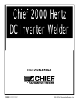
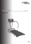
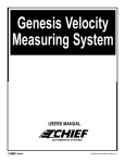
G Series
For: G16, G18 Machines
Parts / Service Manual
R
A
INDUSTRIES COMPANY
2000 © Chief Automotive Systems, Inc.
G SERIES
R
PARTS / SERVICE MANUAL
Parts Ordering Information
To order basic parts and assemblies for the G Series repair system or to request assistance from a Chief Service
Representative, contact the Chief Automotive Systems, Inc. toll-fee hotline answering service in Nebraska (800-4459262) and leave a message. If located outside the United States, contact nearest Chief Automotive Systems, Inc. representative.
When contacting Chief Automotive by telephone (800-445-9262) or mail, provide the following information: name,
name of shop, shop telephone number, and shop address. Additional information needed when ordering includes:
description of part(s), part number(s) and method of payment and shipping.
When ordering, refer to listing of basic parts and assemblies and related illustrations presented in this manual.
NOTE: Chief Automotive Systems, Inc. reserves the right to alter product specifications and/or package
components without notice.
CHIEF’S LIMITED ONE-YEAR
WARRANTY & LIABILITY
Chief Automotive Systems, Inc. warrants for one year from date of installation and/or
purchase any of its products which do not perform satisfactorily due to defect caused
by faulty material or workmanship. Chief’s obligation under this warranty is limited to the repair or replacement of products which are defective and which have not
been misused, carelessly handled, or defaced by repair or repairs made or attempted
by others.
CHIEF AUTOMOTIVE SYSTEMS, INC. DOES NOT ASSUME RESPONSIBILITY FOR ANY DEATH, INJURY OR PROPERTY DAMAGE RESULTING
FROM THE OPERATOR’S NEGLIGENCE OR MISUSE OF THIS PRODUCT
OR ITS ATTACHMENTS. CHIEF MAKES NO WRITTEN, EXPRESS OR
IMPLIED WARRANTY WHATSOEVER OF MERCHANTABILITY OR FITNESS FOR A PARTICULAR PURPOSE OR OTHERWISE REGARDING THE
EQUIPMENT OR ANY PART OF THE PRODUCT OTHER THAN THE LIMITED ONE-YEAR WARRANTY STATED ABOVE.
Returned merchandise requires a “RETURNED GOODS AUTHORIZATION
NUMBER” on the package. Authorization numbers can be obtained by calling or
writing the Customer Service Department, Chief Automotive Systems, Inc. No
returned merchandise will be accepted without an authorization number. All
returned merchandise must be shipped freight prepaid (and may be subject to a 15
percent handling and restocking charge) to:
Chief Automotive Systems, Inc.
Attn: Returned Goods Dept.
1924 E. Fourth St.
P.O. Box 1368
Grand Island, Ne. 68802
800-445-9262
or
Your Authorized
Chief Automotive Systems, Inc.
Representative
G SERIES
R
PARTS / SERVICE MANUAL
Parts (Numbers / Descriptions)
1
2
3
4
5
6
**
7
8
9
10
11
12
13
**
14
**
*
*
*
15
**
**
**
*
*
*
*
**
16
17
18
19
1, 10
15
16
17
18
2, 11
8
9
19
3, 12
7, 14
5
4
*
2
690611
772182
772181
092443
090507
770191
770203
770204
693337
682770
610001
772152
772141
770176
770179
770166
770158
689859
772160
349014
602870
782053
770132
770133
772159
772022
610386
690793
770150
604656
770193
606045
772163
Ref.
Part No.
Description
1
2
610386
690793
601201
707487
1
2
3
4
5
772163
649080
649286
682726
604939
602562
Hyd. Pressure Gauge Ass’y
Portable Gauge Ass’y
Hose, 181/2 x 3/8 x 3/8”SWVLM
Tee, 3/8 x 3/8 x 3/8” Female
Quick Coupler, Female
Swivel Coupler
3
4
5
6
680747
602829
607161
693468
7
8
680755
684975
349014
090023
090023CE
602407
1
1
2
**
(Not shown)
5
3
Ref. Part No.
Tower Head, 5 Ton
Tower Pipe Assembly, 5 Ton
Tower Swing Arm Assembly, 5 Ton
Caster, Swivel, 5”
Foot Pump, Hydraulic
Decal, Chief, 5 Ton Tower
Decal, Ind. Hd/.Arrow, 5 Ton, left
Decal, Ind. Hd./Arrow, 5 Ton, right
Decal, Warning, DO NOT Position
Decal, DO NOT Exceed 6,500 PSI
Tower Head, 10 Ton
Tower Pipe Assembly, 10 Ton
Tower Swing Arm Assembly, 10 Ton
Decal, Chief, 10 Ton Tower
Decal, Ind. Hd./Arrow, left, 10 Ton
Decal, Ind. Hd./Arrow, right, 10 Ton
Decal, CAUTION, Always Push
Ram Assembly, 5 Ton
Ram Assembly, 10 Ton
Hose Assembly
Chain, Tower, 1/2” w/hook
Tower Stop Assembly
Plate Spacer, 1/8”
Plate Spacer, 3/16”
Handle Assembly, 10 Ton
Handle Assembly, 5 Ton
Tower Collar Assembly, 10 Ton
Tower Collar Assembly, 5 Ton
Decal, CAUTION, To Avoid
Bolt, 1/2-13NC x 1 1/4 (5-ton tower)
Lock Nut, 1/2-13NC (5 ton tower)
Bolt, 3/4-10NC x 5 (10 ton tower)
Hydraulic Pressure Gauge Ass’y
(See illustration below or on next pages)
Ref. Part No.
1
Description
Ref. Part No.
4
Description
Description
Tower Collar Assembly, 10Ton
Cast Collar Assembly, 5 Ton
Roller, 5” x 1/2” Chain, Collar, 10Ton
Flat Washer, 1 1/4” ID x 1 7/8” OD x
14Ga.
Pin, Grooved, Cast Collar
Clamp Knob For Idler Collar
Collar, Drilled & Tapped, 10 Ton
Retaining Ring, Heavy Duty Ext.
Series, 5160
Roller, 4 x 3/8 Chain, Collar, 5 Ton
Cast Collar, 3/93
Hose Assembly
120” Hose, 3/8” NPT
120” Hose, 3/8”NPTF, CE
Quick Coupler, Male End
2
3
4
1, 7
2
5, 8
6
1
1
G SERIES
R
Ref. Part No.
1
2
3
4
5
6
7
8
9
10
11
772160
689861
602619
601237
602378
602547
610407
602520
770147
680617
693847
690160
685100
PARTS / SERVICE MANUAL
Description
7
Ram Assembly, Tower, 10 Ton
Ram Assembly, Tower, 5 Ton
Ram Bolt
Flange, Tower
Ram, Tower, 10” Stroke, 10 Ton
Elbow, 90 degree, Female/Male NPT
Ram Base, Flange, Tower Ram (10T)
Hose, 59” x 3/8” NPT
Washer, 1”, Int. Tooth Lock Type A
Flange, Tower
Ram 5 Ton, 8” Stroke, Aux. Tower
Ram Base, Flange, Tower Ram
Hose, 49” x 3/8” NPT Couplings
8
4
9
10
1
2
7
4
3
3
2
5
4
2
Ref. Part No.
1
2
3
4
5
3
5
772159
772022
772158
770104
657782
770103
770105
Description
Handle Assembly, 10 Ton
Handle Assembly, 5 Ton
Bar, Handle, 10 Ton
Bushing, Handle
Grip
Bar, Handle, 5 Ton
Retaining Ring, 1” Bar.
Ref. Part No.
Ref. Part No.
1
2
3
4
4
5
*
*
*
6
7
8
9
10
Description
772161
772000
770148
685100
685100CE
782092
770059
770187
692107
770178
770177
772047
629095
602570
772011
692254
657889
772010
629431
629440
1
2
3
4
5
Mainframe Related
Ramp
Stiff Leg
Pin, Locking, 3/4”
Hose, 49” x 3/8” NPT Coupling
Description
Roller Assembly, Stiff Leg
Nut, 1-8NC Hex Jam, Pl.
Roller, 3” OD x 1 1/4” Wide
Bolt-Bracket Assembly
Bolt, 3/8-16 x 2 1/2” Lg., Gr. 2 Hex, Pl.
Nut, Lock, 3/8-16NC, Pl.
1
Hose, 49” x 3/8” NPTF Coupling CE
3
2
Roller Assembly
Plate, Rear Crossmember
Chief Mainframe Decal
Decal, Serial Number, MF
Chief G16 Decal
Chief G18 Decal
Ready Rod / Pad Assembly - Le
Nut, 1 1/2-6NC, Hex Jam, Gr. , Bl
Spring, Stiff Leg, 105”, Wire
4
6, 7
5
1
3
9
6
5
1
1
11
2
4
8
5
10
2
G SERIES
R
PARTS / SERVICE MANUAL
2
11
6
8
13
12 13 7
3
16
4
15
10
9
14
5
1
Ref. Part No.
1
2
3
4
4
5
6
7
Ref. Part No.
Description
409023
Lift Assembly
770105
602378
604939
685100
685100CE
610124
019010
770139
Retainer Ring, 1” Bar
Ram, Tower, (10” Stroke), 10 Ton
Quick Coupler, Female End
Hose, 49” x 3/8” NPT Coupling
Hose, 49” x 3/8” NPTF Coupling CE
Jack T Assembly
Wrought Washer, 1” ZP
Pin, Grooved, 1.00 x 6.813
8
9
10
11
12
13
14
15
16
Description
092094 Wheel, 6” Lift
602545
408016
770124
408001
707479
707487
693468
770083
Elbow, 90°, Fem/Male NPTF (.016)
Lift Cylinder Pivot Assembly, Bottom
Pin, Grooved, 1.00 x 8
Lift Frame Assembly
Washer, 1” Thrust, Plated
Washer, 1 1/4” Flat, Plated
Retaining Ring, 5160, Heavy Duty
Pin, Grooved, 1 1/4” x 4 7/16”
1
2
3
Ref. Part No.
702077
1
2
3
4
5
6
7
8
9
10
11
12
13
14
15
010630
498102
092110
019095
620736
601682
601666
508281
607380
606686
702068
606855
770092
010079
601738
Description
4
Universal Anchoring System, G Series,
one stand, complete
Bolt, 1/2-13 x 2 1/2 Gr. 8
Pinchweld Clamp Jaw
Spring, Compression, .720 x 1
Washer, 1/2 A-325 ZP
Nut, 1/2-13NC, Gr. 8
Nut, 5/8-11NC, Gr. 8
Bolt, 5/8-11NC x 2.25, Gr. 5
Adapter Tube, UMS (Chief Clamp, Pl.)
Locking Collar
Height Adjusting Pin
Stand Base, Standard Size, G Series
Fastener Bar
Tie-Down Plate
Bolt (G Series), 3/4-10NC x 6, A-325
Washer, 3/4 A-325 ZP
8
6
9
10
7
11
12
13
14
15
3
5
G SERIES
R
PARTS / SERVICE MANUAL
Machine Maintenance
2. Lubricate roller pin and collar ears (each side).
Then turn roller a few times. Roller must turn
freely.
Check and Inspect
These components should be checked prior to use
and anytime a problem is suspected.
CAUTION: To avoid personal injury when
performing any maintenance function, always
wear safety glasses and safety shoes.
Lift Assembly / Stiff Leg Assemblies
!
Clean dirt and grease from all pivot points and
lubricate every two months.
Tower Chains
1. Clean chain before inspecting.
2. Inspect each link for wear, nicks, gouges,
stretched or bent links.
CAUTION: To avoid personal injury or damage to property, DO NOT:
• Heat chain or hook while repairing vehicle.
• Tip load chain hook.
• Pull with twisted chain links.
Air in Hydraulic System
Air Hoses / Hydraulic Lines
1. Separate quick coupler.
2. Place male end of quick coupler in a container
and hold a rag over container and quick coupler.
CAUTION: To avoid personal injury or
damage to property, wear safety
glasses to protect eyes from hydraulic
oil in the event it squirts out of container and past rag.
All air has been removed from hydraulic system at
the factory, but if hydraulic system is opened to
replace one of the system components, it is necessary to bleed air from system prior to using it.
!
Bleeding Air From System At Quick Coupler
Inspect air hoses, hydraulic lines and all couplers for
damage and replace as needed.
!
Cleaning and Lubricating
Tower Heads
Grease tower heads every six months.
1. Remove tower chain from tower head.
2. Remove tower head from tower pipe.
3. Clean dirt from tower head rub pads and where
tower head pipe rubs on inside of tower pipe.
4. Apply grease to tower head pipe and rub pads.
5. Reinstall tower head and tower chain.
3. Press ball check at end of quick coupler against
bottom of container.
CAUTION: To avoid personal injury or
damage to property, DO NOT have any
pressure on the system when pressing
the ball check on quick coupler.
!
4. Press ‘forward’ on foot pump to pump air out of
the system and continue until only hydraulic oil
is being pumped out.
Swing Arm Track
Clean tower arm pivot pins and housings of dirt and
debris. DO NOT lubricate.
5. Reconnect the quick coupler.
Collars
6. With pressure released from system, refill foot
pump reservoir with hydraulic fluid as per manufacturer’s recommendations (packaged with
foot pump).
Clean and lubricate collars monthly.
1. Use compressed air to blow out dirt or dust that
collects between collar ears and rollers.
CAUTION: Wear safety glasses while using
compressed air to blow out dirt and dust.
!
Bleeding Air Beyond Quick Coupler
Contact Chief Automotive Service representative.
4
G SERIES
R
PARTS / SERVICE MANUAL
Specifications (G Series Systems)
G16
Length
Length with Towers Extended
Width
Width with Towers Extended
Width of Treadway
Width between Treadways
Tower Height (5 Ton)
Tower Height (10Ton)
Work Height
Weight
Lifting Capacity
Power Required
Hydraulics
Hydraulic Fluid
Radius of Pull
Controls
Sound Pressure Level
At Control Positions
G18
16” (4.88m)
18’4” (5.58m)
6’10” (2.1m)
9’7” (2.92m)
22 1/2” (571mm)
36 1/2” (927mm)
7’3” (2.2m)
8’2” (2.5m)
25” (635mm)
3,450 lbs. (1,565 kg.)
6,500 lbs. (2,950 kg.)
100 PSI Air Supply (7.0 Bar)
10 Ton (88kN) Hydraulic Rams
1.7L-SUS 215 Viscosity
100° F, 10w Hyd. Fluid
360°
Air-Over-Hydraulic Foot Pump
18’ (5.5m)
20’4” (6.27m)
6’10” (2.1m)
9’7” (2.92m)
22 1/2” (571mm)
36 1/2” (927mm)
7’ 3” (2.2m)
8’ 2” (2.5m)
25” (635mm)
4,150 lbs. (1,882 kg.)
6,500 lbs. (2,950 kg.)
100 PSI Air Supply (7.0 Bar)
10 Ton (88 kN) Hydraulic Rams
1.7L-SUS 215 Viscosity
100° F, 10w Hydraulic Fluid
360°
Air-Over-Hydraulic Foot Pump
82dB(A)
82dB(A)
Optional: Removable Crossmembers, Down Pull Attachment, Portable Wheel Package, Electric Winch
G Series machines are compatible with Genesis, UMS and UGMS for the ultimate in measuring precision.
Hydraulic / Pneumatic Diagram (G Series Machines)
Maximum
Pressure
Safety Relief
Valve
10,000 P.S.I.
(690 BAR)
NOTE: For clarity, the above valves are shown as three position valves when in actuality, they are two position
valves with a three position actuator.
5
Scissor System
Lift Cylinder
Tower Cylinders
R
P.O. Box 1368
Grand Island, Nebraska 68802-1368
Phone: 308/384-9747
Fax:
308/384-8966
INTAIRCO S.A.R.L.
CA de TREMBLAY CHARLES DE GAULLE
18, rue Henri FARMAN
93297 TREMBLAY EN FRANCE CEDEX
TEL 01 41 51 16 80
FAX 01 48 60 09 88
www.chiefautomotive.com
Chief reserves the right to alter product specifications
and/or package components without notice.
FORM GS PM (Rev. 7/00)
Part No. 770171