1
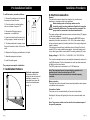
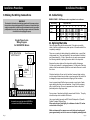
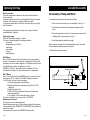
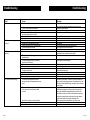
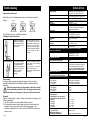
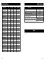
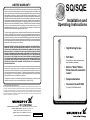
LIMITED WARRANTY
Products manufactured by GRUNDFOS are warranted to the original user only to be free of
defects in material and workmanship for a period of 18 months from date of installation, but
not more than 24 months from date of manufacture. GRUNDFOS' liability under this warranty
shall be limited to repairing or replacing at GRUNDFOS' option, without charge, F.O.B.
GRUNDFOS factory or authorized service station, any product of GRUNDFOS manufacture.
GRUNDFOS will not be liable for any costs of removal, installation, transportation, or any other
charges which may arise in connection with a warranty claim. Products which are sold but not
manufactured by GRUNDFOS are subject to the warranty provided by the manufacturer of
said products and not by GRUNDFOS' warranty. GRUNDFOS will not be liable for damage
or wear to products caused by abnormal operating conditions, accident, abuse, misuse,
unauthorized alteration or repair, or if the product was not installed in accordance with
GRUNDFOS printed installation and operating instructions.
SQ/SQE
Installation and
Operating Instructions
To obtain service under this warranty, the defective product must be returned to the distributor
or dealer of GRUNDFOS products from which it was purchased together with proof of
purchase and installation date, failure date, and supporting installation data. Unless otherwise
provided, the distributor or dealer will contact GRUNDFOS or an authorized service station
for instructions. Any defective product to be returned to GRUNDFOS or a service station must
be sent freight prepaid; documentation supporting the warranty claim and/or a Return Material
Authorization must be included if so instructed.
MANUFACTURER WILL NOT BE LIABLE FOR ANY INCIDENTAL OR CONSEQUENTIAL
DAMAGES, LOSSES, OR EXPENSES ARISING FROM INSTALLATION, USE, OR ANY
OTHER CAUSES. THERE ARE NO EXPRESS OR IMPLIED WARRANTIES, INCLUDING
MERCHANTABILITY OR FITNESS FOR A PARTICULAR PURPOSE, WHICH EXTEND
BEYOND THOSE WARRANTIES DESCRIBED OR REFERRED TO ABOVE. EXCEPT AS
EXPRESSLY HEREIN PROVIDED THE GOODS ARE SOLD "AS IS", THE ENTIRE RISK
AS TO QUALITY AND FITNESS FOR A PARTICULAR PURPOSE, AND PERFORMANCE
OF THE GOODS IS WITH THE BUYER, AND SHOULD THE GOODS PROVE DEFECTIVE
FOLLOWING THEIR PURCHASE, THE BUYER AND NOT THE MANUFACTURER,
DISTRIBUTOR, OR RETAILER ASSUMES THE ENTIRE RISK OF ALL NECESSARY
SERVICING OR REPAIR.
• High Starting Torque
• Soft Start
(2 seconds to reach maximum rpm,
and maximum pressure)
Some jurisdictions do not allow the exclusion or limitation of implied warranties of merchantability
and fitness for a particular purpose, of incidental or consequential damages and some
jurisdictions do not allow limitations on how long implied warranties may last or require you
to pay certain expenses as set forth above. Therefore, the above limitations or exclusions
may not apply to you. This warranty gives you specific legal rights and you may also have
other rights which vary from jurisdiction to jurisdiction.
• Built-in "Smart" Motor
Protection with automatic
restart
The telephone number of our service and repair facilities central directory, from which you can
obtain the locations of our service and repair facilities is, 1-800-333-1366.
• Simple Installation
Federal Communications Commission Notice:
This equipment has been tested and found to comply with the limits for a Class A digital device, pursuant to part 15 of the
FCC Rules. These limits are designed to provide reasonable protection against harmful interference when the equipment
is operated in a commercial environment. This equipment generates, uses, and can radiate radio frequency energy and,
if not installed and used in accordance with the instruction manual, may cause harmful interference to radio communications.
Operation of this equipment in a residential area is likely to cause harmful interference in which case the user will be required
to correct the interference at his own expense.
• Communicate with SQE
(Through CU300 Status Box)
Please leave these instructions with the pump for future reference
Grundfos Pumps Corporation • 3131 N. Business Park Ave., Fresno, CA 93727
Customer Service Centers: Allentown, PA • Fresno, CA
Phone: (800) 333-1366 • Fax: (800) 333-1363
Canada: Oakville, Ontario • Mexico: Apodaca, N.L.
L-SP-TL-017 Rev. 3/30/99
PRINTED IN USA
Visit our website at www.us.grundfos.com
SAFETY
Pre-Installation Checklist
WARNING
Electrical Work
WARNING: Reduced risk of electric shock during operation of this pump
requires the provision of acceptable grounding. If the means of connection to the
supply connected box is other than grounded metal conduit, ground the pump
back to the service by connecting a copper conductor (at least the size of the
circuit supplying the pump) to the grounding screw provided within the wiring
compartment.
Pre-Installation Checklist
1. Well Preparation
If the pump is to be installed in a new well then the well should be fully developed
and bailed or blown free of cuttings and sand. The construction of the GRUNDFOS
SQ/SQE submersibles makes it resistant to abrasion; however, no pump made of
any material can forever withstand the destructive wear that occurs when
constantly pumping sandy water.
If this pump is used to replace an oil-filled submersible or oil-lubricated line-shaft
turbine in an existing well, the well must be blown or bailed clear of oil.
2. Make Sure You Have the Right Pump
Determine the maximum depth of the well, and the
drawdown level at the pump's maximum capacity. Pump
selection and setting depth should be made based on this
data.
3. Pumped Fluid Requirements
Submersible well pumps are designed for pumping clear,
cold water; free of air or gases. Decreased pump
performance and life expectancy can occur if the water is
not clear, cold or contains air or gases. Water temperature
should not exceed 104°F.
Min. 0.5 f/s
Pump dia.
5. Applications
Typical applications:
Groundwater supply for
Fig. 2
- residential housing.
- small waterworks.
- irrigation systems.
- liquid transfer in tanks.
Note: The pump must not be used as a booster pump in a booster
system.
GRUNDFOS MS 3 and MSE 3 submersible motors have water-lubricated
slide bearings. No additional lubrication is required.
I.D.
The submersible motors are factory-filled with a special GRUNDFOS
motor liquid (type SML 2), which will protect the motor fluid down to
-4°F(20°C) and to prevent the growth of bacteria. The level of motor fluid
is important for the operating life of the bearings and consequently the life
of the motor.
Fig. 1
To ensure proper motor cooling refer to the table below for minimum flow
requirements:
Flow velocity
Maximum
past the motor
liquid temperature
0.0 f/s
86° F(30°C)
(free convection)
Page 1
Well Dia.
6. Motor Preparation
A check should be made to ensure that the installation
depth of the pump will always be at least three feet below
the maximum drawdown level of the well. The bottom of the
motor should never be installed lower than the top the
screen or within five feet of the well bottom, as shown in
fig.1.
4. Motor Cooling Requirements
If the pump is to be installed horizontally, e.g. in a
tank, and there is a risk that the pump might be
covered by mud, it must be installed in a flow
sleeve.
Liquid temperatures/cooling
Figure 2 shows an SQ/SQE pump installed in a
well. With the pump operating.
Figure 2 illustrates the following:
- Well diameter.
- Pump diameter.
- Temperature of pumped liquid.
- Flow past the motor to the pump
suction strainer.
Note: The well diameter must be at least 3”. If
there is a risk that the motor will be covered with
sediment then it is recommended the pump be
placed in a Flow Sleeve. The motor should always
be installed above the well screen.
Refilling of motor liquid
It is recommended to refill the motor with GRUNDFOS motor
fluid SML 2.
104°F (40°C)
Page 2
Pre-Installation Checklist
Installation Procedures
To refill the motor, proceed as follows:
8. Electrical connection
1. Remove the cable guard and separate
the pump end from the motor.
Filling plug
2. Place the motor in vertical position
with an inclination of approx. 10°.
3. Remove the filling plug using a
screwdriver or a similar tool.
General
The electrical connection should be carried out by an authorized
electrician in accordance with local regulations.
Before starting work on the pump, make sure the
electricity supply has been switched off and that it cannot be
accidentally switched on. The pump must be grounded. The
pump must be connected to an external mains switch.
6. Replace the filling plug and make sure it is tight.
The supply voltage, rated maximum current and power factor (PF) appear
on the motor nameplate.
The required voltage for GRUNDFOS submersible MS3/MSE3 motors,
measured at the motor terminals, is +6%/–10% of the nominal voltage
during continuous operation (including variation in the supply voltage and
losses in cables).
If the pump is connected to an installation where a Ground Fault circuit
breaker (GFI) is used as additional protection, this circuit breaker must
trip out when ground fault currents with DC content (pulsating DC) occur.
7. Assemble pump end and motor.
Supply voltage:1 x 100-115V or 1 x 200-240 V +6%/–10%, 50/60 Hz.
8. Install the cable guard.
The current consumption can only accurately be measured by means of a
true RMS instrument. If other instruments are used, the value measured
will differ from the actual value.
The SQE pumps can be connected to a CU 300 status box.
4. Inject motor liquid into the motor with
a filling syringe or similar tool,see fig. 3.
5. To allow possible air to escape, move
the motor from side to side. And turn the
shaft.
Fig. 3
The pump is now ready for installation.
7. Installation Postions
Positional requirements
The pump is suitable for
vertical as well as horizontal
installation, however, the
pump shaft must never fall
below the horizontal plane,
see fig. 4.
Note: The pump must never be connected to a capacitor or to
another type of control box other than a CU 300.
The pump must never be connected to an external frequency
converter.
Motor protection
The motor has built-in automatic thermal overload protection and requires
no additional motor protection.
Connection of motor
The motor can be connected directly to the main circuit breaker.
Start/stop of the pump will typically be done via a pressure switch, see
fig. 5.
Note: The pressure switch must be rated for the maximum amps of
the specific pump size.
Fig. 4
Page 3
Page 4
Installation Procedures
Installation Procedures
9. Making the Wiring Connections
10. Cable Sizing
SINGLE-PHASE
WARNING!
Reduced risk of electric shock during operation of this pump requires
the provision of acceptable grounding. If the means of connection to the
supply connected box is other than grounded metal conduit, ground the
pump back to the service by connecting a copper conductor, at least the
size of the circuit supplying the pump.
Motor Rating
10 2- Wire Pump
with Ground
Quick Disconnect
Pressure
Switch
Black
Black
Green
Pump & Motor
Maximum Cable Length Motor Service to Entrance
Copper Wire Size
VOLTS
HP
14
12
10
8
6
4
2
0
115
1/3
1/2
1/3
1/2
3/4
130
100
550
400
300
250
190
210
160
880
650
480
400
310
340
250
1390
1020
760
630
480
540
390
2190
1610
1200
990
770
840
620
3400
2510
1870
1540
1200
1300
960
5250
3880
2890
2380
1870
1960
1460
7960
5880
4370
3610
2850
2910
2160
230
1
1 1/2
Single-Phase 2-wire
Wiring Diagram
for GRUNDFOS Motors
60 HZ
6470
5360
4280
00
6520
5240
11. Splicing the Cable
Splice the drop cable with the motor cable. If the splice is carefully
made, it will be as efficient as any other portion of the cable and will be
completely watertight.
There are a number of cable splicing kits available today - epoxy filled,
rubber-sealed, etc. Many perform well if the manufacturer's directions
are followed carefully. If one of these kits is not used, we recommend
the following method for splicing the motor cable to the drop cable:
Examine the motor cable and the drop cable carefully for damage.
Cut the motor leads off in a staggered manner. Cut the ends of the drop
cable so that the ends match up with the motor leads. Be sure to match
the colors.
Strip back and strip off one-inch of insulation from each lead, making
sure to scrape the wire bare to obtain a good connection. Be careful not
to damage the copper conductor when stripping off the insulation.
Insert a properly sized Sta-Kon-type connector on each pair of leads,
again making sure that colors are matched. Using Sta-Kon crimping
pliers, indent the lugs. Be sure to squeeze down hard on the pliers,
particularly when using large cable.
Form a piece of electrical putty tightly around each Sta-Kon. The putty
should overlap on the insulation of the wire.
A capacitor or control box should NEVER be
connected to a SQ/SQE submersible pump
Fig. 5
Page 5
Use a good quality tape such as #33 Scotch Waterproof or Plymouth
Rubber Company Slipknot Grey.
Wrap each wire and joint tightly for a distance of about 2½ inches
on each side of the joint.
Make a minimum of four passes over each joint and overlap each
pass approximately one inch to assure a completely watertight seal.
Page 6
Installation Procedures
Installation Procedures
General
Note: Do not lower or lift the pump by means of the motor cable.
14. Piping
•
The pump should only be gripped by the
two flats at the top of the pump, as shown
in fig. 9.
•
The pump can be installed vertically or
horizontally. During operation, the pump
must always be completely submerged in
water.
•
When plastic pipe is used, a stainless
steel safety wire is recommended for
lowering and lifting the pump. Fasten
the wire to the eyelet on the pump, as
shown in fig. 10.
•
The threaded joints must be well cut
and fit together tightly to ensure that
they do not work loose.
The loose data plate supplied with the pump should be placed close to the
installation site.
12. Installing the cable plug to
the motor
The cable plug supplied with the motor is factorygreased. Check that the plug is greased correctly.
To install the cable plug, proceed as follows:
1.Check that the cable is of the correct type,
cross-section and length.
2.Check that the mains on the location has
correct connection to ground.
3.Check that the motor socket is clean and dry.
4.Press the cable plug into the motor socket.
The plug will only fit one way, see fig. 6.
5.Install and tighten the four nuts, see fig. 6.
When the plug has been installed, there must
not be a clearance between the motor and the
cable plug.
Fig. 6
Fig. 9
15. Installing the Pump
Fig. 10
Installation Depth
The dynamic water level should always be
above the pump see fig. 11.
13. Installing the
cable guard
A = Dynamic water level
B = Static Water Level
C = Minimum 3" well diameter
D = Drawdown
E = Installation depth below static
water level. Maximum 500 feet
To fit the cable guard, proceed as
follows:
1. Make sure that the motor lead
lies flat in the cable guard.
2. The two flaps of the cable
guard must engage with the
upper edge of the pump
sleeve, see fig. 7.
A
B
D
Procedures
To install the pump, follow these steps:
E
1. Install the enclosed data plate sticker at the
well head.
Fig. 7
3. Fasten the cable guard to the cable
plug with the four screws supplied, see
fig. 8.
2. Check the well for proper clearance — the
well must be at least 3" in diameter. It is a
good idea to check the well for clearance
using a plumb ring (2.95 ø x 10 in.).
3. Attach the first section of riser pipe to the
pump.
C
Fig. 11
Fig. 8
Page 7
Page 8
Installation Procedures
Installation Procedures
General
Note: Do not lower or lift the pump by means of the motor cable.
14. Piping
•
The pump should only be gripped by the
two flats at the top of the pump, as shown
in fig. 9.
•
The pump can be installed vertically or
horizontally. During operation, the pump
must always be completely submerged in
water.
•
When plastic pipe is used, a stainless
steel safety wire is recommended for
lowering and lifting the pump. Fasten
the wire to the eyelet on the pump, as
shown in fig. 10.
•
The threaded joints must be well cut
and fit together tightly to ensure that
they do not work loose.
The loose data plate supplied with the pump should be placed close to the
installation site.
12. Installing the cable plug to
the motor
The cable plug supplied with the motor is factorygreased. Check that the plug is greased correctly.
To install the cable plug, proceed as follows:
1.Check that the cable is of the correct type,
cross-section and length.
2.Check that the mains on the location has
correct connection to ground.
3.Check that the motor socket is clean and dry.
4.Press the cable plug into the motor socket.
The plug will only fit one way, see fig. 6.
5.Install and tighten the four nuts, see fig. 6.
When the plug has been installed, there must
not be a clearance between the motor and the
cable plug.
Fig. 6
Fig. 9
15. Installing the Pump
Fig. 10
Installation Depth
The dynamic water level should always be
above the pump see fig. 11.
13. Installing the
cable guard
A = Dynamic water level
B = Static Water Level
C = Minimum 3" well diameter
D = Drawdown
E = Installation depth below static
water level. Maximum 500 feet
To fit the cable guard, proceed as
follows:
1. Make sure that the motor lead
lies flat in the cable guard.
2. The two flaps of the cable
guard must engage with the
upper edge of the pump
sleeve, see fig. 7.
A
B
D
Procedures
To install the pump, follow these steps:
E
1. Install the enclosed data plate sticker at the
well head.
Fig. 7
3. Fasten the cable guard to the cable
plug with the four screws supplied, see
fig. 8.
2. Check the well for proper clearance — the
well must be at least 3" in diameter. It is a
good idea to check the well for clearance
using a plumb ring (2.95 ø x 10 in.).
3. Attach the first section of riser pipe to the
pump.
C
Fig. 11
Fig. 8
Page 7
Page 8
Installation Procedures
Operating the Pump
16. Installing the Pump(cont.)
4. Lower the pump into the well. Make sure the motor cable is not
damaged when the pump is lifted or lowered into the well —
especially in 3" wells. NOTE: Do not lower or lift the pump
using the motor cable.
5. When the pump has been installed to the required depth, the
installation should be finished by means of a well seal. Note that
the dynamic water level should always be above the pump.
6. Loosen the safety wire so that it becomes unloaded and lock it to
the well seal using a cable clamp.
7. Attach the supplemental information label at the electrical
installation site.
8. Complete the electrical connections. Remember that a
capacitor or a control box should NEVER be connected to a
SQ/SQE submersible pump.
Installation depths
Maximum installation depth: below the static water level: 500 feet,
Minimum installation depths: 1.75' below the dynamic water level:
Vertical installation:
During start-up and operation, the pump must always be
completely submerged in water.
Horizontal installation:
The pump must be installed at least 1.75 ft. below the
dynamic water level. If there is a risk that the pump might be
covered by mud, the pump must always be placed in a flow
sleeve.
Note: Do not lower or lift the pump with the motor cable.
17. Generator Operation
• It is OK to operate the SQ/SQE with a generator.
The generator must be sized 10% above the pumps P1 (Input
Power) values.
Motor HP
1/3 - 1/2 A
1/2 - 3/4 B
1- 11/2 C
Page 9
18. Starting the Pump for the First Time
When the pump has been connected correctly, the pump should be
started with the discharge valve closed approximately one-third. Due
to the soft start feature, the pump takes approximately 2 seconds to
develop full pressure.
Motor Cooling and Other Considerations
• Make sure the well is capable of yielding a minimum quantity
of water corresponding to the pump capacity.
• Do not start the pump until it is completely submerged in the
liquid.
• As the valve is being opened, the drawdown should be checked to
ensure that the pump always remains submerged.
• To ensure the necessary cooling of the motor, the pump should
never be set so low that it gives no water. If the flow rate
suddenly falls, the reason might be that the pump is pumping
more water than the well can yield. The pump must immediately
be stopped and the fault remedied.
Water Impurities
• If there are impurities in the water, the valve should be opened
gradually as the water becomes clearer. The pump should not be
stopped until the water is clean, otherwise the pump parts and the
check valve may become clogged.
• When the water is clean the valve should be fully opened.
Minimum flow rate
• To ensure the necessary cooling of the motor, the pump flow rate
should never be set to a value lower than .2 gpm. If the flow rate
suddenly falls, the reason might be that the pump is pumping
more water than the well can yield. The pump must be
stopped and the fault corrected.
Note:
The pump's dry-running protection is effective only within
the recommended duty range of the pump.
Note:
Do not let the pump run against a closed discharge valve for
more than 5 minutes. When the discharge valve is closed,
there is no cooling flow and there is a risk of overheating in
motor and pump.
Min. Generator Size (Watts)
1000
1700
2000
Page 10
Assembly/Disassembly
Operating the Pump
Built-in protection
The motor incorporates an electronic unit which protects the motor in
various situations.
In case of overload, the built-in overload protection will stop the pump for
5 minutes. After that period, the pump will attempt to restart.
If the pump is started and the well has not recovered, the pump will stop
after 30 seconds.
If the pump has been stopped as a result of dry running, it will start
automatically after 5 minutes.
Resetting the pump:
Switch off the electricity supply for 1 minute.
The motor is protected against the following conditions:
- dry running,
- voltage surges (up to 5000 V),
- overvoltage,
- undervoltage,
- overload
- overtemperature.
19. Assembly of Pump and Motor
To assemble pump end and motor, proceed as follows:
1. Place the motor horizontally in a vice and tighten it, see fig. 12.
2. Grease the motor shaft end with the grease supplied with the
motor.
3. Screw the pump end on the motor. A spanner may be used on the
clamping faces of the pump part, see fig.12.
4. Install cable guard as described on page 7.
When pump end and motor have been assembled correctly, there must
not be a clearance between pump end and motor.
To disassemble reverse procedure.
MS 3 Motors:
Note: All MS 3 motors are factory set to detect dry running conditions.
However, it is important to ensure that the configurations of both the SQ
pump and motor are the same configuration. Configurations can be found
on both SQ pump and motor nameplates as “ Config.”
EXAMPLE: Config. A-2, must match the other nameplate A-2. See
Technical Data on page 17 for quick referencing on all configurations.
MSE 3 Motors:
Note: To set Dry-Run limit in the MSE/SQE pumps, you need to connect
the pump to a CU 300. Refer to CU 300 I&O for proper connections.
To set Dry-Run protection, follow these steps:
1. Start the pump against closed discharge.
2. Rapidly read the power consumption value (W) in the R100
display 2.5.
3. Multiply this value by 0.9.
4. Within the R100, go to display 4.6 and enter the new value
(minimum power limit).
5. Go to display 4.7 and change the setting to “Active”.
For further information on dry-running, refer to CU 300 I&O.
Maintenance and service:
The pumps are normally maintenance-free.
Deposits and wear may occur. For that purpose, service kits and service
tools are available from GRUNDFOS. The GRUNDFOS Service Manual is
available on request.
The pumps can be serviced at a GRUNDFOS service center.
Page 11
Use pump vise here.
2.91"
70
mm
301.2"
mm
Fig. 12
Page 12
Troubleshooting
Fault
1. The pump does not run
2. The pump runs but gives
no water.
3. The pump runs at reduced
capacity.
4. Frequent starts and stops.
Troubleshooting
Cause
a. The fuses are blown
b. The GFI circuit breaker has tripped.
c. No electricity supply.
d. The motor protection has cut off the
electricity supply due to overload.
e. The drop cable is defective.
f. Overvoltage has occured.
a. The discharge is closed.
b. No water or too low water level in well.
c. Check valve is stuck in it’s closed position.
d. The suction strainer is closed.
e. The pump is defective.
a. The drawdown is larger than anticipated.
b. The valve s in the discharge pipe are partly
closed/blocked.
c. The discharge pipe is partly chocked by
impurities (Iron bacteria).
d. The non- return valve of the pump is blocked.
e. The pump and the riser pipe are partly choked
by impurities (Iron bacteria).
f. The pump is defective.
g. Hole in discharge pipe.
h. The riser pipe is defective.
i. Undervoltage has occurred.
a. The differential of the pressure switch
between the start and stop pressures is too
small.
b. The water level electrodes or level switches
in the reservior have not been installed
correctly
c. Checkvalve is leaking or stuck half-open.
d. The supply voltage is unstable.
e. The motor temperature is too high.
Page 13
Remedy
Replace the blown fuses. If the new fuses blow
too, check the electrical installation and the drop cable.
Reset the circuit breaker.
Contact the Electricity provider.
Check for motor/pump blockage.
Repair/replace the pump/cable.
Check the electricity supply
Open the valve
See item 3a.
Pull the pump and clean or replace the valve.
Pull the pump and clean the strainer.
Repair/replace the pump.
Increase the installation depth of the pump, throttle the pump
or replace it with a smaller capacity model.
Check and clean/replace the valves as necessary.
Clean/rplace the dischrge pipe.
Pull the pump and check/replace the valve.
Pull out the pump. Check and clean or replace the pump, if
necessary. Clean the pipes.
Repair/replace the pump.
Check and repair the piping.
Replace.
Check the electricity supply.
Increase the differential. However, the stop pressure must
not exceed the operating pressure of the pressure tank, and
the start pressure should be high enough to ensure sufficient
water supply.
Adjust the intervals of the electrodes/level switches to ensure
suitable time between the cutting-in and cutting-out of the
pump. See installation and operating instructions for the
automatic devices used. If the intervals between start/stop
cannot be changed via the automatics, the pump capacity
may be reduced by throttling the discharge valve.
Pull the pump and clean/replace the non-return valve.
Check the electrical supply.
Check the water temperature.
Page 14
Troubleshooting
Fault
1. The pump does not run
2. The pump runs but gives
no water.
3. The pump runs at reduced
capacity.
4. Frequent starts and stops.
Troubleshooting
Cause
a. The fuses are blown
b. The GFI circuit breaker has tripped.
c. No electricity supply.
d. The motor protection has cut off the
electricity supply due to overload.
e. The drop cable is defective.
f. Overvoltage has occured.
a. The discharge is closed.
b. No water or too low water level in well.
c. Check valve is stuck in it’s closed position.
d. The suction strainer is closed.
e. The pump is defective.
a. The drawdown is larger than anticipated.
b. The valve s in the discharge pipe are partly
closed/blocked.
c. The discharge pipe is partly chocked by
impurities (Iron bacteria).
d. The non- return valve of the pump is blocked.
e. The pump and the riser pipe are partly choked
by impurities (Iron bacteria).
f. The pump is defective.
g. Hole in discharge pipe.
h. The riser pipe is defective.
i. Undervoltage has occurred.
a. The differential of the pressure switch
between the start and stop pressures is too
small.
b. The water level electrodes or level switches
in the reservior have not been installed
correctly
c. Checkvalve is leaking or stuck half-open.
d. The supply voltage is unstable.
e. The motor temperature is too high.
Page 13
Remedy
Replace the blown fuses. If the new fuses blow
too, check the electrical installation and the drop cable.
Reset the circuit breaker.
Contact the Electricity provider.
Check for motor/pump blockage.
Repair/replace the pump/cable.
Check the electricity supply
Open the valve
See item 3a.
Pull the pump and clean or replace the valve.
Pull the pump and clean the strainer.
Repair/replace the pump.
Increase the installation depth of the pump, throttle the pump
or replace it with a smaller capacity model.
Check and clean/replace the valves as necessary.
Clean/rplace the dischrge pipe.
Pull the pump and check/replace the valve.
Pull out the pump. Check and clean or replace the pump, if
necessary. Clean the pipes.
Repair/replace the pump.
Check and repair the piping.
Replace.
Check the electricity supply.
Increase the differential. However, the stop pressure must
not exceed the operating pressure of the pressure tank, and
the start pressure should be high enough to ensure sufficient
water supply.
Adjust the intervals of the electrodes/level switches to ensure
suitable time between the cutting-in and cutting-out of the
pump. See installation and operating instructions for the
automatic devices used. If the intervals between start/stop
cannot be changed via the automatics, the pump capacity
may be reduced by throttling the discharge valve.
Pull the pump and clean/replace the non-return valve.
Check the electrical supply.
Check the water temperature.
Page 14
Technical Data
Troubleshooting
supply Voltage:
Instruments not allowed:
Note: The use of the following instruments is not allowed during fault
finding:
Insulation
Test
Resistance
Test
High-voltage
Test
Note: When measuring, use RMS-instruments.
Checking the motor and cable:
Measure the voltage L1
(RMS) between phase and
L2. Connect the voltmeter
to the terminals at the
connections.
Measure the current (RMS)
while the pump is operating
at a constant discharge
head(if possible, at capacity
where the motor is heavily
loaded). For maximum
current, see motor
nameplate.
The voltage should, when the
motor is loaded, be within the
range specified on Page 4, large
variations in supply voltage
indicate poor electricity supply,
and the pump should be stopped
until the problem has been
corrected.
If the current exceeds the full load
current, there are the following
possible faults:
Poor connection in the leads,
possibly in the cable joint.
Too low supply voltage, see item 1
on Page 13.
Environment
During handling, operation, storage and transport, all environment
regulations dealing with the handling of hazardous materials must be
observed.
When the pump is taken out of operation, it must be ensured
that no hazardous material is left in the pump and in the riser
pipe, which can be injurous to persons and the environment.
Disposal
Disposal of this product or parts of it must be carried out according to the
following guidelines:
1. Use the local public or private waste collection service.
2. If such waste collection service does not exist or cannot handle the
materials used in the product, please deliver the product or any
hazardous materials from it to your nearest GRUNDFOS company or
service center.
Page 15
1x200-240V +6%/-10%, 50/60 Hz, PE
1x100-115V +6%/-10%, 50/60 Hz, PE
Operation via Generator:
As a minimum, the generator output
must be equal to the motor P1[KW] +10%
Starting Current:
The motor starting current is equal to the
highest value stated on the motor nameplate
Starting:
Soft starting
Run-up Time:
Maximum : 2 seconds
Motor Protection:
The motor is protected against:
Dry running, overvoltage, undervoltage,
overload, overtemperature
Power Factor:
PF= 1
Service Factor:
0.33-0.50A[HP]-1.75 at 115V/230V
0.50-0.75A[HP]-1.4 at 230V
1.0 -1.5C[HP] -1.15 at 230V
Motor Cable:
3 Wire, 14 AWG XLPE
Length
5 ft
Motor Liquid:
Type SML 2
pH Values:
SQ and SQE: 5 to 9
Liquid Temperature:
The temperature of the pumped liquid must
not exceed 104°F.
Note: if liquids with a viscosity higher than that of water are to be pumped,
please contact GRUNDFOS
Discharge Port:
5SQ/SQE- 1"NPT
10-15SQ/SQE- 1 1/4" NPT
22-30SQ/SQE- 1 1/2" NPT
STORAGE CONDITIONS
Minimum Ambient Temperature:
-4°F
Maximum Ambient Temperature:
+140°F
Freeze Protection:
If the pump has to be stored after use, it
must be stored on a frost-free location or it
must be ensured that the motor liquid is
frost-proof. (The motor must be stored
without being filled with motor liquid.)
OPERATING CONDITIONS
Minimum Ambient Fluid Temperature:
-4°F
Maximum Ambient Fluid Temperature:
+104°F
APPROXIMATE DIMENSIONS AND WEIGHT
Motor Dimensions (MS 3 & MSE 3):
0.33-0.50A[hp]
20.9" length x 2.68" diameter
0.50-0.75B[hp]
20.9" length x 2.68" diameter
1.0-1.5C[hp]
22.3" length x 2.68" diameter
Motor Weights (MS 3 & MSE 3):
0.33-0.50A[hp]
6.0 Lbs
0.50-0.75B[hp]
7.1 Lbs
1.0-1.5C[hp]
8.2 Lbs
Pump End Dimensions:
Pump Diameter:
2.68"
Pump Diameter, incl. cable guard:
2.91"
Pump End Dimensions(min. and max.):
5SQ/SQE
10.6" to 18.0"
10SQ/SQE
10.6" to 16.9"
15SQ/SQE
10.6" to 16.9"
22SQ/SQE
10.6" to 16.9"
30SQ/SQE
10.6" to 13.7"
Pump End Weights(min. and max.):
All SQ/SQE Models
2.2 lbs to 3.5 lbs
Well Diameter (minimum):
3"
Installation Depth (Maximum):
500 feet, below static water level.
Page 16
Technical Data
Technical Data
HP
VOLTAGE
CONFIG.
5SQ/SQE03A-90
5SQ/SQE03A-140
5SQ/SQE05A-180
5SQ/SQE05B-230
5SQ/SQE05B-270
5SQ/SQE07B-320
5SQ/SQE10C-360
5SQ/SQE10C-410
5SQ/SQE10C-450
PUMP TYPE
1/3 A
1/3 A
1/2 A
1/2 B
1/2 B
3/4 B
1C
1C
1C
230V/115V
230V/115V
230V/115V
230V
230V
230V
230V
230V
230V
A-2
A-4
A-5
B-8
B-9
B-6
C-2
C-10
C-7
3.9/7.8
3.9/7.8
4.9/9.8
4.9
4.9
7.6
7.6
7.6
7.6
10SQ/SQE03A-110
10SQ/SQE05A-160
10SQ/SQE05B-200
10SQ/SQE07B-240
10SQ/SQE10C-290
10SQ/SQE10C-330
10SQ/SQE15C-380
1/3 A
1/2 A
1/2 B
3/4 B
1C
1C
1 1/2 C
230V/115V
230V/115V
230V
230V
230V
230V
230V
A-2
A-4
B-3
B-4
C-2
C-9
C-5
3.9/7.8
4.9/9.8
4.9
7.6
7.6
7.6
11.1
15SQ/SQE03A-70
15SQ/SQE05A-110
15SQ/SQE05B-150
15SQ/SQE07B-180
15SQ/SQE10C-220
15SQ/SQE10C-250
15SQ/SQE15C-290
1/3 A
1/2 A
1/2 B
3/4 B
1C
1C
1 1/2 C
230V/115V
230V/115V
230V
230V
230V
230V
230V
A-1
A-3
B-1
B-5
C-1
C-3
C-9
3.9/7.8
4.9/9.8
4.9
7.6
7.6
7.6
11.1
22SQ/SQE03A-40
22SQ/SQE05A-80
22SQ/SQE05B-120
22SQ/SQE07B-160
22SQ/SQE10C-190
22SQ/SQE15C-220
1/3 A
1/2 A
1/2 B
3/4 B
1C
1 1/2 C
230V/115V
230V/115V
230V
230V
230V
230V
A-7
A-6
B-2
B-5
C-4
C-6
3.9/7.8
4.9/9.8
4.9
7.6
7.6
11.1
30SQ/SQE05A-40
30SQ/SQE05B-90
30SQ/SQE10C-130
30SQ/SQE15C-170
1/2 A
1/2 B
1C
1 1/2 C
230V/115V
230V
230V
230V
A-1
B-7
C-8
C-2
4.9/9.8
7.6
7.6
11.1
Page 17
ACCESSORIES
MAX. AMPS
PRODUCT
PART NUMBER
CU 300
96422776
FLOW SLEEVE
96037505
GREASE
96037562
FLOW SWITCH .5 GPM 5-15SQE
96022967
FLOW SWITCH 1 GPM 22-30SQE
96022970
PRESSURE TRANSMITTER
96026030
CONSTANT PRESSURE KIT: 5-15SQE
96022968
(Includes CU300, Pressure Transducer & .5 GPM Flow Switch)
CONSTANT PRESSURE KIT: 22-30SQE
96022971
(Includes CU300, Pressure Transducer & 1 GPM Flow Switch)
Notes
Page 18
Technical Data
Technical Data
HP
VOLTAGE
CONFIG.
5SQ/SQE03A-90
5SQ/SQE03A-140
5SQ/SQE05A-180
5SQ/SQE05B-230
5SQ/SQE05B-270
5SQ/SQE07B-320
5SQ/SQE10C-360
5SQ/SQE10C-410
5SQ/SQE10C-450
PUMP TYPE
1/3 A
1/3 A
1/2 A
1/2 B
1/2 B
3/4 B
1C
1C
1C
230V/115V
230V/115V
230V/115V
230V
230V
230V
230V
230V
230V
A-2
A-4
A-5
B-8
B-9
B-6
C-2
C-10
C-7
3.9/7.8
3.9/7.8
4.9/9.8
4.9
4.9
7.6
7.6
7.6
7.6
10SQ/SQE03A-110
10SQ/SQE05A-160
10SQ/SQE05B-200
10SQ/SQE07B-240
10SQ/SQE10C-290
10SQ/SQE10C-330
10SQ/SQE15C-380
1/3 A
1/2 A
1/2 B
3/4 B
1C
1C
1 1/2 C
230V/115V
230V/115V
230V
230V
230V
230V
230V
A-2
A-4
B-3
B-4
C-2
C-9
C-5
3.9/7.8
4.9/9.8
4.9
7.6
7.6
7.6
11.1
15SQ/SQE03A-70
15SQ/SQE05A-110
15SQ/SQE05B-150
15SQ/SQE07B-180
15SQ/SQE10C-220
15SQ/SQE10C-250
15SQ/SQE15C-290
1/3 A
1/2 A
1/2 B
3/4 B
1C
1C
1 1/2 C
230V/115V
230V/115V
230V
230V
230V
230V
230V
A-1
A-3
B-1
B-5
C-1
C-3
C-9
3.9/7.8
4.9/9.8
4.9
7.6
7.6
7.6
11.1
22SQ/SQE03A-40
22SQ/SQE05A-80
22SQ/SQE05B-120
22SQ/SQE07B-160
22SQ/SQE10C-190
22SQ/SQE15C-220
1/3 A
1/2 A
1/2 B
3/4 B
1C
1 1/2 C
230V/115V
230V/115V
230V
230V
230V
230V
A-7
A-6
B-2
B-5
C-4
C-6
3.9/7.8
4.9/9.8
4.9
7.6
7.6
11.1
30SQ/SQE05A-40
30SQ/SQE05B-90
30SQ/SQE10C-130
30SQ/SQE15C-170
1/2 A
1/2 B
1C
1 1/2 C
230V/115V
230V
230V
230V
A-1
B-7
C-8
C-2
4.9/9.8
7.6
7.6
11.1
Page 17
ACCESSORIES
MAX. AMPS
PRODUCT
PART NUMBER
CU 300
96422776
FLOW SLEEVE
96037505
GREASE
96037562
FLOW SWITCH .5 GPM 5-15SQE
96022967
FLOW SWITCH 1 GPM 22-30SQE
96022970
PRESSURE TRANSMITTER
96026030
CONSTANT PRESSURE KIT: 5-15SQE
96022968
(Includes CU300, Pressure Transducer & .5 GPM Flow Switch)
CONSTANT PRESSURE KIT: 22-30SQE
96022971
(Includes CU300, Pressure Transducer & 1 GPM Flow Switch)
Notes
Page 18