1
~. LEARJET 25D~F
MUUNTENANGEMANUAL
Page 1 of 16
;
Date
7 ~?5-- {/
ACTT
2~83
Lnd's
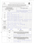
The following is ~ list of all scheduled inspections contained in the Learjet
Inspection Pro~am and the overall interval for each inspection.
Complied With
S(R
cf
Due.
(1) Phases A1-6 lEach A-Phase Due Every 300 Hours or 12 Months.
(2) Phases Bl-6 lEach B-Phase Due Every 600 Hours or 24 Months.
5--10:10
i
,
i
(3) Phases Cl-6 Each C-Phase Due Every 1,200 Hours or 48 Months.
,
(4) Phases D1-6 Each D-Phase Due Every 2,400 Hours or 96 Months.
,51'23
(5) 3,000 Landing Inspection - Due Every 3,000 Landings.
~
!
(6) Major Landing Gear Inspection - Due Every 6,000 Landings .
..••
»:
i
(7) 12 Year Airframe Inspection - Due Every 12 Years or 6,000 Landings. _3<...L---"g~---,-D~t;;b,--_---,----<3...L---'~g""",---...:.../"",-g
(8) 12,000 Hour Airframe Inspection - Initial Due at first 12,000
I
HourslRepeaf Due Every 6,000 Hours thereafter.
Thrust Reversers!
j
Dee Howard
Wing
300 Hour
600 Hour
;c200C)
AW
it
1200 Hour
t(
2400 Hour
((
12 Year
{ (
~
LEARJET 25 DEF
N l(qq
(b1J
Page 2 of 16
7-- 8~![
Date
/ I
ACTT
S'3 ~ )5
Complied With
5 [8 L/
Lnd's
Due
,
FAR 91.411
Alltimeters
System
LIH RIH Stby.
Co-2r-- II
;
(p- dCC--- IJ
\
FAR 91.413
Transponder
RVSM
RVSM
Air Data
RVSM
Inspections
I
RVSM
Alt. Hold
24 Month
~
c§~
24 Month
12 Month
I
i
First Aid Kit
U Month
i
Weight & Bal 3;6Month
~
/U!1
135
Register ELT 1~ Month
Clock Battery If Month
Avionic Insp. 12 Month
135
Fuel Cal.
12 Month
135
:IflJli
•
Compass Card 1~Month
135
AJA
It Month
135
Emer. Equip.
leA's
-A c~ 4-
"fat;, Ej~ 1 idMO
A (J ~ d-'-OI~()5
ff/
i
r~ ex
f\!1
,H
1
r'\ /"
lJuUJ
P
OCr
~;I-?randLt
H
-(,41-
r---..
LEARJET 25 D~F
Page 3 of 16
7- <6- ) (
Date
N~
S-S3?3
ACTT
Complied With
Engine # 1 SIN;
C::r&/D-'6/1
f)I ( -Q ~~g;t
Total Time
300 Houri ,
50<;9
600 Houri
5-(0 <{
J
.5S5;lt -:
Cycles
,
Due
S
ctCf-
Due
f9ci9
Due
G2-cr?
bby9
Due
(Q fpc{7
ffOI·'S
Due
1
i
1000 Hour,
1
5000 Hour OIR
wlf
5 Year Corrosion
!
I
7~/'i-([)
10 Year Oorrosion
(>O;t1p~~{J'1de
Engine # 2 SIN1 dtl-
c;r(PI 0--'3 A
?c~
0 32
I
!It
Total Time
If)
IJB
Due
7-/ '1-;;,0
Due
1J/ILf
51£53
'5
of
~5'JV
(Pt;tJ)O
Cycles
5(8'4
300 Hour!
5" fOLI J
Due
57L/9
600 Hour!
S049
Due
fa dlf7
1000 Hour
c-Cf'3
b' /
Due
S oj
5000 HoUr OIR
5 Year Corrosion
10 Year Corrosion
!
I
i
'3
Due
jdA
Due
g- - r'B'''-D9
CC7/V{ fJ ~ e4-1 CJ-1,- t!r' cl!-t fJa.c:
"1
,lL! 254
Lnd's
5
Due
iJw
foOl
'3
ia Df3
J1)/i
5-IF--J?
~uDDt!f)J
LEARJET 25B/OJD/F
MAINTENANCE I MANUAL
INSPECTION/CHECKS
INTERVALS
!
Page 40f16
5-10-29
WITH SPECIAL REQUIREMENTS OR INSPECTION/CHECKS
DUE AT OTHER
1. Description
•
A. This schedule i~ a list of inspection checks which do not correspond with the regularly scheduled
inspections within the approved Learjet Manufacturer's Inspection Program or that have special
requirements attached to the inspection item.
S. Items listed as que per a vendors recommended schedule will require research to determine the
required inspection interval for that item and should be noted for future reference.
2. Inspection Items
IRN INSPECTION{CHECK
INTERVAL
CABIN
P2561 005 Perform inspection of life vest. Perform inspection in accordance with
i
~M~a~n~u~fa~c~tu~r~e~(~s~in~s~t~ru~c~t~io~n~s~
R2620030 Perform ICC Hydrostatic Test of portable hand-held fire extinguisher.
NOTE: iPortable hand-held fire extinguishers may either be hydro.
tested or replaced at this time. Initial time count for replacement or
testing
this item shall commence from the manufacturing date
stamp~d on the item.
!ltA.vt {! ],,:; d~1",,-2...!.:Ye=a=rs~;J,-·
=O=O,-CZ)~
pf
A
COCKPIT
C2213007 Disassemble roll servo (clutch-type) (PIN 2380066). Clean and inspect
for corrosion. Relubricate, assemble, and replace motor and clutch
brushes as required. NOTE: In order to accomplish this requirement,
the performing facility must possess Repair Manual No. RM-103, dated
June 1@82(or later), applicable to PIN 2380066-11, -21, -26, -44, -47,
-50 -51 -67 -69 thru -73 -75 and -79 thru -81
600 Hours
C2213008 Replace roll servo (clutch-type) (PIN 2380066) bearings. NOTE: In
order tq accomplish this requirement, the performing facility must
possess Repair Manual No. RM-103, dated June 1982 (or later),
applicable to PIN 2380066-11, -21, -26, -44, -47, -50, -51, -67, -69
thru -73, -75, and -79 thru -81.
1,800 Hours
C2213009 Inspect! replace, or repair roll servo (clutch-type) (P/N2380066)
commutator.NOTE: In order to accomplish this requirement, the
perfor~ing facility must possess Repair Manual No. RM-103, dated
June 1~82 (or later), applicable to PIN 2380066-11, -21, -26, -44, -47,
-50, -51, -67, -69 thru -73, -75, and -79 thru -81.
1,800 Hours
N3510015 Comply with factory overhaul of BIE Aerospace (Puritan-Bennett)
crew oxyqen masks (if installed). NOTE: On masks that have been
in service for more than six years, comply with factory overhaul at
the ne>ct300 Hour/12 Month inspection.
"'?
:
Ill.f/
0
6 Years O!- __
I
l'
I
J
I
•
I
y ~>- d--
-D7
~ __
A I I)
~/~U/_VV
__
~c:i-,-o;2O::.;'"'=:..-=-·
LEARJET 25B/C1D/F
MAINTENANCE IMANUAL
ELECTRICAL
Page 5 of 16
5-10-29
I
G1222001 Lead Acid Batteries - (Effective on Aircraft not equipped with captive
electrolvte batteries.) Check or perform the following in accordance
with battery manufacturer's service manual.
a. Service battery sump jar (if installed).
b. Liquid level check.
c. Top charge battery.
d. Perform battery capacity check or hydrometer test.
NOTE: Iinterval is the normal allowable period between maintenance
activiti~s, if no service interval is specifically recommended by the
battery/manufacturer. Because of varied flight profiles, certain servicing
and maintenance activities may require a more frequent interval or may
allow an extended interval, depending on environmental and operational
requirements, and should be adjusted by individual operators. Operators
should ;refer to their battery manufacturer's service manual for detailed
maintenance instructions.
3 Months
.
G1222002 Lead Abd Batteries - (Effective on Aircraft equipped with ca=p-:'ti=ve=.
==-----------~~f_L..-'electrolyte batteries.)
a. Service battery sump jar (if installed).
Co«c
N·U/J
b. Perform battery capacity check.
't-.;>'3 - f 0
7-<g~)[
,
Per manufacturer's instructions
P1222005 Ni-Cad iBatteries - Check or perform the following in accordance with
battery I manufacturer's service manual. (Refer to 12-22-00 and 24-32-01.)
a. Liquid level check.
b. Perform complete discharge-recharge procedure.
c. Functional check of battery temperature system thermistors.
d. Function check battery 140°F and 160°F warning light temp.switches.
NOTE:llnterval is the normal allowable period between maintenance
activities, if no service interval is specifically recommended by the battery
manufacturer. Because of varied flight profiles, certain servicing and
maintenance activities may require a more frequent interval or may allow
an extended interval, depending on environmental and operational
requirements, and should be adjusted by individual operators. Operators
shouldlrefer to their battery manufacturer's service manual for detailed
f\Jo
maintenance instructions.
=3.....,M=0,"-,n=t=h=s __
~
---I._--"<...---'01223000 Inspect Ni-Cad emergency power supply battery.
\.
;
100 hours or 3 months or after 15 days of non-use
I() .....
~/I+
cui
A·
J -1( - n
01223001 Perform Ni-Cad emergency power supply battery disCharg~~e~~a~;~~
<3~ !
" ~ JS'-()
l,-cg---l \
F1223010 Perform operational check of PS-835 or PS-855 lead-acid emergency
power supply battery. NOTE: Aircraft equipped with remote test switch
may perform operational check as preflight check in lieu of 6 month
requirement,
S Months
01223015 Perform discharge check of PS-835 or PS-855, lead-acid emergency
power ~upply battery. NOTE: Refer to J.E.T Maintenance Manual, TP-329
(PS-83p) orTP-483 (PS-855) Perform discharge check.
-,-,12",-,-"m",,0,,-,n~th..,.s'--C1223021 Perform emergency exit and wing inspection light power supply battery
discharge-recharge cycle. (Refer to 12-23-02.)
S Months
01223040 Perforr:n diSCharge-recharge reconditioning cycle of GNS-500A
standby battery (if installed).
=S.....,M":"o::.:.n=tC!.'-hs=H2130007 Cabin Pressurization System - Perform Cabin Leak Rate Check.
(Refer to 21-30-00.) NOTE: The cabin leak rate check is due 1200
hours from the date of the last 1200 Hour Inspection, Phase C1,
or lasti1200 Hour Cabin Leak Rate Check.
..!J1,t=.20~0~H'-'-'0~u=rs~_\.~,.L.· ..••..-'=D'-3-""'...•..•
g<--
---'- __
-li/AJJ!l
.1\
i\/rn
I" \ {)..
vr
...•..
!-:.-I
, y/
b"""-":J'--"'S"""CL'--
LEARJET 25B/C7D/F
MAINTENANCE :MANUAL
Page 6 of 16
5-10-29
a
H2431017 Battery iCables and Receptacles - Perform Battery Connector
!)O
lnspectlon. (Refer to 24-32-01.)
~30=0<-:,H....,o~u=rs=---=5:;,.,.jgb'-"~-,=g:.....·
..l.br2.±::....p..;Q~Q.
J2563001 Inspect Emergency Locator Transmitter (EL T) batteries (if installed).
'
Perform functional test of ELT system (if installed). NOTE: Perform
1_ G _\~
functional test in accordance with FAR 91.207.
:-"'12........."M=o=n""lh=s"--_..L.-.- ..ufl,---~
..J....L.~~D~....:l~~
F2565000 CVR/FOR Underwater Locator Beacon - Clean beacon switch,
perform[functlonal test of beacon, and perform test of ULB battery.
(Effecti~e on aircraft equipped with CVRlFDR System.)
2 Years
0
l""? .-l· I
5-C,~(
EMPENNAGE
[;-0-) ~
:
C2213010 Inspect] replace, or repair yaw servo (clutch-type) (PIN 2380066)
commutator. NOTE: In order to accomplish this requirement, the
performing facility must possess Repair Manual No. RM-103, dated
June 1$82 (or later), applicable to PIN 2380066-11, -21, -26, -44, -47,
-50, -51, -67, -69 thru -73, -75, and -79 thru -81.
1,800 Hours
C2213011 lnspecf replace, or repair pitch servo (clutch-type) (PIN 2·-'-3!-'!8~00~6:'-'6~)~"-------------.!:-.!:...
1\
\
1\
/V!7
commutator, NOTE: In order to accomplish this requirement, the
C2213012
C2213013
C2213014
perforr1jling facility must possess Repair Manual No. RM-103, dated
June 1982 (or later), applicable to PIN 2380066-11, -21, -26, -44, -47,
-50, -51, -67, -69 thru -73, -75, and -79 thru -81.
~1,,,,,,,8.><:00,,--,-,H.::<.ou...,rs,-,,"-Disassemble yaw servo (clutch-type) (PIN 2380066). Clean and inspect
for corrosion. Relubricate, assemble, and replace motor and clutch
brushes as required. NOTE: In order to accomplish this requirement,
the performing facility must possess Repair Manual No. RM-103, dated
June 1982 (or later), applicable to PIN 2380066-11, -21, -26, -44, -47,
-50, -51, -67, -69 thru -73, -75, and -79 thru -81.
-"6~0-=-0-::,H"",o""u...,,rs,,-Replace yaw servo (clutch-type) (PIN 2380066) bearings. NOTE: In
order t~ accomplish this requirement, the performing facility must
possess Repair Manual No. RM-103, dated June 1982 (or later),
applic~ble to PIN 2380066-11, -21, -26, -44, -47, -50, -51, -67, -69
thru -73, -75, and -79 thru -81.
-=-1=,8=0.:.0-=-H=o=u=rs:...Disassemble pitch servo (clutch-type) (PIN 2380066). Clean and
inspect for corrosion. Relubricate, assemble, and replace motor
and cnitcn brushes as required. NOTE: In order to accomplish this
requirement, the performing facility must possess Repair Manual No.
RM-103, dated June 1982 (or later), applicable to PIN 2380066-11,
-21, -26, -44, -47, -50, -51, -67, -69 thru -73, -75, and - 79 thru -81. fl
i
j
600 Hours
Replace pitch servo (Clutch-type) (PIN 2380066) bearings.-"N=O~T=E=":'-':'I'-'-'n~-----------"--"-1'---4-
fA
1;Jt.
--=--f-.-:.v{j_
1\
!-'1
'I!
v~l:1...:.-
VA
"""!£::!..-'~<___
/iU
C2213015
L1
a
order to accomplish this requirement, the performing facility must
possess Repair Manual No. RM-103, dated June 1982 (or later),
applic~bleto PIN 2380066-11, -21, -26, -44, -47, -50, -51, -67, -69
t!l
thru -7~, -75, and -79 thru -81.
-'-1,!-'!8~00:!<....!-'H'-"'o""u...,rs"-~_<...JoL._=!f7_'_
Q2740021 Horizontal Stabilizer Actuator - Perform Overhaul. NOTE: In order to
accomplish this requirement, the performing facility must possess the 5 ,7
required Repair Manuals and Special Test Equipment.
-"'.60'='O"--'-'H=o""'urs-=--"_"-'-"'.,2c-=-.-"_'-----+_--';;L""--_'-"".L'-+_
R3500018 On aircraft equipped with a Dorsal Oxygen System or Dual Oxygen
system, perform ICC Hydrostatic Test on oxygen cylinder (steel,
DOT3A,.A1800). NOTE: Initial time count for testing of this item shall
5'" - 0 X
/3
commence from the manufacturing date stamped on the item.
"_
-"'.5~Y-",e","-ars~""::~
':':":."
__
,f/
R3500023 Oxygen Cylinder (steel, DOT3HT1850) - Perform Hydrostatic Test.
(Effectiye on Aircraft equipped with a Dorsal Oxygen System or Dual
Oxygen System.) NOTE: Initial time count for testing of this item shall
comm~nce from the manufacte date stamped on the item. 3 Years
A)'
57
L~9'(C=?
s-
.1.:' ~,---
--..
flV!t
LEARJET 25B/CYD/F
MAINTENANCE IMANUAL
Page 7 of 16
5-10-29
ENGINE
P7100025 Refer to. GE Engine Maintenance Manual (SEI-186) for inspection
requirements. NOTE: Refer to GE Engine Maintenance Manual (SEI-186)
for these and any additional inspection requirements. Engine inspections
should be logged in appropriate engine log book.
!
Per manufacturer's instructions
L7120010 Perform; Inspection/Check of forward and aft engine mount isolators and
associated parts. NOTE: This inspection/check not required if performed
within tHe last 200 hours.
During major engine inspectionl unscheduled engine change
E7120023 Engine yokes for cracks at lightening holes, fasteners, engine mount
attachments, and welds.
Dur~ng major engine inspectionl unscheduled engine change
P7830087 On aircraft equipped with Dee Howard thrust reversers, refer to Dee
Howard (DHP-G-25-1) Thrust Reverser Maintenance Manual for
inspection, servicing, and lubrication requirements. NOTE: Refer to Dee
Howard (DHP-G-25-1) Thrust Reverser Maintenance Manual for these
and any other inspection, servicing, and lubrication requirements.
,
Per manufacturer's instructions
FUSELAGE
,
L521 0025 Visually!inspect exterior lower cabin structure, fuselage door cut-out
framing!members, and hinge area for evidence of corrosion. If corrosion
is found, remove door access panels and inspect for evidence of corrosion ~!.
on inner structure.
24 Months
M5600009 Cabin Windows
- Perform Optical Prism Inspection. (Refer to NDI Manual
I
[NDI-1], part 4, 56-10-01.) One time only, after window replacement.
o .
7, r
~
600 Hours ls; if
._,,) -:J
C561 0020 WindsHield: Using prism techniques, inspect the fastener area of the
windshield for cracks normal to windshield surface, particularly adjacent
to fastener locations. Also inspect for delaminations running parallel to NUl) J..
windshield surface at fastener holes and trimmed edges of windshield. (D-;) q-DS
NOTE:iA copy of the Larascope Inspection Report shall be forwarded
to Learjet Maintenance Engineering. This inspection to be performed
C
(one tirtJe only) after windshield replacement.
~6!..li!O~O....!..H~o~u~rs~_-=-....:::....::~:......::::..~s""-,-,9!.....(,,,,2:-L1,
LANDING GEAR i
R3244022 RH Ge~r Down Safety Switch and Anti-Skid Electrical Contacts - Perform
Functidnal Test. (Refer to 32-30-02.) (Effective on Aircraft not modified
per AAK 86-2, "Installation of Parking Brake Annunciator".)
c O'X (j
D <;"V
.
300 Hours, 1200 Hours Repeat
2.. oo D
_
00
C3255001 lnspecf Nose Wheel Steering Actuator (PIN 6608278) per J.E.T.
I:":? «:
Instruction Manual TP-267.
.
~2~,0:.!i!.00~H~o.!!.urs!..2....
__ L{J......!::::.O~;L::.::·
-4---l<Y2<:CJ{d.r..L!<'25..~-...J~
C3260000 Disassemble nose wheel steering servo (P/N 2380066). Clean and
inspect for corrosion. Relubricate, assemble, and replace motor and
clutch brushes as required. NOTE: In order to accomplish this
requirement, the performing facility must possess Repair Manual No.
RM-i05, dated September 1979 (or later), applicable to PIN 2380066! ).~
12, -22, -43, -62, -68, and -76 thru -78.
~60~0!!....!.2!H~o~urs~
---,"I"-'-_JL!L!_
C326000i Inspect, replace, or repair nose wheel steering servo (P/N 2380066)
comm~tator.NOTE: In order to accomplish this requirement, the
perforrPing facility must possess Repair Manual No. RM-105, dated
September 1979 (or later), applicable to PIN 2380066-12, -22, -43,
1,1 r
-62, -€l8, and -76 thru -78.
.!.1~,8!.!!0~0..!.H~o!.!:u!!.rs2-"I'c..-v~
5 -~-/()
.5
7
s9S7
.r-tC
5 3 G
'Z
~5L~
1+
LEARJET 25B/do/F
MAINTENANCE !MANUAL
Page 8 of 16
5-10-29
C3260002 Replace nose wheel steering servo (PIN 2380066) bearings. NOTE:
In order to accomplish this requirement, the performing facility must
possess Repair Manual No. RM-105, dated September 1979 (or later),
appdcable to PIN 2380066-12, -22, -43, -62, -68, and -76 thru -78.
1,800 Hours
NOSE
i
R3500022 Oxygen: Cylinder (steel, DOT3HT1850) - Perform Hydrostatic Test.
NOTE: Iinitial time count for testing of this item shall commence
from the manufacturing date stamped on the item.
3 Years
R3610004 Kidde E;mergency Air Bottle - Perform Visual Inspection. N:-::O::::T==E~:='------------_.£...!£~
Visual inspection of the emergency air bottle shall include both interior
and exterior visual inspection. Initial time count for inspection of this
item sh~1I commence from the manufacturing date stamped on the item.
:
~1~Y~e~a~r
JU!'_C!.
in
Iil
~~~,II,T~
R3610006 Emergency Air Bottles (PIN 6600194-6) - Perform Visual Inspection
and IC€ Hydrostatic Test.
WARNING: DO NOT METAL STAMP TAVCO AIR BOTTLES.
NOTE: Iinspection and testing of emergency air bottles shall be
accomplished at an authorized testing facility using adequate safety
precautlons or bottles may be exchanged for tested units. Initial time
count fer testing of this item shall commence from the manufacturing
date stamped
on the item.
-:,6~Y-,-,eO<!!a".....rs",,"-R3610043 Emerg~ncy Air Bottles (PIN 6600194-1, -2, -3, -4, -5) - Perform Visual
Inspection and ICC Hydrostatic Test.
WARNING: DO NOT METAL STAMP TAVCO AIR BOTTLES.
NOTE: !Visual inspection of the emergency air bottle shall include both
interiorland exterior visual inspection. Initial time count for testing of this
item shall commence from the manufacturing date stamped on the item.
Eve 3 Years until 15 Years
R3610053 Emerqency Air Bottles (PIN 6600194-1, -2, -3, -4, -5) - Perform
X-Ray Inspection.
WARNING: DO NOT METAL STAMP TAVCO AIR BOTTLES.
NOTE:ilnitial time count for inspection of this item shall commence from
the rnanufacturmq date stamped on the item.
9 and 12 Years
R3610054 Emerg~ncy Air Bottles (PIN 6600194-1, -2, -3, -4, -5) - Perform
Visual Inspection, Hydrostatic Test, X-Ray, and Magnetic Particle
Inspection,
WARN,NG: DO NOT METAL STAMP TAVCO AIR BOTTLES.
tJuv
NOTE: !Visual inspection of the emergency air bottle shall include both
interiortand exterior visual inspection. Initial time count for testing of this
item sHall commence from the manufacturing date stamped on the item.
.
15 Years, and every 2 Years thereafter
R361 0055 Emergency Air Bottles (PIN 6600194-6) - Perform X-Ray Inspection.
WARNING: DO NOT METAL STAMP TAVCO AIR BOTTLES.
NOTE:ilnspection and testing of emergency air bottles shall be
accomplished at an authorized testing facility using adequate safety
precautions or bottles may be exchanged for tested units. Initial time
count for inspection of this item shall commence from the manufacturing
date stamped on the item.
21~2,:w2!O:4~,~3~0-,Y,""e""a,,-,rs~
R361 0059 Kidde I$mergency Air Bottle - Perform ICC Hydrostatic Test and X-Ray
Inspection (X-Ray applies to containers fabricated by welding).
NOTE:llnitial time count for inspection of this item shall commence
from th;e manufacturing date stamped on the item.
~3-.!Y~e~a~rs::....-
!!!
-LlJL,~~a....J.
t't 9 .3
'-I- (0
!'.
:" !
.L~-"'--L-[Y'
fA (
/l
~lJL,,-,,-~/T
LEARJET 25B/C/D/F
MAINTENANCE!MANUAL
Page 9 of 16
5-10-29
I
TAILCONE
j
D2150007 Perform refrigeration compressor motor brush wear inspection. (Effective
on airc1aft modified per sa 23/24/25-21-6, "Installation of Cooling System
compressor Motor Hour Meter.',) Refrigeration compressor motor hours.
.
600 Hours
L2150020 Perform functional test of refrigeration system pressure -'sw=::=itc'-7h":":.'7.(R~e=f;-e-r
-:-"to----------...:....>:::-!-...:...-
;1 \
.tL)
11/
IT
21-50-05.) (Effective on aircraft modified per S8 23/24/25-21-6,
"Installalion of Coofing System Compressor Motor Hour Meter. ")
~
Ll
Refrlqeratlon compressor motor hours.
....::6<:=:0'.::=0-'-H..:..:o~u::..:.rs=-I!JL'-"'<--'g_T
H2150022 Perform a fluorescent penetrant inspection of the air conditioner compressor
motor f~n blades. (Effective on aircraft modified per sa 23/24/25-21-6,
"Install~tion of Cooling System Compressor Motor Hour Meter.',) NOTE:
Particular attention should be given to the fan blades in the area of the hub.
Refrigeration compressor motor hours.
....12=0"-'0........,H=o=urs=-I-&'-'-..L_---'B2432010 Inspectibattery installation as follows: Battery cases for condition and that
lids are! properly secured. Structure under batteries for traces of electrolyte
or corrosion. Battery vent tubes for kinks, obstructions, and security of
attachment. Vent fittings and inlet and outlet fittings for obstructions,
0
J _ 0-, {.j
corrosion, and security of attachment.
~6-!.!M~o~n.!.!tc!.!h~s
_ __i.
__ ··_-"'o:..----L. l,------\-L ~J2.L_.!..:d...::....::
E2562001 Functional test the drag chute (if installed). Statically deploy (using adequate
~!A-
7
',1
.-·7.!--~-C6'--/-'-(....:..I----...l.!---'6~~-<""-'-I-"'d
precaU~iOnS)to check release mechanism. Inspect and r:-",p-!.!~~~,!!~.!.!~",,~a~s
g-,-,-ch:-u
.....te
Q2620025 PerfornjllCC Hydrostatic Test of engine fire extinguisher container. NOTE:
Time count for replacement, overhaul, or testing of this item shall commence
from the manufacturing date stamped on the item.
5 Years
P2620042 Check ~nglne fire extinguisher container pressure gage for proper
CZ - ( ,.
pressure, and plumbing for condition and security.
-"'6-!.!M~o'!!n.!.!t""h!:!.s
_
WING
H2750044 Flap earn Follower Bearings - Perform detailed visual inspection of bearing.
5"- D
7
'
3 :;
1200 Hours?
S- ....) J,
!_
0~"')
"l
___'~-'__v:_~
--+l-_._.1l.\.L_-!..-0
7
H2750047 Sheet ¥etal Track Attach Fittings - Perform visual inspection. (Refer to
5-10-00.) (Effective on Aircraft 25-061, 25-070 thru 25-204, except 25-135
and 25-~88, not modified per SSK 972, "Replacement of Flap Attach Fittings".)
NOTE: Confirm any suspect condition with supporting eddy current or
ii
fluorescent penetrant inspection.
-'.;1
,..",2""'0-'<.0..LH7'0O!!:!u'-"rs~_:__---------'------'-IV.::.-=....!..
M2812003 Remove outboard wing lower access covers (located next to tip tanks).
inspect tip tank flapper valves for freedom of movement, security,
uniforrri contact, and general condition. Inspect the inner wing structure
for fatigue cracks, bacterial growth, and corrosion. If corrosion exists at
this location, remove all lower surface access plates and inspect remaining
wing structure. (Refer to 28-12-06.) Effective on aircraft with PIN S-461 tip c
tank flapper valve installed.
24 Months
2- ~ (0
L2812020 On RH and LH wings, remove the inboard access covers from WS 72
(forwar~ and middle cover) and the inboard spar 5 vertical access plate.
Inspect wing flapper valves for freedom of movement, security, and
general condition. Inspect adjacent interior structure for corrosion,
fatigue :cracks, loose or missing fasteners, and bacterial growth. NOTE:
This inspection includes the flapper valves from WS 53 inboard to WS 0.0 . .-- /
'
24 Months
(t?
If}
/-1 D
5-
-10
LEARJET 25B/C/D/F
MAINTENANCE iMANUAL
Page 10 of 16
5-10-29
R2812011 Defuel tip tanks, remove upper access covers, and inspect tip tanks as
follows:'
a. On aircraft equipped with fuel jettison systems, using an explosionproof light, inspect fuel jettison tubes (both inside and outside the tip tank)
for foreign material, grit, and dust. Perform operational check of fuel jettison
shutoff valves and verify that the fuel jettison shutoff valves open and close
properly. Verify proper operation of the fuel control panel indicator light.
b. Using an explosion-proof light, inspect interior surface for loose or separated
sealant.and especially at the bulkhead/skin interfaces for bacterial growth and
corrosion. Bacterial growth is identified by a dark sludge on the skin surface.
lnspectentire tank for foreign matter, dirt, and water. NOTE: Tip tanks may
containla blue-gray sludge on the skin surface which is not a bacterial growth.
c. Inspect forward and aft corners of tip tank mount casting for cracks.
--: ,.; ~:~,,_, C -:)
d. Inspect conduit inside tip tank filler area for nicks, gouges, flat spots, and
holes.
e. Inspect area of the sump drain valve for integrity of tank coating and for any
corrosion.
f. Install access covers and refuel aircraft. Check fuel tanks and fuel jettison;.
shutoff' valves (when installed) for leaks.
24 Months
P5710145 Inspectmboard dry bay of wing adjacent to fuselage and forward of spar
2 for cracks, primer condition, and corrosion. Check that moisture drain
. c:- _ ( _
holes ars free of obstructions.
-=2"",4,-,M~o::<.n,-"t",h""s,-__
--..!J..._""'(C>'-H5750046 Flap Track Support Fittings - Perform detailed visual inspection.
1.200 Hours
5"
5:- ~-
10
ID
357
.5 _!: ~!")
""' __'----I(£2~.J.1.J--",,0
b G"S7
LEARJET 25B/CIDIF
MAINTENANCE iMANUAL
Page 11 of 16
5-11-00
REPLACEMENT SCHEDULE
1. Description
i
A. This schedule is a list of equipment which shall be replaced by serviceable components at the intervals'
specified. Items not listed are considered "On Condition" items and will be replaced only as necessary.
All intervals are in hours unless otherwise indicated.
B. Replacement Items that are identified by one asterisk (*) are mandatory replacement items by FAA
certification basis and cannot be changed, increased, or deleted without the approval of the certification
airworthiness auth9rity. These items reflect the contents of FAA approved report 25-S47, which is
referred to in the aircraft Type Data Sheet A 1aCE. The inspection tolerances listed in the Inspections
section are not applicable to those items with one asterisk.
C. Replacement Items that are identified by two asterisks (**) are part of the manufacturer's recommended
maintenance proqram and can be adjusted according to the tolerances listed in the Allowable
Inspection Toleranbes section. Vendor recommendations, service experience, and engineering
assessment are all factors considered in these recommendations.
D. All item part numbers will not be listed. The intent is to replace an item at the specified interval based
on use, wear, stress or fatigue, and not based on part number. If a part number change affects the time
change interval, that change will be documented separately. The IPC addresses effectivities and
replacement spare parts, which have the same service life as the original part, unless otherwise noted.
E. Replacement part dash numbers are deleted to avoid confusion when ordering parts.
2. Replacement Items
IRN SYSTEM AND COMPONENT INTERVAL
G2820002 ** All F~el Hose Assemblies (excluding all hoses in engine nacelle area) in
Aircraft. (Pressure). NOTE: Excludes vent and expansion line hoses .. ~
12 Years/6,000 Landings
I
f
e_I()f1
G2900001 ** Hydraulic Hose Assemblies (excluding hoses for the landing gear and
those hose assemblies in the engine nacelle area.) NOTE: On Aircraft
equipped with Tef/on steel-braided hoses, these hoses are not life
limited and shall be replaced as condition dictates.
.
rc,
'
12 Years/6,000 Landings
U Ilb11
«:
J
.d Vr::.t_
/
S"f.e,{J ~
CENTER SECTION
E5322000 ** Keelbeam Attachment Bolts. NOTE: On aircraft that have already
accomplished a 12 Year Inspection, replace bolts at next 1,200 Hour
Inspection or 12,000 flight hours, whichever occurs first.
,s--/9-JJ
12 Years/6,000 Landings
L2431051 ** Right: Essential Bus (40 Amp) Circuit Breaker (if installed).
12 Years/6,000 Landings
L2431 053 ** Left Essential Bus (40 Amp) Circuit Breaker (if installed).
12 Years/6,000 Landings
G2431 055 ** MAIN BUS TIE (50 Amp) Circuit Breaker.
12 Years/6,000 Landings
~--?-I?I
Before battery replacement date
if -;JOF}
F256600 **CVR/FDR ULB Battery. Replace on or
EMPENNAGE
F2720014 ** Primary Rudder Control System Cables. NOTE: Replacement time
applies to primary control systems only. Roll, pitch, and yaw servo
cables are replaced as required. (Refer to Chapter 27 for control
cable damage limits.)
2,400 Hours
E2720019 * Rudder Installation (Surface, Hinges, and Hinge Support).
Lf7rg '3
71'S
C/O
20,000 Hours
F2730015 * Primary Elevator Control System Cables. NOTE: Replacement time
applies to primary control systems only. Roll, pitch, and yaw servo
cables are replaced as required. (Refer to Chapter 27 for control
7q
cableidarnaqe limits.)
~2~,40~0...!.H!.!!o!.!:u!!.rs~_~,--~V::......_~
4
'3
3
r:
7/ 'ff '5
_
LEARJET 25B/C/D/F
MAINTENANCEiMANUAL
E2730018
Page 12 of 16
5-11-00
Elevatpr Installation, including torque tube, bellcranks, dual pushl
pull tubes (2434000 and 2334001).
20.000 Hours
E2730020'" HingeiBrackets (2332013 Outboard, 2332018 Cent~e!!.lr,~a~nd~23~3~270719::------------L~.L.L.~
'if
,'7/"'\/(
2i.LJ_
Inboard) (Located on Horizontal Stabilizer Assembly).
20,000 Hours
E2740010'" Horizqntal Stabilizer Hinge Pin. (2331028)
~{)I(
20,000 Hours
G2740011 * Horizontal Stabilizer Actuator Attach Bolts. (NAS464P6) NOTE:
There may be some variation in grip lengths among these bolts.
Refer to the parts catalog for each case. There is no difference
7- 7 ~ 1\1
in replacement lives.
12 Years/6.000 Landings
;;; l/lC
R3500054 Oxygell cylinder (steel, DOT3HT1850) - Replace (Effective on aircraft
equipp~d with a Dorsal Oxygen System or Dual Oxygen System.)
NOTE: 'Initial time count for replacement of this item shall commence
from the manufacturing date stamped on the item.
=24.:=.....!..y-"<'ea=rs=-
!
!0F1
~~,,"~
ENGINE
G7110021 .••.••
Fuel rose assemblies inside engine nacelle area. NOTE: On
Aircraft equipped with Teflon steel-braided hoses, these hoses
are not life limited and shall be replaced as condition dictates.
Te-l/
J
S
2,400 Hours or 5 Years
f'QA fee
G7110022 ** Hydraulic hose assemblies in the engine nacelle area (including
hose assemblies attached to the hydraulic pump and terminating
at the firewall). NOTE: On Aircraft equipped with Teflon steetbraided hoses, these hoses are not life limited and shall be
(L·,.." 'Z C-JL7 ~ ).
/i
B
replaced as condition dictates.
....2...,.4""0""0
-'-'H.."o'-"'u"-'rs"-o~r'--'5"'__'_Y~ea=rs=___L.1.._!)f_:_-l,....1,_l_-0<..V'.:..=,.
'-.:.-..a:...)LLlc:._ ..••.
L-L.
~f_'/.l..
lC_,,-.:::..
E7120042 * Engine Yoke Assembly. (2351038)
I
D' /
--r
;;<0£
20,000 Hours
E7120043 * Engine Pad Assembly (2351032-9), which consists of the following:
Bolt (2351032-6) NOTE: There may be some variations in the grip
lengths among these bolts. Refer to the parts catalog for each case.
There is no difference in replacement lives. Nut-Lock (2351032-7)
Nut (~351032-8) Engine Mounting Rod End (REM-6TH) Engine
Mounting Upper Pad (2351 031-3)
..••.
20=.J,-"<'00""-'0"-H'-'-o~u_=:rs=_
E7120044 ** Engir:ie Mounting Bolt - Forward. (NAS464P6A39)
.
!?'{)
Z{),K
20,000 Hours
E7120045 ** Engine Mounting Bolt - Lower Rear. (NAS464P8A68)
.
:;;at
20,000 Hours
E7120046 ** Engine Mounting Bolt - Upper Rear. (NAS464P6L20)
,
~20~,O=O=O~H.."o=u~~~~~~------~--~~~~~~~
E7120047 ** Engilile Mounts. (LM-308 Top, Forward, Inboard)
::It/ 5067
,
Engine Overhaul..#O<
Hot section inspection
..:J ~ 9·- 9 0
Hot section inspection
!).'-'q ~
J7930004 ** Engi'1e Oil Pressure Hose. At every
FUSELAGE
11'~!i/{)3
o:
J7930003 ** Engine Oil Vent Hose. At every
k.
""(Z.J~~-
Y
If) Dt;7
l:,li6S/VtJ3
H-o tM~.:f,
fit) tfe ~ r:
9g
,
E521 0093 .••Upper Door Mechanism Handle Shaft Bolt, 3/16 (2311490, made
from AN3-21, 36-inch door). (Effective on Aircraft 25-061 and 25070 thru 25-238 not modified per AMK 78-2, "Replacement of
Door Hand(e Mechanism for the 36-lnch Cabin Door.") NOTE:
There may be some variations in grip lengths among these bolts.
Refen to the parts catalog for each case. There is no difference in
replacement
lives.
3,000 Hours
I
-----------------------------------------------------------
,,/)
--
--
LEARJET 25B/C1D/F
MAINTENANCE lMANUAL
Page 13 of 16
5·11·00
LANDING GEAR
G3210003 ** Hydraulic hose assemblies attached to the main and nose gear
actuators, main gear door actuators, and the main and nose gear
upla~Chactuator. NOTE: On Aircraft equipped with Teflon stee/braiqed hoses, these hoses are not life limited and shall be
replaced as condition dictates. 1,500 hour replacement of hoses
is only applicable to those hoses directly attached to respective
actuator.
1,500 Hours or 5 Years
E3211062 * Main <?ear Strut (with Cylinder Assembly 2441011) and Actuator,
sod runway landings only. (Aircraft approved for unpaved runway
.f)
operations.).
-'1cs.:,8::..;:o:..:::Oc....::L=a=n=d=in.:..;::go.=s'-- ----'-__
-'Il--l.o)~'•....
0L..
I.
E3211064 * Nose Gear Strut (23421 00) and Actuator (2317100). (Sod runways ~mly.) (Aircraft approved for unpaved runway operations.)
II
5,000 Landings
NdT
E3211068 * Main Gear Strut (with Cylinder Assembly 2341101) (Hard surface
~ ,;)
runway landing only).
~9,'""'0:"'-00"'_:_"'L""-an'-':'d""j"-!n~gs><---------------!:~~I!1~
F3211075 * Main Gear Strut (with Cylinder Assembly 2441011). (Hard surface
runway landings only.) NOTE: Incorporation of SSK 930, "Replacement of Main Landing Gear Upper Cylinder" does not "zero time"
the overall assembly to allow an additional 12,000 landings before
replacement.
-'"'12=,=00:=O'-'L=a=n=d=in~g:J."s'-....",....la"'··.u'/).CI.~"_4._'0
E3211078 * Main Gear Actuator Attach Pin. (2341109)
12,000 Landings
E3211080 * Main Gear Actuator Pillar Assembly (2341123-1 and -14).
18,000 Landings
E3211082 * Nose Gear Strut. (2342100) (Hard surface runway landings only.)
~?(\
20,000 Landings
r;¥-1d.
E3211083 * Nose Gear Actuator. (2317100) (Hard surface runway landings only.)
.
:20~,~00~0'-'L=a=n=d=in~g~s'-------------=6?~6.q~~
E3211084 * Main Gear Actuator Attach Pin. (5441101)
•.II.' )!1
20,000 Landings
;_ CI
E3211085 * Main Gear Actuator Pillar Assembly. (2341123-18)
fJ)!'
I
:20~,=OO~O~La""n~d=i~n9~s~---------~--+_~L1~
E3211087 * Main Gear Actuator. (2327100) (Hard surface landing OnlY.),?!,,!,
20,000 Landings
{l5.U A
E3211088 * Main Gear Strut (with Cylinder Assembly 2441011) and Actuator,
combination of hard surface runway landings and sod runway
landings. (Aircraft approved for unpaved runway operation.)
NOT~: To compute total number of landings, apply the following
formula: (6.67 x LSOD) + (1 x LHARD) <12,000 landings
The formula reads "six and sixty seven one hundreths times the
number of sod runway landings plus one times the number of
hard surface runway landings shall be equal to or less than
12,000 landings
EXAMPLE: Total number of sod runway landings
1000 Total
number of hard surface runway landings = 4330 (6.67 x 1000)
+ (1 x 4330) = 11,000 computed total landings In this case there
are 11;000 computed total landings. This means that there are
only 1000 computed total landings allowed before the strut must
be replaced.
T-e{(rn Sf.eP j
b,/c.
!;l(JM
/gO()0
r
s:
=
LEARJET 25B/C/D/F
MAINTENANCE !MANUAL
Page 14 of 16
5·11-00
E3211089 * Nose Gear Strut and Actuator (combination of hard surface runway Ia,ndings and sod runway landings). (Aircraft approved for
unpav,ed runway operation). NOTE: To compute total number of
landings, apply the following formula: (4 x LSOD) = (1 x LHARD)
{ 20,OQOlandings The formula reads "four times the number of
sod ru~way landings plus one times the number of hard surface
runwa~ landings shall be equal to or less than-'2""'0
••.•
,.!<.00"':'O~la!..!..!n""d~in.!.l:g:J>:s~
EXAMPLE: Total number of sod runway landings = 1500 Total
number of hard surface runway landings = 5000 (4 x 1500) +
(1 x 50;00) 6,000 + 5,000
11,000 computed total landings In
this case there are 11,000 computed total landings. This means
that there are only 9,000 computed total landings allowed before
the strut must be replaced.
P3211091 DELETED
=
F3211094
!I"i
!....:M:..JLL~
=
DELETED.
Q3211099 * Main $ear Strut (with Cylinder Assembly 3141100).
.
~16=,=5=OO~L=an=d=i=n~g=s
G3233004 ** Emergency air hose assemblies for landing gear emergency
extension and emergency braking systems.
12 Years/6,000 Landings
OI1
G3243040 ** Hydraulic brake hose assemblies located on the strut and in the
wheel well area. NOTE: On Aircraft equipped with Teflon stee/braided hoses, these hoses are not life limited and shall be
replaced as condition dictates.
2,400 Hours or 5 Years
TAILCONE
H2620035 ** Engir)e fire extinguisher cartridges (Walter-Kidde). (841155)
NOT.E: On Walter-Kidde cartridges, cartridge replacement time
interval shall begin from the date of manufacture stamped on
the cartridge.
....:::6'-Y-'-'e=a=rs=H2620036 **EnginE;!fire extinguisher cartridges (Walter-Kidde). (841155-1)
NOTE: On Walter-Kidde cartridges, cartridge replacement time
interval shall begin from the date of manufacture stamped on
the cartridge.
-=-10"'-'-Y.::<e_"'_ars'-=N2620040 ** Engine fire extinguisher cartridges. @NOTE:
On HTL
cartridges, cartridge replacement time Interval shall begin
from the date of manufacture stamped on the cartridge.
6 Years
-()2
NOSE
R3500053 Oxygen cylinder (steel, DOT3HT1850). NOTE: Initial time count
for replacement of this item shall commence from the manufactur-~)!,
ing date stamped on the item.
~24:!:-!.Y.::<e_"'_ars~
R3610056 Emergency Air Bottles (PIN 6600194~). NOTE: Initial time count
for replacement of this item shall commence from the manufacturing date stamped on the item.
~40:!!.......!..Y~ea~rs=_
R361 0060 Kidde Emergency Air Bottle. NOTE: Initial time count for replacementof this item shall commence from the manufacturing dateL
stamped on the item.
-'-1.!<.5.....!Y~e""a....,rs"__
J
}!l
~
Te·-r/ f~.ee/
.=-
71 (Ibll
Slet:!
If)' Il
--'_JLJ:.'IV-<A
-;/Af-lo/~IT+·-
I~
---'-~-'-'a'__'_
___;j;6"Ji,L-)T/d_-J ./)1
....c;!Y.J._'__<_,_7'__
WING
F271 0009 * Primary Aileron Control System Cables. NOTE: Replacement
.
time applies to primary control systems only. Roll, pitch, and
yaw servo cables are replaced as required. (Refer to Chapter
<?
27 fo~control cable damage limits.)
...!:2'-1.:,4~0:.!!.0..!..H~O~U.!.!:rs:....__I«-7~0''----5'''---------''----='U-.--
7/ .3
LEARJET 25B/C/D/F
MAINTENANCE :MANUAL 5-11-00
Page 15 of 16
i
E2710011 '* Aileron Drive Yoke Bolt. (NAS1304-34H. NAS1104-38D. or
NAS464P4A33 and AN320-4 Nut) NOTE: There may be some
variation in grip lengths among these bolts. Refer to the parts
catalog for each case. There is no difference in replacement
lives. .
3,600 Hours
E2710015 '* Aileron Center Hinge Bolt. (AN4H12A or AN4H13A) NOTE:
There may be some variation in grip lengths among these bolts.
Refer to the parts catalog for each case. There is no difference
in replacement lives.
3,600 Hours
c1
0
G2710016 '* Ailero~ Assembly.
20,000 Hours
E271 0020 .,.Aileron Clevis Bolt. (NAS464P4) NOTE: There may be some
variation in grip lengths among these bolts. Refer to the parts
catalog for each case. There is no difference in replacement lives.
20,000 Hours
E2710023 '* Aileron Pulley Assembly. (2324513)
,
20,000 Hours
E271 0025 .,.Aileron Clevis. (2324512 or 2324517)
20.000 Hours
E271 0026 '* Aileron Yoke Assembly. (2324511)
20,000 Hours
(20.&
E271 0030 * Aileron Bearing Support Assembly. (2324510)
20,000 Hours
E2710031 * Aileron Hinge Bracket Assembly. (2322530)
20,000 Hours
E2750002 '** Flap Nose Roller Bushings. (NAS76A4)
1,200 Hours
H2750009 * Outboard Flap Track Support. (2322512) (Machined from bar
stock') NOTE: The -3 UH outer support mates with the -5 UH
inner support. The -4 R1H outer support mates with the -6 R1H
inner support. These mating parts are replaceable as matched
sets qnly. Forged parts are not life-limited and are identified by
a -497 following the basic part number. For example: 2322512
-3-497 will be a forged part. Parts machined from bar stock will
be determined by only the basic part number. For example:
2322512-3.
-'-11'-':'.9=-'0=0-'-'H=o"""urs=~
_lo/;_I_,1-71'-"'ZJ<....:O~
E2750015 '* Flap Assembly. (2325010) NOTE: 2625010 assemblies are not
life limited.
~19i!.L.3~0~0~H~o~u~rs!.._
_b!_I2'r_'_'3~()~O::::F2750017'" Inboard Flap Hinge Fitting (on flap). (2625023) NOTE: Inboard
I'
flap tr~ck hinge fitting (2625023) is riveted to wing flap assembly
(2625010), which has no specific life limit and does not require
~
y
replacement,
~20~,~00~0!!....!.!H~o~urs~
...lo'4",.2~.L-!-~""-F2750019'" outboard Flap Hinge Fitting (on flap). (2625024) NOTE: Out
boardlflap track hinge fitting (2625024) is riveted to wing flap
assembly (2625010), which has no specific life limit and does
<?/lK
not require replacement.
?':2:'":'0,'=-0-=-00~H=o=u:.::rs~--------------'t?<--=-l.v~-c.....=E2750021 * Inboard and Outboard Flap Track Assembly. (2325022)
~
~
20,000 Hours
~
L
E2750023 * Inboard Nose Roller Track. (Flap) (2322511 )~/'l
~
20,000 Hours
ClY.L.6..E2750024 * Outboard Nose Roller Track. (Flap) (2322512)
,
20,000 Hours
G2750034 ** Wing Flap Sector Mounting Bolt which secures Flap Sector.
S-/'l-c9-j
(NAS1305-42H)
12 Years/6,OOO Landings
;J 5"2- 0
usc
s= .5
6!S/>
c:zoK..
dOI(
aoK
.~
cxolC
3~/7~(:/i
LEARJET 25B/OID/F
MAINTENANCE I MANUAL
Page 16 of 16
5-11-00
E2760055 * Spoiler Actuator Bolt, Nut, and Cotter Pin. (Effective on Aircraft
25-061 and 25-070 thru 25-114 not incorporating AMK 73-1,
"Replapement of Spoiler Actuator Bracket".) NOTE: In accordance
with AD 72-15-03 and SB 24/25-237.
~50:!.-'O<....!H,-,-,o:!.-'u~rs~
K2812001 ** Tip tank flapper valves (2323006-5)."
5 Years
S5210102
--.,J.A..=:..)fc.....!....4_
1LL
!!1Lf..L
** Upper Door Torsion Bar Bolts (NAS1003-12H). (Refer to 52-10-01.)
(Effective on Aircraft with 36 inch doors installed and on Aircraft with 24 inch
doors installed modified by SB 24/25-52-5.)NOTE: On Aircraft that have already
exceeded 12 Years or 6,000 Landings,perform
Month B2 Inspection.
replacement at next 600 Hour/24
..!J12!!O....!...Y~ea!!..!.rs~/~6:,c"O~O.::!...O~L~a!-"ndl:!.!iC!..!.n:::a:gs~
5-fo ,./ 'J.
_