1
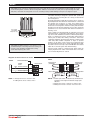
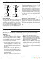
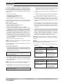
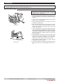
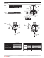
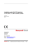
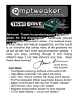
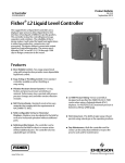
AlarmScout A15
Installation, operation & service manual
AlarmScout A15
UNPACKING
Top mounting displacer units are shipped from the factory with the displacer and
cable assembly removed from the head assembly and packed separately in the
same container.
If reshipping to another location, displacer assembly must again be removed
from the control to prevent damage.
Unpack the instrument carefully. Make sure all components have been removed
from the foam protection. Inspect all components for damage. Report any concealed damage to the carrier within 24 hours. Check the contents of the carton/crates against the packing slip and report any discrepancies to Honeywell
Enraf. Check the nameplate model number to be sure it agrees with the packing
slip and purchase order. Check and record the serial number for future reference
when ordering parts.
0038
0344
HANDLING
Nameplate:
- part number
- serial n°
These units are in compliance with:
1. Directive 94/9/EC for equipment or protective system intended for use in potentially explosive atmospheres. EC-type examination certificate number ISSeP09ATEX024X - flameproof enclosure.
2. The PED Directive 97/23/EC (pressure equipment directive). Safety accessories per category IV module H1.
The threaded connection link and stem protruding from the head assembly are extremely fragile. DO NOT handle or place
control in a position so that any amount of force is placed on the stem. Proper operation of the control requires that the stem
is not damaged or bent.
Displacer spring and stem are fragile. DO NOT drop displacers into tank. Hand feed cable into position to avoid bending stem.
MOUNTING
Adjust the displacer on the displacer cable for the desired
switch actuating level (instruction tag attached to cable).
Screw displacer cable fitting to threaded connection link
protruding from the underside of control.
Floating roof
High level
Be sure there are no tubes, rods, or other obstacles in the
tank or vessel to interfere with the operation of the displacer. No guides into the tank are necessary unless liquid turbulence is excessive, in which case a "guided pipe" or tube
should be at least 25 mm larger than the displacer diameter, open at the bottom end and with several vent holes
located above the maximum high level of the liquid.
Check installation of pipe or tube to be certain it is plumb.
CAUTION: Before attaching the control to tank or
vessel, using a level, check to see that tank
mounting flange is within 3° of horizontal in all
directions. Proper operation of the control depends
on the switch housing being plumb.
For floating roof top applications, the displacer switch may
be mounted via flange or threaded mounting on a bracket,
catwalk, etc. or through an opening in an outer dome roof.
Ensure that there are no obstacles to interfere with the
operation of the displacers or weights and that there is a
level surface on the roof beneath the displacer/weight.
CAUTION: Operation of all buoyancy type level
devices should be done in such a way as to minimize the action of dynamic forces on the float or
displacer sensing element. Good practice for
reducing the likelihood of damage to the control is
to equalize pressure across the device slowly.
2
Instruction & installation manual
AlarmScout A15
Part No.: 4417903_Rev.0
WIRING
CAUTION: Level controls are shipped from the factory with the enclosing tube tightened and the middle set screw,
on the housing base, locked to the enclosing tube. Failure to loosen the set screw prior to repositioning the cable
entry may cause the enclosing tube to loosen, resulting in the possible leakage of the process liquid or vapor.
Cover locking
screw (ATEX
flameproof only)
Screw
Screw
Set Screw
CAUTION: DO NOT attempt to unscrew the cover
of ATEX flameproof housings before loosening the
locking screw. ALWAYS retighten the locking
screw after replacing the cover.
The switch housing is designed to provide 360° positioning
of cable entry by loosening the set screw(s) located under
the housing base.
On high temperature applications [above 120 °C (250 °F)]
high temperature wire should be used between control and
first junction box located in a cooler area. Supply wires
(conductors) are brought into the switch housing, wrapped
around the enclosing tube under the baffle plate and then
brought up to the proper terminals. Excess wire should be
positioned so as not to interfere with switch mechanism or
housing cover.
Some controls are furnished with an explosion proof (cast)
switch housing or a vapor tight (gasketed) type. These housings are used in hazardous locations or when liquid temperature is so low that excessive condensation and frosting of
switch parts is likely. After wiring connections have been
completed, explosion proof housings must be "sealed" at the
cable entry with suitable compound or "dope" to prevent
entrance of air. Check cover to base fit on explosion proof
and vapor tight housings to be certain gasketed joint is tight.
A positive seal is necessary to prevent infiltration of moisture
laden air or corrosive gases into switch housing.
Connect power supply to control and test switch action by
varying liquid level. If switch mechanism fails to function,
check vertical alignment of control.
Diagrams of internal electrical circuits
SPDT
DPDT
Switch identification
Line
Load
Outside
circuit
A
B
Close on low level
1
4
Common
2
5
Close on high level 3
6
Load
NOTE: 1. Rising level closes contacts 5 & 6.
2. Falling level closes contacts 4 & 5.
Part No.: 4417903_Rev.0
Internal circuit
(left switch)
Internal circuit
4
1
5
2
6
3
Close on high level Load
Internal circuit
(right switch)
Load
Close on high level
Common
Common
Close on
low level
Load
Load
Close on
low level
NOTE: 1. Double pole action is obtained by simultaneous
operation of the right and left side single pole
switches.
2. Rising level closes contacts 5 & 6 and 2 & 3.
3. Falling level closes contacts 4 & 5 and 1 & 2.
Line
AlarmScout A15
Line
Instruction & installation manual
3
SET UP AND FUNCTIONS
Operating cycle
4
1
2
3
2
5
3
1
1
2
3
4
2
5
A spring is loaded with a weighted displacer which is
heavier than the liquid. Immersion of the displacers caused
by rising liquid level imparts buoyancy forces on the displacer allowing the spring to compress. The attraction
sleeve attached to the spring, moves upward into the
field of a permanent magnet . The movement of the magnet toward the sleeve causes the switch to actuate. A
non-magnetic barrier tube provides a static pressure
boundary between the switch mechanism and the displacer assembly. As the liquid level falls, the displacer lowers,
causing the spring to extend, and moving the attraction
sleeve out of the magnetic field of the switch mechanism.
This allows the switch to again change position and to
break or make.
3
1
Switch position on rising level
Floating roof detection
Switch position on falling level
Operating cycle – Proof-er control option
The purpose of the Proof-er is to check the operation of a
displacer control without having to raise the level in the
tank. This is accomplished by pulling downward on the
Proof-er cable. This causes the spring loaded lever arm to
lift the switch actuator, simulating a high or high–high level
condition. When the cable is released, the Proof-er returns
the actuator to its original position resuming normal operation.
The spring is loaded with a displacer weight suspended
from a stainless steel cable. As the floating roof rises, the
weight is lifted by the roof allowing the spring to compress,
the attraction sleeve to move upward into the field of the
switch magnet and the switch to actuate. As the roof lowers, the weight again hangs free causing the spring to
extend, the sleeve to move downward and the switch to
reset. The displacers are usually fabricated from ductile
metals, such as brass, to prevent sparking when the displacer makes contact with the roof.
MAINTENANCE
Preventive maintenance
If the following sections on "What to do" and "what to avoid" are observed, your level control will operate reliably.
WHAT TO DO
1. Keep control clean
Be sure the switch housing cover is always in place on the
control. This cover is designed to keep dust and dirt from
interfering with switch mechanism operation. In addition, it
protects against damaging moisture and acts as a safety
feature by keeping bare wires and terminals from being
exposed. Should the housing cover become damaged or
misplaced, order a replacement immediately.
2. Inspect switch mechanisms, terminals and connections regularly
– Dry contacts switches should be inspected for excessive wear on actuating lever or misalignment of adjustment screw at point of contact between screw and lever.
Such conditions can cause false switch actuating levels.
Adjust switch mechanism to compensate (if possible) or
replace switch.
– DO NOT operate your control with defective or
maladusted switch mechanisms.
– Level controls may sometimes be exposed to excessive
heat or moisture. Under such conditions, insulation on
electrical wires may become brittle, eventually breaking
or peeling away. The resulting "bare" wires can cause
short circuits. Check wiring carefully and replace at first
sign of brittle insulation.
– Vibration may sometimes cause terminal screws to
work loose. Check all terminal connections to be certain
that screws are tight.
4
Instruction & installation manual
WHAT TO AVOID
1. NEVER leave switch housing cover of the control longer
than necessary to make routine inspections.
2. NEVER use lubricants on pivots of switch mechanisms.
A sufficient amount of lubricant has been applied at the
factory to insure a lifetime of service. Further oiling is
unnecessary and will only tend to attract dust and dirt
which can interfere with mechanism operation.
3. NEVER attempt to make adjustments or replace switches without reading instructions carefully. Certain adjustments provided for in level controls should not be
attempted in the field. When in doubt, consult the factory or your local representative.
4. NEVER attempt to readjust magnetic attraction sleeves
which are factory set. Tampering may cause failure of
control while in service even though manual operation
actuates switches.
AlarmScout A15
Part No.: 4417903_Rev.0
MAINTENANCE
Troubleshooting
a. Disconnect wiring from supply side of switch mechanism(s) and remove electrical conduit or operating
medium line connections to switch housing.
Usually the first indication of improper operation is failure of
the controlled equipment to function, i.e, pump will not start
(or stop), signal lamps fail to light, etc. When these symptoms occur, whether at time of installation or during routine
service thereafter, check the following potential external
causes first.
–
–
–
–
–
Fuses may be blown.
Reset button(s) may need resetting.
Power switch may be open.
Controlled equipment may be faulty.
Wiring leading to control may be defective.
If a thorough inspection of these possible conditions fails to
locate the trouble, proceed next to a check of the control's
switch mechanism.
Check switch mechanism
1. Disconnect power to the level control.
2. Remove switch housing cover.
3. Disconnect power wiring from switch assembly.
4. Swing magnet assembly in and out by hand to check
carefully for any sign of binding. Assembly should
require minimal force to move it through its full swing.
5. If binding exists, magnet may be rubbing enclosing tube.
If magnet is rubbing, loosen magnet clamp screw and
shift magnet position. Retighten magnet clamp screw.
6. If switch magnet assembly swings freely and mechanism still fails to actuate, check installation of control to
be certain it is within the specified three degrees of vertical. (Use spirit level on side of enclosing tube in two
places, 90° apart.)
7. Check switch continuity with ohmmeter.
NOTE: As a matter of good practice, spare switches should
be kept on hand at all times.
If switch mechanism is operating satisfactorily, proceed to
check sensing unit.
Test controlʼs performance
1. Reconnect power supply and carefully actuate switch
mechanism manually, using a non-conductive tool on
electrical switch mechanism, to dertermine whether controlled equipment will operate.
b. Relieve pressure from tank or vessel and allow unit to
cool.
c. Remove switch housing assembly by loosening set
screws located at the bottom of the housing base.
4. With switch housing assembly removed, inspect attraction sleeve and inside of enclosing tube for excessive
corrosion or solids buildup which could restrict movement, preventing sleeve from reaching field of switch
magnet.
5. Inspect displacer stem and spring assembly to assure it
is not damaged. If stem or spring is bent or otherwise
damaged, movement of the attraction sleeve inside the
e-tube will be restricted, preventing proper function of
the control.
6. If trouble is still not located, proceed to remove the entire
sensing unit from the tank or vessel by unbolting head
flange or unscrewing mounting bushing. Inspect displacer assembly and all internal parts for any signs of
damage. Check assembly for binding by supporting
head flange or mounting bushing over the edge of a
bench and move displacer assembly by hand.
NOTE: When in doubt about the condition or performance
of a control, contact the factory or consult your local representative.
Proof-er
If the Proof-er is not functioning properly, listed below are
potential problems and corrective action.
1. Proof-er does not return to the down position after it is
activated.
CAUSE
Defective return spring.
Buildup between the
shaft and housing
restricting movement.
Handle stops are not
adjusted properly.
CAUTION: With electrical power on, care should be
taken to avoid contact with switch leads and connections at terminal block.
2. If controlled equipment responds to manual actuation
test, trouble may be located in level sensing portion of
the control (displacers, spring, stem, and magnetic
attracting sleeve).
Clean Proof-er to
remove buildup.
Adjust handle stop
screws in or out to allow
the handle to move to
the proper position.
2. Switch will not trip when Proof-er is activated.
NOTE: Check first to be certain liquid is entering tank or
vessel. A valve may be closed or pipe line plugged.
3. With liquid in tank or vessel, proceed to check level
sensing action by removing switch housing assembly.
CAUTION: Be certain that electrical circuit(s) through
control is deactivated.
Part No.: 4417903_Rev.0
REMEDY
Replace spring.
AlarmScout A15
CAUSE
The switch mechanism
is defective and not the
Proof-er.
Handle stops are not
adjusted properly.
REMEDY
Check switch mechanism.
Adjust handle stop
screws in or out to allow
the handle to move to
the proper position.
Instruction & installation manual
5
SPARE PARTS
CAUTION: DO NOT attempt to unscrew the cover of ATEX flameproof housings before loosening the locking screw.
ALWAYS retighten the locking screw after replacing the cover.
Replacing switch assembly
CAUTION: Before attempting to remove a switch
mechanism, be certain that electrical circuit(s)
through control is deactivated.
1. Disconnect wiring from supply side of terminal block on
switch mechanism. Note and record lead wire terminal
locations.
2. Loosen screw in split mounting clamp until mechanism
slides freely on enclosing tube.
3. Remove small round head screw securing lower switch
mechanism to baffle plate.
Mounting screw
4. Slide switch mechanism off of enclosing tube. If mechanism is to be reused, ensure that it is placed on a clean
surface, free of metallic particles that may be attracted
to the switch magnet.
5. Loosen mounting screw so that switch frame will fit over
e-tube. Install switch mechanism by sliding it over the
enclosing tube. Slide mechanism down until the bottom
of the frame and terminal block are resting on the baffle
plate. The baffle plate should be resting on the hub of
the housing base.
Baffle plate screw
Baffle plate screw
6
Instruction & installation manual
6. Install and tighten baffle plate screw so that the switch
mechanism may not be separated from the baffle plate.
Tighten the mechanism mounting screw so that the
mechanism is firmly clamped to the enclosing tube.
7. Swing magnet assembly in and out by hand, checking
carefully for any signs of binding.
8. Reattached supply-side wiring to the terminal block and
check switch function by varying liquid level in the vessel.
AlarmScout A15
Part No.: 4417903_Rev.0
SPARE PARTS
Spare parts
Partn°:
Digit in partn°:
1 2 3 4
5 6 7 8
4
5
9 10 11
1
Lockwasher
ground screw
Baffle plate
2
Locking screw for ATEX
flameproof housing
Serial n°:
See nameplate, always provide complete partn° and
serial n° when ordering spares.
Housing base
External grounding
screw for ATEX housing
3
Set screw
4
Set screw
7
6
6
7
6
6
6
8
8
(1) Housing cover
(2) "O"-ring
(3) "O"-ring
(4) Enclosing tube
(6) E-tube gasket
(7) Proof-er cable kit
(8) Displacer + cable kit
Part No.: 4417903_Rev.0
Spare part
consult factory
012-2201-253
012-2201-116
consult factory
012-1301-002
consult factory
consult factory
AlarmScout A15
Digit 9
B
C
U
X
(5) Switch assembly
Digit 10 + 11
Spare part
H9 or KQ
089-7401-104
J9 or NQ
089-7401-122
H9 or KQ
089-7401-110
J9 or NQ
089-7401-125
H9 or KQ
189-9109-901
J9 or NQ
189-9111-901
H9 or KQ
089-7412-004
J9 or NQ
089-7412-005
Instruction & installation manual
7
Fo r M o r e I n f or m a t i on
To learn more about Honeywell Enraf’s
solutions, contact your Honeywell Enraf
account manager or visit
www.honeywellenraf.com.
A m er i c as
Honeywell Enraf Americas, Inc.
2000 Northfield Ct.
Roswell, GA 30076
USA
Phone: +1 770 475 1900
Email: [email protected]
Eur ope , M iddle East and Af r ica
Honeywell Enraf
Delftechpark 39
2628 XJ Delft
The Netherlands
Phone: +31 (0)15 2701 100
Email: [email protected]
Asi a Pac ifi
fic
c
Honeywell Pte Ltd.
17 Changi Business Park Central 1
Singapore 486073
Phone: +65 6355 2828
Email: [email protected]
4417903_Rev.0
APRIL 2012
© 2011 Honeywell International Inc.