1
JAN. 31,1980
WRS-2
Power
MRS-2
switch
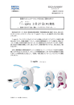
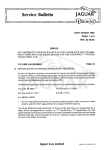
DISASSEMBLY
SDG5P-5O1-1 (001-215)
100V
•INPUTS AND OUTPU1S
•SPECIFICATIONS
•LFO (Low Frequency Oscillator)
•KEYBOARD
WAVEFORM ( ^
(37 keys, 3 octaves, F-F)
fD
^
M: -6dBm, L:
^ ,
LFO RATE (0.1 Hz - more than 80Hz)
•VCO (VOLTAGE CONTROLLED
OSCILLATOR) (X2)
•DELAY/BEND SECTION
VCO RANGE (16', 8', 4')
WAVEFORM (/I, HI ^ fill)
PULSE WIDTH (50%, 40%, 20%, 10%)
•VCF (VOLTAGE CONTROLLED
HPF CUTOFF (40Hz - 5kHz)
LPF CUTOFF (20Hz - 20kHz)
•ENVELOPE GENERATOR (1 EACH
FOR VCF, VCA)
HEADPHONE jack (stero; 8n)
MASTER TUNING (greater than ± 1
220/240V
Button No.9 (016-009)
VCO
: approx2v/8va
VCF
: approx 1v/8va
VCA : approx 1v/2.2cU
"-(2)
Removal Screws
VCO-2 "A" TUNING (greatr than ± 1
CV OUT jack (1v/ 8 va!
octave)
GATE OUT jack ( + 10v)
VCO-2 "B" TUNING (greater than ±1
CVINjack(1v/8va)
octave)
GATE IN jack (greater tran + 10v)
PORTAMENTO (0 - 3sec)
SUSTAIN LEVEL (0 - 100%)
RELEASE TIME (14ms - 10sec)
SDG5P-5O2 (001-217)
VCO: approx2v/8va
•TUNING
•CONTROLLER SECTION
ATTACK TIME (0.6ms - 3sec)
DECAY TIME (14ms - 10sec)
117V
HEADPHONE LEVEL sector (H, M, L)
with BEND SENSITIVITY control at "10"
semitone)
FILTER)
- 12dBn)
BEND CONTROL IN jacl;
DELAY TIME (0- 10sec)
SD&5P-5O1-2 (001-216)
OUTPUT LEVEL selecto(H: OdBm,
(1)
Front Upper panel
(2)
Bender Control Block
(3)
Keyboard
Blind H52
(O65HO52)
(2)
End
block No.l7A
(O91-O17A)
(3)
•GENERAL
VCO
: greater than + 1 octave
VCF
: greater than + 2 octaves
VCA
: greater than +6dB, - 12dB)
Power consumption:
20w
Overall size: 765(w)x40;<d)x 162(h) mm
(resonance pitch)
Weight:
Accessories:
14kg
2.5m connection cord
Holder No.203B (O64-2O3B)
Holder No.205B (O64-2O5B)
Knob No.56
Panel No.265D (O72-265D)
(016-056)
Knob No.33
Knob No,57
Side Panel No.70B
(064-204B)
Side Pane:. N0.69B .
(O83-069B)
i
(016-057)
(083-070B)
Holder No.204B
(016-033)
Foot (collar) BU480 CA25
black (111-024)
Felt No.27
(101-027)
Knobs No.56
I(016-056)
f
Holder No.232A
Keyboard assy
SK-132G (004-011)
Buttons
No.9
No.85
No.89
I Roland
(064-232A)
Bender Board
Black
White
Blue
(016-009)
No. 86
(016-089)
No. 88
1016-085)
No. 87
Red
Green
Yellow
[016-086)
[016-087)
[016-088)
Printed in Japan
OP-107 (149-107)
Key CV Board CV-3
(152-003)
Nylon Rivet
NRP-335 4pcs
(122-001)
Bender
Unit PB-4
(029-022)
Panel No.268B
MRS-2
JAN. 31,1980
Control Board A
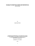
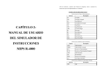
KEYBOARD PARTS
Control Board P
Control Board B
OP-108 (149-108)
OP-109 (149-109)
Control Board (
Power Supply Board
OP-111 (149-111)
PS-52
(146-052) 100V
VCO-9 ContDl Board
OP-134 (14-134)
PS-53
KEY SPRING
r
GUIDE BUSHING
(0684)16)
(146-053)
117V
VCO-9 (32-009)
PS-54
KEY ASSEMBLY
Module Boarc
220/240V
OP-105 (14-105)
A
B
C
0
E
C
(IVORY)
(IVORY)
(IVORY)
(IVORY)
(IVORY)
(IVORY)
(1064)17)
(1084)18)
(1064)19)
(1084)20)
(1064)21)
(1084)22)
SIDE ANGLE
CHASSIS
CONNECTOR
ACTUATOR RUBBER
(107052)
F (IVORYH106415)
G (IV0RYH1Q6416)
(146-054)
KEY HOLDER
5P (064.053)
7P (0644)54)
IP (064.056)
2145-3C
(0104)29)
ACTUATOR
(102003)
/
CONTACT LEAF
(071001)
I
SPACER
(073-051)
SHARP (BLACK)
(1064)23)
BUS> BAR HOLDER
(0644)57)
Module Control
Board )P-106
(149-L06)
LEVEL
LEVEI- Switch
Switch
Board I
Board II
OP-112 (149-112)
OP-113 (149-113)
Mother Board OP-104
(149-104)
When ordering PCB, suffix an alphabetical letter to the part numbe:
refferring to the Parts List and PCB Wiring Layout.
Hinge No.3 (115-003)
Jack HLJO1O2-O1-O4O
6 pea
(009-025)
Music Rack Hder
No.219B (O64-19B)
11111
Roland
Chassis No.242E
(061-242E)
Switch
V
SSBO2332
(001-271)
Jack HLJ-235-(-O7O
Stereo (001-0-)
CONTACT LEAF
HOLDER
6P (064-051)
7P (064-052)
PRINTED CIRCUIT BOARD
RESISTOR
JAN. 31,1980
DESCRIPTION
Punclon of
CIRCUIT DESCRIPTION
Hothc Board
1. Operational
Principle:
In the conventional synthesizer, the circuits
(VCO, VCP, VCA, etc.) are directly controlled
What is Compu-Phonic S'
from the control panel.
(Features of Compu-Phonic
In the compu-phonic synthesizer,
it is the
computer that comes in between and provides
control voltages suitable to those VCO,
VCA,
Control
Synth. Circuit
Panel
VCO-VCP-VCA
2.
EM GEN,
VCP,
etc.
In t"3 Mother Board
inclled
are
the
micrsomputer 8048012 id its
perpjral
circuits,
(ref: to the General
Bloc Diagram when
readig the following)
Hardware:
- "
Compu-Phonic Synthesizer is composed of the
Conventional Synthesizer
"Synthesizer Control Circuits" with ;iPD8048
I
"
as its central point and the "synthesizer
circuits" which are fully controlled by
Control
Compu
Panel
ter
Synth.
Circuit
VCO-VCP-VCA
voltage.
Mother Board Block Diagram
f
START
J
Compu-phonic Synthesizer
SW,
Switch Reading
Control Pane]
(Programmable
Section)
2-1.
Control Section:
Sliders and switches on the
control panel are now not for
Synthesizer
Panel Data Reading
A/D Conversion
Modules
(3) Storing these A/D converted data of the POTs and SWs into
memory for use afterward upon retrieval.
(4) Converting back again these digital data
into analog voltage (D/A conversion) to send
Memory
Buttons
(This data reading
to complete them all).
(VCO-VCP-VCA)
Preset
Preset
(2) Converting the Analog signals obtanined from Sliders and
Switches of the Programmable Section on the Control Panel,
is repeated 16 divided times
£
■Data
Buttons
etc.
into 8-bit digital data (A/D conversion).
Timbre
setting
Computer
Compu-Memory
- Switches and Sliders -
(1) Scanning of all the switches on the Control Panle such as
Memory Write SW, Manual SW, Compu-Memory SW, Pre-Set Selection
them out into Synthesizer Modules.
the production of the synthe
All these functions stated above are perform
sizer control
ed under the control of 8048-012.
signals directly,
such as the production of the
time constants, ON/OPP switch
ing,
etc.
They now serve
only
to letting the computer know
-Functions of 8048-012-
I CV & GATE
Keyboard
Key-assign
Diode .Matrix
Computer
-1-
(Tone color setting controller)
These operations of 8048-012 are shown in the
of their positions or the
states as
they are
put on the
JP-4 only-
Control Panel.
* In JP-4,
Assign Mode
Switch
(KCV and GATE
generation)
2-2.
flow chart. The 8048-012 repeats such flow
the Poly-
chart cycle.
Phonic Synthesizer,
The following numbers refer to those in flow
8048 is adopted on
its key-assigner
circuits too.
D/A Conversion
Analog Data Hold
Digital Data Hold
is turned on,
8048-012
data of the positions it reads of Memory Write Switch,
Selection Switch.
Synthesizer Circuits:
2. The 8048-012 takes in at first the voltage data of one
Such parameters as the time
constant,
power
starts its reading and puts into memory the
Manual Switch, Compu-Memory Selection Switch and Preset
Voltage Controlled
ON/OFP switching,
or their signal levels,
chart .
1. When the
etc.
have so far been produced on
These are,
circuits,
however, now produced by the computer's internal
controlled, programed and/or given by the
contained transconductance amps or analog switches,
However, the circuit and
etc.
into 6-bit digital data. At the same time, it reads out
the "Switch Position"
computer, with self-
sliders and
obtain directly of such.
of the "Slider pots" on the Control Panel and converts it
and the synthesizer circuits are under fully voltage
the control panel there are
switches to
-<"l6th ?
etc.
function themselves of VCO, VCP, VCA
of the synthesizer's main circuits are just as the same
as before with those on the conventional synthesizer.
8048-012
( JP-4,
Flow Chart
PROMARS )
on the Control Panel and converts it,
too, into 2-bit digital data. The two data thus obtained
are combined to make a total 8-bit data. These are held
there for a while.
JAN. 41, l»0U
DESCRIPTION
3. If the MANUAL Switch was OFF at step
1,
7. The 8048 divides the 8-bit data (data in step
the program proceeds to step 4, or if ON, to
2 or data retrieved in step 5) into two formats:
7. During this process, the data obtained in
2-bit switch data and 6-bit
step 2
The 6-bit data then proceeds to D/A conversion.
is maintained.
Those two signals of analog converted voltage
4. When the Memory Write Switch was OFF at
step It the program goes to step 5, if ON, to
to 6. The step 2 data is still maintained.
accesses to either
Access Memory) when
and of switches
RAM (Random
a switch in Compu-Memory
it goes back to step 1.
If all are completed
If not,
to 2.
It then reads
-Switch Reading-
The 8048-012 scans the matrix made of the diodes
switch depressed, the data to give control
and switches on the Control Board F to find out
to the Synthesizer Modules.
which switch is depressed among those of WRITE
through MEMORY PROTECT.
data held in step 2 to RAM, selecting the
address over there which is corresponding to
the switch position on the
COMPU-MEMORY SWs.
consists of 16 pots and 14 switches,
these 16 pots
produe 16 different kinds of analog voltage varying
betweft OV to 5V.
The 14 SWs,
on the other hand,
respectively.
from 8048-012
given by
bits
The 16 analog voltages that
Control (9),(10),
(ll)
come Ji parallel to each other are re-arranged thru
the aalog multiplexer(MPX) IC5, IC6 4051, to be put
Multiplexer
on a ingle line in time sequence.
These3utputs of the MPX go into the A/D con-
verte (will be described later) to become
IC5,IC6,4O51 can be regarded as the same to
1. Diode-Switch Matrix
6-bitdata of 16 kinds.
a rotary switch provided with one more
On the Control Board F,Switches(each accompanying
The 1 binary data of the switches are also re-
on itself as shown above.
arraned into 2 groups of 7 kinds (total 14) with
Port 1 of 8048 outputs both the Address
diode) are grouped into 4 blocks consisting of
2 to 8 switches.
8 bits
IC8
IC7
LS175
Of th( Control Panel,the section named"PROGRAMMABLE"
+5V o]OV,
out from the address corresponding to the
6. Based on the data in step 1, it writes the
H, All _
and ccnverts them into digital data of 16 bytes.
produe binary digital data of "H" or "L",
was pushed in, or ROM (Read Only Memory) when
one of Preset Switches was in.
The 8(48-012 reads the patching on the Control Panel
( lbyte = 8 bits)
all 16 cycles to read out all data divided into
16 at the previous stage.
+5V
The PROGRAMMABLE SECTION
are fed to the Module Boards.
8. The 8048 checks to see whether it completed
5. Based on the data being held in step 2, the
8048-012
slider data.
- Reading of CONTROL PANEL -
LS175
switch
These blocks are then
each roup entering each respective MPX IC3,IC4
signal (Control A, B,C, Pins 9, 10, 11),
which also serves as switch for 4051 itself
connected through the data bus to DBO,
wherethey are made to 2-bit data and be output
DB3, DB4, DB6 on 8048-012. The blocks
fron here in time sequence as above. These 6-
for INPUT/OUTPUT Address data, and Chip
Enable Signal (INH, Pin 6).
are also routed through to the pins of
bit ad 2-bit data are combined to become an
P20-P27 on Port 2 of 8048-012.
8-bitdata.
They are then making a matrix, (refer to
firstnade on the Control Panel are become to be
the Circuit Diagram, Control Board F)
repreented by all digital data of 16 bytes in
2.
That is to say,
that,
(There are 4 of 4051. Pins 9, 10, 11 of all
the patching
four are connected through the same lines)
all. refer to Memory Map on page 13)
To Scan the Switches
The 8048-012 outputs "L" onto DBO alone
nlR
DB7
- D/A and A/D Conversion -
and "H" on all other DB1-DB7.
DBO
They are out on the data bus and latched
g()48-OI2 K-
on IC7,
P20
IC8,
74LS175 by the pulses from
1. D/A Converter
INJT
—o
OUTPUT
pin ALE (Address Latch Enable) to be out
"R-2R type".
The converter here is only making use of higher
Next, 8048-012 reads the Port 2 (P20-P27).
significant
6
If it finds here that the P20 alone
the least significant 2 bits unused.
put onto D0-D6 of TSET.
while all otheres on "H",
Scanning /
The D/A Converter used on the Mother Board is the one called
"L"
2. A/D Converter
The above process is repeated to go over
all of DBO to DB7,
but four of them are
The A/D Converter on the Mother Board is referred to
connected to switches.
D/A Converter
as " Successive Approximation Type Converter"
MEMORY WRITE Switch (SW1) is so wired that
To proceed on with conversion,
Input
lection switch is ON with the PROTECTION
switch (SW21) being depressed at the same
(see circuit diagram, CONTROL BOARD F)
bit,
then down to those lesser significant bits.
IC9,
IC10 serve as an inverter, making the input to
follow negative logic.
therefore,
Latch timing
1
The output is +5V maximum,
when it receives the input LLLLLLXX,
or
OV minimum when HHHHHHXX.
U
(XX are for those least significant bits that are
DBO
IC8048-
012
DB Data Latch Timing
8048-012 starts
deciding the data at first for the most significant
time,
Memory
Address
which
make use of the D/A converter and a comparator.
Analog
it is only enabled when Compu-Memory se
Switch Scanning Signal Flows
leaving
then it can
know of that the SW1 is on.
signals
4 bits
bits among those of 8 bits given here,
T1
T1
Comparator
A/D Converter
Output
made nil.)
CIRCUIT
JAN. 31,1980
DESCRIPTION
(Numbers 1-6 below in this section refer to
1' 21 3
those at top in figure right)
The 8048-012 tries at
"L",
first putting DB7 to
thus making the digital data at first
to LHHHHHXX,
tentatively.
These are latched
on LS175 by the pulse from ALE pin,
out onto the D/A converter.
hand,
On the
Signals
on
input
analog
Comparator
Input pins
p
CEl
45
CEl
;
then
* t
one
8048-012 reads the output level of the
comparator,IC13 311,
It makes
through Tl pin.
comparison between these
WRITE TO EXTERNAL DATA MEMORY
Comparator
two,
of
5101 READ/WRITE CYCLE
the A/D input and of D/A converted output
to LHHHHHXX (= 2.5V).
Decision on
If the A/D input is
"L"
to be as shown in figure ( a straight line
a little over 2.5V),
the comparator
— {JEBRATION of CONTROL SIGNALS to MODULE BOARD(S) —
finds
D/A Converter
input data
that the D/A converted output LHHHHHXX(2.5V)
is less than that of A/D input.
The cotrol data that were A/D converted to
It is to
instruct 8048 to decide that the "L"
The8048-012 reads
the input data into 16 at
the control signals from
8048-012 (IC31,32,pins 6,
aremade to analog voltage thru
er than the A/D input as in step 2 on
Input:Data Comparison
D//converter and are put
It makes the output of the com
9,10,11). They are held at
on a
TL082,IC22 through IC29 to
sirle line in time sequence and
parator 311 turn to "H". That means,that
Bach time,
"L"
the D/A output approaches
successively
nearest to the A/D input voltage. And finaly, when
so it must be reset back to
8048 completes them all for DB7 to DB2 for bits,
H again. Tne same process continues through
the lesser significant bits,
DMPX here is to separate
suc-
6 Us (DB7 to DB2) among them
comaring data
With this data,the D/A output becomes high
is too large,
these
cesively from RAM or ROM.Upper
to output LLHHHHXX.
8048 has now to decide that DB6 in
out
digtal data of 16 bytes
X:
irrelevant
Now, 8048 turns to DB6 in putting here
figure.
signals before they are sent to the Module Board(s).
pre
is to remain on DB7 hereafter.
again "L" tentatively,
kinds of analog voltages and 14 kinds of binary
8-bit .igital data are re-converted to 16
viously put on tentative base can be firm
so that "L"
READ FROM EXTERNAL DATA MEMORY
Output
be sent
aresent to 16-output analog de-
out to the Module
Controller and the Module
mu3iplexer,DMPX IC31,IC32,4O51.
■■■ Control Signal
it
has decided the data on the nearest approximation to
as on step 3-
15
Board.
DMPX & HOLD circuits
be equal to that of input of the A/D converter.
6 on figure.
2.The lower 2 bits data,
DB1, DBO are fed in
time
sequence
the input pin of each respective address data latch 4099,
IC12.
- Memory -
to
IC11,
The two 4099s latch them in separate 7 groups under the
control signals from 8048-012 (to pins 4,
5, 6, 7).
The outputs of 14 kinds go into the level shift circuit following
Here provided on this Compu-Phonic Synthesizer
8048-012 outputs from Port 1 the address data to
are "CMOS RAM",
turn the Chip Enable (CEl) to "L" on 5101.
Then, 8048-012 outputs
the pulses from ALE pin
IC2,
5101 for memory of the
tone color (timbre) data to be used on
Compu-
Memory and ROM which resides in 8048-012 for
ase on PRESET mode.
to make LS175 (IC7,
13
4099 where they are
■• Control Signal
e*l Shift
IC8) latch the data and
Circuits
8048-012
3. Of the 14, those of VCO-WAVE 1, /and LPO-WAVE 1, 0 are fed to
outputs onto DBO to DB3 the data to be written.
ACCESS to 5101
These data are then written onto 5101 by turning
W to "Ln, and are read by 8048 through DBO to
DB4 when 55 is "L". The digital data on the
Control panel are
8 bits format.
However, when made access to 5101,
divided into 2 by 8048-012.
they are
(Because 5101 han
the Wave form selector,
WR T sig
R timing
signal
(inputlT
RD
ALE
IC1
__
Address Latch Enable
Chip Enable signal
8048-012
Port
Port 1
D
go into Transpose
Range
8XH
Select Decoder,
Subtractor where the contents of the 2-bit
turned to "L"
Range 0
(inputK
Refer to Table
tfor what conversion is meant
(output)
on this transpose.
Transpose by the Subtractor
In effect,
it is to go down by 1 octave
tection of its memory. The NiCd battery will be
on VCO range as shown by
fully recharged for more
arrows.
than 48 hours.
The memory on 5101 are also protected for an
codei
IC20 and LPO
data of RAN3E 1, p are converted when the Transpose Input is
5101 is backed up by the NiCd battery for pro
WR DB7-4 DB3-0
IC19,
IC33, IC34 to receive each respective decoding. VC0-RAN3E 1, 0
Range 1
dles 4-bit quantities.)
CD
levels each suitable for the
define the memory address upon 5101. While the
memory address being defined by LS175,
8 bits
shifted into
purpose to each. (Section surroundingQ3-Q14.)
hour by the electrolytic capacitor (lOOOmfd
6.3V)
just
in case when the battery is removed
for replacement or other.
IC2O-4070
transpose
IC21-4001
Titispose
Subtractor
Thus,
the Switch con
trol signals in 14 kinds be
come to control the Module
Boards after passing through
these circuits as above.
CIRUIT
DESRIPTION
- OTHERS -
Reset Circuit
2. CF and its Peripherals
, +5V
The circuit is to protect 8048-012 from running pro
gram inadvertently. When RESET pin 4 is turned to "I1,1
it makes 8048-012 to reset back to the
This
initial state.
is also connected to 8048-011 through the
mon line.
JAN. 31,1980
VCIhere is not much different from those on
IC18 is the electronic potentiometer to control
theconventional synthesizer.
the depth of the cutoff frequency modulation.
hi|-pass filter.
com
power off
(8048-011, JP-4 only)
filers.
IC11
is the
IC12-IC15 are the low-pass
IC17 is the circuit for setting
foithe low-pass filters.
Reset Circuit
3.
Included here are VCO,
VCF,
VCA and 2 ENV GENERATORS.
Geirators,
ICla(pin 1,2 and 3) makes the
D, , R.
vetfd on the Module Con-
current is then compared at
trcBoard,
the Comparator IC5b(pin 5,6,
the A,D and R
corols are
flowing
to be achieved
G
Sustain
by>ntrolling the number
in from pin 6 of IC4 thru
of ilses
R118.
Not that,
The output of the comparator
IC5b is made to control the
frequency produced from IC4,
VCO OUT
the
qivider
IC6
PC4O24
VCO has to make the oscilla
n n n n r
n n.
-O<0-
nnnni
O let
Rectangular
out
-O . (D
it always keeps the differ
these pulses here
GATE
8i£ from screen on the
1/4
1/8
ence at zero in values be
oscloscope if the pulse
intvals were extended a
lite long.
IC2i8 the flip-flop which inverts itself on
is a pulse arrival,
arring at the attack level.
discharge, accordingly.
IC24 is the gate
seating the pulse for each of A, D, and
^
feCfKB EBMfi
byie timing of the flip flop.
PV converter
T=constant
TC-
4Q52
log IC2.
IC25
4001
it ly easily be lost of
1/16
tion in such frequency that
Control pufses
Level
in a given time.
ar€)f so narrow width that
1/2
VCO generator oscillation
current I-exp from the anti-
out
beg voltage-pulse con-
This antilog
pin 6 of IC4 and the antilog
Since the signals
araow in the pulse form,
which outputs antilog current
tween the current Ig from
IC21b
th*ime or the level of A,
the antilog transistor IC2
however,
for
cinits to voltage-control
KCV
mixed and sends them out onto
Here,
each
The are basically the
keyboard key voltage KCV
Gate IC.
one
VC&nd VCA.
vibrato voltage VCO CONT and
7) with the current
Envelope Generator
The are two Envelope
VCO and its Peripherals
from pin 9.
IC19 (pins 5,6,7) is the cutoff frequency con
trol mixer. Q8 and Q9 are the antilog current
generation circuit.
- MODULE BOARDS -
1.
Q
R
IC22 is the
ansg switch which turns on only when there
thus making C20 to charge-
On such charge/discharge, envelopes are devel
oped. The envelopes from C20 are fed through
buffer IC21 to obtaine low output impedance.
N\N\I
Sawtooth
The VCO outputs are in the
out
pulse form of the constant
width converted by the one
- MODULE CONTROLLER -
shot multivibrator 103(555).
It is therefore necessary to
double the number of pulses if the antilog current
IC5a generates sawtooth waveform synchro
is doubled.
nized to that of the selected frequency.
Mode Controller Board is to control those on
Mode Board as
follows:
The Module Controller performs these functions
The amplitude of the sawtooth waveform is
0 modulation
by converting the control signals fed from the
Mother Board or those fed from the Bender
an additional voltage onto VCO to make it regain
kept constant by choosing either of R18-
F modulation
Board into such signals to suit for controlling
the balance. These are the process how to output
R24 by the multiplexer IC7 regardless of
A modulation
the modules.
the frequency which is antilog-proportional to the
any change made at
neration of the clock signals to control
Here also included are the Noise Generator and
input voltage.
On PROMARS,
V GEN.
LPO Delay Circuit.
IC5b watches this to keep the balance
at this pin 6. And,
if losing the balance,
it sends
The pulse output here is of so nar
row width as yet.
it is necessary therefore to
provide further wave
conversion.
IC6 is a frequency divider.
IC7 is a multiplexer
to make selection from those divided frequency,
2nd VCO.
the tone feet.
it has a VCO 9 Board for its
This Board is in effect
just as
the same that the VCO section is only taken
out from the Module Board stated herein.
toff frequency of HPP
lse width modulation of VCO
JAN. 31,1980
CIRCUIT
DESCRIPTION
H
H
H
H
fl?SIER B0ARD TIMING DIAGRAM In MANUAL MODE
H
(SLIDER/SWITCH READ/HOLD, A/D & D/A
CONVERSIONS, MPX and DMPX)
5
o
o
p
Figure felow is part of CP9, 11, 12, 17 and 13 at the left showing functions
and tim-igs of A/D, D/A conversions and the Switch reading.
Studing)/A conversion theory on the Mother Board by observing the converter
I
8s"
S3 O
3 P
o
£5
O
O
fa &
M ft
TTTT
output uveform is very helpful in understanding the operation of microcomputer
CO
8048-01;
M
O
TT
pin 6
)
3. In Miual Mode, at CP13, final of A/D and D/A outputs are equal in level.
MPX output
(IC3
1. The omputer 8048-012 reads Sliders set positions through A/D /conversion.
2. The omputer reads,between A/D and D/A conversions, Panel switches status.
This leans that Panel Data are fed into Synthesizer Modules as they are.
Howeir, in other modes, A/D and D/A show different values because they
Pin 3)
are it of relation to each other, D/A converter transforms digital data
from he memory.
4. Durii D/A conversion, sliders data being D/A converted from 6-bit format
MPX output
(IC4
pin 3)
and itch data from 2-bit format are held (latched) and output to the
syntsizer modules.
All sliders on the
PROGRAMMABLE
set at "0" except VCP ATTACK (at
are
"3"
)
MAX
MPX output (IC5,
pin 3)
flid?r
uuuuumm
Enable pulse
innnnnnn pmc
to
IC6
Switch
X^ Reading
This !slider
positions
"0"
(pin 6)
D/A Converter
output
(IC14 Pin 1)
D/A output
H
T1TTTTTI
MEnable pulse IC5,IC6
(Sir read pulse)
CP11,CP12
MPnable pulse IC3,IC4
(Sch read pulse)
§
CQ
DMBnable pulse IC31,IQ32
CO
S3 ° | | 8 S
O
g
&
Ad3sable Data Latch
Gapulse IC11,IC12
(S^rs and Switches
DHold pulse)
CP16 or CP17
Slider
Reading
Switch
/Reading
VCP ATTACK
LEVEL is set
!at :"
uinu
DESCRIPTION
JAN.31,1980
PIN
FUNCTION
NO.
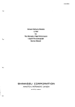
Signals Plow Diagram on the Mother Board
ifPanel
[Switches Data
Sliders
Push
and
Switches
Tanel
Scanning
Sliders
Switches Data
RAM
during RAM
address
Data
14 Sws,
address
I/O address
Indicate
Data
Plows from the Control Panel.
4051:
IC3-IC6,
4099:
1011,
5101:
IC2
IC31-IC32
IC12
CFT
Data
Bus
select
Port 1
Will be output to the Synthesizer Modules only
55
in Manual Mode.
WR
ALB
Digital
i-Switch Scan
L Read ing Data
8048-012
Logical Symbol
Show Data to/from the Memories in Compu-Memory
and Preset Modes.
Inputs for internal Clock Oscillator
Will not be output to the Synthesizer Modules in
Reset pulse input
Manual Mode.
Comparator output signal input during A/D conversion
Memory read timing signal output
Analog
Memory/Write timing signal output
DB Data latch pulse output
Common lines for the data from the Control Panel
and
(Top v iew)
the Memories.
UPD8O48
The ;iPD8048 is an 8-bit
computer fabricated on
silicon
Tl
14 SWs
26
VCA-A
PW/PWM
to
LFO
to
'27
16 Pots
Range 1
WR
25
24
to Synthesizer Modules
single
The 8048 contains a
IK x 8 ROM program memory,
27 I/O
lines, an 8-bit timer/counter and
clock circuits.
Used in the Compu-Phonic Synthe
17
sizers are ^08048-012 andjuPD-
16
8048-011 (JP-4 only) versions in
15
which programs and data dedicated
14
to the Compu-Phonics are stored
13
12
11
10
r<m;
23
22
21
2u
8
chip.
parallel
a
in the program memories.
T
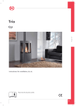
MttS-2
JAM.31,1980
( VOUIKE )
o
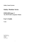
-9 Control Board^.
Control Board-F
ki
Ir-il
o
l
Control
Board-A
0P-1Q9 PCB #Mf2
PCBI237
OP-1O8
ppri34 pcb #468 (master
K2
— I
Control Board-C
Control
OP-110
WB #329
OP-111
PCB £328
Ltt)
h—ii irr=
o
I
o
2ao
I Power Supply Board
100V
PS-52
PCB *527
117V
PS-53
PCB #27
ZkOV
PS-$k
PCB *527
61
E4
E3
S2
I — ^
TjA* Mother Bcari
OP-104
PCB #364
["
VCO-9 Board
VCO-9—PCB
Module Board OP-105-PCB
Module Control Board
L-0P-106-PCB #235
<
W
rf-T
L
SJ
1— * LLtlU 11—-10
I
It 'I
Bender Board
o
[
OP-107
PCB
M.IT
Mft
o
o
Board
CV-3
PCB
rrUl
HI
T*
MS
iKteaconnection diagram
Bl
.
'*■ fl B2
I
SEMICONDUCTOR
SN741SI74
7-STAOB BINARY COUNTER
TC4024P
Hgj* o-tvfre MJMi*
JAN. 31,1980
DIAGRAMS
741S175
QUAOROPLE O-TYPE FLIP-FLOP
TC40S1BP
TC4082BP
etoc
TROTH TABLB
SIKGLB 8-CHAKNKL MULTIPLBXKR/DBMULTIPLBXBR
DIFPBRBNTIAL 4-CHAKNBL MULTIPLBXBft/DEMULTIPLBXBR
Y-CHO m|
CI.BAR
CH4 w
Y-CR8
Y^OOMMON |i I
Y-0H3 i
n
Y-CH1
©
m|
INHIBIT <
Ml
-em
I*
:-oomwon
OH?
its
:-cho
GHS a.|
C-CH3
lot VDD
Iff 0H8
It? OH I
CH6 Ml
:-ona
ib oho
INHIBIT o|
o
CM
Ife CH3
A
o
ib b
OND ©I
OND ol
I© B
l« o
LOGIC DIAGRAM
*i
fta
74LS00
k3
JIACH PM^P
L • low i««ti Utaetfy tttta)
X • lrral«v«m
CLOW G
TROTH TABLB
t - trtntitlon from low to hl^ ttwcd
Qo - the tovtri of Q before the IntfteMed itw
input conditions weie established.
T - '173. 'LSI 78. and *Sf 7S only
TC4O69
u
13
)
a
u
10
BA662
TC4049P
o
o
LM311
i
OmMh-UmIMmi*
T 0 40 0 0
>uPD5101C-E
MmiOM
WNtONFIQURATION
6R0OT0118
LOGIC SYMBOL
T 04 00 IP
QUAD 8-INPUT P081T1VB NOR OATB
TC4025P
TRIPLE 3-INPUT POSITIVE NOR OATB
3*569
ohd
sC
mwra-
QUAD RICLUSIVB-OR GATt
Doo
3 m.
tt
BLOOf DIAGRAM
' 0N0
Doe,
TL082,11072
Do,,
1t
TC401IP
3
«
6
TRUTH TABLE
0
ovb
TC4016
TC4O9OBP
QUAD
BILATRHAL
TC4O90IP
TRPTH TABU
SWITCH
BLOCK DIAGRAM
00OTROL
RB8BT
1HPOTB
AOERBS8 INPUTS
W.D18
8-BIT
OUTPUTS
Ql
0.8
44
QUAD 2-INPUT
POSITIVE HAND GATE
Connection Diagram (Top View)
iTCH
ounQ
BLOCK DIAGRAM
R
30UT/IN u[
TRUTH TABL&
]• sout/m
TC4013P
DUAL D-TYPB FLIP-FLOP
OMB
L
L
D04
^_
•
t a
*»
ft ;
DOH'T
0ARB
®0©
DATA
IKBttf
o
o
OCWVOfSTOHiNOO
r
v.
c
d auvoe loaiNoo
i i i i i tt
C
c
OUVO911301439
c
C
C
0
8 CRJVOS1OU1N00
vauvoaioaiNOO
BOARD
MODULE CONTROL BOARD
MODULE BOARD
TOD-2
A-TUB3
B-TUNE
HASTES TUNE
tb SENDER BOARD
«Q«R£CaiBQL BOARD
1SUBOSC
vco
&EHERATD&
VCA
IU
BIVELOPE
COMTft)LCUXK
WAVE
1SUBOSC
VCAEMV
HfF
R>RH
VCO
VCA
LPP
SQIODR
RELEASE Q]
VCAXW
DECAY, OKI
VCFENV.
VCRENV
WELEA5EOK
YCFBNV
DECAY UK
VCA
VCF
5EH.'
16EH.
Jil
U-TJJ
X.
olo
3
A24
to BENDER
MOTHERBOARD
to BEHOCR BoAtO
LTO
WAVE
Rfth
U
u
i
PORTO-
Control
MEMT
Voltdge
GEN.
37KBT
KtY BOARO
1'i!^'rrS""--'^*:Ji-*Vi\t»^jKt^'i!;-:-,ii1. ,'■-'' "■
■
1
KETCV80ARD
HOLD
CVIN
'^^ " .
11
Ill
»-* C gz]
f
TL_
CMOS Multiplexer
enable pulse
MOTHER B0/«0 A$s>
PCB O52-364
Must
L
m
(v
-
O- OB
I*
>X>
4fl
4nt
^
^
[
«o
Control BoedLF
ttll
to Control BoorcL F
]
]
Control
2SA1OIS-Y
Crop view)
\
Ci
"
i
i
l
r
r-r-r
I
I
I
I
I
I
I
I
I
I
I
I
I
I
I I I
IT
I
i
I
.
I
!
I
I
i—r-r—
I
I
I
I
I
I
I
I
I
I
I
I
I
I I I
i
i i i I
LL
n
OATH
.
I
I
i i
o >
i
K.CV
?, 2 io i
a d
SttjEcr
§
Oq
111 in in
OO
III
1
AI7-AW
r
icaa
•lexer
to BENDER
Board
tN2)
No.8 No.9
A
Rectangular
Sawtooth
Inverted
Sawtooth
LFO
CPU RESET
12
MOTHER BOARD
A
A
A
>nnfifinT
J_
All Sliders on the PROGRAMMABLE
MEMORY
section are set at "0"
6-bit
Data
1 or 2-bit
Data
CP
16
Latches
Control
P&nel
CP
i
Microcomputer
17
Figures in TP colum in the table to Immediate ri
at top of the other tables refer to test points
layout below. The following applies.
o
1. For sliders; voltage Will vary within the rang
as the designated slider is being moved.
2. For switches; -the output will be a logical 0 (
o
(OV,+15V),(-15V,+5V),(OVf+5V)f
MOTHER BOARD OP-104B
(Etch mask 052-364 B)
o
o
G
O
IMPORTANT
^ replacing the Mother board,
depending
on
th
check both the exi
and the new repiacement board for existence or ab
and Q16.
If different, see page 19 lor modificat
NOISE
VCP KEY FOLLOW
LFO WAVEFORM
SUB
VCO WAVEFORM
PULSE WIDTH
CLe to immediate right and figures
'er to test points shown in the PCB
•plies.
VCP POLARITY
iry within the range of OV to +5V
being moved.
LL be a logical 0 (low)
or 1 (high);
0, depending on the lever position.
check both the existing board
PW/PWM
VCO RANGE
for existance or absence of Q15
?ei9
for modification.
componenvs
on foil
C48,
side:
C49
Connector
A6, A10,
A14,
JlL8, A23
(connections to
Power Supply-
Board El)
MOTHER BOARD
13
BENDER BOARD OP-107B (149-107B)
View from foil side
Switch SUP-12 (001-225)
Switc
0P-107
CON1
SHO.,2,3
HC-25K-18K (001-238)
O
UC-42M-18K (001-237)
VR1-
VKL0RB10C2MAK2O
(028-756)
LEVEL SW BOARDS
I PHONES
II OUTPUT
OP-112A
OP-113A
f!49-i12A)
(I49-113A)
<PCB 052-443A)
rSWl
CONTROL
B
SQPR-2412P (001-228)
SW2
SSB-022 (001-182)
3W3
BHM-1034-K15
(001-234)
XBCM2M-18K (001-237)
SV6
SRM-1O45-EL5
(001-224)
All Pots
BVA-TL7C16B54 (029-355)
VCO-9 CONTROL BOARC
©P-134A t!49-134A)
Wiewftom foil side
SW
SSB-02332
(001-271)
0P-134
CONTROL BOARD A-a
OP-109A (149-109A)
View from foil
VRs
EVH-LWAD25B15 (030-951)
SWs
LBC-23M-18K
CONTROL A
(001-238)
0P-109
VR3
BVA-V17C16C26 (029-370)
IRA
EVA-V23C16B54 (029-426)
SW3
LBC-42-18K
COSTRdL
C
SW1
SQIR-2412P (001-228)
SW2
IBC-42M-18K (001-257)
All Pots
EVA-TL7C16B54 (029-355)
(001-237)
Ji
JULY 31,1979
CONTROL BOARD F-c
5046-O5A
OP-108C 049-1080) (EtehmMk0522S7C)
K-l
XL-225)
Switch
SUF-J2 (001-250)
CONTROL BOARD B-d
all diodes:
jumpers on 052-237B
Switch SUF-12 (001-225)
1S1588
C.
c
OP-110D (149-110D)
H 1
ROL BOARD
5O46-O9A
View from foil side
5O46-O9A
o
H 2
OP-111B (149-111B)
)-134A)
TO7
1B8
TO9
TRIO
o
foil«kle
-2412P (001-228)
t2M-18K (001-237)
5B54 (029-355)
I 2
9D46-O1OA
14
CONTROL BOARD
CONTROL BOARD C-b
Mew fromfoi side
CONTROL BOARD
o
Control Board B **J
Control Board C
PCB # B2?
PCB
#928
o
OP-134
FvCO-9 Control
PCB «468
VRI
o
V*2
*3
MODULE CONTROL BOARP
CB2]
O—
-i$v
OP-113
vco-2
VC0-2
TOflE
OP-112
ON-OFF
o
io NOTHBt BOARG
CA293
tO MOOULt CONT.
IB I]
o
I I I I; I I/I
BEKDER BOARD
OP-107
Control BoArat F
PCB # 237
o
o
1
I
_,
I
_
I
m
■
II
m
*
"i
i
i
i
i
i
i
i
I
r~i
i
i
□
10] IC2
}iP<558
Ql
2SC1815Y
Q2 2SA1O15Y
Dl- 1S1588
LPO Modulation
JAN. 31,1980
VCO-9A (152-009A)
(PCB 052-439A)
C31, C33
33/16V
on the foil side
o
C-l
o
-M-
••- IS 1588
— 2SAIOIS Y
— 2SCI8ISY
--25K3OA d
— Polystyrene Film
m —- CftB ^FX MFR
• — MFVR
O
JAN.31,1980
KCV BOARD
o
o
CV-3A (152003A) (PC8052440A)
(152-003B) (PCB 0524408)
S/N up to 850729
8/N 860730 and higher
~ 181555
-fc -2SA1015
023-
<--2SCi815
o
o
IMPROVEilENTS on CV-3
o
PORTAMENTO(with Serial number 850370 -- CV-3B)
With Circuit i in th# figurt right♦ 0 ohargaa oloa©
io CV IN relaiively fast* but will not charge up to
the exact CV j! for a while (theoretically, indefi
PORTAMENTO
nitely) .
TIME
Circuit B
74IC
■•Ban
o
o
i>(7
v-E
Potted lines ..........
3>L
and paranthesises
SJoUT
with numbers show
|]OPPSBT
original CV-3A
HULL
Connection Diagram
(Top View)
circuit arrange.
One of the diodes keeps IC2 outpit
0.6 V higher (in the case figure inmediately right)-or lower than
CV IN
ov out
A3*
CT
PORTAMENT
J
IN and C10 charging (discharging)
rate is speeded up along curve-B.
Once voltage across C10 reaches tie
CV IN, feedback resistor 3.3K will
CV IN
IC2
TIME
T
TC10
IC1
Improvements on CV-3
2.
cont'd
Shifting TRIO. GEN.
KEY
CV
- CV-3A only
Module control op-106c (149-1060
CV Oil
(PCB 052-235C)
I TRIO. GEN|
This relieves the following:
When keys on MRS-2 are
played
in
KEY GATE
GATE
IT
legato with the CV and GATE IN/OUT
SYNTH
tones corresponding to the subsequent
MODULE
PORTAMENTO
<■
keys can fade away along with the
first key1a envelope decay(a remarka
being blocked with CSQ-lOO circuits,
does not exist at GATE IN, failling
I KEY
1
V
CV
CV IN
vn GATE
0V-3A
ble example is Preset PIANO).
This is because Gate-retrigger pulse,
Moving the A, D or R
sliders from bottom to
jacks being connected to a CSQ-lOO,
JAN.31,1980
original
top
D1-D6
V
will increase the
frequency
o
Cathodes
\
by
approximately 1000.
<JUCa(TU4O4y) Outputs
vfl CV 00?
1
KEY GATE
vfl GATE (IT
to re-set envelope generator for in
dividual keying
that follows to the
first keying in sequence.
After modification, MRS-2 has no de
SYNTH
IPORTAMENTOJ-M-
MODULE
GATE :
trimental effects on sequencers other
variations
than CSQ-lOO.
The modification was conducted on
MRS-2 with serial number 840630;
o
frit CV IN
modification on PCB
besides, pj?oduet@ bearing the
following numbers have been
modified before shipment.
830568-830599
810260-810279
830533-830534
830547-830548
830552.830554
Rll shifted from
the component sid
830600-830617
830528-830529
,.*JtUu*.
83O54O-83O545
83O556-83O557
the foil
side
830619.830621
bridge
foil scraped off
Roland
O
052-#440A
n
JAN.3i.1M0
MODULE
CONTROL
o
o
MODULE CONTROL BOAR© Asffj OP-106
PCS
OS2- ?3S
ENV CLK Generator
o
o
n
TC4069UBP
ONLY
Selected for
Noise Generator
to MOTHER BOARD A21
oontrol signal
O
TC12 Pin 1
NOISE Q24 Emitter
JAN.31,1980
MODULE BOftRO
PC8
For the drcuits -(^ (2) {£)
Ass'.?
O52-3l4E*ee right below.
OSZ-3I4D
IC4 TC4O69UBP
of
O
MC1455P
'kMTIC PMKAOI
CAM Alt
(Top VMwl
IMC14MP1 anlyl
o
VGA ENVELOPS
WAVE FORM SRKTOR
Capacitors on the
o
foil side:(0P-104D)
C33, C34, C35 and
lOOp,
lOCOp
con
nect to IC1.
o
to MOTHER BOARD
-— Polydiyrene RJm Capocttor
ccCce)
ccCe)
to MOTHER BOARD
A8,12,16,20
▲ — CKB»APy MFR
^
NOTE:
RI53
A7,11,15,19
to MOTHER BOARD A6, 10,
14.
18
to MOTHER BOARD A5,9, 13, 17
2
&
luesowwcel
• --MF VR
MODULE
BOARD
0P-105D compatible
o
OP-1O5E
20
MRS-2
JAN.31,1980
MODULE BOARD
o
F>OWfeR SUPPLY BOARD
BA662
Besides BA662 -A and -B, there are factory selected marked with various
colors. Although they are interchangeable,however,because of electrical
characteristic differences,use only in complete set of the same color.
For non-selected: BA662A is a good replacement for BA662B while BA662B
cannot replace for BA662A.
OP-105D (149-105D)
(PCB 052-314D)
o
bn6loRIS!
PS-52P(146-052F) 100V
PS-53F(146-O53F) 117V
PS-54F(146-O54F) 220/240V
(PCB 052-327F)
PUSES
OP-105E (149-105E)
(PCB 0524146)
Q1,Q2
2SA1O15-Y
Q3
2SB596-Y or 2SB434-0
Q4
2SD880-GR or 2SD234-Y
o
Dl
D2-D4
O5Z5
1N4OO3
or
or
RD5.6E
1N4002
o
POWER,TRANSFORM3RS
o
o
022-104DM
1OOV
O22-1O4CC
117V
022-104CD
22O/24OV
Bl,
B2
W02
or
KBPO2 or
1D4B1
**
, S.
21
JAN.31,1980
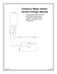
ADJUSTMENT
1 kEY CV and WIDTH
Because certain circuits of PROMARS are voltage controlled, Power Supply Board,
TUNE
WIDTH
PS-52/53/54 is the first to be checked and adjusted. Also repairing or replacing
PS-** Board forces readjustment of some associated PCBs, CV-3, OP-104, VCO-9 and
OP-105.
KEY CV BOARD
Replacing a PCB other than Power Supply Board involves readjustment of its own.
OP-134/-
CONTROL BOARD F OP-108
VCO-9
FO
Connect digital voltmeter
to provide 2.00+2mV.
3. Check octave keys for errors:
052-328
052-442
OP-112
Lt~y?g=?
POWER
02 - 3.00±3mV
i U=O WAVEFORM
LEVEL SWITCH BOARD
OP-113
A2 C3
2. Hold down Cl key and adjust P-2
CV OUTPUT jack.
OP-111
I
C2
C2V =ciV + 1.00V+3mV.
to the hot terminal on
CONTROL BOARD C
PI
1. While depressing Cl and C2 keys
alternately, adjust P-3 so that
!
. CONTROL BOAB
052-468
Cl
o
03 = 4.00i3mV
MODULE BOARD
TDP-105 052-314
SUPPLY BOARD
OR9-
1*8-52/53/5
7
/
©
OP-104
052-364
o
MODULE CONTROL BOARD
OP-106
052-235
1
MOTHER BOARD
BOARD
I
I
1
1
1
1
1
1
1
■
1
Confaect oscilloscope to TP-4 on
Mother Board OP-104Isee next page). .
Numbers, ® , ® , [5] > «*o. in above figure show adjusting trimmer potentiometers
1. Adjust P-4 for slope straightness,
and are independent of designations in individual circuit diagram.
In this adjustment, trimmer pots are abbreviated as MP-xxM.
1. DC VOLTAGE (-16 Volt)
POWER SUPPLY BOARD
PS -52,-53, -54
Allow at least five minutes for warmup.
1. Connect a digital voltmeter to TP-1.
2. Adjust P-l for -15.0+l0mV.
TP-1
good
4.
ltd RATE
Identicalto
3. LFO WAVEFORM
♦ 5V
-
»
I
I
I
I
I
|
1
O
3. Check other voltages, they must be
+5.Q±25OmV
and
+15.O£75OmV.
Oonneot eoope to TP-5 on OP-104.
r" ^:=:_ 2
*J
n
MRS-2
JAN.31,1980
. VCO WAVEFORM (Pulse width 50%)
S. VCO FREQUENCY ind WIDTH
o
•tar: yirfJ,
JJBEfHtfflBEfflBff
II M II ^
LV-1 I
o
I
I
1
—'
i
1
o
□::
f©at Point -
Switch to A or B
VCO-9 Board.
c
t
i
i
i
i
i
i
i
i
i
i
i
305I
fP-3 on OP-1O4
Connect and set instruments as above.
and disconnect
OP-105
Set P-8's respectively
VCO-1 signal
VCO-9
for 5O?5 duty ratio with
(see section 5)
Cl key holding down.
during VCO-9
A2 key
to OP-io4
i
at A or S
5096
before adjusting
TP-3
\\\
adjustment.
7.
VCF FREQUENCY and WIDTH
MODUlfc BOARD OP-105
1.While depressing A2 key, Adjust P-7 for 1:2 Lissajous figure.
2.While depressing AO key, adjust P-6 for 2:1 Lissajous figure.
AO key
o
VCO-9
To disconnect VOO-1 signal paths
Pull the housing off the PCB.
istics of this VCP,
OP-105
right pin only<,
o
NOTE: Due to the digital control character
nn, vco-9
Reverse it and plug in the
if CUTOFF FREQ knob is
moved steadily and slowly,
the resonating
Set VCO-2 TUNE switch to A-TUNB or B-TUNE.
VCF will produce frequencies in a series of
Adjust P-6 and P-7 on VCO-9 Board following the steps in OP-105.
steps.
mm
(9)
If CUTOFF FREQ is
CUTOFF
set at a
point
©xaeily b©tw©©n two ©f th©§© ©t©psf th© r©VCO-9
MODULE BOARD
OP-105
MODULE CON/B
sulting frequency will be unstable
jumps up and down between
as
it
these two steps.
The knob must be set at a point near
20H2-—~S
"5"
where VCF output frequency locks positively on one frequency or the other.
OP-106
Test Point -
TP-3 on OP-1O4
1. While depreaaing Fl and F2 keys alter
nately, adjust P-ll on OP-105 to display
two figures of 2:1 period.
o
Reset KEY FOLLOW at "0".
2. Adjust P-12 on OP-15 for 880Hz.
o
(by displaying Lissajous figure,etc.)
MOTIH5R BOARD
Of-104
3.
Cheek F1,F2 keys for dtviations in step 1.
23
JAN. 31,1980
8.
11. VCA BALANCE
VC* RESONANCE
V'"m
V
T
■::
Test Point -
I *
'
"I J.-.JrfSr1.—.i.
T
u::. ^
rri'Tn tit
t i t n
"»'
Ifffif
I
1111
mi
■
I
I
I
:: □::
u:r
W4
TP-3 on OP-104
1. While depressing a key, adjust P-10 on OP-105 so
13 12 11
\
sine with RESONANCE set at "8".
F"
'
i, »•! « ... «
1
T
T '
'
- — •
' 1
!
TP-3 on OP-104
1. While modulating the VCA with BEND MOD lever,
adjust P-14 on OP-105 to minimize click
Trimmerpot
that VCF just begings' oscillation.
Approx. 800mVpp
Test Point -
WTViVr
sound.
10.9
/4
1P-105
good
wrong
o
UJUUUU U UUU U
9.
mm
11 VCA LfeVEL
VCF ENVELOPE BALANCE
foe^^
,r""i
-,..-
o
'
I
Test Point -
TP-3 on OP-104
Test Point -
1. While depressing down C2 key adjust P-15 on OP-105 for
TP-3 on OP-104
1. Adjust P-13 on OP-105 so that moving
I
■
i
i
!
i
:
■ n
7
ill
1.2Vpp
_ \
LFO VCO MODULATION
ENVELOPE MOD between "0" and "10"
produces no frequenoy change.
i
J
wrone '
~\
r
^> -IT
GO
-
-
"
-
"-
1
•Sf
10.
VCF ENVELOPE MODULATION DEPTH
mmo
Test Point -
Test Point -;
-1
UJ J.L
Hiii m
TP-3 on OP-104
1-^-*.
1
+
JJ
j»
ceo
OP-106
TP-10 on OP-106
Connect scope ground to G-3 on OP-104
□-
oo
1. Set P-20 on OP-106 for 150mVpp +10%.
150mVp-p
26
P-20
16
o
O
JAN.31,1980
MRS-2
14. LFO VCF MODULATION
17.
o
Test
o
VC^ ENVELOPE DECAY
lo
(see section 20)
f
HI
□::
□::
i
1.
i
i
i
i
i
i
i
i
i
Grounding Point Ground 3(0-3) on 0P-104
i n
i
Set P-19 on OP-106 for 600mVpp.
Test Point -
15.
TP-11 on OP-106
Grounding Point -
LFO VCA MODULATION
G-3 on 0P-1O4
1. Adjust P-21 on OP-106 so that frequency
.
lowers to 1/10 of its initial value
r"".~l
key ON
in
4 sec after depressing C2 key.
o
control voltage
VCF ENVELOPE RELEASE
TgL'jgj
□::
Test Point-
o
'
I
i———
,■'■■■ I .*•.■»,"»,-■■■ l«..,'»7'-)i
I I I I rTTTTTTl I I I 1
□::
TP-11 on OP-106.
Ground Point-
~
„
r—i
G-3 on 0P-104
1. With C2 key held down, push BEND MOD extremely right and
set P-18 on OP-106 for 100$ modulation.
Grounding Point - G-3 on OP-104
1. Adjust P-22 on OP-106 so that frequency lowers
e
to 1/10 of its initial value in 4 sec after 02
o
key is released.
16.
The amplitude decreases as its frequency lowering.
VCP ENVELOPE ATTACK
Increase scope vertical sensitivity accordingly.
control
voltage
key release
VCA ENVELOPE ATTACK
Test Point -
TP-11 on OP-106
Ground Point - G-3
o
o
on OP-104
Attack Time is defined as the time from a
keying to a sudden frequency drop.
1. Depress C2 key and adjust P-23 on OP-106
So that Attack time becomes 3 sec.
ktr
14niAM4MM
4- ^
Test Point -
TP-11 on OP-106
Grounding Point -
G-3 on OP-104
off
See
20.
MRS-2
VCA ENVELOPE DECAY
22.
JAN.31,1980
HPP CUTOFF FREQUENCY
i
3BHEf1
□::. i
off
t rTrr\
i
i
i
i
i
i
i
i
Ml
r ■-"""•
LJ-LJ
i
off
V01CE
5 sec
Test Point -
o
TP-ll on OP-106
Grounding Point -
G-3 on OP-104
1. While pushing BEND MOD lever extremely left,
adjust P-17 on OP-106 so that
sdund ratio of STRING and VOICE becomes 1:1.1 in amplitude.
Test Point - TP-ll on OP-106
Grounding Point - G-3 on OP-104
1. Adjust P-24 on OP-106 so that amplitude decreases to 1/10
in 5 sec after pressing 02 key.
21.
23.
NOISE LEVEL
VCA ENVELOPE RELEASE
Test Point -
TP-9 on OP-106
Grounding Point -
G-3 on OP-104
o
1. Adjust P-16 on OP-106 for 5Vpp.
Teat ?ei»t -
Tf-11 an OP-106
o
Grounding Point - G-3 on OP-104
1. Adjust P-25 on OP-106 so that amplitude
n
decreases to 1/10 in 5 dec after releasing *y-r*1*a.g
C2 key.
26
r
JAN.31,1980
MRS-2
POTENTIOMETER
o
o
PARTS LIST
Slide
061-242B
Chassis (case) no.242B
072-265D
Panel (top)
072-268B
Panel (bender) no.268B
083-069B
Side Panel
no.69B
right
083-070B
Side Panel
no.70B
left
111-024
Foot (collar)
no.265D
Rotary
RNGE (SUB on/off)
001-182
SSB-022
001-205
SSB-023
001-271
SSB-02332
I3VEL
001-228
SQPR-2412P
I?0 WAVE,
PW
Rotary
no.24 black
BU480 CA25
001-224
SRM-1O43K15
(TOO WAVEFORM
115-003
Hinge no.3
001-234
SRM-1O34K15
VCO RANGE
064-219B
Music Rack Holder
no.219B
o
Keyboard Assy
O91-017A
Bndblock
O65H52
Blind
KNOB.
n
o
no.l7A
SK-132G
149-1O4B
right
149-1O5D
H52
BUTTON
or
0P-105D Module Boird (PCB O52-314D)
0P-105E
compatible with 0P-105D
149-106C
0P-106C Module Coitrol (PCB 052-235C)
149-107B
0P-107B Bender Board
149-108C
0P-108C Control B»ard F (PCB 052-237C)
(PCB O52-441B)
016-033
Knob no.33
016-056
Knob no.56
rotary small
149-109A
016-057
Knob no.57
rotary large
0P-109A Control Board A (PCB 052-442A)
016-009
lutten ne.f
149-11OD
blaak
OP-HOD Control Board B (PCB 052-239D)
Button no.$5
149-illB
016-085
white
OP-lllS Oontrel Board 0 (PCS 052-328B)
016-086
149-112A
Button no.86
red
0P-112A level SW ]!oard I (PCB O52-443A)
016-087
149-113A
Button no.87
0P-113A level SW ]loard II(PCB O52-443A)
green
016-088
Button no.88
149-134A
yellow
0P-134A VCO-9 Control Board (PCB 052-468A)
016-089
Button no.89
152-003B
blue
CV-3B
152-OO9A
VC0-9A VCO-2 Board (PCB O52-439A)
PS-52F Power Supply Board (PCB 052-327F)
slider
146-052F
SWITCH
146-053F
OOi-250
SUF-J2
interleek
001-225
SUF-12
MEMO/WRIT. M PROTCT
001-226
SUF-12A
HOLD
001-215
SDG5P-5O1-1
power 100V
001-216
SDO5P-501-2
117V
001-217
SDG5P-5O2
o
220/240V
lever
001-237
001-238
KCV Board
(PCB O52-44OB)
100V
Push
o
0P-104B Mother Boird (PCB O52-364B)
1
149-1O5E
IBC-42M-18K PW. NOISE, etc
IBC-23M-18K TUNE A/B, PORTA, etc
PS-53F Power Supply Board (PCB 052-327F)
117V
146-054F
PS-54F Power Supply Board (PCB O52-327F)
220/240V
O52H195A
LED Mounting Board
power switch
or
052-307
JACK
009-002
LJ-039-1-6 or
009-045
HLJ-0235-01-070
009-025
PB-4 Bender unit assy
028-756
VM10RB10C K20
2MA
028-762
VM10RB10C K20
50KB
028-992
EVHD0AK15
50KB BRILLIANCE
028-1109
EVHB8AK15
50KA VOLUME
028-1118
EVHB8AK15
50KB
030-951
EVHLWAD25B15
50KB A/B TUNE
Slide
PCB
004-011
029-022
HLJ-0102-m -r
el tereo
M. TUNE
-2
IC
022-104DN
Power transformer
100V
022-104C0
Power transformer
117V
022-104CD
Power transformer
O22HO94
Coil
220/240V
24M333
Diode
018-018
1N4OO3
018-059
1S1588
018-082
W-02
018-092
RD-5.1EB
rectifier bridge
zener
018-015
SDT-1000
019-022
GL-3AR1 LED power.memory
019-020
GL-3AR2 LED
thermistor
LPO,VCA
changeable, however,
due to character-
iitio di;f£©r©ne#, ua© the same 10
specified in the circuit diagram.
HOLDER
020-095
MC1455
O64H55
H55
020-051
MC14001
064-184
020-046
MC14011
064-185
020-083
MC14O16
No.184 (Module, Module Cont. VCO-9
No.185 (Module, Module Cont. VCO-9
064-186
020-076
MC14O24
No.186 (Module, Module Cont. VCO-9-Mother Board)
064-187
No.187 (Power Switoh)
020-093
MC14025
064-203
020-075
MC14O49
064-204
020-090
MC14O51
No.203 (Bender Panel-Bender Board)
No.204 (Bender, Panel-Bender Board)
064-205
020-091
MC14O52
No.205 (Bender Unit)
064-210
020-177
MC14O7O
No.210 (Bender; Panel-Bender Board)
064-219
020-178
MC14O99
No.219 (Music Rack-Panel)
064-226
020-084
TO4O69UBP
No.226 (End Block)
064-227
020-031
JJA723DC
No.227 (Side Panel)
064-231
020-106
ji»A7805DC
No.231 (Control Board-Panel)
064-232
020-108
UA7815U0
No.232 (Bender Panel-Keyboard)
064-233
020-097
uPC4558C
No.233 (Battery)
064-239
020-101
J1PC741C
No.239 (Mother Board-Chassis)
020-181
)lP05101C-E
064-249
No.249 (Push Switch)
064-230
020-032
UA726H0
No.230 (Control Board-Panel)
179-021
;aPD8048C-12
020-141
SN74tSl75N
020-054
1M311
020-100
TI082
020-039
DN819
020-160
BA662A
020-096
BA662B
non
BA662S factory se .ecied
only
when
right)
left)
CONNECTOR
010-177
PICD-9P-T1
010-178
PICD-9S-TL1 Module, Module cont, VCO-9 female
Mother Board
male
Wafer Terminal pin
Erect
Right Angle
010-182
5O45-O2A
010-183
2-pin
5O45-O3A
010-192
5O46-O2A
010-184
3-pin
5O45-O4A
010-193
5O46-O3A
010-185
4-pin
5O45-O5A
010-194
5O46-O4A
5-pin
010-195
5O46-O5A
For VCP, there are factory e elected.
BA662s painted in particular colors
010-186
aocording to the eleetrioal
5O45-O6A
010-187
5O45-O7A
6-pin
010-196
5O46-O6A
010-188
7-pin
5O45-O8A
010-197
5O46-O7A
010-189
8-pin
5O45-O9A
010-190
9-pin
010-199
5O45-1OA
5O46-O9A
10-pin
010-200
5O46-1OA
jharao-
teristics.
When replacing,use the BA662
in the
same color, and when ordering} idenote
Although some equivalent ICs are inter
JAN.31,1980
color as well as BA662S.
COVER
048-046
055*003
Heat Sink No.46
. Rechargeable Batt'
iry 4N-100AAS
065-065
No. S5
065-190
No.190
065-066
No.66
065-232
No.232
065-143
No.143