1
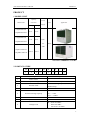
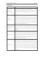
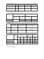
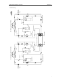
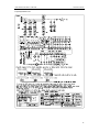
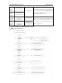
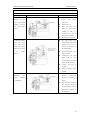
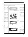
Air Cooled Scroll Chiller Service Manual (T1/R407C/50Hz) GREE ELECTRIC APPLIANCES INC. OF ZHUHAI CONTENTS PRODUCT.......................................................................................................................................2 1 MODELS LIST ....................................................................................................................2 2 NOMENCLATURE .............................................................................................................2 3 FUNCTION ..........................................................................................................................3 4 PRODUCT DATA ................................................................................................................4 4.1 Product Data at Rated Condition.................................................................................4 4.2 Operation Range..........................................................................................................5 4.3 Electric Data................................................................................................................5 5 PIPING DIAGRAM .............................................................................................................6 5.1 Cooling Only...............................................................................................................6 5.2 Heat Pump...................................................................................................................7 CONTROL ......................................................................................................................................9 1 OPERATION FLOWCHART ............................................................................................9 1.1 Cooling Operation.......................................................................................................9 1.2 Heating Operation .....................................................................................................10 2 MAIN LOGIC .................................................................................................................... 11 2.1 Cooling Mode............................................................................................................ 11 2.2 Heating Mode(Defrosting/ Auxiliary Electric Heater(E-heater)).........................12 2.3 Antifreezing Protection Control ................................................................................14 2.4 Control of 4-Way Valve.............................................................................................14 2.5 Control of Water Pump..............................................................................................14 3 WIRED REMOTE CONTROLLER................................................................................14 3.1 Function ....................................................................................................................14 3.2 Operation View .........................................................................................................14 3.3 Display View .............................................................................................................16 3.4 Menu Structure of Controller ....................................................................................17 3.5 Sketch map of DIP switch .........................................................................................18 INSTALLATION...........................................................................................................................20 1 BEFORE INSTALLATION ..............................................................................................20 2 INSTALLATION SITE......................................................................................................20 3 CAUTIONS FOR INSTALLATION ................................................................................20 4 MACHINE FOOTPRINT .................................................................................................20 5 DIMENSION DATA ..........................................................................................................22 6 INSTALLATION CLEARANCE DATA..........................................................................22 7 TYPICAL WATER PIPING DIAGRAM .........................................................................23 8 ANTIFREEZE ....................................................................................................................24 9 ELECTRIC WIRING WORK ..........................................................................................24 9.1 Wiring Principle ........................................................................................................24 9.2 Electric Wiring Design ..............................................................................................26 9.3 Wiring Diagram.........................................................................................................28 MAINTENANCE ..........................................................................................................................32 1 1 TROUBLE TABLE ............................................................................................................32 2 FLOW CHART OF TROUBLESHOOTING ..................................................................33 4 EXPLODED VIEWS AND PART LIST ..........................................................................46 2 GREE COMMERCIAL AIR CONDITIONER AIR COOLED SCROLL CHILLER PRODUCT 1 AIR COOLED SCROLL CHILLER PRODUCT PRODUCT 1 MODELS LIST Capacity Power Model Name Ref. (kW/Ton) Appearance Supply Cooling Heating 60/17 65/19 76/22 80/23 LSQWF65M/N-M LSQWRF65M/N-M LSQWF80M/N-M 400V- LSQWRF80M/N-M 3N- R407C 50Hz LSQWF130M/N-M 120/34 130/37 LSQWRF130M/N-M Note:1Ton =12000Btu/h = 3.517Kw 2 NOMENCLATURE LS QW R F 80 M 1 2 3 4 5 6 NO. Description 1 Water Chiller 2 Compressors Type 3 Function Code 4 Air Cooled 5 Nominal Cooling Capacity 6 Modular - 7 Development series number - 8 Voltage Code / N - 7 M 8 Options - Hermetic Scroll Compressors Omitted-Cooling Only R-Heat Pump - 65——60 kw 80——76kw 130——120kw M-380V-3N-50Hz、 400V-3N-50Hz、 380~415V- 3N-50Hz 2 AIR COOLED SCROLL CHILLER PRODUCT 3 FUNCTION Function Description Utilizing new scroll compressor technology, the chillers meet or exceed the High Efficiency performance requirements of ASHRAE 90.1.All system components are selected Full Load Operation for optimum performance, including the condenser coil areas and evaporator sizes. By using two compressors on each chiller, unloading characteristics and part load performance are outstanding. Integrated part load value (IPLV) is a part load Excellent Part performance indicator as outlined in ARI standard 550/590-1998.the IPLV rating Load Performance compress the performance of different chillers under identical conditions. When the IPLV is listed in EER(Energy Efficiency Ratio),a higher EER will indicate that the chiller’s overall performance is better. The chillers have a reputation for a compact design and small footprint. A small Compact Design With footprint can save installation costs by minimizing the size of the concrete Small Footprint mounting pad or reduces the amount of structural steel if the unit is mounted on the rooftop. The chillers are designed with quiet scroll compressors. Fans are selected for good performance and lower sound levels. The attention to detail with sound is Quiet Operation critical in the design. Small issues such as refrigerant piping, supports for piping, securing components to the structure are all important to making a quiet product. We proudly publish our sound performance. GREE has provided the latest technology in controlling the chillers. The new controller provides a “user friendly” environment for the operator. The control logic is designed to provide maximum efficiency, to help provide continuing Superior Controls operation in unusual operating conditions through proactive controls, and to provide a history of conditions to aid in problem resolutions. Perhaps the greatest benefit is the protocol for integrating with your building automation system(BAS) 3 AIR COOLED SCROLL CHILLER PRODUCT 4 PRODUCT DATA 4.1 Product Data at Rated Condition Cooling Only Models Nominal Capacity LSQWF__M/N-M 65 Heating 130 LSQWRF__M/N-M Heat Cooling 80 Pump 65 80 130 kW 60 76 120 Ton 17 22 34 kW 65 80 130 Ton 19 23 37 Power Cooling kW 22.6 28.7 45.3 Input Heating kW 21.7 26.7 43.3 Power Supply 400V-3N-50Hz Microcomputer Auto Control; Running Control Running Status Display; Abnormal Status Alarm High-Low Pressure Protection; Discharge Temp Protection; Motor Overload Protection; Anti-freeze Water Flow Protection; Low Water Flow Protection; Phase Sequence Protection; Safeties Compressor Overload Protection; Compressor Inset Protection; Presure Differential Protection; Compressor Type Hermetic Scroll Compressors Refrigerant Type Water m /h 10.3 13.1 20.6 Flow GPM 45.4 57.7 90.7 kPa 10 15 17.5 Pressure Drop Cooler R407C 3 Heat Exchanger Max. Pressure Shell and Tube Evaporator MPa 1 Water In/Out Pipe mm DN65 DN65 DN80 Diameter Heat Exchanger Condenser Fan Motor Power Input Finned Coil Type Condenser kW 1.15×2 1.15×2 0.75×4 Outline/ Width mm 2110/2190 2110/2190 2410/2490 Package Depth mm 1100/1180 1100/1180 1900/1980 Dimension Height mm 2140/2140 2140/2140 2240/2240 kg 940 1030 1670 kg 1034 1133 1837 Net Weights (Heat Pump) Operation Weights 4 AIR COOLED SCROLL CHILLER PRODUCT (Heat Pump) Net Weights (Cooling Only) Operation Weights (Cooling Only) kg 905 985 1565 kg 996 1084 1722 Notes: ① Nominal capacities are based on the follow conditions: ② Parameter refer to the nameplate; Water side Item Water flow Leaving Water Dry-bull temp. Wet-bull temp. m3/(h·kw) ℃/℉ ℃ ℃ 7/45 35/95 — 45/113 7/45 6/43 Cooling 0.172 Heating Air side 4.2 Operation Range Water side Item Cooling Heating Air side Leaving Water Temperature Difference Air on Condenser (℃/℉) of Water(℃/℉) (℃/℉) 5~15℃/ 2.5~6℃/ 18~48℃/ 41~59℉ 37~43℉ 64~119℉ 40~50℃/ 2.5~6℃/ -15~24℃/ 104~122℉ 37~43℉ 5~75℉ 4.3 Electric Data Rated Model Compressor Power Fan Motor MRC NRC each each 2 31 22.1 2 3N- 2 38 27.2 50Hz 2 54 41.4 Supply Qty. LSQW(R)F65M/N-M 400V- LSQW(R)F80M/N-M LSQW(R)F130M/N-M Qty. NRC Total MRC NRC 2.3 66.6 48.8 2 2.3 80.6 59 4 3 120 94.8 each Notes: MRC: Maximum running current (A) NRC: Nominal running current (A) 5 Thermal Expansion Valve Filter compressor Temperature Sensor compressor Temperature Sensor Pressure Switch Filter Thermal Expansion Valve Vapour Liquid Separato Temperature Sensor Pressure Switch Heat Exchanger with Axial Flow Fan Heat Exchanger with Shell and Tube Pressure Switch Vapour Liquid Separato Temperature Sensor Pressure Switch Heat Exchanger with Axial Flow Fan AIR COOLED SCROLL CHILLER PRODUCT 5 PIPING DIAGRAM 5.1 Cooling Only 6 Thermal Expansion Valve Liquid Tank Thermal Expansion Valve Filter Check Valve Check Valve compressor 4-way valve Water Inlet Water Outlet Temperature Sensor Vapour Liquid Separator Temperature Sensor Filter Thermal Expansion Valve Liquid Tank Check Valve Check Valve Heat Exchanger with Axial Flow Fan Pressure Switch compressor 4-way valve Heat Exchanger with Shell and Tube Pressure Switch Temperature Sensor Vapour Liquid Separator Temperature Sensor Heat Exchanger with Axial Flow Fan Thermal Expansion Valve AIR COOLED SCROLL CHILLER PRODUCT 5.2 Heat Pump 7 GREE COMMERCIAL AIR CONDITIONER AIR COOLED SCROLL CHILLER CONTROL 8 AIR COOLED SCROLL CHILLER CONTROL CONTROL 1 OPERATION FLOWCHART 1.1 Cooling Operation 9 AIR COOLED SCROLL CHILLER CONTROL 1.2 Heating Operation 10 AIR COOLED SCROLL CHILLER CONTROL 2 MAIN LOGIC 2.1 Cooling Mode In cooling mode, the four way valve is always off as long as the controller is energized and it hasn’t anything to do with the states of compressor and fan. Tout=T_Cout+ΔTXN+T Tin=T_Cin+ΔTXN Tout=T_Cout+ΔTXN+T Tin=T_Cin+ΔTXN (1)Control of compressor For the module n, N=n & 0x03,ΔT=0.5,T=0.3.Compressor 1 and 2 will start and stop in fixed time. Compressor 1: When Tin≥T_Cin+ΔT×N, compressor 1 is on. WhenTout≤T_Cout+ΔT×N, compressor 1 is off. Under other conditions, it keeps original. Compressor 2: When Tin≥T_Cin+ΔT×N+T, compressor 2 is on. When Tout≤T_Cout+ΔT×N+T, compressor 2 is off. Under other conditions, it keeps original. (2)Control of fan Dual-fan system If both of the compressors are off, fan A will be off. If either of the compressor or both of them are on, fan A will be on. 4-fan system If compressor 1/2 is off, fan A/B will delay 30s to be off. 11 AIR COOLED SCROLL CHILLER CONTROL If compressor 1/2 is on, fan A/B will have been on prior to 30s. 2.2 Heating Mode(Defrosting/ Auxiliary Electric Heater(E-heater)) Tout=T_Hout-ΔT×N-T Tout=T_Hout-ΔT×N Tin=T_Hin-ΔT×N-T Tin=T_Hin-ΔT×N (1)Control of compressor For the module n, N=n & 0x03,ΔT=0.5,T=0.3. Compressor 1: When Tin≤T_Hin-ΔT×N, compressor 1 is on. When Tout≥T_Hout-ΔT×N, compressor 1 is off. Under other conditions, it keeps original. Compressor 2: When Tin≤T_Hin-ΔT×N-T, compressor 2 is on. When Tout≥T_Hout-ΔT×N-T,compressor 2 is off. Under other conditions, it keeps original. (2)Control of fan It is the same as that in cooling mode. (3)Control of 4-way valve a. For the first startup of unit from cooling mode to heating mode, the 4-way valve is energized after compressor is on for 20s. b. For common startup (manual or timer) of the unit in heating mode, the 4-way valve will stop after it starts for 40s and then it restarts after the compressor is on for 20s. c. If the compressor in heating mode is turned off at the setting temperature point, the 4-way 12 AIR COOLED SCROLL CHILLER CONTROL valve is still energized. If the unit is turned off by operating the displayer, the 4-way valve will be de-energized after the compressor is off for 2min. (4)Defrosting control Auto defrosting staring conditions (3 conditions must be met simultaneously) a. Accumulative running time of compressor exceeds interval between the defrosting times. b.The temperature detected by the defrosting sensor reaches defrosting start condition c.Accumulative running time of compressor reaches 4min and 50s. If the above 3 conditions are met simultaneously, the dual systems defrost at the same time. d. Defrosting temperature reaches end condition. The following detailed conditions are met: e.Defrosting time reaches setting time. Dual-fan system If defrosting temperature of one system (a) reaches end condition, operate according to the following two conditions: 1)If system (b) has not reached end temperature, system (a) will be off to wait untill system (b) reaches end condition. After that, they enter into heating operation together. 2)If system (b) also reaches end condition, both of the systems end defrosting and enter into heating operation. Under conditions 1) and 2), 4-way valve after defrosting to heating will firstly open and the fan will be on after 5s.If compressor is originally on, it also keeps this state. If is originally off, it will restart after 3-min stop at least. 4-fan system If a certain system met the end condition, the fan will be on and then stop after 10s. After 8-s stop of fan, if end temperature is detected again, the system directly enters into heating operation. (5)Auxiliary heating control If auxiliary heating function is on by operation of displayer, the unit will control the auxiliary electric heater on/off according to inlet water temperature.(First startup of the unit, auxiliary electric heater will start after 15min of the unit) If Tin ≤T1 detected by the inlet water temp. sensor, the second group of E-heater (auxiliary electric heater) run. 13 AIR COOLED SCROLL CHILLER CONTROL If Tin≥T2, the second group of E-heater stop. If T1<Tin<T2, the second group of E-heater keep original state. If Tin ≤T1+1 detected by inlet water temp. sensor, the first group of E-heater run. If Tin≥T2+1, the first group of E-heater stop. If T1+1<Tin<T2+1, the first group of E-heater keep original state. If turning off control function of E-heater by display board, E-heater won’t run. 2.3 Antifreezing Protection Control If auto antifreezing function is turned on by display board at unit off under heating mode, the unit will have this function. If antifreezing temp. of any module Tfi <=3.5℃ (adjustable), corresponding water pump will start. If antifreezing temp. of any module Tfi <=1.5℃, the unit will heat with E-heater off. If antifreezing temp. of all modules Tfi >=15℃, the unit will stop. If antifreezing temp. of any module 1.5<Tfi <15℃, the unit will keep original state. i= 1,2. If auto antifreezing function is turned off by display board, the unit will quit this function. 2.4 Control of 4-Way Valve 4-way valve is always off in cooling mode. Refer to 2.2 for control of 4-way valve in heating mode. 2.5 Control of Water Pump Water pump is open while the unit is on and it is closed after the compressor stops for some min. Water flow switch protection means water pump is closed while the compressor stops. Refer to 2.3 for control of water pump in auto antifreezing operation. 3 WIRED REMOTE CONTROLLER 3.1 Function One LCD can be used to control 1~8 sets of chiller in one system, it is used to display control menu, accept and display all the parameter which is sent by main board, set the parameter, and send the setting parameter to main board. 3.2 Operation View 14 AIR COOLED SCROLL CHILLER CONTROL 1 00:02 2009-01-01 Cooling only 2 Cool off Manual 3 4 NO. Name 5 6 10 1 Modules Mon 7 8 9 Function description 1 Power Indicator (Green) If the power of the display board is on, Power Indicator will be light, or else it is off. 2 Run Indicator (Green), If the display board is started, Run Indicator will be lighted, or else it won’t. 3 Error Indicator (Red), If the error happens, Error Indicator will be light, or else it won’t. On/Off Button Switch on/off the control units. In the standby state, press this button (for 3 sec) to start the unit, or press it (for 3 sec.) to stop the unit in the operating state. Reset Button Pressing this button (for 3sec.), the screen will show full-screen content and the error show will be eliminated, at the same time the system will check the error again. ▲ Button When selecting the menu, press this button to move a cursor upward or left. When modifying the data, press this button to add the numerical value. 7 ▼ Button When selecting the menu, press this button to move a cursor downward or right. When modifying the data, press this button to decrease the numerical value. 8 Exit Button Press this button to return to the previous menu. 9 Confirm Button When selecting the menu, press this button to confirm the selection and go into the next menu; When modifying the parameters, press this button to confirm the parameter and move the cursor. 10 LCD The area for the information display. 4 5 6 15 AIR COOLED SCROLL CHILLER CONTROL 3.3 Display View 1 2009-01-01 2 3 4 No. 00:02 Cooling only Cool off Manual Display type 1 Modules Mon 5 6 Content description 1 Date Display the current data 2 Unit name Display the name of the unit 3 Run state Display the current state of the unit, such as running or off 4 On/off mode Display the mode of the unit on or off, such as manual or timer 5 Module number Display the module number of the whole unit, it would be from 0 to 8 6 Week Display the week at the moment, such as mon. 16 AIR COOLED SCROLL CHILLER CONTROL 3.4 Menu Structure of Controller 17 AIR COOLED SCROLL CHILLER CONTROL 3.5 Sketch map of DIP switch Address DIP switches setting is shown as below (Address DIP switch1, 2 and 3 are to set the main module and sub-module) Main module Sub-module 1 Sub-module 2 Sub-module 3 Sub-module 4 Sub-module 5 Sub-module 6 Sub-module 7 Note: “ ”on the address switch indicates the actual location of code switch. Warning:The setting of the address DIP switch should be done while the units are powered off. If power on, adjusting the address DIP switch is prohibited. 18 GREE COMMERCIAL AIR CONDITIONER AIR COOLED SCROLL CHILLER INSTALLATION 19 AIR COOLED SCROLL CHILLER INSTALLATION INSTALLATION 1 BEFORE INSTALLATION 1) Please check the attached documents of unit and accessories according to package list. 2) Check the model and specification according to attached documents. 3) Check the unit for damage and accessories. 4) Check the charge refrigerant for leakage. If there is any problem, please contact the local service center. 2 INSTALLATION SITE 1) The outside place where there is enough fresh air and bearing of foundation shall also be considered; 2) Enough space for air return and maintenance of equipments; 3) No obstacles above the unit; 4) Drainage ditch reserved for the unit; 3 CAUTIONS FOR INSTALLATION 1) Had not better install the unit in the room. If necessary, the distance between air vent and ceiling shall at least be 3m and enough air flow volume and ventilating systems shall be ensured. 2) Refrigerant should be non-flammable and non-toxic. Because of high density of it, the room placing the unit must be ventilated. 3) Once leakage of refrigerant, turn off the unit immediately and contact service personnel in time. Open fire at field is prohibited to avoid toxic gas resulted from contact of it and the refrigerant. 4 MACHINE FOOTPRINT Put rubber shock pad under each of the modules on the ground or the rooftop and then fix it with bolts. Or put the units line by line on two pieces of box iron or I iron and fix with bolts. The distance between adjacent modules should be >100 cm. 20 >3000 >2000 Water Outlet Air Inlet Air Inlet 2100x2 + 2110 + 1000x2 = 8400 Water Inlet Water Inlet 1600 2100 Water Outlet >1000 Air Outlet Water Inlet Water Inlet Air Outlet >1000 Water Outlet >2000 >2000 Air Inlet Water Inlet 1600 2110 Water Inlet Air Outlet AIR COOLED SCROLL CHILLER INSTALLATION >2000 21 AIR COOLED SCROLL CHILLER INSTALLATION C 5 DIMENSION DATA Water Inlet F Water Outlet D E A B Unit:mm Model A B C D E F LSQW(R)F65M/N-M 2110 1100 2140 1300 400 320 LSQW(R)F80M/N-M 2110 1100 2140 1300 400 320 LSQW(R)F130M/N-M 2410 1900 2240 1560 425 383 6 INSTALLATION CLEARANCE DATA 22 AIR COOLED SCROLL CHILLER INSTALLATION Inlet Outlet Inlet Outlet Inlet Outlet 7 TYPICAL WATER PIPING DIAGRAM 23 AIR COOLED SCROLL CHILLER INSTALLATION 8 ANTIFREEZE The units can operate with a leaving chilled fluid temperature from of 42℉ to 60℉(5℃~16℃).A glycol solution is required when leaving chilled fluid temperature is below 4.5℃. The use of glycol will reduce the performance of the unit depending on concentration. % by Weight 10 20 30 40 50 -3.3(26) -7.8(18) -13.9(7) -21.7(-7) -33.3(-29) 8.3(47) -1.7(29) -6.7(20) -16.7(2) -26.7(-16) 0.998 0.993 0.987 0.980 0.973 Water Flow Correction Factor 1.036 1.060 1.092 1.132 1.182 Pressure Drop Correction Factor 1.07 1.10 1.18 1.24 1.30 Freezing Point℃(℉) Ambient Temperature℃(℉) Cooling Capacity Correction Factor 9 ELECTRIC WIRING WORK 9.1 Wiring Principle 1)General All leading wires, joints of them, equipments and wirings at field must accord with various applicable regulations and requirements. All wiring work at field must be performed by the certificated personnel. Wiring work must be performed after cutting off power supply. The installing personnel shall be responsible for any damage resulted from incorrect connection of external wirings. Warning---copper leading wire must be used. 2)Connect power cord into electric box of unit Circuit breaker must be installed in the external electric cabinet of unit to cut off power of the electric box in the unit. The power cord should be laid out through the trunking, spool or cable trench. Rubber or plastic must be used for protection of power cord connected into electric box in the unit to avoid scratch by sheet metal edge. The power cord close to electric cabinet of unit must be fixed reliably to protect power terminal of electric box. 24 AIR COOLED SCROLL CHILLER INSTALLATION Reliable earthing must be ensured. 3)Control Connection Wire Control leading wire at site should be 1mm2 at least. The signal connected with water flow switch is 12V D.C light-current signal, so never wire it together with the leading wire at 50V or above in parallel. If unavoidable, the distance between heavy current and light current signals must be kept 150mm or above. Chilled water pump is equipped with the electric box of unit. Control signal (220V AC;capacity 5A)of E-heater can drive chilled water pump and AC contactor of E-heater. Never make the motor of chilled water pump and E-heater directly driven by the signal. Keep some allowance of control wire in the unit. Never tie the excess wire into the electric box of the unit. 25 POWER L1 N 220V~ 50Hz L N Assisted Board PCO +24V GND 34 35 TB3 WATER FLOW SWITCH TB2 PC Heater accessorial PUMP N 8 11 N 12 TB4 COMP Main Board Main Module Terminal L1 L2 L3 N TB1 Main Module ELECTRIC BOX B A X3 X2 485 Display Board POWER L1 L2 L3 N TB1 TB2 34 35 TB3 Module1 Terminal Module1 ELECTRIC BOX N 8 11 N 12 TB4 PC Main Board X3 X2 POWER TB2 34 35 TB3 Module2 Terminal L1 L2 L3 N TB1 Module2 ELECTRIC BOX X3 X2 To module3...... until the last module N 8 11 N 12 TB4 PC Main Board AIR COOLED SCROLL CHILLER INSTALLATION 9.2 Electric Wiring Design 26 AIR COOLED SCROLL CHILLER INSTALLATION Note: 1) use the 4 cores communication wires to connect each modules between X2,X3.use a 2 cores (2×1mm2) signal wires to connect the terminal 34,35 between each modules. Refer to the diagram shown above. 2) use a 2 cores(2×1mm2) signal wires to connect the Water flow switch with the Main module's terminal 34;35. Refer to the diagram shown above. 3) use a 4 cores(4×10mm2~35mm2) wires to connect each module terminal TB1 L1,L2,L3,N together. Refer to the diagram shown above. 4) use a 2 cores ( 2×1mm2 ) wires to connect the pump relay with the Main module terminalTB4-12;N together. Refer to the diagram shown above. 5) use two 2 cores(2×1mm2) wires to connect the accessorial heater 1 and 2 relay with the Main module terminalTB4-(N.8);(N.11) respectively. Refer to the diagram shown above. 27 AIR COOLED SCROLL CHILLER INSTALLATION 9.3 WIRING DIAGRAM LSQW(R)F65M/N-M 28 AIR COOLED SCROLL CHILLER INSTALLATION LSQW(R)F80M/N-M 29 AIR COOLED SCROLL CHILLER INSTALLATION LSQW(R)F130M/N-M Note:This wiring diagram is just for your information, and please refers to the diagram stuck to the unit during the actual wiring. 30 GREE COMMERCIAL AIR CONDITIONERS AIR COOLED SCROLL CHILLER MAINTENANCE 31 AIR COOLED SCROLL CHILLER MAINTENANCE MAINTENANCE 1 TROUBLE TABLE Error Display Description Signal Source Control Logic High pressure switch acts when high pressure Hi pressure 1 of Comp. High pressure High pressure reaches 3.0MPa.If both of the compressors are off, protection of switch of the fan will delay to stop. For 4-fan system: if the compressor 1 compressor 1 compressor of a certain system is off, the corresponding fan will delay to stop. Error Hi pressure 2 of Comp. High pressure protection of compressor 2 High pressure indicator on display board will light and relative switch of mark will also be displayed. It must be manually compressor 2 cleared to resume running of the unit. Low pressure Low Low pressure pressure 1 protection of of Comp. compressor 1 Low Low pressure Low pressure pressure 2 protection of switch of of Comp. compressor 2 compressor 2 Overload of Overload protection of Comp.1 compressor 1 Overload of Overload protection of Comp.2 compressor 2 switch of compressor 1 Error code is displayed and can not be automatically resumed. If error code disappears after reset, the malfunction is cleared. Overload protector If overload protection of compressor is detected, of compressor 1 the relative compressor will immediately be stopped and then the fan. If compressor overload Overload protector of compressor 2 protection is detected 3 times successively, error code will be displayed and it can not automatically resume. After reset, the malfunction will be cleared if the problem disappears. If fan overload protection is detected, all compressors and fans should be immediately stopped. If it resumes after 3min, running of unit Overcurrent Overcurrent protection Overcurrent will automatically resume. If fan overload of fan 1 of fan 1 protector of fan protection is detected 3 times successively, error code will be displayed and it can not automatically resume. After reset, the malfunction will be cleared if the problem disappears. Inlet water temp. sensor Outlet water temp. sensor Inlet water temp. Inlet water temp. sensor protection sensor If inlet water temp. sensor malfunction, the unit will run as usual and display error code. If short circuit or open circuit of outlet temp. Outlet water temp. Outlet water temp. sensor malfunction, error code will be displayed sensor protection sensor and all loads will be stopped. The unit will resume running if the problem is solved. 32 AIR COOLED SCROLL CHILLER Defrost temp. sensor 1 Defrost temp. sensor 2 MAINTENANCE Defrosting temp. sensor 1 protection Defrosting temp. In case of open circuit or short circuit of defrosting Defrosting temp. temp. sensor, error code will be displayed and all sensor loads will be stopped. The unit will resume running if the problem is solved. sensor 2 protection High High discharge temp. discharge protection of temp. 1 compressor 1 High High discharge temp. discharge protection of temp. 2 compressor 2 Discharge temp. sensor of system 1 Discharge temp. sensor of system 2 In case of open or short circuit of discharge temp. sensor, error code will be displayed and all loads will be stopped. The unit will resume running if the problem is solved. 2 FLOW CHART OF TROUBLESHOOTING 1)High pressure protection 33 AIR COOLED SCROLL CHILLER MAINTENANCE 2)Low pressure protection 34 AIR COOLED SCROLL CHILLER MAINTENANCE 3)Compressor Overload Protection 35 AIR COOLED SCROLL CHILLER MAINTENANCE 4)Internal Protection of Compressor 5)High Noise of Compressor 36 AIR COOLED SCROLL CHILLER MAINTENANCE 6)Water flow switch protection 37 AIR COOLED SCROLL CHILLER MAINTENANCE Removal and Installation of Compressor Remark: Before removing the compressor, make sure that there is no refrigerant inside the pipe system and that the power has been cut off. Step Illustration 1.Remove the Handling Instruction z power cord Use screwdriver to loosen the screws fixing the power cable. z Pull out the power cable. z If compressor has e-heating tape, it should also be removed. Note: When removing the power cable, please mark the power cable color and corresponding terminal, thus to avoid error during reinstallation. 2. Remove the z Screw off the screws fixing the nuts fixing the compressor compressor spanner or box spanner. z with shifting The removed screws should be put together in case of lost. 3.Disconnect z During welding the pipe, take the pipe that care to finish it quickly in case connects of superburning. the compressor to z Do not damage the compresser in case analisis in the future. 38 AIR COOLED SCROLL CHILLER 4.Remove the MAINTENANCE z Do not damage the rubber compressor, blanket when removing the and fix a new compressor; compressor to z chassis. In case of intake of moisture, the compressor orifice should be sealed. z Place the nwe compressor on the rubber blanket on which steel bushing is put. z Tighten the screws unitl it reach the steel bushing. 5.Connect the z Connect the suction and exhaust suction and pipe to the compressor and weld exhaust pipe it. Nitrogen must be charged of compressor to the system when welding. z pipeline; and welding, charge high-pressure nitrogen to test connect power After the cord leak. z check whether AC contactor of the compressor the manually compressor runs normally Energize the unit and crawl the to start up the compressor. 2~3 sec is OK. z During inversion of the compressor, there will be harsh noise. 39 AIR COOLED SCROLL CHILLER MAINTENANCE Disassembly and Assembly of 4-way valve Remarks: Before removing the 4-way valve, cut off the power and reclaim the refrigerant; Step 1. Illustration Record direction the of Handling Instruction z the Record the direction of 4-way 4-way valve before valve before removing it. welding it. Do not z remove the coil. refer to the other z Wrap the 4-way valve with wet cloth before system. welding so that it is complete and can be analyzed in the future. 2. Clean the system, z Remove the 4-way valve. z the new 4-way valve replace the 4-way should be the same as the valve of the same replaced one. If not, it model. The piping should be confirmed by should be the same the professionals. as it is before z removal. wrap the the 4-way valve with wet cloth. z Connect the the 4-way valve with the four connecting pipe according to the original direction. z Connect the pipe by welding. z Charge nitrogen when welding. 3. Pressurize z Ensure that the vacuum the degree is -1.0bar. The Recharge period for vacuuming is vacuumize system. and longer. the refrigerant. z The name and wight of the charged refrigerant should comply with the reqiurement marked on the nameplate. 40 AIR COOLED SCROLL CHILLER MAINTENANCE Removal and Installation of Gas-Liquid Separator and Accumulator Remarks: reclaim the refrigerant. Prepare related equipment and tools and ensure the good ventilation of the working environment. Step 1. Illustration Remove gas-liquid the Handling Instruction z Remove the separator connecting pipe and connecting pipe by heating with of the accumulator. the Loosen the screws of gun. the base and remove z it. soldering Remove the fixing screw with spanner and remove the gas-Liquid separator and accumulator 2. Clean the system and replace gas-Liquid z the Insatll the gas-Liquid separator separator and and accumulator of accumulator of the same model. the same model. Fix them with screws. z Connect the pipe the to gas-Liquid separator and accumulator . 3. Assemble and weld the gas-Liquid separator and z Connect the pipe the with soldering gun. accumulator. Charge Notice: Charge nitrogen during nitrogen during welding. welding. 41 AIR COOLED SCROLL CHILLER MAINTENANCE Removal and Installation of Shell and Tube Exchanger Remarks: when inspect the water system and confirm that the shell and tube exchanger is damaged and needs to be replaced, cut off the power of the unit and reclaim the refrigerant. Step Illustration Handling Instruction 1. Loosen the water z Drain the pipe. inlet z Remove and outlet. Remove the external connected front panel of shell tube. z tube. the pipeline with shell Remove the sheet metal at the lower side of tne unit. 3. Unsolder the tube z Wrap the welding place connecting the heat of connection between exchanger (there copper pipe of shell may be different heat tube and tube with wet exchangers for cloth. different so units, connection z position Remove the 4 pieces of pipeline of each connection with the welding gun. pipe must be marked during welding to avoid blow-by of the system by error connection. 4. Unscrew the 4 z Unscrew the 4 screws bolts fixing the heat fixing the shell tube exchanger support. with the spanner. 5. Replace the new shell tube z Pull out the shell tube. z Replace the new shell and tube connect its pipeline properly. with the same model. z Wrap the welding place of connection between copper pipe of shell tube and tube with wet cloth. Weld the pipline. z Connect the water pipeline. z Install the sheet metal. 42 AIR COOLED SCROLL CHILLER MAINTENANCE Removal and Inatllation of Condenser Remark: Cut off power the unit and reclaim refrigerant. Step Illustration 1.Remove the front Handling Instruction z Reclaim the refrigerant completely panel indicated by arrow (take z Cut off power of the unit. replacement of z Remove fan sub-assy and the condenser in cut off power cord of fan the motor and then remove front) sheet metal wrapping the condenser. 2. Remove metal z Remove grill of condenser. z Unsolder the connection grill outside the condenser. 3. Unsolder the inlet/outlet tube pipe connecting according condenser. attention of Pay to condenser to the left illustration. flame direction of welding gun to avoid burnout of condenser fin and sheet metal sub-assy. 4. Remove the clamp z fixing the joint and unsolder the two Remove the support fixing the joint with a spanner. z Unsolder the samll pieces of small pipe connection at condenser according to the the bottom of condenser. z and Install the new condenser according to the removal resume the fan and sheet metal. of left illustration. 5. Install the new condenser pipe procedure of it. z Weld each connection pipe with the welding gun. z Re-connect the power cord of fan motor. Pay attention to sequence of connection wire of fan motor. 43 AIR COOLED SCROLL CHILLER MAINTENANCE Removal and Installation of Thermal Expansion Valve Remark: Check the various wirings of refrigerant system. If replacement of expansion valve is confirmed, cut off power of the unit to reclaim refrigerant. Step 1. Reclaim Illustration of refrigerant. 2. Remove the Handling Instruction z Cut off power of the unit. z Reclaim the refigerant. z In expansion valve. order to ensure completeness of expansion valve, wrap the 4-way valve with wet cloth. z Unsolder the expansion valve with the welding gun. 3. Replace the new z expansion valve. Replace the new 4-way valve with the same model. z Wrap the new expansion valve with wet cloth and then install it. Connect the connection pipe. z Weld it with welding gun. Notice: Charge nitrogen into the pipe during welding. 44 AIR COOLED SCROLL CHILLER MAINTENANCE Removal and Inatallation of Filter Remark: Check the various wirings of refrigerant system. If replacement of expansion valve is confirmed, cut off power of the unit to reclaim refrigerant. Step 1. Reclaim Illustration the Handling Instruction z refrigerant. Cut off power of the unit. z Reclaim the refrigerant. 2. Remove the filter. z In order to ensure completeness of filter, wrap the filter with wet cloth. z Unsolder the filter the with welding gun. 3. Replace the new z filter. Replace the new filter with the same model. z Wrap the new filter with wet cloth and then install it. Connect the connection pipe. z Weld it with welding gun. Notice: Charge nitrogen into the pipe during welding. 45 AIR COOLED SCROLL CHILLER MAINTENANCE 4 EXPLODED VIEWS AND PART LIST 1) Model: LSQWF65M/N-M、LSQWF80M/N-M Exploded Views 46 AIR COOLED SCROLL CHILLER LSQWF65M/N-M MAINTENANCE Parts List No. Name of part Part code Quantity 1 Pressure Protect Switch 46020003 1 2 Thermal Expansion Valve '07130368 1 3 Gas-liquid Separator '07228003 2 4 Bidirection Strainer 07210044 1 5 Pressure Protect Switch 460200044 1 6 Compressor Gasket '02118049 6 7 Compressor and fittings '00201108 2 8 Electric heater(compressor) '76515211 4 9 Dry Evaporator '01039987 1 10 Pressure Protect Switch 460200044 1 11 Thermal Expansion Valve '07130368 1 12 Bidirection Strainer 07210044 1 13 Sensor sub-assy '39001108 1 14 Scram switch '45010010 1 15 Front Panel 01538078 2 16 Wind Grill '01378001 2 17 Pressure Protect Switch 46020003 1 18 Front Panel 01538068 1 19 Fan Mesh Encloser ` 01478002 1 20 Fan Motor '15018003 1 21 Centrifugal Fan '10358001 1 22 Condenser Assy '0110801701 2 23 Front Panel 01538070 2 24 Terminal Board(22 Bit) '42010249 2 25 Thermal Overload Relay '44020356 2 26 Over Current Protector '46020113 2 27 Terminal Board(4 Bit) '42011051 1 28 AC Contactor '44010229 2 29 AC Contactor '4401023501 2 30 Single-phase Air Switch '45020203 1 31 Phase Reverse Protector '46020054 1 32 Transformer '4311024001 1 33 Main Board '30222603 1 34 Electric Cabinet Assy '01391115 1 47 AIR COOLED SCROLL CHILLER LSQWF80M/N-M MAINTENANCE Parts List No. Name of part Part code Quantity 1 Pressure Protect Switch '46020003 1 2 Thermal Expansion Valve '07130354 1 3 Gas-liquid Separator '07228012 2 4 Bidirection Strainer '07210044 1 5 Pressure Protect Switch '460200044 1 6 Compressor Gasket '02118049 6 7 Compressor and fittings '00201109 2 8 Electric heater(compressor) '765152121 4 9 Evaporator Assy '010080131 1 10 Pressure Protect Switch '460200044 1 11 Thermal Expansion Valve '07130354 1 12 Bidirection Strainer '07210044 1 13 Sensor sub-assy '39001108 1 14 Scram switch '45010010 1 15 Front Panel 01538078 2 16 Wind Grill '01378001 2 17 Pressure Protect Switch '46020003 1 18 Front Panel 01538068 2 19 Fan Mesh Encloser ` 01478002 1 20 Fan Motor '15018003 1 21 Centrifugal Fan '10358001 1 22 Condenser Assy '0110801501 2 23 Front Panel 01538070 2 24 Terminal Board(22 Bit) '42010249 2 25 Thermal Overload Relay '44020356 2 26 Over Current Protector '46020120 2 27 Terminal Board(4 Bit) '420102471 1 28 AC Contactor '44010229 2 29 AC Contactor '44010240 2 30 Single-phase Air Switch '45020203 1 31 Phase Reverse Protector '46020054 1 32 Transformer '4311024001 1 33 Main Board '30222603 1 34 Electric Cabinet Assy '01391145 1 2) 48 AIR COOLED SCROLL CHILLER MAINTENANCE Model: LSQWRF65M/N-M、LSQWRF80M/N-M Exploded Views 49 AIR COOLED SCROLL CHILLER LSQWRF65M/N-M MAINTENANCE Parts List: No. Name of part Part code Quantity 1 Compressor Gasket '02118049 6 2 Electric heater(compressor) '76515211 4 3 Thermal Expansion Valve '07331103 1 4 Thermal Expansion Valve '07130368 1 5 One way Valve 07130111 1 6 Bidirection Strainer '07210044 1 7 Magnet Coil '430004009 1 8 Sensor sub-assy '39001107 1 9 4-way Valve '430004061 1 10 Pressure Protect Switch 460200044 1 11 Pressure Protect Switch '46020007 1 12 Gas-liquid Separator '07228003 2 13 4-way Valve '430004061 1 14 Accumulator '07421107 2 15 Bidirection Strainer '07210044 1 16 Thermal Expansion Valve '07331103 1 17 Thermal Expansion Valve '07130368 1 18 Pressure Protect Switch '460200044 1 19 Pressure Protect Switch '46020007 1 20 Scram switch '45010010 1 21 Front Panel '01538078 2 22 Compressor and fittings '00201108 1 23 One way Valve 07130111 1 24 Pressure Protect Switch '46020003 1 25 Condenser Assy '011080671 2 26 Front Panel '01308044 1 27 Wind Grill '01378001 2 28 Fan Motor '15018003 1 29 Centrifugal Fan '10358001 1 30 Pressure Protect Switch '46020003 1 31 Front Panel '01538070 2 32 Dry Evaporator '01039987 1 33 Compressor and fittings '00201108 1 34 Terminal Board(22 Bit) '42010249 2 35 Thermal Overload Relay '44020356 2 36 Over Current Protector '46020113 2 37 Terminal Board(4 Bit) '42011051 1 38 AC Contactor '44010229 2 39 AC Contactor '4401023501 2 40 Single-phase Air Switch '45020203 1 41 Phase Reverse Protector '46020054 1 50 AIR COOLED SCROLL CHILLER MAINTENANCE 42 Transformer '4311024001 1 43 Main Board '30222603 1 44 Electric Cabinet Assy '01391115 1 LSQWRF80M/N-M Parts List: No. Name of part Part code Quantity 1 Compressor Gasket 6 '02118049 2 Electric heater(compressor) 4 '76515212 3 Thermal Expansion Valve 1 '07130327 4 Thermal Expansion Valve 1 '07130354 5 One way Valve 1 '07138042 6 Bidirection Strainer 1 '07210044 7 Magnet Coil 2 '430004009 8 Sensor sub-assy 1 '39001107 9 4-way Valve 1 '43008003 10 Pressure Protect Switch 1 '460200044 11 Pressure Protect Switch 1 '46020007 12 Gas-liquid Separator 2 '07228008 13 4-way Valve 1 '43008003 14 Accumulator 2 '07421108 15 Bidirection Strainer 1 '07210044 16 Thermal Expansion Valve 1 '07130354 17 Thermal Expansion Valve 1 '07130327 18 Pressure Protect Switch 1 '460200044 19 Pressure Protect Switch 1 '46020007 20 Scram switch 1 '45010010 21 Front Panel 2 '01538078 22 Compressor and fittings 1 '00201109 23 One way Valve 1 '07138042 24 Pressure Protect Switch 1 '46020003 25 Condenser Assy 2 '011080142 26 Front Panel 1 '01538068 27 Wind Grill 2 '01378001 28 Fan Motor 1 '15018003 29 Centrifugal Fan 1 '10358001 30 Pressure Protect Switch 1 '46020003 31 Front Panel 2 '01538070 32 Dry Evaporator 1 01039986 33 Compressor and fittings 1 '00201109 34 Terminal Board(22 Bit) 2 '42010249 35 Thermal Overload Relay 2 '44020356 36 Over Current Protector 2 '46020120 37 Terminal Board(4 Bit) 1 '420102471 38 AC Contactor 2 '44010229 51 AIR COOLED SCROLL CHILLER MAINTENANCE 39 AC Contactor 2 '4401023501 40 Single-phase Air Switch 1 '45020203 41 Phase Reverse Protector 1 '46020054 42 Transformer 1 '4311024001 43 Main Board 1 '30222603 44 Electric Cabinet Assy 1 '01391114 3) Model: LSQWF130M/N-M Exploded Views 52 AIR COOLED SCROLL CHILLER MAINTENANCE Parts List: No. Name of part Part code Quantity 1 Gas Tube Filter 07219051 1 2 Pressure Protect Switch(high) 46020003 1 3 Pressure Protect Switch(low) 460200044 1 4 Dry Evaporator '01039985 1 5 Sensor sub-assy '39001104 1 6 Compressor and fittings 00108144 1 7 Compressor and fittings 00108144 1 8 electrical heater '76518731 2 9 Compressor Gasket '02118049 8 10 Gas-liquid Separator '07421110 2 11 Pressure Protect Switch(low) 460200044 1 12 Thermodynamic Expansion Valve(left) 07130343 1 13 Pressure Protect Switch(high) 46020003 1 14 Gas Tube Filter 07219051 1 15 Scram switch '45010010 1 16 Front Panel(left) 01538007 2 17 Condenser Assy '0112112302 2 18 Fan Mesh Encloser '01478003 1 19 Fan Motor '15018002 1 20 Centrifugal Fan '10358002 1 21 Front Panel(right) 01538009 2 22 Wind Grill '01368007 4 23 Front Panel(down)1 01538013 2 24 Thermodynamic 07130343 1 25 Terminal Board(22 Bit) '42010249 2 26 Thermal Overload Relay '44020356 4 27 Terminal Board(4 Bit) '42010254 1 28 Thermal Overload Relay '44020383 2 29 Terminal Board(4 Bit) '420102471 1 30 AC Contactor '44010229 2 31 Single-phase Air Switch '45020203 1 32 AC Contactor '44010280 2 33 Phase Reverse Protector '46020054 1 34 Transformer '4311024001 1 35 Main Board '30222006 1 Expansion Valve(right) 53 AIR COOLED SCROLL CHILLER 36 Electric Cabinet Sub-Assy MAINTENANCE '01391150 1 4) Model: LSQWRF130M/N-M Exploded Views 54 AIR COOLED SCROLL CHILLER MAINTENANCE Parts List: No. Name of part Part code Quantity 1 Thermal Expansion Valve '07130343 2 2 Magnet Coil '43040008 2 3 Gas-liquid Separator '07421110 2 4 Compressor and fittings '00201107 2 5 Dry Evaporator '01039985 1 6 Pressure Protect Switch '460200044 2 7 Compressor Gasket '02118049 3 8 Electric heater(compressor) '76515404 2 9 Pressure Protect Switch '46020007 2 10 4-way Valve '43000409 2 11 Pressure Protect Switch '46020003 1 12 Accumulator '07421105 2 13 One way Valve ` 07138101 4 14 Thermal Expansion Valve '07130343 2 15 Gas Tube Filter '07219051 2 16 Sensor sub-assy '39001103 1 17 Scram switch '45010010 1 18 Front Panel(left) '01538007 2 19 Condenser Assy '0110807001 2 20 Fan Mesh Encloser '01478003 1 21 Fan Motor '15018002 1 22 Centrifugal Fan '10358002 1 23 Front Panel(right) '01538009 2 24 Wind Grill '01368007 4 25 Terminal Board(22 Bit) '42010249 2 26 Thermal Overload Relay '44020356 4 27 Terminal Board(4 Bit) '42010254 1 28 Thermal Overload Relay '44020383 2 29 Terminal Board(4 Bit) '420102471 1 30 AC Contactor '44010229 2 31 Single-phase Air Switch '45020203 1 32 AC Contactor '44010280 2 33 Phase Reverse Protector '46020054 1 34 Transformer '4311024001 1 35 Main Board 30222006 1 36 Electric Cabinet Assy '01391133 1 55