1
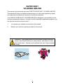
SUPER SHOT 125 DIESEL MELTER
PART MANUAL - 26378
REV. G
Revised: 03/06
2
SUPER SHOT 125 DIESEL MELTER
3
TABLE OF CONTENTS
Super Shot 125 Diesel Melter...................................................................................................... 5
Safety Precautions....................................................................................................................... 6-7
Limited Warranty.......................................................................................................................... 7
Warranty Claim Instructions......................................................................................................... 8
Specifications............................................................................................................................... 9
Introduction................................................................................................................................... 10
Operating Instructions
Machine Start Up...................................................................................................... 11-12
Dispensing the Material/Active Pump Protection..................................................... 13
Loading The Machine/Shutdown and Clean-out Procedures/Storing Machine.......14
Instructions For Ordering Parts/Electric Hose Care and Cautions.......................... 15
Hose Transport Instructions..................................................................................... 16
Maintenance
Maintenance Instructions.........................................................................................
Maintenance Chart/Service Instructions..................................................................
Recommended Fluids ans Lubricants/Typical Specifications.................................
Super Shot Pump Replacement..............................................................................
Super Shot Pump Replacement Diagram...............................................................
17
18
19
20
21
Trouble Shooting
Trouble Shooting Guide - Hose Does Not Heat...................................................... 22
Hose Circuit Diagram............................................................................................... 23
Trouble Shooting Guide - Hose Does Not Heat (continued)................................... 24
Trouble Shooting Guide - Material Does Not Dispense ......................................... 24
Hose Circuit Diagram............................................................................................... 25
Trouble Shooting Guide - Material Does Not Dispense.......................................... 26
Trouble Shooting Guide - Pump Rotates but No Material Is Discharged................ 26
Trouble Shooting Guide - Material Dispening Rate Too Slow................................. 26
Hose Circuit Diagram............................................................................................... 27
RTD Sensor - Ohms vs. Temperature...................................................................... 28
Diesel Burner Adjustments/Diesel Burner Settings.................................................. 29
Burner Schematic..................................................................................................... 30
Burner Trouble Shooting.......................................................................................... 31
Hydraulic Schematic................................................................................................. 32
Trouble Shooting Hydraulics.................................................................................... 33
Parts
SS125 Diesel Melter Diagrams and Parts...............................................................
Tank Detail Diagram and Parts................................................................................
Control Box Diagram and Parts...............................................................................
Engine Assembly Diagram and Parts......................................................................
Hydraulic Control Valve Diagram and Parts............................................................
Pump/Agitator Motor Assembly Diagram and Parts................................................
Diesel Burner Diagram and Parts............................................................................
Hydraulic Diagram and Parts...................................................................................
Electrical Cables and Parts......................................................................................
4
34-39
40-41
42-43
44-45
46
47
48-49
50-51
52-53
SUPER SHOT
125 DIESEL MELTER
This manual is furnished with each new CRAFCO SUPER SHOT 125 DIESEL MELTER.
This manual will help your machine operators learn to run the melter applicator properly
and understand its mechanical functions for trouble-free operation.
Your CRAFCO SUPER SHOT 125 DIESEL MELTER is designed to give excellent service
and save maintenance expense. However, as with all specially engineered equipment, you
can get best results at minimum costs if:
1.
You operate your machine as instructed in this manual.
2.
Maintain your machine regularly as stated in this manual.
WARNING: The engine exhaust from this product contains chemicals
known to the State of California to cause cancer, birth defects or other
reproductive harm. Operate in well ventilated area only. Engine exhaust
is deadly.
5
SAFETY PRECAUTIONS
• High operating temperatures of sealant and machine require protective clothing,
hard-soled shoes and heat resistant gloves to be worn by operator.
• Always wear eye protection.
• Observe all CAUTION AND WARNING signs posted on machine.
• Avoid the entrance of water into any part of the machine. Water will displace heat transfer
oil or sealant, which could be hazardous to personnel surrounding the machine when it
reaches operating temperatures.
• Avoid bodily contact with hot sealant material or heat transfer oil, serious burns may
result.
• Read Operator Manual thoroughly before operating machine.
• Make sure operator is familiar with machine operation.
• Do not operate in closed building or confined areas.
• Shut-down burner and engine prior to refilling diesel tank.
• When adding solid material to sealant tank, stop mixer, lift lid, place material onto lid and
close lid before restarting mixer. Hot material could splash and cause serious burns if this
procedure is not followed.
• Keep hands, feet, and clothing away from all moving parts.
• Always keep a fire extinguisher near the unit. Maintain extinguisher properly and be
familiar with its use.
•DO NOT exceed 525° F for heat transfer oil temperature.
• DO NOT overfill heat transfer oil level. Expansion of oil during heat up could cause
overflow. With machine in level position, check oil each day before starting burner, add oil
to top mark on dipstick if required (at 70° F.). Use only recommended heat transfer oil
and change after 500 hours of operation or one year, whichever occurs first.
• Follow operating instructions for starting and shut-down of burner. See Operating
Instructions.
• Calibrate temperature control prior to initial operation and each 50 hours of operation.
See Temperature Control Calibration.
6
SAFETY PRECAUTIONS
• Replace any hoses which show signs of wear, fraying, or splitting. Be sure all fittings and
joints are tight and leak-proof, each time machine is used.
•Precaution is the best insurance against accidents.
•The melter should not be left unattended with burner lit.
•Tighten all bolts and screws after every 100 hours of operation.
•Crafco, Inc. assumes no liability for an accident or injury incurred through improper use of
the machine.
LIMITED WARRANTY
Crafco, Inc., through its authorized distributor, will replace for the original purchaser free of
charge any parts found upon examination by the factory at Mesa, Arizona, to be
defective in material or workmanship. This warranty is for a period within 60 days of
purchase date, but excludes engine or components, tires, and battery as these items are
subject to warranties issued by their manufacturers.
After 60 days, Crafco, Inc., warrants structural parts, excluding heating system, hydraulic
components, material pump and hoses, hot oil pump, applicator valves, and electrical
components for a period of (1) one year from date of delivery. Crafco, Inc., shall not be
liable for parts that have been damaged by accident, alteration, abuse, improper lubrication/maintenance, normal wear, or other cause beyond our control.
The warranty provided herein extends only to the repair and/or replacement of those
components on the equipment covered above and does not cover labor costs. The
warranty does not extend to incidental or consequential damages incurred as a result of
any defect covered by this warranty.
All transportation and labor costs incurred by the purchaser in submitting or repairing
covered components must be borne by the purchaser.
Crafco, Inc. specifically disavows any other representation, warranty, or liability related to
the condition or use of the product.
WARNING: Use of replacement parts other than genuine Crafco parts
may impair the safety or reliability of your equipment and nullifies any
warranty.
7
WARRANTY CLAIM INSTRUCTIONS
Please follow the instructions stated below when calling in a warranty claim. Failure to
follow these procedures may be cause to void the warranty.
1.
Call your local Crafco Distributor. If you do not know who your local distributor is,
call a Crafco Customer Service Representative, (Toll Free 1-800-528-8242) for
name, location, and telephone number.
2.
On contacting the distributor, be prepared to identify the machine type, model
number, and serial number, also, the date of purchase if available.
3.
Should the cause of the malfunction be a defective part, the distributor will advise
you of the procedure to follow for a replacement.
4.
The warranty is valid only for parts, which have been supplied or recommended by
Crafco, Inc.
If you have any additional questions regarding warranty repairs and parts, please do not
hesitate to call toll free 1-800-528-8242.
CRAFCO, INCORPORATED
235 SOUTH HIBBERT DRIVE
MESA, AZ 85210
480-655-8333
Toll Free 1-800-528-8242
8
SPECIFICATIONS
Vat Capacity..................................................................
133 Gallons
Melt Capacity................................................................ 90 Gallons/Hour
Heat Transfer Oil Required...........................................34 Gallons at 70°F.
Tank Construction.........................................................Double Boiler Type
Tank Opening Size....................................................... 14” X 18”
Maximum Heat Input.................................................... 250,000 BTU’s
Burner and Temperature Control.................................. Diesel-Forced Air
Thermostatic Control
Engine - Isuzu...............................................................Twin Cylinder
Model 3CB1 - Diesel
25.4 BHP @ 3600 RPM
Hydraulic Drive Mechanism.......................................... All hydraulic with infinite
speed on mixer and material
pump.
Mixer............................................................................. Full sweep mixer with two
horizontal paddles
vertical risers.
Axle....................................................................................Single - 5,200 Lb. Torsional
Tires (2)........................................................................ ST225/75R15 Load Range D
Dry Weight....................................................................
Approximately 2,800 Lbs.
Diesel Tank Capacity....................................................
26 Gallons
Hydraulic Tank Capacity...............................................
26 Gallons
9
SUPER SHOT 125 DIESEL MELTER
OPERATING INSTRUCTIONS
INTRODUCTION
The CRAFCO SUPER SHOT 125 MELTER was developed to melt Crafco brand
sealant. However, it will work well with most road asphalt and federal specification crack or
joint sealant.
DO NOT operate machine without following these instructions:
1.
Fill fuel tank with diesel fuel (use #1 in cold weather, #2 in warm weather).
2.
Check engine crankcase oil level (refer to Engine Operator’s Manual).
3.
Check hydraulic fluid level, at 70°F. Add fluid if necessary.
4.
Check heat transfer oil level, at 70°F., the oil should be at the full mark on the
dipstick. DO NOT overfill or spillage may occur when oil is heated and
expands.
5.
The “POWER” switche should be turned “OFF” and all three temperature control dials
at minimum settings.
6.
Remember that safe operation of this equipment is the operator’s responsibility.
CAUTION:
Extreme care must be used when operating this equipment. Safety is the result
of being careful and paying attention to details. Remember the diesel flame is
about 2,200°F. Certain exposed parts of this machine when operating reach
500°F.; the sealant as high as 400°F. and the hydraulic fluid may reach 200°F.
Always wear protective clothing, hard-soled shoes, and eye protection. Be sure
that all joints and fittings are tight and leak proof. Immediately replace any hose
which shows any signs of wear, fraying, or splitting. Tighten all bolts, nuts, and
screws every 250 hours.
10
MACHINE START UP
TO START BURNER
1.
2.
3.
4.
Fully open the damper vent.
Start engine per Engine Manual.
Turn “POWER” toggle switch at control box “ON”.
Set hot oil temperature at 500°F. and material temperature at manufacturers
recommended temperature.
CAUTION:
If burner does not ignite the first time, turn toggle switch to “OFF.” Turn toggle
switch to “ON” again. Burner should ignite. If burner still does not ignite,
determine cause of malfunction (see Trouble Shooting Guide Pg. 22-26).
NOTE: The solid material in the tank melts first around the walls and bottom of the
material tank. Material temperature sensor is located by the wall; therefore, it is
possible that at the beginning of the melting process the indicated temperature
reaches operating value, but the material closer to the center of the tank is still solid.
This is normal and when the heated hose is ready for operation, most of the material
in the tank will be melted and heated to application temperature.
5.
Allow the heating oil to continue to heat. When sealant material reaches 275°F.
mixer may be engaged by turning the toggle switch at hydraulic control panel “ON”.
If the mixer does not move, allow the material to heat longer. Jamming of mixer
causes hydraulic oil to overheat and machine damage could occur. NOTE: Mixer
speed is preset at the factory and cannot be adjusted. Mixer cannot be
engaged until material reaches 275°F.
6.
Hose will automatically turn “ON” when material temperature reaches approximately
275°F. See Operating Instructions. Adjust the temperature dial to 380°F. or manufacturers recommended temperature. The hose will come up to temperature in
approximately 30 minutes. After the hose is hot, the light in the control box marked
“heated hose” will turn off and the temperature may be reduced to approximately
360°F. It is advisable to run the hose at the recommended temperature setting.
NOTE!! The hose must be up to 325°F. before dispensing can take place. If hose
does not dispense when trigger is activated then allow material to heat longer. If
hose still does not dispense material then shut machine down and locate plug in the
line and remove.
IMPORTANT!! DO NOT twist or kink hose. Avoid sharp bends and continuous
twisting. DO NOT exceed 400OF. setting on hose controller!! DO NOT move or bend
hose when cold Damage may result. Once you reach operating temperatures
DO NOT leave hose cycling for longer than 30 minutes without dispensing material.
Coking will occur and permanently damage your hose.
11
MACHINE START UP
IT IS STRONGLY RECOMMENDED THAT THE HOSE BE STORED IN THE
CORRECT LOCKED POSITION WHEN NOT IN USE OR WHEN IN TRANSIT.
7.
The heated hose supplied with the machine is Teflon lined with steel over braid. It
has a heating element, which runs down the hose to heat the material within the
hose. The hose is covered with high temperature, durable rubber hose. The wand
has an aluminum tube to protect both the wand and the operator. The pistol grip
actuator is equipped with an electric switch which when depressed sends a signal to
actuate the pump. At the end of the wand, a high temperature elastomeric output
valve is attached. The valve is pressure actuated and opens automatically when
fluid pressure is applied. The wand is equipped with a trigger lock to prevent
accidental pump actuation when not pumping material. The trigger should be in the
“LOCKED” position at all times except when intentionally pumping material.
12
DISPENSING THE MATERIAL
NOTE: PROTECTIVE CLOTHING, GLOVES, HARD SOLED SHOES,
AND FACE SHIELD OR SAFETY GLASSES SHOULD BE WORN
WHEN OPERATING OR FILLING THIS EQUIPMENT. READ
ENTIRE MANUAL BEFORE OPERATING.
The wand is equipped with a disposable duckbill valve on the end, which shuts off the flow of
material when the pump is turned off and prevents excessive dripping of material. This valve also
directs the material into a stream for easy application into the crack. Other sealing tips are
available. See your local distributor for options.
Some difficulty may be encountered when starting up on cold days. Although the wand is designed
to heat the material all the way down to the tip, on cold days it may be necessary to place the tip of
the wand under the lid to facilitate material melting in the valve. Insert the wand tip for only a short
time before proceeding.
When the material and the hose have reached proper application temperature, you are ready to
dispense material. Turn the pump speed control to the lowest setting by turning the speed control
knob fully counter clockwise. With the wand tip inserted into the top of the melter, depress trigger
on the wand and slowly increase pump speed by turning the speed control knob clockwise until the
pump motor starts to turn. Material should start to flow from the tip of the duckbill valve. Adjust the
pump speed for the desired rate of flow for the application and dispense material as required. The
rate of flow may be varied while the pump is running by rotating the control knob.
NEVER POINT THE WAND AT ANY PART OF THE BODY OR
AT ANY OTHER PERSON. HOT MATERIALS CAN CAUSE
SEVERE BURNS. WEAR PROTECTIVE EQUIPMENT WHEN
FILLING OR OPERATING THE EQUIPMENT. READ MANUAL
BEFORE OPERATING EQUIPMENT.
ACTIVE PUMP PROTECTION
The pump is completely encircled by a protective screen. The screen shall not allow anything larger than 1/2” (1.27 cm) in size to pass from the sealant tank into the pump suction
port. The screen shall continuously rotate 360 around the pump whenever the sealant
agitator is engaged. The active screen will protect the pump from foreign object damage
and will self clean as it rotates around the sealant pump and suction port.
13
LOADING THE MACHINE
When loading solid material into the sealant tank, the mixer will stop when the lid is lifted.
To load, lift the lid, place the material on the lid and close lid. Following this procedure will
prevent the hot material from splashing and causing serious burns to personnel.
The solid material must be added at intervals, which will allow the mixer to rotate without
jamming. If blocks of material are fed in too quickly, jamming will result and slow down the
melting process.
SHUTDOWN AND CLEAN-OUT PROCEDURE
When shutting down the machine for the day, there are several schools of thought about
how much material to leave in the machine. Crafco recommends leaving the melter about
half full. This will give a fairly rapid heat up rate in the morning, but will allow enough
material to start dispensing right away when the material becomes molten.
1.
Leaving the hose in the boom, swing the boom clockwise towards the front of the
machine and lock the boom into position with the latch provided.
2.
Place the wand in the wand holder and lock the wand into position with the latch
provided.
3.
Reverse the pump for approximately 30 seconds.
4.
Turn the mixer toggle switch to “OFF”.
5.
Turn the “POWER” switch to “OFF”.
6.
Shut the engine down by turning the key to the “OFF” position.
STORING MACHINE
The melter should be stored in an area where moisture cannot enter the machine heating
system such as hot oil, controls, etc. Extended down time can cause moisture build up in
heating oil tank.
If there is any suspicion that moisture may have collected in heat transfer oil, warm heat
transfer fluid to 300°F. for 2 to 3 hours to evaporate the moisture.
14
INSTRUCTIONS FOR ORDERING PARTS
Parts may be ordered from your local CRAFCO Distributor or directly from CRAFCO, Inc. if
a distributor is not available in your area. When ordering parts, give the following
information:
1.
Part number.
2.
Machine model.
3.
Serial number.
Write, telephone, or fax:
CRAFCO, INCORPORATED
420 N. Roosevelt Ave.
Chandler, Az. 85226-2601
Phone: 602-276-0406
Fax: 480-961-0513
Toll Free: 1-800-528-8242
ELECTRIC HOSE CARE AND CAUTIONS
Twisting and kinking of the electric hose (used on LF, BAX, SS60, SS125, and SS250
Melter) is the number one cause of hose failure.
When this happens, the electric heating wires are shorted out to the metal hose cover and
the hose stops heating.
This type of failure is not covered under the Crafco warranty.
To help prevent twisting and kinking and the resulting hose damage, the operator should:
a.
Not move or use hose unless it has been turned on at least 30 minutes and
set at a minimum temperature of 300OF.
b.
Make sure hose swivel between hose and wand moves freely.
c.
Avoid bending the hose over sharp edges such as the edge of the frame or
tank.
d.
Avoid twisting.
e.
Do not exceed 400OF. on the hose or material temperature.
f.
Follow all instructions of the melter as well as those in the instruction manual.
15
HOSE TRANSPORT INSTRUCTIONS
1.
Leaving the hose in the boom, swing the boom clockwise towards the front of the
machine and lock the boom into position with the latch provided.
2.
Place the wand in the wand holder and lock the wand into position with the latch
provided.
CAUTION:
Hose damage will occur if:
a.
Hose is bent or moved when cold.
b.
Hose is twisted or bent at sharp radius.
c.
Hose is moved prior to being turned on at least 35 minutes and set at
380O F.
d.
Operator crosses over or under hose causing hose to twist or wires between
hose and wand connection to twist or wrap up.
e.
Swivel is cold and not free to move allowing hose to twist.
f.
Hose to wand wiring is pulled, stressed, or used to support the wand.
16
MAINTENANCE INSTRUCTIONS
ENGINE
See Engine Owner Manual for operating and maintenance instructions.
HYDRAULIC SYSTEM
Check hydraulic fluid daily. Change hydraulic filter every 250 hours of operation. Change
hydraulic fluid every 500 hours of operation.
HEAT TRANSFER OIL
Check oil level every 8 hours of operation. Change oil every 500 hours of operation.
WHEEL BEARINGS
Re-pack wheel bearings every 24,000 miles or every two years, using a good grade of
bearing grease.
LUG NUTS
Wheel nuts/bolts should be torqued before first road use and after each wheel removal.
Check and retorque after the first 10 miles, 25 miles, and again at 50 miles. Check periodically thereafter. Torque in stages. 1st stage 20-25 ft.lbs., 2nd stage 50-60 ft.lbs., 3rd stage
90-120 ft.lbs.
TIGHTENING SEQUENCE
BRAKES
Check brakes daily. Refer to DEXTER AXLE Operation Maintenance Service Manual
located in the manual box.
TONGUE JACK
Lubricate tongue jack, using a good grade of bearing grease.
MIXER BEARING
Lubricate every 50 hours with good quality, high temperature grease.
TEMPERATURE CONTROL CALIBRATION
Check control knob calibration weekly.
1.
Calibrate by aligning the line on the control knob
with the calibration line on the scale plate (See Fig. 1).
Fig. 1
17
MAINTENANCE CHART
H OU R S
LOC ATION
PR OC ED U R E
8
50
250
500
Engi ne check oi l level
See Engi ne Instructi on Manual.
Other engi ne
mai ntenance
See Engi ne Operati ng and
Mai ntenance Instructi ons.
Battery
C heck water level weekly.
Heat transfer oi l
C heck.
Heat transfer oi l
C hange.
Hydrauli c oi l fi lter
C hange.
Hydrauli c oi l
C heck oi l.
Hydrauli c oi l
C hange oi l.
*
C heck burner box i nsulati on.
*
C lean cad cell.
*
C heck electrodes.
*
C heck blower brushes.
*
C heck nozzle pressure.
*
Burner
*
*
*
*
*
Wheel beari ngs
C lean & re-pack usi ng a good
grade of beari ng grease.
Tongue jack
Grease, usi ng good grade of
beari ng grease.
Every 24,000 mi les or every two years.
Once a year.
SERVICE INSTRUCTIONS
1.
Conduct a general inspection of your machine at least once a week. Replace all
worn or damaged parts, make any necessary adjustments and tighten all loose nuts
or screws.
2.
Keep regular replacement items in stock for emergency repairs and to avoid costly
“down” time.
3.
Watch for leaks. Tighten fitting or repair as necessary.
4.
Clean machine externally periodically. Check with sealant manufacturer for
recommendation.
5.
Follow recommended maintenance procedures on maintenance chart.
18
RECOMMENDED FLUIDS AND LUBRICANTS
APPLICATION
RECOMMENDED
FULL POINT
Engine oil
Refer to Isuzu owners manual.
3 Qts.
D i e se l
#1 Cold climate
#2 Warm climate
24 Gals.
Hydraulic oil
Rondo HD-68 Texaco
24 Gals.
Heat transfer oil
Regal R&O 68
34 Gals.
The following is a list of suitable heat transfer oil to be used in Crafco equipment.
PRODUCER
PRODUCT NAME
PRODUCT NUMBER
Texaco
Regal
R&O 68
Exxon
Caloria
HT 43
Arco
Rubilene
Citgo
Sentry
R&O 68
Gulf Oil Co.
Security
R&O 68
Shell Oil Co.
Therma
C
Chevron
Chevron Heat Transfer Oil
--
Conoco
Heat Transfer Oil
--
R&O 68
TYPICAL SPECIFICATIONS
ISO
Flash Point, COC
Viscosity @ 100° F.-SUS
Viscosity @ 210° F.-SUS
68
445° F.
325
50
Viscosity Index
Pour Point
Carbon Residue
95-100
0° F.
1%
WARNING:
The heat transfer oil in this machine is a grade that has been tested and
recommended by Crafco, Inc. The addition of any grade of oil not specifically
recommended by Crafco, Inc., shall be cause for warranties to be voided.
All oils subjected to high temperatures deteriorate with time and lose many of
their characteristics. Tests conducted by Crafco, Inc. have determined that for
best results and safety, the heat transfer oil in this machine must be drained
and replaced with Crafco, Inc. recommended oil after five hundred (500) hours
of operation or one (1) year, whichever occurs first.
19
SUPER SHOT PUMP REPLACEMENT
Step 1
Bring melter up to temperature as preparation for draining the material tank. Remove pipe cap located at rear of
machine and drain tank (CAUTION!! EXTREMELY HOT MATERIAL).
Step 2
Remove both guards from the motor mount to access the chain and sprockets.
Step 3
Rotate agitator until connecting link is accessible. Disassemble the connecting link and remove the drive
chain.
Step 4
Loosen set screw in the lower coupling half between the hydraulic motor and the drive shaft.
Step 5
Remove the (4) hydraulic hoses and cap off all ports. Note: Mark hoses for ease of replacement.
Step 6
Remove the (4) bolts holding motor mount on top of melter. Lift off motor mounting and set aside.
Step 7
Remove (2) bolts holding agitator shaft bearing. Note: Do not remove bearing from agitator shaft.
Step 8
When unit has cooled sufficiently, remove (6) bolts holding paddles on top of screen. Remove paddles from
tank.
Step 9
Remove pump drive shaft from center of agitator shaft then lift agitator shaft and screen assembly as high as
possible and insert screw driver into shaft hole. This will support the assembly while removing the pump from
the tank.
Step 10
Remove the (6) bolts, which fasten the pump to the tank. Lift the pump from the material tank (CAUTION!!
THE PUMP WEIGHS APPROXIMATELY 90LBS.)
Step 10
IMPORTANT: Clean any sealant from top of pump mounting plate and clean-out shaft holes. (WARNING!!!
PREMATURE PUMP WEAR WILL OCCUR IF THIS IS NOT DONE.)
20
SUPER SHOT PUMP REPLACEMENT
21
TROUBLE SHOOTING GUIDE
HOSE DOES NOT HEAT
Step 1: Is the “MATERIAL” temperature at 275°F?
YES: Go to step 2.
NO: Turn “POWER” toggle switch “ON”.
Step 2: Is “HEATED HOSE” light illuminated?
YES: Go to step 3.
NO: Check for tripped circuit breaker in front panel.
YES: Reset circuit breaker.
NO: Remove front panel and check for 12 volts at pink wire terminal #2
of the material Pak-Stat.
YES: Go to step 2a.
NO: Check for 12 volts at pink wire terminal #9 of the hose Pak-Stat.
Step 2a: Check for 12 volts at #3 terminal (pink wire) on the hose Pak-Stat.
YES: Go to step 2b.
NO: Check wire connections or go to step 1.
Step 2b: Check for 12 volts at #4 terminal (blue wire) when Pak-Stat is on.
YES: Go to step 3.
NO: Check the ohms between black and white wires at terminals #6 and #7.
(NOTE: One of the sensor wires must be diconnected to check
resistance) See page 28 for the corresponding temperature reading.
Temperature reading should match LCD readout.
YES: Replace Pak-Stat.
NO: Replace hose.
Step 3: Check for 12 volts at “BATT” terminal on generator.
YES: Go to step 4.
NO: Check 12 volts at terminal strip(blue wire) in control box.
Step 4: Check for 24 volts AC at the “BLACK”, “WHITE” and “GREEN” wires on the
generator. (Check between blk and wht, blk and grn, wht and grn.)
YES: Go to step 5.
NO: Replace generator.
22
23
TROUBLE SHOOTING GUIDE
Step 5: Check for 30 amps (cold) or 22-24 amps (hot) at the 3 blue wires in the
junction box. (Always use a clamp-on AMP meter to perform this test.)
YES: Hose should be operating properly.
NO: Go to step 6.
Step 6: Check for continuity between three heating element wires (blue) in junction
box. (NOTE: Wires must be disconnected from terminal block)
YES: Go to step 7.
NO: Check continuity between terminals “A”, “E”, and “D” at the wand.
YES: Wand is Ok. Go to step 7.
NO: Replace wand.
Step 7: Check for continuity between element wires (blue) and the fitting of the hose.
YES: Replace hose.
NO: Hose is OK.
MATERIAL DOES NOT DISPENSE WHEN PUMP IS ACTIVATED
Step 1: Is the motor coupling turning clockwise?
YES: Go to step 2.
NO: Has the sealant had sufficient time to completely melt?
YES: Go to step 2.
NO: Has the hose had sufficient time to reach operating temperature?
YES: Go to step 2.
NO: Allow hose to heat up to operating temperature.
Step 2: Is the “MATERIAL” temperature at 275°F ?
YES: Go to step 3.
NO: Allow material to heat longer or turn “POWER” toggle switch “ON”.
Step 3: Is the “PUMP” light illuminated?
YES: Go to step 4.
NO: Hose temperature must be at 325°F before the pump will activate.
Step 4: Check for 12 volts at terminals #12 (red-blk wire) and terminal #14 (green
wire) of the relay. (NOTE: Terminal #12 will have 12 volts when the key
is “ON”. Terminal #14 will have 12 volts when trigger is activated.)
YES: Go to step 4a.
NO: Check continuity of red trigger wires in junction box.
Yes: Go to step 5.
No: Check for continuity between terminals “C” and “B” on wand when the
trigger is activated.
YES: Go to step 5.
NO: Replace trigger or check for poor connections.
Step 4a: Check relay by pressing the white test button on top of relay. (CAUTION:
Pump will dispense material)
YES: Go to step 5.
NO: Replace relay.
24
25
TROUBLE SHOOTING GUIDE
Step 5: Is the top right light on hydraulic valve illuminated (looking at the rear of the
hydraulic valve) when trigger is activated?
YES: Replace hydraulic cartridge.
NO: Go to step 4.
PUMP ROTATES BUT NO MATERIAL IS DISCHARGED
Step 1: Has the sealant and heated hose had sufficient time to reach temperature?
YES: Go to step 2.
NO: Allow the sealant and hose to heat longer.
Step 2: Check material outlet pipe and connection between hose and wand for
obstruction.
YES: Remove obstruction and reassemble hose connection.
NO: Go to step 3.
Step 3: Is there an obstruction at the pump suction?
YES: Reverse material pump for 30 seconds.
NO: Refer to page 20 for pump removal if required.
MATERIAL DISPENSING RATE IS TOO SLOW
Step 1: Check speed control knob for desired flow adjustment.
YES: Go to step 2.
NO: Adjust to desired flow.
Step 2: Is there enough material in the tank?
YES: Go to step 3.
NO: Add enough material to bring tank level above the screen.
Step 3: Check material outlet pipe and connection between hose and wand for
obstruction.
YES: Remove obstruction and reassemble hose connection.
NO: Pump is worn out. (See page 20 for pump removal and installation.)
26
27
RTD SENSOR - OHMS vs. TEMPERATURE
The following chart shows what the ohm reading would be for a given temperature.The following are the instructions for use.
1.
Measure the resistance (Ohms) of the sensor in question with an Ohm meter.
2.
Find the reading in the chart.
3.
Follow the row to the left and get the temperature in 10° increment, then follow the
column up to get the 1° increment. Example: 1573 Ohms =302°
°F
0
1
2
3
4
5
6
7
8
9
930.3
932.5
934.7
936.9
939.1
941.3
943.4
945.6
947.8
950.0
10
952.2
954.3
956.5
958.7
960.9
963.0
965.2
967.4
969.6
971.8
20
973.9
976.1
978.3
980.5
982.6
984.8
987.0
989.1
991.3
993.5
0
30
995.7
997.8
1000.0
1002.2
1004.3
1006.5
1008.7
1010.9
1013.0
1015.2
40
1017.4
1019.5
1021.7
1023.9
1026.0
1028.2
1030.4
1032.5
1034.7
1036.9
1058.5
50
1039.0
1041.2
1043.4
1045.5
1047.7
1049.8
1052.0
1054.2
1056.3
60
1060.7
1062.8
1065.0
1067.1
1069.3
1071.5
1073.6
1075.8
1077.9
1080.1
70
1082.2
1084.4
1086.6
1088.7
1090.9
1093.0
1095.2
1097.3
1099.5
1101.6
80
1103.8
1106.0
1108.1
1110.3
1112.4
1114.6
1116.7
1118.9
1121.0
1123.2
90
1125.3
1127.5
1129.6
1131.8
1133.9
1136.1
1138.2
1140.4
1142.5
1144.7
100
1146.8
1149.0
1151.1
1153.2
1155.4
1157.5
1159.7
1161.8
1164.0
1166.1
110
1168.3
1170.4
1172.5
1174.7
1176.9
1179.0
1181.1
1183.3
1185.4
1187.5
120
1189.7
1191.8
1194.0
1196.1
1198.2
1200.4
1202.5
1204.6
1206.8
1208.9
130
1211.0
1213.2
1215.3
1217.5
1219.6
1221.7
1223.9
1226.0
1228.1
1230.3
140
1232.4
1234.5
1236.7
1238.9
1240.9
1243.0
1245.2
1247.3
1249.4
1251.6
150
1253.7
1255.8
1258.0
1260.1
1262.2
1264.3
1266.5
1268.6
1270.7
1272.8
160
1275.0
1277.1
1279.2
1281.3
1283.5
1285.6
1287.7
1289.8
1292.0
1294.1
170
1296.2
1298.3
1300.4
1302.6
1304.7
1306.8
1308.9
1311.0
1313.2
1315.3
1336.5
180
1317.4
1319.5
1321.6
1323.8
1325.9
1328.0
1330.1
1332.2
1334.3
190
1338.6
1340.7
1342.8
1344.9
1347.0
1349.1
1351.2
1353.4
1355.5
1357.6
200
1359.7
1361.8
1363.9
1366.0
1368.1
1370.2
1372.4
1374.5
1376.6
1378.7
210
1380.8
1382.9
1385.0
1387.1
1389.2
1391.3
1393.4
1395.5
1397.6
1399.7
220
1401.8
1403.9
1406.0
1408.1
1410.3
1412.4
1414.5
1416.6
1418.7
1420.8
230
1422.9
1425.0
1427.1
1429.2
1431.3
1433.4
1435.5
1437.6
1439.6
1441.7
240
1443.8
1445.9
1448.0
1450.1
1452.2
1454.3
1456.4
1458.5
1460.6
1462.7
250
1464.8
1466.9
1469.0
1471.1
1473.2
1475.3
1477.3
1479.4
1481.5
1483.6
260
1485.7
1487.8
1489.9
1492.0
1494.1
1496.1
1498.2
1500.3
1502.4
1504.5
270
1506.6
1508.7
1510.8
1512.8
1514.9
1517.0
1519.1
1521.2
1523.3
1525.3
280
1527.4
1529.5
1531.6
1533.7
1535.7
1537.8
1539.9
1542.0
1544.1
1546.1
290
1548.2
1550.3
1552.4
1554.5
1556.5
1558.6
1560.7
1562.8
1564.8
1566.9
1587.7
300
1569.0
1571.1
1573.1
1575.2
1577.3
1579.4
1581.4
1583.5
1585.6
310
1589.7
1591.8
1593.9
1595.9
1598.0
1600.1
1602.2
1604.2
1606.3
1608.4
320
1610.4
1612.5
1614.6
1616.6
1618.7
1620.8
1622.8
1624.9
1627.0
1629.0
330
1631.1
1633.2
1635.2
1637.3
1639.3
1641.4
1643.5
1645.5
1647.6
1649.7
340
1651.7
1653.8
1655.8
1657.9
1660.0
1662.0
1664.1
1666.1
1668.2
1670.2
1690.8
350
1672.3
1674.4
1676.4
1678.5
1680.5
1682.6
1684.6
1686.7
1688.7
360
1692.9
1694.9
1697.0
1699.0
1701.1
1703.1
1705.2
1707.2
1709.3
1711.3
370
1713.4
1715.4
1717.5
1719.5
1721.6
1723.6
1725.7
1727.7
1729.8
1731.8
380
1733.9
1735.9
1737.9
1740.0
1742.0
1744.1
1746.1
1748.2
1750.2
1752.3
390
1754.3
1756.3
1758.4
1760.4
1762.5
1764.5
1766.6
1768.6
1770.6
1772.7
400
1774.7
1776.8
1778.8
1780.8
1782.9
1784.9
1786.9
1789.0
1791.0
1793.1
410
1795.1
1797.1
1799.2
1801.2
1803.2
1805.3
1807.3
1809.3
1811.4
1813.4
420
1815.4
1817.5
1819.5
1821.5
1823.6
1825.6
1827.6
1829.6
1831.7
1833.7
430
1835.7
1837.8
1839.8
1841.8
1843.8
1845.9
1847.9
1849.9
1851.9
1854.0
440
1856.0
1858.0
1860.0
1862.1
1864.1
1866.1
1868.1
1870.2
1872.2
1874.2
450
1876.2
1878.2
1880.3
1882.3
1884.3
1886.3
1888.3
1890.4
1892.4
1894.4
460
1896.4
1898.4
1900.5
1902.5
1904.5
1906.5
1908.5
1910.5
1912.6
1914.6
470
1916.6
1918.6
1920.6
1922.6
1924.6
1926.6
1928.7
1930.7
1932.7
1934.7
480
1936.7
1938.7
1940.7
1942.7
1944.7
1946.8
1948.8
1950.8
1952.8
1954.8
490
1956.8
1958.8
1960.8
1962.8
1964.8
1966.8
1968.8
1970.8
1972.8
1974.8
500
1976.8
1978.8
1980.8
1982.9
1984.9
1986.9
1988.9
1990.9
1992.9
1994.9
510
1996.9
1998.9
2000.9
2002.9
2004.9
2006.9
2008.8
2010.8
2012.8
2014.8
520
2016.8
2018.8
2020.8
2022.8
2024.8
2026.8
2028.8
2030.8
2032.8
2034.8
530
2036.8
2038.8
2040.8
2042.8
2044.7
2046.7
2048.7
2050.7
2052.7
2054.7
540
2056.7
2058.7
2060.7
2062.7
2064.6
2066.6
2068.6
2070.6
2072.6
2074.6
550
2076.6
2078.5
2080.5
2082.5
2084.5
2086.5
2088.5
2090.4
2092.4
2094.4
28
DIESEL BURNER ADJUSTMENTS
DIESEL BURNER SETTINGS
Air Shutter = 7
Air Band = 0
Fuel Pressure = 140 PSI
Adjustment Plate = 3
Use fuel and hydraulic pressure gauge kit part number 29960.
29
BURNER SCHEMATIC
30
BURNER TROUBLE SHOOTING
BURNER WILL NOT IGNITE
Step 1:Check for 12 volts at “POWER” toggle switch.
No: Engine key “OFF”
Toggle switch “OFF”
Blown fuse
Broken wire
YES: 12 volts at terminal #4 on “MATERIAL” Pak-Stat
NO: Bad Pak-Stat
Faulty sensor
YES: Check for 12 volts at terminal #7 on “OIL” Pak-Stat
NO: Bad Pak-Stat
Faulty sensor
YES: Check for 12 volts at solenoid (frame).
NO: Bad solenoid
Bad connection at battery
Faulty circuit breaker
Broken or loose wire
YES: Faulty DC Controller, poor ground / loose wire
Faulty or dirty flame
Faulty igniter transformer, cracked electrode
(ceramic)
Incorrect igniter gap
Faulty fuel solenoid
Bleed fuel pump / check fuel pump coupling
Fuse under DC Controller
Blower motor relay
Faulty blower motor
Alternator charging @ 14 volts
Faulty 12 volt battery
BURNER LIGHTS BUT SHUTS DOWN AFTER 15 SEC.
Faulty flame eye
Broken, loose flame eye sensor wires, receptacle
Faulty DC Controller
Bleed fuel system if white or blue smoke appears through exhaust stack
BURNER LIGHTS BUT WILL NOT RELIGHT
Bad connection at battery
Broken or loose wires
Faulty DC Controller
Alternator charging at 14 volts
Faulty 12 volt battery
EXCESSIVE SMOKE FROM BURNER EXHAUST
Air vent incorrectly set - set at 7
Blower motor not turning at correct speed
Alternator charging at 14 volts
Faulty 12 volt battery
31
HYDRAULIC SCHEMATIC
Flow = 7.5 GPM @ 2400 RPM
Relief Valve (RVA) = 1300 PSI
Relief Valve (RVM) = 1800 PSI
32
TROUBLE SHOOTING HYDRAULICS
PROBLEM
CAUSE
REMEDY
Mixer will not rotate.
Sealant temperature too low.
Continue to heat material.
Mixer will not rotate.
Too many blocks placed at one
time.
Continue to heat material.
Mixer will not rotate.
Inadequate hydraulic flow/pressure. Check hydraulic fluid level.
Mixer will not rotate.
Toggle switch turned off.
Reset pressure, check flow if
necessary.
Material pump will not rotate.
Material in tank not to operating
temperature.
Continue heating material.
Material pump will not rotate.
Inadequate hydraulic flow/pressure.
Check hydraulic fluid level. Reset
pressure, check flow as necessary.
Material pump will not rotate.
Material pump damaged.
Remove and replace.
Material pump will not rotate.
Foreign object lodged in pump.
Remove pump, clean & replace.
Material pump will not rotate.
Temperature at wand tip is
inadequate.
Set wand tip inside material tank.
Material pump will not rotate.
Bad switch at wand.
Remove and replace.
Material pump will not rotate.
Hydraulic cartridge failure.
Remove and replace.
Material pump will not rotate.
Hydraulic coil failure.
Remove and replace.
When applying sealant it stops
flowing from applicator wand.
Tank fluid level too low for material
to flow into pump.
Add more material or continue
heating material until more liquid
material is available.
Pump rotates, but will not pump
material.
Material cold, inlet still solid.
Hose not to temperature.
Temperature at wand tip is
inadequate.
Continue to heat material.
Allow to heat longer. Set wand tip
inside material tank.
Pump does not rotate.
Bad wire connection.
Bad switch at wand handle.
Hydraulic cartridge failure.
Hydraulic coil failure.
Find bad repair.
Remove and replace.
Remove and replace.
Remove and replace.
Built up of coked material on
inside of material tank.
Allow machine to cool.
Remove deposits and flush with
solvent.
Make sure fluid level is correct.
Set at recommended temperature.
Slow heat up of sealant.
Low heating oil level.
Low heating oil temperature.
33
SS 125 MELTER
34
SS 125 MELTER PARTS LIST
N U MB ER
PAR T
N U MB ER
QTY.
1
44342
2
TIRE AND WHEEL ASSEMBLY
2
43535
1
TORSIONAL AXLE ASSEMBLY
3
44778
1
D RIVER SID E FEND ER ASSEMBLY
4
44779
1
PASSENGER SID E FEND ER ASSEMBLY
5
44771
2
4" RED STOP,TURN AND TAIL LIGHT
6
44772
2
2 1/2" RED SID E MARKER
7
23082
1
TONGUE JAC K
8
23095
1
SWIVEL BUSHING
9
23117
1
BREAKAWAY SWITC H
10
43076
1
ENGINE ASSEMBLY
11
29399
4
ISOMOUNT
12
44821
1
C OVER - C ONTROL VALVE
13
39602
1
SOLENOID
14
43595
1
HYD RAULIC TANK ASSEMBLY
15
43579
2
FILLER / BREATHER
16
43594
1
FUEL TANK ASSEMBLY
17
44807
1
SIGHT GAUGE
18
41891
1
14 VOLT BURNER
19
43114
1
C OVER - BURNER
20
44804
1
HYD RAULIC FILTER ASSEMBLY
20a
44805
1
HYD RAULIC FILTER ELEMENT
20b
44838
-
O-RING, HYD RAULIC FILTER
20c
44839
-
GASKET, HYD RAULIC FILTER
21
44820
1
C ONTROL VALVE ASSEMBLY
22
32513
1
TOGGLE SWITC H - PUMP REVERSE
23
51678
1
TOGGLE SWITC H - AGITATOR
24
50720
2
BOOT - TOGGLE SWITC H
D ESC R IPTION
35
SS 125 MELTER
36
SS 125 MELTER PARTS LISTS
N U MB ER
PAR T
N U MB ER
QTY.
25
44971
1
C ONTROL BOX ASSEMBLY
26
43465
2
SENSOR, RTD
27
51065
2
C ORD GRIP
28
43355
1
OVERFLOW TANK
29
43673
1
D IPSTIC K
30
26025
1
AIR BREATHER
31
44832
1
PUMP/AGITATOR MOTOR ASSEMBLY
32
43727
2
C HAIN GUARD ASSEMBLY
33
44818
1
TUBING, FUEL SIGHT GAUGE
34
44817
2
FITTING, SIGHT GAUGE
35
45550
1
BOOM - HOSE
36
45549
1
BASE - BOOM
37
45562
1
HOSE GUID E
38
43821
1
HEAT GUARD
39
44027
1
JUNC TION BOX ASSEMBLY
40
51776
1
ELEC TRIC HEATED HOSE ASSEMBLY - 18 FT.
41
51730
1
ELEC TRIC HEATED WAND ASSEMBLY - 48"
42
43768
1
WAND HAND LE
43
39608
1
SWITC H
44
24076
1
HOUR METER
45
41948
1
KEY AND TUMBLER
46
20130
2
48" SAFETY C HAIN
47
24000
1
BATTERY
48
24002
1
BATTERY BOX
49a
43672
OPT.
MOUNT - STROBE LIGHT
49b
24095
OPT.
STROBE LIGHT
D ESC R IPTION
37
SS 125 MELTER
38
SS 125 MELTER PARTS LIST
N U MB ER
PAR T
N U MB ER
QTY.
50
31512
1
51
24190
OPT.
OVERNIGHT HEATER
52
43540
OPT.
SPARE TIRE MOUNT
53
51756
1
54
27162R
OPT.
3" D ISK W/ RESTRIC TOR
55
27163R
OPT.
4" D ISK W/ RESTRIC TOR
56
27170
OPT
3/8 ROUND SEALING TIP
57
27171
OPT.
1/2" ROUND SEALING TIP
58
27173
OPT.
3/4" SEALING SHOE
59
27146
OPT.
1/4" ELONGATED SEALING TIP
60
45558
1
WAND SUPPORT
61
45559
1
LOC KING ARM, WAND SUPPORT
62
26103
1
1/4 X .5 GRIP QUIC K RELEASE PIN
D ESC R IPTION
C IRC UIT BREAKER
AD APTER, D UC KBILL
39
TANK DETAIL
40
TANK DETAIL
ITEM
PAR T
N U MB ER
QTY
1
44165
1
SPROC KET - D RIVEN
2
44163
1
KEY, SPROC KET
3
43321
1
C HAIN - D RIVE
4
43760
1
BEARING, FLANGED
5
43753
1
SHAFT - AGITATOR
6
43641
1
SHAFT, D RIVE - PUMP
7
31368
1
KEY - D RIVE SHAFT
8
44850
1
PUMP, MATERIAL
9
43655
1
SC REEN - PUMP
10
43649
2
PAD D LE - AGITATOR
11
28132
1
1" X 10" LG. PIPE NIPPLE
12
28270
1
1" PIPE C AP
13
28046
1
2" X 4" LG. PIPE NIPPLE
14
28273
1
2" PIPE C AP
15
28039
1
1" X 4" LG. PIPE NIPPLE
16
28210
1
1" PIPE ELBOW
17
28351
1
1" X 3/4" RED UC ER BUSHING
D ESC R IPTION
41
CONTROL BOX
42
CONTROL BOX
N U MB E R
PAR T
N U MB E R
QTY.
1
44970
1
E NC LOS URE (NOT S HOWN)
2
40446
3
C ORD C ONNE C TOR 1/2"
3
50280
4
1/2" C OND UIT NUT
4
51662
1
S OC K E T - RE LAY
5
51661
1
RE LAY
6
51663
1
HOLD D OWN S P RING
7
51691
1
TE MP E RATURE C ONTROLLE R, 400° / 325°
8
51672
1
TE MP E RATURE C ONTROLLE R, 400° / 275°
9
51803
1
MOUNTING RA IL
10
51802
2
E ND B RA C K E T
11
51800
25
12
51801
1
2-P OLE JUMP E R
13
51804
1
3-P OLE JUMP E R
14
50251
3
D IGITA L RE A D OUT
15
43391
1
TE MP E RATURE C ONTROLLE R, 150°-550°
16
51651
4
LIGHT, 12V D C
17
50719
1
TOGGLE S WITC H
18
51665
1
C IRC UIT B RE A K E R, 15 A MP
19
50593
3
K NOB
20
44983
1
C A B LE A S S Y. - S E NS OR
21
44984
1
C A B LE A S S Y. - P OWE R
22
44985
1
C A B LE A S S Y. - TRIGGE R/S E NS OR
23
51684
2
RIB B ON C A B LE , 36" (NOT S HOWN)
24
51670
8
S PA C E R, PA K -S TAT
25
44993
1
MOUNTING RA IL 2 3/4"
26
24024
1
1" C ORD GRIP
27
44978
1
WIRING HA RNE S S
28
44994
1
TE RMINA L B LOC K (5 P OLE )
29
41994
1
IGNITION S WITC H
30
24076
1
HOUR ME TE R
31
44979
2
RE LAY S TA RTE R
32
44980
1
TIME R
D E S C R IP TION
FE E D THROUGH TE RMINA L
43
ENGINE ASSEMBLY
PRESET ENGINE SPEED = 2400 RPM
HOSE GENERATOR OUTPUT = 30-35 AMPS COLD
24 VAC 3-PHASE
44
ENGINE ASSEMBLY
NUMBER
PART
NUMBER
QTY.
1
45745
1
ENGINE, 23 HP
2
43899
1
ADJUSTMENT BRACKET, GENERATOR
3
44871
1
HYDRAULIC PUMP
4
29819
1
3/4 TUBE X 1 1/16-12 O-RING ADAPTOR
5
29812
1
5/8 TUBE X 7/8-14 0-RING ADAPTOR
6
43613
1
DRIVE BELT - GENERATOR
7
43612
1
GENERATOR, 24VAC
8
45389
-
OIL FILTER
9
41867
-
FUEL FILTER
10
45391
-
AIR FILTER ELEMENT
DESCRIPTION
45
HYDRAULIC CONTROL VALVE
N U MB ER
PAR T
N U MB ER
QTY.
1
44895
1
HYD RAULIC VALVE ASSEMBLY
2
44889
4
C OIL-C ONTROL VALVE
3
44888
2
C ARTRID GE - PUMP
4
44813
1
FLOW C ONTROL
5
44812
2
RELIEF VALVE
6
44811
1
FLOW C ONTROL, 1.5 GAL.
7
29919
2
9/16-18 O-RING X 3/4-16 TUBE AD APTER
8
40311
2
9/16-18 O-RING X 9/16-18 TUBE AD APTER
9
29896
1
3/4-16 O-RING ELBOW AD APTER
10
29897
1
3/4-16 STR. THRD . O-RING AD APTER
D ESC R IPTION
46
PUMP / AGITATOR MOTOR ASSEMBLY
N U MB ER
PAR T
N U MB ER
QTY.
1
43345
1
MOUNTING BRAC KET - MOTORS
2
44809
1
HYD RAULIC MOTOR - PUMP
3
22027
1
HYD RAULIC MOTOR - AGITATOR
4
22029
4
3/8 TUBE X 5/8 O-RING AD APTOR
5
26002
2
SPROC KET - C HAIN C OUPLING
6
26016
1
C HAIN - C OUPLING
7
26030
1
C ONNEC TING LINK - C HAIN
8
31368
1
KEY, 1/4 X 7/8
9
43323
1
SPROC KET - AGITATOR D RIVE
D ESC R IPTION
47
DIESEL BURNER
48
DIESEL BURNER
ITEM
PART
NUMBER
QTY
1
41949
-
IGNITION TRANSFORMER
2
41890
-
BLOWER MOTOR
3
41934
-
BRUSH KIT - MOTOR
4
41970
-
COUPLING - FUEL PUMP
5
41979
-
PUMP - FUEL
6
41888
-
SOLENOID - FUEL
7
41993
-
ELECTRODE
8a
41883
-
NOZZLE (SS125D, SS125DC, SS125DCRC)
8b
41881
-
NOZZLE (SS250D, SS250DC, SS250DRC)
8c
42559
-
NOZZLE (350D, 400D)
9
41870
-
CAD EYE (NOT SHOWN)
10
42335
-
DC CONTROLLER (NOT SHOWN)
DESCRIPTION
49
HYDRAULIC DIAGRAM
AGITATOR DIRECTION = COUNTERCLOCKWISE
MATERIAL PUMP DIRECTION = CLOCKWISE
HYDRAULIC FLOW = 7.5 GPM @ 2400 RPM
RELIEF VALVE (RVA) = 1300 PSI
RELEIF VALVE (RVM) = 1800 PSI
50
HYDRAULIC DIAGRAM
1.
2.
3.
4.
5.
6.
7.
HYDRAULIC RESERVOIR TO HYDRAULIC PUMP SUCTION
REF
29948
1
C12-16FJ-12FJ-24
1
29819
1 1/4 NPT X 1" TUBE ELBOW
HYDRAULIC HOSE ASSEMBLY 3/4 X 24" LONG
3/4 TUBE X 1-1/16-12 O-RING
HYDRAULIC PUMP TO HYDRAULIC VALVE "P" PORT
1
29812
1
AX6-10FJ-8FJ9L-94
1
29897
5/8 TUBE X 7/8-14 O-RING ADAPTER
HYDRAULIC HOSE ASSEMBLY 3/8 X 94" LONG
1/2 TUBE X 3/4-16 O-RING ADAPTER
HYDRAULIC VALVE "A" PORT TO MAT'L PUMP MOTOR
1
40311
1
AX6-6FJ-6FJ9L-20
1
22029
3/8 TUBE X 9/16-18 O-RING ADAPTER
HYDRAULIC HOSE ASSEMBLY 3/8 X 20" LONG
3/8 TUBE X 7/8-14 O-RING ADAPTER
HYDRAULIC VALVE "PMP B" PORT TO MAT'L PUMP MOTOR
1
29919
1
AX6-8FJ-6FJ9-18
1
22029
1/2 TUBE X 9/16-18 O-RING ADAPTER
HYDRAULIC HOSE ASSEMBLY 3/8 X 18" LONG
3/8 TUBE X 7/8-14 O-RING ADAPTER
HYDRAULIC VALVE "AGIT B" PORT TO MIXER MOTOR
1
29919
1
AX6-8FJ-6FJ9-24
1
22029
1/2 TUBE X 9/16-18 O-RING ADAPTER
HYDRAULIC HOSE ASSEMBLY 3/8 X 22" LONG
3/8 TUBE X 7/8-14 O-RING ADAPTER
MIXER MOTOR TO HYDRAULIC VALVE "AGIT A" PORT
1
22029
1
AX6-6FJ-6FJ9L-26
1
40311
3/8 TUBE X 7/8-14 O-RING ADAPTER
HYDRAULIC HOSE ASSEMBLY 3/8 X24" LONG
3/8 TUBE X 9/16-18 O-RING ADAPTER
HYDRAULIC VALVE "T" PORT TO HYDRAULIC FILTER
1
29896
1
AX8-8FJ-12FJ9-74
1
29816
1/2 TUBE X 7/8-14 O-RING ELBOW ADAPTER
HYDRAULIC HOSE ASSEMBLY 1/2 X 70" LONG
3/4 TUBE X 1 5/16" O-RING ADAPTER
51
ELECTRICAL CABLES
52
ELECTRICAL CABLES
ITEM
PART
NUMBER
QTY
1
44983
1
SENSOR CABLE ASSEMBLY
2
44984
1
POWER CABLE ASSEMBLY
3
44985
1
TRIGGER/SENSOR CABLE ASSEMBLY
4
43901
1
HOSE CABLE ASSEMBLY
5
43921
1
CABLE ASSEMBLY - VALVE
6
24015
1
BATTERY CABLE, 38" - POSITIVE
7
24010
1
BATTERY CABLE, 12" - GROUND
8
37038
1
BATTERY CABLE, 22" - ENGINE GROUND
DESCRIPTION
53
54
Pioneering Leadership and
Innovation in Quality
Pavement Maintenance
Products.
235 South Hibbert · Mesa, Arizona 85210
480-655-8333 · Watts 1-800-528-8242
Fax 480-655-1712
ÓCopyright 2002 by Crafco, Inc.