1
SERVICE MANUAL
.-
-~~'._"'-!II
=ftf:-.::4-...
~...... __
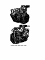
MITSUBISHI
DIESEL ENGINE
4DQ50
MITSUBISHI DIESEL ENGINE MODEL 4DQ5OW
MITSUBISHI DIESEL ENGINE MODEL 4DQSOC
CONTENTS
PREFACE . . . . . . . . . . . . . . . . . . . . . . . . . . . . . . . . . . . . . . . . . . . . . . . . . . .
.........................
2
Newengine . . . . . . . . . . . . . . . . . . . . . . . . . . . . . . . . . . . . . . . . . . . . . .
2
2
Checkup and preparations prior to starting . . . . . . . . . . . . . . . . . . . . . . . . .
2
3
Engine starting
4
4
After the engine's start . . . . . . . . . . . . . . . . . . . . . . . . . . . . . . . . . . . . . . .
5
5
Engine operation
5
6
During operation . . . . . . . . . . . . . . . . . . . . . . . . . . . . . . . . . . . . . . . . . .
5
7
Stopping
...............................................
6
8
Handling in cold weather . : . . . . . . . . . . . . . . . . . . . . . . . . . . . . . . . . . . .
7
CHAPTER 1
9
OPERATION AND HANDLING
8-1
Starting in cold weather
..................................
7
8-2
General instructions . . . . . . . . . . . . . . . . . . . . . . . . . . . . . . . . . . . . .
7
Handling in the hot season . . . . . . . . . . . . . . . . . . . . . . . . . . . . . . . . . . . .
8
CHAPTER 2 FUEL, OIL AND COOLING WATER
9
1
Fuel.....................................................
9
2
Engine oil . . . . . . . . . . . . . . . . . . . . . . . . . . . . . . . . . . . . . . . . . . . . . . .
9
2-1
Quality required of engine oil ... . . . . . . . . . . . . . . . . . . . . . . . . . . ..
9
2-2
Recommendable classes of engine oil . . . . . . . . . . . . . . . . . . . . . . . . . .
9
2-3
Time to change engine oil
. . . . . . . . . . . . . . . . . . . . . . . . . . . . . . . . . 10
3
Diaphragm oil • . . . . . . • . . . . . . . . . . . . . . . . . . . . . . . . . . . . . . . . . . . . 10
4
Cooling water
. . . . . . . . . . . . . . . . . . . . . . . . . . . . . . . . . . . . . . . . . . . . 10
4-1
Required quality . . . . . . . . . . . . . . . • . . . . . . . . . . . . . . . . . . . . . . . 10
4-2
Handling of cooling system
. . . . . . . . . . • . . . . . . . . . . . . . . . . . . . . . 10
CHAPTER 3 REGULAR SERVICING. . . . . . . . . . . . . . . . . . . . . . . . . . . . . . .. 11
Lubrication .......... . . . . . . . . . . . . . . . . . . . . . . . . . . . . . . . . . . .. 11
2
Air system
. . . . . . . . . . . . . . . . . . . . . . . . . . . . . . . . . . . . . . . . . . . . . . 15
3
4
2·1
Air cleaner (oil bath type) . . . . . . . . . . . . . . . . . . . . . . . . . . . . . . . . . 15
2·2
Air cleaner (filter paper type) . . . . . . . . . . . . . . . . . . . . . . . . . . . . . . . 16
2·3
Valve clearances
2·4
Compression pressure . . . . . . . . . . . . . . . . . . . . . . . . . . . . . . . . . . . . 18
Oil system
. . . . . . . . . . . . . . . . . . . . . . . . . . . . . . . . . . . . . . . 18
. . . . . . . . . . . . . . . . . . . . . . . . . . • . . . . . . . . . . . . . . . . . . . 18
3·1
Oil pan
3·2
Oil filter . . . . . . . . . . . . . . . . . . . . . . . . . . . . . • . . . . . . . . . . . . . "
3·3
Differential bypass valve . . . . . . . . . . . . . . . . . . . . . . . . . . . . . . . . . . 20
3-4
Oil pressure
Fuel system
. . . . . . . . . . . . . . . . . . . . . . . . . . . . . . . . . . . . . . . . . . . . . 19
20
. . . . . . . . . . . . . . . . . . . . . . . . . . . . . . . . . . . . . . . . . . 21
. . . . . . . . . . . . . . . . . . . . . . . . . . . . . . . . . . . . . . . . . . . . . 22
4·1
Fuel filter . . . . . . . . . . . . . . . . . . . . . . . . . . . . . . . . . . . . . . . . . . . . 22
4-2
Bleeding (or priming)
4·3
Checkup of nozzles
4·4
Fuel injection pump . . . . . . . . . . . . . . . . . . . . • . . . . . . . . . . . . . . . . 26
4·5
Fuel injection timing
4·6
Governor (pneumatic)
• . . . . . . . . . . . . . . . . . . . . . . . . . . . . . . . . . . 28
4·7
Governor (mechanical)
. . . . . . . . . . . . . . . . . . . . . . . . . . . . . . . . . . . 31
. . . . . . . . . . . . . . . . . . . . . . . . . . . . . . . . . . . . 24
. . . . . . . . . . . . . . . . . . . . . . . . . . . . . . . . . . . . . 24
. . . . . . . . . . . . . . . . . . . . . . . . . . . . . . . . . . . .' 27
Governor (Model RSV, bosch type) .•••.•••..••...•..••••.....•. 34
5
6
4-8
Automatic timer . . • • • ...•••••...•..•........•..•......•.. , 45
4-9
Measurement of engine speed . . . . . . . . . . . . . . . . . . . . . . . . . . . . . . . 46
Cooling System. . . . . . . . . . . . . . . . . . . . . . . . . . . . . . . . . . . . . . . . . . .. 48
5-1
Cooling water and radiator
5-2
Thermostat........................................... 49
5-3
Tension of fan belt . . . . . . . . . . . . . . . . . . . . . . . . . . . . . . . . . . . . .. 49
Electric system
. . . . . . . . . . . . . . . . . . . . . . . . . . . . . .. 48
. . . . . . . . . . • . . . . . . . . . . . . . . . . . . . . . . . . . . . . . . . . 50
6·1
D.C. Generator . . . . . . . . . . . . . . . . . . . . . . . . . . . . . . . . . . . . . . . . . 51
6·2
A .C. Generator ••..•..•.. ~ . . . . . • • . • • • • • • • • • • • • • • • • . • . . . . .• 52
6·2-1 D.C. Generator Relay
'"
. . . . . . . . . . . . . . . . . . . . . . . . . . . . . . . .. 53
6·2·2 A.C. GeneratorRelay
. . . • • . . • • . • • • . . • • • • • • . . • • . • • . . . • • . . . •• 53
6·3
Starter . . . . . . . . . • . . . . . . . . . . . . . . . . . . . . . . . • . . . . . . . . . . . . 53
6·4
Battery
. . . . . . . . . . . . . . . . . . . . . . . . . . . . . . . . . . . . . . . . . . . . . 54
7
Re·screwing of main bolts
. . . . . . . . . . . . . . . . . . . . . . . . . . . . . . . . . . . . 55
7·'
Cylinder head clamp bolts . . . . . . . . . . . . . . . . . . . . . . . . . . . . . • . . .
56
7·2
Main bearing caps and connecting rod caps . . . . . . . . . . . . . . . . . . . . . .
56
7·3
Others . . . . . . . . . . . . . . . . . . . . . . . . . . . . . . . . . . . . . . . . . . . . . . 56
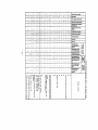
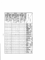
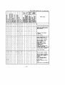
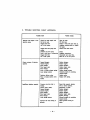
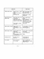
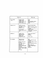
CHAPTER 4 TROUBLE·SHooTING..................................
59
Trouble shooting chart .•••. . • . . . . . . • • . • . • • . . . • • • • • . • • . • . . • . • • • ••
60
2 Trouble shooting chart (Appendix) •.• . • • . • • • • • . • • . • . • . . . . . . • • • . • . • . •• 64
CHAPTER 5 OVERHAULING INSTRUCTIONS
........................ 69
General instructions . . . . . . . . . . . . . . . . . . . . . . . . . . . . . . . . . . . . . . . . 69
2
3
4
5
6
Cylinder head and valves . . . . . . . . . . . . . . . . . . . . . . . . . . . . . . . . . . . . . 70
2·'
Reface of valve seats . . . . . . . . . . . . . . . . . . . . . . . . . . . . . . . . . . . ..
2·2
How to replace valve guides . . . . . . . . . . . . . . . . . . . . . . . . . . . . . . . . 70
2·3
Combustion chamber jet and director
2·4
Rocker shaft brackets . . . . . . . • . . . . . . . . . . . . . . . . . . . . . . . . . . . . 71
70
. . . . . . . . . . . . . . . . . . . . . . . . . 70
Pistons and connecting rods . . . . . • . . . . . . . . . . . . . . . . . . . . . . . . . . . .. 71
3·'
How to remove and install piston and connecting rod ass'y
3·2
How to ceuple piston with connecting rod
3-3
How to remove and install piston pins . . . . . . . . . . . . . . . . . . . . . . . . . 72
........... 71
. . . . . . . . . . . . . . . . . . . . . . 72
. . . . . . . . . . . . . . . . . . . . . . . . . . . . . . . . . . . . . . . . . . . . . . . . 73
Cylinders
4·'
Oversizes
4-2
Cylinder liners . . . . . . . . . . . . . . . . . . . . . . . . . . . . . . . . . . . . . . . .. 73
. . . . . . . . . . . . . . . . . . . . . . . . . . . . . . . . . . . . . . . . . . . . 73
Bearing metals . . . . . . . . . . . . . . . . . . . . . . . . . . . . . . . . . . . . . . . . . . . . 73
5·'
General cautions
5-2
How to assemble main bearing metals
5-3
Undersizes
. . . . . . . . . . . . . . . . . . . . . . . . . . . . . . . . . . . . . . . 73
. _ . . . . . . . . . . . . . . . . • . . . . .. 74
. . • . . . . • . . . . . . . . . . . . . . . . . . . . . . . . . . . . . . . . . . . 74
Timing gear . . . . . . . . . . . . . . . . . . . . . . . . . . . . . . . . . . . . . . . . . . . . .. 74
6·'
Timing gear train . • . . . . . . . . . . . . . . . . . . . . . . . . . . . . . . . . . . . . . 74
6·2
Valve timing . . . . . . . . . . . . . . . . . . . . . . . . . . . . . . . . . . . . . . . . . . 75
7
Oil seals
. . . . . . . . . . . . . . . . . . . . . . . . . . . . . . . . . . . . . . . . . . . . . . . . 76
8
Mountings
9
Oil pan installing
. . . . . . . . . . . . . . . . . . . . . . . . . . . . . . . . . . . . . . . . . . . . . . 76
. . . . . . . . . . . . . . . . . . . . . . . . . . . . . . . . . . . . . . . . . . 77
10
Oil pump
. • . . • . . . . . . . . • . • . . . . . . . . . . . . . . . . . . . . . . . . . . . . . . . 77
11
Water pump
12
Bolt screwing
. • . . . . . . . . . . . . . . . . . . . . . . • . . . . . . . . . . • . • . • . . . . . 78
• . . . . . . . • . . . . . . . . . . . . . . . . . . . . . . . . • . . . . . . . . . . 78
Model 40Q50 engine service standard ••..•••.••.•.•••...•..•.••.••• 80
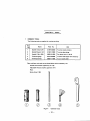
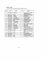
IiAPTER 6 TOOLS
........................................... 100
Common tools . . . . . . . . . . . . . . . . . . . . . . . . . . . . . . . . . . . . . . . . . . . . . 100
2
Special tools . . . . . . . . . . . . . . . . . . . . . . . . . . . . . . • . . . . . . . . . . . . . . 101
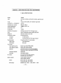
of APTER 7 MAIN SPECIFICATIONS AND PERFORMANCE . ............. 103
Main specifications of Mitsubishi Diesel Engine Model 40050
2
............ 103
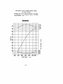
Performance of Mitsubishi Diesel Engine Model 40050 . . . . . . . . . . . . . . . . . 104
40050A (for motor vehicles) performance curve . . . . . . . . . . . . . . . . . . . 105
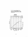
40050C (for construction machine) performance curve
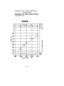
40050P (for general power) performance curve
. . . . . . . . . . . . . . 106
...........•....... 107
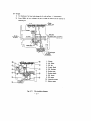
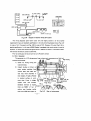
PREFACE
1.
In every new Model 40050 Engine, fuel injection pump and governor lever bear lead
seals that were put after their setting upon final confirmation of its performance through
test runs, at our factory. This service manual is intended to cover regular maintenance
services. For informations about particular servicing, especially of sealed units and parts
such as mentioned above, please contact our service man or your dealer.
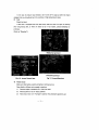
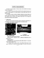
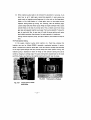
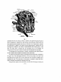
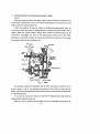
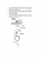
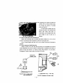
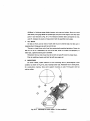
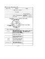
2.
Engine name plate is found on the up-side of rocker case. Engine Model and No. are
given on it.
They are also stamped on the right. side of crankcase. They will serve as important data
to know the engine's career and make-up of components.
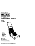
Fig. 0-1 Stamped engine No.
3.
Fig. 0-2 Service meter
As for fuel, engine's power source, and lubricating oil to smooth engine operation,
please use those are above OM class as shown in caution plate. Their choice has a
considerable influence on the engine's service life. Lubrication and other servicing in
accordance with the instructions given herein will promise its most satisfactory operation.
For regular service intervals are based on the reading of service meter, don't forget to read
it every day. At the same time, check the day's fuel and oil consumptions. The data
collected thus every day will prove very useful to know later how the engine has been
running and is at the time.
4.
We hope that, along with this manual, you will make use of the parts catalogue to
deepen your knowledge about the handling of your engine.
-1-
CHAPTER 1 OPERATION AND HANDLING
1.
NEW ENGINE
Prior to putting it in use, check as follows:
1)
See if there are any loose bolts or nuts.
2)
Lubricate according to Lubrication Table given later.
3) - Fill fuel tank with clean fuel and bleed (or prime) fuel system.
4)
Fill radiator with clean soft water as a ccolant.
When air temperature is expected to fall below the freezing point, use an antifreeze.
The service life of new engine much depends upon how it is handled in the initial
runs. So, lubricate, and check it with particular care (Refer to Lubrication and Service
Tables), and before it covers 60Hr, follow the instructions given below, taking care not
to overstrain it.
-2.
1)
After starting, never apply load immediately without warming it up well by idling.
2)
Don't run it at high speed.
3)
Run under some 70% of load at the maximum.
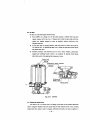
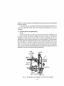
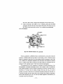
CHECKUP AND PREPARATIONS PRIOR TO
STARTING
Prior to starting the day's operations, check as
follows with the engine placed as level as possible.
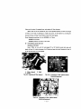
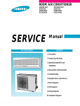
1)
Engine oil level
Pull out oil level gauge and wipe; then put it
in and out again to check oil level. Oil level must
be above mid-point between upper "FULL" line
and lower one. If near or below the mid·point,
refill up to upper line "FULL".
Oil level difference between these two lines
corresponds to approx. 1 litre.
After refilling, wait for all added oil to run
Fig. 1-1
Ch~king
oil level
down into oil pan and for oil level to settle, before checking it again.
2)
Cooling water level
Optimum -water level is 20'-30mm below the bottom of water inlet for pressure
type radiator, and up to overflow pipe for non-pressure type one.
Remarkable decrease of cooling water means leak somewhere, hence the necessity
to repair immediately.
-2-
In the case of pressure type radiator, don't screw off its cap just after the engine
stopped, lest you should get burnt by outblow of high-temperature steam.
3) Fuel
Check fuel level.
If fuel tank is equipped with fuel feed cock, make sure that it is open. At starting
after long leaving idle, or when air seems to be in fuel system, practise bleeding (or
priming).
(Refer to "Bleeding".)
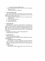
(Mechanical governor)
'pneumatic governor)
Fig. 1-3 Around-Stop lever
Fig. 1-2 Around Venturi lever
4.)
Power source
Make sure that battery switch and battery terminals are on.
Now check as follows and proceed to starting,
1)
That the engine is clutched off or free from load.
2)
That stop lever is not in "stop" position.
3)
That venturi lever is in "full-open" position (for pneumatic governor use)
-3-
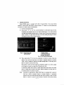
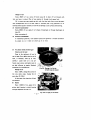
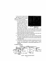
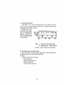
3.
ENGINE STARTING
Model 40050 engine is equipped with either of push button or key type starting
switches. In push button type switch, a press on button "H" keeps it on until another press
on button "5" makes it pop out automatically.
1)
Put key into starting switch.
2)
Press button "H" (or turn key counterclockwise) to make glow plugs red hot.
Pre-heating time depends upon air and engine temperatures. In any case, pre-heat
until glow plug indicator becomes red hot. Usually some 25 seconds pre-heating will
make it red hot. If it gets red hot too early or too late, check glow plugs, for that is
an evidence of one or more of them breaking.
1·
2
3
Fig.1-5
Fig. 1-4 Push button type
starting switch
3)
Starter switch
Glow plug indicator
Engine stop button
Key type starting switch
Then, press button "5" (or turn key clockwise) to switch on starter. When the
engine is very cold, pull stop lever at the same in opposite direction to position
"stop", and an increase of injection will make starting easier. In this case, pull it
back to "neutral" as soon as first firing.
Keep starter running until the engine has completely caught to run with a steady
rise of speed, but never any longer than 30 seconds at a time.
If starting has failed, don't switch on starter again before both starter and engine
come to a dead stop and starter cools down. While the engine is running, don't try
to increase injection nor switch on starter.
Note:
According to specifications, Model 400 Engine is equipped with a governor
that has a built-in automatic device to increase injection. In pneumatic
governor use, prior to starting, place stop lever once in position "stop" and pull
back to "neutral" to assure a quick increase of injection. Particularly attempt
-4-
4)
the same when the engine has stopped by chance.
When the engine has perfectly caught, bring back Venturi lever (or control lever)
immediately to "idling".
For starting in winter, Refer to "Cold starting".
4
,
AFTER THE ENGINE S START
Keep it idling at medium speed for some 5 minutes for
warm~up,
then start driving or
operations. This will prove very effective in protecting moving parts from wear and in other
aspects. With the engine idling, check as follows:
1)
Anything unusual with
~iI
pressure? (Refer to Par. 3-4, "Oil pressure", Chap. 3,
"Regular Servicing".)
2)
Does the engine make unusual noise?
3)
Is exhaust colour abnormal?
4)
Any leak of water, fuel or oil?
5 . ENGINE OPERATION
Model 4DQ50 engine is equipped with a pneumatic governor or a mechanical governor
for each use. This governor being of the all·speed governing type, variation of engine speed
depends upon how far Venturi unit is opened for in which position control lever is. This
design is such that, at a certain degree of Venturi unit opening or control lever position
engine output is automatically governed with changes of load so as to keep engine speed
almost constant.
During operation, leave stop lever in "neutral". (pneumatic governer 'use)
For details, refer to Par. 4-6, "Governor"
6
DURING OPERATION
After warm·up run, apply load on the engine.
During operation, judge how the engine is going, from
~e
indications of meters, sound,
exhaust colour and etc.
1) Oil pressure (Refer to Par. 3-4, "Oil pressure".)
Oil pressure gauge, if the engine is equipped with one, must read 3-4kg/cm 2
(2kg/cm 2 at minimum) at usual engine speed and above 0.5kg/crn 2 in idling. If oil
pressure alarm lamp attached, watch it every now and then. If it should get alight, check
oil system.
2)
Water temperature
Optimum range is 75°-85°C. Overheating arises from lack qf cooling water, loose
-
5-
fan belts and poor functioning of thermostat. In case the engine gets overcooled, put a
suitable cover on radiator.
3) 'Generator charge
While generator is charging batteries, ammeter pointer indicates (+) scale. At the
beginning of charging, it indicates about 10A, then gradually decreases as batteries get
charged. So you must not take this aspect for any generator trouble.
Charge pilot lamp, which is attached at option, goes out when the engine has
started and generator begins to charge. If a rise of engine speed should not put it off,
check and service charg'ing system immediately. If the system left defective, batteries
will entirely run down, making engine starting absolutely impossible.
7
STOPPING
After the operations over, let the engine idling for some 5 minutes. Don't bring it to a
sudden stop with its parts heated hot.
As letting it idling, pull back st:>p lever to position "stop", and fuel injection will be cut
off and thethe engine come to a stop.
When the engine has come to a dead stop, pull back stop lever to "neutral". Remember
that, if the lever released when the engine has not yet stopped, it may run reverse.
Note: Reverse running of the engine
Model 4oQ50 engine may happen, though rarely, to run reverse in the following cases.
1) When, in an attempt to cut off injection by pulling back stop lever, the lever is
released, before the engine comes to a dead stop.
2)
When starting motor is switched on with batteries not charged enough to power it
as required to start the engine.
Reverse running can be readily noticed, as the engine emits then much black smoke
through air cleaner, making noise at the same time. But it will rather hard to stop in
the usual way, for exhaust pressure will then' press govemor diaphragm so tight to
"full injection" pOSition as not to permit stop lever be easily pulled back.
So take any of the following emergency measures to stop it.
1)
2)
Bring accelerator button to "full-open" position and force back stop lever.
Increase load to maximum to bring the engine to stop. (Apply brakes, if
available.)
3)
Shut exhaust pipe by hand or with waste cloth.
Keep in mind that long reverse running will make oil pump run reverse, too, and as
the result, metals will get burnt from the stop of oil circulation.
-6-
8
HANDLING IN COLD WEATHER
When the air temperature is very low and the engine is cold, engine starting is
confronted with such factors as low temperature of intake air which disturbs the rise of
compression temperature, an increase of oil viscosity and a drop battery voltage which keeps
starter from developing enough power to drive the engine. In addition, cooling water and
battery electrolyte may freeze up. For starting and handling in cold weather, follow the
special instructions given below.
8-1 Starting in cold weather
Proceed according to the following additional hints so that a single attempt will
make success in starting. Repeated use of starter will discharge batteries.
1)
Put the engine as free from load as possible. If clutch attached, disengage it,
besides shifting transmission gear into neutral.
2)
Pre-heat well by electrifying glow plugs for 30-40 seconds, so as to permit
ready ignition. If starting has failed, don't switch on starter again without
pre-heating.
3)
The moment first firing takes place, bring back lever to neutral. Further
increase of fuel feed will cool combustion chamber, hence a lag in perfect
firing.
4)
Even when initial ignition has taken place and .been followed by imperfect
combustion, keep starter running until the engine perfectly catches to gather
speed, so that glow plugs will remain red hot to help perfect firing. Starter has
a free wheel, which protects it against any damage even when its pinion is kept
in mesh with ring gear in that way. In any case, don't run it any longer than 30
seconds at a time.
8-2 General instructions
1)
Unless an antifreeze is mixed in cooling water, drain it off entirely after the
operations over, lest it should freeze up to damages cylinder block, cylinder
heads, radiator, etc.
Use of an antifreeze dispenses with the trouble of draining.
Choose a reliable brand of antifreeze that contains a suitable proportion of
anticorrosive, and mix it according to the manufacturer's instructions given on
the can, for its proportion usually depends upon the lowest temperature
expected. Quantity of cooling water for 4DQ50W is 10 litres and 40Q50C is
16 litres. (with standard radiator)
2)
In winter, use engine oil of lower viscosity. (Refer to Chap. 2, "Engine Oil".)
3)
Existence of water in fuel will cause some trouble with fuel system from
-7-
freezing of pipes. So bleed (or prime), fuel tank, fuel filter, etc.
4)
At low temperature, battery capacity goes down, hence batteries should be
covered with a tarpaulin sheet, or be stored in a warm place when not needed.
Keep the specific gravity of battery electrolyte' above 1.25 so as to prevent it
from freezing. (Refer to Par. 6-4, "Batteries" Chap. 3).
5)
Warm up the engine well, and never overstrain it.
During operation, watch thermogauge and if it gives any sign of overcooling,
put a cover on radiator.
9
HANDLING IN THE HOT SEASON
1)
Use engine oil intended for summer. (Refer to Chap. 2, "Engine Oil".)
2)
Keep the tension of fan belts properly adjusted so as to allow them a slack of
12mm. (Refer to Par. 5-3 "Tension of fan belt" Chap. 3) Watch thermogauge, too.
When cooling water has started boiling from overheat, Don't stop the engine at
once, but let it idling for a time, Waiting for water temperature to fall.
3)
Check battery electrolyte level every day and if lower than specified, add distilled
water.
4)
When the engine is to be left idle under high temperature for several days or longer,
store batteries in a cool dark place to prevent their self-discharge.
-
8-
CHAPTER 2 FUEL, OIL AND COOLING WATER
1
FUEL
1)
For fuel, use gas oil (with greater cetane number than 45) of a well-known and
reliable brand and destined for high"speed Diesel engines.
2)
Use of clean fuel is of greatest importance for the fuel system of a Diesel. Dust and
water in fuel do damage to precisionmachined injection pump, nozzles, etc. In
filling fuel tank, take care not to let in any bit of dust and water. The refilling of
fuel tank should be done after the operations are over. At regular intervals, open
drain cock on fuel tank to draw off settled water and dirt prior to starting, and
wash its interior.
2
ENGINE OIL
2-1 Quality required of engine oil
A high-speed Diesel requires for its lubrication better-quality mineral oil than that
intended for ordinary gasoline engines.
It means that such oil satisfies the following requirements.
1)
To be stable against heat and oxidation.
By high heat of cylinders, oil is subject to oxidate and carbonize, and
cor.sequential collection of carbon and residues leads to wear and seizure.
Therefore, oil needs to contain at least two kinds of additives to improve its
stability; an anticorrosive and a detergent that dissolves carbon and sludge in
oil and thus washers them away.
From these view-points, use always H.D. type that contains both, so is very
favourable for the service life of pistons, liners, rings and metals, etc.
2)
To have high viscosity stability against changes of temperature.
For easy starting at low temperature, oil is required to be low in viscosity but,
after starting, be high enough to assure perfect oil film on
high~temperature
parts. Practically, however, a single oil cannot opportunity satisfy these
requirements, so it follows that an oil whose viscosity is less subject to change
should be used.
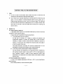
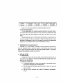
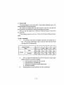
2-2 Recommendable classes of engine oil
In view of the foregoing requirements, DM class in A.P.I.'s service classification
should be chosen.
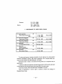
As for viscosity selection, consult the following table.
-9-
Climates
Above 40°C
40° -_5°C
_5° - _15°C
Below-15°C
Viscosity
SAE #40
SAE #30
SAE #20
SAE#1aw
Except in an frigid region, SAE 30 can be applied throughout the year.
2-3 Time to change engine oil
Time to change engine oil is indicated as a general standard in Lubrication Table. It
may, however, get dirty and deteriorate very soon and need to be changed much ahead
of the given time, under some conditions of use, and be very show to do so under
others.
Practically speaking, the user himself should judge whether it can stand further use
or must be changed. For this, we recommend a simple test called "spot test", where
some drops of used engine oil are put on filter paper to see how far it has deteriorated
and got dirty. For details about this test, ask the manufacturer of the oil.
3
DIAPHRAGM OIL (Pneumatic Governor)
Diaphragm oil is a kind of leather oil intended to prevent the aging or deterioration of
sheep skin diaphragm placed in pneumatic governor of fuel injection pump, and to keep
governor action smooth and sensitive. Use always those brands indicated on· Lubrication
Table, and never substitute by engine oil (mineral oil).
4
COOLING WATER
4-1 Required quality
Cooling water must be clean and soft. Never use any water that contains salt or is
near a mine or a spa, because it will scale hard water jacket and corrode cylinder liners
along their outer circumference.
4-2 Handling of cooling system
1)
In leaving the engine idle for many hours, especially in cold weather, open all
drain cocks to thoroughly drain off cooling water.
2)
When the engine has overheated and has been empty of water, never pour cold
water in radiator.
3)
For the use of an antifreeze, refer to Sect. 8, "Handling in Cold Weather"
Chap. 1.
-
10-
CHAPTER 3
REGULAR SERViCING
To service your engine regularly is the key to enjoy its ever trouble-free and efficient
operation and long service.
To say nothing of usual services before and after the work, appropriate measures must
be taken if, during operation, any unusual symptons in sound, exhaust colour, smell, etc.
should be noticed.
In this chapter are given in detail the necessary instructions for regular checkup and
servicing, starting with lubrication, along with the constructional descriptions of engine
parts. Standard intervals are based on the reading of service meter. For any ch&ckup and
servicing, place the engine as level as possible.
1
LUBR ICATION
This section covers the points of lubrication, which is a basic factor of maintenance. It is
most desirable to use the classes of oils recommended in the preceeding chapter.
'j)
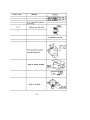
Engine oil pan Checkup of oil level:
1
Drain plug
Fig. 3·2 Drain plug on oil pan
Fig. 3-1 Checking oil level
Check it every morning or prior to starting.
Checking procedure is described in Sect. 2, "Checkup and Preparations prior to
Starting", Chap. 1.
Change of engine oil:
Every 250Hr of run, or when bypass alarm has got alight, change oil. In new engine,
change it after initial 60 Hr of run.
For complete change of used oil, drain it off, screwing off drain plug on oil pan
while it is still hot, i.e., a little after the engine stopped. At the same time, empty oil
-11-
filter and oil cooler (if attached) too, and replace oil filter elements.
When used oil has all drained off, pour in the specified quantity of new oil through
oil filler on the side of crankcase. or rock.er case cover, let the engine run at idling for
several minutes, and stop it and check oil level with level gauge.
Note: Standard quantities of oil for ·400SOW is 4.7 litres.
40OSOC is 6.0 litres.
400S0P (without oil cooler) is 6.7Iittes.
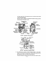
2)
Fuel. injection pump cam case
Chockup of Oil level:
Every 120Hr of run, pull oil level gauge (1) out of injection pump cam case and
check oil level. If it tells a decrease of oil. Check and repair the leak. Standard oil level is
up to the mark line cut on the gauge.
1. filter element 3. Head
2. Coyer
Fig_ 3-3 Replacing oil filter element
Fig. 3-4a Lubrication of fuel injection pump
(pneumatic governor)
Fig. 3-4'b Lubrication of fuel injection pump
(mechanical governor)
-
12-
Change of oil:
Every 250Hr of run, screw off drain plug (2) to drain off oil thinned with
fuel, and pour in about 70cc of new engine oil through level gauge hole.
Oil in pump cam case usually get thin with fuel that leaks from around plungers,
and consequential rise of its level makes it overflow pipe. Long operation on oil
thinned almost equal in viscosity to fuel wil! do damage to cam surfaces and bearings.
3)
Governor (pneumatic)
Every 250Hr of run, apply 3 to 5 drops of diaphragm oil through diaphragm oil
hole (3).
Never use engine oil.
4)
Governor (mechanical)
In mechanical governor, fuel injection pump and governor is forced lubrication
by engine oil, so it need not check up of oil level.
5)
Air cleaner (with oil bath type)
Check up of oil level:
Keep to the optimum oil level in
the oil bath. Every 60Hr check up of oil
level, if necessary refill up to "01 L
LEVEL". Lower level oil is not sufficient clean action and higher level oil
act bad influence to engine. Standard
quantities of oil is 0.85 +itres.
Fig. 3·5 Change of oil in the
oil bath type air cleaner
Change of oil:
Every 120Hr, change the oil. But in
the· very dusty areas, change the oil
every day. (5-10Hr)
At the same time clean the oil bath
and element.
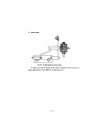
6)
Starter
Every 1,OOOHr of run, apply oil to
pinion shaft bearing in clutch housing
through respective oil holes. (1).
Fig.
-
13-
3~
To apply oil to starter
7)
Tension pulley
Fig.3-7 To apply grease to tension pulley
If engine is no need of dynamo, tension pulley is equipped. Tension pulley has a
grease nipple (Fig. 3-7), every 250Hr of run apply grease to it.
-
14-
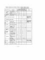
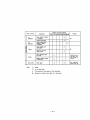
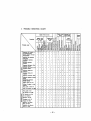
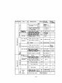
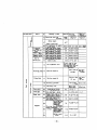
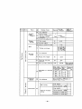
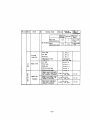
Lubrication Table for Model 4D050 Engine
Items
Description
Change oil
Injection pump
cam case
(Pneumatic)
120Hr 250Hr 500Hr 1000H
*
Change oil
::)
()
70cc
()
Change oil
Air cleaner
(With oil bath
type)
Remarks
At the same
Refer time,empty
Chapt oil filter
and replace
3
fi Iter elements
E.O
E.O
Apply oil to
diaphragm
Q'ty
v
Check oil level
Governor
(Pneumatic)
0.0
Check oil level
E.O
<)tarter
Apply oil to
bearing
E.O
Tension pulley
Apply oil to
bearing
G
Note:
60Hr
~,
Check oil level
Engine oil pan
Lub. Intervals
Lubri·
cants Daily
0
3-5
0
0.85.0
drops
v'"'
0
0
0
Several
drops
,.....
v
1. Marks
.... : Generally
o : In
very dusty areas
* : First service for new or overhauled
engine
2. Symbols
E.O : Engine oil
0.0 : Diaphragm oil
3. Mechanical governor is forced lubrication by engine oil
2
AIR SYSTEM
2-1 Air cleaner (oil bath type)
Model 40Q50 engine is equipped with either of oil bath or filter paper type air
cleaner. Oil bath type air cleaner consists of centrifugal type pre-cleaner and oil bath
type cleaner.
1)
Quaritities of oil and change of oil refer to "Lubrication".
-
15-
2)
Pre-cleaner gathers comparative
3)
Oil bath gathers comparative
Pre· cleaner
parge dirt.
small dirt. If the oil is not
fluidity by very small dirt,
change the oil in spite of the
existence
of
sediment and
servicing interval.
4)
For washing the oil). At the
same time wash the lower
element.
5)
Element
Be care not to tamper the air
cleaner . during engine operation.
6)
Oil level
Be care not to leak from
connecting pipe. If the dirty air
enter the cylinder, it injur the
Oil bath
valves and cylinder sleeves, and
Fig.3-8 Air cleaner (Oil bath type)
in the case of pneumatic governor use, it gives bad influence to the governor
action.
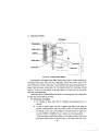
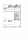
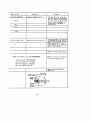
2-2 Air cleaner (Filter paper type)
In filter paper type air cleaner, paper element performs an important part. In
handling, be very careful not to rub or scratch its surface. If scratched or damaged even
a bit, replace with a new element.
A thin pipe from the case is connected, with a vinyl tuve, to diaphragm air chamber
in pneumatic governor. (Refer to Par. 4-6, "Governor".) Keep this tube firmly
connected. If off, it will let in dust.
1)
Every 2S0Hr of run, take out element
to
clean by blowing air from inside. At
the same time, clean the interior of case. If compressor not be available tap
element clean of dust. Never wet it with water. When the engine used in a very
dusty place, do the cleaning at shorter intervals.
2)
Every SOOHr of run, replace element with new one.
-
16-
II~
=
I
.:~
I
Case packing
Cleaner cover
Wing nut
Cleaner case
Element
Fig. 3·9 Air cleaner (filter paper typel
'- 17-
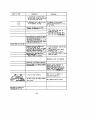
2-3 Valve clearances
Both lack and excess of valve clearances affect engine performance. Especiallyexcessive valve clearances will induce much strain. on valve mechanism, making the
engine subject to serious trouble.
Apart from regular checking required every 2S0Hr of run, check and adjust them
whenever low-speed running of the engine makes any unusual sounds. For new Engine,
adjust them when it has run for 60Hr. Proper clearances are, exhaust and inlet valves
alike, O.2Smm as measured in cold (or uniformly warm) engine.
Firing order is: 1-3-4-2.
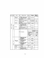
2-4 Compression pressure
1)
To see whether or not intake air into cylinders undergoes there sufficient
compression with no blow-by to help the firing, measure compression pressure.
2)
The results will tell if:
a) Valve seats are in tight enough contact.
b) Cylinder liners and piston rings are not worn or sticking hard.
c) There is any leak of gas ascribable to other cuases.
Regular measurement at intervals of about SOOHr of run will provide reliable data
to decide when to overhaul the engine.
3)
Prior to measuring it, check
and adjust valve clearances so
that rockers do not press down
valves in compression stroke,
and make sure that Venturi
butterfly valve is full open.
4)
Standard compression pressure
is above 20kg/cm 2 at an engine
speed of 1S0-200 r.p.m., and
with oil and water temperatures in a range of 20°-30°C.
Fig.3-10
Adjusting valve clearance
Please have it measured by your dealer or at a service shop.
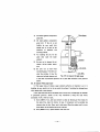
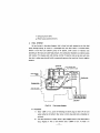
3
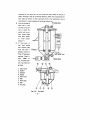
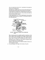
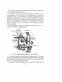
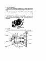
OIL SYSTEM
As can be seen in circulation diagram (F ig. 3-11), lubrication system is forced
lubrication by a trochoid oil pump. At option, a water-cooled oil cooler is equipped between
oil pump and oil filter to keep oil in an optimum temperature range.
-
18-
3-1 Oil pan
1)
2)
For checkup of oil level and change of oil, refer to Sect. 1, "Lubrication".
Every 500Hr of run, unfasten oil pan to wash its interior and oil strainer in
cleansing oil.
r-:-?"~-~-'. .-.. -
ROCker
....
.
.
.
.
;
:nlr---J
•
I
Piston
1. Piston
2. Oil Filter
3. Oil jet
4. Crank Shaft
5. Oil Strainer
6. Rocker-arm
7. Rocker-shaft
B. Oil alarm
9. Oil pump
10. Injection pump
11. Water pump
Fig. 3-11
Oil circulation diagram
-
19-
3-2 Oil filter
Oil filter is of the filter paper full-flow type.
1)
Every 250Hr run, change oil. On the same occasion, unfasten filter case and
replace element with new one. If bypass alarm lamp has got alight with the
engine hot, replace element as soon as possible, without sticking to the
standard intervals.
2)
At the same time to replace element, wash the interior of filter case in gas oil
(or cleaning oil). In assembling again, don't forget to place spring and spring
seat where they were.
3)
Carefully examine used element and oil and if many metallic, particularly
copper-color settlings found, which is an evidence of bearing metals being
abnormally worm, take appropriate measures at once.
Center bolt
Spring
Differential alarm terminal
Element
Fig. 3-12
Oil filter
3-3 Differential bypass valve
This valve is set in oil filter cover. The design
i~
such that an oil pressure difference
2
above 1.5kg/cm between inlet and outlet sides of filter element arisen from its being
choked with dirt makes it open to bypass unfiltered oil directly into main oil· gallery in
-
20-
order to prevent any serious
trouble,
Differential bypass valve (Yflth switch)
seizure
for
ex-
ample, that might be caused
r--~:r-...,
FROM OIL PUMP __
=~~J
TO MAIN OIL GALLERY
-"""'
by lack of oil. Whenever the
valve set to perform so, of
~ Relief
which the operator will be
valve
J
signalled by alarm lamp in
TO OIL PAN
Fig. 3-13
front of his seat, element
must be replaced at the
Oil flow diagram
earliest possible opportunity, for lubrication with unfiltered oil will affect moving parts.
The above alarm tamp is set alight, as soon as the valve opens to perform such an
emergency bypassing, by contactor that is attached to it for that purpose.
3-4 Oil pressure
Under ordinary weather conditions and at usual engine speed, oil pressure is kept
between 3 and 4kg/cm 2 by relief valve on oil filter cover. (The lowest permissible
pressure is 2kg/cm 2 ). Model 40Q50 engine is provided, at option, with either an oil
pressure gauge or an oil pressure alarm switch (which puts alarm lamp alight at a drop
below O.5kg/cm 2 ).
1)
Under the following conditions, oil
pressur~
often goes out of the given range,
but will usually become normal as the engine is run.
a) When the engine has not yet warmed up, i.e., soon after its starting. In this
case, oil pressure goes, above the standard range, claiming for its good
warm-up through low-speed idling.
b) When, after a warm-up, the engine is let to idle, oil pressure drops low. But
this means nothing wrong so far as it remains above O.5kg/cm 2 •
2)
Any other drop of oil pressure than incidental to the above case will lead some
serious trouble; hence the necessity to check as follows and take necessary
measures.
a) Is oil level high enough? It must be above lower mark line' on oil level gauge.
b) Anything is wrong with oil presSure gauge and its piping?
Check also alarm switch and lamp, measuring oil pressure with an oil pressure
gauge.
c) Any leak in oil line? Other probable causes are:
d) Oil pump suction-side piping is inhaling air.
e) Bearings worn down.
-
21-
f) Oil pump worn down.
g) Relief valve covered with dirt.
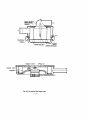
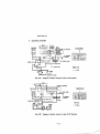
4.
FUEL SYSTEM
As can be seen in the above diagram, fuel is, from fuel tank, pumped up by fuel feed
pump through piping, by which it is discharged into fuel filter where it is filtered clean;
thence is runs into fuel injection pump to be ejected, under control of injection rate
according to the load and under high pressure, into combustion chambers via injection pipes
and nozzles. For
stop~ing
and cold starting, control of injection rate can be done with stop
lever but in other cases, should be left to pneumatic governor that works by Venturi negative
pressure.
Fuel injection pipe
7?:;?;:~r;=;;=f=;~F==~ ,~,t',F"'1 injection nozzle
FUE~RETURN
Fuel injection
BiNding plug
Pump
Fuel filter
Overflow pipe
BiNding plug
Fuel fHd pump __
~
n
)':1
i
t
'-"-".:
\
:
LJ
L ___.-J
-"1
Fig. 3·14
Fuel system diagram
4·1 Fuel filter
1)
Every 120Hr of run, screw off bleeding and drain plugs to drain off dirt and
water settled at its bottom; then screw in drain plug and make a bleeding (or
priming).
2)
Fuel filter element is of paper. When it gets clogged with dirt, fuel feed makes a
drop. Replace it with a new element every l,OOOHr of run. To wash it in
-
22-
cleansing oil will remove dirt on the surface but surely affect the texture of
paper, involving a drop of its filtering efficiency. When filter disassmebled for
that, wash the interior of filter case clean of dirt. After assembling it with a
3)
new element in, make a bleeding (or priming) without fail.
Bleeding plug
Joint on the side of
filter case is inlet
and that on its bottom is outlet. Be
careful not to connect wrong pipes
with them. (Refer
"Fuel
to
system
diagram".)
4)
In
inlet joint of
fuel
feed
pump
that connect pipe
from fuel tank is
~
placed a strainer to
Spring
filter off large dust
particles. Clean it
every
120Hr
of
¢=
run. If choked with
dirt, fuel feed will
go down.
1. Filter cover
2. Gasket
3.
4.
5.
6.
7.
Element
Spring
Filter case
Bolt
Drain plug
B. Bolt
9. Air plug
Fig. 3-15
Fuel filter
- 23-
4-2 Bleeding (or priming)
If air should get in fuel system, injection will go wrong, keeping the engine from
steady running or making it difficult to start. So, whenever any servicing done with this
system, bleed (or prime) it in the following procedure.
1) Loosen bleeding plug on fuel filter and move hand pump on fuel feed pump up
and down.
As fuel filter is fed full with fuel, air bubbles will run out with fuel through
bleeding plug. When the outflow of fuel does not contain air bubbles any
longer, screw bleeding plug tight.
2)
Loosen bleeding plug on the top of injection pump, and move hand pump
3)
With nozzle-side cap nuts
like-wise up and down to eliminate air out of fuel pump in it.
~n
injection pipes loosened and stop lever in
"full-open" position, run run the engine scores of revolutions by -starting
motor, and all four injection pipes will be bled of air at a time.
The bleeding must be done, too, when the engine has been left idle for a long
time, fuel pipes replaced, or nozzled checked.
Fig.3-16 Joint on fuel inlet in fuel feed pump
Fig. 3-17
Bleeding fuel injection pump
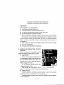
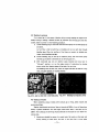
4-3 Checkup of nozzles
When something unusual notices with exhaust gas or firing, check nozzles and
service accordingly.
Regular checking and servicing of them at intervals of 500Hr of run will keep them
always in perfect conditions. For new engine, check them when it has been run for
250Hr. Their checkup and serviCing should preferably be entrusted to your dealer or a
xervice shop.
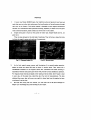
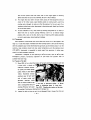
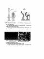
1)
Nozzles are checked by means of a nozzle tester. Set nozzle on the tester and
slowly pressing its hand lever, see how it will eject fuel. It must !flake
-
24-
Fig.3-18
Testing nozzle
Fig.3-19
Main injection from nozzle
intermittent injection in fine spray with sharp hisses. Spray must not split at
the end, nor go astray, nor dribble.
2)
See also at what pressure it will start injection. It must be within a range of
120±5kg/cm 2 • Any discrepancy is corrected by changing the total thickness of
shims on nozzle spring with nozzle nut off. For the calculation of how much
shims must be added or removed, remember that 0.1 mm of thickness
corresponds to approx. 10kg/cm 2 of injection pressure.
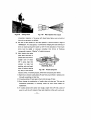
3)
Main injection that takes
place when hand lever is
pressed hard must form a
straight cone of about
40° in spray angle that
contains no large fuel
particles, and. must break
clean off without leaving
Fig. 3-20
any drop of fuel around
Nozzle spring shim
injection orifice. In handling nozzles, follow the instructions given below.
1) Each time to remove nozz·les,clean off dust from around them in advance, lest
it should on packings on their tips.
2) In leaving nozzles off, put caps on their inlets to keep off dust.
3) Never change the combination of needle valve and valve se.at. This must be
remembered particularly in removing nozzle tip from nozzle holder for
replacement.
4) If nozzles stained with carbon and sludge, scrape them off with a piece of
wood or such·like soft material. Never pick injection orifices with a wire, etc.
-
25-
5) To service nozzle tips, wash them well in clean cleansing oil, carefully fit
valves onto their respective seats in oil and after washing them clean once
more, put together in clean gas oil. Never wipe them with waste cloth, etc.
6) Nozzles usually let a little fuel go back. Excessive increase of return fuel is an
evidence that they must to replaced with new ones.
7) To install nozzles, clean off carbon from nozzle seat packings, but be careful
not to scratch or otherwise damage seats. Any seat notably sunken in the
surface must be replaced, for it will spoil air-tightness of cylinder even if
clamped down tight. To install, screw nozzles by about 5kgm of clamping
torque. To strain them.
4-4 Fuel injection pump
1)
For checkup of oil level and change of oil, refer to Sect. 1, "Lubrication".
(Mechanical governor is forced lubrication by engine oil, so it need not check
up of oil level and change of oil)
2)
Being precision-machined and adjusted like nozzles, injection pump will not
require any particular adjustment but at the time of over-hauling, it should be
thoroughly adjusted by means of a pump tester. If anything unusual noticed
with it. have it examined and if necessary. serviced by your dealer or at a
service shop. In such a case that. nozzles having nothing wrong at all.
combustion does not go well in any of cylinders. check as follows.
a) With the engine running, loosen either cap nut on one injection pipe after
another. So you will fined the cylinder from which the symptom comes. Such
symptons come from. for example, the following causes.
b) Set screw on pinion is loose. In this case. injection rate is out of perfect
control, that is to say. not varying exactly in conformity to control rack
travel.
c) Plunger spring is broken.
d) Delivery valve spring is broken. To inspect it. loosen delivery valve spring.
Broken spring keeps injection from breaking clean off for poor sucking back
of fuel.
Inspect the contact of delivery valve seat. too. If badly worn or otherwise
defective. pull it out to replace by means of a special tool intended for that. In
putting together again. attach a new gasket to valve so far as
possi~le.
In these
operations. take every possible measure to keep off dust. Remember that valve
holder must be screwed exactly to 3.5kgm of clamping torque
wrench..
-
26-
wit~
a torque
3)
When injection pump needs to be removed for adjustment or servicing, try to
learn how to set it right again, memorizing especially in what relation the
match mark on injection pump flange part is to the mark on the flange plate.
(Refer to Fig. 3-22) Before it is fixed again, never run the engine lest the
injection timing should go wrong. For removing, take the follwoing steps.
Loosen clamp bolts that fasten pump flange to engine crankcase with a socket
wrench fitted on the end of universal joint. Then, unfasten cover from timing
gear case and separate injection pump gear from pump camshaft. To leave the
gear in mesh with idler in gear case will make the pump setting much easier
don't c!isjoin autotimer from the gear, for easier operation in installment.
Having removed injection pump, put caps on delivery valve holders to keep off
dust.
4-5 Fuel injection timing
In this engine, injection pump starts injection at a fixed time, whatever the
injection rate may be. Model 40Q50 is attached a mechanical autotimer in option,
which is coupled with injection pump gear, varies the injection starting time according
as the engine speed changes and thus provides always the fittest injection timing. This
injection pump is fastened by means of flange so that injection starting time can be
varied by changing its setting angle. The pump having been adjusted right to the values
and firmly fixed at our factory, the injection starting timing will never to wrong.
Fig. 3·22
Fig. 3·21
Timing mark on crank
shaft pulley
-
27-
TIming mark on flywheel
In the case that the injection starting
angle needs to be newly set for such
reasons as replacement of the injection
pump with a new unit, do as follows.
1)
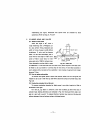
First locate the top dead center of
#1 cylinder compression stroke,
turning crank shaft. For this, turn
crank jaw with a wrench if it
permits easy access of hand, or
ring gear by a tooth after another
TIming mark on
injection pump
Fig. 3-23
with a screw driver, if it does not.
Go on turning it until symbol T on crank shaft pulley or symbol 1.4 on
flywheel exactly meets the pointer, and #1 cylinder piston will be at top dead
center. But assuring this, open rocker case cover and make sure that both #1
cylinder inlet and exhaust valves keep proper clearance.
2)
With #1 cylinder piston thus placed at top dead
cente~,
read at what crank
angle injection will start. For this, take the following steps.
3)
Loosen off #1 cylinder injection pipe so that a little fuel remains in the upper
part of delivery valve holder. Slowly turn crank shaft in its usual direction (that
is, clockwise as viewed from fan), and fuel level will start swelling. Read crank
angle at that moment.
4)
In case injection timing needs to be set ahead, move injection pump body little
by little in the reverse direction that its camshaft revolves (or toward
crankcase). Note that graduations on pump flange corresponds each to SO of
crank angle.
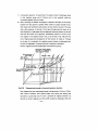
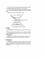
4-6 Governor (pneumatic)
DIARHRAGM
AIR PIPE
¢=
,.....,.,.......~
FULL LOAD STOPPER
INLET VALVE
NEGATIVE PRESSURE
CHAMBER
Fig. 3-24
Scheme of pneumatic governor
-
28-
_ _ AIR INLET
1)
A pneumatic governor, for governing of its speed, consist of diaphragm block
in fuel injection pump and of Venturi unit in inlet manifold, which are
connected together with an air pipe.
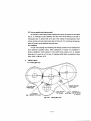
2)
Now, following the scheme and diagram of operation principle, we will briefly
explain how this governor operates. When intake air passes through Venturi
that closes inlet manifold to some extent, its flow velocity rises but at the same
time, static pressure at that part (to be taken through pipe that opens to its
flow direction at a right angle) falls considerably below the pressure on the area
free from the inflow of air (generally, atmospheric pressure) or in short, turns
into negative. This negative pressure rises, as can be seen in Fig. 3·25, with the
rise of engine speed and consequently of flow velocity of intake air. Through
an air pipe, it is conducted into negative pressure chamber in diaphragm block
to work on diaphragm. The governing force it produces is calculated:
(Venturi negative pressure)x(Diaphragm area)=(Governing force)
Diff.,....ti .. ~. ~
both sides of di'-'ecm by
Yenlui necativo Pr_L
Openi"l in idlinl
Main sprinC
.:tian
r..,~.~~:::t=====t=:j===:;~=;;~::;'"
Fig. 3·25
Diagramatized principle of pneumatic governor operation
Now suppose that max. engine speed needs to be governed at A (rlp.m.). While,
with Venturi butterfly valve opened 100%, main spring with setting load
equivalent to governing force Fc that is produced by negative pressure C at
point B on Venturi negative curve (Fig. 3·25) is placed on diaphragm. When the
-
29-
engine tries to run at a higher speed than A (r.p.m.), a consequential rise of
negative pressure provides greater governing force, which compresses main
spring against its setting load, thereby pulling back injection pump control rack
to reduce injection, and as the result, engine speed is slowed down to A
(r.p.m.). When, on the other hand, engine speed is made to fall below A
(r.p.m.), a decrease of negative pressure lets main spring press control rack
ahead to rise injection rate, whereby it is vised back to A (r.p.m.). Meanwhile,
the more Venturi butterfly valve throttles, the quicker rise of negative pressure
to engine speed can make engine keep low constant speed, by producing
governing force Fc. Governing the engine speed thus in one-to-one proportion
to the percentage of Venturi opening, this governor is called an all-speed type.
In case heavy load on the engine makes it run at a lower speed than equivent to
the Venturi opening (for example, lower than A even at 100% of Venturi
opening, in the diagram), control rack is pressed over its whole travel to full
load stopper, making it to develop max. torque. If "tough" torque is required
of the engine, governor is equipped with a buitin torque spring (angleich
spring).
3)
This type of governor requires espeCially perfect air-tightness of air pipe and
intake system, for lack of their air-tightness will much affect its performance
and cause particularly overrunning.
Into air chamber for atmospheric pressure in diaphragm block negative pressure
is lead from inside paper element of air cleaner through vinyl tube so as to
compensate the change of resistance the might arise from its clogging.
4)
Being of sheep skin, diaphragm in diaphragm block requires regular lubrication.
(Refer to "Lubrication".) When a sudden unusual change noticed in idling,
have it checked by your dealer or at a service shop, as it is suspected to be
broken from aging.
Each time to apply oil to diaphragm, loosen red plug ~n the side of diaphragm
block to draw off the excess of diaphragm oil or fuel collected there from
pump. If too much fuel found there, make necessary repairs.
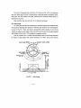
5)
In any case whatever, don't tamper with the seals on (Fig. 3-26, 3-27)
I njection pump full load stopper Seal
Diaphragm block cover Seal 2
'Idling sub-spring Seal 3
Venturi lever stopper ("full-open" side) Seal 4
-
30-
Fig. 3-26
Diaphragm block of governor
Fig. 3-27
Venturi unit
4-7 Governor (mechanica/)
1)
Model 4DQ50 Engine is equipped, for governing of its speed, with mechanical
governor (centrifugal type) which connected directly with fuel injection pump
camshaft.
This governor is RUV and all-speed type, so it controls not only max-min
engine speed but also can control every engine speed by control lever position.
2)
As mechanism illustrated Fig. 3-28, two flyweight combined with governor
shaft and rotates through the gear which equipped with camshaft, and
centrifugal force of weight conducts to the governor sleeve.
In the governor sleeve, angleich spring is equipped. Centrifugal force of
flyweight and control spring force act to this spring, so it works as angleich.
Control spring is installed to the adjusting lever's shaft and one end of spring
put to the spring seat. Control spring force changes by this lever's motion.
The lower parts of floating lever is ·combined to supporting lever and this
position is determined by full~load stopper.
Sliding peace, which is equipped in the middle of the floating lever, inserts
governor sleeve groove and works with movement of sleeve, and move the
control rack which connected with upper parts of the floating lever.
The arm, which connects floating lever and control rack, is equipped with start
spring and one end of spring is connected with governor housing.
This spring always pull the control rack to the fuel feed "increase" and increase
of fuel feed at starting. In the case of torque spring equipped, torque control
lever is installed, and upper parts of lever touch to the torque spring adapter,
-
31-
and lower parts touch to the spring seat and act to reduce the control spring
force by torque spring force.
Stop lever, which is installed to the upper parts of governor housing, pull back
the control rack to the position "stop".
Stop lever shaft
Oil inlet
Floatiag lever
Bearing bushing
Fig. 3·28
Mechanism of RUV governor
Torque spring
Control spring
Supporting point B
Start spring
Floating lever
Camshaft bushing
Slip disk
Spring seat
Angleich spring
Governor sleeve
Flyweight
Full load stopper
Supporting lever
Stopper
Supporting point A
Stopper bolt
Fig. 3-29
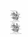
3)
RUV governor, movement of idling
Fig. 3·29 shows the situation of idling. Flyweight, though it is lower speed,
expand to the outside by centrifugal force, overcome weak spring force and
push the governor sleeve to the right hand with spring lever.
Therefore floating lever's supporting point (B), which touch to governor sleeve,
-
32-
move to the right hand as lower part (A) is supporting point and pullback the
cont~ol
rack to the idling position.
Centrifugal force of flyweight, weak force of control spring and spring force of
start spring act each other and keep the smooth idling by this force balance.
As efjgine speed rise, centrifugal force of flyweight becomes large and push the
contrpl spring and floating lever moves to the right hand, and transfer the
contrpl rack to the fuel feed "decrease".
As engine
SP~
becomes to fall, it acts the opposite action of above and keep
the constant idling by this action and reaction. Fig. 3-30 shows the situation of
max. !!ngine speed control.
Camshaft bushing
Stopper bolt
Fig.3-30
RUV governor, movement of max. engine speed
control
When the engine speed rise from regulation speed by the rapid down of load
while the engine running, centrifugal force of flyweight overcome the spring
force of control spring, and flyweights expand to the outside and move the
gover.,or sleeve to the right hand. (as illustrated arrow mark) At this time
supporting point (8) of floating lever, which contact to the governor sleeve,
move lO the right hand as (A) is supporting point.
Therefore it moves control rack to the fuel feed "decrease" and acts not to
over the regulation max. speed.
4)
In any: case whatever, don't tamper with the seals on (Fig. 3-31),
-
33-
Injection pump full load stopper
Seal 1
Torque spring Seal 2
Fig. 3-31
RUV Governor
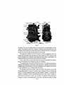
--------------*GOVERNOR (Model RSV,bosch type)
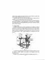
(1) STRUCTURE AND OPERATION
Fig. 1 is the open·up view of the sectioned governor and its parts and Fig. 2 shows the
disposition of such patts.
. In the RSV type Mechanical AII·speed Governor, the flyweight·holder and flyweight of
the revolving part of the governor are attached to the comshaft of the injection pump.
The two flyweights revolve around the flyweight pin which is inserted in the flyweight
holder, and when the flyweights opens themselves outside, the shoulder of the guide·bush is
pushed by the roller toward the oxis.
The guide-bush slidi"ng on the cylinderical surface of flyweight·holder may move freely
with the flyweight·holder, and the guide-bush is contacted to the shifter by means of
bearing. The shifter may be moved only longitudinally toward the axis. The trunnion of the
shifter is inserted in the guide-lever which hung by the pin of the governor-cover like a bob
and prevents the rotation of the shifter. A pin is attached to the position slightly above the
coupling point of guide-lever and shifter with wax.
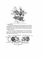
The floating-lever is attached to either left point or right point of the pin so that the
floating-lever may revolve (the left or right point of the pin may be fixed the side of the
governor to which the governor pump is attached). The pin attached to the lower end of the
floating-lever with wax is inserted in the fork.
The floating-lever contacts with the control-rack of the injection pump on the upper
end of the revolving axis through the link which involves the leaf-spring, the link-pin and the
split-pin. The start-spring is attached to the other end of the floating lever. This spring is
operated at the r.p.m. lower than that of the idling. One of the ends of this spring is
-
34-
Start-I.ring Gove..--housing
Oil-_
Governor..ccwer
Fig. 1
connected with the eye of the pin which is inserted in the governor-housing. The pin to
which the guide-lever is attached like a bob holds also the tension-lever likewise. When the
strong governor-spring contacted with the eye of the short rim of tension-lever is strained,
the tension-lever is pushed to the shifter and the governor-spring is streched until the
centrifugal force yielded by the rotation of engine balances with the spring force. In case
when the spring force is stronger than the centrifugal force of the flyweight, the
tension-lever will move until its lower end contacts with the adjustable fu!I-load stopper.
The revolving axis of the swivel-lever is inserted in the governor-bush, and the center of
the lever is slightly eccentric against the spring-eye of the tension-lever.
The other end of the governor-spring is connected with the knuckle which is attached to
the upper end of the boat-shaped swivel-lever. There are two bosses on the side of the
boat-shape which will touch with the side of guide-lever when the engine is stopped so as to
complete their work. The control-lever of the governor is attached to either side (left or
right) of the shaft of the swivel-lever according to the order.
Along with the rotation of the control-lever, the swivel lever will begin to revolve, and
-
35-
Fig. 2
the length of the arm of moment against the revolving axis will change together with the
tension of the governor spring. This is because, as aforesaid, that the revolving center of the
swivel· lever and the spring-eye of the tension lever are eccentric each other. The set-load of
.the governor spring may adjust the adjsuting-screwof the knackel.
The stopper-bolt attached to the back of governor-cover may be adjusted so that it will
contact with the knuckle when the control-lever barely reaches its "STOP" position. In the
governor equipped with a stop-device, this stopper-bolt may be used as a idling-stopper. The
ungleich equipment may be screwed in the tension-lever if necessary.
This is a bush with a pin having the spring load and may be controlled from outside by
taking off the closing-cover of the governor-cover, as it is designed.
The ungleich device will amend the full-load jet volume of the injection pump within a
specified scope according to the set-load of the spring which is adjusted by the constant of
equipped spring, stroke and shim so as to be fit successively for the necessary volume of fuel
for engine between the r.p.m. of idling and that of full-load.
The adjustable screw bush is inserted in about the middle of the governor-cover, and the
idling-sub-spring which is involved in the bush may be adjusted so that it will affect the
control of non-load high-speed rotation as little as possible. However, in case when the
ungleich is unnecessary at the full load jetting volume but the firm control is needed at a
large stroke of control-rock at a lower r.p.m. of idling, a comparatively weak sprIng shall be
involved in the bush of the ungleich-device. This spring, in case when the engine is an idling
-
36-
condition, will push back the shifter from the tension-lever which is contacted with the
idling-sub-spring. Accordingly, the stroke of the control-rack will become larger automatically.
Whether the pin attached to the lower end of the floating-lever with wax will be inserted
in the slot of the supporting-lever on the shaft of the stop-lever or it will be supported so
that it will act at the fork part which is pushed into the. governor cover, will be fixed as to
whether or not the governor has the stop-device. A governor of standard size has no
stop-device. But the device will be necessitated when you want to pull back the control-rack
of the injection pump with a slight power without regarding the position of control-lever of
governor or to use the stopper-bolt as the stopper of the limit of the idling r.p.m.
(2)
PRINCIPLE OF OPERATION
The principle of the governor operation is as follows:
When the r.p.m. of engine increases and its centrifugal foece becomes larger than the
spring force, the flyweight will spread outside. When the r.p.m. decreases the centrifugal
foece will decrease and consequently the controlling power of the governor spring will
become stronger so that if folds itself inside again.
The action of the flyweight is transmitted to the control-rack through the guide-bush,
shifter and link. And the control-rack, when the r.p.m. of engine increases, will be moved in
the stop direction. Then the r.p.m. is limited because the injection pumpsupplies smaller
amount of fuel. When the r.p.m. of engine decreases the process will be reversed. This RSV,
as an all-spread governor, controls the rotations of all kinds covering from the idling r.p.m.
to the maximum r.p.m. outomatically.
If the driver or the operator of the machine will adjust once the control-lever at the
necessary engine r.p.m. by operating pedals or handles, then the governor will adjust the
r.p.m. automatically.
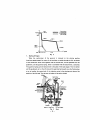
Now let us explain the special operating conditions by taking up severa, cases for
example. Fig. 3 is the performance curve of these operations.
-
37-
Contral-l ever
- - - = position(fuU1
= Contral-Iever
===
n----a'--_o--(
posi tion (idle)
FIG 8 )
icIeIing
( FIG 5) -t-_..Y'\
(FlG9)
Stop (FIG 11 & 121
r.p.m.
Fig. 3
1.
Starting of Engine
When the control-lever of the governor is removed to the starting position
(maximum-speed-stopper) by means of the hand-lever or pedals through the link, the bosses
of the swivel-lever which move together with the control-lever, will be separated from the
guide-lever, and the governor-spring, which is connected with the tension-lever, is stretched.
This governor-spring pulls the tension-lever to the place of full-load stopper. Then the shifter
and the guide-bush act on the left side and the weak start-spring will move the floating lever
so as to transfer the control-rack of the injection pump to the starting point beyond the
position of the full-load. Thus the start of engine will be easily yielded.
Ful-Ioae
Icing
Control-lever
STOP
STOP
Shifter & Guide bush
Fig. 4
-
38-
Full-ioad-stopper
Start
2.
Controlling process at the lowest governing scope of engine.
(Fig. 5)
Once the engine has started, the engine is kept at idling condition by maintaining the
control-lever at idling position (2). In this case the idling position of the control-lever (2) is
slightly before the original position (0).
Under this condition, the governor begins its self-governing automatically. When the
control-lever drawn back from the starting position, the governor-spring is eased so that it
reaches barely the vertical pOSition coming about under the revolving center of the
tension-lever. Accordingly the force of the governor-spring which acts on the shifter,
guide-bush and flyweight through the tension lever becomes very weak, and the flyweight
may spread outside even at a low-speed r.p.m.
Full
Idling
Cantral-lever
FuII-load- stopper
Fig. 5
Idling
The flyweight transfers the guide-bush and the shifter following the direction of the
arrow as shown in Fig. 5. The guide-lever connected with the shifter will move with the
shifter, and revolve the floating-lever, and the lever will pull the control-rack connected with
it to the idling position.
In this case the tension-lever comes in touch with the idling-sub-spring and performes
idling smoothly helped by the spring.
When the r.p.m. is lowered, the centrifugal force will be decreased, the spring will be
-
39-
eased so as to move the shifter and the guide-bush, and the control-rack will be also moved
toward the fu II-load.
In case when the r.p.m. is extremely lowered, the weak start-spring will also begin to act
to pull the control-rack swiftly toward the full-load and the specified r.p.m. may be
maintained.
3.
Controlling process at the highest rotation
(Fig. 6)
In case when the engine at a certain r.p.m. fixed by the control lever is affected by load
or remains non-load, the governor, excepting the case of over-load, will maintain the
adjustment of rotation within the limit which is fixed by the changing rate. Let it be
supposed that a driver moves the control-lever from the idling position to a position where
the proper speed will be obtained through the link by working the pedals (Fig. 6); in this
case. The tension of the governor spring and the moment arm concerning the revolving
center of the tension-lever are increased, the governor-spring pulls back the tension-lever
until it comes in touch with the full-load stopper and the tension-lever pushes the shifter and
guide-bush to the side of the injection pump by pushing them.
FuI-load
Ungleich-Str ok.
Fig. 6
The starting of the Ungleich at the low r.p.m. full-load
-
40-
The guide-lever, the floating-lever and the link will push the control-rack to the full-load
position by transferring the action to the lever_
To transfer the control-rack to the full-load position, it is enough to move the
control-lever slightly from the idling position. Then the ungleich-spring in the tension lever
(if the spring is involved in it) becomes effe..."1:ive. The injection pump supplies much fuel to
the cylinder of engine and the r.p.m. rises. As soon as the centrifugal force exceeds the
tension of the governor-spring, the flyweight will spread itself outside and pulls back the
guide-bush, shifter, floating-lever and the control-rack in the direction of "fuel decrease".
The r_p.m. of the engine will not rise from this point and it is maintained by the governor
under a fixed condition.
When the control-lever is transferred to the position of the highest r.p.m. (Fig. 7), the
governor works as shown in the Fig. 6 as aforesaid_
Fun-load
Starling af Ungleich
JdU
Cantrol -lever
S~P
!t""'~')r::~I--1i,--uuide-lever
Tension-lever
G_ernal'-SDrina,-
Fig_ 7
The highest revolving position of the j:ontrol-lever
In this case, the swivel-lever of course stretches the governor-spring fully. Accordingly
the governor-spring stretches the tension-lever with its large-power to the full-load stopper
and transfers the control-rack to the full-load position. The r_p.m_ of the engine rises and the
control r.p.m. and the centrifugal force also increase.
In this governor in which the ungleich-device is involved, when the tensipn-Iever comes
-
41-
Full·load (the work of ungleich ends)
Control-lever
./ ~ln9l1IlCh'· spr i ng
Fig. 8 Starting of the highest r.p.m. control
Full.load
No-load (idle)
sub.sprikg
Fig. 9. The case as controlled at the non -load condition
-
42-
in touch with the full·load stopper, shifter will directly came in touch the tension·lever along
with the rise of r.p.m. Accordingly, the ungleich·spring will be pressed under a fixed
condition (Fig. 8, Fig. 9).
With the result of such movement as above, the guide·lever and the control· rack move in
the "STOP" direction up to the corresponding volume of ungleich and "ungleich" the jet
volume. When the machine reaches the full·load and the centrifugal force wins over the '
tension of the governor·spring, the tension·lever is pushed back. The shifter, the guide·lever
and the control·rack move in the direction of "STOP" and obtain a new balance at the place
where small jet volume suitable to the load condition of engine may be obtained.
4.
Work of Ungleich
The fuel supplying curve is shown in Fig. 10. In this figure the fuel, which will burn
smokelessly (smoke·limit) at the regular r.p.m. and at a fixed load is ploted by inspecting the
jet condition against engine cylinder per each stroke adopting the r.p.m. as parameter. The
1of
"*~~-=---~-A=-~
..........................
1..-.........~
:!'
.;:
~
Nl
•• p. m. of En9ne
N2
Fig. 10
fuel jetting volume curve in the same figure is shown at the full·load position of the
control·rack by adopting the fuel jet volume which is supplied by the injection pump per
each stroke as function. This fuel demanding curve shall be made similar to the fuel outlet
curve within the limit of possibility. In other words, the fuel necessary for engine shall be
injected smokelessly so as to operate engine without hindrance.
Fig. 10 shows the following facts: The demand for engine fuel decreases as the r.p.m.
rises (worse condition of air inhalation), on the other hand, the injection pump, when
~e
control rack placed on a fixed condition, injects more fuel as the r.p.m. rises. No engine can
burn (consume) this increased fuel without giving out smoke. If the maximum jet volume of
the injection pump is adjusted to themaximum r.p.m. of the engine so as to meet the
requirement at full·load condition the r.p.m. of the engine is lowered and sufficient output
cannot be obtained. In an ordinary case, therefore, the maximum jetting vplume of the
-
43-
injection pump is adjusted as the dotted line shown in the above figure so as to obtain large
torque as much as possible at NI within the low r.p.m. limit.
As aforesaid, without the control given by the ungleich device, if the engine is driven at
high-speed r.p.m. N2 full-load, surplus fuel will be outlet with smoke.
The ungleich-spring and the stroke thereof shall be adjusted so that the jet volume will
meet the fuel consumption at the full-load condition, in other words, the fuel demanding
curve and the outlet curve shall be adjusted so that they may be in conformity with each
other at the time of full-load.
5.
Stoppage of engine
An engine having a governor without a stop-device will be stopped by transferring
control-lever of the governor to "STOP" regardless of the position of the flyweight. Slightly
before the control lever reaches "STOP" or before the knuckle come in touch with the
topper-bolt the boss of the swivel-lever will push the guide-lever and transfer the control-rack
of the injection pump to "STOP" through the guide-lever, the floating-lever and the link
(Fig. 11).
Full-load
Idle
Start
Stapper-bol t
STOP
Fig. 11
In a governor with a stop-device, control-lever may be transferred to "STOP" by moving
the stop-lever to "STOP" regardless of the positions of the flyweight and other lever
mechanisms (Fig. 121.
By means of the two stoppage system the engine will be stopped without jet fuel.
-44-
Cont"" -lever
~~i&..Ii!:ll'--i!l-f~""tin9 -lever
Swivel-leu,er_-..:"!
Stop-lever
4-8 Automatic timer
To the front end of injection pump is attached an automatic timer or a device that
changes the phase of the pump camshaft with its driving shaft according to fluctuation
of the engine speed so as to provide the fittest injection timing. The design is such that
automatically puts ahead the injection timing with a rise of the engine speed and regards
the injection with its drop.
Fig. 3·32 shows the timer in disassembled condition. Each of two flyweights has a
hole by which it is supported on flyweight holder. On it is made a curved surface
designed to help it develop the required efficiency. Bearing pins fixed on the holder
have one of the seats for timer springs.
LEG TIME~ CASE OIL SEAl.S
BEARING
FLYWEIGHT
Fig. 3-32
Automatic timer
-
45-
In appearance the flange looks identical to that of our conventional type hand
timer, but has inside two legs that project in the same phase with flange teeth and keep
contact with the curves surfaces of the flyweights. In these legs are machined the other
seats for timer springs. Each timer spring is held in the said pair of seats, that is, in the
bearing pin by one end and in the leg by the other. These major components are housed
in timer case, which is screwed to the flyweight holder.
Fig. 3·33 A shows the time at a standstill. Being free from centrifugal force, the
flyweights do not lift at all and timer springs are now longest in their setting length.
Fig. 3·33 B illustrates how the timer works at the max. engine speed. Centrifugal
force is now making the flyweights lift. In the picture the letter B indicates flange
leg, whose phase with the pump driving shaft of the engine is designed to remain
constant. So the lift pulls bearing pin A over the distance E, which results in turning the
pump camshaft on the driving shaft so as to put ahead the injection timing.
(A) ATA
STANDSTILL
Fig. 3-33
(B) AT MAX. SPEED
Timer flyweight
The timer for Model 4DQ50 Engine is intended for clockwise revolution and
provides a max. angle of lead of eO as measured on the pump camshaft. At a standstill, it
keeps the injection slowest.
The automatic timer was assembled with 150gr. of grease inside and unless leaked
by chance, needs not be refilled. When the timer disassembled, change grease for new
one.
4-9 Measurement of engine speed
1)
A drop of engine speed below the specified level will disturb the engine
working up to the given efficiency, while a rise above it will cause the
overrunning of the engine itself or of the vehicle it drives. Therefore, both max.
and rated speeds must be always as specified.
2)
As mentioned befQre, pneumatic governor governs engine speed in one-to·one
proportion to the percentage of Venturi opening, hence permits the engine to
-
46-
run at max. speed when Venturi opening is 100"..6. It should be noted that the
governing efficiency depends much upon how the air system is, especially
whether or not it is perfectly air-tight.
3)
Engine speed should be measured under no load in Model 4DQ50 engines
intended for motor vehicles and construction machines, non· load max. speed is
5-10% over the rated speed.
4)
How to measure engine speed.
In case of hourmeter equipment with engine, pick up the hourmeter and equip
a special parts (Fig. 3-34) and measured by tachometer. In this case,
tachometer indicates 1/2 engine r.p.m.
30498-01100
30498-01000
30425-325
\ Camshaft
, Oil,pump dri ve shaft
Fig. 3-34
306Z5 ·zj!Joo
SElf VICE METER
Fig. 3-34'
-
47-
5
COOLING SYSTEM
Thermostat
Thermogauge
IIL::_¢==::~
-~B~yp~a~s~s~h~o~s~e__~~~r---rT~
Engine water
jacket
Radiator
.;::!
\n
--<:-__
I!
---::-,
1----.::c----.".,.,~.-:~~_..: .. - . ..,-;------~!,1
-
Oil
-_-.II
Dral'n cock
'1"'"
cool:7-~Drain cock
(inI: i
~
'-..._.. _...,....-_.. \
j
I
°
)
0'-.0__ ' •• _. __ ~
Fig. 3-35
iUil
;1
j
I
!;U
'1
ii
u
Cooling system diagram
As illustrated in the diagram (Fig. 3-35). cooling water is kept in forced circulation by
centrifugal water pump. The system has a thermostat, whose valve remains close at low
water temperature, letting cooling water circulate between water pump and engine body via
bypass hose, and opens, as water gets hot from absorbing heat from crankcase, cylinder
head, etc., to let it run into radiator to be cooled there by air blasts from fan, and at the
same time, close bypass hose.
Thermostat case on cylinder head has two bosses: one covering hole to fit in thermostat
and the other, water outlet for car heater.
5-1 Cooling water and radiator
1)
For checkup of water level, refer to "Checkup and preparations prior to
starting".
2)
In order to remove scale and dust in radiator and engine water jacket to
improve cooling efficiency, open drain cocks to drain, fill radiator with fresh
oil through its inlet, and run the engine for some 20 minutes for flushing, at
intervals of 500Hr or 12,OOOkm of run, or twice a year (in spring and fall).
If they have gathered much scale and dust, run the engine for about 30 minutes
with caustic soda solution or cleansing liquid in the system and drain it off
-
48-
then fill the system with fresh water and run the engine again for flushing.
Before and after the use of an antifreeze, be sure to flush radiator.
3)
For engine that has rather intricate water piping for the equipment with oil
cooler or for other reason, open bleeding cocks on cooling system, each time
cooling water changed, to make sure that the piping is full in every part. If an
overheat noticed even when thermostat is functioning well, bleed
(~r
eliminate
air out of) the system.
4)
If dust collected on fins, clean them by blowing compressed air or water on
them from fan to recover cooling efficiency. Don't try to remove foreign
matters with a wire or the like. Such a way of cleaning often makes scratches
or cuts in water pipes, hence leading to leakage.
5-2 Thermostat
Poor operation of thermostat will much affect the service life of the engine in the
long run. In case the engine overheats even when cooling system is full and fan working
well the probable cause is that thermostat has got stuck up and remains close. If, on the
contrary, long oreration should not raise water temperature up to the optimum level
(75°-85°Cl. thermostat is suspected to remain open from puncture. In either case,
check it and take necessary measures.
Thermostat is designed to start opening at 76°C and fully open at 90°C under
atmospheric pressure. Continuous operation on cold water will quicken wear of
cylinder liners and rings.
5-3 Tension of fan belt
1)
Every 60H r of run, check the tension of fan belt, Optimum tension is such that
a press with a thumb at
mid-point between generator pulley and water .pump
pulley makes it slack about
12mm. Execessive tension
quickens wear of belt itself
and of water pump and
generator
bearings,
while
lack of tension makes it slip
and a consequential drop of
1. Fan belt 2. Generator pulley
pump 4. Adjusting plate
3. Water
5. Lock bolt
cooling efficiency will cause
Fig.3-36 Checking the tension of fan belt
an overheat. Continuous slipping does it damage, too.
2)
Inspect fan belt at times to see it is not damaged. Keep it always free from oil,
-
49-
grease and dirt.
6
ELECTRIC SYSTEM
RELAY
IIGE~NFAI
'TTiTTT
! ! ! ! ! !
!jJi
t H,
AC 12V-300W
L"-Ir"11i~---!:....!!jn.·
OFF, ON-S
I
: :
j :L-===!ufyf-=vt~
,----
~
I'?..-+-_........_ ... ./
OIL PRESSIJlE
INDICATOR
H
OFF
ON-
S
_
8 G. G. S M
0 0
0
0
0
0 0
0
40mm'
5 rnnI
- - a8smnl
-
STARTER 12V-2KW BATTERY 12V-JOOAH
Fig. 3-37
Diagram of electric wiring (in case of AC dynamo)
IJf£tL:Q&D
_______ 8
G. G, S M
0 0
H
OIL I'RESSURE
INDiCATOR
m:~
0
ON
0
';
')
FUSE BOX
_
Fig. 3-38
40mni
_
5mm1
-
o.esmnl
Diagram of electric wiring ( in case of DC dynamo)
-
50-
0
0 0
[~
.
I H-OFF. ON-S I
~'·i
~,18
~
H
GLOW PILOT LAMP
OFF
ON
S
I
_
G, /G,/ s 1M!
.
00'
0
I
: ,0
0
t
00
0
40mrnz
_Srr:nz
--065"",,'
BATTERY t2V-jOOAH 2Eo
Fig.3-39
Diagram of electric wiring (24 system)
The wiring diagrams given herein cover only the engine. System is of the so-called
negativeearth type and standard specification is 12 volts and wiring diagram shows Fig. 3·37
(in case of A.C. Dynamo) and Fig. 3-38 (in case of D.C. Dynamo). 24 volts (Fig.3-39) is
special specification. In this case, 4DQ50 Engine is equipped with tension pulley in stead of
Dynamo. To follow the service hints given herein in addition to those in "lubrication Table"
will maintain the electric system trouble-free.
Prior to making any service, be sure to turn off battery switch.
6-1 D.C. Generator
This generator is a D.C shung-wound type, whose main components are field coil,
Brush
Ball bearing
armature and brushes.
1)
Check for wrong wiring and
loose terminals.
2)
Inspect brushes at times: re- t.Ii:.......:..::...:...:.::,."",,-IUL...;..;,,,;..:,,;,.;;,...:..;,,;,,~:.:...:J~i'-!ItlZ~-7I
move carbon particles from 1e:illr:7::":'7l~'r-7""':":-:-:~:""':-'7'""1n'-~~llt7:::it~
around them and make sure
that they move smoothly in
their holders. If badly affected
in contact surface or worn
more than 11 mm in height,
replace
setting
with
new
new
brushes~
brushes.
polish
Fig. 3-41
them with #250 sand paper so
-
51-
Wear of commutator
that they make uniform contact with commutator over the whole surface.
3)
Inspect commutator every 500Hr of run. If affected, polish clean with #400
sand paper and wipe with clean cloth wetted with gasoline. Mica pieces must be
0.6-0.8mm below commutator surface. If out, undercut them accordingly.
6-2 A.C. Generator
Fr. bracket
Fig.3-42 Generator Section (A.C. generator)
This A.C. generator is, differently from a conventional D.C. unit, built so that the
armature is installed outside and the field is turned inside as a rotor. It features, among
others, an extremely long service life of the brushes and ability to operate at a very high
r.p.m., because the arrangement dispenses with commutators and subjects the brushes
only to a small current, while its field has very simple make-up as compared with the
armature of a D.C. generator and it is free frpm the need of commutation.
The construction of the A.C. generator is illustrated in Fig.3-42 Revolution of the
field generates a three-phse alternating current in the armature, which is rectified by
silicon diodes installed in the rear bracket and supplied at D terminal. The field circuit is
electrified at F terminal from the battery through field relay and relay, the current
running, on one part, from brush to the field coil through slip ring and on the other, to
E terminal through the other brush and slip ring. Having silicon diodes, the generator
cannot make self·starting as a D.C. unit does by residual magnetism of the field coil, so
is excited to start from the battery.
-
52-
The alternator is designed to limit its own output by itself so that the amature is
free from any overcurrent that may burn it up. It is free from an overcurrent, too,
because the silicon diodes check any current from the battery when
th~
output voltage
of the generator falls below the battery voltage.
To operate the field relay, the alternator has N terminal connected with the neutral
point of the armature. A half of 0 terminal voltage is on this terminal.
Relay
6-2-1.
D.C. Generator Relay .
This unit performs the functions to regulate voltage generated by generator
(constant-voltage regulation) and to prevent reverse current to generiltor.
1)
Make sure that relay terminals A and F are connected with right ones on
generator. Wrong connection will cause relay to burn up.
2)
Connect earth terminal firmly with frame or with terminal E on generator. Its
loose connection will much affect relay performance, causing too much current
to run.
3)
Relay bears a seal placed on after necessary adjustments.
I~s
checkup and
adjustments require precise instruments. If gone wrong, have it serviced at a
specialized service shop, without breaking the seal.
6-2-2.
A.C. Generator Relay
Relay
The relay is a point-action type that regulates the field current by closing and
opening the contact points so as to control the generator output.
6-3 Starter
The starter is a D.C. compound motor of so-called pinion-shift type where
pinion is shifted by magnet switch.
It is provided with an overrunning switch so as to prevent it from driving the starter
any longer than necessary. But remember that, its function consisting only in starting, it
should be switched off as soon as the engine catches.
1)
Keep flange fastened tight. Poor grounding will keep starter from running.
2)
If starting should be difficult, don't run starter repeatedly but Uike appropriate
measures and after pre-heating well, try again.
3)
If a press on button "S" on starting switch has failed to bring pinion in mesh to
set the engine running, switch off starter immediately. If it shquld be kept on
with pinion out of mesh or in imperfect mesh, magnet switch "1ight get burnt.
4)
With long use, commutator will get blackened or spotted with burns and thus
spark harder. So, every 500Hr of run take off brUSh cover and check its
-
53-
surface. If roughened, polish it with sand paper #400 or so and wipe clean with
dry cloth.
Mica pieces in commutator segments should be undercut 0.5-0.8mm below
the sliding surfaces of brushes.
5}
A heavy current runs through starter circuit. Check it and if any loose
connections detected, fasten tight again.
6-4 Battery
Battery requires good maintenance, as it is the Power Source for engine starting and
lamps.
Every 60Hr of run, check and service it as follows. Even when the engine is out of
operation, it should be checked once in two weeks or in summer, once a week, because
it its self-discharge.
1}
Screw off plug and check electrolyte level. Standard level is about 10mm above
pole plate.
If specific gravity has increased from evaporation of electrolyte, and distilled
water.
If electrolyte spilled out of cells (which does not involve an increase of its
specific gravity), add dilute sulphuric acid of 1,280 in specific gravity (at
20°C).
2}
To see how much battery is discharged, measure the specific gravity of its
electrolyte. The following table shows the relation between the degrees of
discharge and hydrometer readings (at 20°C).
Degree of
Discharge
Totally
discharged
3/4
discharged
1/2
discharged
1/4
discharged
Completely
charged
Hydrometer
Reading
1,160
1.190
1.220
1,250
1,280-1.300
Specific gravity varies with temperature. For the correction of hydrometer
reading, apply the formula given blow.
S20 = S + 0.007 (t-20).
S
: Hydrometer reading
S20: Specific gravity at 20°C
t
: Electrolyte temperature (oC)
Long use of battery in insufficient charge will do damage to its pole plates.
resulting in a remarkable drop of its efficiency. Make it a rule to recharge it
before it gets discharged any more than 1/2. In winter, a fall of temperature
-
54-
involves a sharp drop of its capacity. Remember especially that a decrease of
specific gravity in inadequate charge might make electrolyte ready to freeze in
a cold area. (Refer to Sect. 8, "Handling in Cold Weather", Chap. 1).
Good battery maintenance requires moreover such cares as mentioned below.
3)
a) Keep battery always clean and dry.
b) Connect terminals always firmly.
Corroded parts of terminals can be easily cleaned by washing with solution of
sodium bicarbonate. But be careful not to splash it into cells. After polishing
terminals well, connect them firmly and give a thin coating of grease. Never
try to hammer or hit them off or on.
c) Don't put any metal articles such as pliers and spanners on battery. Such
careless doing will short-circuit it with a spark and might cause a serious
accident, to say nothing of early break-down of battery, nor bring naked fire
near it.
7
RE-SCREWING OF MAIN BOLTS
With initial fatigue of gaskets and packings in newly assembled engine and with its long
use, bolts will get loose. To prevent accidents ariSing therefrom, check main bolts at regular
intervals to see if they are working tight enough and if loose, screw again accofdingly. Apart
from this, always give attention to those bolts that can be seen from outside. Re-screwing of
main bolts must be done according to the given below clamping Torque List with fit torque
wrenches, so should be entrusted to your dealer or a service shop.
Clamping Torque List for Model 4DQ50 Engine
Clamping Torque
Bolted Parts
Pitch
12P-1.75
Cylinder head
kgm
ft-Ib
12
86
Main bearing caps
12P-1.75
8.5
60
Connecting rod caps
10P-1.5
5.5
38.5
Flywheel
12F-1.5
8.5
60
Nozzle holders
24P-2.0
5
35
Nozzle tip retaining nuts
22P-1.5
7
50
Delivery valve holders
18P-1.5
3
22
-
55-
Remarks
See Par. 7-1 below.
7-1 Cylinder head clamp bolts
Every 500Hr of run, re-screw head clamp bolts. For this, unfasten rocker case
cover, rocker ass'y and intake manifold, and screw them to specified clamping torques
following the order indicated in Fig. 3-43.
Remember that it must
be placed with apron-shaped
14
parts up. In clamping, screw
o
10
12
o
0
11
0
bolts first a little but un iformly, then tight according
to the illustration.
2
Notes:
1) Numbers show bolt screwing order
2) Camping torque:
Fig. 3-43
12.0 kg.m (861b-ft)
Order to screw bolt on cylinder head
7-2 Main Bearing caps and connecting rod caps
Each time to wash oil pan and strainer, check bolts on main bearing caps and
connecting rod caps, and if loose, screw them tight again.
7-3 Others
Keep the following bolts and nuts tight.
Oil pan clamp bolts
Engine mounting bracket nuts
Engine mounting bolts
Exhaust manifold (outletl nuts
-
56-
Regular checkup and Service Table for Model 4DQ50 Engine
(Consult "Lubrication Table. too.)
Checkup &. Service Intervals
Units & Parts
E
.i2
.,
Description
Remarks
Daily 60Hr 120Hr 250Hr 500Hr lOOOHr
("'\
Air cleaner
(oif bath
type)
Clean pre-cleaner
'-'
Disassemble and clean
element
n
Air cleaner
(filter paper
type)
Clean case and element
,~
0
0
0
Replace element
>-
Of)
0.25mm in cold
engine, both for
inlet and exhaust
valves 0
~
<
Valve clearance check and adjust
0
*
0
Compression pressure measure
E
Oil filter
.,>-
$
Wash inside of case
Oil pan
Fuel filter
At the same time to
change oil or when
bypass alarm lamp
got alight
0
Replace element
*
Of)
5
("'\
'-'
C
Wash inside and strainer
Drain off water and
sediment
0
0
Replace element
Fuel feed
pump
E
$.,
>-
Of)
Injection
nozzles
0
Clean inlet joint strainer
Check injection pressure
and spray
Remove carbon from
nozzle seat packings
a;
...
:>
Check fuel level and
refill
Fuel tank
*
C
*
0
Drain off water and
sediment
0
0
0
Check water level
.
E
Radiator
>-
...
.S
Change water Wash
inside
0
Of)
Clean cooling fins
0
Check tension and adjust
0
"5
0
Co>
Fan belt
120 ±Skg/cm' 0
0
Wash inside
$
0
-
57-
Before and after
the use of antifreeze
Checkup & Service Int!lnlals
Units & Parts
D.C.
Generator
A.C.
Generator
E
'"
>.
..
Daily
Check brushes: replace
if necessary
0
Service comm utator
0
Check brushes and
slipring ; replace
if necessary
0
0
C
to
Starter
Dismount to check
pin ion clutch
;;;
;:u
0
Check electrolyte level
and refill
0
Measure specific gravity
of electrolyte
0
Screw again
*
Usually once in
two weeks. but
once a week in
summer
Battery
Main bolts
Notes:
Remarks
60Hr 120Hr 250Hr 500Hr OOOH
Check brushes and
commutator
~
'".~
Description
o
o
General
In very dusty areas
*
First servicing for new engine or after overhauling
o
Services to be made by your dealer or a service shop
-
58-
0
See "Clamping
Torq ue List'· 0
CHAPTER 4 TROUBLE-SHOOTING
When the engine has got out of order or something wrong happened with it, consult the
following instructions to take appropriate measures.
In the event of any serious trouble such as arisen in the inside of the engine or with fuel
injection pump, ask your dealer or a service shop for necessary repairs. Whenever any trouble
noticed, put on record its detailed descriptions and the odometer reading on that day.
In disassembling to research into the cause of trouble and repairs, take necessary
measures to keep off dust and arrange removed parts so as not to miss any of them, as well
as to permit easy reassembling.
-
59-
1. TROUBLE SHOOTING CHART
EDsiDe
lacks Abaormal expower
baust smolce
EDgiDe will not start
Complaint
EDgiDedoes
not tum
EnJiDe turns
cmr but does
not start.
.,;
..
::
..."' --...
Ow
~
0
0'"
-oJ!
Probable cause
;;
0
-0
~
"-0
,,~
J! ..
oJ! ::c:c
"0
~=
Zoo
tl;0~ •fuel supply
JA.l"CUOIl
i.
When
0
operatiDg
..... J:i. ~
.
Ci
..
,;..
Ii
.i: . . = '"
~
~e . . " ~=
",,,, a. a. ;. ~ ~
i J:e1.. oil
! !
...lie'" ;e
. J:
J:1.5
ell"&b
'
"
~ ~ . " ~
~ .. ".
~ .. ..
..
....
.5~;
el;!
ell
"
"
e.:
!..=
~l;!
li
i
"' .... ... .. =
-=..= '=1
i-= "&be
J:.'"
°e -e
:c :!! < ~Ii
~~
<.
Ofti'
~o
CO
0
:!~:!
cn~"
g
..
-0
~
!
0
~
0
!!
OIl
.c
"-0
!!
III
.. 0
00 00
",,,
",-
1111:1
Engine
hunts
~§
I!
~
~E
III.
0
0
1--,-
.i:
~
.:::
..."
-="
li
..e
0
·0iI
e
III
,;..
]
OIl
,;.. ::"
.l:I
-a
'"
l!!
eOIl
~
~:!
;0
'e" '" ..c'"
III III
'" ~
. .
.c
.:I
u
;
Oil '00
;
~
0
0
pump
Greater wriance of injec tion quantity
0
0
0
0
0
0
0
0
0
0
0
0
0
0
Defective fuel injection
pump seals
lDsufficic:Dt injection
quantity
0
0
0
0
Excessive iJljection
quantity
e
!
;; ~ction
!OU1ced
timias
coo
0
'""
timias
coo
0
"
Injection
retarded
0
0
0
0
Excessive fuel return from
injection nozzles
~
0
0
Improper fuel spray !rom
injection nozzles
0
0
0
0
Defective autOmatic timer
0
0
0
0
0
0
0
De£ec:tiw: gowmot control
spring
0
l\IaIadjusted goWlrDOr
damper sprins
0
Engine speed coo low
Failure of engine
properly
CO
Stop
Fuel oil viscosity too bigb
0
0
Poor grade of fuel oil
0
0
0
0
0
0
o.
0
0
Poor grade o£ oil
Oil 'Viscoaity too high
e
0
..
1i:
'"
l'
j
"
...l
Oil viscosity
COO
0
0
low
low oil pressure
Excessive oil Jeak
0
Pumping up of oil
Clogged oil fi1ter
Defective oil bypass
alarm or lamp
Defective oil indicator
switch or lamp
-
60-
0
,
,
,
,
,
,
,
,
,
I
I
0
....
0
."
I
,
,
,
,
,
~
r;
Po
::
,,,,,,,,
,,
,
,,,,, ,
,,,, ,,
,,, ,,,,
,,,,, ,,
, ,,
,
,,,,,,,
,, ,,
,,,,, ,,
,
,,,,
,,
,,,,, ,,
, ,
I , , ,
,,,,,,,
,,, ,
I
I
I
I
I
I
I
I
I
I
I
I
I
0
I
I
0
I
I
0
I
I
I
I
0
0
I
I
I
I
I
I
I
I
I
I
I
if go. fir c:
f".'Wr • ji
!a ~a 1
C
Ie
r;
I!.
~ II
It
"n
"
::;;
l
!!:
It
," 1 1
~ g~'~' 1.
1 ~'~' F
It
~
0
0
I
I
I
I
I
I
I
I
0
I
I
"
I
,
,
,
,
f
[
r
n
~
0
It
1If. !!:!!:
i
.e.
::;;
-----
I
0
I
I
I
0
0
I
I
I
I
I
0
I
0
0
I
I
I
I
I
I
0
0
0
,, , , ,, ,
,, ,,
,, , ,
,,
I
:E
]
I
I
E::;;
It
I
I
I I a
1 1l
It
I
, ,
, ,
,
, , ,
,, ,, , ,, , , , , ,
, , , , , , , , ,
,, ,
I
I
,
I
, ,
0
,
I
I
I
I
I
I
, ,, ,
, , ,
, ,, ,
,
,
I
I
•
I
r~fi ~fi
Ii'"
IS:
al
I
0
0
,
I
I
0
...s
0
0
0
0
I
I
I
I
I
I
I
0
0
0
0
0
0
0
I
I
0
I
0
I
I
I
I
I
I
I
I
0
0
I
if
s,§'
Ge-
IiPg: 11111 ,
It
0
0
I
"'Ie
,Ft
J
!'
,
,
,
,
,
, , , , , , ,
,
, , , ,
, , , ,
, ,
, , , , , , ,
,, , ,
, , , , , ,
, , , , , , ,
,
, , ,
,,
, , , ,
,, ,
,, , , , , , ,
,, , , , , , ,
I
J.i
gg
[~
,
,
,
,
,
,
,
,
I
I
0
0
I
Bnglne vibrates excessively.
0
0
,
,
,
,,
Bngine staUs.
0
Bngine does not pick up apeed.
,
,
,
,
,
I
0
,
, ,
I
,
I
I
I
, , ,
I
,
,
,
,
I
I
I
I
, ,
, ,
, ,
, ,
Bxcesslve fuel consumption
Bxcesolve oU consumption
OU Is dUuted by fuel.
Water In oU
Blow-by
When enr.ne stopS,
warnins amp does not
come on
Wornlng lamg comes on
at low - spee operation.
Warning lamp comes on
at high - speed operation.
Water temperature too
high (Bnglne overheats)
Water temperature too
low
Indicator lamp does not
come on when engine
stops.
IndIcator lamp comes
on at hIgh - speed
operation.
r
~
II
h'
f
Bngine operates at hlSh speeds
but faUs to stop.
Bnglne turna over In reverse
direction.
,
• • I • • • f • •
~
l..
g
.:l
~
Poor response for deceleration.
...
:E
::;;
"
j
...
.
It
'"
jg'/!
~
B'
I~
l~ii
I
'i
~
Iff. I
t
..
3
~
, Po
I
0;
;
g'
...,i
if
i
g
Ii'
Enslne proper
W~
Electrical system
a' W1iI'!I IS 8'6' iW "'1.E"'
e. 9~ eJ 11~i n.'
~~
;;1 Ii
~ ;.~ 1
<1
[a"
if§
<1
1 !ti~:I~
ti ....
i
i ~·II·
9
,
'"
I ' '"
I
,
"0
-,
,, ,
,, ,
0, ,
8 9
ig
,
,
..
..,
,
,
2
"
2( Ii
Ii)_II!~.
II J~ sft 1
J.t-<g
r..
..,
'" Ii2 5~
Ii i 1
Ii ( t
,
"
,
"
,
"
"
0"
,
'0
0'
,,
,, ,,
, 0
,,
o
'"
'"
'"
,0
, 0 ,
'"
, , 0
'0
, ,
0
,0
, 0
,
'"
0
0
o
o
, 0
,
,
I
o
I,
0'
0
0 0
,
"
"
"'"
00
,,
00
00
,,
,,
g 51~
f.
A UtUo oxhaust
smoko
..
go
~ ..
.
' 0 0 Too
ex!i It
haustmuch
smoke
it
Stutlnll motor does nol
turn over sufficlontly to
Clank enslne.
..
Enslne can be
cranked manually 0 ~
,,
, ,
0 0
"I
0
,
I
, , , I Heator plugs do not glow red.
"
'"
,
,,
I
,,,
"
0
o
"
I I
I"
I
,
, ,
, ,
'"
,
0"
0'
I,
"
, ,
"I
I
0'
I,
"
, ,
'"
,
0
I,
"
, ,
'I'
I
'0 0'
I,
"
, ,
'"
,
0'
00
I'
"
, ,
'"
,
'"
0
I,
, I
'"
"
,,
,,
,,
,,
'"
'"
,
,
,
o
Enslne cannot bo
cranked manuaUy.
~"
o
"
'I
ai Itit J
, , , I Heator plugs glow red too ouly.
0
"
]1'
I
0
o
," ,
,,
, 0,
0
11'>-
WhenldUng
Whlto oxhaust
, 0' Ismoke
o 0 0 I Black exhaust
smoko
0
0
r
A Uttlo oxhaust smoke
0
00
,,
!
I
l'
00
o
f
iIi!
,, ,,
0
,
,
Nooxhaust
smoke
,,
,
'"
I'
(
,,
,,
'0
, ,
'I
j
,,,
,,,
,,,
,,
"
'"
I
i
'"
0
I
1~
'"
"""
I,
, 0 0
S'
~
"""
0
, 00
If.. . 1;.
n"
,
, , 0
, 00
iii
BJ'
, " , " , " "
,
00
"
AIr system
lill
I Iit I lillff
11.r."
81
s· 1(2.t!~ 2
~!~!,,~-~~ i~ I fj''OJ,§'' ~ 1.11
fj s"ll"i' ~lt
a;' ..
1
, , " "
,,,
o
1
J:
1'11
Ii
~ P
Ii!
,, ,
,, ,
~
iI.l1irl.
th Jj
CooHna system
.i i t1 t1'2.g! 29 r!l t15't1 t1 i t1 t1
"9
aiii ! ~~;
1 ~ <1 <1 B· roB· ].i" [<1 <1 S ~
If
, 0' I Enslne knocks excessIvely.
Ii!
, , , I Enslne I, noisy.
I
0'
, 0'
I Enslno runs Irregularly.
I When IdHna
, 0' I When operatlna
JI
(. For detailed information refer to the separate table.)
0::
.2
i8
" §.v
§.
...
.=
v
""
] .;..
.s co0::
S
r::
III
0
0
0
~
02
:E!
OJ
~
e
.s
80. ~0
-.2
e ..
.
:.§
U s
...::0 0.:1
. ! ..
';;
i."r:: "r::r::
III
....
.
1
..... t=
b
"S
..;
"r::
r::
III
~;:!
J"-loS
.:0 .:
0
i. i.
e e
ill
r::
=~
8 r: ..:
7l
..:
~
8
'0
18
III ...
III
r::.l:I
0
>.
...
.&>
.! "
:I
... g
0::-
Abnormal
Defects in lubri- water
terneating system
perature
~
" III" 6
...
..e~-
0::': 0::=
0.2 o~
03
Defective
cbarging
generator
. :sl
0 ....
rlf - v eo
e8- 0'= "
"
8'"
00
80 8 0 !i!
"'iiI:
I! 0 ~
e ..
:~=
e:!
r:: .; S'
8r::e o
'S >. "Q.!I
.as!... 0'"
.,,S .. .=
"
~
or::
0.!P
.&>
r:: .. e
.s
:!f'
-iii: oe" -.=
=>..2 ~8.5
~~8 r::~ -a-&.
!i iii: .1;~.=
.....
:;- :;:E!
cOr:: _0
c==..0
;t:iil:g lI'Oj ;t:Oj ~, ~s _r::v
~
...
.n"
~1
i-:'
......
I-i
t-i
.
-:es
il
0
0
0
-..r!-.:
0
•
•(Adjust full-load settiDg of gowrnor.)
0
0
.•
0
0
0
0
0
0
0
0
•
0
~etighten and replace gasket
if necessary.
0
Replace crankcase.
Check f:>r connections and repair. If
necessary replace part (s).
Repair and replace if necessary.
0
0
0
0
0
0
0
0
0
0
0
0
0
0
0
0
0
0
0
0
0
0
0
0
~eplace oop~r pac\cing (s) and
if necessary eater plugs.
If necessary replace cbarging generator
Adjust and replace if necessary.
Connect wires properly.
•Repair and replace if necessary.
Repair and replace if necessary.
Check and replace bearing (5) with
undersize one (s) if necessary;
Retighten.
Re-time !iming gear train or
adjust valve siillCage properly.
0
0
Repair and replace if necessary.
Repair and replace starting
motor if necessary.
Repair or ~lace niDg gear.
Replace pwon.
Reclwge or replace battery.
If necessary heat it.
Replace part (s).
0
0
0
0
m
Heat. oil
from ~ottom side at
starting.
ter 5tartmg, warm up
engine sufficiently .
,
0
0
Possible remedy
~~ ... 1
Replace part (5).
Adjust valve clearance to 0.3 mm.
Repair.
0
0
Replace geat (5) or idler bushing (s).
-
63-
2. TROUBLE SHOOTING CHART (APPENDIX)
Probable
Improper fuel supply to fuel
injection pump
PossIble remedy
ClUte
Closed fuel tank supply coclc
NO" fuel in tank
Coged fuel lines
Ajr in fuel system
Coged fuel feed pump inlet
Open the coclc.
Fill fuel tank.
Repair or clean fuel pipes with air.
Retighten attaching parts or replace
fuel pipes.
Remove and clean stamer.
strainer
Greater variance of injection
quantity
Defective fuel feed pump
Leak in fuel lines or connections
Cogged fuel filter
Ajr in fuel system
Repair.
Retighten connections.
Disassemble and clean filter.
Bleed air out of fuel system
Jammed plungers
Jammed tappets
Worn plungers
Worn tappet cams
Worn bearinp
Worn or broken plunger sprinp
Loose pllmger pinions
Replace plungers.
Replace tappets.
ReplaCe plungers.
Replace tappet cams.
Replace bearinp.
Replace plunger springs.
Reinstall properly by matching
stamped marks.
Replace valves.
Replace valve spring.
Defective delivery valves
Worn or broken delivery valve
springs
Insufficient injection quantity
Governor stop lever link is
binding.
Control rack is sticky.
Jammed plungers
Jammed tappets
Worn plungers
Worn tappet cams
Worn bearings
Loose plunger pinions
Improper full-load setting of
governor
-
64-
Repair link properly, placing
lever in neutral position.
Relubricate or repair.
Replace plungers.
Replace tappets.
Replace plungers.
Replace tappet cams.
Replace bearinp.
Reinstall properly by matching
stamped marks.
Adjust governor setting on
bench.
Probable cause
Excessive injection quantity
Improper fuel spray from
injection nozzles
Possible remedy
Stop lever jammed in "increase"
position.
Improper full -load setting of
governor
Loose plunger pinions
Repair lever link properly, placing
lever in neutral position.
Adjust governor setting on bench.
Sticking needle valve (s) in one
or more nozzles
Damaged nozzle tip seats
Worn or broken nozzle springs
Extremely low injection pressure
Repair and replace nozzles if
necessary.
Repair and replace seats if necessary.
Replace nozzle springs.
Adjust Pressure to 120 ± Skg/cm 2
(l706.4±71.l Ib/in2 ) on nozzle
tester by inserting shim (s).
Remove carbon.
Carbon deposited on packings
at nozzle tips
Reinstall properly by matching
stamped marks.
Injection timing too advanced
Improper installation of fuel
Injection pump
Incorrect installation of timing
gears
Re - time properly by tilting injection
pump toward engine.
Re - time timing gear train.
Injection timing to retarded
Improper installation of fuel
injection pump
Incorrect meshing of timing
gears
Worn cams, tappets or bearings
of fuel injection pump
Re - time properly by tilting injection
pump outward.
Re - time timing gear train.
Poor grade of fuel oil
Water in fuel
Use good quality fuel.
Use good quality fuel.
Lack of oil in oil pan
Add oil to prescribed level.
Replace damaged pipes or packings.
Retighten loose parts.
Poor grade of fuel oil
Low oil pressure
Air in oil strainer
-
65-
Replace.
Probable cause
Possible remedy
Low oil pressure
-cont.
Defective oil pump
Clogged fuel lines
Defective oil pressure valve
Clogged oil filter
Leak in lubricating system
Repm.
Flush.
Repajr and replace if necessary
Change element and oil.
Repair.
Pumping up of oil
Excessive oil in oil pan
Worn cylinders, pistons or
piston rings
Sticking piston rings
Drain oil to lower oil level.
Repm and replace parts if necessary
Repair and replace damaged rings
if necessary.
Replace valve guides.
Overhaul engine if oil -laden gases
are exhausted.
Worn valve guides
Prolonged operation under no
load
Insufficient m
Poor compression
Clogged air cleaner
(paper element type)
Clogged air cleaner
(Oil bath type)
Clogged intake manifold
Defective valve seats
Sticking valve stems
Failure of rocker arms to
lift valves
Worn cylinder, pistons or
piston rings
Sticking piston rings
Exhaust gas leak in cylinder
head gasket
Worn or broken valve springs
Jnsufficient torque of starting
motor
(at starting)
-
66-
Clean and replace element if
necessary.
Wash interior.
Check and clean.
Repajr
Repm and replace valve stems
if necessary
Adjust valve clearance to 0.3 mm
(0.OI2mm).
Repair and replace parts if necessary.
Replace damaged rings.
Retighten and replace gasket if
necessary.
Replace parts.
Probable cause
Insufficient coolant
Failure of radiator to
dissipate heat properly
Possible remedy
Insufficient coolant
Overheating
Water leak in unit seal of water
pump
'Crack in crankcase water jacket
Water leak in other parts
Air in cooling system
Rust and scale deposited in
radiator
Dust and dirt around radiator
Slippage of fan belt
Inoperative thermostat
(kept closed)
Radiator dissipates heat
excessively
Jammed moving parts
Extremely low atmospheric
temperature
Uncovered radiator
Inoperative thermostat
(kept open)
Sticking cylinders, pistons
or piston rings
Sticking main bearings and
crankpin bearings
Sticking cam bushing and
idler bushing
-
67-
Add water to prescribed level.
Replace part (s)
Replace crankcase.
Check, and repaU.
Bleed aU by loosening aU bleed
plug, drain plug, or hose clamp.
Flush.
Flush.
Adjust' belt tension.
Replace.
Cover radiator.
Replace part (s).
RepaU and replace part (s) if
necessary.
RepaU and replace part (s) if '
necessarr·
-68-
CHAPTER 5 OVERHAULING INSTRUCTIONS
1.
GENERAL INSTRUCTIONS
1)
At present we cannot say when your Model 40050 Engine should be put to a
thorough overhauling, for it presupposes under what conditions the engine will be
sued, but can mention as general hints the following cases where an overhauling is
required.
a) When, engine parts having been uniformly fatigued (or worn) down from long
use, involving a drop of output, it is judged better to overhaul it.
b) When an increase of blow-by out of crankcase has caused a notable drop of
engine output.
c) When oil consumption has increased.
d) When, with nothing wrong with oil system, a remarkable drop of oil pressure is
noticed, which is judged ascribable to the wear of metals, etc.
e) When water leaks into oil.
f) When such a serious trouble has happened inside the engine that cannot be
remedied by usual services or permits the replacement of broken or affected
assemblies.
2)
In taking apart the main parts such as pistons, connecting rod, valves and metals,
arrange then or put numbers on them in an appropriate way to place them later
where they were. Remember particularly that caps on connecting rod and main
bearings, being machined in pairs with respective bodies, cannot be replaced
separately.
3)
When the engine overhauled, make every service specified in "Retular Checkup
and Service Table".
4)
After a thorough overhauling, practice an adequate running-in and performance
test on bench, coupling it with a dynamometer, so as to adjust it perfectly for
actual operation, for example, on the vehicle.
For fuel injection pump and governor, they must also be tested, when
overhauled, individually on a fuel injection pump tester in order to make necessary
adjustments. New units supplied in an integral assembly, "injection pump general
ass'y", can be readily put in service, as already adjust thoroughly. For informations
about the engine bench test and individual adjustment of injection pump and
governor, ask your dealer or service shop.
5)
Reference to "Parts Catalogue" will greatly help you in knocking down and
- 69-
reassembling the engine. Remember that special tools are available for those
operations. (Refer to Chap. 6, "Tools")
2
CYLINDER HEAD AND VALVES
2·1 Retace of valve seats
Valve seat angle is 45°. After a
rough machining with a 45-degree cut·
ter, give perfect fitting. Standard seat
width is 1.4mm. Excess in width affects
airtightness. If valve seat has become
wider, cut the face accordingly with a
cutter with an end angle of 120°. Use a
c:
seatT==~~~~~~~~=~'~
cutter of 42tP in outer diam. for inlet angle
valve seats and of 3:U for exhaust ones.
I
! Sopt
Valve depression
facing
:E
Valve depression must be within a range
Fig. 5-1 Valve seat
of 0.8±0.2mm. In case valve has sunk more than 1mm, which requires a valve seat insert
be fitted in, ask your dealer or a service shop for the service. If valve face scratched or
worn, replace with a new seat so far as available. It can, however, be ground until margin
becomes 1.2mm. .
2·2 How to replace valve guides
To remove valve guide, press it down with remover, while to fit in a new guide, use
installer so as to set it with the top end 18mm above the surface of cylinder head. (See
Fig. 5-2)
2-3 Combustion chamber jet and director
To remove combustion chamber jet, lightly press it out with a long bolt of 10tP, as
illustrated on the right.
For new jet, tap them in uniformly until their surfaces get level with that of
cylinder head. Setting directions are indicated in Fig. 5-4. Having set them right, calk
each at a spot with a punch. To replace directors, hammer new ones so as to place jets
midway between inlet and exhaust valves as indicated arrows.
-
70-
Remover
Installer
Fig. 5-2 Replacement of valve guide
Fig. 5-3 Pressing out combustion chamber
2-4 Rocker shaft brackets
To remove rocker shaft bracket, prior to loosing center bolt 1 , loose short ones
2 , lest bracket should be strained to break.
In bolting it down, screw those bolts in reverse order, that is, first long bolt 1 and
then short ones 2.
In setting brackets, allot enough clearances to permit both left and right rockers to
move smoothly.
Fig. 5-4 Setting direction of combustion
chamber jet and director
3
Fig. 5-5 Bolts on rocker shaft bracket
PISTONS AND CONNECTING RODS
3·' How to remove and install piston and connecting rod assy.
In Model 4DQ50 Engine, connecting rod large end has a larger diameter than
-
71-
with connecting rod, cannot be pulled out
upward (that is, toward cylinder head),
but through the bottom of cylinder
with crank shaft off.
To install piston coupled with con·
necting rod, press it into cylinder from
below, then install crank shaft. To
install piston, use the special tools. But
don't forget to coat it with oil in
advance.
Fig. 5-6 To install piston
3-2 How to couple piston with connecting rod
Pistons and connecting rods are marked with serial numbers, No.1, No.2, No.3
and No.4, according to their arrangement as seen from timing tear case.
How to couple together each pair and to set in cylinder crank-case is illustrated on
the right.
3·3 How to remove and install piston pins
Fitting of piston pin is such that does not permit it to be pressed in by hand at
normal temperature. So, warm up piston in boiling water to expand the inner diam, of
piston pin hole, then remove it or install by hand. Never hammer it in cold piston.
Arrangement of piston rings on piston is an shwon in Fig. 5-8.
Combustion
chamber side
I
7
1. Compression ring
Fig. 5-7 How to couple piston
and connecting rod
2. Oil ring
Fig. 5-8 Arrangement of piston rings
72 -
Top and oil rings are chromiur:n.plated in sliding surfaces, while the other, namely,
2nd. are tapered, install these taper rings with marks "UP" on cut ends up.
To oil ring is attached a spring type expander to provide high and uniform contact
pressure. The ends of spring are butted to each other with a short steel wire between
them.
Arrangement of piston ring cut ends is indicated in Fig. 5·9.
b"
Direction of CAM SHAFT
e<"
.~~
.
'
J,.~
"oS-
(Direction of piston pin)
--,,
,"
~'O")'" "-
III
_.._"--~
'~
"J-
"~~
Direction of
~ c.
_~."
COMBUSTION CHAMBER JET v<" $.
..,,<""
"04-
Fig. 5-9 Arrangement of piston ring cut ends
4
CYLINDERS
4-1 Oversize
In Model 40050 Engine, cylinders, being cast in one body with crankcase, have dry
liners.
When they have got worn more than O.2mm in bore or cut deeply in lines, machine
them to a suitable oversize. Oversize pistons and piston rings are available in three sizes:
+0.25, +0.50 and +0.15.
4-2 Cylinder liners
If oversize parts are not available or when they have got worn over the limit of use
(+1.20mm), change cylinder sleeve. For detaiis, ask your dealer or a service shop.
5
BEARING METALS
5-1 General cautions
Handle metals on main bearings and connecting rods always with good care not to
scratch or otherwise damage their bearing surfaces. In assembling them, clean bearing
surfaces and coat them with oil; then clamp them down, making sure that they are free
from any strain.
-
73-
5-2 How to assemble main bearing metals
Of each pair of main bearing metals, assemble that which has a groove in the middle
that -is, on crankcase up side, especially the other with thrust bearing on the side of
timing gear case. To prevent leak of oil, give a thin coating of liquid packing to their
contact surfaces with main bearing cap cases on both ends. For connecting rod bearings,
either of the pair can be assembled upon the other.
5-3 Undersizes
To both main bearings and connecting rod bearings, metals must be renewed when
their clearances exceeded O.2mm. When replacement of metals not considered to
produce satisfactory results because of crank shaft being unevenly worn or streaked
deep, grind it so much as to fit to any of undersize metals which are available in three
sizes; -0.25, -0.50 and -0.75.
6
TIMING GEAR
6-1 Timing gear train
___::::::=::::::::
,~~~~~\\
!
I
__ 4"' "-?~
LI:'
L
-i=
ffi-- -"~,\-Y "~"--.-7"
: ;/
f
"-
'- ~
-
'/'"
/1
/" i
,
-
:
"~
1
i
I
I
/
,/
/.'
~
I:
i /'}
.~/
/,/""
I
I dl er
Autotimer jet
(WI 43 teeth) (not provided but
for autotimer)
Fig.5-10
Timing gear train
-
74-
The view of timing gear train with cover off is shown as (Fig. 5-10). To install gears
that were taken apart, bring #1 cylinder piston to top dead center and holding it there,
mesh gears one after another with idler, following their numerical meshing marks, as
illustrated in Fig. 5·10.
Align autotimer key way with mark line on injection pump gear.
6·2 Valve timing
To install gears according as indicated with numerical meshing marks dispenses with
the trouble of checking valve timing. For reference sake, however, valve timing diagram
is given in Fig. 5-11. Every cam having a symmetrical profile, checkup of valve tim ing
requires to measure crank angle, at max. cam lift to see if it equal to the angle indicated
with broken line in Fig. 5·11. The procedure is detailed as follows.
Take for instance, No.1 cylinder inlet and exhaust valves. First set valve clearances
by means of plane plates with uniform thickness. of 3-4mm, and put the thinnest
INLET VALVE
CLOSES.
Exhaust
EXHAUST
....... VALVE OPENS.
~,
c~m-~-~
.
max. tift
'>11".
1'· .
A
4"~~O
j,
J
..
:5
j. .
'·Inlet cam
max. lift
-:
..
::>,...
..
.! .....
•
C
~
~
Q.~ ...
~! ,c
:; e
.. II
Q.
~~!
...
~
~.2
-
Crank Angle
Fig. 5-11
-
Valve timing
75-
(O.05mm) of thickness gauge blades between valve tops and rockers. Now turn crank
shaft slowly until gauge blades are pressed tight, this point crank angle is valve lifts reaCh
point A and B shown as Fig. 5-11. The mid·point between them corresponds to max.
cam lift. Compare the results of measurement with the specified crank angles.
7
OIL SEALS
Oil seals on front and rear ends of crank shaft must be centered right. So take care in
clamping down timing gear case and rear end oil seal.
The part to install front end oil seal has concentricallY'machined periphery. Center the
seal so as to fit to it. Meanwhile, for rear end oil seal, center it on basis of its periphery. In
either case, a special centering tool is available.
Remember that rear end oil seal must be set with oil leak·off knotch in slinger down.
Prior to installing oil seals, coat their lips with pure engine oil.
8
MOUNTINGS
On motor vehicle, rubber cushions on front mountings form a paralle-Iogram in free
condition as shown in Fig. 5-12, and a rectangle under load. Remember this in setting them.
On construction machine, three point support mounting is used. Timing gear side has
cushion rubber.
./1
\
f--+'\
~
~I.~ ,
•
.$-
Fig. 5-12
Mounting on motor vehicle (in free condition)
-
76-
9
OIL PAN INSTALLING
Oil pan of Model 40Q50 Engine is designed so as to be installed with its center in
alignment with those of crankcase and crank shaft. At either end, fasten it tight enough not
to leak.
Main bearing caps on both front and rear ends have grooves. Fit retainers in those
grooves as illustrated in Fig. 5-13. Then, to their corners, put the ends of side packings (cork
plates). and fit semi-circular rubber-packings in the grooves. To apply liquid packing to
corner intersections will prove very effective in preventing leakage.
Coat semi-circular rubber packings with oil on the surface so that oil pan edges will slide
easily on. Finally screw bolts (4 pieces each in front and rear) uniformly in order not to
strain packings.
Fig. 5-13
10 OIL PUMP
Arrangement of oil pan
packings
In fastening down pump case cover, align its setting mark with that on pump body.
Pump case
Impeller
Bearing
Water pump
77 -
11 WATER PUMP
If any play developed on water pump shaft or water leaking, disassemble pump in the
following procedure and service as required.
First, remove fan coupling flange with puller and take off snap ring. Then open rear
cover and take out inner components. Impeller can be pulled cut with puller.
Check unit seals and if badly worn or affected in floating seat surface or carbon worn
off, renew them.
Of new bearings, grease may come out a little, but this means nothing particularly
wrong.
12 BOLT SCREWING
For screwing of main bolts, the necessary instructions were already given in
1)
Sect. 7, "Re-screwing of Main Bolts", Chap. 3. The other bolts should be screwed
with reference to the following table.
Nominal Thread
mm
6
8
10
10
12
Pitch
mm
1
1.25
1.25
1.5
1.25
Plated
Kgm
(ft-Ib)
0.9
(6.5)
2.1
(15)
4.3
(31)
4.0
(29)
7.4
Not plated
kgm
(ft-Ib)
0.7
(5.0)
1.4
(10)
3.0
2.8
(20)
5.2
(38)
Clamping
2)
(22)
Prior to screwing the following bolts, coat their threads with oil-proof liquid
packing ("atmosit'1 for prevention of leakage.
3)
(54)
4
lower clamp bolts on crank shaft rear end oil seal
3
lower clamp bolts on timing gear case
2
clamp bolts on flange plate to couple injection pump
2
fixing bolts on breather
Packil195 (gaskets) and liquid packings to be used are listed below.
-
78-
Materials of Packings
(Gaskets)
Liquin Packings
Cylinder head
Copper asbestos
"Three Bonds" No. 201
Front plates
Rubber asbestos
Uses
Timing gear case
Timing cover
"
No.2
"
"
No.2
"
"
No.2
"
No.2
Oil pan (sides)
Rubber cork
Oil pan (ends)
Rubber
"Atomosit"
Oil filters
Rubber asbestos
"Three Bonds" No.2
-
79-
Model
SeaiaT Units ! Parts
1.AiI:
1
I2
3
Checkup Items
4DQ 50 Eng
ominal Sett ing
Staniard
n e
Limi t of Repair'
(Clearance)
Not below rated
speed 1~
nOr above it
70D-750r pm(Pneuma tic Not above SOO
Govl~
r.p.m.
650-700q:m(Weehand.;,~
15-10qb higher than
rated speed
Max. speed
Min speed
I
I
Engine preformance (on bench)
4 CoEnpression pressure
5 Engine oi 1 pressure
!
Above 20q/cm 2
'(at 15D-200r.p.m. )
~-4.IqVcm '\.at 1,oUO
r'r~~cm Z~~hi~er
1.5
in ldl ino
General
Not below
16kg/cm 2
Not oep:/W
2:~cm2z
O.
em
I
...
..c:
CD
...
6
e
Valve timing
-0
~
±3
(crank angle)
...""...
-'"
::I
;:;
7 Injection
n
~
"-»
1
...
II>
-0
II>
'"
Cyl inder
bore
""
.: ~
-"-» ""...
.:
o
Top
<.>
8
star~ing
tlmUlg
84"tP
Bore
out of round
Taper
--
Strain
surface 9
,
Projection of pistons
10 abO'ie cyl inder crankcase top surface
Per iphery 111
Outer diam.
!!
...
""0-tIC
c
~
S
c
~
...-
'"0c
'"
P-
Rings and
ring
groO'les
12
Piston pin
bosses and 13
piston pins
Weight
,
~e~igh
Width and
standard
clearance
llUIer and outer diams
and standa1d
e earans
Wei~difference
14
Top
2nC1
oil
4 PiStonS
.g
- 80-
±10(erank
angle)
+0.035-0
+0.20
~ess than 0.015
ess than 0.015
Less than 0.05
I
0.2
+o.3!N-O.75
83.46P
-
2
+0.020-:0.040
+0.015-0.035
+0.015-0.035
(0.2)
(0.15)
(0.15)
0.011T-O
(0.05)
2
4
25tP
±3gr
-
I
I
i
II
Service
Standards
Limit of Use
Remedies
Remarks
Check Ven tur i or governor.
Ditto abov.e
Specified separately.
Refer to "Trouble-Shooting"
At 20-30Cb of oi I arx:\ water
t
ratures.
Ditto above.
EXHAUST VALVE CLOSES.
EXHAUST
NLET VALVE
CLOSES.
VALVE OPENS.
Refer to "Caution Plate" on rocker cover.
_
H>ne to+{).2&..+O.g~or -HI.75 on
naninaldiam .of COlI' and use
oversize pistons and ri~
ODe 4 cyliDCIer to equal -'er..,.
size. Change of 1 iners is
_ _ _ _ _ _ _ _ _-j.:.,~r:.:n:...:be:yo~iId::..l:i:m:i~t.:ct:..:us:el'iic~~e,....
desecribed s aratel •
Ijnen.
Be=grini to minimmn required.
+ 0.95
Check bearirv clearcmces.
UseCoversize pistons accordi;tg
to 01. 8. OVersize:+Q.25, .
-HI.50 aDCI +0.75
0.15
0.10
0.10
Piston pins; -0.05
Till worn up to limit of use,
pistons replacing rings; once
limit over,replilce pistons.
Till worn up to limit of •
repair,replace pi ston pins,
once I uni t over ,replace pistons.
- 81-
Section Units
Parts
.A6.
Nc.minal Setting
Standards
Checkup Items
Top
...
§
Cut e~ cl earances Top
2nd
16 (When fitted wi thin SI:IIllpI.e:84S.±o)
Oil
IlC
II .-..'"
P-
til
1lC"8
..
.s
~~
PI ston Pins
'-t
<.l
§
0
...
til
Weight
Pin and rod
ca
Co
.a
~
...
...
= J!
ca
==
..
~t~ll~~~f~rs-
<II
.Gi
Width
24 ~ j~~l widJfh~o.l
In
rinsz Wl t
25 ~:t
t
at ~ cFter
QUrnaf:!lPPOrs
IHot~rface 27
Q)
c;
.~
±0.05
±5gr
58¢
+0.035'-+0.100
(0.20 )
35
+0.15-+0.35
(0.50)
65¢
Metals
+0. 030-+Q.089 (general)
:0.20
3.7
0.1-0.189
"i
.!
Less thann02
Less than 0.15
Valve guides
Fitting depth (Height
29
and holes
above .bead top surface)
..
G.l
(0.30 )
0.05
Less than 0.1
Strain
28 aIcse:r
diams.
st ~ r03te~
c earance
-=
Lfi~~
168
26 .Ax ial runout at rear end
;..G.l
;..
(0.08)
and standard clearance
Inner and outer diams.
Journal s and 23
and stan:iard clearances
--=
""it
"8
+0.020-+-0.051
Inner and outer diams
21
22
main bearings
~
25¢
til
.lIII
0
"...,
0.3_0.5
0.3....0.5
0.3....0.5
difference among
20 ~J§ft
r
per unit
luge-ern
e
Oil
17 Inner and outer diams.
and standard clearances.
e-,.ness
18 gra1!.
small
endaD03f
b rli~e.
19
G.l
Approx. 11
.A.pprox. 11
.Approx. 10.5
2~
15 Cut end cleannces
(in free)
til
~im~ci .
I(CJ 1 .. ",P,.':.~~
13¢
18
0.2
- O. 035"--0. 007
±0.3
30
Valve seat angle
45 0
31
Valve depression
0.8
±O.2
1.3
Seat width
1.4
±0.14
1.6
Inlet
Inner and outer
33 diams.and stamEXhaus
ard clearances
8¢
+0.055-+0. CBS
(0.15)
8¢
+0. 07D-+0. 09!:
(0.20)
]
;..
0
Valve seats
~
32
Stems
til
Q)
~
-t
am
guides
34
Valve face reface
- 82-
Ma'b'in Margin
+0.1-0
1.
L.imi t of Use
Remedies
Remarks
1 ) According to Cols.8 and 11,
use overs ize rings. Oversizes:
+O.25,+O.5{) arxl +0.75
1•5
1•5
1 .5
2) Replance oil rings in sets
wi th exparxler spr ings.
lhfJ:£e
If sample not available,
measW'e approximately at top
of cylinder.
piston pJn o.r) bush
1 ) Use bodies a:rx! caps in
respective pai rs.
2) In putting together each
body arxI cap,place marks on
same Side.
Ti 11 worn up to limit of repair,
replace metals:one limit over,
use uncIersizes.metals.
Urxlersize:-o.25,-0.50 and -0.75
r~-grirxl Crank shaft pins' underslze,-o.25,-0.50,-0.75
Crank shaft pin:+0.25
Re-,gin:l JO\lI'I18ls.~ersize:
1) Use crankcases arxI bearing
-0. ,-0. 0 and -0.7
caps in a set.
T i 11 worn up to 1 Lmi t of repair
replace metals,once limit 2) Place metal with thrust
over,1ll!e ~er~ze metals;
bearing at top.
Urxlersue.-0.2 ,-0.50 and -0.75
3) Of each pair of metals,
place that which has oi 1 hoh
~lac;,g:inl~ri~(wi th
ust
nn.
\pOD the other.
Repair bend or replace.
Measure as set in crankcase.
Re-grind to minimum required.
If10ver tjmit of repair,repace Special tools available to
va ve gul es·
~ess them out aDd in.
terferenc:e:more than 0.007
E~l both inlet and exhaust
va ves. Can be ffl~ed as
I tin.
~
Valva
#!~~
./bore
-
Put in seat inserts.
How to fit in inserts is
described separately.
~.
J
s.at,V
J~.
angle
Valve depression
If over I imi t of repair,widen
valve bore.
Decrease of margin by
refacing:up to 1.2
- 83-
Use tapered cutter of 50 0
Section junits
Parts
Afi
35
Namina Setting
Checkup
Standards
Free length Lf
36 Rectangulari ty
Outer
37
III
1:10
.::
:s.
..
~
>
-;
:>
Inner
48·85
~t"
,•
Less than
0.4nml{5mm
~~
Parallelness
of both ends
38
Setting length
35
Free length
36
Rectangularity
Less than
0.4~5mm
43
44
40.8
39.4
~~mm
~~
37 Parallelness of both ends
.-a..S
.c
c,)
~
s
~
~
:>
'"
..
38
Set ting length
36.5
37.5
39
Valve clearances
0.25
in cold
0.15-0.33
40
Inner diam.
22~
+0.(l21-0
OUer per ipher:l 41
Outer diam.
22~
- O. (l2 S- o.()(
18~
+0 .o16-+0.QS2
<II
~
Eo<
I'f:appel·ff,les
In ~1 er
era ase
Roc:- Rocker shaf ts 42 Inner and outer diams.
ani staniard clearances
kers rock~les
I
..- ~~~J.\
Afi1
Inner diam
.Ab.2
Journals 43 (installed)
1~3
ust elates 44
Width
ret lners
Cam profile 45 Longitudinal diam.
of center wi th
46 Runout
end beari11lls fixed
Ildler bush
Inner and outer diams.
and idler shaft 47 ani
standard clearance
r&r
ca
~
~
0
.S
........'"
...
~
~Imtrui¥er
flog
~
~
~
~
~.04--+0.09
53¢
+0.05-+0.112
5
~5.944
0.02
0.05
(0.1 )
26
f-r0.OS-+O.15
(0.35)
30~
p.090T-O.045T
0.12-0.24
Gears
55
- 84-
(0.3)
~.(l25-+Q.07:
54 rrrocoii tooth tip clearance
Clearance to case tOP
(0.15 )
36~
Rotor
Co
(0.12)
~8J
Case
~
0
541]i
Inner diam, rotor o~ter
40 7 -+0·2-+1).275
51 diam.
and standard c earance
•
depth an:! standard
24
+0.04-+0.09
52 fRotorclearance
Shaft hole inner diam. ,
53 ~shaft outer dian •
12 • (J/J f+O. 1OO-+O.121
stard.ard clearance
0
- -,-
0
Width
Inner diam, shaft outer
diam. ard stard.ard
clearance
Backlashes
50
!Gears
'"
48
fJMi8Fd!~
49
criUllCCa
0
..5
jU~ pf
e :M;ce)
47.6
-
(0.15 )
0.013-0.15
0.5
0.7
Limi t of Use
Remedies
Remarks
1.5mm in overall length
1.0mm. in coil diam.
If over limit of repair,andshilm
1.5mm in overall length
1.0mm. in coil diam.
If over limi t of repair ~~<1d
lms
Adj lISt.
+0.10
~l both for inlet aal
lISt valves. Can be
measured in warm engine if
Engine is uniform temperature.
If not over I imi t of repair,
replace tappets.
In setting,give even play in
rocker shaft direction.
If over I imi t of repa ir ,
replace busbes;ream if nec.essary.
Replace thrust plates.
D1-D2
= 6.84
mhO-D.-6.S.
Replace bush.
Replace thrust plate.
Replace gears.
ltepair case cover or case f
sur ace.
(0.15)
1.0
Replace case.
Replace gear ass 'y
- 85-
Section Units
Parts
ReI ief valve
Oil
system Oil filter bypas s
valve
Impeller
J4
56 Val ve opening pressure
57 Valve opening pressure
~ before blades
58
~ behind blades
59
§
..
Co
Unit seals
~
ChecKup Items
Hight(in free):H
60 Projection of earbon:A
1~~Of
Naminal Setting
Standards
~~
em
~
~r'a~p.)
t
±0.3kg/cm
5 ki"em t
"!:B·
0.5-1
0.5-1
23.4
±1
1.5
~
Thermostat
-e'"
t>
~
openinl
76.5 -C
61 Valve teIq)er
ture
Full-q,enlng tempera tUI'l 90CC
Valve lift
62
9mm
±2oC
±2OC
.-!'
00
0
L::.=
Fan belt
63
Tension
12mm
A=20mm
Approx
Resistance
negative
pressure
Ai r cl ealler
filter paper
type)
50mmAq
(at
3,000
r.p.m.)
250mnAq
I)r higher
(at 3,000
r.p.m.J
64
Approx.
120mmA.
I'at 3,OOC
r.p.m.)
250.mmAq
(at 3,000
r.p.m.)
-e'"..
t>
",
;.,
- .a
<
-=
65
Axial play of shaft
~
- 86-
0.5
Limit of Use
Remedies
Remarks
Varies 0.24kgICm 2 per 1mm of
shim thickness.
Varies 0.1 ~cmz per 1mm of
sh i m thickness.
If hitting,replace impeller
and bearing.
23.5
-C
Replace unit seal ass'y.
--+-
0
~
•
at atmospheric pressure
to
~'"
Shifting generator ,adjust
wi th adj ust ing plate.
~
-_/.~
Usually press
"
with a finger
:./
tip.
~
"V
Clean or replace
eleEneDt~
-~
Nectiv/"-
:su:'
~
P..
take-off port---
r
-:..;::::'
cQJj
OJ
"
{
~
=~~!~
Adjust with shims.
~~
~,
~~ 1
t..
eoat with
.... tal c .....nl
- 87-
Section Units
Parts
~
66 Injection starting
pressure
til
41
01
COl
..
Naminal Setting
Standards
,,~
±5kg/cm t
L~it ,of
pur
Olearance
11Ok&/cm 2
Spray angle
.2 8
' 40 0
67
~
(main injection)
68 IOi I-tightness of needle
....'2
Pistc~:nd
P~o{eod ani
Tappet a~le
_IVA "' ..".'"
diams.
69 a~rst~a ~ter
c earance
70 ~er
diams.
sta~::rt~
c earance
=
Seats must not leak UIJier ~~~
+O.001-+Q.021
22IP
SIP
-0.005-0.015
20IP
+O.018-H).056
~rR~rcUir
71 i ~fs t a ro~tel
diams.
c earance
diams·
72 aInnrr5t~o~ter
r c earance
7IP
f+o.013 -i{). 071
Roller
Roller pin
diams.
73 a'fflfer
sta~~ef,
c earance
Outer
diam.
74
7IP
f+o.033 -+0. CB5
1SIP
0--0.027
75
Pump body
E
ilit-tightness test
No ilir leak in any
ass y. Leak from
between re:,h rod and
hous i~c~'
than
c
In.
Suction capacity
Less than 25 not more
than 30
strokes
strokes
77
Suction capacity
Shorter than nOt more
than
45 sec.
50 sec.
78
Delivery pressure
79
Del ivery rate
Priming punp 76
..
Oheckq, Items
41
ell
»til
-
~
"'"
.-S
~
Q.
..
Oam shaft
(,),
41
....'2
Bearings
Pump body
900c
tyd ina I Aiam.
80 Longiof
Drofde
81 Oam shaft play Axial
hole in~r diam.
82 Tappet
tappet outre dlam.
and standard clearance
hole inner diam••
83 'Pin
pin outer diam.
aild standard clearance
floating bush
lI:Jner ~lam ••
84
BIn
OIl a
lam.
st~ar
c earance
1 - Floating
bushes and Itrller
lam., inner
bush
85 rollers floatiM
er
. ' st
ard
c earance
I--
86
cmz
More~n
32
in.
0.03-0.05
!+O. 02 -+0. 062
7IP
f+O.0 13-+o.050
7IP
1+0 .033-+0 . 78
m=.
1 1 IP
+0.050-+0.097
Roller outer
diam.
17IP
0--0.027
- 88-
Ditto left
~OOc:c/lTlin.
0--0.1
24IP
Mil
Tappets
.8~.2.kg/
O. 1
Limit of Use
Remedies
Remarks
Varies 1~m2per 0.1mm of
shim thicKness.
Adjust with shims
Check wi tPo8anc1 tester.)at
i
empeapprox. -Wa
of gas 01
rature). ash in gas oil. f
cleaning not effective, replace
nozzle ti ps.
Wash or replace nozzle tips.
Udge from. (u scnarge
oressure test.
Juige f~~t air-tightnesl
~ust
inject in a straisht COne
of fine spray wi thout ribble
tmder gradual Wcl ication
of pressure ,make t ott Ie
injection .
and
. ~!n~~l~o~~r~i~fo~~ratched,
J
+0.2
Overall pIa!: less than
O.
-0.075
With discharge port plugged up,
apply 2Iqv'cm% of air pressure;
then put whole PIJI11) in gas oi 1.
Ditto left
Moving priming pump handle at
about 60 strokes per min. ,see
how many strokes required to
f4ar~ yi acharging. Suction
ad. . m
Rtmning injection Pimp at 150
r.p olD. see how much time
required. for feed pump to start
discharginlZ.
Measure at full di scharge wi th
injection pump running at 600
r.ri .m.
1.L'!;t~asure at. 1 ~~cm'of del iver'J
press~~e
wlf~d
Je~Jion
rUDlun a
t.
r. .M. ptlllp
See if roughened in surface. too
Di tto left.
-0.2
Replace can shaft.
+0.25
Adjust wi th shims
1" ,.
11 play:Is,
than 0.3
Replace tappet complete.
-0.075
- 89-
Sectioa Units
Parts
Plungers
(Pump
element)
J'ii
Checkup Items
88
Oi I-t ightaess
89
Co liar w.id th
Control sleeve groove
with and standard
clearance
NamericaJ
7
7.02
90
Concavi1;y in spring seats
91
Free length
49
92
~etting
44
93
Play of pinion on rack
94
~l
95
Oi I-t ightness
....c.,
96
Spring free length
32
~
97
Injection starting
intervals
90
98
Lift to start injectio
Plunger
spr ings
length
Limit of
Repa ir
(C Ie araace)
Setting
Standard
+0.02+0.078
+1-0
0.15
Rack
At stands till:
less than 150gr.
At 1.0001'0 pom:
les than 50gr.
iding resistance
a.
e
.,e
-..
~
=
Q,
c
-....
0
Del ivery
va Ives
<>
-., --..
GO
±0.5
:s
1'=0
0
±30'
1.95
(with rack at
21mn position)
±0.05
Pump Rack Injection Unevenness
Speed Position Rate
DJDYrev.
( r.pro) Gun)
mzV"'rev.cyl.
cyl
Adjustment of injection
99 rates
2.000
1.000
8.5
36 - 39
1.000
8~
32 -
200
Diaphragm
chamber
100
..
.,.
Air-t ightness
0
c
Main spring
;.-
-e
co
..=
0
6.0
36 - 39
Spring data
35
10 - 16
Free length
ymm.
Free length
101
Angleich (torque)
spr ing
c
Po.
Spring cons tan t
ymm.
Thickness of shims (A)
Thickness of shims (B)
- 90-
'"
3
~ 2
~ 2
~ 2
Drop fram 500 to 480mmAq: not
shorter than 10 sec.
Spring constant
0
III
~
8.5
Limit of Use
not below 150kg/c:n z
Remedies
Remarks
Re~lace plunger ass'y
+0.15
0.1
Use good de I ivery valve. Put a
pressure gauge of 300-400k~
em z, set uck at small injection
rate and. running pump at 200
r. p.m., read the gauge. A
reading above 1S0k~CDlZ is
satisfactory.
-0.5
0.25
not Jess than 5 sec.
Replace delivery valve ass •Y
-1
Use good plunger. Set pressure
at1S0k~anzand bring control
rack to non-injection position
(Com) to see how soon it will
drop 10k~em~ If it takes
longer than 5 sec •• oil-tightness is satisfactory.
Tappet clearance:more than 3.
Conditions) Nozzle tips: ND-DN40SDND32
Making it inject into open air
on injection pamp tester.
Injection pipes: ~1.6~600
Injection pressure: 120
k~cmz
De I ivery pressure: 2.0 k~anz
Test oil: JIS No.2 gas oil
Running injection pump at
600 r.p.m.
Main spring
-'( ....-)"'~
.lillllllll
P )
....-'
Shim(B)
'/1 ~~
Shim(A)
- 91-
Rection Units
Parts
!
.fh.
Checkup +tems
Pump
S
•;.,
....,
103
- -..
OJ
.5
Cl
~
104 Thrust clearance
Armature
.
-.,."
AngleSJf
Lead «~
500
600
750
2.000
2.200
0
0- 0.75
1.5- 3.25
7.75- 9.25
7.75- 9.25
)
:
0.1- 0.:
105 ~centricity(runout)
Less thanD.05
106 Axial play
Less than 0.1
107 Rawying of pulley
Less thanO. 4 '
108 Diameter
:omautator
Speed
(l".p.m.)
Timing characteristics
0
~
Limit of
Repair
(Clearance)
Setting
Standards
Naminal
0.20
37flJ
109 ~centricity(runout)
Less than O. 05
0.20
0.5-0.8
0.2
110 Mica depth
0
.,c
111 Heigbt
17
Brushes
112 Rtrength of springs
±
O.Skg
15%
0
-....
--...
S
I:.)
Q
;.,
113 Performance
u
u
Terminal
Generator
Vol tage Current Rpeed
Non-load
bel_2.100
14V
characteristics
OA
r.p.m.
Load
cbar:lcterist ics
Cl
i Mltor ing
IiQ
2,600j
14.M below
r.p.m i
14V
12-"01 t
1450-1650
test ,battery I 7-6.5A
r.p.m.
,
114 Point gap
-..
;.,
~
Constant
voltage relay
...
"...
~
Armature
Cl
c
~
0.4-0.6
Charge switch 115 Air gap
relay
116 Rwi tch-in vol tage
I:.)
-<
13 -14V
above
118 Air gap
1.05-1.15
Non-load voltage
119 regu la t iOD
14. 5-15.5V at 3000 r.p.~
of Renetator speed
8.2V
Eccentricity(ruaout)
Less thanO.OS
Axial play
Less thanO .1
Sawying of pulley
Less thanO.4
3Y/J
13
Sfrength of springs
- 92-
±o.3
0.35
Eccentricity(ruaout)
Height
Brushes
0.7-0.8
117 fM-i tch-of f voltage
Di aDeter
CCIIIJIU tau
0.35kg
,
0.20
Limit of Use
Remedies
Remarks
Condi tions)
Chec:k visually as follows:
1) Injec:tion pump:04290-32700 1) Anything wrong wi th
2) Nozzle opening pressure:
springs?
120 kg/c:m 2
2) W! ight ho Ider pins not
3) Injec:tion rate:38mmYrev.c:yl.
loose?
1and
Error in intermediate angles between 2.5 at 750 r.p.m.
8.5 at 2,OOOr.p.m. must be Ie's than ± 0.75CC.
0
0
30668-30100 (DP200/12Z.R)
Relay for joint-use:
30668-2620cr (RJi200/12~)
3591
5 thic:k and 20 wide.
11.0
Crank pulley pitc:h dimn:12091
Generator pulley pitc:h diam:
7191
Revolution ratio: 1.69
Charge alarm lamp gets alight
below 880r.p.m. of engine
speed
(Switc:hed on)
-93-
Section Units
Part.
KG.
Checkup Items
I
Setting
Standards
Nanlnal
Limit of
Repair
_(Clearan-ee
Tezminlll
GeDerator
Voltage Current
Speed
Performance
Non-load
characteristics
14V
°
belmr1.0SO
r.p.m
Load
characteristics
14V
25A
below 2.500
r.p.m
Point gap
Voltage
regulator
»
-•
BazIp relay
II
=:
0.3-0.4
Air rap
0.8-1.2
Back-rap
0.8-1.1
Non-load vol tare
regulation
4.D-15.5V
at 4.000r .p.m
Air rap
'0.9-1.2
'Point rap
0.75-1.1
Back gap
0.75-1.1
Switch-Involtage
O.~.O
Slri tch-offvo~
l<l ~..2.
c..n
'"'
>-
-.
..-•.
CN
'-'
Shaft and
II
GO
bncket•
tatltr-sillehraclet
outer diam. Inner diam
and standard clear;u;e
14.2'11
Oppos i te br acke t ou ter
dian, inner dian. and
standard clearance
12.21/1 f+o.030
Pinion outer diam,piaion
metal inner dian and
standard clearance
14.21/1
-94-
~.05o+0.098
+0.070
~.050
+0 .098
(0.2)
(0.2)
(0.2)
Limi
t
of Use
Remed ies
Remarks
..
...
._-
---
- ..
.
-.
3D666 -231D8 MO 1 SB 10072
- 95~
jRection Units
Parts
Bhaft and
brackets
Canmutator
,I(;
Checkup Items
Sett ing
Rtandard
Nominal
Middle bracket outer
125 dian, inner d iam and
standard clearance
22¢
126 Diammeter
43¢
23¢
-tIl.B-HI.942
127 EcceD tr ici ty (Runout)
12B Mica height
129 Height
LJmi t of
Repai r
(Clearance
less t baa 0.05
0.3
0.5- O.B
0.2
16
Brushes
130 StreDgth of springs
E
...."
.
......
.....
......
»
.!!
.
"
~
Gap between pinion
stopper -and pinion,
131 when pushed ahead by
lever
>N
...
.."...
..
1.0 kg
Pinion
132
<II
0.3 -1.5
Switch-on voltage with
pin ion locked
6.5-10V
133 Axial gap to r iDg gear
cr.
±15%
3
1
±
Terminal Current
V-ol tage
13 4
below
BOA
Load
d1z !Cteris tics
10 V
200A
Binding
torque
6.5V
above
SOOA
+0.030
-+0.076
(0.2)
Bear metal iUDer
diam shaft diam
and s t anelard
clearaace
14.2[,6
+0.050
-+0.09B
(0.2)
Center metal iUDer
diam shaft diam
and staadard
clearance
20.3[,6
+0.220
-+0.353
(0.5)
Coamutator
Diameter
43[,6
Brushes
Height
Strength of spring
19
2 kg
Shaft and
Brackets
"'¢
N
......
..
<II
C7J
Proat metal inner
di_ shaft diam
anel s t 3Ilelard
clearance
Non-load
runniag speed 11.3V
12.2[,6
I--
>-
Per formance
Pinion
Gap between pin iOD
stopper and pinion
Axial gap to ring gear
- 96-
3
±1S%
0.5-2.0
±1
Limi t of Use
Remedies
Remarks
41¢
6.5 thick and 19 wide
10
Starter Speed
Torque
above 3,000 r· p.m.
1900 rpm
0
ftlre thal
Skarn
41¢
13
1.5±1 s<}'okg
- 97-
SectiOll Units
PartS
I
Checkup Items
Nl.
Nlminal
I
Set ting
St andard
jTenninal Current
Vol tage
Perb'. Non- load
mance
rUDJIiDg speed
Load
characteri st i CI
!SWI tCh in
vol tage
- 98-
I 23 V
9V
below
16 V
I
below
SOA
below
700 A
II(r.p!'Pr~i;"
Limi t of
.. ~
Starter
speed
Torque
above
4000 rpm
morethan
3.1 ksrm
Limit of Use
Remedies
Remarks
- 99-
CHAPTER 6
1
TOOLS
COMMON TOOLS
The following tools are supplied for routine servicing.
Ref.
No.
Name
Parts No.
Uses
1
Socket wrench (27)
31391-02300
To screw nozzle holders
2
Socket Wrench (12)
31391·12500
To screw glow plugs
3
Handle
(12~
30091-01900
For above tools (1) & (2)
4
Thickness gauge
03714-63000
To check and adjust valve clearance
5
Cranking handle
30691-11800
To turn crank shaft
x 250)
Other ordinary tools such as mentioned below will be necessary, too.
Double end wrenches (spanners) (8 - 26)
Adjustable wrench (monkey spanner) (10")
Pliers
Screw driver (150)
CD
@
Fig_ 6-1
Common Tools
-
100-
2
SPECIAL TOOLS
For overhauling, the following special tools are available on request.
Key
no.
Tool name
Tool no.
AppliCition
O'ty
1
30691-00300
Socket wrench
1
Camshaft thrust plate attaching bolt
removal and installation
2
30691-11109
Adapter
1
Compression pressure measurement
3
30691-52100
Piston guide
1
Piston installation
4
30691-51600
Sleeve installer
1
Cylinder sleeve installation
5
31391-13010
Inlet insert caIlcing tool
1
Inlet insert installation
6
31391-13020
Exhaust insert calking tool
1
Exhaust insert installation
7
31391-13600
Puller
1
Camshaft gear pulley removal
8
31391-10600
Valve guide installer
1
Valve guide installation
9
31391-10500
Valve guide remover
1
Valve guide removal
10
31391-12300
Rod
1
Use t01,c~her with 8,31391-10600
11
30691-11800
Cranking handle
1
Engine cranking
12
30891-02400
Idler shaft puller
1
Idler shaft removal
13
30091-01101
Extension univeISal
1
Injection pump installation
14
30091-07300
Idler bushing puller
I
Idler bushing removal and installation
15
30891-04500
Adapter
1
Camshaft bushing removal and installation
16
30891-04600
. Adapter
1
Camshaft bushing removal and installation
17
30691-00801
Aligner
1
~ar
18
31391-12900
1
Piston ring removal and installation
19
30691-13106
Guide
1
Crankshaft sleeve installation
Installer
1
Use together with 19, 30691-13106
20
30691-13200
-
101-
oil seal alignment
Fig. 6·2
-
Special tools
102-
CHAPTER 7 MAIN SPECIFICATIONS AND PERFORMANCE
1
MAIN SPECIFICATIONS
Model:
4DQ50
Uses:
For motor vehicles, construction machine, general power
etc.
Type:
4-cycle, water-cooled, swirl chamber type Diesel
Cylinder No. - arrangement:
4-in-line
Cylinder bore x stroke:
84mmrP x 94mm
Piston displacement:
2,084cc (127 cu. in.)
Compression ratio:
21 : 1
Firing order:
1-3-4-2
Direction of revolution:
Clockwise (as seen from timing gear case)
Fuel:
Gas oil (with greater cetane number than 45)
Engine oil:
Mineral oil (heavy duty type)
Lubrication system:
Forced-lubrication
Oil pump
Oil filter
Cooling system:
Trochoid pump
Full-flow type with filter paper element
Forced-circulation of cooling water
Water pump
Centrifugal pump
Thermostat
Wax type
Fuel system:
Fuel injection pump
Bosch type, Model PES4A65B
Fuel injection nozzles
Bosch type, Model DN40SD
Governor
Pneumatic, Bosch type, Model EP/MZ60A
Mechanical, Bosch type Model EP/RSV250
Autotimer (option)
Mechanical
Fuel filter
filter paper element
Air cleaner:
Dry type with filter paper element
Oil bath type with pre-cleaner
Electric system:
12-volt system (common)
24-volt system (option)
Starter
Pinion shift type, 12V-2.0 kW
Pinion shift type, 24V-2.0 kW
Glow plugs:
Sheathed type, 10.5V - S.3A, 22.5V - 4.8A
-
103-
Generator:
D.C., 12V - 200w
A.C., 12V - 3COW
Battery:
12V - 100Ah (12V)
12V-70Ah x 2 (24V)
2
PERFORMANCE OF 4DQ50 DIESEL ENGINE
For electric generator
Rated output kW/rpm 50 00
60 00
(P)
For construction equipment
Rated output HPJrpm
(P)
For construction equipment
Rated output HP/rpm
(C)
For Locomotive
(Hr rated output HP/rpm
(L)
For water craft
(pleasure boats)
Max. output HP/rpm
(B)
For outomobiles
Max. output HP/rpm
(A)
14 ® 1,500
17 (i) 1,800
22.5
®
1,500
36
®
2,200
54.5
®
3,600
62
®
3,800
66
®
3,800
-
28
®
3,000
45
®
3,000
46
®
3,000
The above performances (exclude automobile and water craft use) are under standard
conditions (atmospheric pressure: 760 mmHg, Temperature: 20°C, Humidity 65%), max.
output is under condition with 760 mmHg pres., 15°C temp.
Performance tests in relation to the above are being carried out in compliance will JIS
specifications.
In relation to applying to generators and general power plants, continuous day and night
running operation should be performed within about 90% of the rated output.
Concerning overload, 10% of the rated output is available for one hour.
Detail of specifications of marine engine is showed an another seat catalqgue of
Mitsubishi Marine Diesel.
-
104-
Performance Curves of Model 4 DQ 50 A Engine
(for Motor Vehicles)
Equipped with fan, air cleaner and generator (not loaded)
Air temperature: IS·C, atmospheric pressure: 760mmHg,
relative humidity: 0%
4DQ50A
70
L
V
./
V
V
60
55
: 50
1
13
-....
....... 1'
65
o'5
14 i,
~
45
/
40
/
L
/
V
oX
12 a.
ll~
/
1/
j
35
/
30
V
25
/
1000
1500
-
/
i-"""
2000
2500
Engine Speed
-
105-
3000
r.p.1n.
3500 3800·
220
200
180
Performance Curves of Model 4DQ50C Engine
(for Construction Machine)
Equipped with fan. air cleaner and generator (not loaded)
Air temperature: 20'C. atmospheric pressure: 760mmHg,
relative humidity :65'"
4DQ5OC
--
-...
~
13
12
~
.............
E
0,
~
11 •
10 ~o
1\
I-
50
L
~
~\
30
V
25
15
~ 1\
a.
E
::I
I/)
C
o
Q
•
::I
U.
~
1000
c
o
:;:
/
/
20
-1
230
V 210
190
3000
,/
1500
1/
II
2000
2500
Engine Speed
-
106-
r.p.in.
Performance Curves of Model 4DQ50P Engine
(for General Power)
Equipped with fan. air cleaner and generator (not loaded)
Air temperature: 20'b. atmospheric pressure: 760mmHg,
relative humidity :65%
4DQ50P
~
--"' -"""'\
---\--- ------
~
.... ...
.
13 E
--
'"
-~
12
~
11
CD
10 ~
.-o
50
,/\
o·45
,
~
/1
:; 40
.s::I
o 35
~
30
//
'"
'"
'"'"
'" '"
'"
./
'"
'" '" II
..t:;
.e-..
II)
Q)
c
0
:::
Q.
E
~,\'"
::I
25
II)
.I
-1 "
C
0
u
~
20
Gi
::I
I--
15
--~
1000
------2000
1500
Engine Speed
-
107-
-----
2500
r.p.m.
3000
u.
210
190
99609- 50000