1
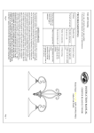
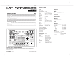
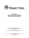
st-24m series
12 pan pressureless steam cookers
parts and service manual
Effective august 13, 2014
Superseding All Previous Parts Lists.
The Company reserves the right to make substitution in the event that items specified are not available.
ERRORS: Descriptive and/or typographic errors are subject to correction.
MARKET FORGE INDUSTRIES
44 Lakeside Avenue, Burlington, Vermont 05401 USA Telephone: (802) 658-6600 Fax: (802) 860-3732
www.mfii.com
P/N 14-0290 Rev A (8/14)
Table of Contents
Principles of Operation. . . . . . . . . . . . . . . . . . . . . . . . . . . . . . . . . . . . . . . . . . . . . . . . . . . . . . . . . . . 3
Troubleshooting.. . . . . . . . . . . . . . . . . . . . . . . . . . . . . . . . . . . . . . . . . . . . . . . . . . . . . . . . . . . . . . . . . . 5
wiring diagrams. . . . . . . . . . . . . . . . . . . . . . . . . . . . . . . . . . . . . . . . . . . . . . . . . . . . . . . . . . . . . . . . . . . . 9
repair and replacement. . . . . . . . . . . . . . . . . . . . . . . . . . . . . . . . . . . . . . . . . . . . . . . . . . . . . . . . . 12
illustrated part list
control panel assembly. . . . . . . . . . . . . . . . . . . . . . . . . . . . . . . . . . . . . . . . . . . . . . . . . . . . . . . . . 13
cabinet assembly. . . . . . . . . . . . . . . . . . . . . . . . . . . . . . . . . . . . . . . . . . . . . . . . . . . . . . . . . . . . . . . . . 14
door assembly. . . . . . . . . . . . . . . . . . . . . . . . . . . . . . . . . . . . . . . . . . . . . . . . . . . . . . . . . . . . . . . . . . . . 16
door latch and handle. . . . . . . . . . . . . . . . . . . . . . . . . . . . . . . . . . . . . . . . . . . . . . . . . . . . . . . . . . 17
condenser assembly. . . . . . . . . . . . . . . . . . . . . . . . . . . . . . . . . . . . . . . . . . . . . . . . . . . . . . . . . . . . . 18
august 13, 2014
2st-24m series convection steamers
Principles of Operation
GENERAL
The ST-24 Pressureless Steam Cooker consists of two
identical cooking compartments, one above the other, in
a single cabinet assembly. Each compartment is fitted
with independent electrically controlled steam circuits and
spring-loaded, self-sealing doors with slam action latches.
Compartments can be used separately or simultaneously
for either constant steam or 60-minute timing. The principles of operation in this section include an explanation
of steam, steam condensing, and electrical circuits and
their functioning.
PLUMBING CIRCUITS
The plumbing circuits consist of the piping, steam solenoid valves, orifice, drain, and cold water condenser required to provide controlled steam application to the cooking compartments. A simplified diagram of these circuits
is shown in below
NOTE: Figure 1 is strictly a pictorial schematic diagram
and is not intended to show the actual configuration of the plumbing. All components are shown
in correct relationship with each other. However,
the diagram does not show their actual locations
or position within the cooker.
As shown in the diagram, steam inlet and exhaust connections are connected at the factory directly into a steam
boiler or direct-connected steam plumbing enclosed
within the base cabinet on which the cooker is mounted.
The boiler (or direct-connected steam control system) is
equipped to supply constant, regulated steam at 14–15
PSI. Steam exhaust, having been reduced to water by the
cold water condenser, is directed into the boiler (or directconnected steam control) drain system.
Steam inlet lines for compartments are equipped with
normally closed solenoid valves operated by the electrical control circuits. The inlet valves are opened whenever
the compartment control circuit is activated by use of the
60-minute timers.
Steam Inlet Line
A steam supply line is plumbed from the boiler output (or
direct-connected steam control) to a 1/2-inch barb fitting
connected to the input sides of both steam inlet solenoid
valves. When a cooking compartment is not in use, the
valve for the compartment remains closed to prevent
steam from entering. During operation, the appropriate
inlet solenoid valve is opened by activation of the control circuit. Steam is projected onto the surface of pans
of food loaded into the compartment by an orifice located
inside the compartment. Steam continues to flow through
the compartment in this manner until the control circuit
closes the solenoid valve.
Figure 1
august 13, 2014
3st-24m series convection steamers
Principles of Operation
Steam Exhaust and Drain Lines
Perforated strainers at the drain line openings inside each
compartment allow only steam, condensation, and liquid
cooking drainage to enter. Prior to discharge into the boiler drain system, steam is converted to water by the cold
water condensing systems for each compartment.
Steam Exhaust Condensing System
The steam condensing system consists of the identical,
two-position, normally closed cold water solenoid valves,
with outlet sides connected into the exhaust plumbing for
each cooking compartment. A spray nozzle directs cold
water about the inside of the drain lines to increase cold
water contact with exhausted steam. Valve inlet sides
are connected remote from the supply line of the steam
boiler (or direct-connected steam plumbing). The valves
respond to a thermostatic switch located inside the compartment. When the timer starts the cold water solenoids
will energize.
ELECTRICAL CIRCUITS
The electrical circuits of the cooker control the power to
activate timer motors and energize solenoid-operated
valves and circuits, which in turn control application of
steam to the cooking compartment and condensation
of steam from the exhaust line. The cooker operates on
120V, 2 amp, 60Hz electrical service connected to all circuits from the circuits of the steam boiler (or direct-connected steam controls) contained within the cabinet on
which the cooker is mounted. Power is supplied to the
control circuit at all times when the shut-off device (Circuit
Breaker) for the unit (installed by a certified Electrician) is
in the ON position.
Control Circuit Components
A brief description of the electrical circuit elements follows.
60 Minute Timer/Constant Steam
The timer contains a 120-volt AC synchronous motor that
drives a timing dial through a gear reduction and clutch
mechanism. The timer dial is manually set for any interval
of operation from 0 to 60 minutes or constant steam as
read on the calibrated dial face. The manual rotation of
the dial moves the common element (1) of the timer switch
from the neutral (OFF) position to contact (3), which connects with the steam inlet solenoid valve operating circuit.
The cooker is placed into automatic operation with the
setting of the timer dial. Its timing cycle, however, is automatically delayed by a thermostatic switch, which assures
operating temperature is achieved before the timer motor
begins to “time out.” When the timer motor has operated
for the preset duration, the common element is transferred to contact (4), returning the inlet solenoid valve to
august 13, 2014
the closed position and energizing the buzzer. Contact to
the buzzer circuit remains closed until the dial is manually turned to the OFF position, returning the common element (1) of the timer switch to the neutral position.
Indicator Lights
An indicator light is included for both compartments. The
light remains on (red) at all times when the coinciding timer dial is set and the door interlock switch is closed. The
light turns off at the end of the timed cooking duration or
when the set time has elapsed.
Buzzer
The buzzer is an alarm device that operates by oscillation
of a striker against the core of an electromagnet. When
the 60-minute timer dials reach the “0-Minute” position,
the buzzer coil is energized to sound the buzzer. Movement of the timer dial to the OFF position opens the contact to the buzzer coil to shut it off.
Door Interlock Switch
The interlock switch is a single-pole proximity switch with
normally open contacts. The switch is operated by the
proximity of a magnet within the door. When the door is
open, the switch contacts remain in the open position.
When the door is closed and securely latched in place,
the magnet is near the switch to close the contacts.
Connected between the operating contact (3) of the timers and the steam inlet solenoid valve, the door switch
acts as a protective device to interrupt valve operation
unless the door is closed.
Thermostatic Switch
The thermostatically operated switch is a two-position,
normally open switch mounted on the cooking compartment. The switch functions to activate the cold water solenoid valves of the steam condensing system and to delay
timer motor operation until the compartment temperature
reaches 195°F, thus assuring that cooking temperature
exists throughout the timed duration.
Digital Timers (Optional)
The timer controls the steam to the cavity by either a constant steam setting or a used defined timer that will be
programmed by the user into the timer
Kettle Switch (Optional)
The Kettle Switch will allow the user to set the mode of the
steam. The user can either set the switch so that top and
bottom cavity are in use at the same time. Or the bottom
cavity and a separate direct connected kettle can be used
at the same time.
4st-24m series convection steamers
Troubleshooting
Trouble-Shooting Guide
The electrical trouble-shooting procedures that follow require access to components and terminals of the electrical control panel. Electrical controls are reached by removing screws that fasten the control panel to the frame.
The panel may be pulled forward for testing while interconnected to the cooker circuits or disconnected at the
pin connection for complete removal and repair.
A trouble-shooting guide for use by service personnel is
given in the table below.
Electrical Fault Isolation
Correction of an electrical failure first requires isolation of
the fault to a single circuit or component. In most cases,
the nature of the failure and its effect upon the operation
of the cooker will be sufficient to narrow it down to one or
more circuit elements. The Electrical Fault Isolation table
is provided as a guide for isolating electrical faults.
Incoming Power
Before trouble-shooting any of the electrical parts or assemblies, verify that power is being supplied to the cooker. Incoming power is connected at the boiler (or directconnected steam) control box located in the base cabinet.
With power connected to the cooker, an AC voltmeter is
used to measure 120 volts across L1 and L2. If 120 volts
is present, and the cooker will not operate, the fault lies
within the electrical circuits of the cooker.
Electrical Trouble-Shooting Procedures
Before performing the trouble-shooting procedures in this
section, the serviceman must be familiar with the function
of all controls as described in the Operation section as
well as with the Principles of Operation.
ELECTRICAL FAULT ISOLATION GUIDE
FAILURE
FAULT LOCATION
1. Will not operate in either CONSTANT STEAM or 60-MINUTE TIMER positions.
2. Operating in CONSTANT STEAM position but not in 60-MINUTE TIMER
position.
3. Operates in 60-MINUTE TIMER position but not in CONSTANT STEAM
position.
4. Steam solenoid valve fails to open with indicator light on.
5. Indicator light off when steam solenoid valve open.
6. With indicator light on and steam solenoid valve open, timer dial fails to
turn.
7. Buzzer fails to sound at end of 60-MINUTE TIMER mode.
8. Steam flows continuously from boiler drain line.
august 13, 2014
a.
b.
c.
d.
a.
b.
a.
b.
a.
b.
a.
b.
a.
b.
c.
d.
a.
b.
c.
a.
b.
c.
Incoming power
Timer
Door interlock switch
Wiring
60-minute timer
Wiring
Timer
Wiring
Solenoid valve coil
Wiring
Indicator light
Wiring
Compartment thermostatic switch
Constant steam position
Timer motor
Wiring
60-Minute timer contacts
Buzzer
Wiring
Thermostatic switch
Cold water solenoid valve
Wiring
5st-24m series convection steamers
troubleshooting
Electrical Inspection
To confirm timer motor condition, proceed as follows:
The first step in any electrical trouble-shooting procedure
is a thorough physical inspection of all wiring connections.
To access electrical components, remove the control panel as explained in Exterior Panel Removal.
1. Carefully check motor wire leads and tighten loose
connections.
warning
Before removing control panel or checking
connections and wiring, be sure that the circuit breaker for incoming power is OFF. When
power is supplied, all exposed terminals of the
control panel carry 120 volts.
Check all wiring connections by hand to assure that both
ends of all connection points are tightly secured. Use a
screwdriver to tighten connection points. If necessary, visually inspect all quick-disconnect terminals for evidence
of corrosion. Terminals in this condition should be separated, cleaned with emery cloth until shiny, and tightly reconnected.
60 Minute Timer
Timer Contacts
Defective timer contacts will result in failure of either cooker compartment to operate. When this occurs, remove the
control panel (see Exterior Panel Removal), and proceed
as follows:
warning
Use care while working with control panel.
Terminals carry 120 volts.
2. Turn on power to the cooker.
3. Set timer dial (any setting beyond “0-Minute”). If operation is correct, the motor will turn the dial toward
“0-Minute.” If the motor fails to operate, it is defective
and the entire timer must be replaced.
4. Shut off power to the cooker.
Door Interlock Switch
Malfunction of the cooker door interlock switch prevents
timer indicator lights from turning on and steam solenoid
from opening when the timer dial is set. If steam does not
enter the compartment and the indicator light fails to turn
on with the door latch securely engaged, the fault may be
in the door interlock switch. Proceed as follows:
1. Turn off power to the cooker.
2. Disconnect wires to the door switch terminals.
1. Turn off power to the cooker at external circuit breaker.
3. Connect an ohmmeter between the terminals of the
switch.
2. Disconnect all five wires from timer terminals
4. Actuate the switch by closing the cooking compartment door. If a zero reading cannot be obtained, the
switch is defective and must be replaced.
3. Connect an ohmmeter between terminals 1 and 3.
4. Rotate timer dial beyond the “0-Minute” point (any
setting) to obtain a reading of zero ohms on the
ohmmeter. If zero ohm reading cannot be obtained,
timer contacts are defective and the timer must be
replaced.
5. Move ohmmeter leads to terminals 1 and 4.
6. Rotate timer dial to “0-Minute” position (an audible
click indicates correct position). If zero ohm reading
cannot be obtained, the timer is defective and must
be replaced.
7. Remove ohmmeter and replace all five leads on timer
terminals.
5. Remove the ohmmeter and replace the leads on
switch terminals.
Steam Solenoid Valves
When either inlet solenoid valve fails to operate, the fault
may be a defective coil. A defective coil is found using an
AC volt-meter to check the voltage at the coil wire terminals, with the cooker compartment operating in either
CONSTANT STEAM or 60-MINUTE TIMER mode. If voltage of 120 volts is present and the coil fails to open the
valves, the fault is in the valve coil. Defective valve coils
are not separately replaceable, requiring complete valve
replacement.
Timer Motor
A defective timer motor will cause continuous operation in
the TIME mode, with the timer dial failing to return to the
“0-Minute” position. Since thermostatic switch failure can
cause the same symptom, fault must first be isolated to
the timer by testing the thermostat.
august 13, 2014
6st-24m series convection steamers
troubleshooting
Indicator Lights
Cold Water Condenser Circuit
If the cooker compartment functions correctly, with the
single exception that the indicator light fails to light during
operation, the fault is a defective indicator light. A “burned
out” or defective light is verified by using an AC volt-meter
at the leads, with input power on the selector switch in the
correct position for that timer, the timer set, and the door
latches closed. If 120 volts is present, the fault is in the
indicator light and requires replacement. If 120 volts is not
present, the fault is in the wiring or control components
(selector switch, timer, or door switch).
If during cooker operation steam exits from the drain
line opening (located in lower boiler compartment) and
the condensing system fails to operate, as evidenced
by repeated discharge of water from the drain line, the
condensing circuit is malfunctioning. The failure can be
caused by a defective condenser thermostat or cold water solenoid coil, or by wiring failure. To test condenser
thermostat, refer to Cooking Compartment Thermostatic
Switch.
Cooking Compartment Thermostatic Switch
A thermostatic switch included in the circuit for the timer
motor delays timer operation until steam flowing into the
compartment satisfies the temperature-actuated switch
device. If a timer motor fails to operate within about one
minute after the indicator light comes on (with cooker
compartment empty), the cause may be a defective thermostatic switch. To test the switch, proceed as follows:
1. Disconnect the two wires connected to the thermostatic switch terminals.
2. Connect an ohmmeter between the two terminals of
the switch.
3. Place the cooker into operation and observe ohmmeter dial. Within one minute of operation, the switch
contacts close automatically to register a zero ohm
reading on the dial. If a zero ohm reading is not obtained, the switch is defective.
4. Shut off cooker, disconnect ohmmeter leads, and replace wires on switch terminals.
Buzzer
If the buzzer does not sound at the termination of the operator-selected timer setting (timer dial returned to “0-Minute” position), the fault may be a defective buzzer. Buzzer
operation is verified using an AC volt-meter at buzzer coil
connections with input power on and selector switch and
coinciding timer dial set at the “0-Minute” position. If voltage is 120 volts, the fault is in the buzzer, which must be
replaced. If 120 volts is not present, the fault is in the wiring or control components (timer or selector switch).
august 13, 2014
If the condenser thermostat functions correctly, but either of the cold water solenoid valves fails to operate, the
cause might be a faulty valve coil. A defective coil is found
using an AC volt-meter to check the voltage at the coil
wire terminals with the cooker compartment in operation.
If voltage of 120 volts is present and the valve fails to
open, the fault is in the valve coil. Defective valve coils are
separately replaceable.
Wiring
All of the electrical components of the cooker (timers, indicator lights, etc.) are connected to each other by wiring.
If all of the electrical components are operating correctly (and the incoming power has been checked), but the
cooker fails to operate, the fault lies in the wiring.
The Wiring Diagrams in this manual show all terminals
and interconnections within the electrical circuits. All numbered terminals are identified and all leads number coded
as shown. Connections can be easily removed.
The Schematics show the same information schematically and is an aid in isolating circuits for testing. Using
an ohmmeter, wiring continuity between the connections
shown on the wiring diagram is readily verified. This is
best done in stages, removing only those wires required
for each continuity check. As each lead is replaced, it
should be checked for evidence of corrosion, and cleaned
if necessary. All leads must be tightly attached so as to
provide a good electrical connection.
7st-24m series convection steamers
troubleshooting
GENERAL TROUBLESHOOTING GUIDE
PROBLEM
PROBABLE CAUSE(S)
1. Indicator light fails to light with timer a. Power to cooker off.
set.
a.
b. Door interlock switch contacts b.
not closed.
c. Door interlock switch faulty.
c.
d. Indicator light burned out.
e. Faulty timer contacts.
d.
e.
f.
f.
Faulty wiring.
2. Steam fails to enter cooking compart- a. Faulty steam solenoid valve.
ment with indicator light on.
b. Faulty wiring.
a.
3. Steam enters compartment continu- a. Constant steam position.
ously. Timer dial not turning.
b. Faulty thermostatic switch.
a.
b.
b.
c. Faulty timer motor.
c.
d. Faulty steam solenoid valve.
d.
e. Faulty wiring.
e.
4. Steam continues to flow into compart- a. Timer contacts faulty.
ment and/or buzzer fails to sound at b. Buzzer faulty.
end of timer setting.
c. Faulty wiring.
a.
b.
c.
5. Steam flows continuously from boiler a. Cold water not connected.
(or direct connected steam control) b. Faulty thermostat.
drain line with cooker in operation.
a.
b.
c. Faulty cold water solenoid.
d. Faulty wiring.
c.
d.
august 13, 2014
REMEDY
Locate external circuit breaker for
incoming power and place in ON
position.
Shut cooker door to close switch
contacts. Check alignment of door
with switch.
Replace switch. See Door Interlock
Switch.
Replace light.
Replace timer. See 60-Minute Timer.
Inspect condition of wire and tightness of all connections. Correct as
needed.
Replace valve. See Steam Solenoid
Valves.
Inspect condition of wire and tightness of all connections. Correct as
needed.
Move knob to timing location.
Replace switch. See Cooking Compartment Thermostatic Switch.
Replace timer. See 60-Minute Timer.
Replace valve. See Steam Solenoid
Valves.
Inspect condition of wire and tightness of all connections. Correct as
needed.
Replace timer. See 60-minute timer.
Replace buzzer. See Buzzer.
Inspect condition of wire and tightness of all connections. Correct as
needed.
Turn on external shut-off valve.
Replace thermostat. See Cooking
Compartment Thermostatic Switch.
Replace valve.
Inspect condition of wire and tightness of all connections. Correct as
needed.
8st-24m series convection steamers
wiring diagrams
mechanical controls
august 13, 2014
9st-24m series convection steamers
wiring diagrams
digital controls
august 13, 2014
10st-24m series convection steamers
wiring diagrams
ladder diagram
august 13, 2014
11st-24m series convection steamers
repair and replacement
caution
UNDER NO CIRCUMSTANCES SHOULD
HARDWARE (OR PARTS) BE REPLACED
WITH A DIFFERENT LENGTH, SIZE, OR TYPE
OTHER THAN AS SPECIFIED IN THE PARTS
LIST. THE HARDWARE USED IN THE COOKER
HAS BEEN SELECTED OR DESIGNED SPECIFICALLY FOR ITS APPLICATION, AND THE
USE OF OTHER HARDWARE MAY DAMAGE
THE EQUIPMENT AND WILL VOID ANY WARRANTY.
Door Latch Tension Adjustment
caution
SHUT OFF MAIN ELECTRICAL POWER TO
UNIT!
Procedure:
1. Open the cooking compartment door.
2. Remove the control panel by removing the eight
mounting screws and disconnecting the wire plug and
restraining wire.
3. Tighten both nuts down until the springs are fully
compressed.
4. Back each nut off 1/2 turn.
5. Remount the control panel, reconnecting wire plug
and restraining wire.
Door Handle Tension Adjustment
Procedure:
1. Open the cooking compartment door.
2. Remove the six screws and washers from the top
edge and bottom edge of the door.
Procedure - Replace Gasket:
1. Open the cooking compartment door.
2. Remove the six screws on the outside of the door,
and remove the inner door assembly.
3. Remove the eight nuts from the door gasket mounting plate on the inside of the inner door assembly.
4. Remove the door gasket mounting plate and the door
gasket.
5. Install the new door gasket to the mounting plate.
6. Reassemble the mounting plate with gasket to the inside of the inner door assembly using the eight nuts.
7. Reassemble the inner door assembly using the six
screws on the outside of the door.
NOTE: Remember that the lip on the door gasket mounting plate must fit into the channel on the inside
edge of the gasket to insure a proper seal.
Procedure - To Adjust Gasket to Unit:
To prevent steam leaks around the door, adjust the gasket
tension to cavity. Adjust the gasket by loosening the six
screws on top and bottom of door, move inner door plate
in or out, left side or right side, and tighten the six screws.
Exterior Panel Removal
warning
To prevent hazard in servicing the cooker, be
certain that the steam supply boiler is shut
down, the cold water shut-off valve is closed,
and the electrical disconnect circuit breaker
for the cooker/boiler unit is off before removing side panels.
4. Tighten both nuts down until the springs on the outer
door are fully compressed.
Access to all internal plumbing and electrical assemblies
is from the right side and right front. The left-side panel is
removed by removing the bottom screw and pushing up
on the panel until the lower lip disengages the frame. The
electric control panel may also be removed as a unit by
removing screws and pulling the panel forward. Removal
of the control panel is completed by unplugging interconnecting wiring at the pin housing.
5. Back each nut off 1/2 turn.
Steam and Water Solenoid Valve Replacement
6. Remount the inner door gasket mounting plate assembly by assembling the six screws and washers.
Replacements for the 1/2-inch steam solenoid valves and
the 1/4-inch water valves are available as complete units
from Market Forge Authorized Service Agencies. It is necessary to replace an entire steam valve when the coil is
faulty or the diaphragm ruptures. Replacement coils are
available for the water valves. The valves are accessed
as explained in Exterior Panel Removal shown above.
3. Remove the inner door gasket mounting plate assembly from the outer door. Do not disassemble these
three components—remove them as an assembly.
Door Gasket Replacement
The cooking compartment door gaskets are made of a
silicone-type rubber material that is very durable but subject to wear during normal operation. Should the gasket
leak, readjust the door gasket to the unit or replace it.
august 13, 2014
12st-24m series convection steamers
control panel assembly
item
part no.
1
98-1616
CONTROL PANEL
1
2
98-1612
LEXAN, CONTROL PANEL
1
3
08-6464
60-MINUTE TIMER
2
4
08-6541
TERMINAL STRIP
2
5
91-6471
BRACKET, TERMINAL STRIP
2
6
10-7395
BUZZER
2
7
08-3826
KNOB, TIMER
2
8
10-5052
LIGHT, RED
2
august 13, 2014
description
qty
13st-24m series convection steamers
cabinet assembly
august 13, 2014
14st-24m series convection steamers
cabinet assembly
item
part no.
description
qty
1
08-6308
REED SWITCH
2
2
08-4912
ASSEMBLY, PLUMBING DRAIN
2
3
10-2793
REAR POST
2
4
98-1643
COUPLER, 1/2” NPT X 5/8” ID BARB
4
5
08-6538
ELBOW, 90O, 1/2“ IPS
4
6
98-1643
BRACKET, REAR FRAME SUPPORT
1
7
08-6538
CHECK VALVE, 3/8 OD BLACK
2
8
91-6491
GROMMET, SILICONE RED
2
9
91-7639
BRACKET, CAVITY SUPPORT
1
10
91-7318
WELD ASSEMBLY, TOP
1
11
10-9174
RELAY, TUBE
4
12
10-9175
RELAY, BASE
4
13
91-6940
BRACKET, RELAY
2
14
91-6475
HINGE, ASSEMBLY TOP
2
15
91-6476
HINGE, ASSEMBLY BOTTOM
2
16
91-7334
TROUGH, DRIP ST-24
1
17
91-7385
ASSEMBLT, DOOR ST-24
2
18
91-5621
ASSEMBLY, JET PIPE
4
19
91-6492
LATCH, DOOR
2
20
08-4600
SPRING, COMPRESSION
4
21
98-1637
MECHANICAL CONTROL PANEL WITH SWITCH
1
22
91-7684
STRAINER, CAVITY
2
23
98-1605
WELD ASSEMBLY, MIDDLE RACK
2
24
91-7699
RACK SIDE
4
25
10-4586
NUT, 1/2“ IPS, S.S.
6
26
10-8105
THERMOSTAT, SNAP DISC, PROBE TYPE
2
27
10-3343
NUT, BRASS, 1/2“ IPS
2
28
10-1956
SCREW, TAPTIGHT, 8-32 X 3/8“
20
29
10-2571
NUT LOCK, 8-32
17
30
08-1204
PLUG, HOLE WHITE
4
31
10-2184
SCREW, HEX HEAD, 10-32, 3/4“ LG
8
32
91-7569
PANEL, SIDE
2
33
91-7327
PANEL, REAR
1
34
98-1632
INSULATION, FRONT
1
35
98-1631
INSULATION, REAR
1
36
08-7959
TUBING, NORPRENE 3/8” ID
*
37
08-7960
TUBING, NORPRENE 5/8” ID
*
38
98-1638
MECHANICAL CONTROL PANEL WITHOUT SWITCH
1
39
98-1639
DIGITAL CONTROL PANEL WITH SWITCH
1
40
98-1640
DIGITAL CONTROL PANEL WITHOUT SWITCH
1
41
08-2702
BUSHING, DOOR, WHITE
4
42
91-7690
BRACKET, REED SWITCH
2
* AS MEASURED.
august 13, 2014
15st-24m series convection steamers
door assembly
item
part no.
description
qty
1
91-7386
OUTER DOOR
1
2
91-7387
INNER DOOR
1
3
91-7388
GASKET RETAINING PLATE
1
4
91-7389
DOOR GASKET
1
5
91-5745
DOOR HANDLE
1
6
09-1608
STRIKER
1
7
08-5027
MAGNET
1
8
91-5901
MAGNET BRACKET
1
9
08-4600
COMPRESSION SPRING
2
august 13, 2014
16st-24m series convection steamers
door latch and handle
item
part no.
1
91-5669
LATCH (OLD VERSION)
2
2
91-6734
HANDLE (OLD VERSION)
2
3
91-5745
HANDLE (NEW VERSION)
2
4
91-6492
LATCH (NEW VERSION)
2
august 13, 2014
description
qty
17st-24m series convection steamers
condenser assembly
item
part no.
description
qty
1
10-5859
VALVE, STEAM SOLENOID
1
2
08-4892
COUPLER, BRASS 3/8 OD X 1/2 THRD NPT
2
3
10-2885
UNION, FEMALE 1/2 IPS
1
4
10-2849
NIPPLE, CLOSE 1/2” NPT BRASS
2
5
98-1477
COUPLER, BRASS, BARB 3/8” X 3/8” NPT
1
6
08-6581
TEE, MALE 1/2” NPT X FEMALE 1/2“ BRANCH
1
7
10-3739
1/2” X 3/8 REDUCING BUSHING
1
8
98-1630
WELDMENT, COLD H20 STEAM VALVE
1
9
10-1055
TEE, 3/8” ALL ROUND
1
10
10-3644
PLUG, SQUARE HEAD 3/8” IPS, BRASS
1
11
08-7525
MIPPLE, CLOSED 3/8” NPT, BRASS
2
12
08-6498
VALVE, 3/8” NPT, COLD WATER CONDENSER
1
13
08-4912
COUPLER, BARB 5/8” OD X 1/2“ IPS
1
14
08-7962
COUPLER, BARB 5/8” OD X 3/8“ IPS
1
15
98-1477
COUPLER, BRASS BARB 3/8” X 3/8“ THD NPT
1
august 13, 2014
18st-24m series convection steamers