1
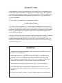
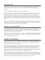
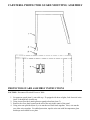
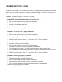
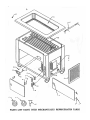
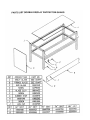
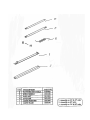
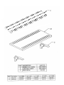
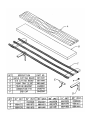
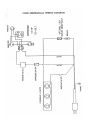
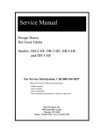
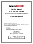
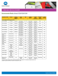
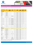
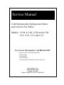
Service Manual
Cold Mechanically Refrigerated Tables
and Cold Ice Pan Tables
Models: 3-CM, 4-CM, 5-CM and 6-CM
3-CI, 4-CI, 5-CI and 6-CI
For Service Information, Call 800-544-3057
Please provide the following information:
- Model number
- Serial number
- Date of purchase
- Part description and number as shown in parts list
Piper Products, Inc.
300 South 84th Avenue
Wausau, WI 54401
Phone: 715-842-2724 / Fax: 715-842-3125
INTRODUCTION
Congratulations: You have just purchased one of the finest pieces of equipment on the
market today. Before installing or operating your new Piper Products, Inc. equipment,
you should read through this manual. This manual should be retained for further reference as it contains installation and operating instructions, service tips, part lists and
warranty information.
For your safety, read and follow all cautions and warnings.
Freight Damage Claims:
Your Piper Products equipment was carefully inspected and packed before leaving our
factory. The transportation company assumes full responsibility for safe delivery of this
equipment. Piper Products cannot assume responsibilities for damage or loss incurred in
transit. Visible damage or loss should be noted on the freight bill and signed by the
person making the delivery.
A freight claim should be filed immediately with the transportation company. If damage
is unnoticed or concealed until equipment is unpacked, notify the transportation
company immediately and tell them you want to file a concealed damage claim. This
must be done within ten (10) days after delivery was made. Be sure to retain all packing material and cartons.
WARNING
Installation of this equipment should be done only by persons qualified or licensed
to install electrical equipment.
Adjustments and service work should be performed only by a qualified service
technician. Service is available through Authorized Piper Products Parts and
Service Distributors throughout the United States. For a complete listing of these
call or write Piper Products, Inc. for the name of the nearest distributor.
This equipment is intended for commercial use only. Not for household use.
Use of other than genuine Piper Products replacement parts or service work
performed by other than an authorized Piper Products service agent will void the
warranty.
Do not use any corrosive cleaners. Use only cleaners approved for stainless steel.
INSTALLATION
Carefully remove carton or crate from unit. Remove all loose packing materials, making sure that no
small parts or accessories are lost. Inspect unit for concealed damage before discarding packing
materials.
It is the responsibility of the installer to comply with all local codes.
Install the protector guard. Installation instructions for the different model protector guards are found
on pages 4, 5 and 6 of this manual. Refer to these for installation details. If protector guard is
equipped with lights, be sure that the protector guard light switch located at the end of the protector
guard is turned off. For mechanically refrigerated units make sure that the switch in the control panel
is turned off. Connect the electrical power cord and NEMA 5-15P plug to a 120 volt 15 AMP power
source.
Remove the access panels to the condensing unit and check that the fan turns freely and the condenser
is not blocked. The service valves have been opened at the factory and the pressure control is pre-set
to the proper temperature and should need no further adjustment.
START-UP AND OPERATION
When installing unit, make sure there is a minimum 2” of air space to allow free air flow into the
louver panel located on the end of the unit. Also allow 12” of free air space for the louvered panels
located in the front and in the rear of the cabinet.
Turn the switch in the control panel to the “ON” position. The pilot light will light and the condensing
unit will start. Allow the unit to run for about 15 minutes. The bottom of the cold pan should start to
frost over and should be cold to the touch.
THEORY OF OPERATION
The Cold Ice Pan Food Table (CI) is designed to be used with ice to display cold foods and salads
during the meal period. There is no mechanical refrigeration used. Ice is packed around food pans
placed into the food well to provide cooling. A one-inch drain valve is provided for draining excess
water from melted ice and for ease of cleaning.
The Mechanically Refrigerated Cold Food Table (CM ) is designed to be used with or without ice to
display cold foods and salads during the meal period. The mechanical refrigeration system uses a 1/3
horsepower compressor and thermostat control to provide cooling to copper coils mounted to the
bottom of the food well. Crushed ice should be used along with the mechanical refrigeration system to
achieve the optimum control of food temperatures over longer periods of time.
NOTE: Cold Food Tables are NOT refrigerators and will NOT keep food cold for long periods of
time. Food should always be placed into the table directly from the refrigerator at as low of a temperature as possible. When the food in the table reaches a temperature of 38° to 40° Fahrenheit it should
be placed back into the refrigerator and replaced with cold food from the refrigerator.
BUFFET PROTECTOR GUARD MOUNTING ASSEMBLY
PROTECTOR GUARD ASSEMBLY INSTRUCTIONS
CAUTION: Disconnect Electrical Power to Table.
1. Set protector guard (item 1) onto table top. If equipped with heat or lights, feed electrical wires
(item 2) through hole in table top.
2. Using screws provided, attach protector guard to brackets (item 3).
3. Remove the cover plate located on the end of the unit in the center of the panel.
4. Using wire nuts provided (item 4), wire nut the two black leads together. Next, wire nut the
two white wires together. For added protection, tape the wire nuts with hi-temperature glass
braid tape and reinstall cover plate.
CAFETERIA PROTECTOR GUARD MOUNTING ASSEMBLY
PROTECTOR GUARD ASSEMBLY INSTRUCTIONS
CAUTION: Disconnect Electrical Power to Table.
1. Set protector guard (item 1) onto table top. If equipped with heat or lights, feed electrical wires
(item 2) through hole in table top.
2. Using screws provided, attach protector guard to brackets (item 3).
3. Remove the cover plate located on the end of the unit in the center of the panel.
4. Using wire nuts provided (item 4), wire nut the two black leads together. Next, wire nut the
two white wires together. For added protection, tape the wire nuts with hi-temperature glass
braid tape and reinstall cover plate.
CAFETERIA DOUBLE DISPLAY MOUNTING ASSEMBLY
PROTECTOR GUARD ASSEMBLY INSTRUCTIONS
CAUTION: Disconnect Electrical Power to Table.
1. Set protector guard (item 1) onto table top. If equipped with heat or lights, feed electrical wires
(item 2) through hole in table top.
2. Using screws provided, attach protector guard to brackets (item 3).
3. Remove the cover plate located on the end of the unit in the center of the panel.
4. Using wire nuts provided (item 4), wire nut the two black leads together. Next, wire nut the
two white wires together. For added protection, tape the wire nuts with hi-temperature glass
braid tape and reinstall cover plate.
OPERATION OF COLD ICE PAN FOOD TABLE (CI)
A. Make sure that the well is empty and clean and that the drain valve is closed.
NOTE: Crushed ice should be used as it will pack around the food pans better and give more efficient
cooling than cubed ice.
B. Place about two inches of ice on the bottom of the well. Never place food directly into the
well. Using four-inch deep food pans place pans of pre-refrigerated food into the well on top of
the ice leaving about 2 inches between pans. Pack ice completely around food pans filling well
to the top with ice.
C. Food pans should be kept covered when possible. Food should be stirred often and pans of
food should be changed if the temperature reaches 40° Fahrenheit or above.
D. As the ice melts, new ice should be added around and under the food pans.
E. Excess water should be drained off by placing a bucket under the drain pipe and opening the
drain valve. Be sure to close the drain valve before removing the bucket.
F. Always drain or remove water from the well after each meal. Place a bucket under the drain
pipe and open drain valve. When bucket is full, close drain valve and empty bucket. Repeat
this until the well is drained.
OPERATION OF MECHANICALLY REFRIGERATED COLD FOOD
TABLE (CM)
A. Make sure that the well is empty and clean and that the drain valve is closed.
NOTE: Crushed ice should be used as it will pack around the food pans better and give more efficient
cooling than cubed ice.
B. Turn the master switch in the control panel "ON" to start mechanical refrigeration system. Place
about 2 inches of crushed ice on the bottom of the well then cover the well and allow unit to
pre-cool for approximately 30 minutes.
C. Uncover well and add additional crushed ice until at least 2 inches of ice covers the bottom of
the well. Never place food directly into the well. Using four-inch deep food pans, place pans
of pre-refrigerated food into the well on top of the ice making sure that pans fit tightly together.
Do NOT leave any open space between food pans. Cover all open spaces or fill with crushed
ice.
D. Food pans should be kept covered when possible. Food should be stirred often and pans of
food should be changed if the temperature reaches 40° Fahrenheit or above.
E. With the mechanically refrigerated system operating less ice will be required, but as the ice
melts new ice should be added around and under the food pans.
F. Excess water should be drained off by placing a bucket under the drain pipe and opening the
drain valve. Be sure to close the drain valve before removing the bucket.
G. Always drain or remove water from the well after each meal. Place a bucket under the drain
pipe and open drain valve. When bucket is full, close drain valve and empty bucket. Repeat
this until the well is drained.
MAINTENANCE
Piper equipment is constructed with the best quality materials and is designed to provide you with
durable service when treated with ordinary care. To obtain the best performance from your equipment,
it should be cleaned daily and maintained in good condition.
CAUTION: Prior to cleaning or maintenance, turn all switches "OFF" and disconnect the power cord
from the receptacle.
WARNING: Do not use any chlorinated or highly caustic cleaners, acids, ammonia or other corrosive
cleaners. These may cause corrosion and/or damage to the stain less steel well. Use only cleaners
approved for stainless steel. Do no allow water to stand in wells for long periods of time. Water must
be removed from well and the well cleaned after every serving period.
GENERAL CLEANING
CAUTION: Use only cleaning agents approved for aluminum and stainless steel. Do NOT use
chlorinated cleaners.
A. Clean the well using a soft cloth or sponge with a mild detergent. Rinse completely with warm
water and then dry.
B. A plastic scouring pad and a mild detergent may be used to remove any hardened food or scale
deposits.
NOTICE: Do NOT use steel wool to clean wells.
C. Use a soft cloth or sponge with a mild detergent to clean all exposed surfaces of the table.
Rinse completely with warm water and dry.
CAUTION: The louvered panels may have sharp edges and could cause injury. Do NOT run fingers
along edges and use gloves when cleaning.
D. Wipe the cord and plug using a cloth with detergent and warm water. Do NOT use excessive
water.
CLEANING ACRYLIC PROTECTOR GUARDS
WARNING: Do NOT use window cleaning sprays, kitchen scouring compounds or solvents such as
acetone, gasoline, benzene or lacquer thinner.
A. Use a soft cloth and mild detergent with plenty of lukewarm water to clean protector guards.
B. Rinse thoroughly with lots of water and dry by blotting with a damp cloth or chamois.
C. Protect and maintain the surface gloss by occasionally waxing with a good paste wax. Apply a
thin even coat with a soft clean cloth and polish with cotton flannel. Wipe with a damp cloth
to help eliminate electrostatic charges.
D. Fine scratches can be removed by hand polishing. Apply a compound such as Simonize cleaner
to a soft flannel pad and rub. When the scratches have disappeared, remove all residue and
polish.
CLEANING CONDENSING UNIT (CM)
It is very important for proper performance and condenser longevity to keep the condenser clean.
EVERY MONTH:
A. DANGER: Disconnect electrical power to the cooler by turning master switch to the “OFF”
position and unplugging cooler from electrical receptacle.
B. Remove the louvered panels from the condensing unit compartment.
C. Clean condenser by using a brush and vacuum cleaner to remove all dust and dirt. Thoroughly
clean condenser. Wipe all surfaces of the condensing unit using a soft cloth or sponge with a
mild detergent. Rinse completely with warm water and then dry.
CAUTION: The fins on the condensing unit coils are sharp and may cause injury. Use care when
cleaning, gloves should be worn.
WARNING: Refrigerant is under high pressure. Do NOT bend, kink or damage any tubing or
condensing unit coil.
LUBRICATION (CM)
CAUTION: Make sure that master switch is "OFF" and disconnect the power cord from the
receptacle.
A. Remove the louvered panels form the condensing unit compartment. Grasp the louvered panel
at the bottom and pull straight out form the table to release from the magnetic catch.
B. Remove the rubber plugs from oil ports on the front and back of the condenser fan motor.
Apply a couple of drops of 10 weight machine oil to each oil port, do NOT over oil. Reinstall
rubber plugs into oil ports.
TEMPERATURE ADJUSTMENT (CM)
The temperature is adjusted by means of a low-pressure control device connected to the suction line of
the refrigeration system. The control is located in the condensing unit compartment and is mounted to
the false bottom of the sell near the rear of the condensing unit.
A thin straight blade screwdriver is required to make any adjustments.
A. Remove the louvered panels form the condensing unit compartment. Grasp the louvered panel
at the bottom and pull straight out form the table to release from the magnetic catch.
B. There are two adjusting screws located on the top of the control. The screw nearest to the side
of the control adjusts the differential (low temperature) and is pre-set at 18# and should only be
adjusted by a qualified service technician. The screw towards the center of the controls adjusts
the cut-in pressure (high temperature) and is pre-set at 23#. This results in the system starting
at a temperature of approximately 38° and shutting off at a temperature of 34°.
TEMPERATURE ADJUSTMENT (CM) CONT.
C. To raise the operating temperature turn the cut-in screw counterclockwise. To lower the
operating temperature turn the cut-in screw clockwise. Do NOT adjust more than ¼ turn at a
time, then allow unit to operate for one hour before making further adjustments. Never turn
adjusting screws more than one full turn.
SERVICE
WARNING: Adjustments and service work should be performed only by a qualified service technician. For service, contact your Authorized Piper Products Inc. Parts and Service Dealer. For a
complete listing of these call or write Piper Products, Inc. for the name of the nearest dealer. Piper
Products does not recommend that service work be performed by anyone other than a qualified service
technician.
If service or parts are required, contact the nearest Authorized Parts and Service Distributor. You will
need to have available the complete model number, serial number, voltage and wattage, (this information is shown on the name plate attached to the control side of the unit), date of installation or purchase
and a description of the problem. The Distributor must have this information in order to proved proper
service or parts for your equipment.
Never use chlorinated cleaners or cleaners/sanitation agents containing quaternary salts on the interior
or exterior of the cooler. These cleaners can attack the stainless steel and cause rusting or pitting.
Never use abrasive scouring pads.
NOTE: Be especially careful with plastic parts.
TROUBLESHOOTING GUIDE
If problems are not found by the following checks, then you should contact your Authorized Parts and
Service Dealer for service. They have the necessary parts and training to repair your unit quickly and
efficiently
DANGER: Disconnect all power to unit before servicing.
Problem: Pilot light is off and condensing unit does not run.
1. Has unit been connected to proper electrical receptacles?
2. Is electric turned on at the main? Check the circuit breaker and fuse.
3. Is switch in control panel turned on?
Problem: Pilot is on but condensing unit does not run.
1. Is pressure control set properly?
Problem: Unit does not cool to proper temperature.
1. Is pressure control set to proper setting?
2. Has unit been allowed to pre-cool for at least 30 minutes?
3. Are there heating or air conditioning ducts, make-up air ducts or fans located near or over unit
causing cool drafts?
4. Is unit connected to proper voltage? If so, is there a "low" voltage condition?
Problem: Unit does not maintain food temperature.
1. Is pressure control set to proper setting?
2. Has unit been allowed to pre-cool for at least 30 minutes?
3. Were pans of food placed into unit at or below 38° Fahrenheit?
4. Were food pans kept covered? Has food been kept in the unit more than two hours?
5. Are there heating or air conditioning ducts, make-up air ducts or fans located near or over unit
causing cool drafts?
6. Is unit connected to proper voltage? If so, is there a "low" voltage condition?
Problem: Protector guard lights do not work.
1. Has switch located at the end of the protector guard under the canopy been turned on?
2. Is the base unit turned on and the pilot light on?
3. Has unit been connected to proper electrical receptacle?
4. Is electric turned on at the main? Check the circuit breaker and fuse.
5. Has the protector guard been installed and wired according to the installation
instructions on earlier pages of this manual?
6. Are the light bulbs burned out?
DETAIL
DESCRIPTION
PART NUMBER
A
Cold Pan with Drain Less Top Consult Factory
B
Coil
Consult Factory
*
Coil Tape
0337610
C
Louver Panel
0829700
D
On/Off Switch
0331350
E
Pilot Light
0189400
F
Control Plate
0832050
G
Screw
0291225
H
Right Hand Hinge Assembly
0810944
Left Hand Hinge Assembly
0810945
I
Screw
0271032
J
Door Pull
0111676
K
Caster With Brake
0054500
L
Caster Without Brake
0054450
M
Stainless Steel Foot
1501109
N
Rear Door Roller
0271005
O
Front Door Roller
0271006
P
Interlock Assembly
0811074
Q
Duplex Receptacle
0254460
R
Receptacle Plate
0241450
S
Breaker
0031224
T
Breaker Plate
0831045
U
Interlock Stud
0270834
Z
Louver Magnet
0056950
*NOT SHOWN
ELITE COLD ICE PAN TABLE
DETAIL
A
B
*
C
D
E
F
G
H
I
J
K
L
M
N
O
P
Q
R
S
T
U
V
W*
X*
Y*
Z
*
DESCRIPTION
PART NUMBER
Cold Pan w/Drain Less Top Consult Factory
Coil
Consult Factory
Coil Tape
0337610
Louver Panel
0829700
On/Off Switch
0331350
Pilot Light
0189400
Control Plate
0832050
Screw
0291225
Right Hand Hinge Assembly
0810944
Left Hand Hinge Assembly
0810945
Screw
0271032
Door Pull
0111676
Caster With Brake
0054500
Caster Without Brake
0054450
Stainless Steel Foot
1501109
Rear Door Roller
0271005
Front Door Roller
0271006
Interlock Assembly
0811074
Duplex Receptacle
0254460
Receptacle Plate
0241450
Breaker
0031224
Breaker Plate
0831045
Interlock Stud
0270834
Compressor Complete
0112900
Accumulator
0112083
Thermostat Control
0112037
Line Drier
0112143
Louver Magnet
0056950
Capillary Tube
0112144
*NOT SHOWN
ELITE COLD MECHANICALLY REFRIGERATED TABLE
DET.
C
D
F
G
H
I
DET.
C
DESCRIPTION
LIGHT UNIT
GUARD
SWITCH
SINGLE SOCKET
DOUBLE SOCKET
BULB
24” UNIT 36” UNIT
0373124
0373136
PART NO.
SEE CHART
SEE CHART
0810726
0801685
0801686
0183820
48” UNIT
0373148
66” UNIT
0373166
PIPER PRODUCTS, INC LIMITED WARRANTY
All Piper products are warranted to be free of defects in material and workmanship for a period of 12 months
from date of purchase on all parts and labor.
Piper Products, Inc. warrants to the original purchaser that its equipment will be free from defects in the
materials and/or parts for a period of 12 months from date of shipment from the factory.
The purchaser is responsible for having equipment properly installed, operated under normal conditions with
proper supervision and to perform periodic preventative maintenance. Equipment failure caused by inadequate
water quality, improper cleaning, harsh chemicals, or acids are not covered under warranty.
The manufacturer’s obligation under this warranty shall be the replacement or repair of defective parts within
the warranty period. Excessive labor (more than 1/2 hour) required to access Piper equipment built into cabinets, tables or structures by others, is NOT covered under labor warranty. Example: Piper multiple- or singlewell food wells. All labor shall be performed during regular working hours. Overtime premium will be charged
to buyer. After thorough examination, the decision of the Piper Products Service Department shall be final.
Any defective parts to be repaired or replaced must be returned to Piper Products, Inc., 300 South 84th Avenue,
Wausau, WI 54401, transportation charges prepaid, and they must be properly packed and tagged. The serial
and model number of the equipment and date of original installation of such equipment must be given.
However, after one year we will not assume any responsibility for any expenses (including labor) incurred in the
field incidental to the repair or replacement of equipment covered by this warranty. Our obligation hereunder
to repair or replace a defective part is the exclusive remedy for breach of this warranty; and we will not be liable
for any other damages or claims, including consequential damages.
If, upon inspection by Piper Products, Inc. or its Authorized Service Agency, it is determined that this equipment
has not been properly installed or has not been used in an appropriate manner, has been modified, has not been
properly maintained, the warranty will be void. Also, if the nameplate or other identifying marks have been
removed, defaced or changed or the unit has been repaired or altered by persons other than expressly approved
by Piper Products, Inc., the warranty will be void. If the equipment has been subjected to misuse or misapplication, neglect, abuse, accident, damage during transit or delivery, fire, flood, riot or acts of God, then this
warranty shall also be void. When any situation occurs which voids the warranty the manufacturer shall not be
liable for any damage to any person or any property which may result from the use of the equipment thereafter.
Warranty is limited to Piper manufactured products only and does not apply to other equipment which may be
connected to or installed within.
No representative, dealer, distributor or any other person is authorized or permitted to make any other warranty
or obligate Piper Products, Inc. to any liability not strictly in accordance with this policy.
This warranty is in lieu of all other warranties expressed or implied, including any warranty of merchantability,
and fitness for a particular purpose. Piper Products does hereby exclude and shall not be liable to purchaser for
any consequential or incidental damages including but not limited to damages to property, damages for loss of
use, loss of time, loss of profits or income, resulting from any breach of warranty.