1
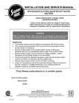
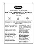
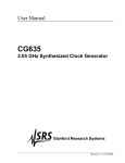
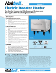
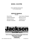
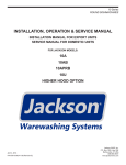
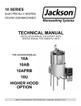
INSTALLATION AND SERVICE MANUAL
SPACESAVER ELECTRIC BOOSTER HOT WATER
HEATERS
MAKE DISHWASHING CLEANER, SAFER
AND MORE EFFICIENT
4 kW to 54 kW, 208 Vac to 600 Vac, Single or Three Phase
180ºF instantaneous hot water for commercial dishwashers
Suitable for installation with all “name-brand” dishwashers
WARNING
Risk of electric shock. This unit may be connected to more than one
electrical circuit. Disconnect all electrical circuits before servicing.
IMPORTANT
• The booster heater must be installed in accordance with all local codes.
• This manual must be left with owner and should be hung adjacent to the
booster heater for reference.
• Ensure booster heater is full of water before turning on electricity. Elements
will burn out immediately without water in the booster heater.
• Booster heater voltage must be correct for voltage available. Check
nameplate on the booster heater for full information.
• Overcurrent protection between the power supply and the booster heater
must be provided in accordance with the related code.
• Always ensure power switch is turned off before servicing.
• Under no circumstances should any electrical wiring or internal controls be
touched, except by a qualified electrician or any heating system be adjusted,
except by a qualified service technician.
Post these instructions in a visible place.
DATE OF INSTALLATION :
INSTALLED BY :
PHONE :
Manufactured by
Allied Engineering Company
Division of E-Z-Rect Manufacturing Ltd.
Manufacturers of Gas and Electric Boilers, Stainless Steel Tanks, Tankless Coils, Electric Boosters
94 Riverside Drive, North Vancouver, B.C. V7H 2M6 • Telephone (604) 929-1214 • FAX (604) 929-5184
Branches: Calgary • Edmonton • Toronto
PN5152451
(OPTIONAL)
PRICE $6
Electric Booster– Installation, Operating and Maintenance Instructions
Dimensions, Piping Diagram and Specifications
1.1
DIMENSIONS AND PIPING DIAGRAM
Figure 1 – Dimensions and Piping Diagram
1.2
TECHNICAL SPECIFICATIONS
Maximum Operating Pressure
Maximum Operating Water Temperature
Water Capacity in boiler – 4-18kW
Water Capacity in boiler – 24-54kW
Inlet and Outlet Pipe Size
CSA
130 p.s.i.
210ºF
4.27 US Gallons
5.80 US Gallons
3/4” NPT
2
Section 1
Electric Booster– Installation, Operating and Maintenance Instructions
Dimensions, Piping Diagram and Specifications
Section 1
TABLE 1. Super Hot Electric Booster Heater Specifications (Flange Type Elements)
BOOSTER MODEL NUMBERS, kW RATINGS AND MAX. AMPERAGE DRAW
Maximum Amperage Draw
Model
Number
kW
Btu/Hr
Tank
Capacity
U.S. Gal
U.S. Gal./Hr
40ºF Rise
304B
305B
306B
307B
309B
312B
313B
315B
318B
424B
427B
430B
436B
439B
545B
554B
4
5
6
7
9
12
13
15
18
24
27
30
36
39
45
54
13,649
17.062
20,474
23,884
30,711
40,948
44,356
51,185
61,422
81,895
92,124
102,369
122,843
133,068
153,554
184,264
4.27
4.27
4.27
4.27
4.27
4.27
4.27
4.27
4.27
5.80
5.80
5.80
5.80
5.80
5.80
5.80
41
52
62
72
93
124
135
156
187
249
280
311
373
405
467
560
208
240
208
240
480
600
Approx.
Shipping
Weight
19.2
24.0
28.8
33.7
43.3
57.7
62.5
72.1
86.5
115
130
144
173
188
216
260
16.7
20.8
25.0
29.2
37.5
50.0
54.2
62.5
75.0
100
113
125
150
163
188
225
--16.6
21.0*
25.0
33.3
37.6*
46.4*
54.6*
66.5
74.9
83.2
100
108
125
150
--14.4
18.2*
21.6
28.8
32.6*
40.2*
47.3*
57.7
64.9
72.1
86.5
93.7
108
130
--7.2
9.1*
10.8
14.4
16.3*
20.1*
23.7*
28.8
32.4
36.0
43.3
48.8*
54.1
64.9
--5.8
7.3*
8.7
11.5
13.0*
16.1*
18.9*
23.1
26.0
28.8
34.6
39.1*
43.3
51.9
60 LBS
60 LBS
60 LBS
60 LBS
60 LBS
65 LBS
65 LBS
65 LBS
70 LBS
70 LBS
70 LBS
75 LBS
75 LBS
80 LBS
90 LBS
90 LBS
Single Phase
Three Phase
SPECIFY MODEL NUMBER, VOLTAGE AND EITHER 1 OR 3 PHASE WHEN ORDERING
* Delta connection (unbalanced load) amperage of high leg indicated.
1.3
WATER TEMPERATURE RECOVERY
Booster Heater water recovery formulas:
415 x kW
G.P.H. (U.S.) =
Temp. Rise (ºF)
874 x kW
L.P.H. =
Temp. Rise (ºC)
TABLE 2. Water Temperature Recovery in GPH (LPH)
Model
kW
30ºF (17ºC)
40ºF (22ºC)
50ºF (28ºC)
60ºF (33ºC)
70ºF (39ºC)
80ºF (44ºC)
304B
4
55 (208)
41 (155)
33 (125)
28 (106)
24 (91)
21 (79)
18 (68)
305B
5
69 (261)
52 (197)
41 (155)
34 (129)
29 (110)
26 (98)
23 (87)
306B
6
83 (314)
62 (235)
50 (189)
41 (155)
35 (132)
31 (117)
27 (102)
307B
7
97 (367)
72 (272)
58 (219)
48 (181)
41 (155)
36 (136)
32 (121)
309B
9
124 (469)
93 (352)
75 (284)
62 (235)
53 (200)
47 (178)
41 (155)
312B
12
166 (628)
124 (469)
100 (379)
83 (314)
71 (269)
62 (235)
55 (208)
313B
13
180 (681)
135 (511)
108 (409)
90 (341)
77 (291)
67 (254)
60 (227)
315B
15
208 (787)
156 (590)
125 (473)
104 (394)
89 (337)
78 (295)
69 (261)
318B
18
249 (942)
187 (708)
149 (564)
125 (473)
107 (405)
93 (352)
83 (314)
424B
24
332 (1256)
249 (942)
199 (753)
166 (628)
142 (537)
125 (473)
111 (420)
427B
27
374 (1415)
280 (1060)
224 (848)
187 (708)
160 (606)
140 (530)
125 (473)
430B
30
415 (1571)
311 (1177)
249 (942)
207 (783)
178 (673)
156 (590)
138 (522)
436B
36
498 (1885)
373 (1412)
299 (1132)
249 (942)
213 (806)
187 (708)
166 (628)
439B
39
539 (2040)
405 (1533)
324 (1226)
270 (1022)
231 (874)
202 (765)
180 (681)
545B
45
622 (2354)
467 (1767)
373 (1412)
311 (1177)
267 (1010)
233 (882)
207 (783)
554B
54
747 (2827)
560 (2120)
448 (1695)
373 (1412)
320 (1211)
280 (1060)
249 (942)
3
90ºF (50ºC)
Electric Booster– Installation, Operating and Maintenance Instructions
Installation Instructions
2.1
Section 2
RECEIVING
INSPECT SHIPMENT FOR POSSIBLE DAMAGE. All goods are carefully manufactured, inspected,
checked and packed by experienced workers. The manufacturer's responsibility ceases upon delivery of
goods to the carrier in good condition. Any claims for damage, shortage in shipment or non-delivery must
be filed immediately against the carrier by the consignee.
2.2
INTRODUCTION
With a great reputation of quality and reliability, Super Hot booster heaters can produce 180ºF rinse water
making dishware cleaner, odorless and safer. Compared with other methods of sanitizing, the Super Hot
Electric Booster is the economical choice, having high efficiency and using less detergent and rinse
additives. Super Hot booster heaters provide the best sanitation method for your dishware dishwashing.
2.3
CAUTION
1. Disconnect all power supplies to prevent electrical shock and damage to equipment.
2. Installer must be a qualified, experienced service technician.
3. Conduct a thorough checkout when installation is complete.
2.4
BOOSTER HEATER LOCATION
The space saving compact booster heaters can be installed
almost anywhere. The booster heater may be installed in an
enclosed space and attached directly to a combustible
surface, however, allow ample space for connecting,
disconnecting and servicing the unit. Locate booster heater
as close to dishwasher as possible. Dimensions are shown in
Figure 1.
Sturdy plated steel legs are standard, but stainless steel
hanging brackets for under counter suspension are also
available (specify when ordering), see Figure 2.
2.5
PIPING
Figure 2 – Optional Hanging Brackets
The recommended piping arrangement is shown in Figure 1.
Use copper tubing only. Install the pressure reducing valve (preset for 20 psi). Install the temperature
and pressure relief valve on the booster heater and plumb discharge in accordance with local codes. The
temperature and pressure gauge attaches to a tee on the inlet between reducing valve and booster
heater. It is mandatory that a diatrol expansion chamber and shock absorber be installed in the line
between booster heater and dishwasher (as close to dishwasher as possible). In addition, it is
recommended that the inlet and outlet lines be insulated to prevent heat loss and that unions be used for
piping connections to ease service.
All Super Hot booster heaters have 3/4" NPT inlet and outlet pipe size. Dielectric couplings should be
used in connecting dissimilar metals, such as galvanized to copper, to prevent electrolysis. A check
valve should not be installed in the supply line to the booster heater. All shut-off valves must be gate or
ball valves, not globe valves.
2.6
FUNCTION OF PIPING ACCESSORIES
Expansion Chamber:
Quick closing solenoid valves on the dishwasher will produce a shock pressure exceedingly high – up to
800 lbs. This may cause leaks in the plumbing and damage equipment such as relief valves, gauges,
tank, and etc. To extend the life of the booster heater and other equipment, we recommend that a Diatrol
be installed on all installations.
4
Electric Booster– Installation, Operating and Maintenance Instructions
Installation Instructions
Section 2
Temperature and Pressure Indicating Gauge:
This gauge indicates the temperature and pressure and is useful when determining incoming water
temperature or adjusting the pressure reducing valve. It should be installed between the pressure
reducing valve and booster heater.
When a dishwasher is not equipped with a temperature gauge, a second gauge should be installed as
close to dishwasher as possible to verify 180ºF rinse temperature.
Temperature and Pressure Relief Valve:
The relief valve protects the tank from becoming overheated and/or over-pressurized. It opens and
releases water if the temperature exceeds 210ºF or if the pressure exceeds 125 psi (satisfies most local
codes). This device must be installed directly on the booster heater.
Pressure Reducing Valve with By-Pass:
When the supply pressure exceeds the final rinse pressure requirements, a pressure reducing valve with
built-in by-pass should be installed in the supply line to the booster heater. A pressure reducing valve
without a by-pass should not be installed, as water expansion due to heating will cause the relief valve to
open.
Optional Extra Low Water Cut-Off:
A number of service calls are caused by energizing the heating elements in a “dry” tank. Even
momentary testing of the installation when the tank is dry will appreciably shorten the life of the element
or burn it out and affect the calibration of the aquastat.
The low water cut-off will protect from burnout of heating elements by checking that the tank is completely
filled with water before allowing the elements to operate.
5
Electric Booster– Installation, Operating and Maintenance Instructions
Wiring and controls Instructions
3.1
Section 3
WIRING
CAUTION:
AC ONLY, USE COPPER WIRE ONLY, DO NOT USE ALUMINUM.
All electrical wiring is to be done in accordance with the Canadian Electrical Code, CSA C22.2 part 1,
and/or any local regulations and codes in Canada, or the National Electrical Code, ANSI/NFPA 70 (latest
edition) and/or any local regulations and codes in U.S.A. Verify the nameplate rating and check the
related codes to properly size conductors, switches and over-current protection. Check the voltage at the
feeder panel, compare to the values shown in Table 1, and supply the correct voltage power to the power
supply block on the booster heater. For wire connections, refer to the wiring diagram sticker on the back
of the booster heater front cover.
3.2
CONTROLS
A custom designed “rapid response” aquastat provides temperature control ensures safe operation. The
aquastat switch incorporates a magnetic contactor to complete the power circuit to the heating elements
and control the water temperature. By use of an adjustable dial the operating aquastat can control the
water to the desired temperature.
The electrical controls come pre-wired on the right-hand side of each booster heater where it is protected
from high ambient temperatures.
An indicator light visible on the front panel indicates that there is power to the heating elements when the
booster heater is in operation.
The low water cut-off (optional) uses a resistance-sensing probe to determine if the booster heater is
filled with water. If the booster heater is filled with water, the relay coil will close and allow the element to
turn on. Sensing resistance is dial-adjustable, turn dial clockwise to increase sensitivity.
6
Electric Booster– Installation, Operating and Maintenance Instructions
Start-up Instructions
4.1
Section 4
START-UP
WARNING:
The following instructions are intended as a guide for qualified persons. Before
switching power on, fill system with water and vent air. Check for and repair any leaks in
water piping.
Perform the following procedure to check for proper booster heater operation:
1. Set operating aquastat to give desired water temperature for dishwasher (usually 180ºF).
2. The operating aquastat setting should be at least 20ºF less than the temperature relief setting
(210ºF).
3. Lift relief valve handle to ensure the booster heater is completely filled with water.
4. Check flow pressure with water flowing through the booster heater and, if necessary, readjust the
pressure reducing valve to 20 psi or to pressure recommended by dishwasher manufacturer.
5. The pilot lamp indicates that power is on when booster heater is operating.
Maintenance Instructions
5.1
Section 5
IMPORTANT
Many times when a booster heater does not appear to be functioning properly, the fault lies not with the
booster heater itself but with factors outside of the heater. Therefore, before becoming involved in
corrective work on the booster heater, the following steps should be followed:
Check the temperature of the water feeding into the booster heater tank. It must be 140ºF or the
temperature designed and must be in sufficient quantity to hold its temperature throughout the
dishwashing operation.
Incoming water temperature to the booster heater should not exceed 170ºF.
If incoming water exceeds 20 psi, a pressure reducing valve must be installed.
If the wash tank of the dishwasher is filled through the booster heater, this will use up all the
180ºF water in storage. Sufficient time must be allowed to reheat the water in storage before
starting the dishwasher.
Water pressure at the inlet to the booster heater must be adequate for proper operation of the
rinse cycle of the dishwasher.
Be sure that the relief valve is one supplied by Allied Engineering Company.
A check valve should not be installed ahead of the booster heater. Remove if present.
7
Electric Booster– Installation, Operating and Maintenance Instructions
Booster Heater Size for Dishwasher Installations
Section 6
6.1 BOOSTER HEATER SIZING CHART
All sizing are based on dishwasher manufacturer ratings. Confirm the booster size with dishwasher
manufacturer before ordering it. Allied Engineering Company is not responsible for incorrect sizing of
applications.
TABLE 3. Super Hot Booster Heater Sizing for Dishwashers
BOOSTER HEATER SIZING CHART
CSL-1390, CA-2, CA-3, CA-4
CA, CA-1
UC-21
D-8
Series “R” & “F”-CC, -EE, -LL, -MM, -LLL, -MMM, -PCC, -PEE,
-PLL, -PMM (Multi-tank) with suffix “LC”
Series XF-LL, XF-PLL, XF-MM, XF-PMM, XF-EEE, XF-LLL, XF-MMM
(Multi-tank) with suffix “LC”
DD-8
Series R-L, R-PL, R-M, R-PM, F-L, F-PL, F-M, F-PM (single-tank)
Series XF-L, XF-PL, XF-M, XF-PM (single tank)
Series XF-PEE, XF-PLL, XF-PMM, XF-EEE, XF-LLL, XF-MMM (Multi-tank)
FA (Flight-A-Round) and RA (Rack-A-Round) use comparable “F” listing.
UH1
DH1, DH1C
44WS, 66WS
PP28
40KB, 44KB, 54KB, 60KB, 64KB
UC-C
UC-CW (6 ft center max)
CHEMICAL
METHODS
ASSOC.
HOBART
DISHWASHERS
ADAMATION
BLAKESLEE
CHAMPION
40ºF RISE
439B
554B
306B
309B
70ºF RISE
(2) 436B
(2) 545B
312B
313B
313B
424B
317B
430B
318B
436B
(2) 436B
545B
430B
554B
--(2) 430B
306B
309B
315B
427B
436B
545B
554B
309B
318B
427B
545B
554B
(2) 436B
(2) 439B
CMA-44H with tank heater
424B
545B
LX-30
LX-18C, XL-30C, LX-40C, UM-4D, UMP-4D, WM-1D, WMP-1D, WM-5
LX-18
WM-5C
SM-6T2
WM-5
AM-14T, AM-14F, AM-14TC
UM-4, UMP-4, WM-1, WMP-1
AM-12, AM-12C, AM-14, AM-14C
C-44AW, CRS-66AW, CPW-80AW
C-64W, CRS-86W, CPW-100W, C-88W, CRS-110W, CPW-124W
FT800W
C-64A, CRS-86A, CPW-100A, CMT-44
C-44, CRS-66, CPW-80, C-44A, CRS-66A, CPW-80A, C-88A, CRS-110A,
CPW-124A
C-64, CRS-86, CPW-100
FT-600, FT-700, C-54, CRS-76, CPW-90
FT-300
FT800
FT800S, CRS-76A, CPW-90A, C-54A
UTW-28, UTW-28C
304B
304B
305B
306B
306B
307B
309B
309B
309B
312B
424B
424B
430B
307B
307B
309B
309B
312B
312B
313B
315B
312B
424B
436B
439B
554B
436B
554B
545B
554B
554B
439B
439B
318B
(2) 436B
(2) 439B
(2) 545B
554B
(2) 436B
436B
8
Electric Booster– Installation, Operating and Maintenance Instructions
Booster Heater Size for Dishwasher Instructions
Section 6
BOOSTER HEATER SIZING CHART
Commander 18-3, 18-4, 18-4h, Ensign 40-2
Trac 321, Trac 321-2/RPW
Admiral 44-4, 66-4
Acmiral 44, 66-3
Speeder 7, 64, 86-3, Century 14
Master (all)
Clipper (all)
R106-2, Super 106-2
Defender
JP-24, JP-24B, JP-24F, JP-24BF
24B Series
10AB, 10APRB
44CE*, 66 CERPW
54CE, 76 CERPW
64CE, 86 CERPW
100
100B, 100PRB, 150B, 150PRB
150
200
200B
Tempstar, Tempstar SDS
AJ-44, AJ-66, AJ-80
AJ-54, AJ-76, AJ-90
AJ-64, AJ-86, AJ-100
*Model #44CE w/SN1999 or below requires larger booster than listed.
40ºF RISE
306B
318B
424B
424B
424B
436B
424B
427B
436B
304B
----430B
436B
427B
312B
--312B
307B
--306B
424B
436B
424B
70ºF RISE
312B
430B
436B
439B
545B
554B
545B
545B
554B
306B
304B
305B
554B
(2) 430B
439B
424B
309B
318B
312B
306B
312B
545B
(2) 430B
439B
KNIGHT
EQUIPMENT
(CANADA) LTD.
KLE-112-HL
307B
312B
METALWASH/
INTEDGE
FW4
312B
318B
SF-1RA, SC20-1
SF-2RA, SF-2DRA, SD-2RA, SDRA, SDRA-PACK
SCT-44, SCT-44-10, SCT-54, SCT-76S, SCT-76SC, SCT-76SM
SCT-64, SCT-76, SCT-80, SCT-94, SCT-108, SCT-120, SCT-94S,
SCT-108S, SCT-120S, SCT-94SC, SCT-108SC, SCT-120SC, SCT-94SM,
SCT-120SM, SCT-150SM
U-31-A
U-31-A2, STPCW-5, STPCW-19, STPCW-19PS, STPCW-20, STPCW-22,
STPCW-24
STPCW-12PS, STPC-15S
STPC-12PS, STPC-15S
STPC-15, STPC-19, STPC-19S, STPC-20, STPC-22, STPC-24
STBUW-14
SC-2-4, SC-6-4, SC-1-2-3, SC-1-6-4, SC-5-6-4, SC-5-2-4
SC-2-3-4, SC-6-3-4, SC-2-7-4, SC-1-2-7-4, SC-1-6-3-4, SC-5-2-3-4,
SC-1-6-7-4, SC-5-6-3-4, SC-5-2-7-4
SC20-2
SC-2-8, SC-2-9, SC-1-2-8, SC-5-6-8, SC-6-8, SC-6-9, SC-1-6-8, SC-5-6-9,
SC-5-2-9, SC-1-6-9, SC-5-2-8
R16BTF, CU16BTF
3D20TF, CD20TF
A-64 Series, A-81 Series
A44 Series, A54 Series, CP-2, CP-3, HP-3
307B
312B
436B
312B
318B
554B
545B
554B
436B
554B
545B
(2) 436B
554B
554B
436B
554B
436B
(2) 554B
(2) 439B
(2) 430B
(2) 554B
545B
430B
(2) 427B
312B
424B
318B
436B
309B
312B
430B
545B
318B
424B
554B
(2) 439B
DISHWASHERS
INSINGER
JACKSON
STERO
VULCAN-HART
9
Electric Booster– Installation, Operating and Maintenance Instructions
General Information
7.1
Section 7
REPLACEMENT PARTS
Figure 3 – Replacement Parts
7.2
ORDERING
A replacement or replacement parts may be purchased through any Allied Engineering Company
distributor – call us to help locate a distributor near your area. If you require any technical assistance or
have any comments about our product, please write or phone us.
Service Department
Allied Engineering Company
94 Riverside Drive
North Vancouver, B.C. V7H 2M6
Telephone: (604) 929-1214
Fax: (604) 929-5184
10
Electric Booster– Installation, Operating and Maintenance Instructions
Trouble Shooting
8.1
Section 8
TROUBLE SHOOTING
Problem
Possible Cause
Solution
Temperature too low or too
high. (Read rinse thermometer
on dishwasher).
Incorrect thermostat setting.
Remove booster heater front panel.
Adjust thermostat to correct setting
and check thermometer during rinse
cycle.
If machine cold, run rinse cycle twice
before checking proper reading.
Temperature should reach 180ºF –
185ºF (82ºC –85ºC).
Rinse water temperature still
too low during continuous use.
Thermostat fault.
Check and replace, if necessary.
Water supply to booster
heater below 140ºF (60ºC).
Read incoming water temperature by
combination gauge.
Incoming
temperature should be 140ºF (60ºC)
(unless booster heater is specifically
designed
for
lower
supply
temperature).
Increase incoming water temperature
to 140ºF (60ºC) at hot water supply
tank.
Pressure setting of pressure
reducing valve too high.
Read pressure on combination gauge
during rinse cycle.
Pressure reducing valve “PRV”
should be adjusted to dishwasher
specifications usually between 20 –
25 p.s.i.
Thermometer on dishwasher
not functioning properly.
Tap thermometer gauge with finger
during rinse cycle. If needle does not
move freely, contact dishwasher
manufacturer.
Booster heater too far from
dishwasher (more than 3 ft.)
Insulate pipe from booster heater to
dishwasher.
Relocate booster heater closer to
dishwasher.
Heating element(s) burned
out, faulty contactor or loose
wires
11
Turn off electricity to the booster
heater. Check elements, contactor
and wiring for continuity.
Electric Booster– Installation, Operating and Maintenance Instructions
Trouble Shooting
Section 8
Problem
Pressure temperature
valve discharges water
relief
Possible Cause
Solution
Thermostat set too high
above 185ºF (85ºC)
Remove front cover. Adjust thermostat
to a lower setting.
Pressure increases to 125
p.s.i. during booster heater
heating cycle because:
A. Pressure
reducing
valve is an incorrect
style (without relief bypass).
Letter “B”
should be in model
number.
Replace with correct pressure reducing
valve.
B. By-pass in pressure
reducing valve plugged
or inoperative.
While unit in heating cycle, tap
pressure-reducing valve with wood
hammer or screwdriver handle.
If
pressure gauge does not show drop in
pressure, replace pressure-reducing
valve.
Pressure temperature relief
valve discharges water (after
checking above).
Relief valve not reseating
properly.
Quickly lift and release manual
discharge lever on relief valve to assist
proper reseating. If this fails, replace
temperature and pressure relief valve.
Water leaking from booster
heater.
Element and thermostat
threads may be leaking.
Turn off electricity to booster heater and
tighten elements.
Turn off water, drain, remove and apply
sealant if necessary. (Be sure to turn
off electricity before draining or
elements will burn out).
Plumbing connections may
be leaking.
12
Tighten incoming pipes, heating
elements,
and
temperature
and
pressure relief valve. Turn off water,
drain and remove and apply sealant if
necessary.
(Be sure to turn off
electricity before draining or elements
will burn out).
Electric Booster– Installation, Operating and Maintenance Instructions
Notes
Section 9
13
Electric Booster– Installation, Operating and Maintenance Instructions
Index
10.0
Section 10
INDEX
Section Description .................................................................................................................................Page
1.0
1.1
1.2
1.3
Dimensions, Piping Diagram and Specifications
Dimensions and Piping Diagram ..................................................................................................... 2
Technical Specifications .................................................................................................................. 2
Water Temperature Recovery.......................................................................................................... 3
2.0
2.1
2.2
2.3
2.4
2.5
2.6
Installation Instructions
Receiving ......................................................................................................................................... 4
Introduction ...................................................................................................................................... 4
Caution............................................................................................................................................. 4
Booster Heater Location .................................................................................................................. 4
Piping ............................................................................................................................................... 4
Function of Piping Accessories........................................................................................................ 4
3.0
3.1
3.2
Wiring and Control Instructions
Wiring ............................................................................................................................................... 6
Controls............................................................................................................................................ 6
4.0
4.1
Start-up Instructions
Start-up ............................................................................................................................................ 7
5.0
5.1
Maintenance
Important .......................................................................................................................................... 7
6.0
6.1
Booster Heater Size for Dishwasher Installations
Booster Heater Sizing Chart ............................................................................................................ 8
7.0
7.1
7.2
General Information
Replacement Parts ........................................................................................................................ 10
Ordering ......................................................................................................................................... 10
8.0
8.1
Trouble Shooting
Trouble Shooting............................................................................................................................ 11
9.0
Notes ............................................................................................................................................. 13
10.0
Index .............................................................................................................................................. 14
14