1
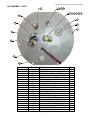
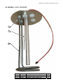
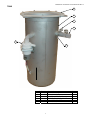
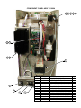
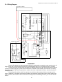
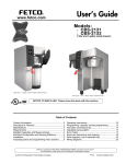
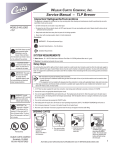
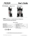
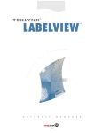
Manual PN 119985 Rev 02-06
20:1 Brewer Operation and Service Manual
Model
Height
Width
Depth
US 120 V
NB-LD
NB-TD
17-7/8
24-3/16
8-1/2
8-1/2
19-1/4
19-1/4
14.6A
14.6A
1
Canada 120
V
11.7A
11.7A
240 V
14.6A
14.6A
Manual PN 119985 Rev 02-06 Firmware Rev 4
20:1 INSTALLATION / SETUP INSTRUCTIONS
WARNING: - Read and follow installation / setup instructions before plugging or wiring in machine to electrical
circuit. Warranty will be void if machine is connected to any voltage other than that specified on the name plate.
Plumber's Installation Instructions
1) Plumb brewer in to water supply using 1/4 inch copper tubing. Flush water line before installing brewer to remove
sediment. Brewer should be connected to COLD WATER LINE for best operation.
2) Water pressure should be at least 20 lbs. For less than a 25 ft run, use 1/4" tubing and connect to 1/2" or larger
water line. The inlet water fitting on the back of the brewer is a 1/4" flare fitting.
3) If installed with saddle valve, the valve should have a minimum of 1/8" port hole for up to 25 ft run, and 5/16" port
hole for over 25 ft runs.
4) Check for leaks.
Initial Setup Instructions
Ensure power switch on right rear of unit is in the off position. Plug or wire brewer to the appropriate voltage circuit as
indicated on the serial tag. Turn power switch to the on position. Brewer tank will begin to fill. Once the tank is full
the brewer will begin to heat. Ready light will come on to indicate tank has finished heating.
CAUTION: The water faucet will dispense hot water anytime the handle is pulled.
Programming
The brewer has two program modes, service mode and user mode. The service mode is used to establish basic
operating parameters of the unit while the user mode allows the three buttons to be programmed for brewing into
various containers or for varying beverage volumes. Programming mode is initiated as outlined below. The following
will outline the various steps as displayed by the programming “screens”. The screens will loop continuously until
exiting the mode.
Service Mode is entered by holding any two of the buttons on the face of the machine while powering up the brewer.
The brewer firmware revision number is displayed for a couple of seconds when entering this mode. The table below
list the items that may be programmed along with available values or settings. Use the center brew button to advance
through the items and the left and right button to decrement or increment the values/selection respectively. These
items are programmed at the factory and will typically not need adjustment.
Item Selected
Screen
Example
200
On
Values
Available
170-205
On, OFF
Brew Pump Speed
Not Used
Pump Calibration
Volume Delivered
During Calibration Step
Water Fill Flow Rate
b:05
F:05
CAL
39.0
1-10
1-10
N/A
16.0-99.9
0.30
Off, 0.20-1.40
Water Filter Capacity
Power Mode
Power Down/Save
Time
Brew Counter
Service Data
100
nor
4:00
Off, 500-2000
nor, SAV, dn
0:30-4:00
0-999
Srv
N/A
N/A
End
N/A
Water Temperature
End of Cycle Beeper
Exit
Comment
Degrees F
Used to audibly indicate brew cycle has completed with a
series of beeps.
Pump speed used for brewing
No effect. Unused feature.
See instructions below. Must be done if pump speed modified.
Ounces. Only displays if calibration cycle was run.
Adjustable in increments of .05 GPM. Should match flow rate
through valve.
In tens of gallons. 50=500 gallons. Increments are 500 gallons.
Normal, Power Down, or Power Save.
Hours:Minutes from last brew until brewer enters the selected
power mode. No effect if mode is “Off”.
Shows number of brew cycles since last reset (up to 999).
Used to view temperature & probe data. See Service Data
below.
Use left or right button when displayed to exit this mode.
2
Manual PN 119985 Rev 02-06 Firmware Rev 4
Pump calibration is necessary when the pump speed is changed or if the brewer is delivering substantially more or
less beverage than what it has been programmed for in the user mode. Pump speed may be adjusted up or down if
required to deliver water at a faster or slower rate to meet a specific beverage taste profile. Calibration tells the
brewer control how much hot water is delivered within a specific time frame so it can adjust the time required to run to
deliver the desired brew volumes.
Ensure the brew basket is in place. Place a suitably graduated container in place below the brew basket to capture
and measure the water delivered. To calibrate, enter the service mode as noted above and advance to the “CAL”
screen. Press either the left or right brew button and water delivery will begin. If the brewer has not reached
operating temperature, it will finish heating before automatically starting. The pump will cycle on and off for
approximately 2 minutes at which time the currently programmed volume is displayed. Use the left and right button to
decrement or increment the value to the measured value. For better accuracy, you may want to measure a couple of
cycles and average the measured values. Note that user mode will be entered automatically when exiting the service
mode if calibration values have been changed.
Service Data consist of the tank temperature as measured at two points in the tank and an indication as to which
probe(s) are making contact with the water. To view data, enter the service mode as noted above and advance to
the “Srv” screen. Use the left or right button to enter service data mode. Use the center button to advance through
the data. The table below list the data that is displayed.
Data displayed
Screen
Example
198
.
20 0
1:UL
End
Lower Temperature
Upper Temperature
Probes
Exit
Values
Available
N/A
N/A
U,L,UL
N/A
Comment
Degrees F
Degrees F
Displays probes in contact with the water; Upper, Lower or Both.
Use left or right button when displayed to exit this mode.
User Mode is entered by holding any of the buttons on the face of the machine while powering up the brewer. Note
that the user mode is also automatically entered whenever the calibration volume setting is changed. The beverage
volume, brew time, and visa-brew time can be programmed for each of the three buttons on the face of the brewer.
The brewer will determine the minimum brew time possible based on pump speed and calibration values as outlined
previously. This time is set as the default whenever calibration values are changed. The brew time can be extended
to lengthen the water delivery time to meet a specific beverage taste profile. The table below list the data displayed
and values available.
Data displayed
Brew 1 Settings
Screen
Example
b1
Values
Available
N/A
Brew 1 Volume
Brew 1 Time
Visa-brew 1 Time
64
3:30
0:30
Off, 30-128
Min-9:59
0:00-4:00
Brew 2 Settings
b2
N/A
Brew 2 Volume
Brew 2 Time
Visa-brew 2 Time
64
3:30
0:30
Off, 30-128
Min-9:59
0:00-4:00
Brew 3 Settings
b1
N/A
Brew 3 Volume
Brew 3 Time
Visa-brew 3 Time
64
3:30
0:30
Off, 30-128
Min-9:59
0:00-4:00
Exit
End
N/A
Comment
Displays briefly to indicate that the parameters are for brew
button 1 (left)
Ounces. Button can be turned off and will serve as cancel only.
Calculated minimum to 9 minutes and 59 seconds.
Set to allow for beverage to finish dripping from basket after
water delivery time has been completed.
Displays briefly to indicate that the parameters are for brew
button 2 (center)
Ounces. Button can be turned off and will serve as cancel only.
Calculated minimum to 9 minutes and 59 seconds.
Set to allow for beverage to finish dripping from basket after
water delivery time has been completed.
Displays briefly to indicate that the parameters are for brew
button 3 (right)
Ounces. Button can be turned off and will serve as cancel only.
Calculated minimum to 9 minutes and 59 seconds.
Set to allow for beverage to finish dripping from basket after
water delivery time has been completed.
Use left or right button when displayed to exit this mode.
3
Manual PN 119985 Rev 02-06 Firmware Rev 4
OPERATION INSTRUCTIONS
Coffee Preparation Procedures
1)
2)
3)
4)
5)
6)
7)
8)
9)
10)
Place filter into brew basket.
Put the proper amount of coffee into the filter.
Slide the brew basket into holder.
Place the appropriate empty decanter into position below the brew basket. For airpots first open lid and remove
pump stem unless of a brew through design. For other dispensers remove the lid unless it is a brew through
design.
Press the appropriate brew start switch. Note: a brew cycle may be initiated even if the heating light is on. The
brewer features an autoarm circuit which will flash the heating light indicating that the brewer is heating and will
begin to brew immediately after the heating cycle is complete. To over ride autoarm, hold in brew button until
cycle starts (5 seconds).
Do not remove decanter. Brew cycle may be canceled by depressing any brew button or the cancel switch on
the front control panel.
Hot water will be delivered through the sprayhead. This distributes the hot water evenly over the coffee bed
within the brew basket. The coffee brew will drain from the brew basket into the decanter below.
The Brewing light should continue to flash until all the liquid has finished flowing from the brew basket. Do not
remove decanter until the brewing process has stopped and all liquid has stopped flowing from the brewbasket.
The resultant coffee brew should be crystal clear and have the desired properties attainable through excellent
extraction.
To clean brew basket simply remove from brew rails and dump filter into waste basket. The brewing process, as
described above, can now be started again.
Error Messages
This brewer incorporates a number of self diagnostic test that are routinely run. If a fault condition should occur the
unit will display an error number as outlined below. All errors may be reset by powering unit off and then back on.
Errors E1 and E2 are auto-resttable and will clear themselves if the condition that caused them goes away. You may
still brew, but call for service. E3 will disable heater but will allow brewing to take place. E4 and E-A must have power
to unit cycled to clear them. E5 will force brewer to use its default settings for brewing. E7 and E8 will clear when a
brew cycle is started. E9 will disable input from dsplay board. If error repeats, correct the cause of the error.
Error
Number
E1
Cause
What to Check
Resistance extremely high from
upper or lower thermistor
Resistance extremely low from upper
or lower thermistor
Water did not heat within timeout
period
Water did not reach probe in timeout
period
Check/replace thermistor.
E4
Open
Thermistor
Shorted
Thermistor
Heater Run
Error
Tank Fill Error
E5
Comm Error
E7
Open Motor
Circuit
Bad (Open)
Motor Driver
SPI Comm Error
Serial communication error to/from
non-volatile memory (EEPROM).
Open motor circuit. Pump 0 or
pump 1.
Bad/open motor driver. Pump 0 or
pump 1.
Serial communication error to/from
display board.
Water system may have a leak.
E2
E3
E8
E9
E-A
Full
Description
Possible Leak
Detected
Filter Full
Water filter has reached capacity.
4
Check/replace thermistor.
Check element for short and proper
resistance. Replace if bad.
Check valve function and flow rate.
Replace valve or increase flow rate. Check
probes for excess scale.
Replace main board.
Check harness/motor continuity. Replace
if defective.
Replace main board.
Verify good connection in proper port. Try
new display board. Try new main board.
Check all plumbing system components for
possible leak. Look for water on counter.
Replace filter.
Manual PN 119985 Rev 02-06 Firmware Rev 4
LID ASSEMBLY 119972
2
1
3
4
5
6
7
8
19
11
18
12
13
17
16
15
14
Item #
1
2
3
4
5
5 Alternate
6
6 Alternate
7
8
9
10
11
12
13
14
15
16
17
18
19
Part #
100190
119997
119991
100030
100149
100177
100445
119836
202044
110946
110944
101720
102836
119891
119973
152207
151677
152198
100269
111593
202025
Description
NUT, 1/2 –20 JAM, BRASS
CONNECT, FM 3/8C x 1/8P, MOD
FITTING, 1/8 PIPE x 1/4 BARB
GASKET, BRS, .566 ID, TIN/PLTD
ELBOW, MALE, 1/4 COMP x 1/8
ELBOW, MALE, ¼ FLARE X 1/8 NPT
TUBING, TEFLON, 3/16 ID
COPPER TUBE ASSEMBLY
INSERT TUBING, 3/16
NUT, 1/4 SELF ALIGN
SLEEVE, 1/4 SELF ALIGN
CONNECT, FM 3/8C x 1/8P, TNPL
GROMMET, SIL, NO SLIT
PROBE SPTWLD
LID, TANK, PUNCHED, NB
PLUG, TANK CVR NATURAL SIL
PROBE, TEMP, DUAL, 7.312, THERM
14GA, VIO/BLK, 4 TEF, 1S-1S
BRACKET, HIGH LIMIT THERMO
THERMO, MAN/RESET
ELEMENT, TANK, 1750W, 120V
5
Qty
2
1
1
2
1
1
1
1
1
1
1
3
2
1
1
1
1
1
1
1
9 10
Manual PN 119985 Rev 02-06 Firmware Rev 4
LID ASSEMBLY 119972, CONTINUED
1
2
3
Item #
1
2
3
Part #
100409
151677
202025
Description
GASKET, BRASS, .520ID, TN/PLT
PROBE, TEMP, DUAL, 7,312 THERM
ELEMENT, TANK, 1750W, 120V
6
Qty
2
1
1
Manual PN 119985 Rev 02-06 Firmware Rev 4
TANK
1
2
3
4
6
5
Item #
1
2
3
4
5
6
Part #
704221
119971
111635
152213
102835
781772
7
Description
GASKET
TANK, PUNCHED
CLAMP, HOSE .574 ID
TUBING, SIL, 3/8 ID x 5/8 OD
BULKHEAD, FAUCET
PUMP, ASSY, WATER
Qty
1
1
2
2
1
Manual PN 119985 Rev 02-06 Firmware Rev 4
BREW PLATE / DISPLAY BOARD
1
2
3
4
5
~
6
8
9
Item #
1
2
Part #
100731
120025
Description
DISPLAY BOARD & HARNESS
SPACER, 6-32, 3/8 HEX x 7/16L
3
120046
SCREW, 6-32 x 1/4, PPHMS, POLY
3
4
110941
WASHER, NYL, .151 x .345 x .031
3
5
119970
BREW PLATE SPTWLD
1
6
7
8
9
152218
152213
111635
111597
TUBING, SIL, 1/4 ID x 3/8 OD
TUBING, SIL, 3/8 ID x 5/8 OD
CLAMP, HOSE, .574 ID
TUBE, SPRAYHEAD
2
1
8
Qty
1
3
7
Manual PN 119985 Rev 02-06 Firmware Rev 4
COMPONENT, PANEL ASSY - 119994
1
2
3
4
14 13
12 11
6
10
9
8
7
Item #
1
2
3
4
5
6
7
8
9
10
11
12
13
14
Part #
100255
110944
110946
202044
101527
105115
100022
101035
101898
110626
121659
110367-10
100729
102844
9
Description
KIP VALVE, SOLENOID
SLEEVE, 1/4 SELF ALIGN
NUT 1/4 SELF ALIGN
INSERT TUBING, 3/16
REPLACEMENT KIT, KIP VALVE
TRANSFORMER
CORD, POWER
GROMMET, STRN RELIEF
CORD PLATE
SWITCH, DP/ST, RECT, ROCKER
HEATSINK
RELAY, 50 AMP, SOLID STATE
MAIN BOARD
SUPPORT, CIRCUIT BOARD 3/8
Qty
1
1
1
1
1
1
1
1
1
1
1
1
1
4
5
Manual PN 119985 Rev 02-06 Firmware Rev 4
20:1 Wiring Diagram
SWITCH/DISPLAY BOARD
100731-2
TANK ASSEMBLY
VL/BK
RD RD
PROBE
SIGNAL IN
ON
YL
BK
RIBBON CABLE
TANK
HEATER
ELEMENT
BN
RD
BL
STANDARD
PROBE
VL/BK
RO
PROBE
VL/WH
THERMISTOR
ASSEMBLY
2 1
2 1
HI-LIMIT
THERMOSTAT
VL/BK
COMPONENT
PANEL ASSEMBLY
-
BK
+
RD
6 1
7 2
BK 8 3
BN 9 4
10 5
MAIN
CONTROL
BOARD
HEATER
RELAY
CN1
100729-2
BK\
WH
CN2
ON
4 1
5 2
6 3
BK
RD
RD
BK\
WH
BN
YL
RIBBON CABLE
CN3
OPTIONAL 240V WIRING
VL/WH
VL/BK
BK
WH
TANK
HEATER
ELEMENT
HEATER
RELAY
3 1
4 2
GY
BK
2
1
DP-A
CN5
BK
WH
PROG
SWITCH
DP-B
PROG
SWITCH
VL/WH
VL/BK
RD
BK
BK
RD
BK
WH
GY
BK\ BN BK\
WH
WH
GN
TRANSFORMER
POWER
CORD
WH
FILL
VALVE
WH
VL\BK
BK
L1
N
L2
WH
TERMINAL
BLOCK.
OPTIONAL
FOR 120 V
POWER
CORD
WARRANTY
Newco coffee brewers are warranted against defects in workmanship or materials, under normal use, for 90
days from the date of purchase. Brewer parts are warranted against defect for 12 months from date of purchase.
Liability in all events is limited to the purchase price paid and liability under the aforesaid warranty is limited to
replacing or repairing any part or parts which are defective in material or workmanship, and returned to our factory,
shipping cost prepaid. No warranty expressed or implied, other than the aforesaid is made or authorized by Newco
Enterprises, Inc.
Prompt disposition will be made if item proves to be defective, within warranty. Before returning any item,
write or call Newco, or the dealer from whom the product was purchased, giving model number, serial number, and
date of purchase, and describe nature of the defect. If damage was incurred during transit to you, file claim with the
carrier.
10