1
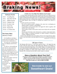
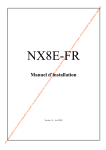
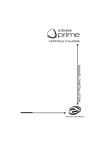
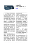
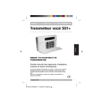
Product Review Column from QST Magazine
May 1997
ICOM IC-756 MF/HF/VHF Transceiver
Japan Radio Co. NRD-535D HF Receiver
Copyright © 1997 by the American Radio Relay League Inc. All rights reserved.
Product Review
Edited by Rick Lindquist, N1RL• Senior Assistant Technical Editor
ICOM IC-756 MF/HF/VHF Transceiver
By Glenn Swanson, KB1GW
Educational Programs Coordinator
“Honey, they shrunk the IC-781!” is
what some ops will exclaim when they see
the IC-756. It’s an easy comparison, and
one ICOM ad even calls it a radio “for the
ham who’s always wanted an IC-781.”
Features like the prominent front-panel LCD
display screen on the ’756 certainly hearken
back to its elder sibling, the IC-781, with its
conspicuous CRT display. As in the IC781, the IC-756 offers such features as
dualwatch and Spectrum Scope. But in
several respects, this is a different radio—
maybe better when you consider its price
and performance, the inclusion of DSP, and
an intuitive menu system.
At least a few reviewers were surprised
to find a package closer in dimensions to the
IC-736, the radio it replaces in ICOM’s
product line. But the IC-756 capitalizes
on—and even improves on—some of the
best features of its predecessors, and does
so with style. Let’s face it: that LCD screen
is just plain sexy! The easily accessible
menus, spectrum scope and the inclusion of
6 meters are icing on the cake.
In the greater scheme of things, the
IC-756 is a notch down from higher-end
offerings in terms of price, but competes
admirably with the big boys in several performance spheres. In terms of DSPequipped radios, the ’756 is intended for
more mainstream users.
During the review, we encountered some
transmitter-related problems that ICOM has
agreed to correct in future production units.
We’ll discuss these issues later in the review.
Feature Highlights
The first thing you need to do with the
IC-756 is to get past the LCD display window. Otherwise, you could overlook the
radio’s other assets. These include such
niceties as an automatic antenna tuner
(works on 6 meters!), dualwatch, dual antenna ports, a receive antenna port (for a
Beverage, EWE or other antenna), memory
keyer, front-panel adjustable CW pitch
control and tracking sidetone, triple bandstacking registers, twin passband tuning at
the 9-MHz IF, and more. A lot of these are
features traditionally included on ICOM’s
higher-priced radios, so it was great to find
them on the more modestly priced IC-756.
You’ll also find a generous array of memories and scanning features: 99 memories,
plus 2 priority memories; alphanumeric
memory naming (up to 10 characters); 5 or
10 memo pads; and four types of scanning.
The IC-756 lets you view the contents of
nine memory channels at a time (or scroll
through them all) via its memory channel
screen.
Standard accessories include a handmike with UP and DN buttons, a 9 1 /2 -footlong fused dc power cord, spare fuses, a
1
/ 4-inch stereo-type phone jack, and large,
detailed block and schematic diagrams.
The Screen
The LCD screen commands the blackplastic face of the ’756. (One user compared it to the screen on the ATM at her
bank!) The screen appears dark when the
radio is off, but illuminates when you turn
the radio on to reveal a light-blue background with dark-blue text, numerals and
graphics. A thin (unlighted) black mask
frames the screen, and a clear plastic lens
protects the flat LCD screen behind it. The
screen’s illuminated area measures approximately four inches wide by three
inches high—about the same size as the
IC-781’s CRT display.
BOTTOM LINE
To invoke an automotive analogy, if
the IC-781 and IC-765 represent
ICOM’s high-end race cars, the IC-756
is the full-featured family sedan that
takes advantage of modern technology
while aiming at the price and performance needs of the general market.
The LCD screen needed some “warmup” time to reach proper contrast. We found
the display could be easily seen up to 30°
off dead center on either side. Tinkering
with the contrast levels can make it easier
to see. It looks best when you’re directly in
front of it, however.
What information does the screen convey? The answer is, darn near everything.
Save for the nearby analog multifunction
meter and some colored LEDs on the front
panel, the screen can tell you everything
else you need to know. The meter seems a
quaint, “retro” touch on a radio featuring a
modern, digital LCD window and readout.
But several users felt more comfortable
with the “real” meter. “Like the hands on
an analog clock,” one reviewer explained.
In the LCD window, you’ll find information on what frequency each of the two
VFOs is tuned to, along with indicators to
tell you if such features as split or dualwatch
are active (more on dualwatch a bit later).
The frequency display (upper) is in bold numerals, while the sub band frequency
(lower) is in slightly smaller outlined numerals. It’s possible to set the radio to display resolution down to 1 Hz.
A handy 24-hour digital clock (with battery backup) is displayed in the upper righthand corner of the screen. Other displayed
information includes which VFO you’re
transmitting on (main or sub), along with
numerical memory information (memory
number and stored frequency). One nice
touch appears at the top of the screen, where
the display clearly shows which filter bandMay 1997 63
Table 1
ICOM IC-756, serial no 01238
Manufacturer’s Claimed Specifications
Frequency coverage: Receive, 30 kHz to 60 MHz;
transmit, 1.8-2; 3.5-4; 7-7.3; 10.1-10.15; 14-14.35;
18.068-18.168; 21-21.45; 24.89 -24.99; 28-29.7;
50-54 MHz.
Modes of operation: USB, LSB, CW, AM, FM, RTTY
Power requirement: Receive, 2.7 A (max audio); transmit,
20 A (max), 13.8V (±15%).
Size (height, width, depth): 4.4×13.6×11.4 inches; weight, 23
Receiver
SSB/CW sensitivity, bandwidth not specified,
10 dB S/N: 1.8-30 MHz (preamp 1 on), 0.16 µV;
50-54 MHz (preamp 2 on), 0.13 µV.
.
AM sensitivity, preamp on, bandwidth not specified,
10 dB S/N: 0.5 kHz to 1.8 MHz, 13 µV; 1.8-30 MHz,
preamp 1 on, 2 µV.
FM sensitivity, 12 dB SINAD: 28-29 MHz (preamp 1 on),
0.5 µV; 50-54 MHz (preamp 2 on), 0.32 µV.
Blocking dynamic range: Not specified.
Two-tone, third-order IMD dynamic range: Not specified.
Third-order input intercept: Not specified.
Second-order intercept point: Not specified.
FM adjacent channel rejection: Not specified.
FM two-tone, third-order IMD dynamic range:
Not specified.
Squelch sensitivity: SSB, CW, RTTY, less than 5.6 µV;
FM, less than 1.0 µV.
Receiver audio output: >2 W at 10% THD into 8 Ω.
IF/audio response: Not specified.
Notch filter depth: Not specified.
Spurious and image rejection: Greater than 70 dB.
Transmitter
Power output: SSB, CW, RTTY, FM, 2-100 W;
AM, 1-40 W, continuously adjustable in all modes.
Spurious-emission supression: 50 dB (HF bands); 60 dB
(50 MHz band).
SSB carrier suppression: 40 dB.
Undesired sideband suppression: 55 dB.
Third-order intermodulation distortion (IMD)
products: Not specified.
Composite transmitted noise: Not specified.
Measured in the ARRL Lab
Receive, as specified; transmit, 1.8-2; 3.4-4.1;
6.9-7.5; 9.9-10.5; 13.9-14.5; 17.9-18.5; 20.9-21.5;
24.4-25.1; 28-30; 50-54 MHz.
As specified.
Receive, 2.3 A (max vol, no signal); transmit, 17.9 A, tested at 13.8 V.
pounds.
Receiver Dynamic Testing
Minimum discernible signal (MDS), 500 Hz IF filters at
9 MHz and 455 kHz:
Freq
Preamp off
Preamp 1
Preamp 2
1.0 MHz
–124 dBm
n/a
n/a
3.5 MHz
–134 dBm
–139 dBm
–139 dBm
14 MHz
–134 dBm
–139 dBm
–142 dBm
50 MHz
–131 dBm
–139 dBm
–141 dBm
10 dB (S+N)/N, signal 30% modulated with a 1-kHz tone, AM-N filter:
1.0 MHz, 3.05 µV; 3.8 MHz, preamp off, 1.07 µV,
preamp 1 or 2 on, 0.65 µV; 50.2 MHz, preamp off, 1.43 µV,
preamp 1 on, 0.62 µV, preamp 2 on, 0.42 µV.
For 12 dB SINAD, FM-N mode:
29 MHz, preamp off, 0.58 µV, preamp 1 on, 0.24 µV,
preamp 2 on, 0.19 µV; 52 MHz, preamp off, 0.77 µV,
preamp 1 on, 0.30 µV, preamp 2 on, 0.22 µV.
Blocking dynamic range, 500-Hz filters at 9 MHz and 455 kHz,
preamp 1 on for 1-21 MHz; preamp 2 on above 21 MHz:
Freq
Preamp off
Preamp on
1.0 MHz
135 dB*
n/a
3.5 MHz
137 dB
132 dB
14 MHz
132 dB
128 dB
50 MHz
125 dB*
118 dB*
Two-tone, third-order IMD dynamic range, 500 Hz IF filters at 9 MHz
and 455 kHz, preamp 1 for 1-21 MHz; preamp 2 above 21 MHz:
Freq
Preamp off
Preamp on
1.0 MHz
95 dB
n/a
3.5 MHz
101 dB
101 dB
14 MHz
103 dB
100 dB
50 MHz
96 dB*
94 dB
Preamp 1 for 1.0-21 MHz; preamp 2 above 21 MHz: †
Freq
Preamp off
Preamp on
1.0 MHz
+21.8 dBm
n/a
3.5 MHz
+14.7 dBm
+8.7 dBm
14 MHz
+21.0 dBm
+10.5 dBm
50 MHz
+26.1 dBm
–0.7 dBm
14 MHz, preamp off: antenna tuner off, +48.6 dBm; antenna tuner on, +83.5 dBm.
At 20-kHz spacing, 29 MHz, preamp off, 81 dB, preamp 2 on, 80 dB;
52 MHz, 67 dB preamp off, 67 dB, preamp 2 on.
At 20-kHz spacing, 29 MHz, preamp off, 73 dB,* preamp 2 on, 72 dB;*
52 MHz, preamp off, 69 dB,* preamp 2 on, 70 dB.*
At threshold, FM, 29 MHz, preamp 2 on, 0.07 µV;
50.2 MHz, preamp 2 on, 0.37 µV; SSB, 14.2 MHz, preamp 1 on, 0.98 µV
2.1 W at 10% THD into 8 Ω.
Range at –6 dB points, (bandwidth):
CW-N (both 500 Hz IF filters): 348-813 Hz (465 Hz);
CW-W (2.4 and 2.8 kHz IF filters): 216-2717 Hz (2501 Hz);
USB-N (2.4 and 2.8 kHz IF filters): 239-2765 Hz (2526 Hz);
LSB-N (2.4 and 2.8 kHz IF filters): 218-2720 Hz (2502 Hz).
≥50 dB.
IF rejection, ≥120 dB; image rejection, ≥120 dB.
Transmitter Dynamic Testing
As specified.
55 dB or greater on HF; greater than 60 dB on 50 MHz. Meets FCC requirements for equipment in its power output class and frequency range.
55 dB or greater.
As specified.
See Figures 1 and 2.
See Figures 4 and 5.
Note: Unless noted otherwise, all dynamic range measurements were taken at the ARRL Lab standard spacing of 20 kHz.
*Measurement was noise-limited at the value indicated.
† Third-order intercept point was determined using S5 reference.
64
May 1997
0
0
Reference Level: 0 dB PEP
Reference Level: 0 dB PEP
–10
–10
–20
–20
–30
–30
–40
–40
–50
–50
–60
–60
–70
–70
–80
–10
–8
–6
–4
–2
0
2
4
Frequency Offset (kHz)
6
8
10
–8
–6
–4
–2
0
2
4
Frequency Offset (kHz)
6
8
10
ICOM IC 756 S/N 01238
ICOM IC 756 S/N 01238
Figure 1—Worst-case spectral display of the unmodified IC-756
transmitter during two-tone intermodulation distortion (IMD)
testing at 28.350 MHz. The worst-case third-order product is
about 24 dB below PEP output, and the worst-case fifth-order
product is about 34 dB down. The transceiver was being
operated at 100 W output. (See text for additional details.)
width is currently selected at each IF.
Everyone also liked the fact that as you
manipulate the concentric twin passband tuning ( TWIN PBT ) controls on the front panel, a
handy passband width graphic shows you the
relative IF bandwidth and shift.
But one of this radio’s very best attributes is the ease of access to user-settable
adjustments, or “menus.” On some more
expensive radios, these settings are relegated to separate, complex, nonintuitive
menu systems that confound the user and
require spending hours with the manual.
Not so with the IC-756. In fact, getting to
the plain-language menus was so easy,
many users were able to tailor user-settable
parameters without referring to the book!
(Thank you, ICOM!) In fact, most users
didn’t need the manual at all to operate the
entire radio.
Shades of the IC-781, a horizontal row
of F unction keys (F1 through F5) is below
the LCD screen, and on-screen legends
above each key indicate the key’s function,
depending on the menu (ICOM calls it a set
mode) selected. For example, contrast and
S meter backlighting controls allow you to
adjust these levels to your liking. Just press
F5 ( EXIT ) until you reach set mode. Then,
choose F2 (Display Set), and use the F1 and
F2 keys (now defined as up and down arrows) and spin the VFO knob to adjust LCD
contrast, brightness and the backlighting
levels for the S meter and push buttons.
Each adjustment has a little percentage
scale, which makes it easier to remember
“your” settings. On menus where it’s appropriate, one button restores default (DEF)
settings. When you’re done, press F5 to
EXIT the set mode.
A vertical row of seven multifunction
buttons is arranged down the left-hand side
of the display window. Just like the F unction buttons, a corresponding column of onscreen labels conveys the role each button
–80
–10
Figure 2—Spectral display of the unmodified IC-756 transmitter
during two-tone intermodulation distortion (IMD) testing at
50.2 MHz. The worst-case third-order product is approximately
37 dB below PEP output, and the worst-case fifth-order product
is approximately 33 dB down. The transceiver was being
operated at 100 W output. (See text for additional details.)
Figure 3—CW keying waveform for the
unmodified IC-756 showing the first two
dits in full-break-in (QSK) mode. The
equivalent keying speed is 60 WPM. The
upper trace is the actual key closure; the
lower trace is the RF envelope. Horizontal
divisions are 10 ms. The transceiver was
being operated at 100 W output at
14.2 MHz. Note that the first dit is
somewhat shortened. This is much less
evident in semi-break-in mode.
plays in a given set mode. For example, a
button next to the AGC label lets you toggle
between fast, middle and slow AGC settings; holding it in momentarily turns off
the AGC. The AGC action was flawless.
Another button selects ANT 1 or ANT 2;
holding it in momentarily in either position
lets you select a separate receiving antenna
(more on this later).
Other items the user can tweak give you
the ability to tailor your transmit audio (this
is done using DSP). You also can set a timer
to turn the radio on or off at a preset time,
or set the radio to beep at you when you go
out of band. You can also make adjustments
for CW sidetone level. Some hard-core CW
buffs might not want to hear this, but you
don’t even need to know the code to program the memory keyer! Using the keyer
set mode, you can change the plain-lan-
guage messages for each of the keyer’s four
55-character buffers to send whatever messages you need. Programming the keyer
requires a lot of button pushing, however;
more than a few CW ops will balk at not
being able to simply record their messages
from their paddles. One nice touch: the
keyer offers sequential QSO serial numbering. The keyer speed range is approximately 6-47 WPM.
There are five little “stem” controls
along the front panel’s bottom apron. These
include adjustments for mike gain, RF
power, compression level, keyer speed and
break-in delay. Unlike similar controls on
the IC-781, you can’t push these back in
and out-of-sight.
And the Spectrum Scope
While appealing at first blush, the spectrum scope drew mixed opinions from our
review team about its usefulness in the real
world. While the IC-756 spectrum scope
looks similar to the one on the earlier
IC-781, ICOM says it’s implemented differently. The IC-756 spectrum scope has
its own RF amplifier and AGC, making it
independent of the S meter and the RF
gain control. It is affected by the preamps, though. One user said he found it
interesting to watch the fading patterns on
40-meter HF broadcast stations one afternoon, especially noting the timing of the
fades, which differed from signal to signal.
But the same op and others found little use
for the spectrum scope for contesting. Another op called the spectrum scope “kind of
fun,” and suggested it was a handy tool for
spotting band activity.
We found that the display requires a
moderately strong signal (S4 or so) just to
show up on the graph, and a pretty hefty
signal to really be seen. The image does not
refresh rapidly enough to catch signal splatter, and on a very busy band, everything
May 1997
65
–60
–70
–60
Reference Level: - 60 dBc/Hz
Vertical Scale: dBc/Hz
–70
–80
–80
–90
–90
–100
–100
–110
–110
–120
–120
–130
–130
–140
2
4
6
8
10
12
14
16
18
20
Frequency Sweep: 2 to 22 kHz from Carrier
22
ICOM IC 756 S/N 01238
DSP Highlights
The IC-756 borrows heavily from the
IC-775DSP for its DSP features—especially in the superb implementation of its
noise-reduction ( NR ) feature, which earned
our praise in the IC-775DSP review (see
“Product Review,” QST, Jan 96). Like its
big brother, the ’775DSP, the ’756 uses
DSP to equalize transmit audio as well as
for its automatic IF notch filter, audio peak
filter (APF) and phase shift network (PSN)
modulation and demodulation. Most users
felt the noise reduction was among the
radio’s finest DSP features on receive, but
the usable range on the NR control is very
restricted. About one-quarter turn is as
much as you’ll ever need to quiet things
down. It even worked on atmospheric
noise, and it did not exhibit that annoying
hollow sound we’ve noticed on some other
DSP NR systems. One user liked the NR on
the ’756 better than the one on his acclaimed outboard box, explaining how stations “popped intelligibly out of the noise”
when he turned the pot.
We got contrasting viewpoints on the
audio peak filter ( APF). Opinions ranged
from “useless” to “worked like magic.”
Consensus was that it was great for beefing
up solitary CW signals, like beacons, and
for punching up one signal among a small
group, but it was less effective on a busy
66
May 1997
4
6
8
10
12
14
16
18
20
Frequency Sweep: 2 to 22 kHz from Carrier
22
ICOM IC 756 S/N 01238
Figure 4—Worst-case tested HF spectral display of the
unmodified IC-756 transmitter output composite-noise testing at
3.5 MHz. Power output is 100 W. The carrier, off the left edge of
the plot, is not shown. This plot shows composite transmitted
noise 2 to 22 kHz from the carrier.
starts to look like choppy seas—from shore
to shore. On the other hand, like the similar
feature on the IC-706, spectrum scope
should prove to be a great help in checking
out more quiet bands like 6 meters, which
has been less than busy of late. Using the
spectrum scope, you can quickly spot other
activity on the band while parked on the
calling frequency, although the signals will
have to be substantial to show up as much
more than little blips on the horizon. One
VHF op suggested the spectrum scope
would make it easier to avoid “the troublesome big-signal stations” on the band.
–140
2
Reference Level: - 60 dBc/Hz
Vertical Scale: dBc/Hz
Figure 5—Spectral display of the unmodified IC-756 transmitter
output during composite-noise testing at 50.2 MHz. Power output
is 100 W. The carrier, off the left edge of the plot, is not shown.
This plot shows composite transmitted noise 2 to 22 kHz from
the carrier.
band. APF offers three bandwidths. On FM,
it works as a tone control.
The DSP automatic notch works well to
eliminate those pesky heterodynes that
crop up on the HF bands that are shared
with broadcasters in other parts of the
world. Anyone who’s operated 40 meter
SSB at night in the Northeast will appreciate this feature. But one CW op said that
lack of an equally effective manual notch
made it “half a feature,” since an auto notch
is useless on CW. The auto notch is outside
the AGC loop, so you’ll still see the interfering signal on your S meter (and on the
spectrum scope), even though you can’t
hear it—and it can still affect your
receiver’s front end.
The ability to tweak transmit audio to
taste was a real plus. Everyone’s voice is
different, and this DSP feature bursts
through the old “one size fits all” mentality, letting you customize the equalization
for your voice. Users liked being able to
use the transmit audio “treble” and “bass”
settings (quickly accessible via the userfriendly menu) to optimize transmit audio
the way they needed it—from “really
punchy contest audio” to “pleasant, conversation-quality audio.” The built-in
monitor lets you hear your own signal.
The IC-756 follows up its fine DSP audio equalization system with AF-level
speech processing. While you can use the
ALC scale on the multifunction meter to
set a maximum level (using one of the little
stem controls on the front-panel apron),
you really have no idea how much or how
little compression (ie, how many dB)
you’re cranking in.
IF Filters
The IC-756 can be equipped with up to
two optional narrow IF filters—one each
in the 9-MHz and 455-kHz IFs. In other
words, you must choose between either
SSB or CW filters. This is one drawback in
what is otherwise a flexible and generally
well-thought-out radio.
Optional CW and data-mode filters offering bandwidths of 250, 350, or 500 Hz
are available for both IFs. For SSB, there’s
an optional 1.9-kHz filter in the 9-MHz slot
and a 1.8-kHz filter for the 455-kHz IF. It’s
a shame you can’t add both types at the
same time.
Bringing narrow IF filter(s) into play is
as easy as making other menu choices. We
felt this filter-selection scheme was a decided (and welcome!) improvement over
the LED push button–based filter-selection
system employed in the IC-775DSP—
while also recognizing that the ’775DSP
also offers more filter choices.
The Flip Side
The rear “panel” on the ’756 is not a
separate panel at all. It’s actually part of a
4-inch-high cast-aluminum framework that
surrounds the radio’s innards (save for the
front panel, which is mounted in front of
the aluminum chassis). Rear-panel connections for all the usual suspects are there—
plus the additional receive antenna port and
a straight key jack and two DIN plugs for a
variety of external connections. Most users
would rather have had individual labels on
each jack or connector, instead of the single
plate in the middle of the panel.
The IC-756 has no transverter port.
Computer control is possible via the REMOTE jack, but you’ll need the optional
CT-17 CI-V level converter.
On The Air
Our IC-756 hit the ground running—in
large part because the steep learning curve
encountered with some new transceivers
simply didn’t exist with the IC-756. The
radio put in an appearance in several
contests, including the ARRL International
DX Contest (CW and SSB) and the CQ
160-Meter SSB Contest. It also got used
on 10 and 6 meters and for casual ragchewing on HF CW and SSB.
An internal fan, just behind the front
panel, kept the radio cool even during long
contest operation. We never heard it. Same
for the automatic antenna tuner, which uses
a combination of motors and relays.
Our review team found the receiver performance above average. Our unit had the
optional 250-Hz CW filter in the 9-MHz IF
and an optional 500-Hz CW filter in the 455kHz IF. Experienced CW operators said this
yielded a receiver with sufficient selectivity
for all but the most demanding circumstances. Users felt the twin passband tuning
gave an added edge in troublesome QRM
situations, although one op who used the
radio for SSB said the twin PBT was not a
substitute for the narrow filters on that mode.
The CW PITCH control gives you sufficient latitude to suit nearly all tastes, even
for one reviewer who likes to copy his code
at a pitch of 280 Hz.
In-band audio IMD—something we’ve
criticized ICOM radios for in past product
reviews—was not a problem with the IC756. Receiver audio quality was judged to
be on a par with other radios in its price
class. The ARRL Lab reported third-order
products improved by 14 dB over the
unmodified IC-775DSP (in the AGC fast
setting) that we looked at last year (see
“Product Review,” QST, Jan 1996).
The internal, automatic antenna tuner is
active on all bands and works in receive as
well as transmit. Using it on receive certainly
raised the radio’s second-order intercept point
(see Table 1), from +48.6 dBm to a very
respectable +83.5 dBm (with the preamp
off). Second-order dynamic range improved
by approximately 17 dB (with the preamp
off) when using the built-in antenna tuner
during receive.
Unfortunately, we could not will the
6-meter band to open, so we were unable to
gauge the radio’s performance during a
busy day on “the magic band.” The transceiver tunes below 50 MHz, so the 6-meter
DXer can check for those overseas TV carriers that alert ops to openings. If the Lab
numbers (see Table 1) are any indication,
the IC-756 should perform very well on
6 meters. For starters, it should be able to
hear those weak signals; receiver sensitivity on SSB and CW was comparable to the
IC-736 (–141 dBm with preamp 2 turned
on). Two-tone third-order IMD dynamic
range (with preamp 2 kicked in) was 12 dB
better than the ’736. That’s something
you’ll be glad of when you’re sorting
through a band-opening, with its mixture
of very loud and very weak signals close
together in frequency.
Dualwatch is a nice touch. Six-meter
fans, for example, will appreciate the ability
to monitor both the 50.110 MHz and 50.125
MHz calling frequencies at the same time—
a big plus! But the sub band receiver is
strictly for in-band use, and it won’t let you
listen to two signals on different bands—
say on 6 and 10 meters—at the same time so
you can keep one ear on the 10-meter liaison
frequency. (For more details on how
dualwatch works, see “Product Review,”
QST, Jan 96, p 67.)
One primarily VHF op enthused about the
noise blanker, saying that it “worked as well
as the noise blanker any rig I have tried and
better than most.” He found that it worked
great for the intended purpose of minimizing
pulse-type noise, but it didn’t make much of
a dent in troublesome noise emanating from
a nearby high-tension line. (He said both
noise sources cooperated by “being especially noisy during the review period.”)
For the most part, our review team liked
the front-panel-selectable separate receive
antenna input, which served to connect a
Beverage antenna for contest use on the low
bands.1 “The other manufacturers could
learn something from ICOM,” one user said.
A few ops found it was too easy to inadvertently switch to the second antenna port instead of the receiving antenna, however.
The radio’s two preamps and three levels of attenuation also elicited praise for
their versatility. So did the inclusion of ∆TX
(transmit incremental tuning). You can
clear RIT while transmitting—but the
knob’s pointer might be heading in just
about any direction when you do.)
The ease of operating split drew starkly
contrasting opinions. Some ops had no
problems with which buttons to push, but
others found the user interface confusing.
ICOM combines the typical A=B and A/B
functions into a single CHANGE button,
which serves both purposes, depending on
how long you hold it in. This befuddled
some ops. Most ops also would have preferred a more prominent means of indicating which VFO was set for transmit.
The IC-756 transmitter did not fare as
well as we’d hoped. After the IC-756 served
ably during the ARRL International DX
CW Contest, we received some troubling
reports that its CW signal was particularly
noisy. ARRL Lab tests showed that CW
sidebands2 did, indeed, extend beyond the
bounds of reasonable expectation. We tested
two IC-756s plus several other ICOM and
non-ICOM radios.
Lab testing determined that, at 2 kHz
away from the signal on the (worst-case) low
side, the CW sidebands of our IC-756 were
13 dB worse than those of an IC-706 and
7 dB worse than those of an IC-765. At 10
kHz away, the CW sidebands were 14 dB
worse than those of an IC-706 and 24 dB
worse than those of an IC-765. Lab Supervisor
Ed Hare, KA1CV, predicted that keying
sidebands of this level would “have an adverse
impact on other users of the band.”
We discussed this issue with ICOM, and
the manufacturer subsequently sent us
another IC-756 that had been modified to
correct the wide CW signal problem. We
found the modified radio to be vastly
superior in this regard. While not as clean
as an IC-765 we’d tested, the IC-756’s CW
spectral display was slightly better than
that of the IC-706. In addition, the keying
waveform was much cleaner on the modified
radio and showed none of the rough edges
we’d noticed in the first two units we’d
tested (see Figure 3). (Our Expanded Test
Report on the IC-756 includes graphs of the
radio’s keying sidebands and those of other
radios for comparison.—Ed)
Judging from the two-tone transmit IMD
plots we took (see Figures 1 and 2), the
IC-756 might sound “wide” on SSB on
some bands. The transceiver’s worst-case
transmit two-tone IMD on MF/HF was
10 meters, where testing not only revealed
mediocre suppression of third and fifthorder products (down 24 and 34 dB
respectively), but showed subsequent
higher-order products persisting at rather
high levels (not until the 13th order do IMD
products drop to –55 dB). These are the
culprits that cause undesirable “splatter.”
That said, we’d like to point out that
IMD performance on 160 through 20 meters
was on a par with other transceivers we’ve
seen lately, and higher-order products (ie,
beyond fifth order) were at or below –60 dB
in most cases. Transmit IMD performance
started to degrade at 17 meters and got
progressively worse through 10 meters, not
only with respect to third-order numbers
but to higher-order products. Transmit IMD
performance of the IC-756 was much
worse than that of the earlier IC-738 (see
“Product Review,” QST, Apr 95), which
had worst-case third and fifth-order products
of –40 dB. Like the IC-738, the IC-756 uses
bipolar transistors in the PA (as opposed to
power MOSFETs).
On the other hand, 6-meter transmit IMD
performance of the IC-756 was notably
better than that of the predecessor IC-736,
but higher-order IMD products do not drop
below –40 dB until the 15th order. On
bands with these levels of transmit IMD, an
amplifier could tend to exacerbate the
problem on the air.
It was interesting to note that the IC-756
that ICOM had modified to fix the CW
sidebands problem also exhibited far
superior reduction of higher-order transmit
IMD products. While the third and fifthorder products on 10 meters and 6 meters
were comparable to those of the other two
IC-756s we’d tested, the higher-order
products on those bands were much less
evident on the modified radio.
ICOM expressed its appreciation to the
ARRL for its findings with regard to the
performance of the IC-756 and said: “We
continually refine and update our products.
All production of the IC-756 from April 1,
1997 will include changes made to improve
the CW characteristics of the transceiver.”
ICOM said the CW modification also would
improve the transmit IMD performance.
Of considerably less importance were
reports of choppy or “clipped” keying when
using the internal keyer and full break-in at
speeds much more than 30 or 35 WPM. The
radio lets you change the dot-to-dash ratio,
but only very slightly, and this made only
minimal improvement.
Instruction Manual
After all the hoopla that surrounded the
introduction of the first transceivers with
integrated DSP, it’s just a little curious that
May 1997
67
ICOM’s Instruction Manual downplays
DSP on the IC-756. ICOM’s ads mention
“IF-DSP,” but you’d have to look very
carefully to find the expression “DSP” anywhere in the Instruction Manual (it’s on
the block diagram).
DSP is hardly passé, but have we reached
the point where there’s no longer a need to
point out that a radio has DSP? At least one
reviewer felt it would be nice if the manual
contained a simple “DSP” next to each of the
headings that describe DSP-based features.
There were few complaints about what
the manual does include, however. Optional IF filter installation, setup, and operation did involve a bit of jumping from
page to page to find relevant information,
but the text offers pointers to pertinent
pages for most subjects, including how to
install options. Step-by-step items labeled
CONVENIENT point out how you might use
dualwatch, for example. Other text boxes
labeled PRACTICAL EXAMPLE illustrate
such things as how to initiate split operation. Overall, a generous combination of
diagrams, drawings and succinct text contribute to a no-nonsense approach.
Conclusions
One op who spent some time with the IC756 summed things up this way: “Generalpurpose operators or DXpeditioners will
find that the IC-756 offers an abundance of
features to cope with what they’ll find on the
bands.” The tools are there to help eliminate
QRM and dig out the weak ones. The small
size is great for anyone who needs to travel
with a radio (of course, they would have to
bring along a suitable power supply). It even
has a carrying handle. In the final analysis,
the review team got good audio reports, liked
the user interface (for the most part), and
found the layout of the front-panel controls
to be clear and uncomplicated.
Thanks go to the following hams who
contributed to this review: Randy Thompson, K5ZD; Dave Sumner, K1ZZ; Linda
Sumner, KA1ZD; Mark Wilson, K1RO;
Peter Budnik, KB1HY; Emil Pocock,
W3EP; Rick Lindquist, N1RL; and Mike
Gruber, W1DG, and Ed Hare, KA1CV, of
the ARRL Lab.
Manufacturer: ICOM America Inc,
2830 116th Ave NE, Bellevue, WA 98004,
tel 206-454-8155; fax 206-454-1509;
WWW http://www.icomamerica.com.
Manufacturer’s suggested retail prices:
IC-756, $2760; PS-85 dc power supply,
$325; SM-20 desktop microphone, $248;
9-MHz IF filters: FL-223 (1.9 kHz), $84;
FL-100 (500 Hz), $106; FL-232 (350 Hz),
$90; FL-101 (250 Hz), $106; 455-kHz IF
filters: FL-222 (1.8kHz), $199; FL-52A
(500 Hz), $196; FL-53A (250 Hz), $196;
CT-17 computer interface, $135.
Notes
1 With many radios that offer a receive antenna
port that remains in line while transmitting,
you’ll need to protect the transceiver from
adverse reactions by adding a device to iso-
late the rig from your own transmitted signal.
This station-engineering issue may apply to
those with receive antennas such as Beverages or EWEs. One solution is to wire a relay
to switch the separate listening antenna connection to ground (or to at least isolate the
antenna’s feed line from your receiver) during transmit. For a specific approach, see
“Beverage Antennas—There’s More to Them
Than Meets The Eye,” by Gary R. Nichols,
KD9SV, CQ , Feb 97.
2 It might sound strange, but a CW signal also
has sidebands. It makes more sense if you
think of a CW signal simply as a carrier that’s
being “modulated” by a square wave (on-off
keying). Take a look at the keying envelope in
Figure 3.
Expanded Product Review Report
Available
The ARRL Laboratory offers a
comprehensive test result report on
the IC-756 that gives in-depth, detailed
technical data on the transceiver’s
performance, outlines our test methods
and helps you interpret the numbers
and charts. The report even includes a
summary of how this radio stacks up
with similar previously tested units.
Reports are $7.50 for ARRL members and $12.50 for nonmembers,
postpaid. Request the IC-756 Test Result Report from the ARRL Technical
Department, 225 Main St, Newington,
CT 06111 (personal checks accepted).
For credit card orders only, call 860594-0278.
Japan Radio Co. NRD-535D HF Receiver
Reviewed by Larry Wolfgang, WR1B
Senior Assistant Technical Editor
I don’t own a transceiver with generalcoverage receive coverage, and I haven’t
done much shortwave broadcast listening
lately, so getting my hands on this receiver
was a treat. The NRD-535D, first introduced
a half dozen years ago, has proved an able
and popular performer among SWL/BC
DXers, but many hams might not be familiar
with it. I found it to be a full-featured radio
that is at home on the ham bands as well as
outside them, so if you’ve got a yen for
listening, you might want to check out this
fine receiver.
The NRD-535D is the fourth generation
in Japan Radio Company’s line of generalcoverage receivers. We didn’t review the
NRD-505, but we reviewed its similar-looking
predecessor, the NRD-525, almost nine years
ago (see QST, Jul 88), and its predecessor, the
NRD-515, seven years before that (see QST,
Nov 81). The NRD-535D retains many of the
features of the predecessor ’525—and some
of its flaws. Those familiar with the earlier
model will find that, although the front panel
has a more modern look to it, the control
layout is very similar.
We reviewed the deluxe version NRD535D (Gilfer Shortwave offers a soupedup NRD-535GS. Details are on the Gilfer
Web page at http://www.gilfer.com/
68
May 1997
jrc535gs.htm). 1 The ’535D includes the
bandwidth control module; the exalted
carrier, selectable sideband (ECSS) unit
and the “narrow” 1-kHz filter.
THE BOTTOM LINE
The JRC NRD-535D is a proven
performer among BC and SWLers, and
it could be a great complement to the
ham shack too. It’s loaded with features and a pleasure to listen to.
From the Front
If you squint, the ’535D resembles JRC’s
JST-245 amateur transceiver (see “Product
Review,” QST, Sep 95). It’s a good-looking
radio with smooth lines and plenty of nicesized knobs and buttons to play with! But
not too many. There are no concentric
controls either, something that those with
big fingers might appreciate. The top left
side of the radio includes the fluorescent
display, with frequency, mode, bandwidth,
S meter and other operational information.
Below the display are mode buttons for
Table 2
Japan Radio Corp NRD-535 Communications Receiver, serial number 68926
Manufacturer’s Specifications
Frequency coverage: 0.1-30 MHz.
Modes of operation: AM, USB, LSB, CW, RTTY,
FAX, and NFM.
Power requirements: 100/120/220/240 V ac ± 10%;
12-16 V dc (13.8 V standard), at approx 2 A.
Size (HWD): 5.2×13.2×11.5 inches; weight, 19.8 lb.
CW/SSB sensitivity, 10 dB S/N, INTER filter:
0.1-0.5 MHz, 5.0 µV (–93 dBm); 0.5-1.6 MHz,
2.0 µV (–101 dBm); 1.6-30 MHz, 0.32 µV (–117 dBm).
AM sensitivity, 10 dB S/N, INTER filter:
0.1-0.5 MHz,15.8 µV; 0.5-1.6 MHz, 6.3 µV;
1.6-30 MHz, 2.0 µV.
FM sensitivity, 12-dB SINAD, INTER IF filter:
1.6-30 MHz, 0.5 µV.
Blocking dynamic range: Not specified.
Two-tone, third-order IMD dynamic range:
106 dB (channel spacing not specified).
Second-order intercept point: Not specified.
FM adjacent channel selectivity: Not specified.
FM two-tone third-order dynamic range: Not specified.
IF/audio response: Not specified.
Measured in ARRL Lab
As specified, with some usable sensitivity below specified lower limit.
As specified.
DC current drain: 1.1 A (max volume, no signal),
tested at 13.8 V dc; Lab testing conducted using 120 V ac.
Minimum discernible signal (MDS), NARROW (1000-Hz)
IF filter: 180 KHz, –133 dBm; 500 kHz, –134 dBm;
1.0 MHz, –134 dBm; 3.5 MHz, –138 dBm;
14 MHz, –135 dBm; 28 MHz, –136 dBm.
AM, WIDE IF filter, test signal modulated 30% with a
1-kHz tone, 10 dB (S+N)/N: 1 MHz, 0.58 µV;
3.8 MHz, 0.46 µV.
FM, 12-dB SINAD: 29 MHz, 0.3 µV.
CW mode, narrow (1000-Hz) IF filter: 1.0 MHz,
121 dB;* 3.5 MHz, 122 dB;* 14 MHz, 118 dB.*
CW mode dynamic range and third-order intercept point
narrow (1000-Hz filter) IF filter:
Frequency
Dynamic
Intercept point
(MHz)
Range (dB)
(dBm) †
1.0
91*
+6.3
3.5
94
+4.3
14
94
+5.2
+73 dBm.
29 MHz, 62 dB.
29 MHz, 65 dB.*
Range at –6 dB points, (bandwidth): CW-N, 47-1195 Hz (1148 Hz);
CW-INTER, 64-1701 Hz (1637 Hz); CW-W, 106-2432 Hz (2326 Hz);
LSB-N, 825-2176 Hz (1351 Hz); LSB-INTER, 346-2396 Hz (2050 Hz);
LSB-W, 83-2537 Hz (2454 Hz); USB-N, 838-2185 Hz (1347 Hz);
USB-INTER, 540-2545 Hz (2005 Hz); USB-W, 70-2777 Hz (2707 Hz);
AM-INTER, 42-1185 Hz (1143 Hz); AM-W, 42-2410 Hz (2368 Hz).
121 dB*
121 dB*
≥30 dB.
At threshold, SSB, 14.2 MHz, 0.52 µV; FM, 29 MHz, 0.46 µV.
1.0 MHz, S9, 88.0 µV; 14 MHz, 65 µV.
2.1 W at 10% THD into an 4-Ω load.
IF rejection: 70 dB or better.
Image rejection: 70 dB or better.
Notch attenuation: 40 dB or greater.
Squelch sensitivity Not specified.
S-meter sensitivity: Not specified.
Audio output: 1 W or greater at 10% distortion
into an 4-Ω load.
Line out/ RECORD level: Not specified.
590 mV into a 600-Ω load (S9 signal).
NOTE: All dynamic-range measurements were taken using the ARRL Lab standard spacing of 20 kHz.
*Measurement was noise-limited at value shown.
† Third-order intercept points were determined using S5 reference.
RTTY , CW , USB/LSB , AM, FM and FAX . When
used with the FUNCTION button, each mode
button serves a second purpose, such as
selecting the display brightness, controlling
the clock and timer features, selecting
frequency and memory channel scan
features and activating the 20-dB attenuator.
Below the mode buttons are controls for
setting the blanking level of the twin noise
blankers—a welcome feature. The noise
blankers were quite effective. Also below
the mode buttons are the bandwidth control
( BWC; new with this model), passband shift
( PBS; also new), squelch, variable notch
position and RF gain. The main tuning knob
is large, with an uncalibrated analog apron.
It has the now-commonplace finger-sized
depression to make rapid spinning easy. The
rubberized, textured grip has a nice feel.
Just above the main tuning knob are two
“arrow” buttons: < and >. These can be used
to tune the radio, one tuning step at a time
for each button-press. If you hold either of
these buttons in, the radio will tune up (>) or
down (<) the band. These buttons select the
memory channel in memory mode.
Another series of buttons above the
tuning knob allow you to select more
functions. The BANDWIDTH button selects
one of four IF filters (narrow, intermediate,
wide and auxiliary). AGC selects the fast or
slow AGC action or turns it off completely.
TUNING RATE selects 10Hz, 100 Hz or 1
kHz tuning steps. The CHANNEL and FREQ
buttons switch between the VFO and 200
memory channels (more on this later).
There is also a button to turn on what
JRC calls its “exalted carrier, selectable
sideband” (ECSS) feature—which appears
to be a synchronous detection scheme.
This reduces the “garbling” effects of
selective fading of AM signals, where the
carrier frequency fades, leaving only the
sidebands.) The ECSS works quite well.
While in the ECSS mode, you can choose
the sideband farthest from an interfering
signal, to minimize the interference. To use
it, you press the ECSS button and select USB
or LSB , as appropriate, effectively removing
the other sideband and carrier. Compared
with the standard AM mode on the radio, we
found slightly improved audio fidelity of
AM signals (even on the ham bands) using
ECSS. Tuning can be a bit tricky when using
this feature. If you’re not within 500 Hz of
the desired carrier frequency before turning
ECSS on—or if the radio can’t lock onto the
carrier—you will hear a loud squeal. I found
it easier to first tune in the signal in SSB
mode, perhaps because I have had more
May 1997
69
experience tuning in SSB than AM.
The front panel also includes a numeric
keypad for direct frequency entry and to set
other options. There are rotary AF GAIN and
TONE controls too.
From the Back
The rear panel has a full complement of
connectors. The radio has a built-in ac power
supply (for 100, 120, 220, or 240 V ac
input, settable at the fuse holder), but you
can also power the radio from a 12 to 16 V
dc supply (capable of at least 2 A). An
antenna connects via an SO-239 (50-Ω)
connector or unbalanced high-impedance
(600-Ω) wire antenna push-terminals (for
the antenna wire and ground).
A DC OUT jack supplies 10.8 V dc at up
to 30 mA to run a station accessory. Audio
is available on the LINE OUT and EXT ernal
SP eaker jacks. For RTTY operators, there
are jacks for the MARK and SPACE signals,
which can be used with an oscilloscope as
a tuning indicator with the optional RTTY
demodulator installed. The SCAN HOLD
jack provides a way for you to temporarily
stop the scan operation and the MUTE JACK
allows you to disable the receiver by
grounding this line. This is especially handy
if you want to use the ’535 in your ham
station with a separate transmitter or
transceiver. The AF, IF and RF stages are
muted and the 20-dB attenuator is activated,
and JRC says this provides more than
120 dB of antenna isolation, so you should
be able to monitor your transmitted signal
off the air in the mute position. The
NRD-525 also had an auxiliary RF gain pot
that you could adjust to set receiving level
while muted. The NRD-535D doesn’t
have that, nor does it offer a transmitter
sidetone input connection, as the ’525 did.
Also, there is no provision to connect the
VFO signals between the ’535 and a
transceiver or transmitter (not even a JRC
transceiver). A means to connect this
receiver to my transceiver so I could use
either VFO or operate split or dual receive
would have been a useful addition.
There are three terminals for use with
the timer feature, which makes it possible
to operate a tape recorder or other device
for unattended recording. This can be set up
to connect one set of terminals when the
timer is on and another set when the timer is
off. You can also configure the operation of
the “timer off” contacts to turn on only
when the squelch threshold is broken.
The NRD-535D back panel also has an
RS-232C port. When it’s connected to a
computer loaded with appropriate software, 2
you can control just about every radio
operation through this port. Among other
things, you can set the receive frequency,
select the bandwidth by specifying the IF
filter and adjusting the bandwidth control,
set the clock and set RTTY parameters
from your computer. You can also read the
various receive parameters to determine
the radio operating conditions from a remote
location. There’s a list of commands in the
70
May 1997
Instruction Manual, but the manual skimps
on how to actually get computer control up
and running.
More Operating Controls
Sixteen of the radio’s default CPU
parameters can be changed via menus to
suit your operating preferences. Some of
the parameters seem rather esoteric, while
others are more vital. I can’t get too excited
about being able to make the colon in the
time display blink or remain steady, but I
sure do like the ease with which I can
change the CW offset over a range of ±5000
Hz! If you prefer an S-meter display with a
“needle” indicator rather than a bar, you
can make that change in the menu. If the
main tuning knob rate of 1000 steps per
revolution is too fast, you can slow it down
to only 250 steps per revolution. If you
want to eliminate the slight signal
attenuation introduced by the receiver frontend filters, you can bypass them via a menu
selection. This may help you pull in that
extremely weak signal, but will also increase
interference from strong signals over a fairly
wide frequency range. You probably
wouldn’t want to “set and forget” that one,
but it might prove valuable at times.
Circuit Features
The NRD-535D is a triple-conversion
superheterodyne receiver with IFs of 70.455
MHz, 455 kHz and 97 kHz. For FM
reception, only the first two IFs are active.
The selectable filters are part of the second
IF. The WIDE filter has a 6-dB bandwidth of
6 kHz and the INTERmediate filter has a 6dB bandwidth of 3 kHz. You can narrow the
effective bandwidth of both of these with
the bandwidth control. The BWC does not
work in the NARROW filter position. With
no auxiliary filter installed, the effective
bandwidth is 12 kHz. The ’535 uses a phaselocked loop and direct-digital synthesis
hybrid to control the operating frequency.
By the Numbers
Tests in the ARRL Lab suggest this
receiver should perform well (see Table 2).
As was the case in the ’525, sensitivity in
the NRD-535D is not reduced automatically
in the vicinity of 1 MHz (ie, the AM standard
broadcast band). We found that sensitivity
was fairly uniform across its tuning range.
AM sensitivity was a bit better than what
we measured on the ’525.
Dynamic range is an important
consideration for any receiver, especially if
you’re listening in the highly populated
areas of the spectrum. Two-tone, third-order
IMD dynamic range numbers were comparable to those of the earlier NRD-525; so
were third-order intercept figures.
Especially remarkable was the in-band
audio IMD performance of the NRD-535.
Lab tests showed that in-band IMD was
mini-mal. That obviously contributed to
the clean, crisp audio we noted.
The NRD-535 offers a variable IF notch
filter that minimizes—but might not
eliminate—interfering signals, especially
strong ones. It’s useful, but it’s not as
effective as the newer DSP filters, and our
Lab tests showed that the notch filter missed
its specified 40 dB depth by 10 dB.
You can listen a bit outside the radio’s
specified 0.1 to 30 MHz tuning range—
an undocumented bonus. Like the earlier
’525, our NRD-535D would tune to 0.00
kHz, but many spurs were evident below
the 100-kHz lower tuning limit, and we
found that noise increased drama-tically
below 20 kHz. In addition, sensitivity began
to drop off as we tuned below 100 kHz, to
around –93 dBm at 20 kHz.
Sweeping, Scanning and Memories
There are two types of scanning possible
with this radio. JRC refers to the process of
searching through the memories as
scanning. You set up this mode by setting
the start and stop memory numbers, and
then hitting the RUN button. There is no
way to “skip” certain memory channels
within the range you set (the NRD-525
could not do this either). I would have
preferred more flexibility, although you
can program the memory data such that
those channels you want to skip are outside
the selected range.
If you want to search through a certain
frequency range you use the sweep feature.
Again you select the start and stop
frequencies and then hit the RUN button.
There are user options to set the time the
radio will spend on each channel or
frequency (0.5 to 5 seconds for scan and
0.05 to 0.5 second for sweep). The default
condition is to continue scanning after that
time, whether there is a signal on frequency
or not. Again, you can change that condition
with a user option, so the radio will pause
on that channel or frequency as long as a
signal is present.
Memory channels can be used in so many
ways. The ability to store a frequency so you
can come back and check it later is invaluable.
The ’535D has 200 memory channels (the
same as the ’525)—all tunable—and each
one stores all operating information, such as
mode, bandwidth and AGC setting. I found
that changing between VFO and memory
operation was a bit quirky—as it was with
the earlier NRD-525. When you first switch
from VFO to memory operation, the radio
displays the frequency that was on the dial
with all the same operating settings, but
showing the last-used channel number. If
you change memory channels and then go
back to the original, you then will have the
settings that were previously stored with that
channel. But, when you switch back to VFO
operation, you will have the same frequency
and settings as the memory channel. The
radio won’t save the frequency and settings
you had when you were in VFO operation,
and there’s no way to retrieve them—unless,
of course, you remembered to store them
before switching to memory operation!
The process of storing data to memory
seemed a bit more complicated than
necessary. If you want to save the frequency
and operating conditions on the display to a
memory channel (whether you are in VFO
or memory operation) you first press the
MEMO button. This makes the LED indicator on the CHANNEL button flash. At this
point you must press the ENT/KHZ button,
and the CH indicator on the display also will
flash. Now you must enter the desired
channel number with the numeric keypad
and press ENT/KHZ again. At this point all
the flashing stops and the desired frequency
and settings are saved.
Each memory is completely tunable, and
you can change all the settings. But if you
want to save the changes you will have to go
through the memory store procedure before
you change memory channels.
The Instruction Manual
Except for a lack of information regarding
computer control, the 50-page Instruction
Manual covers all other aspects of using the
radio and even provides wiring diagrams for
those rear-panel connectors that aren’t
immediately obvious. There is a brief section
on adjustments and maintenance and another
on troubleshooting. While neither of these
will take the place of a service manual, they
should help you solve the basic problems.
Detailed descriptions cover the installation
of optional units.
The last 12 pages of the manual include
a one-page block diagram of the radio and
detailed schematics. The details are in rather
fine print, however.
Options
For the CW buff, JRC offers optional 500
and 300-Hz CW filters for the NRD-535.
There are a couple of other optional
units that should catch an active ham’s eye.
The RTTY demodulator will copy the
CCITT No. 2 alphabet (Baudot RTTY),
with any of the common frequency shift
widths and speeds. You’ll have to connect
your computer to the RS-232C interface to
read the text, though.
There is also a high-stability reference
oscillator unit, which includes a constanttemperature crystal oscillator to provide a
reference frequency for the synthesizer. This
unit provides a frequency stability within
±0.5 ppm over a temperature range of –20°
C to +50° C. (I didn’t find frequency drift to
be a problem without this option.)
Inside the set, you’ll find that JRC has
retained the computer-style construction
method it used in the NRD-525. If you’re
curious enough to pop the cover, you’ll find
that a “mother board” covers most of the
bottom of the radio. Across the width,
running front to back, are nine slots for
daughter boards. The optional units plug
into empty slots on the mother board, so
options installation should be quite simple.
More Operating Impressions
The JRC NRD-535D was built with
serious shortwave listeners in mind, but hams
who also enjoy just listening—or who need a
second receiver—also will appreciate its
assets. Many of the features are handy for
cruising the shortwave bands and some of
them really enhance your operating pleasure
on the ham bands. During the review period,
I was “playing” with some slow-scan TV
equipment. I noticed that a bit of interference
while I was receiving a picture could greatly
degrade the received picture quality. The
older transceiver I was using had limited
filtering options. When I connected the ’535
to the SSTV scan converter, however, I could
select the INTER mediate (1.8 kHz) or
NARROW (1 kHz) filter (you can select any
filter in any mode). With the INTER setting, I
could further reduce the bandwidth with the
bandwidth control (BWC). The passband shift
(PBS) control also helped cut interference.
While this was possibly not as effective as a
good DSP filter, I was definitely able to
receive better pictures on SSTV.
By the way, the BWC really came in
handy on SSB voice operation, too.
While the stock 1-kHz NARROW filter
isn’t quite narrow enough for CW reception
on a crowded band, with the INTERmediate
filter you can reduce the IF bandwidth to
500 Hz using the bandwidth control. I set
the CW offset to 500 Hz, and found it was
quite pleasant to copy CW with this receiver.
One nit: the AGC has fast, slow and off
positions, but only one button to step through
the choices. This means at some point, you’ll
have to pass through the off position, and the
audio will get quite loud. So take off your
headphones or turn down the volume first.
Do I Need One?
Hams who still roll their own
transmitters, use older transmitters—
especially for AM—or just need a backup
station receiver might find the NRD-535 an
able companion. In terms of receiver
performance, the NRD-535D compares
favorably with some of the transceivers
popular with DXers and contesters and
acquits itself quite well on the amateur
bands. JRC says it plans to continue to offer
the NRD-535D for the foreseeable future,
and serious listeners would do well to give
the NRD-535D serious consideration.
Manufacturer: Japan Radio Co Ltd, 430
Park Ave, New York, NY 10022; tel 212355-1180; fax 212-319-5227. Manufacturer’s suggested retail price: NRD-535D
receiver, $2029; NVA-319 external speaker,
$210; high stability crystal oscillator unit,
CGD-135, $87; RTTY demodulator unit,
CMH-530, $118.
Notes
1 Gilfer Shortwave, 52 Park Ave, Park Ridge, NJ
07656; orders, 800-445-3371 (800-GILFER1); tel 201-391-7887; fax 201-391-7433.
2
DOS software from TRS Consultants is available from Gilfer Shortwave (see note 1,
above). Order item T03601, $59.95 plus $3
shipping and handling.
Expanded Product Review Report
Available
The ARRL Laboratory offers a
comprehensive test result report on
the JRC NRD-535D receiver that
gives in-depth, detailed technical data
on the receiver’s performance,
outlines our test methods and helps
you interpret the numbers and charts.
Reports are $7.50 for ARRL
members and $12.50 for nonmembers,
postpaid. Request the NRD-535D Test
Result Report from the ARRL Technical Department, 225 Main St,
Newington, CT 06111 (personal
checks accepted). For credit card
orders only, call 860-594-0278.
May 1997
71